Embed Size (px)
Citation preview

1
Fracture and fatigue
Key point:
Preexisting surface flaws and preexisting internal cracks play a central role in the failure of materials.
• How do flaws in a material initiate failure?• How is fracture resistance quantified; how do different
material classes compare?
• How do we estimate the stress to fracture?• How do loading rate, loading history, and temperature
affect the failure stress?
ISSUES TO ADDRESS...
Fracture mechanisms
• Ductile fracture– Occurs with plastic deformation and with high energy
absorption before fracture
• Brittle fracture– Little or no plastic deformation with low energy
absorption – Catastrophic
2
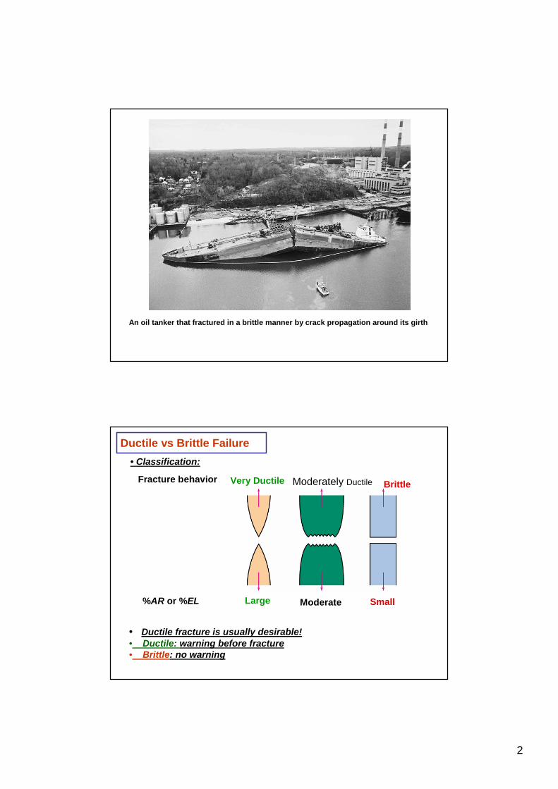
An oil tanker that fractured in a brittle manner by crack propagation around its girth
Ductile vs Brittle Failure
Very Ductile Moderately Ductile BrittleFracture behavior
Large Moderate%AR or %EL Small
• Classification:
• Ductile fracture is usually desirable!• Ductile: warning before fracture• Brittle: no warning

3
• Ductile failure:--one piece--large deformation
Figures from V.J. Colangelo and F.A. Heiser, Analysis of Metallurgical Failures(2nd ed.), Fig. 4.1(a) and (b), p. 66 John Wiley and Sons, Inc., 1987. Used with permission.
Example: Failure of a Pipe
• Brittle failure:--many pieces--small deformation
• Evolution to failure:
• Resultingfracturesurfaces(steel)
50 mm
particlesserve as voidnucleationsites.
50 mm
From V.J. Colangelo and F.A. Heiser, Analysis of Metallurgical Failures (2nd ed.), Fig. 11.28, p. 294, John Wiley and Sons, Inc., 1987. (Orig. source: P. Thornton, J. Mater. Sci., Vol. 6, 1971, pp. 347-56.)
100 mmFracture surface of tire cord wire loaded in tension. Courtesy of F. Roehrig, CC Technologies, Dublin, OH. Used with permission.
Moderately Ductile Failure
necking
s
void nucleation
void growth and linkage
shearing at surface fracture

4
Ductile vs. Brittle Failure
Adapted from Fig. 8.3, Callister 7e.
cup-and-cone fracture brittle fracture
Fractured aluminium alloy I, with a dimpled texture
Fractured aluminium alloy II, with a typical cleavage texture
Fractured tensile test bars
”Cup and cone”

5
Scanning electron micrographs (a) spherical dimples characteristic of ductile fracture, (b) parabolic-shaped dimples characteristic of ductile fracture.
Brittle Failure
Arrows indicate origin of crack

6
Transgranular fracture Intergranular fracture
Brittle Failure
Flaws are Stress Concentrators or stress raisers
Results from crack propagation• Griffith Crack
where rt = radius of curvature of the crack tipso = applied stresssm = stress at crack tip
Kt : stress concentration factor
ot
/
tom K
as=⎟⎟
⎠
⎞⎜⎜⎝
⎛r
s=s
21
2
rt
Principles of fracture mechanics

7
Concentration of Stress at Crack Tip
Adapted from Fig. 8.8(b), Callister 7e.
Engineering Fracture Design
r/h
sharper fillet radius
increasing w/h
0 0.5 1.01.0
1.5
2.0
2.5
Stress Conc. Factor, K tsmaxso
=
• Avoid sharp corners!s
Adapted from Fig. 8.2W(c), Callister 6e.(Fig. 8.2W(c) is from G.H. Neugebauer, Prod. Eng.(NY), Vol. 14, pp. 82-87 1943.)
r , fillet
radius
w
h
o
smax
ot
/
tom K
as=⎟⎟
⎠
⎞⎜⎜⎝
⎛r
s=s
21
2
8
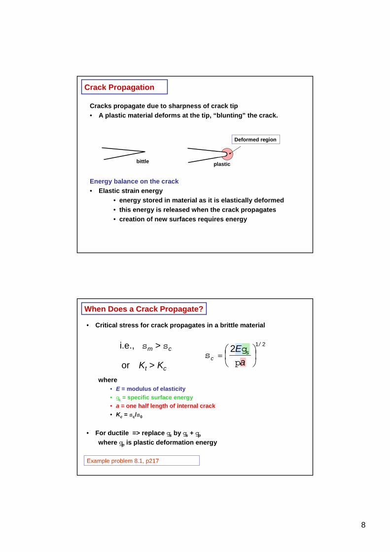
Crack Propagation
Cracks propagate due to sharpness of crack tip • A plastic material deforms at the tip, “blunting” the crack.
Energy balance on the crack• Elastic strain energy
• energy stored in material as it is elastically deformed• this energy is released when the crack propagates• creation of new surfaces requires energy
plasticbittle
Deformed region
When Does a Crack Propagate?
• Critical stress for crack propagates in a brittle material
where• E = modulus of elasticity• gs = specific surface energy• a = one half length of internal crack• Kc = sc/s0
• For ductile => replace gs by gs + gp
where gp is plastic deformation energy
212
/
sc a
E⎟⎠⎞
⎜⎝⎛p
g=s
i.e., sm > sc
or Kt > Kc
Example problem 8.1, p217
9
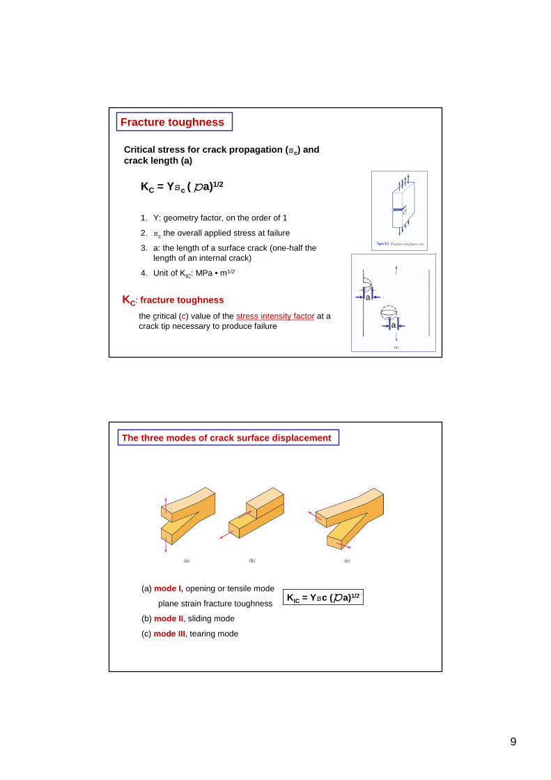
Fracture toughness
KC: fracture toughness
the critical (c) value of the stress intensity factor at a crack tip necessary to produce failure
KC = Ysc ( a)1/2
1. Y: geometry factor, on the order of 1
2. sc the overall applied stress at failure
3. a: the length of a surface crack (one-half the length of an internal crack)
4. Unit of KIC: MPa • m1/2
p
a
a
Critical stress for crack propagation (sc) and crack length (a)
The three modes of crack surface displacement
(a) mode I, opening or tensile mode
plane strain fracture toughness
(b) mode II, sliding mode
(c) mode III, tearing mode
KIC = Ysc ( a)1/2p

10
Room-temperature mechanical properties for selected engineering materials
Fracture ToughnessGraphite/ Ceramics/ Semicond
Metals/ Alloys
Composites/ fibersPolymers
5
KIc
(MP
a·m
0.5)
1
Mg alloysAl alloys
Ti alloys
Steels
Si crystalGlass -soda
Concrete
Si carbide
PC
Glass 6
0.5
0.7
2
4
3
10
20
30
<100>
<111>
Diamond
PVC
PP
Polyester
PS
PET
C-C(|| fibers) 1
0.6
67
40506070
100
Al oxideSi nitride
C/C( fibers) 1
Al/Al oxide(sf) 2
Al oxid/SiC(w) 3
Al oxid/ZrO 2(p)4Si nitr/SiC(w) 5
Glass/SiC(w) 6
Y2O3/ZrO 2(p)4

11
• Crack growth condition:
• Largest, most stressed cracks grow first!
Design Against Crack Growth
K ≥ Kc = aY ps
--Result 1: Max. flaw sizedictates design stress.
max
cdesign
aY
K
p<s
s
amax
no fracture
fracture
--Result 2: Design stressdictates max. flaw size.
2
1⎟⎟⎠
⎞⎜⎜⎝
⎛
sp<
design
cmax Y
Ka
amax
sno fracture
fracture
• Two designs to consider...Design A--largest flaw is 9 mm--failure stress = 112 MPa
Design B--use same material--largest flaw is 4 mm--failure stress = ?
• Key point: Y and Kc are the same in both designs.
Answer: MPa 168)( B =sc• Reducing flaw size pays off!
• Material has Kc = 26 MPa-m0.5
Design Example: Aircraft Wing
• Use...max
cc
aY
K
p=s
sc amax( )
A= sc amax( )
B
9 mm112 MPa 4 mm--Result:

12
Loading Rate• Increased loading rate...
-- increases sy and TS-- decreases %EL
• Why? An increased rategives less time for dislocations to move past obstacles.
s
e
sy
sy
TS
TS
largere
smallere
Charpy test of impact energy
1. A notched specimen – stress concentrating
2. Loading applied rapidly
3. impact energy - the energy necessary to fracture the test specimen
The swinging pendulum
The intial height h
The final height h’
Impact fracture testing
Izod test
Charpy test

13
1040 carbon steel: Fe-0.4C-0.75 Mn
J: joule. 1J = 1N • m
Cu: fcc, ductile
Mg alloy: hcp, relatively brittle
Toughness = , the area under the s - ecurve∫ esd
Fracture
Unit of toughness: N/m2
Or (N/m2) • (mm / mm) = N •m / (mm)3
Toughness: the energy necessary to fracture per unit volume of material
Toughness obtained in a tensile test

14
Temperature dependence of the Charpy V-notch inpact energy and shear fracture for an A283 steel.
Schematic curves for the three general types of impact energy-versus-temperature behavior
More DuctileBrittle

15
Ductile-to-Brittle Transtion Temperature (DBTT)
1. in bcc alloys
2. an abrupt drop in ductility and toughness as the temperature is lowered
Plain-carbon steels with various carbon levels
Fe-Mn-0.05C alloys with various manganese levels
• Pre-WWII: The Titanic • WWII: Liberty ships
• Problem: Used a type of steel with a DBTT ~ Room temp.
Reprinted w/ permission from R.W. Hertzberg, "Deformation and Fracture Mechanics of Engineering Materials", (4th ed.) Fig. 7.1(a), p. 262, John Wiley and Sons, Inc., 1996. (Orig. source: Dr. Robert D. Ballard, The Discovery of the Titanic.)
Reprinted w/ permission from R.W. Hertzberg, "Deformation and Fracture Mechanics of Engineering Materials", (4th ed.) Fig. 7.1(b), p. 262, John Wiley and Sons, Inc., 1996. (Orig. source: Earl R. Parker, "Behavior of Engineering Structures", Nat. Acad. Sci., Nat. Res. Council, John Wiley and Sons, Inc., NY, 1957.)
Design Strategy: Stay Above The DBTT!

16
Fatique
• Fatique = failure under cyclic stress
• failure after N cycles
• load < T.S
Fatique-testing apparatusfor making rotating-bending tests
17
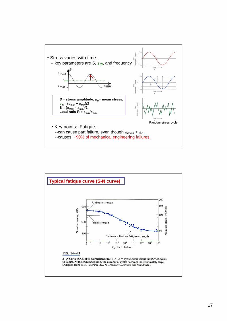
• Stress varies with time.-- key parameters are S, sm, and frequency
smax
smin
s
time
smS
• Key points: Fatigue...--can cause part failure, even though smax < sc.--causes ~ 90% of mechanical engineering failures.
Random stress cycle.
S = stress amplitude, sm= mean stress,sm = (smax + smin)/2S = (smax – smin)/2Load ratio R = smin/smax
Typical fatique curve (S-N curve)
or fatigue strength

18
• Fatigue limit, Sfat:--no fatigue if S < Sfat
Fatigue Design Parameters
Sfat
case for steel (typ.)
N = Cycles to failure103 105 107 109
unsafe
safe
S = stress amplitude
• Sometimes, thefatigue limit is zero! (a
material does not display a fatique limit)
Adapted from Fig. 8.19(b), Callister 7e.
case for Al (typ.)
N = Cycles to failure103 105 107 109
unsafe
safe
S = stress amplitude
Fatique S-N probability of failure curves for a 7075-T6 Al alloy

19
• Crack grows incrementallytyp. 1 to 6
( ) a~ sD
increase in crack length per loading cycle
• Failed rotating shaft--crack grew even though
Kmax < Kc--crack grows faster as
• Ds increases• crack gets longer• loading freq. increases.
crack origin
Fatigue Mechanism
( )mKdNda
D=
Texture of the fatigue fracture surface – clamshell or beachmark texture
Intrusions and extrusions. SEM.

20
Transmission electron fractograph showing fatique striations in aluminum
Each striationis thougth to represent the advance distance of a crack front during a single load cycle, striation width deponds on and incearses with increasing stress range.
Improving Fatigue Life
2. Impose a compressive surface stress (to suppress surface cracks from growing)
--Method 1: shot peening
put surface
into compression
shot--Method 2: carburizing
C-rich gas
3. Remove stress concentrators.bad
bad
better
better
1. Decrease the mean stress level

21
• Engineering materials don't reach theoretical strength.• Flaws produce stress concentrations that cause
premature failure.
• Sharp corners produce large stress concentrationsand premature failure.
• Failure type depends on T and stress:
- for noncyclic s and T < 0.4Tm, failure stress decreases with:- increased maximum flaw size,- decreased T,- increased rate of loading.
- for cyclic s:- cycles to fail decreases as Ds increases.
- for higher T (T > 0.4Tm):- time to fail decreases as s or T increases.
SUMMARY
Homework 8.6 and 8.12, p246