Embed Size (px)
Citation preview
4110 STAINLESS STEEL
Capacities (lbf):500, 1K, 2K, 5KFeatures:• Stainless steel construction• Compact size• Welded diaphragm• Tension and compression
Capacities (lbf):100K, 135K, 250K, 500KFeatures:• Universal tension and
compression• 4 column cell• Accommodates high side and off-center loads
5200 UNIVERSAL HIGH CAPACITY
LOW CAPACITY FATIGUE RATED (FR5)
Capacities (lbf):50, 100, 300Features:• Metric capacities available• Fatigue rated• Small scale• Sealed• Static error band .05%
(SWS) SHEAR WEB STAINLESS STEEL
Capacities (lbf):5K, 10K, 25K, 50K, 100KFeatures:• Stainless steel construction• Welded diaphragm• Optional hermetically sealed connector
Shown with optional integral cable
(FRS) FATIGUE RATED STAINLESS STEEL
Capacities (lbf):2.5K, 5K, 12.5K, 25KFeatures:• Stainless steel construction• Welded diaphragm• Optional hermetically sealed connector
Shown with optional connector & connector box
(SWP) SHEAR WEB HIGH CAPACITY
Capacities (lbf):200K, 270K, 300K, 400K, 500K, 600K, 750K, 1000K Capacities (kN):1000, 1200, 1400, 1800, 2200, 2700, 3300, 4500Features:• High accuracy version of Shear
Web Metric series• Low creep
CALIBRATION STANDARD (CS) FORCE TRANSDUCER
Capacities (lbf):300, 500, 1K, 2K, 5K, 10K, 25K, 50K, 60K, 100KCapacities (kN):1.5, 2.5, 5, 10, 25, 50, 100, 250, 300, 500Features:• Designed for Metrology Lab use• Meets ASTM E74 requirements
Class A to 2% of range Class AA
5000 HIGH CAPACITY UNIVERSAL COLUMN
Capacities (lbf):100K, 250K, 300K, 500K, 600K, 750K, 1000KFeatures:• Universal tension and
compression• .2% accuracy • Bayonet connector
(FR) SHEAR WEB FATIGUE RATED
Capacities (lbf):150, 250, 500, 1K, 2.5K, 5K, 12.5K, 25K, 50KCapacities (kN):750, 1.25, 2.5, 5, 12.5, 25, 50, 125, 150, 250Features:• Guaranteed for 100 million fully
reversed cycles• Low deflection
(SW) SHEAR WEB HIGH CAPACITY
Capacities (lbf):200K, 270K, 300K, 400K, 500K, 600K, 750K, 1000KCapacities (kN):1000, 1200, 1335, 1779, 2200, 2700, 3300, 4500Features:• First choice for structural and
materials testing• Available in compression only
(FR) SHEAR WEB METRIC HIGH CAPACITY
Capacities (lbf):100K, 135K, 150K, 200K, 250K, 300K, 375K, 500KCapacities (kN):500, 600, 700, 900, 1100, 1350, 1650, 2250Features:• Guaranteed for 100 million fully
reversed cycles• Low deflection
(CS) CALIBRATION STANDARD HIGH CAPACITY
Capacities (lbf):200K, 270K, 300K, 400K, 500K,600KCapacities (kN):1000, 1200, 2200, 2700Features:• Designed for Metrology Lab use• Meets ASTM E74 requirements
Class A to 4% of rangeClass AA to 20% of range (most models)
(SW) SHEAR WEB FORCE TRANSDUCER
Capacities (lbf):300, 500, 1K, 2K, 5K, 10K, 25K,50K, 60K, 100KCapacities (kN):1.5 , 2.5, 5, 10, 25, 50, 100, 250, 300, 500Features:• First choice for structural and
materials testing• Available in compression only
(SWP) SHEAR WEB PRECISION
Capacities (lbf):300, 500, 1K, 2K, 5K, 10K, 25K,50K, 60K, 100KCapacities (kN):1.5 , 2.5, 5, 10, 25, 50, 100, 250, 300, 500Features:• High accuracy version of Shear
Web series• Low creep
5100 HIGH CAPACITY COMPRESSION COLUMN
Capacities (lbf):100K, 250K, 300K, 500K, 600K, 750K, 1000KFeatures:• Compact design• .2% accuracy• Special capacities to
2 million lbf.
4120 STAINLESS STEEL
Capacities (lbf):10K, 20KFeatures:• Stainless steel construction• Welded diaphragm• Tension and compression• Optional hermetically sealed connector
MINIATURE REACTION TORQUE (RT)
Capacities (in-lb):25, 50, 100, 200, 250, 500Features:• Compact size• Accuracy--.1% of Rated Output• Capacities from 25 to 500 in-lb
PREMIUM “S” TYPE (SSC) SERIES
Capacities (lbf):50, 100, 250, 500, 1K, 2K, 3K, 5KFeatures:• Premium version of the
standard “S” cell• In-line loading• Sealed for environmental protection
2202 ROD END LOAD CELL
Capacities (lbf):5K, 10K, 15K, 25KFeatures:• Designed to attach directly on Hydrau-lic Cylinders• High Capacity vs. Size• Low Deflection• Stable and Accurate• 5pt Tension & Compression Calibration
(SCT) PRECISION OVERLOAD PROTECTED
Capacities (N):10, 20, 50, 100, 250, 500Features:• Overload protected to 1000% of FS
in both tension and compression• High accuracy--.02% of Rated
Output• Integral cable• U.S. lbf. capacities available
Capacities (lbf):5, 10, 25, 50, 100, 200, 300, 500, 1KFeatures:• Compact size• Tension and compression• Accuracy--.05%-.10% of Rated
Output.• Integral cable• Metric capacities available
(SLH) LOW HEIGHT S-TYPE
LW SERIES LOAD WASHER
Capacities (lbf):2K, 3K, 5K, 7.5K, 10KFeatures:• Compact size (.5 to 1.12” Dia.)• Hollow cylinder• Integral cable• Special sizes & capacities
available• Optional stainless steel
Capacities (lbf):10K, 25KFeatures:• Compact size• Accuracy--.05%-.07% of Rated
Output• Optional full encapsulation for harsh
environments
2121 COMPACT STAINLESS STEEL COMPRESSION
AXIAL FORCE AND TORQUE (SWT)
Capacities (lbf/in-lb):300/150, 500/250, 1K/500, 2K/1K, 5K/2K, 10K/5KFeatures:• Measure both force and torque• High accuracy both bridges• Low crosstalk
(SW-XYZ) AXIAL FORCE AND MOMENT
Capacities (lbf/in-lb):1K/400, 2K/800, 5K/1K, 10K/2K, 25K/10K, 50K/20K, 100K/50KFeatures:• Measure z-axis force, x- and y-axis
moment• High accuracy force measurement
9150 HIGH PRECISION INDICATOR
Features:• 24-bit resolution• 10-point linearization• Linearity of 0.005% of full scale• Sensitivity of ±4.5 mV/V• 2 channel transducer input• Software selectable filters
7230 PORTABLE STRAIN DISPLAY INDICATOR
Features:• Portable hand held instrument• Powered by 2 AA internal
batteries • Environmentally sealed to IP65/
NEMA 4• Optional RS-232 computer interface
Features:• 20-bit resolution• 5-point linearization • Legal for trade capability• Lb and Kg measurement units• RS-232 computer interface
7120 SEALED GENERALPURPOSE INDICATOR
2206ROD END LOAD CELL
Features: Designed to attach directly on Hydraulic Cylinders• High Capacity vs. Size• Low Deflection• Stable and Accurate• 5pt Tension & Compression Calibration
TS-10-2 TRANSDUCER SIMULATOR
Features:• High accuracy calibration
standard transducer simulator• <.015% error• Long-term stability• Low temp. Coefficient of output• 20 output steps
SGA/A & SGA/D STRAIN GAGE AMPLIFIER
Features:• 10V excitation for up to 4 x 350R
bridges• Adjustable sensitivity 0.1
to 30 mV/V• User selectable analog output• Simultaneous voltage and
current output
ROD END COLUMN (2029/2030) SERIES
Capacities (lbf):2029: 500, 1K, 5K 2030: 2.5K, 5K, 7.5KFeatures:• Sealed for environmental protection• Water immersion to 300 ft.• Integral cable • Male /Female threads available
Shown with Optional Female Thread.
© 2011 Tovey Engineering, Inc. © 2011 Tovey Engineering, Inc.
Page 4 Page 5
TABLE OF CONTENTS
TABLE OF CONTENTS
© 2011 Tovey Engineering, Inc. © 2011 Tovey Engineering, Inc.
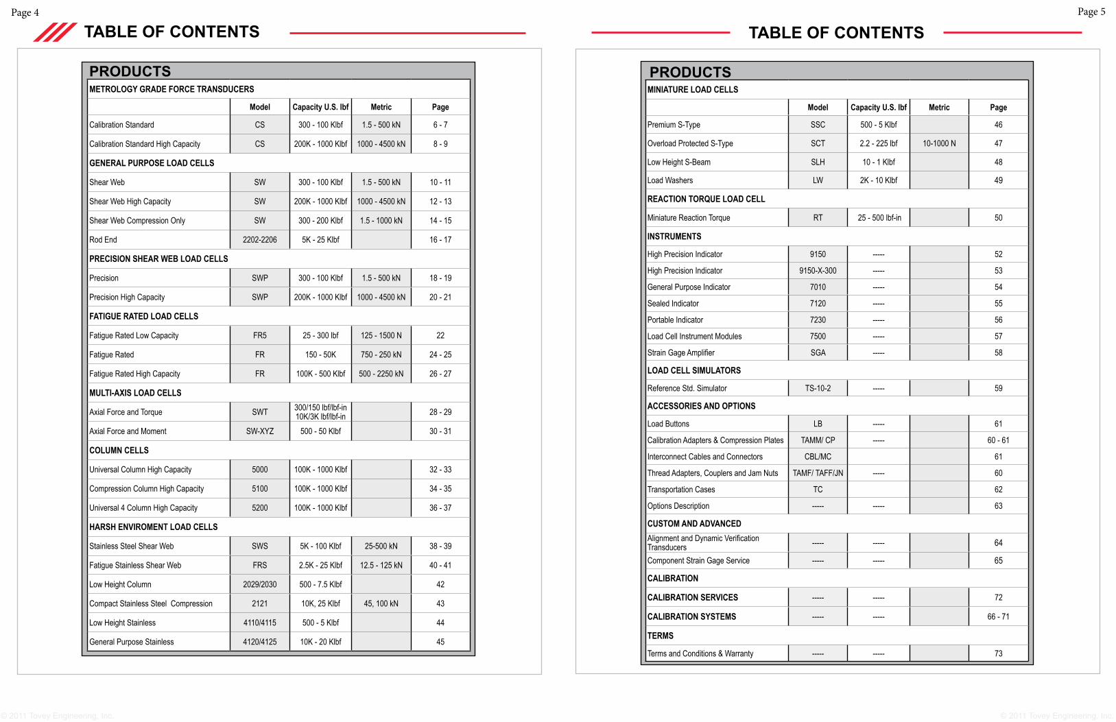
PRODUCTSMINIATURE LOAD CELLS
Model Capacity U.S. lbf Metric Page
Premium S-Type SSC 500 - 5 Klbf 46
Overload Protected S-Type SCT 2.2 - 225 lbf 10-1000 N 47
Low Height S-Beam SLH 10 - 1 Klbf 48
Load Washers LW 2K - 10 Klbf 49
REACTION TORQUE LOAD CELL
Miniature Reaction Torque RT 25 - 500 lbf-in 50
INSTRUMENTS
High Precision Indicator 9150 ----- 52
High Precision Indicator 9150-X-300 ----- 53
General Purpose Indicator 7010 ----- 54
Sealed Indicator 7120 ----- 55
Portable Indicator 7230 ----- 56
Load Cell Instrument Modules 7500 ----- 57
Strain Gage Amplifier SGA ----- 58
LOAD CELL SIMULATORS
Reference Std. Simulator TS-10-2 ----- 59
ACCESSORIES AND OPTIONS
Load Buttons LB ----- 61
Calibration Adapters & Compression Plates TAMM/ CP ----- 60 - 61
Interconnect Cables and Connectors CBL/MC 61
Thread Adapters, Couplers and Jam Nuts TAMF/ TAFF/JN ----- 60
Transportation Cases TC 62
Options Description ----- ----- 63
CUSTOM AND ADVANCED Alignment and Dynamic Verification Transducers ----- ----- 64
Component Strain Gage Service ----- ----- 65
CALIBRATION
CALIBRATION SERVICES ----- ----- 72
CALIBRATION SYSTEMS ----- ----- 66 - 71
TERMS
Terms and Conditions & Warranty ----- ----- 73
PRODUCTSMETROLOGY GRADE FORCE TRANSDUCERS
Model Capacity U.S. lbf Metric Page
Calibration Standard CS 300 - 100 Klbf 1.5 - 500 kN 6 - 7
Calibration Standard High Capacity CS 200K - 1000 Klbf 1000 - 4500 kN 8 - 9
GENERAL PURPOSE LOAD CELLS
Shear Web SW 300 - 100 Klbf 1.5 - 500 kN 10 - 11
Shear Web High Capacity SW 200K - 1000 Klbf 1000 - 4500 kN 12 - 13
Shear Web Compression Only SW 300 - 200 Klbf 1.5 - 1000 kN 14 - 15
Rod End 2202-2206 5K - 25 Klbf 16 - 17
PRECISION SHEAR WEB LOAD CELLS
Precision SWP 300 - 100 Klbf 1.5 - 500 kN 18 - 19
Precision High Capacity SWP 200K - 1000 Klbf 1000 - 4500 kN 20 - 21
FATIGUE RATED LOAD CELLS
Fatigue Rated Low Capacity FR5 25 - 300 lbf 125 - 1500 N 22
Fatigue Rated FR 150 - 50K 750 - 250 kN 24 - 25
Fatigue Rated High Capacity FR 100K - 500 Klbf 500 - 2250 kN 26 - 27
MULTI-AXIS LOAD CELLS
Axial Force and Torque SWT 300/150 lbf/lbf-in10K/3K lbf/lbf-in 28 - 29
Axial Force and Moment SW-XYZ 500 - 50 Klbf 30 - 31
COLUMN CELLS
Universal Column High Capacity 5000 100K - 1000 Klbf 32 - 33
Compression Column High Capacity 5100 100K - 1000 Klbf 34 - 35
Universal 4 Column High Capacity 5200 100K - 1000 Klbf 36 - 37
HARSH ENVIROMENT LOAD CELLS
Stainless Steel Shear Web SWS 5K - 100 Klbf 25-500 kN 38 - 39
Fatigue Stainless Shear Web FRS 2.5K - 25 Klbf 12.5 - 125 kN 40 - 41
Low Height Column 2029/2030 500 - 7.5 Klbf 42
Compact Stainless Steel Compression 2121 10K, 25 Klbf 45, 100 kN 43
Low Height Stainless 4110/4115 500 - 5 Klbf 44
General Purpose Stainless 4120/4125 10K - 20 Klbf 45
Page 7Page 6
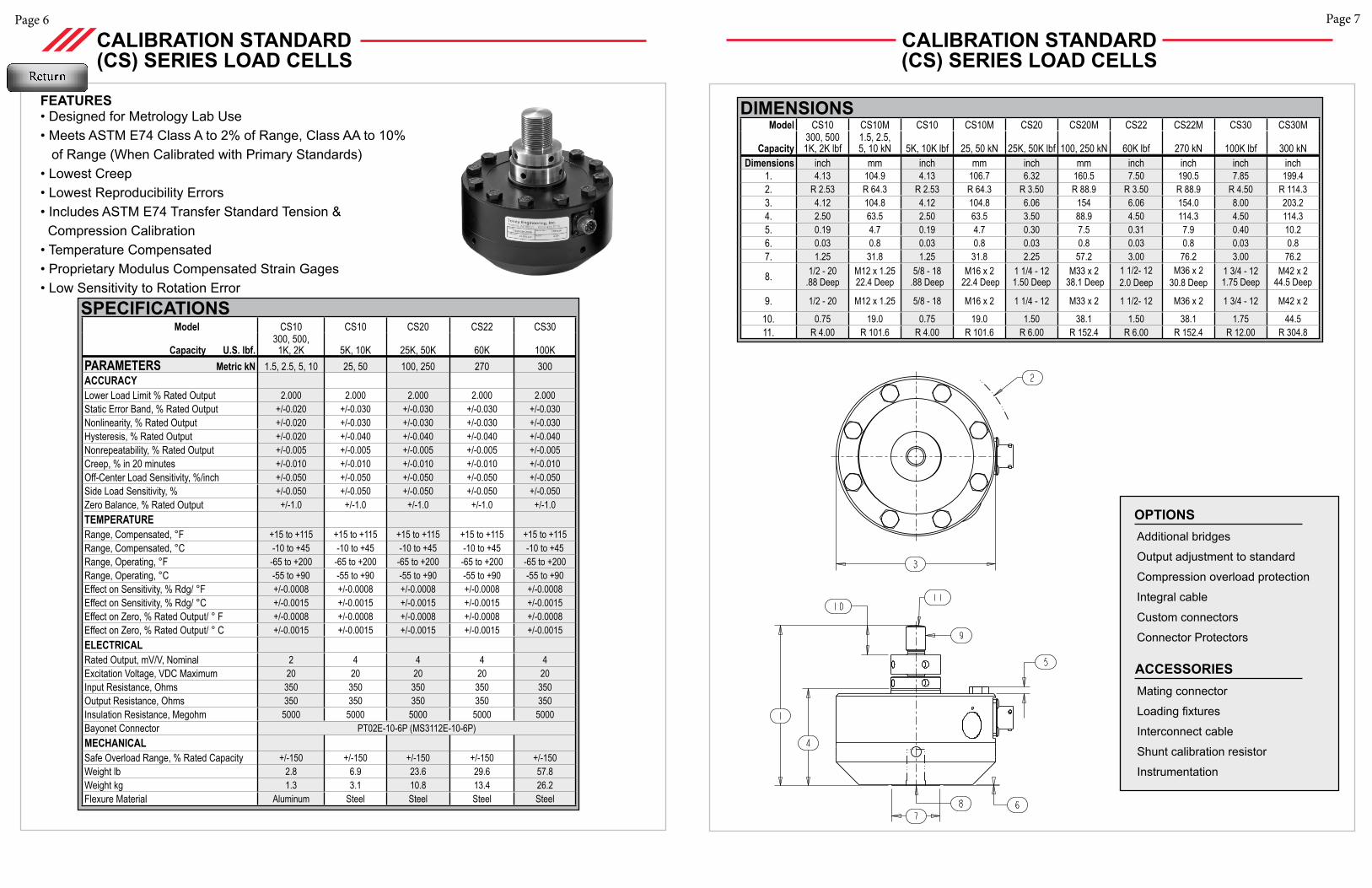
Additional bridges
Output adjustment to standard
Compression overload protection
Integral cable
Custom connectors
Connector Protectors
OPTIONS
Mating connector
Loading fixtures
Interconnect cable
Shunt calibration resistor
Instrumentation
ACCESSORIES
SPECIFICATIONS Model CS10 CS10 CS20 CS22 CS30
Capacity U.S. lbf.300, 500,
1K, 2K 5K, 10K 25K, 50K 60K 100KPARAMETERS Metric kN 1.5, 2.5, 5, 10 25, 50 100, 250 270 300ACCURACY Lower Load Limit % Rated Output 2.000 2.000 2.000 2.000 2.000Static Error Band, % Rated Output +/-0.020 +/-0.030 +/-0.030 +/-0.030 +/-0.030Nonlinearity, % Rated Output +/-0.020 +/-0.030 +/-0.030 +/-0.030 +/-0.030Hysteresis, % Rated Output +/-0.020 +/-0.040 +/-0.040 +/-0.040 +/-0.040Nonrepeatability, % Rated Output +/-0.005 +/-0.005 +/-0.005 +/-0.005 +/-0.005Creep, % in 20 minutes +/-0.010 +/-0.010 +/-0.010 +/-0.010 +/-0.010Off-Center Load Sensitivity, %/inch +/-0.050 +/-0.050 +/-0.050 +/-0.050 +/-0.050Side Load Sensitivity, % +/-0.050 +/-0.050 +/-0.050 +/-0.050 +/-0.050Zero Balance, % Rated Output +/-1.0 +/-1.0 +/-1.0 +/-1.0 +/-1.0TEMPERATURERange, Compensated, °F +15 to +115 +15 to +115 +15 to +115 +15 to +115 +15 to +115Range, Compensated, °C -10 to +45 -10 to +45 -10 to +45 -10 to +45 -10 to +45Range, Operating, °F -65 to +200 -65 to +200 -65 to +200 -65 to +200 -65 to +200Range, Operating, °C -55 to +90 -55 to +90 -55 to +90 -55 to +90 -55 to +90Effect on Sensitivity, % Rdg/ °F +/-0.0008 +/-0.0008 +/-0.0008 +/-0.0008 +/-0.0008Effect on Sensitivity, % Rdg/ °C +/-0.0015 +/-0.0015 +/-0.0015 +/-0.0015 +/-0.0015Effect on Zero, % Rated Output/ ° F +/-0.0008 +/-0.0008 +/-0.0008 +/-0.0008 +/-0.0008Effect on Zero, % Rated Output/ ° C +/-0.0015 +/-0.0015 +/-0.0015 +/-0.0015 +/-0.0015ELECTRICALRated Output, mV/V, Nominal 2 4 4 4 4Excitation Voltage, VDC Maximum 20 20 20 20 20Input Resistance, Ohms 350 350 350 350 350Output Resistance, Ohms 350 350 350 350 350Insulation Resistance, Megohm 5000 5000 5000 5000 5000Bayonet Connector PT02E-10-6P (MS3112E-10-6P)MECHANICALSafe Overload Range, % Rated Capacity +/-150 +/-150 +/-150 +/-150 +/-150Weight lb 2.8 6.9 23.6 29.6 57.8Weight kg 1.3 3.1 10.8 13.4 26.2 Flexure Material Aluminum Steel Steel Steel Steel
FEATURES• Designed for Metrology Lab Use• Meets ASTM E74 Class A to 2% of Range, Class AA to 10% of Range (When Calibrated with Primary Standards)• Lowest Creep• Lowest Reproducibility Errors• Includes ASTM E74 Transfer Standard Tension & Compression Calibration• Temperature Compensated• Proprietary Modulus Compensated Strain Gages• Low Sensitivity to Rotation Error
CALIBRATION STANDARD (CS) SERIES LOAD CELLS
CALIBRATION STANDARD (CS) SERIES LOAD CELLS
Model CS10 CS10M CS10 CS10M CS20 CS20M CS22 CS22M CS30 CS30M
Capacity300, 5001K, 2K lbf
1.5, 2.5, 5, 10 kN 5K, 10K lbf 25, 50 kN 25K, 50K lbf 100, 250 kN 60K lbf 270 kN 100K lbf 300 kN
Dimensions inch mm inch mm inch mm inch inch inch inch1. 4.13 104.9 4.13 106.7 6.32 160.5 7.50 190.5 7.85 199.42. R 2.53 R 64.3 R 2.53 R 64.3 R 3.50 R 88.9 R 3.50 R 88.9 R 4.50 R 114.33. 4.12 104.8 4.12 104.8 6.06 154 6.06 154.0 8.00 203.24. 2.50 63.5 2.50 63.5 3.50 88.9 4.50 114.3 4.50 114.35. 0.19 4.7 0.19 4.7 0.30 7.5 0.31 7.9 0.40 10.26. 0.03 0.8 0.03 0.8 0.03 0.8 0.03 0.8 0.03 0.87. 1.25 31.8 1.25 31.8 2.25 57.2 3.00 76.2 3.00 76.2
8. 1/2 - 20.88 Deep
M12 x 1.25 22.4 Deep
5/8 - 18.88 Deep
M16 x 2 22.4 Deep
1 1/4 - 12 1.50 Deep
M33 x 2 38.1 Deep
1 1/2- 122.0 Deep
M36 x 230.8 Deep
1 3/4 - 12 1.75 Deep
M42 x 2 44.5 Deep
9. 1/2 - 20 M12 x 1.25 5/8 - 18 M16 x 2 1 1/4 - 12 M33 x 2 1 1/2- 12 M36 x 2 1 3/4 - 12 M42 x 2
10. 0.75 19.0 0.75 19.0 1.50 38.1 1.50 38.1 1.75 44.511. R 4.00 R 101.6 R 4.00 R 101.6 R 6.00 R 152.4 R 6.00 R 152.4 R 12.00 R 304.8
DIMENSIONS
Page 9Page 8
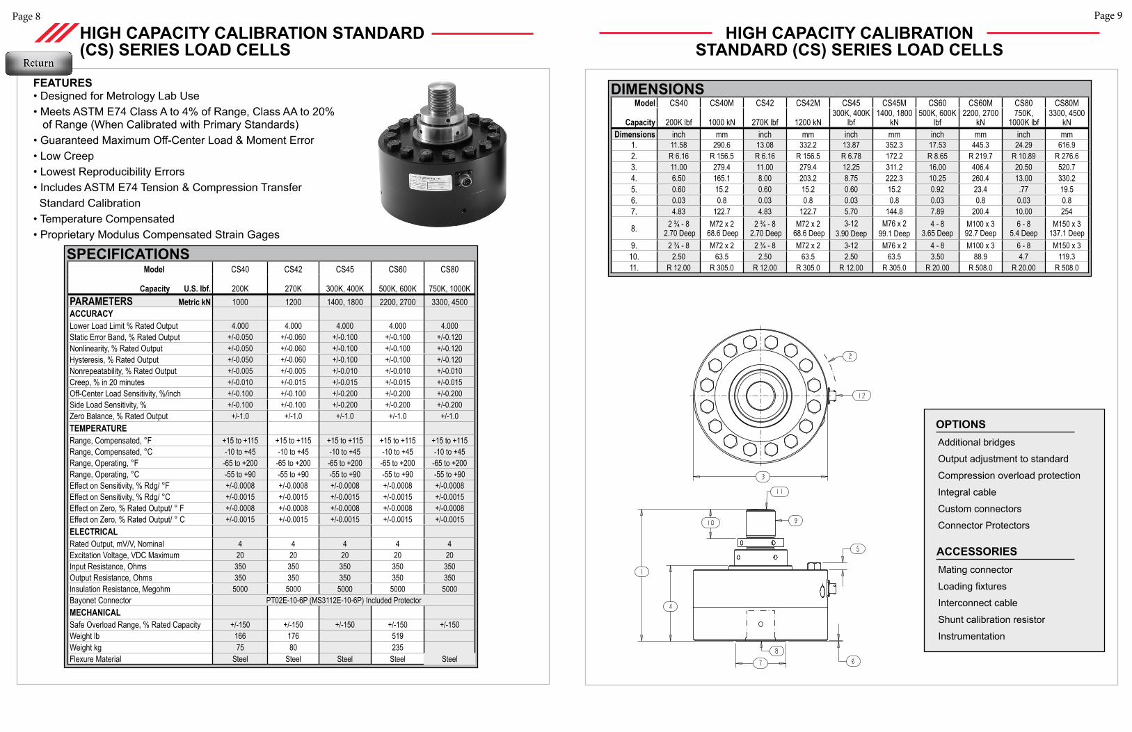
Additional bridges
Output adjustment to standard
Compression overload protection
Integral cable
Custom connectors
Connector Protectors
OPTIONS
Mating connector
Loading fixtures
Interconnect cable
Shunt calibration resistor
Instrumentation
ACCESSORIES
SPECIFICATIONS Model CS40 CS42 CS45 CS60 CS80
Capacity U.S. lbf. 200K 270K 300K, 400K 500K, 600K 750K, 1000KPARAMETERS Metric kN 1000 1200 1400, 1800 2200, 2700 3300, 4500ACCURACY Lower Load Limit % Rated Output 4.000 4.000 4.000 4.000 4.000Static Error Band, % Rated Output +/-0.050 +/-0.060 +/-0.100 +/-0.100 +/-0.120Nonlinearity, % Rated Output +/-0.050 +/-0.060 +/-0.100 +/-0.100 +/-0.120Hysteresis, % Rated Output +/-0.050 +/-0.060 +/-0.100 +/-0.100 +/-0.120Nonrepeatability, % Rated Output +/-0.005 +/-0.005 +/-0.010 +/-0.010 +/-0.010Creep, % in 20 minutes +/-0.010 +/-0.015 +/-0.015 +/-0.015 +/-0.015Off-Center Load Sensitivity, %/inch +/-0.100 +/-0.100 +/-0.200 +/-0.200 +/-0.200Side Load Sensitivity, % +/-0.100 +/-0.100 +/-0.200 +/-0.200 +/-0.200Zero Balance, % Rated Output +/-1.0 +/-1.0 +/-1.0 +/-1.0 +/-1.0TEMPERATURERange, Compensated, °F +15 to +115 +15 to +115 +15 to +115 +15 to +115 +15 to +115Range, Compensated, °C -10 to +45 -10 to +45 -10 to +45 -10 to +45 -10 to +45Range, Operating, °F -65 to +200 -65 to +200 -65 to +200 -65 to +200 -65 to +200Range, Operating, °C -55 to +90 -55 to +90 -55 to +90 -55 to +90 -55 to +90Effect on Sensitivity, % Rdg/ °F +/-0.0008 +/-0.0008 +/-0.0008 +/-0.0008 +/-0.0008Effect on Sensitivity, % Rdg/ °C +/-0.0015 +/-0.0015 +/-0.0015 +/-0.0015 +/-0.0015Effect on Zero, % Rated Output/ ° F +/-0.0008 +/-0.0008 +/-0.0008 +/-0.0008 +/-0.0008Effect on Zero, % Rated Output/ ° C +/-0.0015 +/-0.0015 +/-0.0015 +/-0.0015 +/-0.0015ELECTRICALRated Output, mV/V, Nominal 4 4 4 4 4Excitation Voltage, VDC Maximum 20 20 20 20 20Input Resistance, Ohms 350 350 350 350 350Output Resistance, Ohms 350 350 350 350 350Insulation Resistance, Megohm 5000 5000 5000 5000 5000Bayonet Connector PT02E-10-6P (MS3112E-10-6P) Included ProtectorMECHANICALSafe Overload Range, % Rated Capacity +/-150 +/-150 +/-150 +/-150 +/-150Weight lb 166 176 519Weight kg 75 80 235 Flexure Material Steel Steel Steel Steel Steel
FEATURES• Designed for Metrology Lab Use• Meets ASTM E74 Class A to 4% of Range, Class AA to 20% of Range (When Calibrated with Primary Standards)• Guaranteed Maximum Off-Center Load & Moment Error• Low Creep• Lowest Reproducibility Errors• Includes ASTM E74 Tension & Compression Transfer Standard Calibration• Temperature Compensated• Proprietary Modulus Compensated Strain Gages
HIGH CAPACITY CALIBRATION STANDARD (CS) SERIES LOAD CELLS
HIGH CAPACITY CALIBRATION STANDARD (CS) SERIES LOAD CELLS
Model CS40 CS40M CS42 CS42M CS45 CS45M CS60 CS60M CS80 CS80M
Capacity 200K lbf 1000 kN 270K lbf 1200 kN300K, 400K
lbf1400, 1800
kN500K, 600K
lbf2200, 2700
kN750K,
1000K lbf3300, 4500
kNDimensions inch mm inch mm inch mm inch mm inch mm
1. 11.58 290.6 13.08 332.2 13.87 352.3 17.53 445.3 24.29 616.92. R 6.16 R 156.5 R 6.16 R 156.5 R 6.78 172.2 R 8.65 R 219.7 R 10.89 R 276.63. 11.00 279.4 11.00 279.4 12.25 311.2 16.00 406.4 20.50 520.74. 6.50 165.1 8.00 203.2 8.75 222.3 10.25 260.4 13.00 330.25. 0.60 15.2 0.60 15.2 0.60 15.2 0.92 23.4 .77 19.56. 0.03 0.8 0.03 0.8 0.03 0.8 0.03 0.8 0.03 0.87. 4.83 122.7 4.83 122.7 5.70 144.8 7.89 200.4 10.00 254
8. 2 ¾ - 8 2.70 Deep
M72 x 2 68.6 Deep
2 ¾ - 8 2.70 Deep
M72 x 2 68.6 Deep
3-123.90 Deep
M76 x 299.1 Deep
4 - 83.65 Deep
M100 x 3 92.7 Deep
6 - 85.4 Deep
M150 x 3 137.1 Deep
9. 2 ¾ - 8 M72 x 2 2 ¾ - 8 M72 x 2 3-12 M76 x 2 4 - 8 M100 x 3 6 - 8 M150 x 310. 2.50 63.5 2.50 63.5 2.50 63.5 3.50 88.9 4.7 119.311. R 12.00 R 305.0 R 12.00 R 305.0 R 12.00 R 305.0 R 20.00 R 508.0 R 20.00 R 508.0
DIMENSIONS

Page 11Page 10
Additional bridgesOutput adjustment to standardCompression overload protectionIntegral cableCustom connectors
Connector Protectors
Base
OPTIONS
Mating connectorLoading fixturesInterconnect cableShunt calibration resistorInstrumentation
ACCESSORIES
SPECIFICATIONS
SHEAR WEB (SW) SERIES LOAD CELLS
Model SW10 SW10 SW20 SW22 SW30
Capacity U.S. lbf.300, 500, 1K, 2K 5K, 10K 25K, 50K 60K 100K
PARAMETERS Metric kN 1.5, 2.5, 5, 10 25, 50 100, 250 270 300, 500ACCURACY Static Error Band, % Rated Output +/-0.040 +/-0.050 +/-0.050 +/-0.050 +/-0.050Nonlinearity, % Rated Output +/-0.040 +/-0.050 +/-0.050 +/-0.050 +/-0.050Hysteresis, % Rated Output +/-0.030 +/-0.050 +/-0.050 +/-0.050 +/-0.050Nonrepeatability, % Rated Output +/-0.010 +/-0.010 +/-0.010 +/-0.010 +/-0.010Creep, % in 20 minutes +/-0.025 +/-0.025 +/-0.025 +/-0.025 +/-0.025Off-Center Load Sensitivity, %/inch +/-0.250 +/-0.250 +/-0.250 +/-0.250 +/-0.250Side Load Sensitivity, % +/-0.250 +/-0.250 +/-0.250 +/-0.250 +/-0.250Zero Balance, % Rated Output +/-1.0 +/-1.0 +/-1.0 +/-1.0 +/-1.0TEMPERATURERange, Compensated, °F +15 to +115 +15 to +115 +15 to +115 +15 to +115 +15 to +115Range, Compensated, °C -10 to +45 -10 to +45 -10 to +45 -10 to +45 -10 to +45Range, Operating, °F -65 to +200 -65 to +200 -65 to +200 -65 to +200 -65 to +200Range, Operating, °C -55 to +90 -55 to +90 -55 to +90 -55 to +90 -55 to +90Effect on Sensitivity, % Rdg/ °F +/-0.0008 +/-0.0008 +/-0.0008 +/-0.0008 +/-0.0008Effect on Sensitivity, % Rdg/ °C +/-0.0015 +/-0.0015 +/-0.0015 +/-0.0015 +/-0.0015Effect on Zero, % Rated Output/ °F +/-0.0008 +/-0.0008 +/-0.0008 +/-0.0008 +/-0.0008Effect on Zero, % Rated Output/ °C +/-0.0015 +/-0.0015 +/-0.0015 +/-0.0015 +/-0.0015ELECTRICALRated Output, mV/V, Nominal 2 4 4 4 4Excitation Voltage, VDC Maximum 20 20 20 20 20Input Resistance, Ohms 350 350 350 350 350Output Resistance, Ohms 350 350 350 350 350Insulation Resistance, Megohm 5000 5000 5000 5000 5000Bayonet Connector PT02E-10-6P (MS3112E-10-6P)MECHANICALSafe Overload Range, % Rated Capacity +/-150 +/-150 +/-150 +/-150 +/-150Weight lb 1.0 2.9 9.1 13.5 23.5Weight kg 0.5 1.3 4.1 6.1 10.7 Weight w/base lb 2.5 6.5 21.5 27.5 52.5Weight w/base kg 1.1 3.0 9.8 12.5 23.8 Flexure Material Aluminum Steel Steel Steel Steel
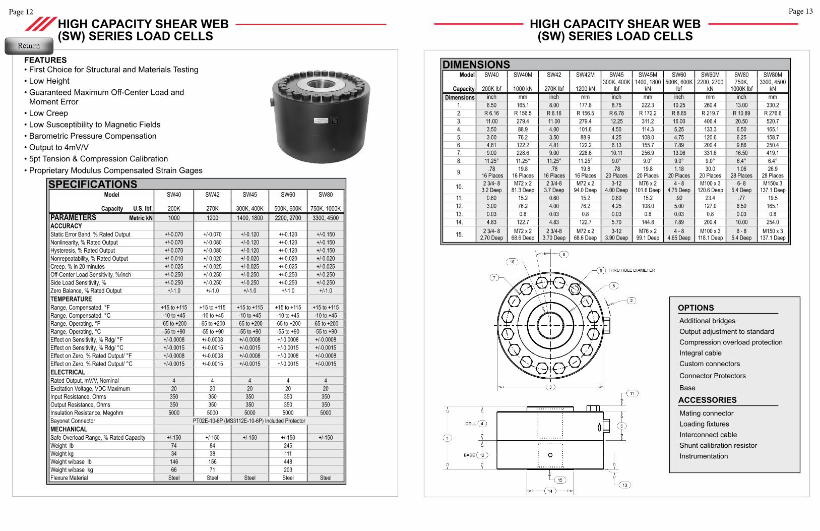
FEATURES• First Choice for Structural and Materials Testing• Low Height• Guaranteed Maximum Off-Center Load & Moment Error• Low Creep• Low Susceptibility to Magnetic Fields• Barometric Pressure Compensation• Output to 4mV/V• 5pt Tension & Compression Calibration• Proprietary Modulus Compensated Strain Gages
SHEAR WEB (SW) SERIES LOAD CELLS
DIMENSIONSModel SW10 SW10M SW10 SW10M SW20 SW20M SW22 SW22M SW30 SW30M
Capacity300, 500, 1K, 2K lbf
1.5, 2.5, 5, 10 kN
5K, 10K lbf 25, 50 kN
25K,50K lbf
100, 250 kN 60K lbf 270 kN 100K lbf 300, 500 kN
Dimensions inch mm inch mm inch mm inch mm inch mm1. 2.51 63.5 2.51 63.5 3.51 88.9 4.50 114.3 4.50 114.32. R 2.53 R 64.3 R 2.53 R 64.3 R 3.50 R 88.9 R 3.50 R 88.9 R 4.50 R 114.33. 4.12 104.8 4.12 104.8 6.06 154.0 6.06 154.0 8.00 203.24. 1.38 34.9 1.38 34.9 1.75 44.5 2.25 57.2 2.50 63.55. 1.25 31.8 1.25 31.8 1.63 41.3 2.13 54.1 2.25 57.2
6. 1.29 32.8 1.29 32.8 2.34 25K2.58 50K
59.4 100kN 65.6 250kN 2.58 65.6 3.76 95.6
7. 3.50 88.9 3.50 88.9 5.13 130.3 5.13 130.3 6.50 165.18. 22.5° 22.5° 22.5° 22.5° 15° 15° 15° 15° 11.25° 11.25°
9. .288 Places
7.18 Places
.288 Places
7.18 Places
.4112 Places
10.312 Places
.4712 Places
11.912 Places
.5316 Places
13.516 Places
10. 1/2-201.12 Deep
M12 x 1.2528.5 Deep
5/8 - 181.12 Deep
M16 x 228.5 Deep.
1 1/4 - 121.50 Deep
M33x 238.1 Deep
1 1/2 - 12 2.0 Deep
M36x 250.8 Deep
1 3/4-12 2.20 Deep
M42 x 255.9 Deep
11. 0.18 4.7 0.18 4.7 0.29 7.5 0.31 7.9 .40 10.212. 1.13 28.6 1.13 28.6 1.75 44.5 2.25 57.2 2.00 50.813. 0.03 0.8 0.03 0.8 0.03 0.8 0.03 0.8 0.03 0.814. 1.25 31.8 1.25 31.8 2.25 57.2 3.00 76.2 3.00 76.2
15. 1/2-20.88 Deep
M12 x 1.2522.4 Deep
5/8 - 18 .88 Deep
M16 x 222.4 Deep
1 1/4 - 12 1.50 Deep
M33 x 238.1 Deep
1 1/2 - 12 2.00 Deep
M36 x 250.8 Deep
1 3/4-121.75 Deep
M42 x 2 44.5 Deep
Page 13Page 12
Additional bridgesOutput adjustment to standardCompression overload protectionIntegral cableCustom connectors
Connector Protectors
Base
OPTIONS
Mating connectorLoading fixturesInterconnect cableShunt calibration resistorInstrumentation
ACCESSORIES
SPECIFICATIONS
FEATURES• First Choice for Structural and Materials Testing• Low Height• Guaranteed Maximum Off-Center Load and
Moment Error• Low Creep• Low Susceptibility to Magnetic Fields• Barometric Pressure Compensation• Output to 4mV/V• 5pt Tension & Compression Calibration• Proprietary Modulus Compensated Strain Gages
Model SW40 SW42 SW45 SW60 SW80
Capacity U.S. lbf. 200K 270K 300K, 400K 500K, 600K 750K, 1000KPARAMETERS Metric kN 1000 1200 1400, 1800 2200, 2700 3300, 4500ACCURACY Static Error Band, % Rated Output +/-0.070 +/-0.070 +/-0.120 +/-0.120 +/-0.150Nonlinearity, % Rated Output +/-0.070 +/-0.080 +/-0.120 +/-0.120 +/-0.150Hysteresis, % Rated Output +/-0.070 +/-0.080 +/-0.120 +/-0.120 +/-0.150Nonrepeatability, % Rated Output +/-0.010 +/-0.020 +/-0.020 +/-0.020 +/-0.020Creep, % in 20 minutes +/-0.025 +/-0.025 +/-0.025 +/-0.025 +/-0.025Off-Center Load Sensitivity, %/inch +/-0.250 +/-0.250 +/-0.250 +/-0.250 +/-0.250Side Load Sensitivity, % +/-0.250 +/-0.250 +/-0.250 +/-0.250 +/-0.250Zero Balance, % Rated Output +/-1.0 +/-1.0 +/-1.0 +/-1.0 +/-1.0TEMPERATURERange, Compensated, °F +15 to +115 +15 to +115 +15 to +115 +15 to +115 +15 to +115Range, Compensated, °C -10 to +45 -10 to +45 -10 to +45 -10 to +45 -10 to +45Range, Operating, °F -65 to +200 -65 to +200 -65 to +200 -65 to +200 -65 to +200Range, Operating, °C -55 to +90 -55 to +90 -55 to +90 -55 to +90 -55 to +90Effect on Sensitivity, % Rdg/ °F +/-0.0008 +/-0.0008 +/-0.0008 +/-0.0008 +/-0.0008Effect on Sensitivity, % Rdg/ °C +/-0.0015 +/-0.0015 +/-0.0015 +/-0.0015 +/-0.0015Effect on Zero, % Rated Output/ °F +/-0.0008 +/-0.0008 +/-0.0008 +/-0.0008 +/-0.0008Effect on Zero, % Rated Output/ °C +/-0.0015 +/-0.0015 +/-0.0015 +/-0.0015 +/-0.0015ELECTRICALRated Output, mV/V, Nominal 4 4 4 4 4Excitation Voltage, VDC Maximum 20 20 20 20 20Input Resistance, Ohms 350 350 350 350 350Output Resistance, Ohms 350 350 350 350 350Insulation Resistance, Megohm 5000 5000 5000 5000 5000Bayonet Connector PT02E-10-6P (MS3112E-10-6P) Included Protector MECHANICALSafe Overload Range, % Rated Capacity +/-150 +/-150 +/-150 +/-150 +/-150Weight lb 74 84 245Weight kg 34 38 111 Weight w/base lb 146 156 448Weight w/base kg 66 71 203 Flexure Material Steel Steel Steel Steel Steel
HIGH CAPACITY SHEAR WEB (SW) SERIES LOAD CELLS
HIGH CAPACITY SHEAR WEB (SW) SERIES LOAD CELLS
Model SW40 SW40M SW42 SW42M SW45 SW45M SW60 SW60M SW80 SW80M
Capacity 200K lbf 1000 kN 270K lbf 1200 kN300K, 400K
lbf1400, 1800
kN500K, 600K
lbf2200, 2700
kN750K,
1000K lbf3300, 4500
kNDimensions inch mm inch mm inch mm inch mm inch mm
1. 6.50 165.1 8.00 177.8 8.75 222.3 10.25 260.4 13.00 330.22. R 6.16 R 156.5 R 6.16 R 156.5 R 6.78 R 172.2 R 8.65 R 219.7 R 10.89 R 276.63. 11.00 279.4 11.00 279.4 12.25 311.2 16.00 406.4 20.50 520.74. 3.50 88.9 4.00 101.6 4.50 114.3 5.25 133.3 6.50 165.15. 3.00 76.2 3.50 88.9 4.25 108.0 4.75 120.6 6.25 158.76. 4.81 122.2 4.81 122.2 6.13 155.7 7.89 200.4 9.86 250.47. 9.00 228.6 9.00 228.6 10.11 256.9 13.06 331.6 16.50 419.18. 11.25° 11.25° 11.25° 11.25° 9.0° 9.0° 9.0° 9.0° 6.4° 6.4°
9. .78 16 Places
19.816 Places
.7816 Places
19.816 Places
.7820 Places
19.820 Places
1.1820 Places
30.020 Places
1.0628 Places
26.928 Places
10. 2 3/4- 8 3.2 Deep
M72 x 281.3 Deep
2 3/4-83.7 Deep
M72 x 294.0 Deep
3-124.00 Deep
M76 x 2101.6 Deep
4 - 84.75 Deep
M100 x 3120.6 Deep
6- 85.4 Deep
M150x 3137.1 Deep
11. 0.60 15.2 0.60 15.2 0.60 15.2 .92 23.4 .77 19.512. 3.00 76.2 4.00 76.2 4.25 108.0 5.00 127.0 6.50 165.113. 0.03 0.8 0.03 0.8 0.03 0.8 0.03 0.8 0.03 0.814. 4.83 122.7 4.83 122.7 5.70 144.8 7.89 200.4 10.00 254.0
15. 2 3/4- 82.70 Deep
M72 x 2 68.6 Deep
2 3/4-8 3.70 Deep
M72 x 2 68.6 Deep
3-123.90 Deep
M76 x 299.1 Deep
4 - 84.65 Deep
M100 x 3118.1 Deep
6 - 85.4 Deep
M150 x 3137.1 Deep
DIMENSIONS
Page 15Page 14
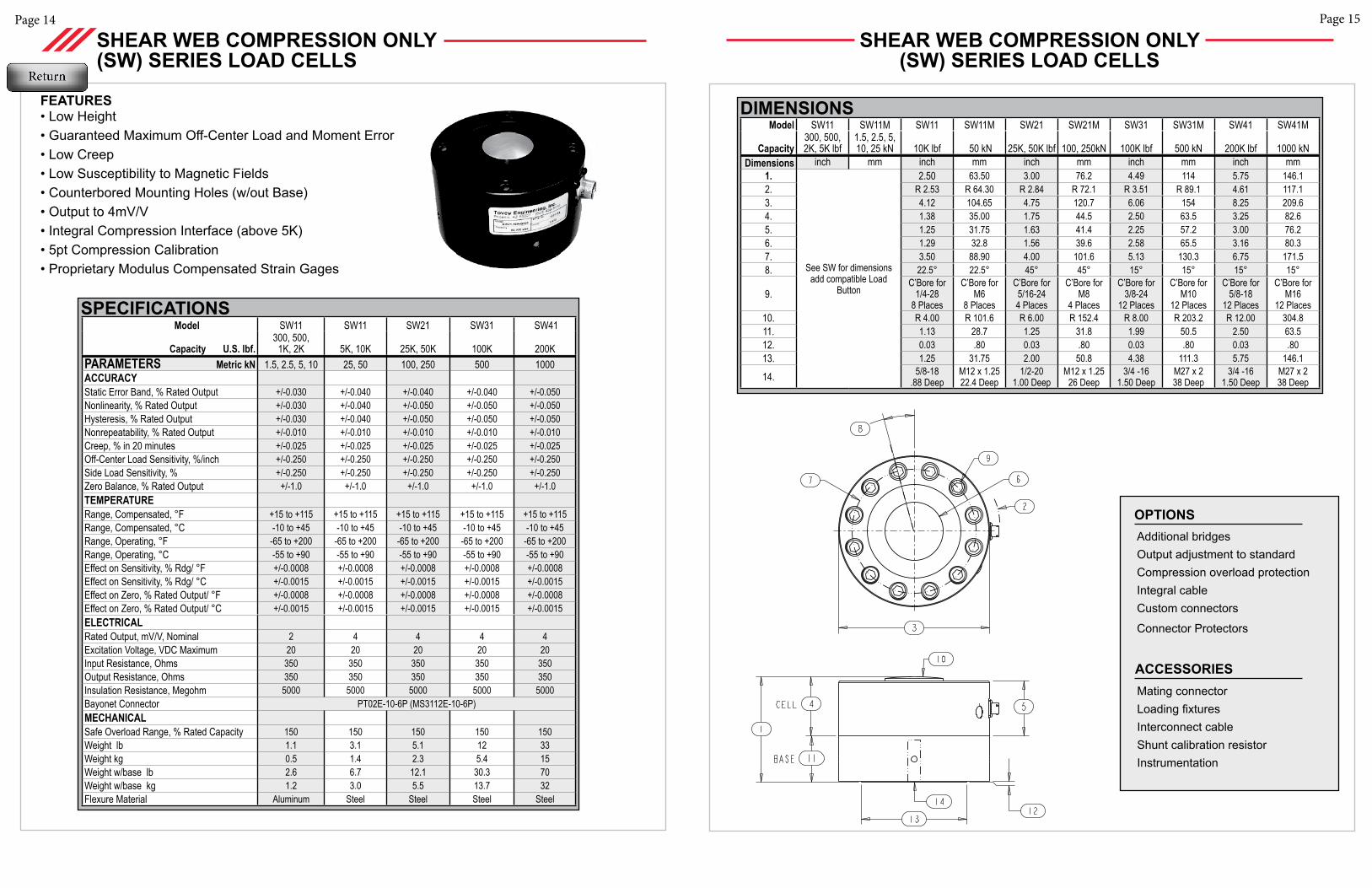
SPECIFICATIONS Model SW11 SW11 SW21 SW31 SW41
Capacity U.S. lbf.300, 500,
1K, 2K 5K, 10K 25K, 50K 100K 200KPARAMETERS Metric kN 1.5, 2.5, 5, 10 25, 50 100, 250 500 1000ACCURACY Static Error Band, % Rated Output +/-0.030 +/-0.040 +/-0.040 +/-0.040 +/-0.050Nonlinearity, % Rated Output +/-0.030 +/-0.040 +/-0.050 +/-0.050 +/-0.050Hysteresis, % Rated Output +/-0.030 +/-0.040 +/-0.050 +/-0.050 +/-0.050Nonrepeatability, % Rated Output +/-0.010 +/-0.010 +/-0.010 +/-0.010 +/-0.010Creep, % in 20 minutes +/-0.025 +/-0.025 +/-0.025 +/-0.025 +/-0.025Off-Center Load Sensitivity, %/inch +/-0.250 +/-0.250 +/-0.250 +/-0.250 +/-0.250Side Load Sensitivity, % +/-0.250 +/-0.250 +/-0.250 +/-0.250 +/-0.250Zero Balance, % Rated Output +/-1.0 +/-1.0 +/-1.0 +/-1.0 +/-1.0TEMPERATURERange, Compensated, °F +15 to +115 +15 to +115 +15 to +115 +15 to +115 +15 to +115Range, Compensated, °C -10 to +45 -10 to +45 -10 to +45 -10 to +45 -10 to +45Range, Operating, °F -65 to +200 -65 to +200 -65 to +200 -65 to +200 -65 to +200Range, Operating, °C -55 to +90 -55 to +90 -55 to +90 -55 to +90 -55 to +90Effect on Sensitivity, % Rdg/ °F +/-0.0008 +/-0.0008 +/-0.0008 +/-0.0008 +/-0.0008Effect on Sensitivity, % Rdg/ °C +/-0.0015 +/-0.0015 +/-0.0015 +/-0.0015 +/-0.0015Effect on Zero, % Rated Output/ °F +/-0.0008 +/-0.0008 +/-0.0008 +/-0.0008 +/-0.0008Effect on Zero, % Rated Output/ °C +/-0.0015 +/-0.0015 +/-0.0015 +/-0.0015 +/-0.0015ELECTRICALRated Output, mV/V, Nominal 2 4 4 4 4Excitation Voltage, VDC Maximum 20 20 20 20 20Input Resistance, Ohms 350 350 350 350 350Output Resistance, Ohms 350 350 350 350 350Insulation Resistance, Megohm 5000 5000 5000 5000 5000Bayonet Connector PT02E-10-6P (MS3112E-10-6P)MECHANICALSafe Overload Range, % Rated Capacity 150 150 150 150 150Weight lb 1.1 3.1 5.1 12 33Weight kg 0.5 1.4 2.3 5.4 15Weight w/base lb 2.6 6.7 12.1 30.3 70Weight w/base kg 1.2 3.0 5.5 13.7 32Flexure Material Aluminum Steel Steel Steel Steel
FEATURES• Low Height• Guaranteed Maximum Off-Center Load and Moment Error• Low Creep• Low Susceptibility to Magnetic Fields• Counterbored Mounting Holes (w/out Base)• Output to 4mV/V• Integral Compression Interface (above 5K)• 5pt Compression Calibration• Proprietary Modulus Compensated Strain Gages
SHEAR WEB COMPRESSION ONLY (SW) SERIES LOAD CELLS
SHEAR WEB COMPRESSION ONLY (SW) SERIES LOAD CELLS
Model SW11 SW11M SW11 SW11M SW21 SW21M SW31 SW31M SW41 SW41M
Capacity300, 500, 2K, 5K lbf
1.5, 2.5, 5, 10, 25 kN 10K lbf 50 kN 25K, 50K lbf 100, 250kN 100K lbf 500 kN 200K lbf 1000 kN
Dimensions inch mm inch mm inch mm inch mm inch mm1.
See SW for dimensions add compatible Load
Button
2.50 63.50 3.00 76.2 4.49 114 5.75 146.12. R 2.53 R 64.30 R 2.84 R 72.1 R 3.51 R 89.1 4.61 117.13. 4.12 104.65 4.75 120.7 6.06 154 8.25 209.64. 1.38 35.00 1.75 44.5 2.50 63.5 3.25 82.65. 1.25 31.75 1.63 41.4 2.25 57.2 3.00 76.26. 1.29 32.8 1.56 39.6 2.58 65.5 3.16 80.37. 3.50 88.90 4.00 101.6 5.13 130.3 6.75 171.58. 22.5° 22.5° 45° 45° 15° 15° 15° 15°
9.C’Bore for
1/4-288 Places
C’Bore for M6
8 Places
C’Bore for 5/16-244 Places
C’Bore for M8
4 Places
C’Bore for 3/8-24
12 Places
C’Bore for M10
12 Places
C’Bore for 5/8-18
12 Places
C’Bore for M16
12 Places10. R 4.00 R 101.6 R 6.00 R 152.4 R 8.00 R 203.2 R 12.00 304.811. 1.13 28.7 1.25 31.8 1.99 50.5 2.50 63.512. 0.03 .80 0.03 .80 0.03 .80 0.03 .8013. 1.25 31.75 2.00 50.8 4.38 111.3 5.75 146.1
14. 5/8-18.88 Deep
M12 x 1.25 22.4 Deep
1/2-201.00 Deep
M12 x 1.2526 Deep
3/4 -161.50 Deep
M27 x 238 Deep
3/4 -161.50 Deep
M27 x 238 Deep
Additional bridgesOutput adjustment to standardCompression overload protectionIntegral cableCustom connectors
Connector Protectors
OPTIONS
Mating connectorLoading fixturesInterconnect cableShunt calibration resistorInstrumentation
ACCESSORIES
DIMENSIONS
Page 17Page 16
© 2011 Tovey Engineering, Inc.
DIMENSIONS Model 2202
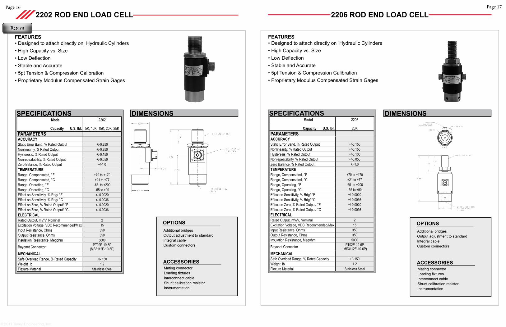
Capacity U.S. lbf. 5K, 10K, 15K, 20K, 25KPARAMETERS ACCURACY Static Error Band, % Rated Output +/-0.250Nonlinearity, % Rated Output +/-0.250Hysteresis, % Rated Output +/-0.150Nonrepeatability, % Rated Output +/-0.050Zero Balance, % Rated Output +/-1.0TEMPERATURERange, Compensated, °F +70 to +170Range, Compensated, °C +21 to +77Range, Operating, °F -65 to +200Range, Operating, °C -55 to +90Effect on Sensitivity, % Rdg/ °F +/-0.0020Effect on Sensitivity, % Rdg/ °C +/-0.0036Effect on Zero, % Rated Output/ °F +/-0.0020Effect on Zero, % Rated Output/ °C +/-0.0036ELECTRICALRated Output, mV/V, Nominal 2Excitation Voltage, VDC Recommended/Max 15Input Resistance, Ohms 350Output Resistance, Ohms 350Insulation Resistance, Megohm 5000
Bayonet Connector PT02E-10-6P (MS3112E-10-6P)
MECHANICALSafe Overload Range, % Rated Capacity +/- 150Weight lb 1.2Flexure Material Stainless Steel
SPECIFICATIONS
FEATURES• Designed to attach directly on Hydraulic Cylinders• High Capacity vs. Size• Low Deflection• Stable and Accurate• 5pt Tension & Compression Calibration• Proprietary Modulus Compensated Strain Gages
2202 ROD END LOAD CELL
Additional bridgesOutput adjustment to standardIntegral cableCustom connectors
OPTIONS
Mating connectorLoading fixturesInterconnect cableShunt calibration resistorInstrumentation
ACCESSORIES
2206 ROD END LOAD CELL
FEATURES• Designed to attach directly on Hydraulic Cylinders• High Capacity vs. Size• Low Deflection• Stable and Accurate• 5pt Tension & Compression Calibration• Proprietary Modulus Compensated Strain Gages
Additional bridgesOutput adjustment to standardIntegral cableCustom connectors
OPTIONS
Mating connectorLoading fixturesInterconnect cableShunt calibration resistorInstrumentation
ACCESSORIES
DIMENSIONS Model 2206
Capacity U.S. lbf. 25KPARAMETERS ACCURACY Static Error Band, % Rated Output +/-0.150Nonlinearity, % Rated Output +/-0.150Hysteresis, % Rated Output +/-0.100Nonrepeatability, % Rated Output +/-0.050Zero Balance, % Rated Output +/-1.0TEMPERATURERange, Compensated, °F +70 to +170Range, Compensated, °C +21 to +77Range, Operating, °F -65 to +200Range, Operating, °C -55 to +90Effect on Sensitivity, % Rdg/ °F +/-0.0020Effect on Sensitivity, % Rdg/ °C +/-0.0036Effect on Zero, % Rated Output/ °F +/-0.0020Effect on Zero, % Rated Output/ °C +/-0.0036ELECTRICALRated Output, mV/V, Nominal 2Excitation Voltage, VDC Recommended/Max 15Input Resistance, Ohms 350Output Resistance, Ohms 350Insulation Resistance, Megohm 5000
Bayonet Connector PT02E-10-6P (MS3112E-10-6P)
MECHANICALSafe Overload Range, % Rated Capacity +/- 150Weight lb 1.2Flexure Material Stainless Steel
SPECIFICATIONS
Page 19Page 18
Additional bridgesOutput adjustment to standardCompression overload protectionIntegral cableCustom connectors
Connector Protectors
Base
OPTIONS
Mating connectorLoading fixturesInterconnect cableShunt calibration resistorInstrumentation
ACCESSORIES
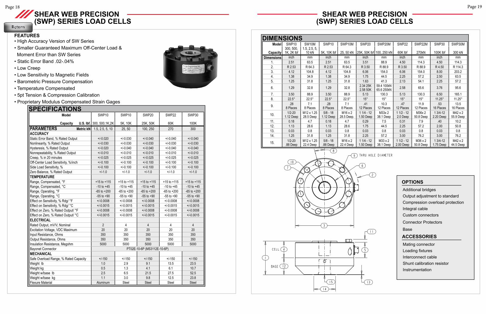
SPECIFICATIONS Model SWP10 SWP10 SWP20 SWP22 SWP30
Capacity U.S. lbf. 300, 500,1K,2K 5K, 10K 25K, 50K 60K 100KPARAMETERS Metric kN 1.5, 2.5, 5, 10 25, 50 100, 250 270 300ACCURACY Static Error Band, % Rated Output +/-0.020 +/-0.030 +/-0.040 +/-0.040 +/-0.040Nonlinearity, % Rated Output +/-0.030 +/-0.030 +/-0.030 +/-0.030 +/-0.030Hysteresis, % Rated Output +/-0.020 +/-0.040 +/-0.040 +/-0.040 +/-0.040Nonrepeatability, % Rated Output +/-0.010 +/-0.010 +/-0.010 +/-0.010 +/-0.010Creep, % in 20 minutes +/-0.025 +/-0.025 +/-0.025 +/-0.025 +/-0.025Off-Center Load Sensitivity, %/inch +/-0.100 +/-0.100 +/-0.100 +/-0.100 +/-0.100Side Load Sensitivity, % +/-0.100 +/-0.100 +/-0.100 +/-0.100 +/-0.100Zero Balance, % Rated Output +/-1.0 +/-1.0 +/-1.0 +/-1.0 +/-1.0TEMPERATURERange, Compensated, °F +15 to +115 +15 to +115 +15 to +115 +15 to +115 +15 to +115Range, Compensated, °C -10 to +45 -10 to +45 -10 to +45 -10 to +45 -10 to +45Range, Operating, °F -65 to +200 -65 to +200 -65 to +200 -65 to +200 -65 to +200Range, Operating, °C -55 to +90 -55 to +90 -55 to +90 -55 to +90 -55 to +90Effect on Sensitivity, % Rdg/ °F +/-0.0008 +/-0.0008 +/-0.0008 +/-0.0008 +/-0.0008Effect on Sensitivity, % Rdg/ °C +/-0.0015 +/-0.0015 +/-0.0015 +/-0.0015 +/-0.0015Effect on Zero, % Rated Output/ °F +/-0.0008 +/-0.0008 +/-0.0008 +/-0.0008 +/-0.0008Effect on Zero, % Rated Output/ °C +/-0.0015 +/-0.0015 +/-0.0015 +/-0.0015 +/-0.0015ELECTRICALRated Output, mV/V, Nominal 2 4 4 4 4Excitation Voltage, VDC Maximum 20 20 20 20 20Input Resistance, Ohms 350 350 350 350 350Output Resistance, Ohms 350 350 350 350 350Insulation Resistance, Megohm 5000 5000 5000 5000 5000Bayonet Connector PT02E-10-6P (MS3112E-10-6P)MECHANICALSafe Overload Range, % Rated Capacity +/-150 +/-150 +/-150 +/-150 +/-150Weight lb 1.0 2.9 9.1 13.5 23.5Weight kg 0.5 1.3 4.1 6.1 10.7 Weight w/base lb 2.5 6.5 21.5 27.5 52.5Weight w/base kg 1.1 3.0 9.8 12.5 23.8 Flexure Material Aluminum Steel Steel Steel Steel
SHEAR WEB PRECISION (SWP) SERIES LOAD CELLS
FEATURES• High Accuracy Version of SW Series• Smaller Guaranteed Maximum Off-Center Load & Moment Error than SW Series• Static Error Band .02-.04%• Low Creep• Low Sensitivity to Magnetic Fields• Barometric Pressure Compensation• Temperature Compensated• 5pt Tension & Compression Calibration• Proprietary Modulus Compensated Strain Gages
SHEAR WEB PRECISION (SWP) SERIES LOAD CELLS
Model SWP10 SW10M SWP10 SWP10M SWP20 SWP20M SWP22 SWP22M SWP30 SWP30M
Capacity300, 500, 1K, 2K lbf
1.5, 2.5, 5, 10 kN 5K, 10K lbf 25, 50 kN 25K, 50K lbf 100, 250 kN 60K lbf 270kN 100K lbf 300 kN
Dimensions inch mm inch mm inch mm inch mm inch mm1. 2.51 63.5 2.51 63.5 3.51 88.9 4.50 114.3 4.50 114.32. R 2.53 R 64.3 R 2.53 R 64.3 R 3.50 R 88.9 R 3.50 R 88.9 R 4.50 R 114.33. 4.12 104.8 4.12 104.8 6.06 154.0 6.06 154.0 8.00 203.24. 1.38 34.9 1.38 34.9 1.75 44.5 2.25 57.2 2.50 63.55. 1.25 31.8 1.25 31.8 1.63 41.3 2.13 54.1 2.25 57.2
6. 1.29 32.8 1.29 32.8 2.34 25K2.58 50K
59.4 100kN 65.6 250kN 2.58 65.6 3.76 95.6
7. 3.50 88.9 3.50 88.9 5.13 130.3 5.13 130.3 6.50 165.18. 22.5° 22.5° 22.5° 22.5° 15° 15° 15° 15° 11.25° 11.25°
9. .288 Places
7.18 Places
.288 Places
7.18 Places
.4112 Places
10.312 Places
.4712 Places
11.912 Places
.5316 Places
13.516 Places
10. 1/2-201.12 Deep
M12 x 1.2528.5 Deep
5/8 - 181.12 Deep
M16 x 228.5 Deep.
1 1/4 - 121.50 Deep
M33x 238.1 Deep
1 1/2 - 12 2.0 Deep
M36x 250.8 Deep
1 3/4-12 2.20 Deep
M42 x 255.9 Deep
11. 0.18 4.7 0.18 4.7 0.29 7.5 0.31 7.9 .40 10.212. 1.13 28.6 1.13 28.6 1.75 44.5 2.25 57.2 2.00 50.813. 0.03 0.8 0.03 0.8 0.03 0.8 0.03 0.8 0.03 0.814. 1.25 31.8 1.25 31.8 2.25 57.2 3.00 76.2 3.00 76.2
15. 1/2-20.88 Deep
M12 x 1.25 22.4 Deep
5/8 - 18 .88 Deep
M16 x 222.4 Deep
1 1/4 - 12 1.50 Deep
M33 x 238.1 Deep
1 1/2 - 12 2.00 Deep
M36 x 250.8 Deep
1 3/4-121.75 Deep
M42 x 2 44.5 Deep
DIMENSIONS
Page 21Page 20
Additional bridgesOutput adjustment to standardCompression overload protectionIntegral cableCustom connectors
Connector Protectors
Base
OPTIONS
Mating connectorLoading fixturesInterconnect cableShunt calibration resistorInstrumentation
ACCESSORIES
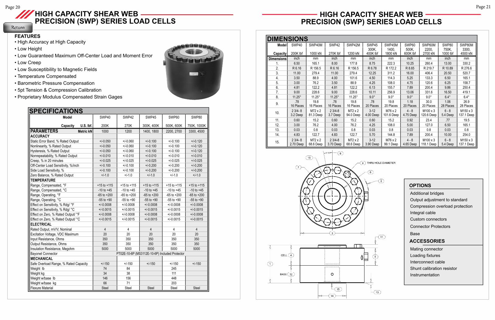
Model SWP40 SWP42 SWP45 SWP60 SWP80
Capacity U.S. lbf. 200K 270K 300K, 400K 500K, 600K 750K, 1000KPARAMETERS Metric kN 1000 1200 1400, 1800 2200, 2700 3300, 4500ACCURACY Static Error Band, % Rated Output +/-0.050 +/-0.060 +/-0.100 +/-0.100 +/-0.120Nonlinearity, % Rated Output +/-0.050 +/-0.060 +/-0.100 +/-0.100 +/-0.120Hysteresis, % Rated Output +/-0.050 +/-0.060 +/-0.100 +/-0.100 +/-0.120Nonrepeatability, % Rated Output +/-0.010 +/-0.010 +/-0.010 +/-0.010 +/-0.010Creep, % in 20 minutes +/-0.025 +/-0.025 +/-0.025 +/-0.025 +/-0.025Off-Center Load Sensitivity, %/inch +/-0.100 +/-0.100 +/-0.200 +/-0.200 +/-0.200Side Load Sensitivity, % +/-0.100 +/-0.100 +/-0.200 +/-0.200 +/-0.200Zero Balance, % Rated Output +/-1.0 +/-1.0 +/-1.0 +/-1.0 +/-1.0TEMPERATURERange, Compensated, °F +15 to +115 +15 to +115 +15 to +115 +15 to +115 +15 to +115Range, Compensated, °C -10 to +45 -10 to +45 -10 to +45 -10 to +45 -10 to +45Range, Operating, °F -65 to +200 -65 to +200 -65 to +200 -65 to +200 -65 to +200Range, Operating, °C -55 to +90 -55 to +90 -55 to +90 -55 to +90 -55 to +90Effect on Sensitivity, % Rdg/ °F +/-0.0008 +/-0.0008 +/-0.0008 +/-0.0008 +/-0.0008Effect on Sensitivity, % Rdg/ °C +/-0.0015 +/-0.0015 +/-0.0015 +/-0.0015 +/-0.0015Effect on Zero, % Rated Output/ °F +/-0.0008 +/-0.0008 +/-0.0008 +/-0.0008 +/-0.0008Effect on Zero, % Rated Output/ °C +/-0.0015 +/-0.0015 +/-0.0015 +/-0.0015 +/-0.0015ELECTRICALRated Output, mV/V, Nominal 4 4 4 4 4Excitation Voltage, VDC Maximum 20 20 20 20 20Input Resistance, Ohms 350 350 350 350 350Output Resistance, Ohms 350 350 350 350 350Insulation Resistance, Megohm 5000 5000 5000 5000 5000Bayonet Connector PT02E-10-6P (MS3112E-10-6P) Included ProtectorMECHANICALSafe Overload Range, % Rated Capacity +/-150 +/-150 +/-150 +/-150 +/-150Weight lb 74 84 245Weight kg 34 38 111Weight w/base lb 146 156 448Weight w/base kg 66 71 203 Flexure Material Steel Steel Steel Steel Steel
FEATURES• High Accuracy at High Capacity• Low Height• Low Guaranteed Maximum Off-Center Load and Moment Error• Low Creep• Low Susceptibility to Magnetic Fields• Temperature Compensated• Barometric Pressure Compensation• 5pt Tension & Compression Calibration• Proprietary Modulus Compensated Strain Gages
HIGH CAPACITY SHEAR WEB PRECISION (SWP) SERIES LOAD CELLS
SPECIFICATIONS
HIGH CAPACITY SHEAR WEB PRECISION (SWP) SERIES LOAD CELLS
Model SWP40 SWP40M SWP42 SWP42M SWP45 SWP45M SWP60 SWP60M SWP80 SWP80M
Capacity 200K lbf 1000 kN 270K lbf 1200 kN300K,
400K lbf1400,
1800 kN500K,
600K lbf2200,
2700 kN750K,
1000 lbf3300,
4500 kNDimensions inch mm inch mm inch mm inch mm inch mm
1. 6.50 165.1 8.00 177.8 8.75 222.3 10.25 260.4 13.00 330.22. R 6.16 R 156.5 R 6.16 R 156.5 R 6.78 R 172.2 R 8.65 R 219.7 R 10.89 R 276.63. 11.00 279.4 11.00 279.4 12.25 311.2 16.00 406.4 20.50 520.74. 3.50 88.9 4.00 101.6 4.50 114.3 5.25 133.3 6.50 165.15. 3.00 76.2 3.50 88.9 4.25 108.0 4.75 120.6 6.25 158.76. 4.81 122.2 4.81 122.2 6.13 155.7 7.89 200.4 9.86 250.47. 9.00 228.6 9.00 228.6 10.11 256.9 13.06 331.6 16.50 419.18. 11.25° 11.25° 11.25° 11.25° 9.0° 9.0° 9.0° 9.0° 6.4° 6.4°
9. .78 16 Places
19.816 Places
.7816 Places
19.816 Places
.7820 Places
19.820 Places
1.1820 Places
30.020 Places
1.0628 Places
26.928 Places
10. 2 3/4- 8 3.2 Deep
M72 x 281.3 Deep
2 3/4-83.7 Deep
M72 x 294.0 Deep
3-124.00 Deep
M76 x 2101.6 Deep
4 - 84.75 Deep
M100 x 3120.6 Deep
6 - 85.4 Deep
M150 x 3137.1 Deep
11. 0.60 15.2 0.60 15.2 0.60 15.2 0.92 23.4 .77 19.512. 3.00 76.2 4.00 76.2 4.25 108.0 5.00 127.0 6.50 165.113. 0.03 0.8 0.03 0.8 0.03 0.8 0.03 0.8 0.03 0.814. 4.83 122.7 4.83 122.7 5.70 144.8 7.89 200.4 10.00 254.0
15. 2 3/4- 82.70 Deep
M72 x 2 68.6 Deep
2 3/4-8 3.70 Deep
M72 x 2 68.6 Deep
3-123.90 Deep
M76 x 299.1 Deep
4 - 84.65 Deep
M100 x 3118.1 Deep
6 - 85.4 Deep
M150 x 3137.1 Deep
DIMENSIONS
Page 22
© 2011 Tovey Engineering, Inc.
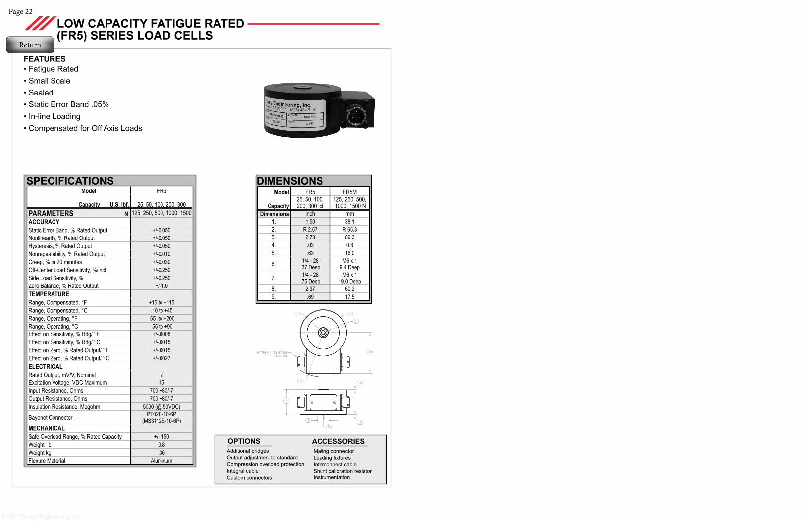
DIMENSIONSModel FR5 FR5M
Capacity25, 50, 100, 200, 300 lbf
125, 250, 500, 1000, 1500 N
Dimensions inch mm1. 1.50 38.12. R 2.57 R 65.33. 2.73 69.34. .03 0.85. .63 16.0
6. 1/4 - 28 .37 Deep
M6 x 19.4 Deep
7. 1/4 - 28 .75 Deep
M6 x 1 19.0 Deep
8. 2.37 60.29. .69 17.5
Model FR5
Capacity U.S. lbf. 25, 50, 100, 200, 300PARAMETERS N 125, 250, 500, 1000, 1500ACCURACY Static Error Band, % Rated Output +/-0.050Nonlinearity, % Rated Output +/-0.050Hysteresis, % Rated Output +/-0.050Nonrepeatability, % Rated Output +/-0.010Creep, % in 20 minutes +/-0.030Off-Center Load Sensitivity, %/inch +/-0.250Side Load Sensitivity, % +/-0.250Zero Balance, % Rated Output +/-1.0TEMPERATURERange, Compensated, °F +15 to +115Range, Compensated, °C -10 to +45Range, Operating, °F -65 to +200Range, Operating, °C -55 to +90Effect on Sensitivity, % Rdg/ °F +/-.0008Effect on Sensitivity, % Rdg/ °C +/-.0015Effect on Zero, % Rated Output/ °F +/-.0015Effect on Zero, % Rated Output/ °C +/-.0027ELECTRICALRated Output, mV/V, Nominal 2Excitation Voltage, VDC Maximum 15Input Resistance, Ohms 700 +80/-7Output Resistance, Ohms 700 +80/-7Insulation Resistance, Megohm 5000 (@ 50VDC)
Bayonet Connector PT02E-10-6P (MS3112E-10-6P)
MECHANICALSafe Overload Range, % Rated Capacity +/- 150Weight lb 0.8Weight kg .36Flexure Material Aluminum
SPECIFICATIONS
FEATURES• Fatigue Rated • Small Scale• Sealed • Static Error Band .05%• In-line Loading • Compensated for Off Axis Loads
LOW CAPACITY FATIGUE RATED (FR5) SERIES LOAD CELLS
Additional bridgesOutput adjustment to standardCompression overload protectionIntegral cable Custom connectors
OPTIONS Mating connectorLoading fixturesInterconnect cableShunt calibration resistorInstrumentation
ACCESSORIES
Page 25Page 24
Additional bridgesOutput adjustment to standardCompression overload protectionIntegral cableCustom connectors
Connector Protectors
Base
OPTIONS
Mating connectorLoading fixturesInterconnect cableShunt calibration resistorInstrumentation
ACCESSORIES
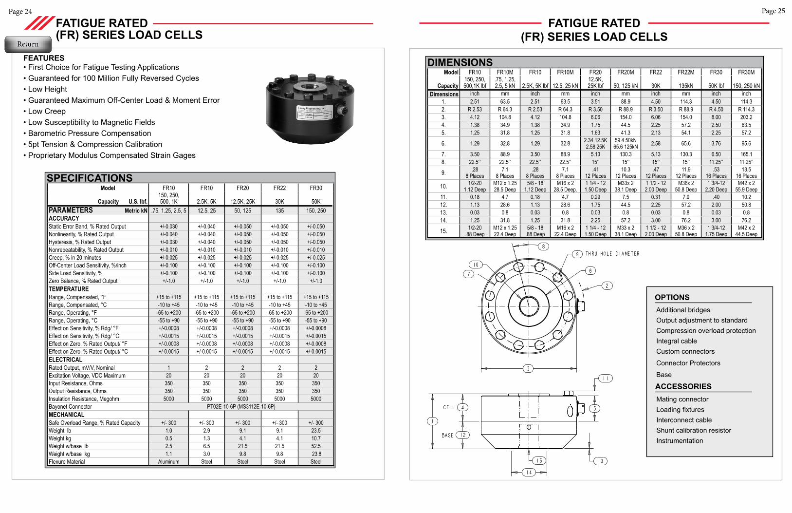
FATIGUE RATED (FR) SERIES LOAD CELLS
Model FR10 FR10 FR20 FR22 FR30
Capacity U.S. lbf.150, 250, 500, 1K 2.5K, 5K 12.5K, 25K 30K 50K
PARAMETERS Metric kN .75, 1.25, 2.5, 5 12.5, 25 50, 125 135 150, 250ACCURACY Static Error Band, % Rated Output +/-0.030 +/-0.040 +/-0.050 +/-0.050 +/-0.050Nonlinearity, % Rated Output +/-0.040 +/-0.040 +/-0.050 +/-0.050 +/-0.050Hysteresis, % Rated Output +/-0.030 +/-0.040 +/-0.050 +/-0.050 +/-0.050Nonrepeatability, % Rated Output +/-0.010 +/-0.010 +/-0.010 +/-0.010 +/-0.010Creep, % in 20 minutes +/-0.025 +/-0.025 +/-0.025 +/-0.025 +/-0.025Off-Center Load Sensitivity, %/inch +/-0.100 +/-0.100 +/-0.100 +/-0.100 +/-0.100Side Load Sensitivity, % +/-0.100 +/-0.100 +/-0.100 +/-0.100 +/-0.100Zero Balance, % Rated Output +/-1.0 +/-1.0 +/-1.0 +/-1.0 +/-1.0TEMPERATURERange, Compensated, °F +15 to +115 +15 to +115 +15 to +115 +15 to +115 +15 to +115Range, Compensated, °C -10 to +45 -10 to +45 -10 to +45 -10 to +45 -10 to +45Range, Operating, °F -65 to +200 -65 to +200 -65 to +200 -65 to +200 -65 to +200Range, Operating, °C -55 to +90 -55 to +90 -55 to +90 -55 to +90 -55 to +90Effect on Sensitivity, % Rdg/ °F +/-0.0008 +/-0.0008 +/-0.0008 +/-0.0008 +/-0.0008Effect on Sensitivity, % Rdg/ °C +/-0.0015 +/-0.0015 +/-0.0015 +/-0.0015 +/-0.0015Effect on Zero, % Rated Output/ °F +/-0.0008 +/-0.0008 +/-0.0008 +/-0.0008 +/-0.0008Effect on Zero, % Rated Output/ °C +/-0.0015 +/-0.0015 +/-0.0015 +/-0.0015 +/-0.0015ELECTRICALRated Output, mV/V, Nominal 1 2 2 2 2Excitation Voltage, VDC Maximum 20 20 20 20 20Input Resistance, Ohms 350 350 350 350 350Output Resistance, Ohms 350 350 350 350 350Insulation Resistance, Megohm 5000 5000 5000 5000 5000Bayonet Connector PT02E-10-6P (MS3112E-10-6P)MECHANICALSafe Overload Range, % Rated Capacity +/- 300 +/- 300 +/- 300 +/- 300 +/- 300Weight lb 1.0 2.9 9.1 9.1 23.5Weight kg 0.5 1.3 4.1 4.1 10.7Weight w/base lb 2.5 6.5 21.5 21.5 52.5Weight w/base kg 1.1 3.0 9.8 9.8 23.8Flexure Material Aluminum Steel Steel Steel Steel
FEATURES• First Choice for Fatigue Testing Applications• Guaranteed for 100 Million Fully Reversed Cycles• Low Height• Guaranteed Maximum Off-Center Load & Moment Error• Low Creep• Low Susceptibility to Magnetic Fields• Barometric Pressure Compensation• 5pt Tension & Compression Calibration• Proprietary Modulus Compensated Strain Gages
SPECIFICATIONS
FATIGUE RATED (FR) SERIES LOAD CELLS
DIMENSIONSModel FR10 FR10M FR10 FR10M FR20 FR20M FR22 FR22M FR30 FR30M
Capacity150, 250, 500,1K lbf
.75, 1.25, 2.5, 5 kN 2.5K, 5K lbf 12.5, 25 kN
12.5K, 25K lbf 50, 125 kN 30K 135kN 50K lbf 150, 250 kN
Dimensions inch mm inch mm inch mm inch mm inch inch1. 2.51 63.5 2.51 63.5 3.51 88.9 4.50 114.3 4.50 114.32. R 2.53 R 64.3 R 2.53 R 64.3 R 3.50 R 88.9 R 3.50 R 88.9 R 4.50 R 114.33. 4.12 104.8 4.12 104.8 6.06 154.0 6.06 154.0 8.00 203.24. 1.38 34.9 1.38 34.9 1.75 44.5 2.25 57.2 2.50 63.55. 1.25 31.8 1.25 31.8 1.63 41.3 2.13 54.1 2.25 57.2
6. 1.29 32.8 1.29 32.8 2.34 12.5K2.58 25K
59.4 50kN 65.6 125kN 2.58 65.6 3.76 95.6
7. 3.50 88.9 3.50 88.9 5.13 130.3 5.13 130.3 6.50 165.18. 22.5° 22.5° 22.5° 22.5° 15° 15° 15° 15° 11.25° 11.25°
9. .288 Places
7.18 Places
.288 Places
7.18 Places
.4112 Places
10.312 Places
.4712 Places
11.912 Places
.5316 Places
13.516 Places
10. 1/2-201.12 Deep
M12 x 1.2528.5 Deep
5/8 - 181.12 Deep
M16 x 228.5 Deep.
1 1/4 - 121.50 Deep
M33x 238.1 Deep
1 1/2 - 122.00 Deep
M36x 250.8 Deep
1 3/4-12 2.20 Deep
M42 x 255.9 Deep
11. 0.18 4.7 0.18 4.7 0.29 7.5 0.31 7.9 .40 10.212. 1.13 28.6 1.13 28.6 1.75 44.5 2.25 57.2 2.00 50.813. 0.03 0.8 0.03 0.8 0.03 0.8 0.03 0.8 0.03 0.814. 1.25 31.8 1.25 31.8 2.25 57.2 3.00 76.2 3.00 76.2
15. 1/2-20.88 Deep
M12 x 1.25 22.4 Deep
5/8 - 18 .88 Deep
M16 x 222.4 Deep
1 1/4 - 12 1.50 Deep
M33 x 238.1 Deep
1 1/2 - 12 2.00 Deep
M36 x 250.8 Deep
1 3/4-121.75 Deep
M42 x 2 44.5 Deep
Page 27Page 26
Additional bridgesOutput adjustment to standardCompression overload protectionIntegral cableCustom connectors
Connector Protectors
Base
OPTIONS
Mating connectorLoading fixturesInterconnect cableShunt calibration resistorInstrumentation
ACCESSORIES
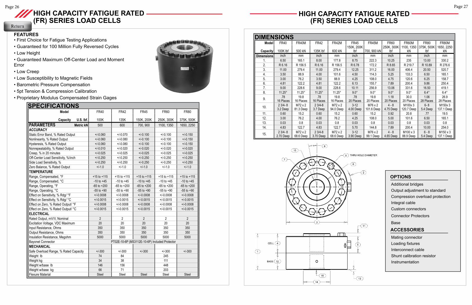
SPECIFICATIONS Model FR40 FR42 FR45 FR60 FR80
Capacity U.S. lbf. 100K 135K 150K, 200K 250K, 300K 375K, 500KPARAMETERS Metric kN 500 600 700, 900 1100, 1350 1650, 2250ACCURACY Static Error Band, % Rated Output +/-0.060 +/-0.070 +/-0.100 +/-0.100 +/-0.150Nonlinearity, % Rated Output +/-0.060 +/-0.080 +/-0.100 +/-0.100 +/-0.150Hysteresis, % Rated Output +/-0.060 +/-0.080 +/-0.100 +/-0.100 +/-0.150Nonrepeatability, % Rated Output +/-0.010 +/-0.020 +/-0.020 +/-0.020 +/-0.020Creep, % in 20 minutes +/-0.025 +/-0.025 +/-0.025 +/-0.025 +/-0.025Off-Center Load Sensitivity, %/inch +/-0.250 +/-0.250 +/-0.250 +/-0.250 +/-0.250Side Load Sensitivity, % +/-0.250 +/-0.250 +/-0.250 +/-0.250 +/-0.250Zero Balance, % Rated Output +/-1.0 +/-1.0 +/-1.0 +/-1.0 +/-1.0TEMPERATURERange, Compensated, °F +15 to +115 +15 to +115 +15 to +115 +15 to +115 +15 to +115Range, Compensated, °C -10 to +45 -10 to +45 -10 to +45 -10 to +45 -10 to +45Range, Operating, °F -65 to +200 -65 to +200 -65 to +200 -65 to +200 -65 to +200Range, Operating, °C -55 to +90 -55 to +90 -55 to +90 -55 to +90 -55 to +90Effect on Sensitivity, % Rdg/ °F +/-0.0008 +/-0.0008 +/-0.0008 +/-0.0008 +/-0.0008Effect on Sensitivity, % Rdg/ °C +/-0.0015 +/-0.0015 +/-0.0015 +/-0.0015 +/-0.0015Effect on Zero, % Rated Output/ °F +/-0.0008 +/-0.0008 +/-0.0008 +/-0.0008 +/-0.0008Effect on Zero, % Rated Output/ °C +/-0.0015 +/-0.0015 +/-0.0015 +/-0.0015 +/-0.0015ELECTRICALRated Output, mV/V, Nominal 2 2 2 2 2Excitation Voltage, VDC Maximum 20 20 20 20 20Input Resistance, Ohms 350 350 350 350 350Output Resistance, Ohms 350 350 350 350 350Insulation Resistance, Megohm 5000 5000 5000 5000 5000Bayonet Connector PT02E-10-6P (MS3112E-10-6P) Included ProtectorMECHANICALSafe Overload Range, % Rated Capacity +/-300 +/-300 +/-300 +/-300 +/-300Weight lb 74 84 245Weight kg 34 38 111Weight w/base lb 146 156 448Weight w/base kg 66 71 203Flexure Material Steel Steel Steel Steel Steel
FEATURES• First Choice for Fatigue Testing Applications• Guaranteed for 100 Million Fully Reversed Cycles• Low Height• Guaranteed Maximum Off-Center Load and Moment Error• Low Creep• Low Susceptibility to Magnetic Fields• Barometric Pressure Compensation• 5pt Tension & Compression Calibration• Proprietary Modulus Compensated Strain Gages
HIGH CAPACITY FATIGUE RATED (FR) SERIES LOAD CELLS
Model FR40 FR40M FR42 FR42M FR45 FR45M FR60 FR60M FR80 FR80M
Capacity 100K lbf 500 kN 135K lbf 600 kN150K, 200K
lbf 700, 900 kN250K, 300K
lbf1100, 1350
kN375K, 500K
lbf1650, 2250
kNDimensions inch mm inch mm inch mm inch mm inch mm
1. 6.50 165.1 8.00 177.8 8.75 222.3 10.25 235 13.00 330.22. R 6.16 R 156.5 R 6.16 R 156.5 R 6.78 172.2 R 8.65 R 219.7 R 10.89 R 276.63. 11.00 279.4 11.00 279.4 12.25 311.2 16.00 406.4 20.50 520.74. 3.50 88.9 4.00 101.6 4.50 114.3 5.25 133.3 6.50 165.15. 3.00 76.2 3.50 88.9 4.25 108.0 4.75 120.6 6.25 158.76. 4.81 122.2 4.81 122.2 6.13 155.7 7.89 200.4 9.86 250.47. 9.00 228.6 9.00 228.6 10.11 256.9 13.06 331.6 16.50 419.18. 11.25° 11.25° 11.25° 11.25° 9.0° 9.0° 9.0° 9.0° 6.4° 6.4°
9. .78 16 Places
19.816 Places
.7816 Places
19.816 Places
.7820 Places
19.820 Places
1.1820 Places
30.020 Places
1.0628 Places
26.928 Places
10. 2 3/4- 8 3.2 Deep
M72 x 281.3 Deep
2 3/4-83.7 Deep
M72 x 294.0 Deep
3-124.00 Deep
M76 x 2101.6 Deep
4 - 84.75 Deep
M100x 3120.7 Deep
6- 85.4 Deep
M150x 3137.1 Deep
11. 0.60 15.2 0.60 15.2 0.60 15.2 0.92 20.8 .77 19.512. 3.00 76.2 4.00 76.2 4.25 108.0 5.00 101.6 6.50 165.113. 0.03 0.8 0.03 0.8 0.03 0.8 0.03 0.8 0.03 0.814. 4.83 122.7 4.83 122.7 5.70 144.8 7.89 200.4 10.00 254.0
15. 2 3/4- 82.70 Deep
M72 x 2 68.6 Deep
2 3/4-8 3.70 Deep
M72 x 2 68.6 Deep
3-123.90 Deep
M76 x 299.1 Deep
4 - 84.65 Deep
M100 x 388.9 Deep
6 - 85.4 Deep
M150 x 3137.1 Deep
HIGH CAPACITY FATIGUE RATED (FR) SERIES LOAD CELLS
DIMENSIONS
Page 29Page 28
SPECIFICATIONS
Additional bridgesOutput adjustment to standardCompression overload protectionIntegral cableCustom connectors
Connector Protectors
OPTIONS
Mating connectorLoading fixturesInterconnect cableShunt calibration resistorInstrumentation
ACCESSORIES
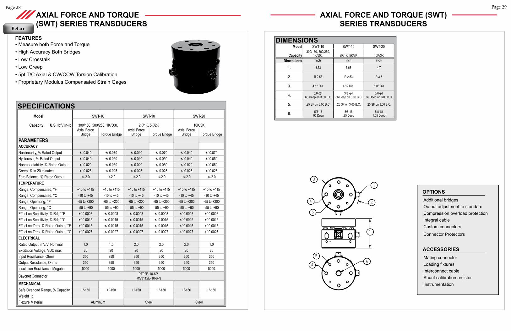
Model SWT-10 SWT-10 SWT-20
Capacity300/150, 500/250,
1K/500, 2K/1K, 5K/2K 10K/3KDimensions inch inch inch
1. 3.63 3.63 4.7
2. R 2.53 R 2.53 R 3.5
3. 4.12 Dia. 4.12 Dia. 6.06 Dia
4. 3/8 -24 .66 Deep on 3.00 B.C.
3/8 -24 .66 Deep on 3.00 B.C.
3/8-24 .66 Deep on 3.00 B.C.
5. .25 SF on 3.00 B.C. .25 SF on 3.00 B.C. .25 SF on 3.00 B.C.
6. 5/8-18 .95 Deep
5/8-18 .95 Deep
5/8-18 1.05 Deep
AXIAL FORCE AND TORQUE(SWT) SERIES TRANSDUCERS
AXIAL FORCE AND TORQUE (SWT) SERIES TRANSDUCERS
FEATURES• Measure both Force and Torque• High Accuracy Both Bridges• Low Crosstalk• Low Creep• 5pt T/C Axial & CW/CCW Torsion Calibration • Proprietary Modulus Compensated Strain Gages
1
2
37
5
4
5
4
6
Model SWT-10 SWT-10 SWT-20
Capacity U.S. lbf./ in-lb 300/150, 500/250, 1K/500, 2K/1K, 5K/2K 10K/3KAxial Force
Bridge Torque BridgeAxial Force
Bridge Torque BridgeAxial Force
Bridge Torque BridgePARAMETERS ACCURACY Nonlinearity, % Rated Output +/-0.040 +/-0.070 +/-0.040 +/-0.070 +/-0.040 +/-0.070Hysteresis, % Rated Output +/-0.040 +/-0.050 +/-0.040 +/-0.050 +/-0.040 +/-0.050Nonrepeatability, % Rated Output +/-0.020 +/-0.050 +/-0.020 +/-0.050 +/-0.020 +/-0.050Creep, % in 20 minutes +/-0.025 +/-0.025 +/-0.025 +/-0.025 +/-0.025 +/-0.025Zero Balance, % Rated Output +/-2.0 +/-2.0 +/-2.0 +/-2.0 +/-2.0 +/-2.0TEMPERATURERange, Compensated, °F +15 to +115 +15 to +115 +15 to +115 +15 to +115 +15 to +115 +15 to +115Range, Compensated, °C -10 to +45 -10 to +45 -10 to +45 -10 to +45 -10 to +45 -10 to +45Range, Operating, °F -65 to +200 -65 to +200 -65 to +200 -65 to +200 -65 to +200 -65 to +200Range, Operating, °C -55 to +90 -55 to +90 -55 to +90 -55 to +90 -55 to +90 -55 to +90Effect on Sensitivity, % Rdg/ °F +/-0.0008 +/-0.0008 +/-0.0008 +/-0.0008 +/-0.0008 +/-0.0008Effect on Sensitivity, % Rdg/ °C +/-0.0015 +/-0.0015 +/-0.0015 +/-0.0015 +/-0.0015 +/-0.0015Effect on Zero, % Rated Output/ °F +/-0.0015 +/-0.0015 +/-0.0015 +/-0.0015 +/-0.0015 +/-0.0015Effect on Zero, % Rated Output/ °C +/-0.0027 +/-0.0027 +/-0.0027 +/-0.0027 +/-0.0027 +/-0.0027ELECTRICALRated Output, mV/V, Nominal 1.0 1.5 2.0 2.5 2.0 1.0Excitation Voltage, VDC max 20 20 20 20 20 20Input Resistance, Ohms 350 350 350 350 350 350 Output Resistance, Ohms 350 350 350 350 350 350 Insulation Resistance, Megohm 5000 5000 5000 5000 5000 5000
Bayonet Connector PT02E-10-6P (MS3112E-10-6P)
MECHANICALSafe Overload Range, % Capacity +/-150 +/-150 +/-150 +/-150 +/-150 +/-150Weight lbFlexure Material Aluminum Steel Steel
SPECIFICATIONS
DIMENSIONS

Page 31Page 30
Additional bridgesOutput adjustment to standardCompression overload protectionIntegral cableCustom connectors
Connector Protectors
Base
OPTIONS
Mating connectorLoading fixturesInterconnect cableShunt calibration resistorInstrumentation
ACCESSORIES
DIMENSIONSModel SW10-XYZ SW10-XYZ SW20-XYZ SW30-XYZ
Capacity500/200, 1K/400,
2K/800 5K/1K,10K/2K25K/10K, 50K/20K 100K/50K
Dimensions inch inch inch inch1. 2.51 2.51 3.51 4.502. R 2.53 R 2.53 R 3.50 R 4.503. 4.12 4.12 6.06 8.004. 1.38 1.38 1.75 2.505. 1.25 1.25 1.63 2.25
6. 1.29 1.29 2.34 25K/10K2.58 50K/20K 3.76
7. 3.50 3.50 5.13 6.508. 22.5° 22.5° 15° 11.25°
9. .288 Places
.288 Places
.4112 Places
.5316 Places
10. 1/2-201.12 Deep
5/8-181.12 Deep
1 1/4 - 121.50 Deep
1 3/4-12 2.20 Deep
11. 0.18 0.18 0.29 .4012. 1.13 1.13 1.75 2.0013. 0.03 0.03 0.03 0.0314. 1.25 1.25 2.25 3.00
15. 1/2-20.88 Deep
5/8-18.88 Deep
1 1/4 - 12 1.50 Deep
1 3/4-121.75 Deep
AXIAL FORCE AND MOMENT (SW-XYZ) SERIES
AXIAL FORCE AND MOMENT (SW-XYZ) SERIES
SPECIFICATIONS
FEATURES• Measure Z-Axis Force, X- and Y-Axis Moment• High Accuracy Force Measurement • Proprietary Modulus Compensated Strain Gages
Model SW10-XYZ SW10-XYZ SW20-XYZ SW30-XYZ
Capacity U.S. lbf.500/200, 1K/400,
2K/800, 5K/1K, 10K/2K 25K/10K, 50K/20K 100K/50K
PARAMETERS Force-lbf Moment-
in-lbf Force-lbf Moment-
in-lbf Force-lbf Moment-
in-lbf Force-lbf Moment-
in-lbfACCURACY Static Error Band, % Rated Output +/-0.040 +/-1.0 +/-0.040 +/-1.0 +/-0.050 +/-1.0 +/-0.050 +/-1.0Nonlinearity, % Rated Output +/-0.030 +/-1.0 +/-0.030 +/-1.0 +/-0.050 +/-1.0 +/-0.050 +/-1.0Hysteresis, % Rated Output +/-0.040 +/-0.10 +/-0.040 +/-0.10 +/-0.050 +/-0.10 +/-0.050 +/-0.10Nonrepeatability, % Rated Output +/-0.010 +/-0.050 +/-0.010 +/-0.050 +/-0.010 +/-0.050 +/-0.010 +/-0.050Creep, % in 20 minutes +/-0.025 +/-0.025 +/-0.025 +/-0.025 +/-0.025 +/-0.025 +/-0.025 +/-0.025Off-Center Load Sensitivity, %/inch +/-0.250 +/-1.0 +/-0.250 +/-1.0 +/-0.250 +/-1.0 +/-0.250 +/-1.0Side Load Sensitivity, % +/-0.250 +/-1.0 +/-0.250 +/-1.0 +/-0.250 +/-1.0 +/-0.250 +/-1.0Zero Balance, % Rated Output +/-1.0 +/-1.0 +/-1.0 +/-1.0 +/-1.0 +/-1.0 +/-1.0 +/-1.0TEMPERATURERange, Compensated, °F +15 to +115 +15 to +115 +15 to +115 +15 to +115 +15 to +115 +15 to +115 +15 to +115 +15 to +115Range, Compensated, °C -10 to +45 -10 to +45 -10 to +45 -10 to +45 -10 to +45 -10 to +45 -10 to +45 -10 to +45Range, Operating, °F -65 to +200 -65 to +200 -65 to +200 -65 to +200 -65 to +200 -65 to +200 -65 to +200 -65 to +200Range, Operating, °C -55 to +90 -55 to +90 -55 to +90 -55 to +90 -55 to +90 -55 to +90 -55 to +90 -55 to +90Effect on Sensitivity, % Rdg/ °F +/-0.080 +/-0.080 +/-0.080 +/-0.080 +/-0.080 +/-0.080 +/-0.080 +/-0.080Effect on Sensitivity, % Rdg/ °C +/-0.150 +/-0.150 +/-0.150 +/-0.150 +/-0.150 +/-0.150 +/-0.150 +/-0.150Effect on Zero, % Rated Output/ °F +/-0.150 +/-0.150 +/-0.150 +/-0.150 +/-0.150 +/-0.150 +/-0.150 +/-0.150Effect on Zero, % Rated Output/ °C +/-0.270 +/-0.270 +/-0.270 +/-0.270 +/-0.270 +/-0.270 +/-0.270 +/-0.270ELECTRICALRated Output, mV/V, Nominal 2 1.5 4 1.5 4 1.5 4 1.5Excitation Voltage, VDC Maximum 10 10 10 10 10 10 10 10Input Resistance, Ohms 350 350 350 350 350 350 350 350Output Resistance, Ohms 350 350 350 350 350 350 350 350Insulation Resistance, Megohm 5000 5000 5000 5000 5000 5000 5000 5000Bayonet Connector PT02E-10-6P (MS3112E-10-6P)MECHANICALSafe Overload Range, % Rated Capacity +/-150 +/-150 +/-150 +/-150 +/-150 +/-150 +/-150 +/-150Weight lb 1.0 1.0 1.0 1.0 9.1 9.1 23.5 23.5Weight kg 0.45 0.45 0.45 0.45 4.13 4.13 10.66 10.66 Weight w/base lb 2.5 2.5 2.5 2.5 21.5 21.5 52.5 52.5Weight w/base kg 1.13 1.13 1.13 1.13 9.75 9.75 23.81 23.81 Flexure Material Aluminum Steel Steel Steel
Page 33Page 32
Additional bridges
Output adjustment to standard
Compression overload protection
Integral cable
Custom connectors
Connector Protectors
OPTIONS
Mating connector
Loading fixtures
Interconnect cable
Shunt calibration resistor
Instrumentation
ACCESSORIES
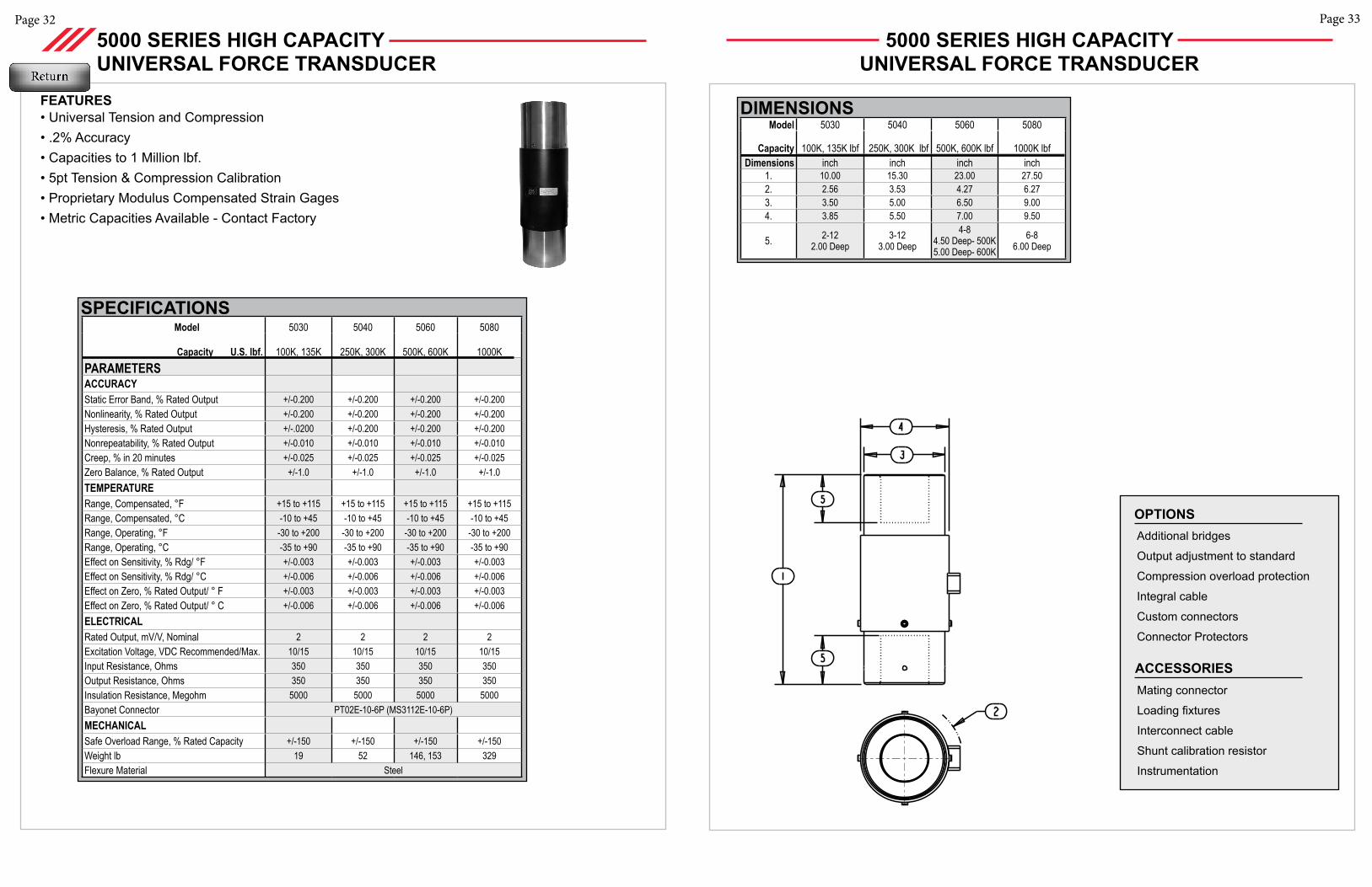
Model 5030 5040 5060 5080
Capacity U.S. lbf. 100K, 135K 250K, 300K 500K, 600K 1000KPARAMETERS ACCURACY Static Error Band, % Rated Output +/-0.200 +/-0.200 +/-0.200 +/-0.200Nonlinearity, % Rated Output +/-0.200 +/-0.200 +/-0.200 +/-0.200Hysteresis, % Rated Output +/-.0200 +/-0.200 +/-0.200 +/-0.200Nonrepeatability, % Rated Output +/-0.010 +/-0.010 +/-0.010 +/-0.010Creep, % in 20 minutes +/-0.025 +/-0.025 +/-0.025 +/-0.025Zero Balance, % Rated Output +/-1.0 +/-1.0 +/-1.0 +/-1.0TEMPERATURERange, Compensated, °F +15 to +115 +15 to +115 +15 to +115 +15 to +115Range, Compensated, °C -10 to +45 -10 to +45 -10 to +45 -10 to +45Range, Operating, °F -30 to +200 -30 to +200 -30 to +200 -30 to +200Range, Operating, °C -35 to +90 -35 to +90 -35 to +90 -35 to +90Effect on Sensitivity, % Rdg/ °F +/-0.003 +/-0.003 +/-0.003 +/-0.003Effect on Sensitivity, % Rdg/ °C +/-0.006 +/-0.006 +/-0.006 +/-0.006Effect on Zero, % Rated Output/ ° F +/-0.003 +/-0.003 +/-0.003 +/-0.003Effect on Zero, % Rated Output/ ° C +/-0.006 +/-0.006 +/-0.006 +/-0.006ELECTRICALRated Output, mV/V, Nominal 2 2 2 2Excitation Voltage, VDC Recommended/Max. 10/15 10/15 10/15 10/15Input Resistance, Ohms 350 350 350 350Output Resistance, Ohms 350 350 350 350Insulation Resistance, Megohm 5000 5000 5000 5000Bayonet Connector PT02E-10-6P (MS3112E-10-6P)MECHANICALSafe Overload Range, % Rated Capacity +/-150 +/-150 +/-150 +/-150Weight lb 19 52 146, 153 329Flexure Material Steel
FEATURES• Universal Tension and Compression• .2% Accuracy• Capacities to 1 Million lbf. • 5pt Tension & Compression Calibration• Proprietary Modulus Compensated Strain Gages • Metric Capacities Available - Contact Factory
5000 SERIES HIGH CAPACITY UNIVERSAL FORCE TRANSDUCER
SPECIFICATIONS
5000 SERIES HIGH CAPACITY UNIVERSAL FORCE TRANSDUCER
Model 5030 5040 5060 5080
Capacity 100K, 135K lbf 250K, 300K lbf 500K, 600K lbf 1000K lbfDimensions inch inch inch inch
1. 10.00 15.30 23.00 27.502. 2.56 3.53 4.27 6.273. 3.50 5.00 6.50 9.004. 3.85 5.50 7.00 9.50
5. 2-122.00 Deep
3-123.00 Deep
4-84.50 Deep- 500K5.00 Deep- 600K
6-86.00 Deep
DIMENSIONS
Page 35Page 34
SPECIFICATIONS
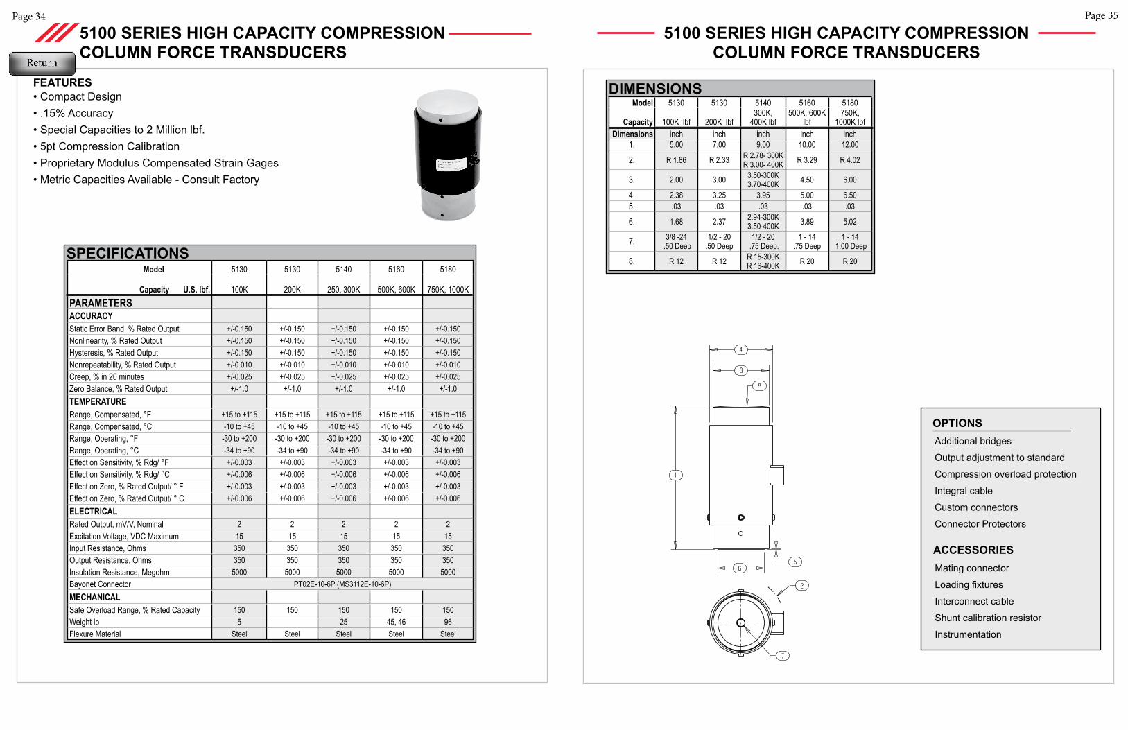
FEATURES• Compact Design• .15% Accuracy• Special Capacities to 2 Million lbf.• 5pt Compression Calibration• Proprietary Modulus Compensated Strain Gages • Metric Capacities Available - Consult Factory
5100 SERIES HIGH CAPACITY COMPRESSION COLUMN FORCE TRANSDUCERS
Model 5130 5130 5140 5160 5180
Capacity U.S. lbf. 100K 200K 250, 300K 500K, 600K 750K, 1000KPARAMETERS ACCURACY Static Error Band, % Rated Output +/-0.150 +/-0.150 +/-0.150 +/-0.150 +/-0.150Nonlinearity, % Rated Output +/-0.150 +/-0.150 +/-0.150 +/-0.150 +/-0.150Hysteresis, % Rated Output +/-0.150 +/-0.150 +/-0.150 +/-0.150 +/-0.150Nonrepeatability, % Rated Output +/-0.010 +/-0.010 +/-0.010 +/-0.010 +/-0.010Creep, % in 20 minutes +/-0.025 +/-0.025 +/-0.025 +/-0.025 +/-0.025Zero Balance, % Rated Output +/-1.0 +/-1.0 +/-1.0 +/-1.0 +/-1.0TEMPERATURERange, Compensated, °F +15 to +115 +15 to +115 +15 to +115 +15 to +115 +15 to +115Range, Compensated, °C -10 to +45 -10 to +45 -10 to +45 -10 to +45 -10 to +45Range, Operating, °F -30 to +200 -30 to +200 -30 to +200 -30 to +200 -30 to +200Range, Operating, °C -34 to +90 -34 to +90 -34 to +90 -34 to +90 -34 to +90Effect on Sensitivity, % Rdg/ °F +/-0.003 +/-0.003 +/-0.003 +/-0.003 +/-0.003Effect on Sensitivity, % Rdg/ °C +/-0.006 +/-0.006 +/-0.006 +/-0.006 +/-0.006Effect on Zero, % Rated Output/ ° F +/-0.003 +/-0.003 +/-0.003 +/-0.003 +/-0.003Effect on Zero, % Rated Output/ ° C +/-0.006 +/-0.006 +/-0.006 +/-0.006 +/-0.006ELECTRICALRated Output, mV/V, Nominal 2 2 2 2 2Excitation Voltage, VDC Maximum 15 15 15 15 15Input Resistance, Ohms 350 350 350 350 350Output Resistance, Ohms 350 350 350 350 350Insulation Resistance, Megohm 5000 5000 5000 5000 5000Bayonet Connector PT02E-10-6P (MS3112E-10-6P)MECHANICALSafe Overload Range, % Rated Capacity 150 150 150 150 150Weight lb 5 25 45, 46 96Flexure Material Steel Steel Steel Steel Steel
Additional bridges
Output adjustment to standard
Compression overload protection
Integral cable
Custom connectors
Connector Protectors
OPTIONS
Mating connector
Loading fixtures
Interconnect cable
Shunt calibration resistor
Instrumentation
ACCESSORIES
5100 SERIES HIGH CAPACITY COMPRESSION COLUMN FORCE TRANSDUCERS
Model 5130 5130 5140 5160 5180
Capacity 100K lbf 200K lbf300K,
400K lbf500K, 600K
lbf750K,
1000K lbfDimensions inch inch inch inch inch
1. 5.00 7.00 9.00 10.00 12.00
2. R 1.86 R 2.33 R 2.78- 300KR 3.00- 400K R 3.29 R 4.02
3. 2.00 3.00 3.50-300K3.70-400K 4.50 6.00
4. 2.38 3.25 3.95 5.00 6.505. .03 .03 .03 .03 .03
6. 1.68 2.37 2.94-300K3.50-400K 3.89 5.02
7. 3/8 -24 .50 Deep
1/2 - 20 .50 Deep
1/2 - 20 .75 Deep.
1 - 14.75 Deep
1 - 14 1.00 Deep
8. R 12 R 12 R 15-300KR 16-400K R 20 R 20
DIMENSIONS
Page 37Page 36
Additional bridges
Output adjustment to standard
Compression overload protection
Integral cable
Custom connectors
Connector Protectors
OPTIONS
Mating connector
Loading fixtures
Interconnect cable
Shunt calibration resistor
Instrumentation
ACCESSORIES
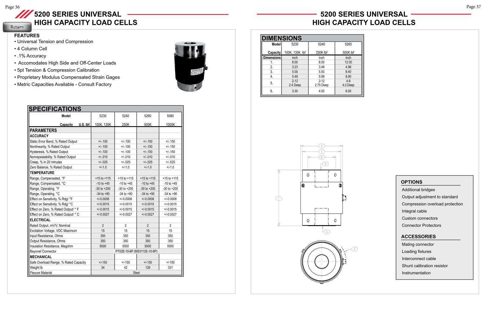
Model 5230 5240 5260 5080
Capacity U.S. lbf. 100K, 135K 250K 500K 1000KPARAMETERS ACCURACY Static Error Band, % Rated Output +/-.100 +/-.100 +/-.100 +/-.150Nonlinearity, % Rated Output +/-.100 +/-.100 +/-.100 +/-.150Hysteresis, % Rated Output +/-.100 +/-.100 +/-.100 +/-.150Nonrepeatability, % Rated Output +/-.010 +/-.010 +/-.010 +/-.010Creep, % in 20 minutes +/-.025 +/-.025 +/-.025 +/-.025Zero Balance, % Rated Output +/-1.0 +/-1.0 +/-1.0 +/-1.0TEMPERATURERange, Compensated, °F +15 to +115 +15 to +115 +15 to +115 +15 to +115Range, Compensated, °C -10 to +45 -10 to +45 -10 to +45 -10 to +45Range, Operating, °F -30 to +200 -30 to +200 -30 to +200 -30 to +200Range, Operating, °C -34 to +90 -34 to +90 -34 to +90 -34 to +90Effect on Sensitivity, % Rdg/ °F +/-0.0008 +/-0.0008 +/-0.0008 +/-0.0008Effect on Sensitivity, % Rdg/ °C +/-0.0015 +/-0.0015 +/-0.0015 +/-0.0015Effect on Zero, % Rated Output/ ° F +/-0.0015 +/-0.0015 +/-0.0015 +/-0.0015Effect on Zero, % Rated Output/ ° C +/-0.0027 +/-0.0027 +/-0.0027 +/-0.0027ELECTRICALRated Output, mV/V, Nominal 2 2 2 2Excitation Voltage, VDC Maximum 15 15 15 15Input Resistance, Ohms 350 350 350 350Output Resistance, Ohms 350 350 350 350Insulation Resistance, Megohm 5000 5000 5000 5000Bayonet Connector PT02E-10-6P (MS3112E-10-6P)MECHANICALSafe Overload Range, % Rated Capacity +/-150 +/-150 +/-150 +/-150Weight lb 34 42 129 331Flexure Material Steel
FEATURES• Universal Tension and Compression• 4 Column Cell• .1% Accuracy• Accomodates High Side and Off-Center Loads• 5pt Tension & Compression Calibration• Proprietary Modulus Compensated Strain Gages • Metric Capacities Available - Consult Factory
5200 SERIES UNIVERSAL HIGH CAPACITY LOAD CELLS
SPECIFICATIONS
5200 SERIES UNIVERSAL HIGH CAPACITY LOAD CELLS
Model 5230 5240 5260
Capacity 100K, 135K lbf 250K lbf 500K lbfDimensions inch inch inch
1. 8.00 8.00 12.002. 3.23 3.48 4.963. 5.00 5.50 8.404. 5.49 5.99 8.90
5. 2-122.4 Deep
2-122.75 Deep
4-84.0 Deep
6. 3.30 4.00 6.00
DIMENSIONS
Page 39
Page 38
FEATURES
Model SWS10 SWS20 SWS30
Capacity U.S. lbf. 5K, 10K 25K, 50K 100KPARAMETERS Metric kN 25, 50 100, 250 500ACCURACY Static Error Band, % Rated Output +/-0.050 +/-0.050 +/-0.060Nonlinearity, % Rated Output +/-0.050 +/-0.050 +/-0.050Hysteresis, % Rated Output +/-0.060 +/-0.060 +/-0.060Nonrepeatability, % Rated Output +/-0.010 +/-0.010 +/-0.010Creep, % in 20 minutes +/-0.025 +/-0.025 +/-0.025Off-Center Load Sensitivity, %/inch +/-0.250 +/-0.250 +/-0.250Side Load Sensitivity, % +/-0.250 +/-0.250 +/-0.250Zero Balance, % Rated Output +/-1.0 +/-1.0 +/-1.0TEMPERATURERange, Compensated, °F +15 to +115 +15 to +115 +15 to +115Range, Compensated, °C -10 to +45 -10 to +45 -10 to +45Range, Operating, °F -65 to +200 -65 to +200 -65 to +200Range, Operating, °C -55 to +90 -55 to +90 -55 to +90Effect on Sensitivity, % Rdg/ °F +/-0.0008 +/-0.0008 +/-0.0008Effect on Sensitivity, % Rdg/ °C +/-0.0015 +/-0.0015 +/-0.0015Effect on Zero, % Rated Output/ °F +/-0.0015 +/-0.0015 +/-0.0015Effect on Zero, % Rated Output/ °C +/-0.0027 +/-0.0027 +/-0.0027ELECTRICALRated Output, mV/V, Nominal 4 4 4Excitation Voltage, VDC Maximum 20 20 20Input Resistance, Ohms 350 + 40/-3.5 350 + 40/-3.5 350 + 40/-3.5 Output Resistance, Ohms 350 +/-3.5 350 +/-3.5 350 +/-3.5Insulation Resistance, Megohm 5000 @ 50 VDC 5000 @ 50 VDC 5000 @ 50 VDCBayonet Connector PT02E-10-6P (MS3112E-10-6P)MECHANICALSafe Overload Range, % Rated Capacity +/-150 +/-150 +/-150Weight lb 2.9 9.1 23.5Weight kg 1.3 4.1 10.7Weight w/base lb 6.5 21.5 52.5Weight w/base kg 3.0 9.8 23.8Flexure Material Stainless Steel
STAINLESS STEEL (SWS)SERIES FORCE TRANSDUCERS
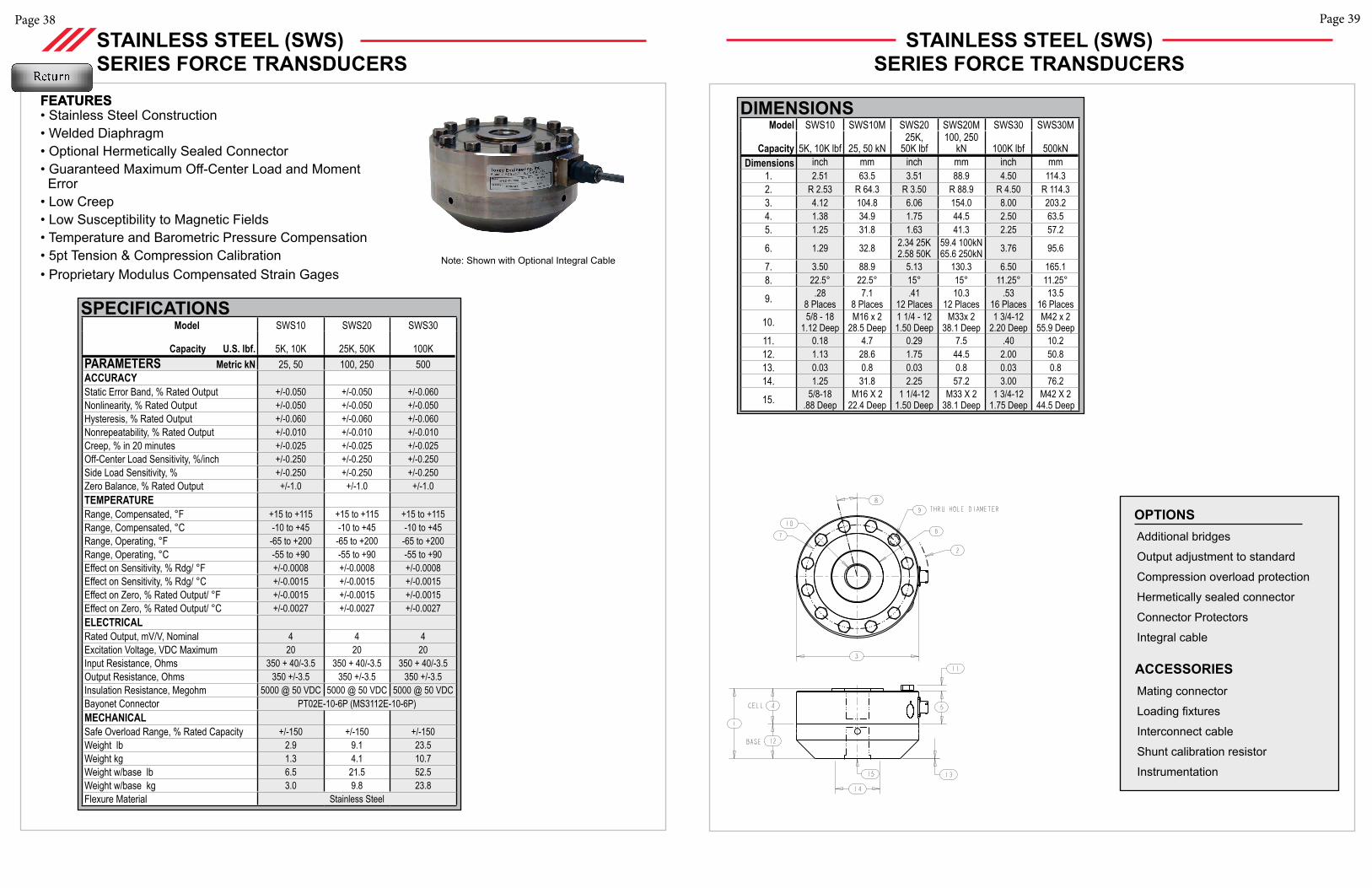
FEATURES• Stainless Steel Construction• Welded Diaphragm• Optional Hermetically Sealed Connector• Guaranteed Maximum Off-Center Load and Moment Error • Low Creep• Low Susceptibility to Magnetic Fields• Temperature and Barometric Pressure Compensation• 5pt Tension & Compression Calibration• Proprietary Modulus Compensated Strain Gages
Note: Shown with Optional Integral Cable
SPECIFICATIONS
Additional bridges
Output adjustment to standard
Compression overload protection
Hermetically sealed connector
Connector Protectors
Integral cable
OPTIONS
Mating connector
Loading fixtures
Interconnect cable
Shunt calibration resistor
Instrumentation
ACCESSORIES
STAINLESS STEEL (SWS)SERIES FORCE TRANSDUCERS
Model SWS10 SWS10M SWS20 SWS20M SWS30 SWS30M
Capacity 5K, 10K lbf 25, 50 kN25K,
50K lbf100, 250
kN 100K lbf 500kNDimensions inch mm inch mm inch mm
1. 2.51 63.5 3.51 88.9 4.50 114.32. R 2.53 R 64.3 R 3.50 R 88.9 R 4.50 R 114.33. 4.12 104.8 6.06 154.0 8.00 203.24. 1.38 34.9 1.75 44.5 2.50 63.55. 1.25 31.8 1.63 41.3 2.25 57.2
6. 1.29 32.8 2.34 25K2.58 50K
59.4 100kN65.6 250kN 3.76 95.6
7. 3.50 88.9 5.13 130.3 6.50 165.18. 22.5° 22.5° 15° 15° 11.25° 11.25°
9. .288 Places
7.18 Places
.4112 Places
10.312 Places
.5316 Places
13.516 Places
10. 5/8 - 181.12 Deep
M16 x 228.5 Deep
1 1/4 - 121.50 Deep
M33x 238.1 Deep
1 3/4-12 2.20 Deep
M42 x 255.9 Deep
11. 0.18 4.7 0.29 7.5 .40 10.212. 1.13 28.6 1.75 44.5 2.00 50.813. 0.03 0.8 0.03 0.8 0.03 0.814. 1.25 31.8 2.25 57.2 3.00 76.2
15. 5/8-18.88 Deep
M16 X 222.4 Deep
1 1/4-121.50 Deep
M33 X 2 38.1 Deep
1 3/4-121.75 Deep
M42 X 244.5 Deep
DIMENSIONS
Page 41Page 40
FEATURES
Model FRS10 FRS20
Capacity U.S. lbf. 2.5K, 5K 12.5K, 25KPARAMETERS Metric kN 12.5, 25 50, 125ACCURACY Static Error Band, % Rated Output +/-0.050 +/-0.050Nonlinearity, % Rated Output +/-0.050 +/-0.050Hysteresis, % Rated Output +/-0.060 +/-0.060Nonrepeatability, % Rated Output +/-0.010 +/-0.010Creep, % in 20 minutes +/-0.025 +/-0.025Off-Center Load Sensitivity, %/inch +/-0.250 +/-0.250Side Load Sensitivity, % +/-0.250 +/-0.250Zero Balance, % Rated Output +/-1.0 +/-1.0TEMPERATURERange, Compensated, °F +15 to +115 +15 to +115Range, Compensated, °C -10 to +45 -10 to +45Range, Operating, °F -65 to +200 -65 to +200Range, Operating, °C -55 to +90 -55 to +90Effect on Sensitivity, % Rdg/ °F +/-0.0008 +/-0.0008Effect on Sensitivity, % Rdg/ °C +/-0.0015 +/-0.0015Effect on Zero, % Rated Output/ ° F +/-0.0015 +/-0.0015Effect on Zero, % Rated Output/ ° C +/-0.0027 +/-0.0027ELECTRICALRated Output, mV/V, Nominal 2 2Excitation Voltage, VDC Maximum 20 20Input Resistance, Ohms 350 + 40/-3.5 350 + 40/-3.5 Output Resistance, Ohms 350 +/-3.5 350 +/-3.5
Insulation Resistance, Megohm 5000 @ 50 VDC 5000 @ 50 VDC
Bayonet Connector PT02E-10-6P (MS3112E-10-6P)MECHANICALSafe Overload Range, % Rated Capacity +/-300 +/-300Weight lb 2.9 9.1Weight kg 1.3 4.1Weight w/base lb 6.5 21.5Weight w/base kg 3.0 9.8 Flexure Material Stainless Steel
SPECIFICATIONS
FATIGUE RATED STAINLESS STEEL (FRS) SERIES FORCE TRANSDUCERS
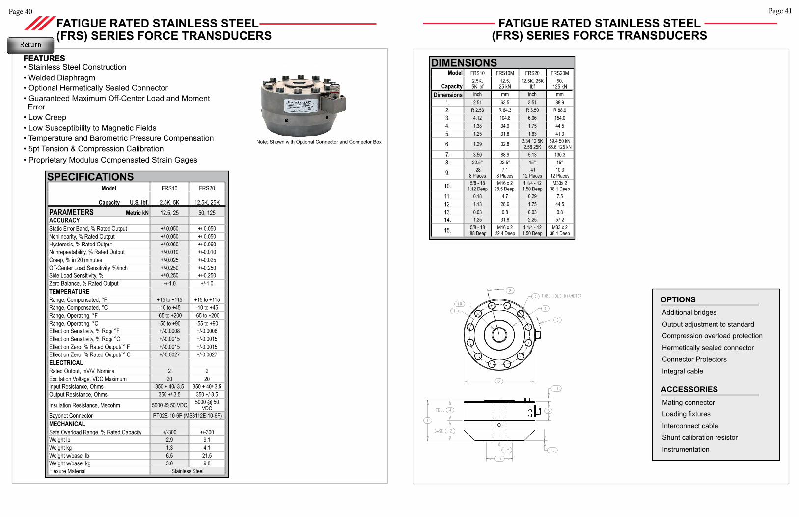
FEATURES• Stainless Steel Construction• Welded Diaphragm• Optional Hermetically Sealed Connector• Guaranteed Maximum Off-Center Load and Moment Error• Low Creep• Low Susceptibility to Magnetic Fields• Temperature and Barometric Pressure Compensation• 5pt Tension & Compression Calibration• Proprietary Modulus Compensated Strain Gages
Note: Shown with Optional Connector and Connector Box
Additional bridges
Output adjustment to standard
Compression overload protection
Hermetically sealed connector
Connector Protectors
Integral cable
OPTIONS
Mating connector
Loading fixtures
Interconnect cable
Shunt calibration resistor
Instrumentation
ACCESSORIES
Model FRS10 FRS10M FRS20 FRS20M
Capacity2.5K, 5K lbf
12.5, 25 kN
12.5K, 25K lbf
50, 125 kN
Dimensions inch mm inch mm1. 2.51 63.5 3.51 88.92. R 2.53 R 64.3 R 3.50 R 88.93. 4.12 104.8 6.06 154.04. 1.38 34.9 1.75 44.55. 1.25 31.8 1.63 41.3
6. 1.29 32.8 2.34 12.5K2.58 25K
59.4 50 kN 65.6 125 kN
7. 3.50 88.9 5.13 130.38. 22.5° 22.5° 15° 15°
9. .288 Places
7.18 Places
.4112 Places
10.312 Places
10. 5/8 - 181.12 Deep
M16 x 228.5 Deep.
1 1/4 - 121.50 Deep
M33x 238.1 Deep
11. 0.18 4.7 0.29 7.512. 1.13 28.6 1.75 44.513. 0.03 0.8 0.03 0.814. 1.25 31.8 2.25 57.2
15. 5/8 - 18 .88 Deep
M16 x 222.4 Deep
1 1/4 - 12 1.50 Deep
M33 x 238.1 Deep
FATIGUE RATED STAINLESS STEEL (FRS) SERIES FORCE TRANSDUCERS
DIMENSIONS
Page 43Page 42
DIMENSIONSModel 2029 2030
Capacity500, 1000,
5K lbf2.5K, 5K, 7.5K lbf
Dimensions inch inch1. 3.50 3.502. 1.70 1.703. 1.57 1.574. 5/8-18 3/4-165. .75 .75
Model 2029 2030
Capacity U.S. lbf. 500, 1000, 5K 2.5K, 5K, 7.5KPARAMETERS ACCURACY Static Error Band, % Rated Output +/-0.250 +/-0.250Nonlinearity, % Rated Output +/-0.250 +/-0.250Hysteresis, % Rated Output +/-0.150 +/-0.150Nonrepeatability, % Rated Output +/-0.050 +/-0.050Creep, % in 20 minutes +/-0.030 +/-0.030Zero Balance, % Rated Output +/-1.0 +/-1.0TEMPERATURERange, Compensated, °F +15 to +115 +15 to +115Range, Compensated, °C -10 to +45 -10 to +45Range, Operating, °F -65 to +200 -65 to +200Range, Operating, °C -55 to +90 -55 to +90Effect on Sensitivity, % Rdg/ °F +/-0.0015 +/-0.0015Effect on Sensitivity, % Rdg/ °C +/-0.0027 +/-0.0027Effect on Zero, % Rated Output/ °F +/-0.0015 +/-0.0015Effect on Zero, % Rated Output/ °C +/-0.0027 +/-0.0027ELECTRICALRated Output, mV/V, Nominal 1 1Excitation Voltage, VDC Maximum 15 15Input Resistance, Ohms 1000 +100/-10 1000 +100/-10Output Resistance, Ohms 1000 +100/-10 1000 +100/-10Insulation Resistance, Megohm 5000 (@ 50VDC) MECHANICALSafe Overload Range, % Rated Capacity +/-150 +/-150Weight lbFlexure Material Stainless Steel Stainless Steel
SPECIFICATIONS
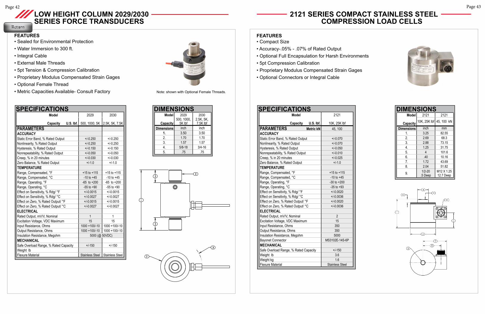
FEATURES• Sealed for Environmental Protection• Water Immersion to 300 ft.• Integral Cable• External Male Threads• 5pt Tension & Compression Calibration• Proprietary Modulus Compensated Strain Gages• Optional Female Thread • Metric Capacities Available- Consult Factory
LOW HEIGHT COLUMN 2029/2030 SERIES FORCE TRANSDUCERS
Note: shown with Optional Female Threads.
2121 SERIES COMPACT STAINLESS STEEL COMPRESSION LOAD CELLS
FEATURES• Compact Size• Accuracy-.05% - .07% of Rated Output• Optional Full Encapsulation for Harsh Environments• 5pt Compression Calibration• Proprietary Modulus Compensated Strain Gages• Optional Connectors or Integral Cable
Model 2121
Capacity U.S. lbf. 10K, 25K lbfPARAMETERS Metric kN 45, 100ACCURACY Static Error Band, % Rated Output +/-0.070Nonlinearity, % Rated Output +/-0.070Hysteresis, % Rated Output +/-0.050Nonrepeatability, % Rated Output +/-0.010Creep, % in 20 minutes +/-0.025Zero Balance, % Rated Output +/-1.0TEMPERATURERange, Compensated, °F +15 to +115Range, Compensated, °C -10 to +45Range, Operating, °F -30 to +200Range, Operating, °C -35 to +93Effect on Sensitivity, % Rdg/ °F +/-0.0020Effect on Sensitivity, % Rdg/ °C +/-0.0036Effect on Zero, % Rated Output/ °F +/-0.0020Effect on Zero, % Rated Output/ °C +/-0.0036ELECTRICALRated Output, mV/V, Nominal 2Excitation Voltage, VDC Maximum 15Input Resistance, Ohms 350 Output Resistance, Ohms 350Insulation Resistance, Megohm 5000 Bayonet Connector MS3102E-14S-6PMECHANICALSafe Overload Range, % Rated Capacity +/-150Weight lb 3.6Weight kg 1.6Flexure Material Stainless Steel
SPECIFICATIONS DIMENSIONSModel 2121 2121
Capacity 10K, 25K lbf 45, 100 kN
Dimensions inch mm1. 3.25 82.552. 2.69 68.33. 2.88 73.154. 1.25 31.755. 4 101.66. .40 10.167. 1.72 43.698. 2.04 51.82
9. 1/2-20.5 Deep
M12 X 1.2512.7 Deep
Page 45
MODEL 4110 STAINLESS STEEL FORCE TRANSDUCERS
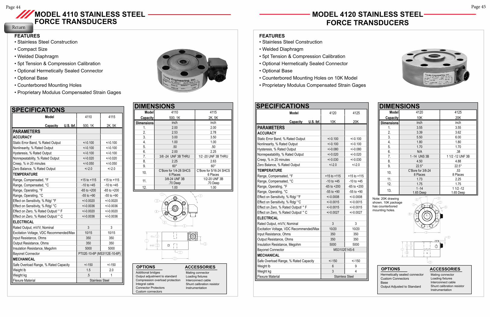
FEATURES• Stainless Steel Construction• Compact Size• Welded Diaphragm• 5pt Tension & Compression Calibration• Optional Hermetically Sealed Connector• Optional Base• Counterbored Mounting Holes• Proprietary Modulus Compensated Strain Gages
Model 4110 4115
Capacity U.S. lbf. 500, 1K 2K, 5KPARAMETERS ACCURACY Static Error Band, % Rated Output +/-0.100 +/-0.100Nonlinearity, % Rated Output +/-0.100 +/-0.100Hysteresis, % Rated Output +/-0.100 +/-0.100Nonrepeatability, % Rated Output +/-0.020 +/-0.020Creep, % in 20 minutes +/-0.050 +/-0.050Zero Balance, % Rated Output +/-2.0 +/-2.0TEMPERATURERange, Compensated, °F +15 to +115 +15 to +115Range, Compensated, °C -10 to +45 -10 to +45Range, Operating, °F -65 to +200 -65 to +200Range, Operating, °C -55 to +90 -55 to +90Effect on Sensitivity, % Rdg/ °F +/-0.0020 +/-0.0020Effect on Sensitivity, % Rdg/ °C +/-0.0036 +/-0.0036Effect on Zero, % Rated Output/ ° F +/-0.0020 +/-0.0020Effect on Zero, % Rated Output/ ° C +/-0.0036 +/-0.0036ELECTRICALRated Output, mV/V, Nominal 3 3Excitation Voltage, VDC Recommended/Max 10/15 10/15Input Resistance, Ohms 350 350 Output Resistance, Ohms 350 350 Insulation Resistance, Megohm 5000 5000 Bayonet Connector PT02E-10-6P (MS3112E-10-6P)MECHANICALSafe Overload Range, % Rated Capacity +/-150 +/-150Weight lb 1.5 2.0Weight kg .5 1Flexure Material Stainless Steel
SPECIFICATIONS Model 4110 4115Capacity 500, 1K 2K, 5K
Dimensions inch inch1. 2.00 2.002. 2.53 2.783. 3.00 3.504. 1.00 1.005. .50 .506. 2.00 2.257. 3/8 -24 UNF 3B THRU 1/2 -20 UNF 3B THRU8. 2.25 2.639. 60° 60°
10. C’Bore for 1/4-28 SHCS6 Places
C’Bore for 5/16-24 SHCS6 Places
11. 3/8-24 UNF 3B.70 Deep
1/2-20 UNF 3B.70 Deep
12. 1.00 1.00
DIMENSIONS
Additional bridgesOutput adjustment to standardCompression overload protectionIntegral cableConnector ProtectorsCustom connectors
OPTIONS Mating connectorLoading fixturesInterconnect cableShunt calibration resistorInstrumentation
ACCESSORIES
Page 44
MODEL 4120 STAINLESS STEEL FORCE TRANSDUCERS
FEATURES• Stainless Steel Construction• Welded Diaphragm• 5pt Tension & Compression Calibration• Optional Hermetically Sealed Connector• Optional Base• Counterbored Mounting Holes on 10K Model• Proprietary Modulus Compensated Strain Gages
Model 4120 4125
Capacity U.S. lbf. 10K 20KPARAMETERS ACCURACY Static Error Band, % Rated Output +/-0.100 +/-0.100Nonlinearity, % Rated Output +/-0.100 +/-0.100Hysteresis, % Rated Output +/-0.080 +/-0.080Nonrepeatability, % Rated Output +/-0.020 +/-0.020Creep, % in 20 minutes +/-0.030 +/-0.030Zero Balance, % Rated Output +/-2.0 +/-2.0TEMPERATURERange, Compensated, °F +15 to +115 +15 to +115Range, Compensated, °C -10 to +45 -10 to +45Range, Operating, °F -65 to +200 -65 to +200Range, Operating, °C -55 to +90 -55 to +90Effect on Sensitivity, % Rdg/ °F +/-0.0008 +/-0.0008Effect on Sensitivity, % Rdg/ °C +/-0.0015 +/-0.0015Effect on Zero, % Rated Output/ ° F +/-0.0015 +/-0.0015Effect on Zero, % Rated Output/ ° C +/-0.0027 +/-0.0027ELECTRICALRated Output, mV/V, Nominal 3 3Excitation Voltage, VDC Recommended/Max 10/20 10/20Input Resistance, Ohms 350 350 Output Resistance, Ohms 350 350 Insulation Resistance, Megohm 5000 5000 Bayonet Connector MS3102E14S-6MECHANICALSafe Overload Range, % Rated Capacity +/-150 +/-150Weight lb 6 9Weight kg 3 4Flexure Material Stainless Steel
SPECIFICATIONSModel 4120 4125
Capacity 10K 20KDimensions inch inch
1. 3.55 3.552. 3.39 3.623. 5.50 6.004. 1.80 1.805. 1.70 1.706. N/A .387. 1 -14 UNS 3B 1 1/2 -12 UNF 3B8. 4.50 4.889. 22.5° 22.5°
10. C’Bore for 3/8-248 Places
.538 Places
11. 1.73 2.2512. 1.75 1.75
13. 1 -141.65 Deep
1 1/2 -12 1.65 Deep
DIMENSIONS
Hermetically sealed connectorCustom ConnectorsBaseOutput Adjusted to Standard
OPTIONS Mating connectorLoading fixturesInterconnect cableShunt calibration resistorInstrumentation
ACCESSORIES
Note: 20K drawing shown. 10K package has counterbored mounting holes.
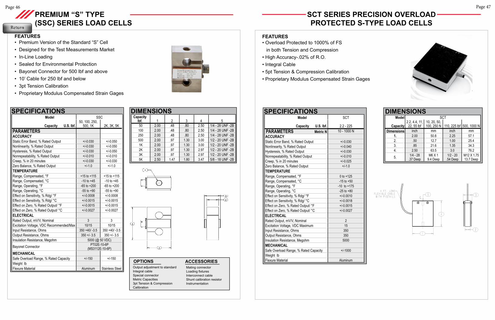
Page 47
Page 46
DIMENSIONSCapacity
lbf. 1 2 3 4 550 2.00 .48 .80 2.50 1/4 - 28 UNF -2B100 2.00 .48 .80 2.50 1/4 - 28 UNF -2B250 2.00 .48 .80 2.50 1/4 - 28 UNF -2B500 2.00 .97 1.30 3.00 1/2 - 20 UNF -2B1K 2.00 .97 1.30 3.00 1/2 - 20 UNF -2B2K 2.00 .97 1.30 2.97 1/2 - 20 UNF -2B3K 2.00 .97 1.30 2.97 1/2 - 20 UNF -2B5K 2.50 1.47 1.80 3.47 5/8 - 18 UNF -2B
PREMIUM “S” TYPE (SSC) SERIES LOAD CELLS
FEATURES• Premium Version of the Standard “S” Cell• Designed for the Test Measurements Market• In-Line Loading• Sealed for Environmental Protection• Bayonet Connector for 500 lbf and above• 10’ Cable for 250 lbf and below • 3pt Tension Calibration• Proprietary Modulus Compensated Strain Gages
Model SSC
Capacity U.S. lbf.50, 100, 250,
500, 1K 2K, 3K, 5KPARAMETERS ACCURACY Static Error Band, % Rated Output +/-0.030 +/-0.050Nonlinearity, % Rated Output +/-0.030 +/-0.050Hysteresis, % Rated Output +/-0.030 +/-0.050Nonrepeatability, % Rated Output +/-0.010 +/-0.010Creep, % in 20 minutes +/-0.030 +/-0.030Zero Balance, % Rated Output +/-1.0 +/-1.0TEMPERATURERange, Compensated, °F +15 to +115 +15 to +115Range, Compensated, °C -10 to +45 -10 to +45Range, Operating, °F -65 to +200 -65 to +200Range, Operating, °C -55 to +90 -55 to +90Effect on Sensitivity, % Rdg/ °F +/-0.0008 +/-0.0008Effect on Sensitivity, % Rdg/ °C +/-0.0015 +/-0.0015Effect on Zero, % Rated Output/ °F +/-0.0015 +/-0.0015Effect on Zero, % Rated Output/ °C +/-0.0027 +/-0.0027ELECTRICALRated Output, mV/V, Nominal 3 3Excitation Voltage, VDC Recommended/Max 10/15 10/15Input Resistance, Ohms 350 +40/ -3.5 350 +40/ -3.5Output Resistance, Ohms 350 +/- 3.5 350 +/- 3.5Insulation Resistance, Megohm 5000 (@ 50 VDC)
Bayonet Connector PT02E-10-6P (MS3112E-10-6P)
MECHANICALSafe Overload Range, % Rated Capacity +/-150 +/-150Weight lbFlexure Material Aluminum Stainless Steel
SPECIFICATIONS
Output adjustment to standard Integral cableSpecial connectorMetric Capacities3pt Tension & Compression Calibration
OPTIONS Mating connectorLoading fixturesInterconnect cableShunt calibration resistorInstrumentation
ACCESSORIES
SCT SERIES PRECISION OVERLOAD PROTECTED S-TYPE LOAD CELLS
DIMENSIONSModel SCT
Capacity2.2, 4.4, 11, 22, 55 lbf
10, 20, 50, 100, 250 N 110, 225 lbf 500, 1000 N
Dimensions inch mm inch mm 1. 2.00 50.8 2.25 57.12. .50 12.7 1.00 25.43. .85 21.6 1.35 34.34. 2.50 63.5 3.0 76.2
5. 1/4 - 28.37 Deep
M6 X 19.4 Deep
1/2 - 20.54 Deep
M12 X 1.7513.7 Deep
Model SCT
Capacity U.S. lbf. 2.2 - 225 PARAMETERS Metric N 10 - 1000 N ACCURACY Static Error Band, % Rated Output +/-0.030Nonlinearity, % Rated Output +/-0.040Hysteresis, % Rated Output +/-0.030Nonrepeatability, % Rated Output +/-0.010Creep, % in 20 minutes +/-0.025Zero Balance, % Rated Output +/-1.0TEMPERATURERange, Compensated, °F 0 to +125Range, Compensated, °C -15 to +50Range, Operating, °F -10 to +175Range, Operating, °C -25 to +80Effect on Sensitivity, % Rdg/ °F +/-0.0010Effect on Sensitivity, % Rdg/ °C +/-0.0018Effect on Zero, % Rated Output/ °F +/-0.0015Effect on Zero, % Rated Output/ °C +/-0.0027ELECTRICALRated Output, mV/V, Nominal 2Excitation Voltage, VDC Maximum 15Input Resistance, Ohms 350Output Resistance, Ohms 350Insulation Resistance, Megohm 5000MECHANICALSafe Overload Range, % Rated Capacity +/-1000Weight lbFlexure Material Aluminum
SPECIFICATIONS
FEATURES• Overload Protected to 1000% of FS in both Tension and Compression• High Accuracy-.02% of R.O.• Integral Cable• 5pt Tension & Compression Calibration• Proprietary Modulus Compensated Strain Gages
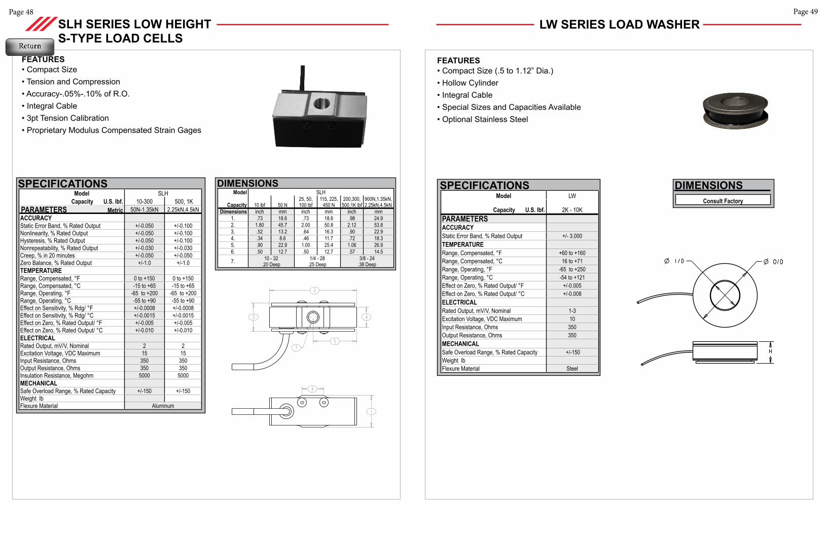
Page 48
SLH SERIES LOW HEIGHT S-TYPE LOAD CELLS
FEATURES• Compact Size • Tension and Compression• Accuracy-.05%-.10% of R.O.• Integral Cable• 3pt Tension Calibration• Proprietary Modulus Compensated Strain Gages
Model SLHCapacity U.S. lbf. 10-300 500, 1K
PARAMETERS Metric 50N-1.35kN 2.25kN,4.5kNACCURACY Static Error Band, % Rated Output +/-0.050 +/-0.100Nonlinearity, % Rated Output +/-0.050 +/-0.100Hysteresis, % Rated Output +/-0.050 +/-0.100Nonrepeatability, % Rated Output +/-0.030 +/-0.030Creep, % in 20 minutes +/-0.050 +/-0.050Zero Balance, % Rated Output +/-1.0 +/-1.0TEMPERATURERange, Compensated, °F 0 to +150 0 to +150Range, Compensated, °C -15 to +65 -15 to +65Range, Operating, °F -65 to +200 -65 to +200Range, Operating, °C -55 to +90 -55 to +90Effect on Sensitivity, % Rdg/ °F +/-0.0008 +/-0.0008Effect on Sensitivity, % Rdg/ °C +/-0.0015 +/-0.0015Effect on Zero, % Rated Output/ °F +/-0.005 +/-0.005Effect on Zero, % Rated Output/ °C +/-0.010 +/-0.010ELECTRICALRated Output, mV/V, Nominal 2 2Excitation Voltage, VDC Maximum 15 15Input Resistance, Ohms 350 350Output Resistance, Ohms 350 350Insulation Resistance, Megohm 5000 5000MECHANICALSafe Overload Range, % Rated Capacity +/-150 +/-150Weight lbFlexure Material Aluminum
SPECIFICATIONS DIMENSIONSModel SLH
Capacity 10 lbf 50 N25, 50,100 lbf
115, 225,450 N
200,300,500,1K lbf
900N,1.35kN,2.25kN,4.5kN
Dimensions inch mm inch mm inch mm 1. .73 18.6 .73 18.6 .98 24.92. 1.80 45.7 2.00 50.8 2.12 53.83. .52 13.2 .64 16.3 .90 22.94. .34 8.6 .46 11.7 .72 18.35. .90 22.9 1.00 25.4 1.06 26.96. .50 12.7 .50 12.7 .57 14.5
7. 10 - 32 .20 Deep
1/4 - 28 .25 Deep
3/8 - 24.38 Deep
Page 49
LW SERIES LOAD WASHER
FEATURES• Compact Size (.5 to 1.12” Dia.)• Hollow Cylinder • Integral Cable• Special Sizes and Capacities Available• Optional Stainless Steel
Model LW
Capacity U.S. lbf. 2K - 10KPARAMETERS ACCURACY Static Error Band, % Rated Output +/- 3.000TEMPERATURERange, Compensated, °F +60 to +160Range, Compensated, °C 16 to +71Range, Operating, °F -65 to +250Range, Operating, °C -54 to +121Effect on Zero, % Rated Output/ °F +/-0.005Effect on Zero, % Rated Output/ °C +/-0.008ELECTRICALRated Output, mV/V, Nominal 1-3Excitation Voltage, VDC Maximum 10Input Resistance, Ohms 350Output Resistance, Ohms 350MECHANICALSafe Overload Range, % Rated Capacity +/-150Weight lbFlexure Material Steel
SPECIFICATIONS DIMENSIONSConsult Factory
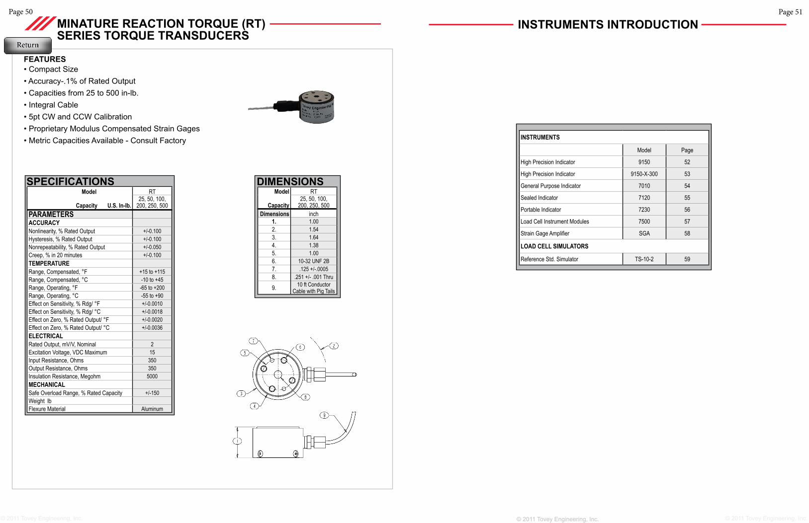
Page 50
© 2011 Tovey Engineering, Inc. © 2011 Tovey Engineering, Inc. © 2011 Tovey Engineering, Inc.
DIMENSIONSModel RT
Capacity25, 50, 100,
200, 250, 500 Dimensions inch
1. 1.002. 1.543. 1.644. 1.385. 1.006. 10-32 UNF 2B7. .125 +/-.00058. .251 +/- .001 Thru
9. 10 ft Conductor Cable with Pig Tails
Model RT
Capacity U.S. In-lb.25, 50, 100,
200, 250, 500 PARAMETERS ACCURACY Nonlinearity, % Rated Output +/-0.100Hysteresis, % Rated Output +/-0.100Nonrepeatability, % Rated Output +/-0.050Creep, % in 20 minutes +/-0.100TEMPERATURERange, Compensated, °F +15 to +115Range, Compensated, °C -10 to +45Range, Operating, °F -65 to +200Range, Operating, °C -55 to +90Effect on Sensitivity, % Rdg/ °F +/-0.0010Effect on Sensitivity, % Rdg/ °C +/-0.0018Effect on Zero, % Rated Output/ °F +/-0.0020Effect on Zero, % Rated Output/ °C +/-0.0036ELECTRICALRated Output, mV/V, Nominal 2Excitation Voltage, VDC Maximum 15Input Resistance, Ohms 350Output Resistance, Ohms 350Insulation Resistance, Megohm 5000 MECHANICALSafe Overload Range, % Rated Capacity +/-150Weight lbFlexure Material Aluminum
SPECIFICATIONS
FEATURES• Compact Size• Accuracy-.1% of Rated Output• Capacities from 25 to 500 in-lb.• Integral Cable• 5pt CW and CCW Calibration • Proprietary Modulus Compensated Strain Gages • Metric Capacities Available - Consult Factory
MINATURE REACTION TORQUE (RT) SERIES TORQUE TRANSDUCERS
Page 51
INSTRUMENTS INTRODUCTION
INSTRUMENTS
Model Page
High Precision Indicator 9150 52
High Precision Indicator 9150-X-300 53
General Purpose Indicator 7010 54
Sealed Indicator 7120 55
Portable Indicator 7230 56
Load Cell Instrument Modules 7500 57
Strain Gage Amplifier SGA 58
LOAD CELL SIMULATORS
Reference Std. Simulator TS-10-2 59
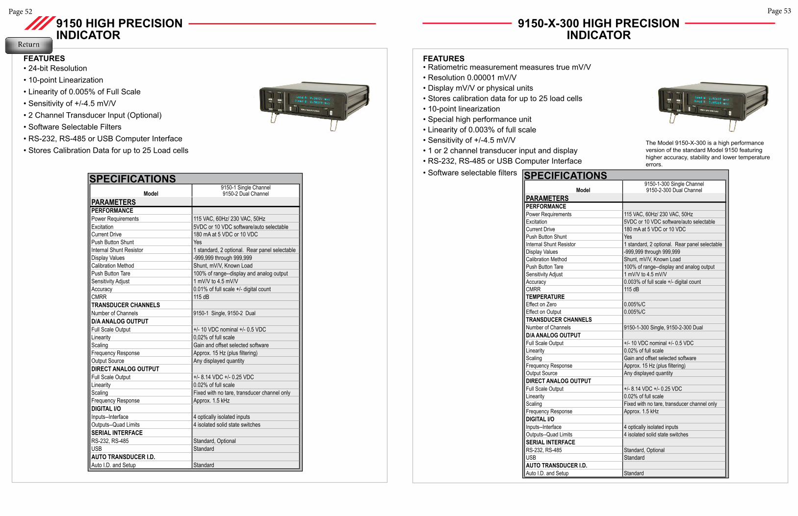
Page 53Page 52
Model9150-1 Single Channel9150-2 Dual Channel
PARAMETERS PERFORMANCE Power Requirements 115 VAC, 60Hz/ 230 VAC, 50HzExcitation 5VDC or 10 VDC software/auto selectableCurrent Drive 180 mA at 5 VDC or 10 VDCPush Button Shunt YesInternal Shunt Resistor 1 standard, 2 optional. Rear panel selectableDisplay Values -999,999 through 999,999Calibration Method Shunt, mV/V, Known LoadPush Button Tare 100% of range--display and analog outputSensitivity Adjust 1 mV/V to 4.5 mV/VAccuracy 0.01% of full scale +/- digital countCMRR 115 dBTRANSDUCER CHANNELSNumber of Channels 9150-1 Single, 9150-2 Dual D/A ANALOG OUTPUTFull Scale Output +/- 10 VDC nominal +/- 0.5 VDCLinearity 0,02% of full scaleScaling Gain and offset selected softwareFrequency Response Approx. 15 Hz (plus filtering)Output Source Any displayed quantityDIRECT ANALOG OUTPUTFull Scale Output +/- 8.14 VDC +/- 0.25 VDCLinearity 0.02% of full scaleScaling Fixed with no tare, transducer channel onlyFrequency Response Approx. 1.5 kHzDIGITAL I/OInputs--Interface 4 optically isolated inputsOutputs--Quad Limits 4 isolated solid state switchesSERIAL INTERFACERS-232, RS-485 Standard, OptionalUSB StandardAUTO TRANSDUCER I.D.Auto I.D. and Setup Standard
SPECIFICATIONS
FEATURES• 24-bit Resolution• 10-point Linearization • Linearity of 0.005% of Full Scale• Sensitivity of +/-4.5 mV/V• 2 Channel Transducer Input (Optional)• Software Selectable Filters• RS-232, RS-485 or USB Computer Interface• Stores Calibration Data for up to 25 Load cells
9150 HIGH PRECISION INDICATOR
9150-X-300 HIGH PRECISION INDICATOR
FEATURES• Ratiometric measurement measures true mV/V• Resolution 0.00001 mV/V• Display mV/V or physical units • Stores calibration data for up to 25 load cells• 10-point linearization • Special high performance unit • Linearity of 0.003% of full scale• Sensitivity of +/-4.5 mV/V• 1 or 2 channel transducer input and display• RS-232, RS-485 or USB Computer Interface• Software selectable filters
Model9150-1-300 Single Channel9150-2-300 Dual Channel
PARAMETERS PERFORMANCE Power Requirements 115 VAC, 60Hz/ 230 VAC, 50HzExcitation 5VDC or 10 VDC software/auto selectableCurrent Drive 180 mA at 5 VDC or 10 VDCPush Button Shunt YesInternal Shunt Resistor 1 standard, 2 optional. Rear panel selectableDisplay Values -999,999 through 999,999Calibration Method Shunt, mV/V, Known LoadPush Button Tare 100% of range--display and analog outputSensitivity Adjust 1 mV/V to 4.5 mV/VAccuracy 0.003% of full scale +/- digital countCMRR 115 dBTEMPERATUREEffect on Zero 0.005%/CEffect on Output 0.005%/CTRANSDUCER CHANNELSNumber of Channels 9150-1-300 Single, 9150-2-300 Dual D/A ANALOG OUTPUTFull Scale Output +/- 10 VDC nominal +/- 0.5 VDCLinearity 0.02% of full scaleScaling Gain and offset selected softwareFrequency Response Approx. 15 Hz (plus filtering)Output Source Any displayed quantityDIRECT ANALOG OUTPUTFull Scale Output +/- 8.14 VDC +/- 0.25 VDCLinearity 0.02% of full scaleScaling Fixed with no tare, transducer channel onlyFrequency Response Approx. 1.5 kHzDIGITAL I/OInputs--Interface 4 optically isolated inputsOutputs--Quad Limits 4 isolated solid state switchesSERIAL INTERFACERS-232, RS-485 Standard, OptionalUSB StandardAUTO TRANSDUCER I.D.Auto I.D. and Setup Standard
SPECIFICATIONS
The Model 9150-X-300 is a high performance version of the standard Model 9150 featuring higher accuracy, stability and lower temperature errors.
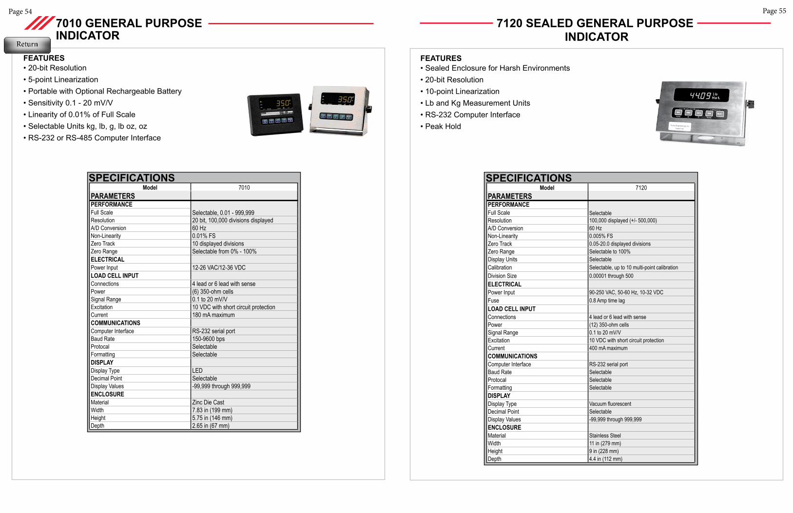
Page 55Page 54
Model 7010PARAMETERS PERFORMANCE Full Scale Selectable, 0.01 - 999,999Resolution 20 bit, 100,000 divisions displayedA/D Conversion 60 HzNon-Linearity 0.01% FSZero Track 10 displayed divisionsZero Range Selectable from 0% - 100%ELECTRICALPower Input 12-26 VAC/12-36 VDCLOAD CELL INPUTConnections 4 lead or 6 lead with sensePower (6) 350-ohm cellsSignal Range 0.1 to 20 mV/VExcitation 10 VDC with short circuit protectionCurrent 180 mA maximumCOMMUNICATIONSComputer Interface RS-232 serial portBaud Rate 150-9600 bpsProtocal SelectableFormatting SelectableDISPLAYDisplay Type LEDDecimal Point SelectableDisplay Values -99,999 through 999,999ENCLOSUREMaterial Zinc Die CastWidth 7.83 in (199 mm)Height 5.75 in (146 mm)Depth 2.65 in (67 mm)
SPECIFICATIONS
FEATURES• 20-bit Resolution • 5-point Linearization• Portable with Optional Rechargeable Battery• Sensitivity 0.1 - 20 mV/V• Linearity of 0.01% of Full Scale• Selectable Units kg, lb, g, lb oz, oz• RS-232 or RS-485 Computer Interface
7010 GENERAL PURPOSE INDICATOR
7120 SEALED GENERAL PURPOSE INDICATOR
FEATURES• Sealed Enclosure for Harsh Environments• 20-bit Resolution • 10-point Linearization• Lb and Kg Measurement Units• RS-232 Computer Interface• Peak Hold
Model 7120PARAMETERS PERFORMANCE Full Scale SelectableResolution 100,000 displayed (+/- 500,000)A/D Conversion 60 HzNon-Linearity 0.005% FSZero Track 0.05-20.0 displayed divisionsZero Range Selectable to 100% Display Units SelectableCalibration Selectable, up to 10 multi-point calibrationDivision Size 0.00001 through 500ELECTRICALPower Input 90-250 VAC, 50-60 Hz, 10-32 VDCFuse 0.8 Amp time lagLOAD CELL INPUTConnections 4 lead or 6 lead with sensePower (12) 350-ohm cellsSignal Range 0.1 to 20 mV/VExcitation 10 VDC with short circuit protectionCurrent 400 mA maximumCOMMUNICATIONSComputer Interface RS-232 serial portBaud Rate SelectableProtocal SelectableFormatting SelectableDISPLAYDisplay Type Vacuum fluorescentDecimal Point SelectableDisplay Values -99,999 through 999,999ENCLOSUREMaterial Stainless SteelWidth 11 in (279 mm)Height 9 in (228 mm)Depth 4.4 in (112 mm)
SPECIFICATIONS
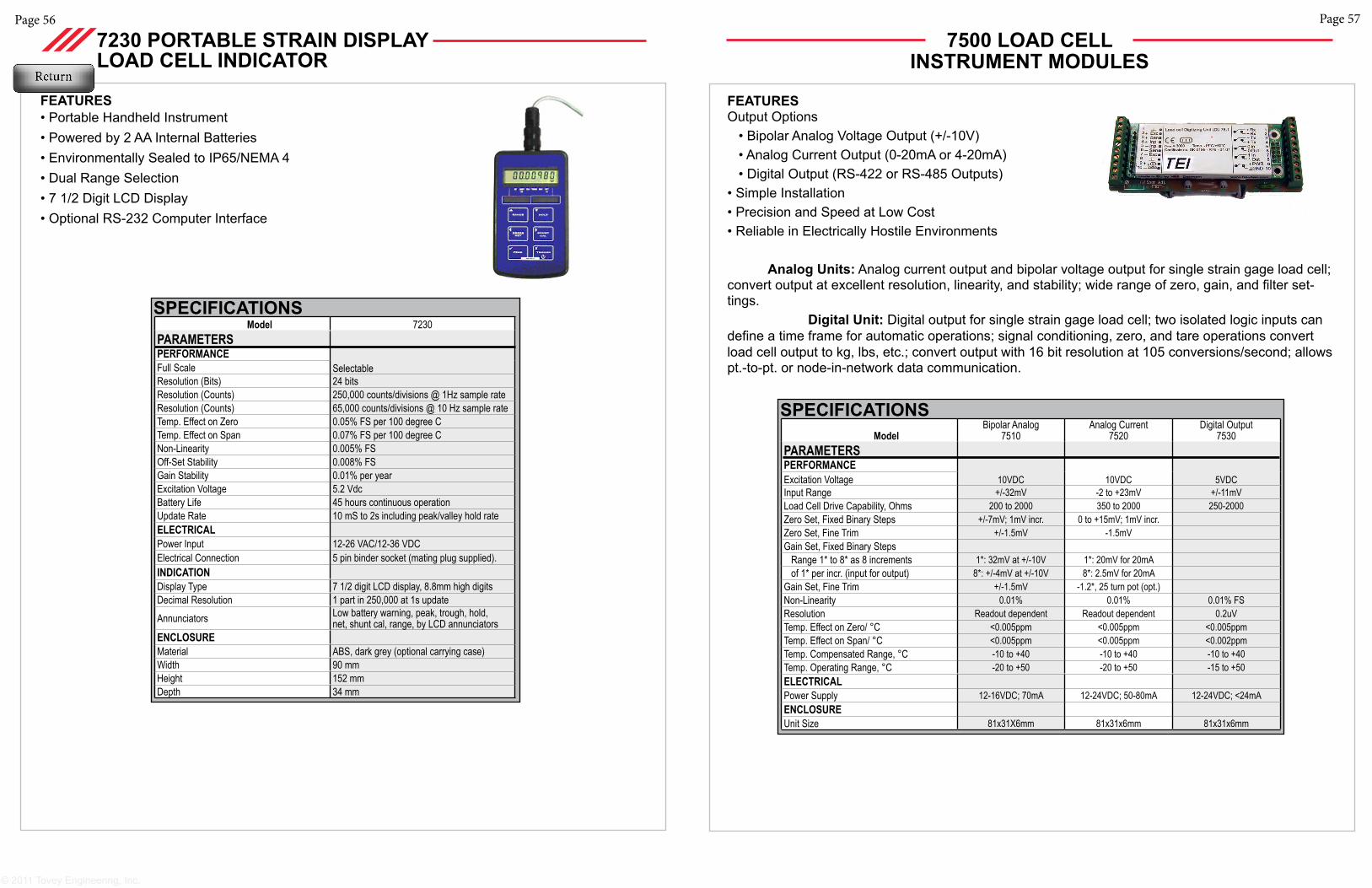
Page 57Page 56
© 2011 Tovey Engineering, Inc.
Model 7230PARAMETERS PERFORMANCE Full Scale SelectableResolution (Bits) 24 bitsResolution (Counts) 250,000 counts/divisions @ 1Hz sample rateResolution (Counts) 65,000 counts/divisions @ 10 Hz sample rateTemp. Effect on Zero 0.05% FS per 100 degree CTemp. Effect on Span 0.07% FS per 100 degree CNon-Linearity 0.005% FSOff-Set Stability 0.008% FSGain Stability 0.01% per yearExcitation Voltage 5.2 VdcBattery Life 45 hours continuous operationUpdate Rate 10 mS to 2s including peak/valley hold rateELECTRICALPower Input 12-26 VAC/12-36 VDCElectrical Connection 5 pin binder socket (mating plug supplied).INDICATIONDisplay Type 7 1/2 digit LCD display, 8.8mm high digitsDecimal Resolution 1 part in 250,000 at 1s updateAnnunciators Low battery warning, peak, trough, hold,
net, shunt cal, range, by LCD annunciatorsENCLOSUREMaterial ABS, dark grey (optional carrying case)Width 90 mmHeight 152 mmDepth 34 mm
SPECIFICATIONS
FEATURES• Portable Handheld Instrument• Powered by 2 AA Internal Batteries• Environmentally Sealed to IP65/NEMA 4• Dual Range Selection• 7 1/2 Digit LCD Display• Optional RS-232 Computer Interface
7230 PORTABLE STRAIN DISPLAYLOAD CELL INDICATOR
FEATURESOutput Options • Bipolar Analog Voltage Output (+/-10V) • Analog Current Output (0-20mA or 4-20mA) • Digital Output (RS-422 or RS-485 Outputs)• Simple Installation• Precision and Speed at Low Cost• Reliable in Electrically Hostile Environments Analog Units: Analog current output and bipolar voltage output for single strain gage load cell; convert output at excellent resolution, linearity, and stability; wide range of zero, gain, and filter set-tings. Digital Unit: Digital output for single strain gage load cell; two isolated logic inputs can define a time frame for automatic operations; signal conditioning, zero, and tare operations convert load cell output to kg, lbs, etc.; convert output with 16 bit resolution at 105 conversions/second; allows pt.-to-pt. or node-in-network data communication.
ModelBipolar Analog
7510Analog Current
7520Digital Output
7530PARAMETERS PERFORMANCEExcitation Voltage 10VDC 10VDC 5VDCInput Range +/-32mV -2 to +23mV +/-11mVLoad Cell Drive Capability, Ohms 200 to 2000 350 to 2000 250-2000Zero Set, Fixed Binary Steps +/-7mV; 1mV incr. 0 to +15mV; 1mV incr.Zero Set, Fine Trim +/-1.5mV -1.5mVGain Set, Fixed Binary Steps Range 1* to 8* as 8 increments 1*: 32mV at +/-10V 1*: 20mV for 20mA of 1* per incr. (input for output) 8*: +/-4mV at +/-10V 8*: 2.5mV for 20mAGain Set, Fine Trim +/-1.5mV -1.2*, 25 turn pot (opt.)Non-Linearity 0.01% 0.01% 0.01% FSResolution Readout dependent Readout dependent 0.2uVTemp. Effect on Zero/ °C <0.005ppm <0.005ppm <0.005ppmTemp. Effect on Span/ °C <0.005ppm <0.005ppm <0.002ppmTemp. Compensated Range, °C -10 to +40 -10 to +40 -10 to +40Temp. Operating Range, °C -20 to +50 -20 to +50 -15 to +50ELECTRICALPower Supply 12-16VDC; 70mA 12-24VDC; 50-80mA 12-24VDC; <24mAENCLOSUREUnit Size 81x31X6mm 81x31x6mm 81x31x6mm
SPECIFICATIONS
7500 LOAD CELL INSTRUMENT MODULES
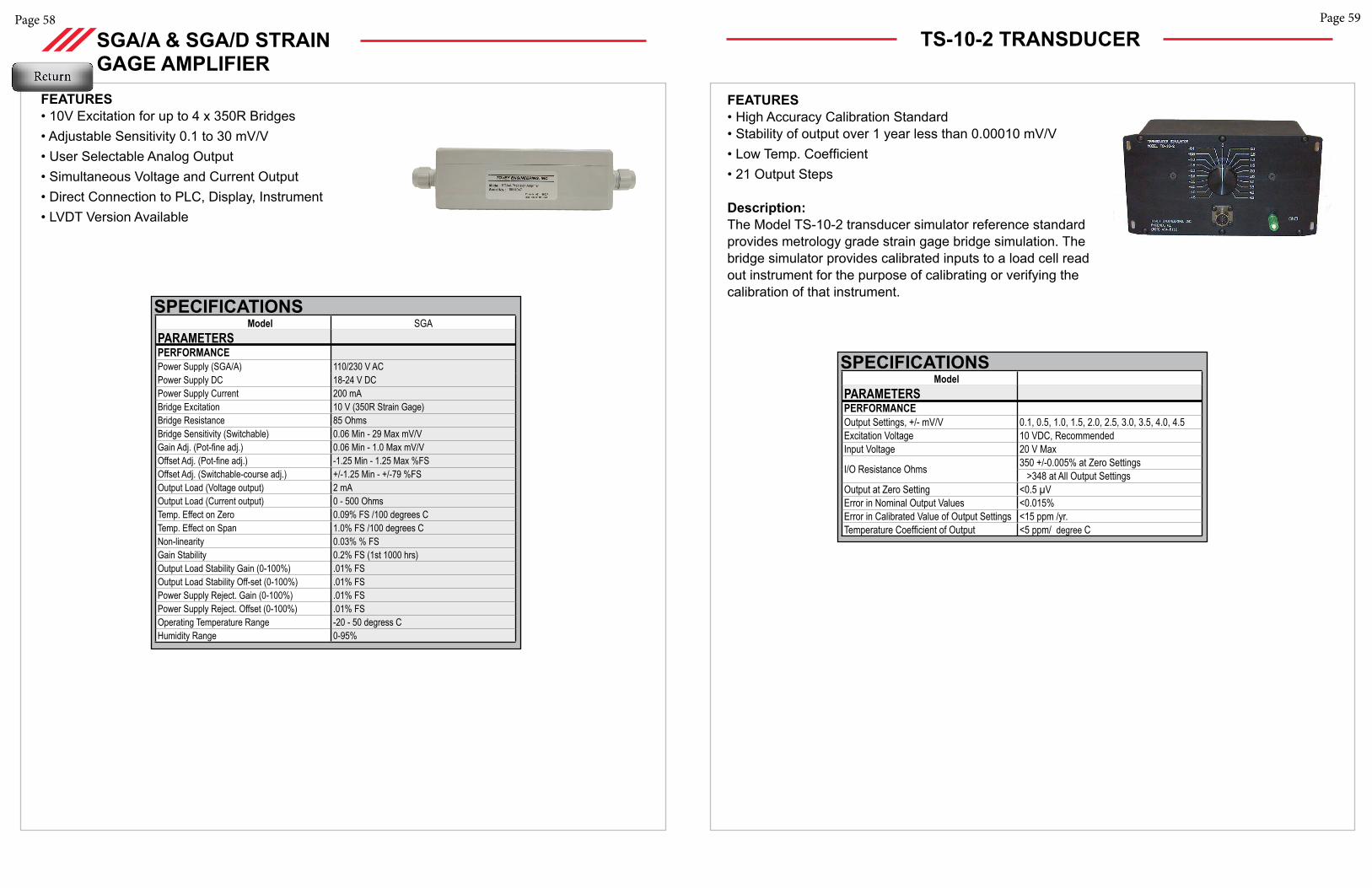
Page 58
SGA/A & SGA/D STRAIN GAGE AMPLIFIER
FEATURES• 10V Excitation for up to 4 x 350R Bridges• Adjustable Sensitivity 0.1 to 30 mV/V• User Selectable Analog Output• Simultaneous Voltage and Current Output• Direct Connection to PLC, Display, Instrument• LVDT Version Available
Model SGAPARAMETERS PERFORMANCE Power Supply (SGA/A) 110/230 V ACPower Supply DC 18-24 V DCPower Supply Current 200 mABridge Excitation 10 V (350R Strain Gage)Bridge Resistance 85 OhmsBridge Sensitivity (Switchable) 0.06 Min - 29 Max mV/VGain Adj. (Pot-fine adj.) 0.06 Min - 1.0 Max mV/VOffset Adj. (Pot-fine adj.) -1.25 Min - 1.25 Max %FSOffset Adj. (Switchable-course adj.) +/-1.25 Min - +/-79 %FSOutput Load (Voltage output) 2 mAOutput Load (Current output) 0 - 500 OhmsTemp. Effect on Zero 0.09% FS /100 degrees CTemp. Effect on Span 1.0% FS /100 degrees CNon-linearity 0.03% % FS Gain Stability 0.2% FS (1st 1000 hrs) Output Load Stability Gain (0-100%) .01% FSOutput Load Stability Off-set (0-100%) .01% FSPower Supply Reject. Gain (0-100%) .01% FSPower Supply Reject. Offset (0-100%) .01% FSOperating Temperature Range -20 - 50 degress CHumidity Range 0-95%
SPECIFICATIONS
Page 59
TS-10-2 TRANSDUCER
ModelPARAMETERS PERFORMANCE Output Settings, +/- mV/V 0.1, 0.5, 1.0, 1.5, 2.0, 2.5, 3.0, 3.5, 4.0, 4.5Excitation Voltage 10 VDC, RecommendedInput Voltage 20 V Max
I/O Resistance Ohms 350 +/-0.005% at Zero Settings >348 at All Output Settings
Output at Zero Setting <0.5 µV Error in Nominal Output Values <0.015%Error in Calibrated Value of Output Settings <15 ppm /yr.Temperature Coefficient of Output <5 ppm/ degree C
SPECIFICATIONS
FEATURES • High Accuracy Calibration Standard• Stability of output over 1 year less than 0.00010 mV/V• Low Temp. Coefficient • 21 Output Steps
Description:The Model TS-10-2 transducer simulator reference standard provides metrology grade strain gage bridge simulation. The bridge simulator provides calibrated inputs to a load cell read out instrument for the purpose of calibrating or verifying the calibration of that instrument.
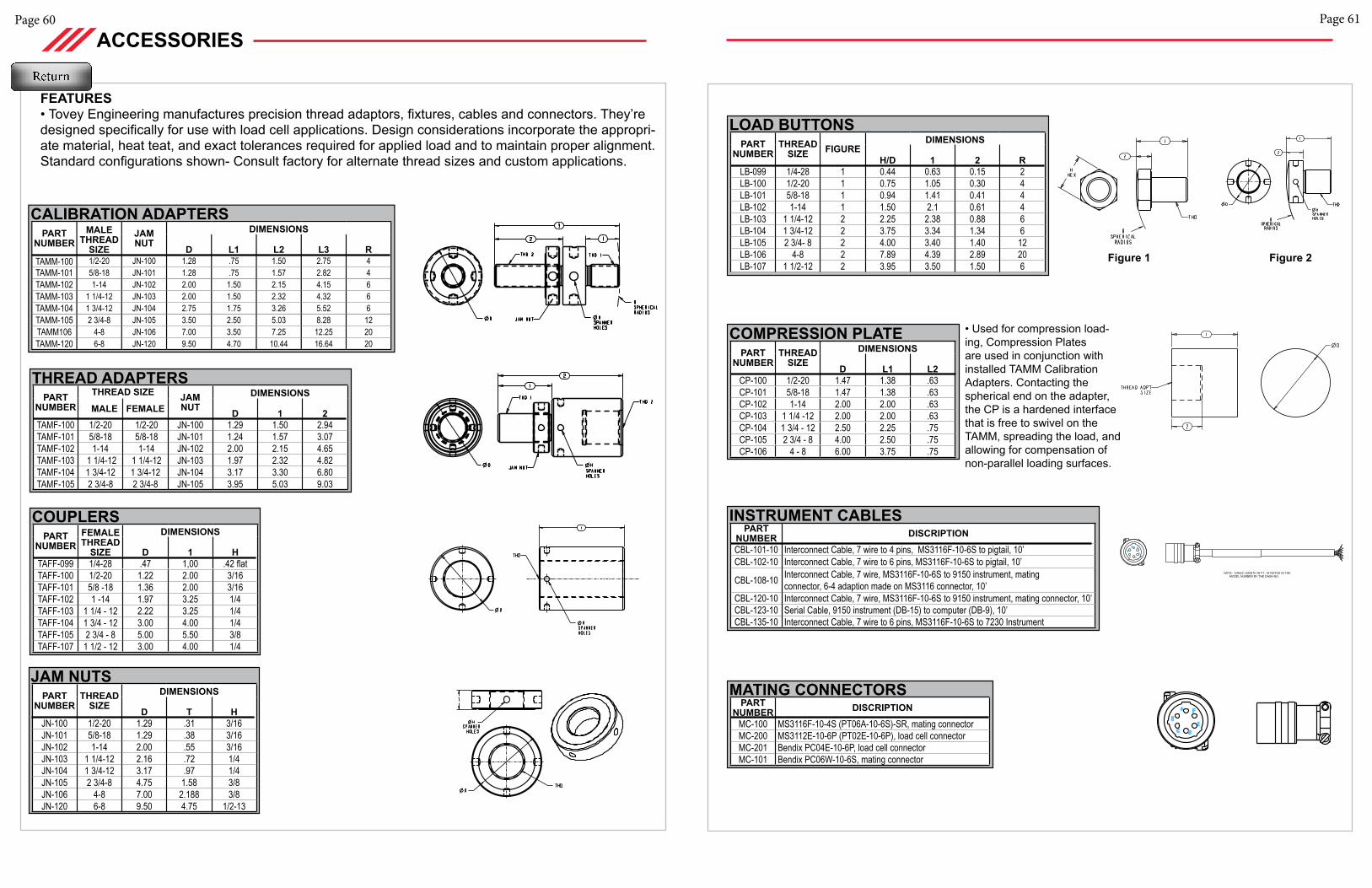
Page 61Page 60
ACCESSORIES
FEATURES• Tovey Engineering manufactures precision thread adaptors, fixtures, cables and connectors. They’re designed specifically for use with load cell applications. Design considerations incorporate the appropri-ate material, heat teat, and exact tolerances required for applied load and to maintain proper alignment. Standard configurations shown- Consult factory for alternate thread sizes and custom applications.
PART NUMBER
MALE THREAD
SIZE JAM NUT
DIMENSIONS
D L1 L2 L3 RTAMM-100 1/2-20 JN-100 1.28 .75 1.50 2.75 4TAMM-101 5/8-18 JN-101 1.28 .75 1.57 2.82 4TAMM-102 1-14 JN-102 2.00 1.50 2.15 4.15 6TAMM-103 1 1/4-12 JN-103 2.00 1.50 2.32 4.32 6TAMM-104 1 3/4-12 JN-104 2.75 1.75 3.26 5.52 6TAMM-105 2 3/4-8 JN-105 3.50 2.50 5.03 8.28 12TAMM106 4-8 JN-106 7.00 3.50 7.25 12.25 20TAMM-120 6-8 JN-120 9.50 4.70 10.44 16.64 20
CALIBRATION ADAPTERS
PART NUMBER
THREAD SIZE JAM NUT
DIMENSIONS MALE FEMALE D 1 2
TAMF-100 1/2-20 1/2-20 JN-100 1.29 1.50 2.94TAMF-101 5/8-18 5/8-18 JN-101 1.24 1.57 3.07TAMF-102 1-14 1-14 JN-102 2.00 2.15 4.65TAMF-103 1 1/4-12 1 1/4-12 JN-103 1.97 2.32 4.82TAMF-104 1 3/4-12 1 3/4-12 JN-104 3.17 3.30 6.80TAMF-105 2 3/4-8 2 3/4-8 JN-105 3.95 5.03 9.03
THREAD ADAPTERS
PART NUMBER
FEMALE THREAD
SIZE
DIMENSIONS
D 1 HTAFF-099 1/4-28 .47 1,00 .42 flatTAFF-100 1/2-20 1.22 2.00 3/16TAFF-101 5/8 -18 1.36 2.00 3/16TAFF-102 1 -14 1.97 3.25 1/4TAFF-103 1 1/4 - 12 2.22 3.25 1/4TAFF-104 1 3/4 - 12 3.00 4.00 1/4TAFF-105 2 3/4 - 8 5.00 5.50 3/8TAFF-107 1 1/2 - 12 3.00 4.00 1/4
COUPLERS
PART NUMBER
THREAD SIZE
DIMENSIONS
D T HJN-100 1/2-20 1.29 .31 3/16JN-101 5/8-18 1.29 .38 3/16JN-102 1-14 2.00 .55 3/16JN-103 1 1/4-12 2.16 .72 1/4JN-104 1 3/4-12 3.17 .97 1/4JN-105 2 3/4-8 4.75 1.58 3/8JN-106 4-8 7.00 2.188 3/8JN-120 6-8 9.50 4.75 1/2-13
JAM NUTS
PART NUMBER
THREAD SIZE FIGURE
DIMENSIONS
H/D 1 2 RLB-099 1/4-28 1 0.44 0.63 0.15 2LB-100 1/2-20 1 0.75 1.05 0.30 4LB-101 5/8-18 1 0.94 1.41 0.41 4LB-102 1-14 1 1.50 2.1 0.61 4LB-103 1 1/4-12 2 2.25 2.38 0.88 6LB-104 1 3/4-12 2 3.75 3.34 1.34 6LB-105 2 3/4- 8 2 4.00 3.40 1.40 12LB-106 4-8 2 7.89 4.39 2.89 20LB-107 1 1/2-12 2 3.95 3.50 1.50 6
LOAD BUTTONS
Figure 1 Figure 2
PART NUMBER DISCRIPTION
CBL-101-10 Interconnect Cable, 7 wire to 4 pins, MS3116F-10-6S to pigtail, 10’CBL-102-10 Interconnect Cable, 7 wire to 6 pins, MS3116F-10-6S to pigtail, 10’
CBL-108-10 Interconnect Cable, 7 wire, MS3116F-10-6S to 9150 instrument, mating connector, 6-4 adaption made on MS3116 connector, 10’
CBL-120-10 Interconnect Cable, 7 wire, MS3116F-10-6S to 9150 instrument, mating connector, 10’CBL-123-10 Serial Cable, 9150 instrument (DB-15) to computer (DB-9), 10’CBL-135-10 Interconnect Cable, 7 wire to 6 pins, MS3116F-10-6S to 7230 Instrument
INSTRUMENT CABLES
PART NUMBER DISCRIPTION
MC-100 MS3116F-10-4S (PT06A-10-6S)-SR, mating connectorMC-200 MS3112E-10-6P (PT02E-10-6P), load cell connectorMC-201 Bendix PC04E-10-6P, load cell connectorMC-101 Bendix PC06W-10-6S, mating connector
MATING CONNECTORS
PART NUMBER
THREAD SIZE
DIMENSIONS
D L1 L2CP-100 1/2-20 1.47 1.38 .63CP-101 5/8-18 1.47 1.38 .63CP-102 1-14 2.00 2.00 .63CP-103 1 1/4 -12 2.00 2.00 .63CP-104 1 3/4 - 12 2.50 2.25 .75CP-105 2 3/4 - 8 4.00 2.50 .75CP-106 4 - 8 6.00 3.75 .75
COMPRESSION PLATE
NOTE: CABLE LENGTH IN FT., IS NOTED IN THE MODEL NUMBER BY THE DASH NO.
• Used for compression load-ing, Compression Plates are used in conjunction with installed TAMM Calibration Adapters. Contacting the spherical end on the adapter, the CP is a hardened interface that is free to swivel on the TAMM, spreading the load, and allowing for compensation of non-parallel loading surfaces.
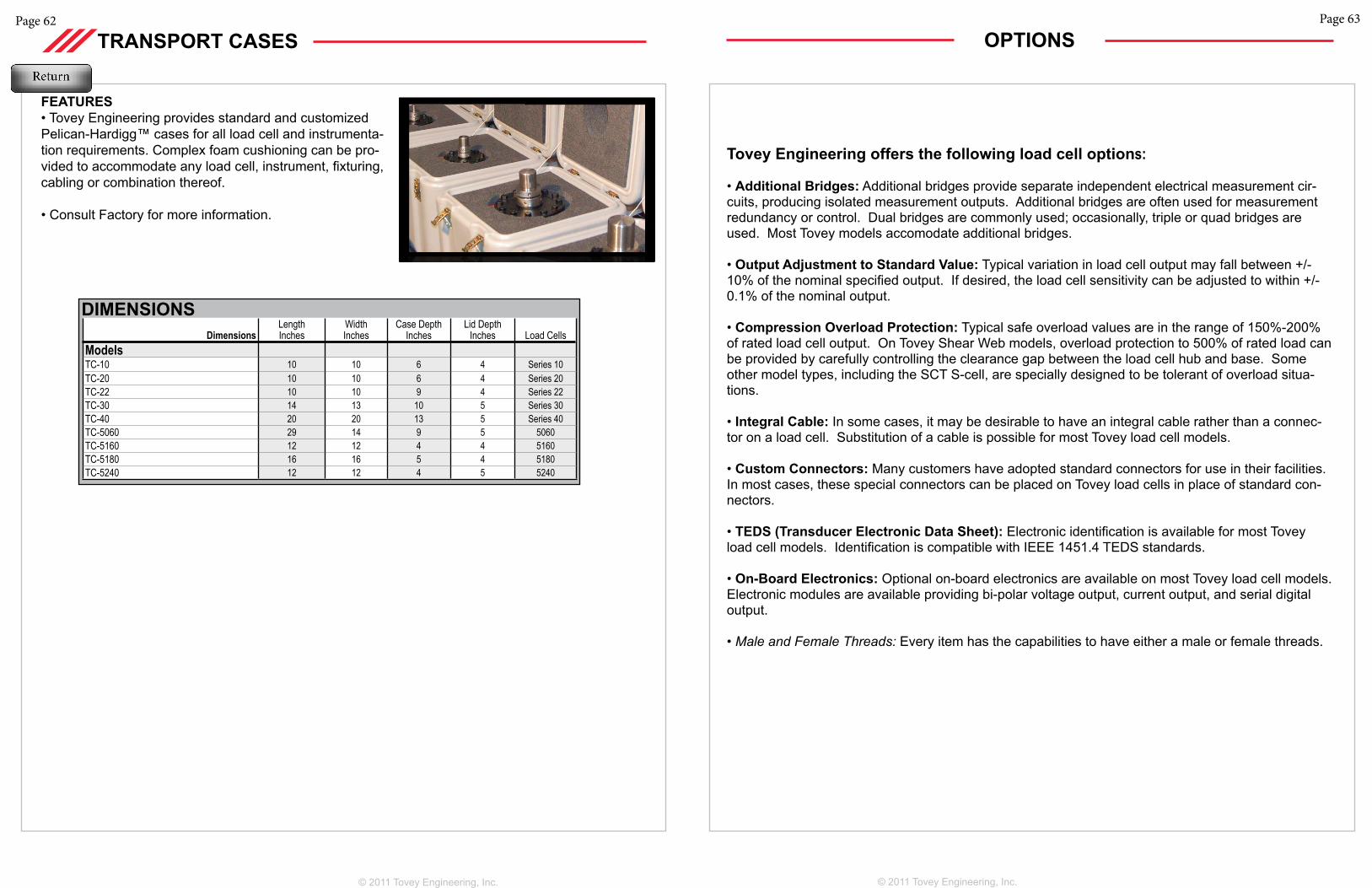
Page 63
© 2011 Tovey Engineering, Inc.
OPTIONS
Tovey Engineering offers the following load cell options:
• Additional Bridges: Additional bridges provide separate independent electrical measurement cir-cuits, producing isolated measurement outputs. Additional bridges are often used for measurement redundancy or control. Dual bridges are commonly used; occasionally, triple or quad bridges are used. Most Tovey models accomodate additional bridges.
• Output Adjustment to Standard Value: Typical variation in load cell output may fall between +/-10% of the nominal specified output. If desired, the load cell sensitivity can be adjusted to within +/-0.1% of the nominal output.
• Compression Overload Protection: Typical safe overload values are in the range of 150%-200% of rated load cell output. On Tovey Shear Web models, overload protection to 500% of rated load can be provided by carefully controlling the clearance gap between the load cell hub and base. Some other model types, including the SCT S-cell, are specially designed to be tolerant of overload situa-tions.
• Integral Cable: In some cases, it may be desirable to have an integral cable rather than a connec-tor on a load cell. Substitution of a cable is possible for most Tovey load cell models.
• Custom Connectors: Many customers have adopted standard connectors for use in their facilities. In most cases, these special connectors can be placed on Tovey load cells in place of standard con-nectors.
• TEDS (Transducer Electronic Data Sheet): Electronic identification is available for most Tovey load cell models. Identification is compatible with IEEE 1451.4 TEDS standards.
• On-Board Electronics: Optional on-board electronics are available on most Tovey load cell models. Electronic modules are available providing bi-polar voltage output, current output, and serial digital output.
• Male and Female Threads: Every item has the capabilities to have either a male or female threads.
Page 62
TRANSPORT CASES
FEATURES• Tovey Engineering provides standard and customized Pelican-Hardigg™ cases for all load cell and instrumenta-tion requirements. Complex foam cushioning can be pro-vided to accommodate any load cell, instrument, fixturing, cabling or combination thereof.
• Consult Factory for more information.
DIMENSIONSDimensions
Length Inches
Width Inches
Case DepthInches
Lid Depth Inches Load Cells
Models TC-10 10 10 6 4 Series 10TC-20 10 10 6 4 Series 20TC-22 10 10 9 4 Series 22TC-30 14 13 10 5 Series 30TC-40 20 20 13 5 Series 40TC-5060 29 14 9 5 5060TC-5160 12 12 4 4 5160TC-5180 16 16 5 4 5180TC-5240 12 12 4 5 5240
© 2011 Tovey Engineering, Inc.
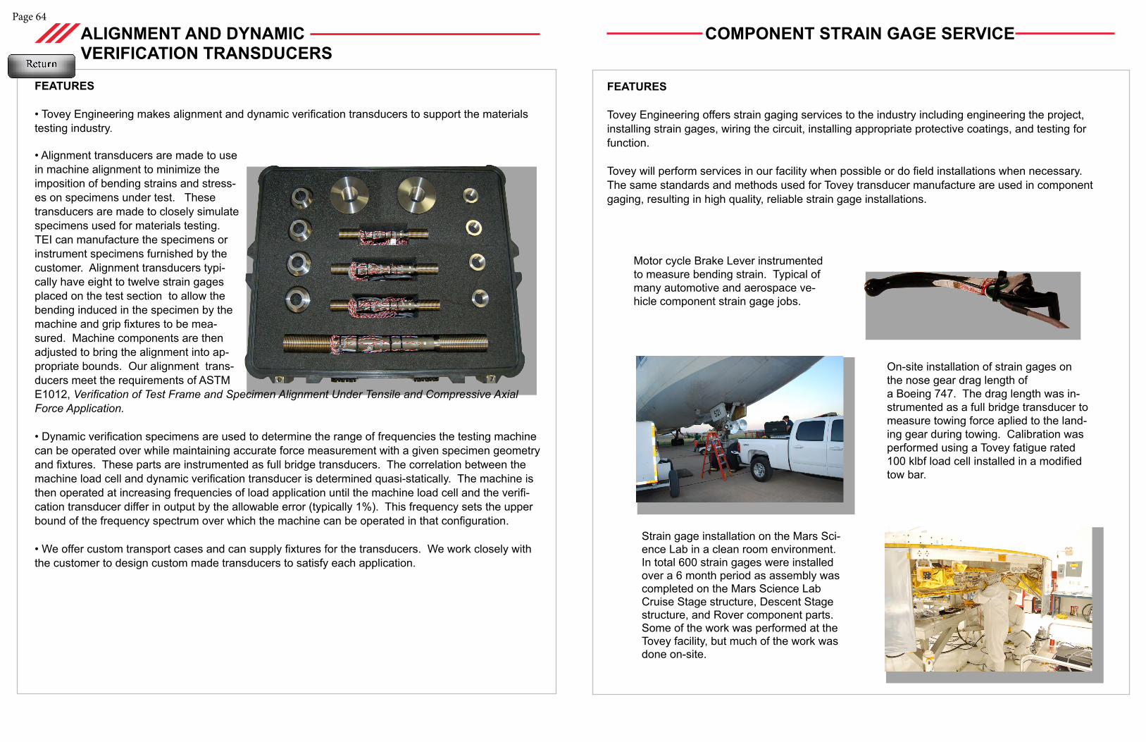
COMPONENT STRAIN GAGE SERVICE
Page 64
ALIGNMENT AND DYNAMIC VERIFICATION TRANSDUCERS
FEATURES
• Tovey Engineering makes alignment and dynamic verification transducers to support the materials testing industry.
• Alignment transducers are made to use in machine alignment to minimize the imposition of bending strains and stress-es on specimens under test. These transducers are made to closely simulate specimens used for materials testing. TEI can manufacture the specimens or instrument specimens furnished by the customer. Alignment transducers typi-cally have eight to twelve strain gages placed on the test section to allow the bending induced in the specimen by the machine and grip fixtures to be mea-sured. Machine components are then adjusted to bring the alignment into ap-propriate bounds. Our alignment trans-ducers meet the requirements of ASTM E1012, Verification of Test Frame and Specimen Alignment Under Tensile and Compressive Axial Force Application.
• Dynamic verification specimens are used to determine the range of frequencies the testing machine can be operated over while maintaining accurate force measurement with a given specimen geometry and fixtures. These parts are instrumented as full bridge transducers. The correlation between the machine load cell and dynamic verification transducer is determined quasi-statically. The machine is then operated at increasing frequencies of load application until the machine load cell and the verifi-cation transducer differ in output by the allowable error (typically 1%). This frequency sets the upper bound of the frequency spectrum over which the machine can be operated in that configuration.
• We offer custom transport cases and can supply fixtures for the transducers. We work closely with the customer to design custom made transducers to satisfy each application.
On-site installation of strain gages on the nose gear drag length of a Boeing 747. The drag length was in-strumented as a full bridge transducer to measure towing force aplied to the land-ing gear during towing. Calibration was performed using a Tovey fatigue rated 100 klbf load cell installed in a modified tow bar.
Strain gage installation on the Mars Sci-ence Lab in a clean room environment. In total 600 strain gages were installed over a 6 month period as assembly was completed on the Mars Science Lab Cruise Stage structure, Descent Stage structure, and Rover component parts. Some of the work was performed at the Tovey facility, but much of the work was done on-site.
FEATURES
Tovey Engineering offers strain gaging services to the industry including engineering the project, installing strain gages, wiring the circuit, installing appropriate protective coatings, and testing for function.
Tovey will perform services in our facility when possible or do field installations when necessary. The same standards and methods used for Tovey transducer manufacture are used in component gaging, resulting in high quality, reliable strain gage installations.
Motor cycle Brake Lever instrumented to measure bending strain. Typical of many automotive and aerospace ve-hicle component strain gage jobs.
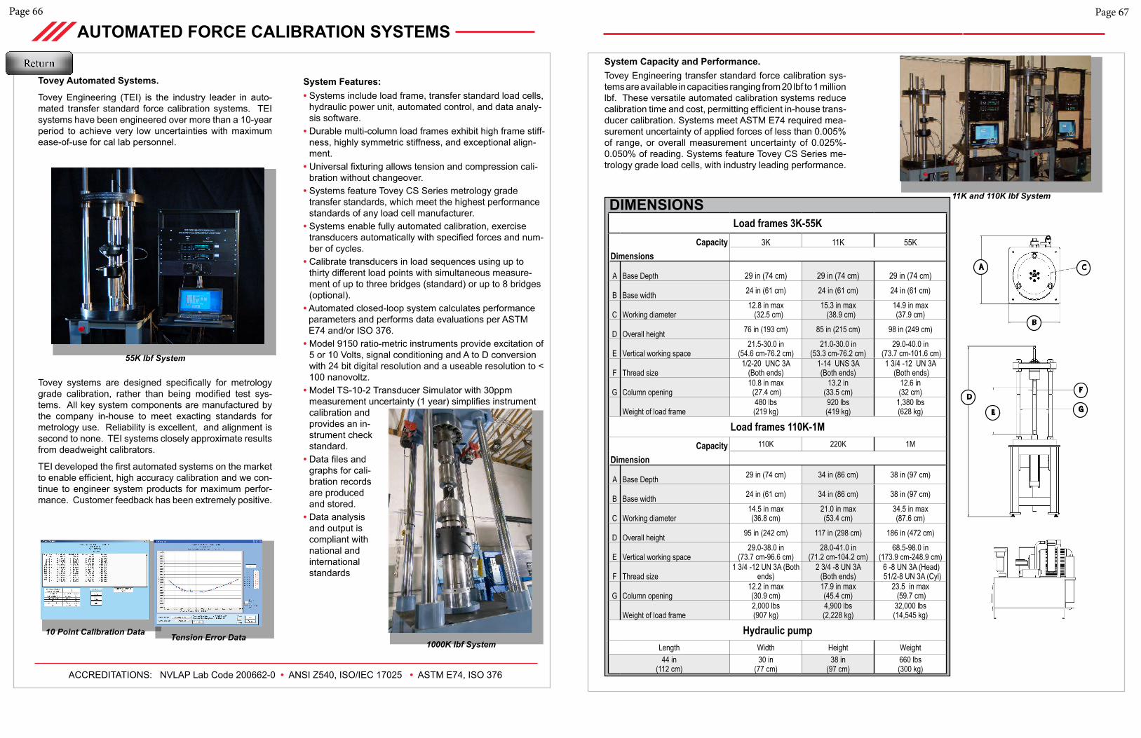
Page 66
AUTOMATED FORCE CALIBRATION SYSTEMS
Tovey Automated Systems.
Tovey Engineering (TEI) is the industry leader in auto-mated transfer standard force calibration systems. TEI systems have been engineered over more than a 10-year period to achieve very low uncertainties with maximum ease-of-use for cal lab personnel.
Tovey systems are designed specifically for metrology grade calibration, rather than being modified test sys-tems. All key system components are manufactured by the company in-house to meet exacting standards for metrology use. Reliability is excellent, and alignment is second to none. TEI systems closely approximate results from deadweight calibrators.
TEI developed the first automated systems on the market to enable efficient, high accuracy calibration and we con-tinue to engineer system products for maximum perfor-mance. Customer feedback has been extremely positive.
55K lbf System
1000K lbf System10 Point Calibration Data Tension Error Data
System Features:• Systems include load frame, transfer standard load cells,
hydraulic power unit, automated control, and data analy-sis software.
• Durable multi-column load frames exhibit high frame stiff-ness, highly symmetric stiffness, and exceptional align-ment.
• Universal fixturing allows tension and compression cali-bration without changeover.
• Systems feature Tovey CS Series metrology grade transfer standards, which meet the highest performance standards of any load cell manufacturer.
• Systems enable fully automated calibration, exercise transducers automatically with specified forces and num-ber of cycles.
• Calibrate transducers in load sequences using up to thirty different load points with simultaneous measure-ment of up to three bridges (standard) or up to 8 bridges (optional).
• Automated closed-loop system calculates performance parameters and performs data evaluations per ASTM E74 and/or ISO 376.• Model 9150 ratio-metric instruments provide excitation of
5 or 10 Volts, signal conditioning and A to D conversion with 24 bit digital resolution and a useable resolution to < 100 nanovoltz.
• Model TS-10-2 Transducer Simulator with 30ppm measurement uncertainty (1 year) simplifies instrument calibration and provides an in-strument check standard.
• Data files and graphs for cali-bration records are produced and stored.
• Data analysis and output is compliant with national and international standards
ACCREDITATIONS: NVLAP Lab Code 200662-0 • ANSI Z540, ISO/IEC 17025 • ASTM E74, ISO 376
Page 67
11K and 110K lbf System
System Capacity and Performance. Tovey Engineering transfer standard force calibration sys-tems are available in capacities ranging from 20 lbf to 1 million lbf. These versatile automated calibration systems reduce calibration time and cost, permitting efficient in-house trans-ducer calibration. Systems meet ASTM E74 required mea-surement uncertainty of applied forces of less than 0.005% of range, or overall measurement uncertainty of 0.025%-0.050% of reading. Systems feature Tovey CS Series me-trology grade load cells, with industry leading performance.
Load frames 3K-55KCapacity 3K 11K 55K
Dimensions
A Base Depth 29 in (74 cm) 29 in (74 cm) 29 in (74 cm)
B Base width 24 in (61 cm) 24 in (61 cm) 24 in (61 cm)
C Working diameter12.8 in max (32.5 cm)
15.3 in max (38.9 cm)
14.9 in max (37.9 cm)
D Overall height 76 in (193 cm) 85 in (215 cm) 98 in (249 cm)
E Vertical working space 21.5-30.0 in
(54.6 cm-76.2 cm)21.0-30.0 in
(53.3 cm-76.2 cm)29.0-40.0 in
(73.7 cm-101.6 cm)
F Thread size1/2-20 UNC 3A
(Both ends)1-14 UNS 3A (Both ends)
1 3/4 -12 UN 3A (Both ends)
G Column opening10.8 in max (27.4 cm)
13.2 in (33.5 cm)
12.6 in (32 cm)
Weight of load frame480 lbs (219 kg)
920 lbs (419 kg)
1,380 lbs (628 kg)
Load frames 110K-1MCapacity 110K 220K 1M
Dimension
A Base Depth 29 in (74 cm) 34 in (86 cm) 38 in (97 cm)
B Base width 24 in (61 cm) 34 in (86 cm) 38 in (97 cm)
C Working diameter14.5 in max (36.8 cm)
21.0 in max (53.4 cm)
34.5 in max (87.6 cm)
D Overall height 95 in (242 cm) 117 in (298 cm) 186 in (472 cm)
E Vertical working space 29.0-38.0 in
(73.7 cm-96.6 cm)28.0-41.0 in
(71.2 cm-104.2 cm)68.5-98.0 in
(173.9 cm-248.9 cm)
F Thread size1 3/4 -12 UN 3A (Both
ends)2 3/4 -8 UN 3A
(Both ends) 6 -8 UN 3A (Head) 51/2-8 UN 3A (Cyl)
G Column opening12.2 in max (30.9 cm)
17.9 in max (45.4 cm)
23.5 in max (59.7 cm)
Weight of load frame2,000 lbs (907 kg)
4,900 lbs (2,228 kg)
32,000 lbs (14,545 kg)
Hydraulic pumpLength Width Height Weight44 in
(112 cm)30 in
(77 cm)38 in
(97 cm)660 lbs (300 kg)
DIMENSIONS
Load frames 3K-55K Dimension Capacity > 3K 11K 55K
A Base Depth 29 in (74 cm) 29 in (74 cm) 29 in (74 cm)
B Base width 24 in (61 cm) 24 in (61 cm) 24 in (61 cm)
C Working diameter
12.8 in max (32.5 cm)
15.3 in max (38.9 cm)
14.9 in max (37.9 cm)
D Overall height 76 in (193 cm) 85 in (215 cm) 98 in (249 cm)
E Vertical working space
21.5-30.0 in (54.6 cm-76.2 cm)
21.0-30.0 in (53.3 cm-76.2 cm)
29.0-40.0 in (73.7 cm-101.6 cm)
F Thread size 1/2-20 UNC 3A (Both ends)
1-14 UNS 3A (Both ends)
1 3/4 -12 UN 3A (Both ends)
G Column opening
10.8 in max (27.4 cm) 13.2 in (33.5 cm) 12.6 in (32 cm)
Weight of load frame
480 lbs (219 kg)
920 lbs (419 kg)
1,380 lbs (628 kg)
Load frames 110K-1M Dimension Capacity > 110K 220K 1M
A Base Depth 29 in (74 cm) 34 in (86 cm) 38 in (97 cm)
B Base width 24 in (61 cm) 34 in (86 cm) 38 in (97 cm)
C Working diameter
14.5 in max (36.8 cm)
21.0 in max (53.4 cm)
34.5 in max (87.6 cm)
D Overall height 95 in (242 cm) 117 in (298 cm) 186 in (472 cm)
E Vertical working space
29.0-38.0 in (73.7 cm-96.6 cm)
28.0-41.0 in (71.2 cm-104.2 cm)
68.5-98.0 in (174 cm -249 cm)
F Thread size 1 3/4 -12 UN 3A (Both ends)
2 3/4 - 8 UN 3A (Both ends)
6 -8 UN 3A (Head) 51/2-8 UN 3A (Cyl)
G Column opening
12.2 in max (30.9 cm)
17.9 in max (45.4 cm)
23.5 in max (59.7 cm)
Weight of load frame
2,000 lbs (907 kg)
4,900 lbs (2,228 kg)
32,000 lbs (14,545 kg)
Hydraulic pump Length Width Height Weight Electrical Pressure
44 in (112 cm)
30 in (77 cm)
38 in (97 cm)
660 lbs (300 kg) 10 HP 4000 psi max
(282 kg/cm)
DIMENSIONS
A
B
C
G
F
E
D
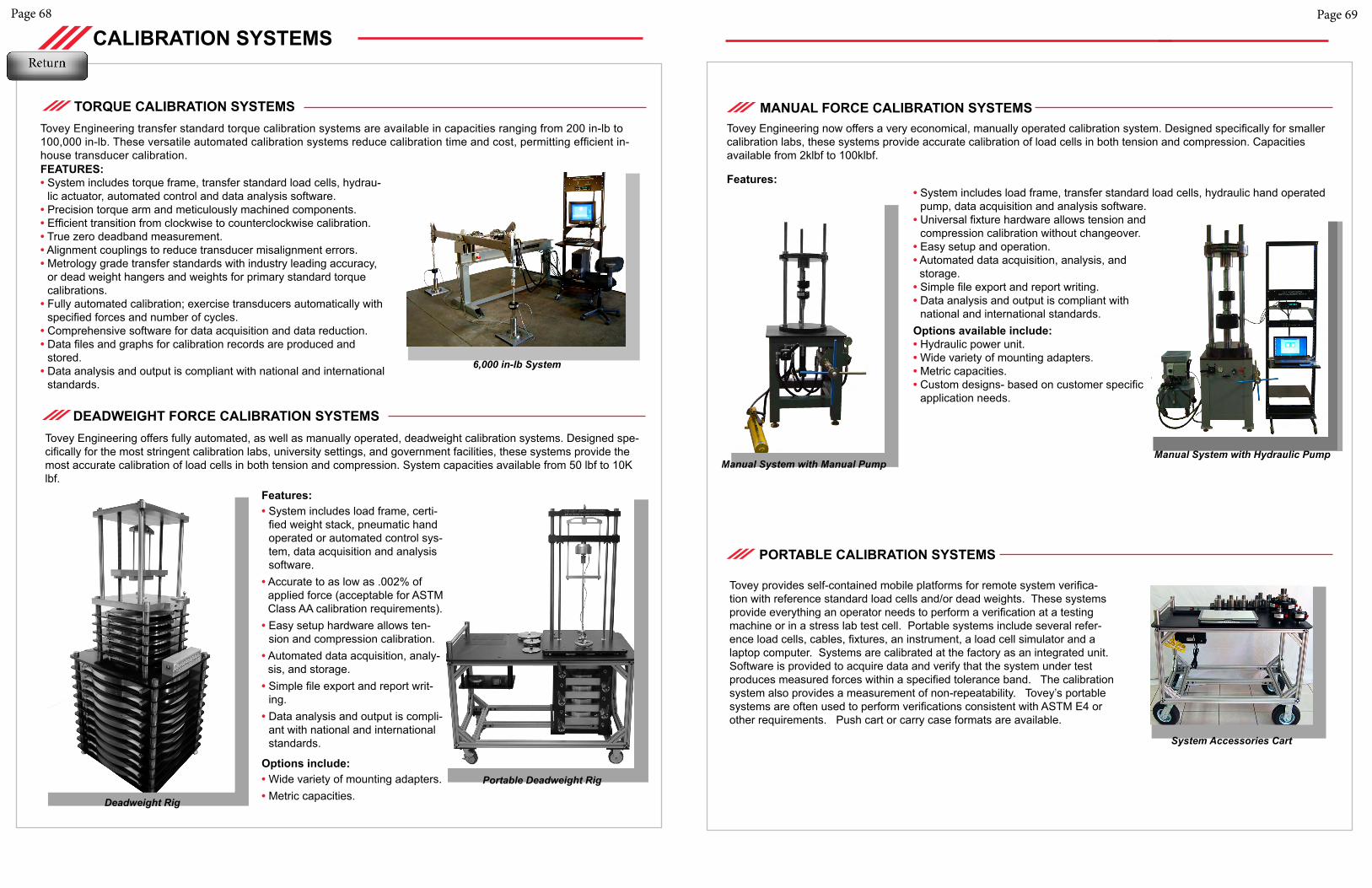
Page 68
CALIBRATION SYSTEMS
FEATURES:• System includes torque frame, transfer standard load cells, hydrau-
lic actuator, automated control and data analysis software.• Precision torque arm and meticulously machined components.• Efficient transition from clockwise to counterclockwise calibration.• True zero deadband measurement.• Alignment couplings to reduce transducer misalignment errors.• Metrology grade transfer standards with industry leading accuracy,
or dead weight hangers and weights for primary standard torque calibrations.
• Fully automated calibration; exercise transducers automatically with specified forces and number of cycles.
• Comprehensive software for data acquisition and data reduction.• Data files and graphs for calibration records are produced and
stored.• Data analysis and output is compliant with national and international
standards.
TORQUE CALIBRATION SYSTEMSTovey Engineering transfer standard torque calibration systems are available in capacities ranging from 200 in-lb to 100,000 in-lb. These versatile automated calibration systems reduce calibration time and cost, permitting efficient in-house transducer calibration.
6,000 in-lb System
Tovey Engineering offers fully automated, as well as manually operated, deadweight calibration systems. Designed spe-cifically for the most stringent calibration labs, university settings, and government facilities, these systems provide the most accurate calibration of load cells in both tension and compression. System capacities available from 50 lbf to 10K lbf.
Features:• System includes load frame, certi-
fied weight stack, pneumatic hand operated or automated control sys-tem, data acquisition and analysis software.
• Accurate to as low as .002% of applied force (acceptable for ASTM Class AA calibration requirements).• Easy setup hardware allows ten-
sion and compression calibration. • Automated data acquisition, analy-
sis, and storage.• Simple file export and report writ-
ing.• Data analysis and output is compli-
ant with national and international standards.
Options include:• Wide variety of mounting adapters.• Metric capacities.
Portable Deadweight Rig
DEADWEIGHT FORCE CALIBRATION SYSTEMS
Page 69
Features:• System includes load frame, transfer standard load cells, hydraulic hand operated
pump, data acquisition and analysis software.• Universal fixture hardware allows tension and
compression calibration without changeover.• Easy setup and operation.• Automated data acquisition, analysis, and
storage.• Simple file export and report writing.• Data analysis and output is compliant with
national and international standards.Options available include:• Hydraulic power unit.• Wide variety of mounting adapters.• Metric capacities.• Custom designs- based on customer specific
application needs.
MANUAL FORCE CALIBRATION SYSTEMS
PORTABLE CALIBRATION SYSTEMS
System Accessories Cart
Tovey provides self-contained mobile platforms for remote system verifica-tion with reference standard load cells and/or dead weights. These systems provide everything an operator needs to perform a verification at a testing machine or in a stress lab test cell. Portable systems include several refer-ence load cells, cables, fixtures, an instrument, a load cell simulator and a laptop computer. Systems are calibrated at the factory as an integrated unit. Software is provided to acquire data and verify that the system under test produces measured forces within a specified tolerance band. The calibration system also provides a measurement of non-repeatability. Tovey’s portable systems are often used to perform verifications consistent with ASTM E4 or other requirements. Push cart or carry case formats are available.
Deadweight Rig
Manual System with Hydraulic Pump
Tovey Engineering now offers a very economical, manually operated calibration system. Designed specifically for smaller calibration labs, these systems provide accurate calibration of load cells in both tension and compression. Capacities available from 2klbf to 100klbf.
Manual System with Manual Pump
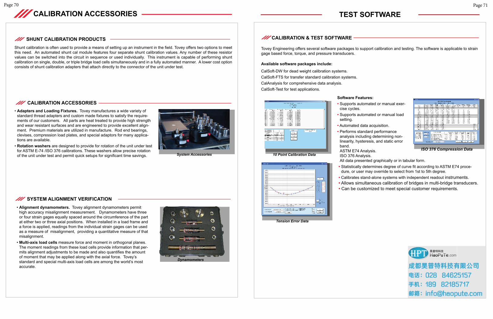
Page 71
TEST SOFTWARE
Available software packages include:
CalSoft-DW for dead weight calibration systems.CalSoft-FTS for transfer standard calibration systems.CalAnalysis for comprehensive data analysis. CalSoft-Test for test applications.
Software Features:• Supports automated or manual exer-
cise cycles.• Supports automated or manual load
setting.• Automated data acquisition.• Performs standard performance
analysis including determining non-linearity, hysteresis, and static error band. ASTM E74 Analysis. ISO 376 Analysis. All data presented graphically or in tabular form.• Statistically determines degree of curve fit according to ASTM E74 proce-
dure, or user may override to select from 1st to 5th degree.• Calibrates stand-alone systems with independent readout instruments.• Allows simultaneous calibration of bridges in multi-bridge transducers.• Can be customized to meet special customer requirements.
Page 70
CALIBRATION ACCESSORIES
• Adapters and Loading Fixtures. Tovey manufactures a wide variety of standard thread adapters and custom made fixtures to satisfy the require-ments of our customers. All parts are heat treated to provide high strength and wear resistant surfaces and are engineered to provide excellent align-ment. Premium materials are utilized in manufacture. Rod end bearings, clevises, compression load plates, and special adaptors for many applica-tions are available.
• Rotation washers are designed to provide for rotation of the unit under test for ASTM E-74 /ISO 376 calibrations. These washers allow precise rotation of the unit under test and permit quick setups for significant time savings.
Dynamometers
System Accessories
CALIBRATION ACCESSORIES
• Alignment dynamometers. Tovey alignment dynamometers permit high accuracy misalignment measurement. Dynamometers have three or four strain gages equally spaced around the circumference of the part at either two or three axial positions. When installed in a load frame and a force is applied, readings from the individual strain gages can be used as a measure of misalignment, providing a quantitative measure of that misalignment.
• Multi-axis load cells measure force and moment in orthogonal planes. The moment readings from these load cells provide information that per-mits alignment adjustments to be made and also quantifies the amount of moment that may be applied along with the axial force. Tovey’s standard and special multi-axis load cells are among the world’s most accurate.
SYSTEM ALIGNMENT VERIFICATION
Shunt calibration is often used to provide a means of setting up an instrument in the field. Tovey offers two options to meet this need. An automated shunt cal module features four separate shunt calibration values. Any number of these resistor values can be switched into the circuit in sequence or used individually. This instrument is capable of performing shunt calibration on single, double, or triple bridge load cells simultaneously and in a fully automated manner. A lower cost option consists of shunt calibration adapters that attach directly to the connector of the unit under test.
SHUNT CALIBRATION PRODUCTS
10 Point Calibration Data
Tension Error Data
ISO 376 Compression Data
CALIBRATION & TEST SOFTWARE
Tovey Engineering offers several software packages to support calibration and testing. The software is applicable to strain gage based force, torque, and pressure transducers.