Embed Size (px)
Citation preview
FPGA in Data Acquisition Using cRIO and LabVIEW:
User Manual
Joanne Sirois and Joe Voelmle
Dr. Zalewski CDA 4104
May 2, 2009
2
Table of Contents
1. Introduction ........................................................................................................................................... 3
2. Working with NI 9401 .......................................................................................................................... 4
2.1 Introduction ................................................................................................................................... 4
2.2 Running the Example Program ..................................................................................................... 6
3. Working with NI 9263 ........................................................................................................................ 10
3.1 Introduction ................................................................................................................................. 10
3.2 Running the Example Program ................................................................................................... 10
4. Working with NI 9205 ........................................................................................................................ 14
4.1 Introduction ................................................................................................................................. 14
4.2 Running the Example Program ................................................................................................... 15
5. Conclusion .......................................................................................................................................... 20
References ................................................................................................................................................... 22
Appendix A ................................................................................................................................................. 23
Data Acquisition using the cRIO-9074 FPGA Modules ......................................................................... 23
Creating a VI for NI 9401 ................................................................................................................... 23
Creating a VI using NI 9263 ............................................................................................................... 32
Creating a VI using NI 9205 ............................................................................................................... 34
Appendix B ................................................................................................................................................. 36
3
1. Introduction
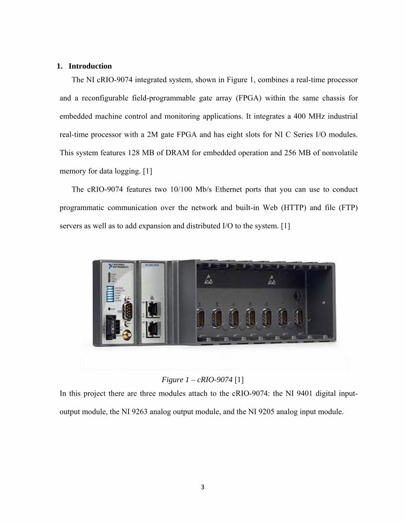
The NI cRIO-9074 integrated system, shown in Figure 1, combines a real-time processor
and a reconfigurable field-programmable gate array (FPGA) within the same chassis for
embedded machine control and monitoring applications. It integrates a 400 MHz industrial
real-time processor with a 2M gate FPGA and has eight slots for NI C Series I/O modules.
This system features 128 MB of DRAM for embedded operation and 256 MB of nonvolatile
memory for data logging. [1]
The cRIO-9074 features two 10/100 Mb/s Ethernet ports that you can use to conduct
programmatic communication over the network and built-in Web (HTTP) and file (FTP)
servers as well as to add expansion and distributed I/O to the system. [1]
Figure 1 – cRIO-9074 [1]
In this project there are three modules attach to the cRIO-9074: the NI 9401 digital input-
output module, the NI 9263 analog output module, and the NI 9205 analog input module.
4
2. Working with NI 9401
2.1 Introduction
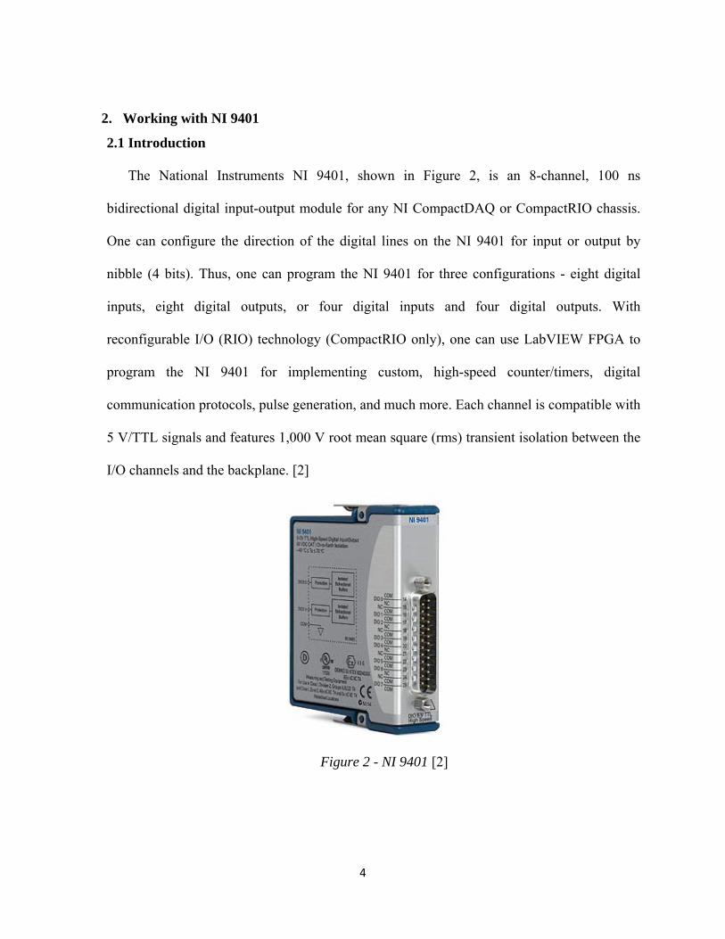
The National Instruments NI 9401, shown in Figure 2, is an 8-channel, 100 ns
bidirectional digital input-output module for any NI CompactDAQ or CompactRIO chassis.
One can configure the direction of the digital lines on the NI 9401 for input or output by
nibble (4 bits). Thus, one can program the NI 9401 for three configurations - eight digital
inputs, eight digital outputs, or four digital inputs and four digital outputs. With
reconfigurable I/O (RIO) technology (CompactRIO only), one can use LabVIEW FPGA to
program the NI 9401 for implementing custom, high-speed counter/timers, digital
communication protocols, pulse generation, and much more. Each channel is compatible with
5 V/TTL signals and features 1,000 V root mean square (rms) transient isolation between the
I/O channels and the backplane. [2]
Figure 2 - NI 9401 [2]
5
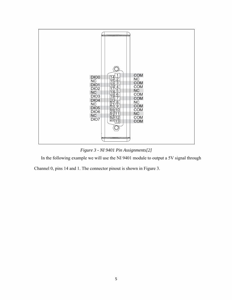
Figure 3 - NI 9401 Pin Assignments[2]
In the following example we will use the NI 9401 module to output a 5V signal through
Channel 0, pins 14 and 1. The connector pinout is shown in Figure 3.
6
2.2 Running the Example Program
Below we present a sequence of steps to run a LabVIEW VI, showing how to use the NI
9401 digital I/O module to send a digital signal to an output line.
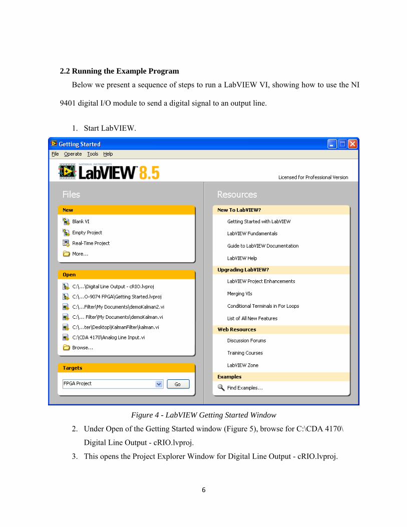
1. Start LabVIEW.
Figure 4 - LabVIEW Getting Started Window
2. Under Open of the Getting Started window (Figure 5), browse for C:\CDA 4170\
Digital Line Output - cRIO.lvproj.
3. This opens the Project Explorer Window for Digital Line Output - cRIO.lvproj.
7
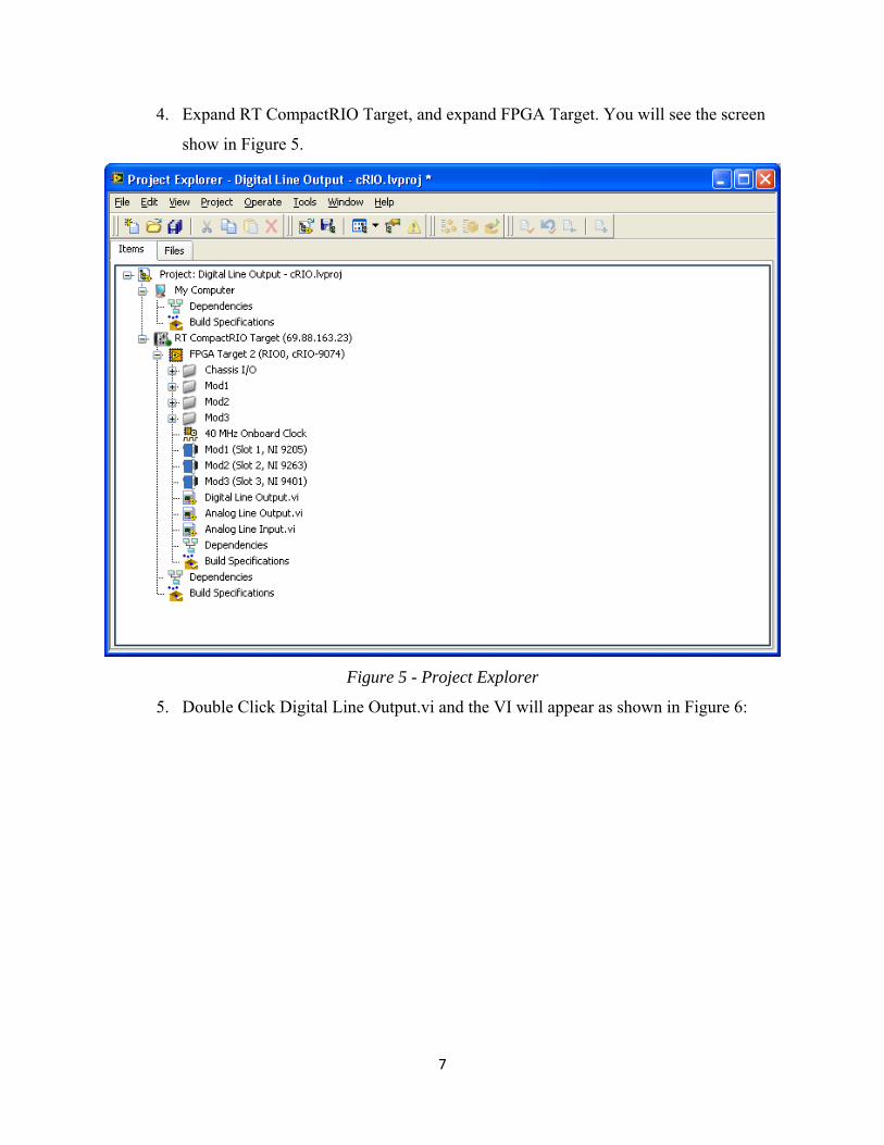
4. Expand RT CompactRIO Target, and expand FPGA Target. You will see the screen
show in Figure 5.
Figure 5 - Project Explorer
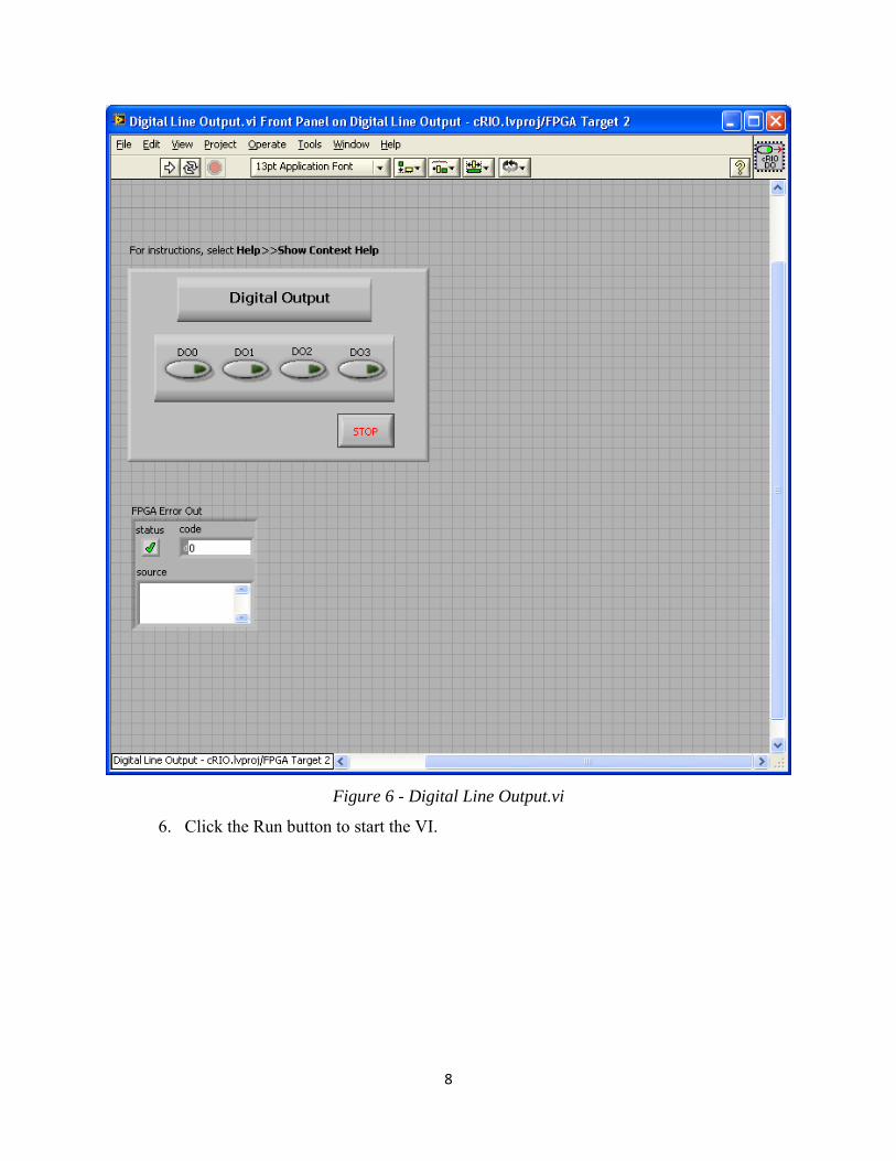
5. Double Click Digital Line Output.vi and the VI will appear as shown in Figure 6:
8
Figure 6 - Digital Line Output.vi
6. Click the Run button to start the VI.
9
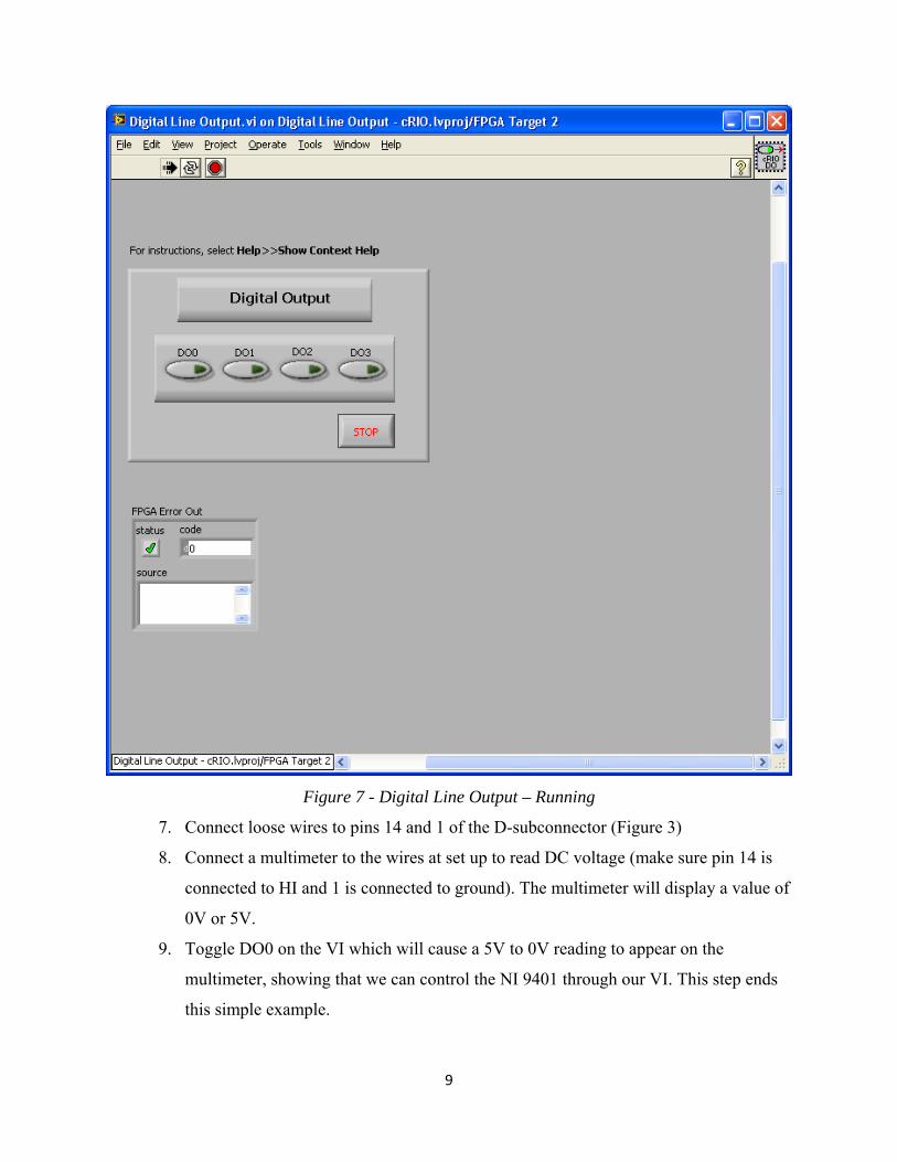
Figure 7 - Digital Line Output – Running
7. Connect loose wires to pins 14 and 1 of the D-subconnector (Figure 3)
8. Connect a multimeter to the wires at set up to read DC voltage (make sure pin 14 is
connected to HI and 1 is connected to ground). The multimeter will display a value of
0V or 5V.
9. Toggle DO0 on the VI which will cause a 5V to 0V reading to appear on the
multimeter, showing that we can control the NI 9401 through our VI. This step ends
this simple example.
10
3. Working with NI 9263
3.1 Introduction
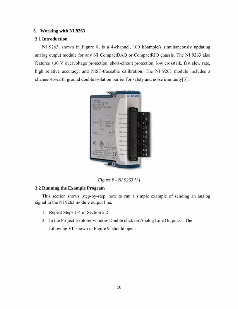
NI 9263, shown in Figure 8, is a 4-channel, 100 kSample/s simultaneously updating
analog output module for any NI CompactDAQ or CompactRIO chassis. The NI 9263 also
features ±30 V overvoltage protection, short-circuit protection, low crosstalk, fast slew rate,
high relative accuracy, and NIST-traceable calibration. The NI 9263 module includes a
channel-to-earth ground double isolation barrier for safety and noise immunity[3].
Figure 8 - NI 9263 [3]
3.2 Running the Example Program
This section shows, step-by-step, how to run a simple example of sending an analog signal to the NI 9263 module output line.
1. Repeat Steps 1-4 of Section 2.2
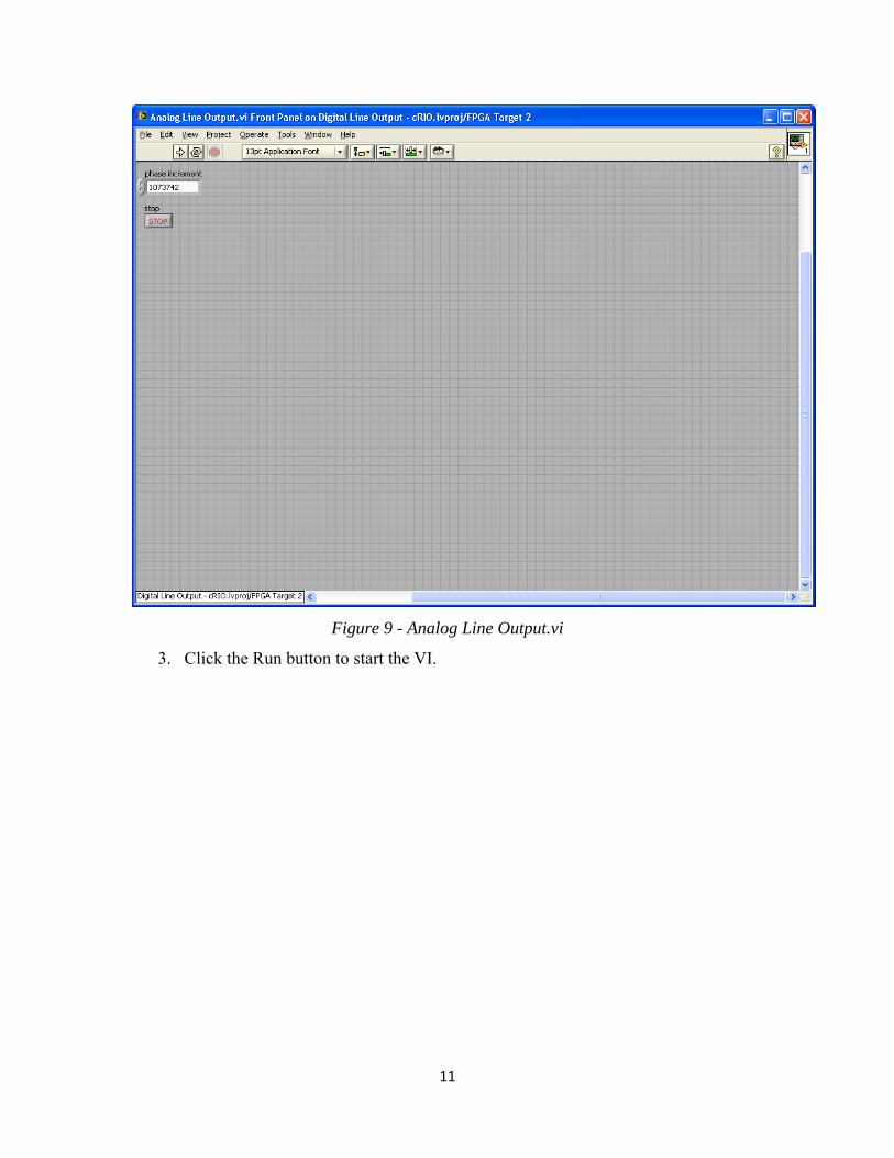
2. In the Project Explorer window Double click on Analog Line Output.vi. The
following VI, shown in Figure 9, should open.
11
Figure 9 - Analog Line Output.vi
3. Click the Run button to start the VI.
12
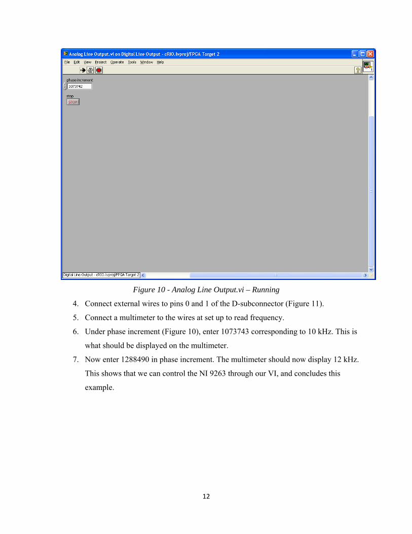
Figure 10 - Analog Line Output.vi – Running
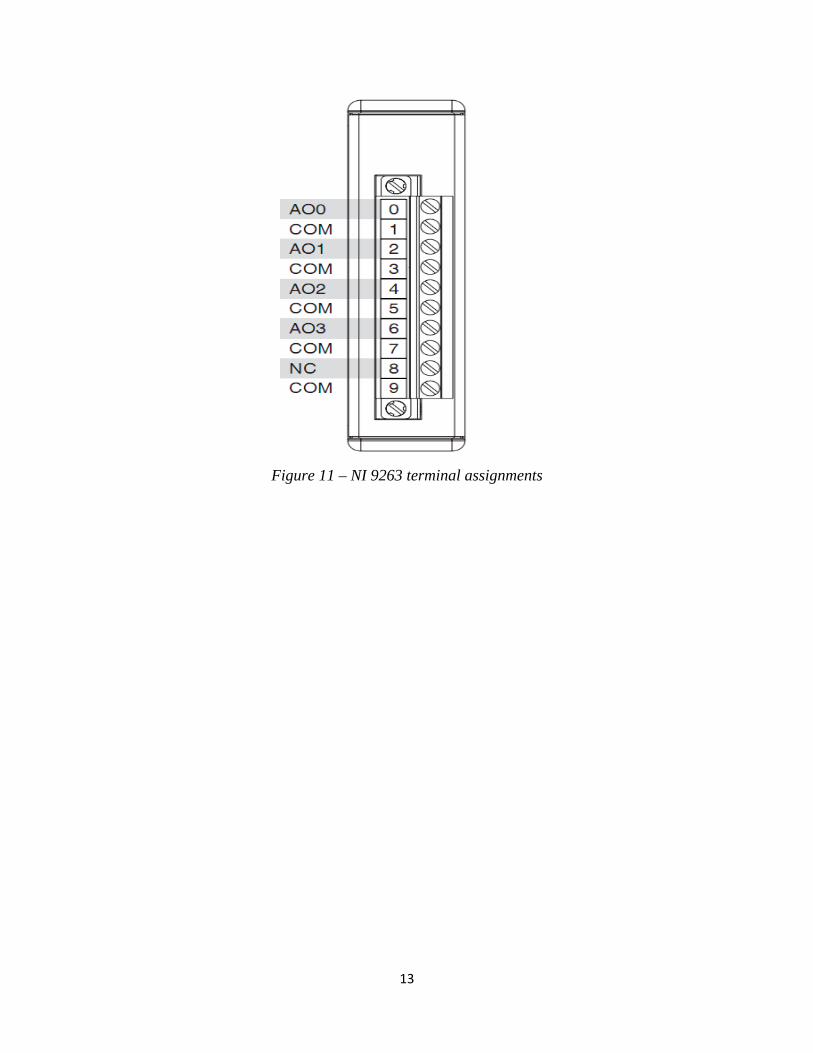
4. Connect external wires to pins 0 and 1 of the D-subconnector (Figure 11).
5. Connect a multimeter to the wires at set up to read frequency.
6. Under phase increment (Figure 10), enter 1073743 corresponding to 10 kHz. This is
what should be displayed on the multimeter.
7. Now enter 1288490 in phase increment. The multimeter should now display 12 kHz.
This shows that we can control the NI 9263 through our VI, and concludes this
example.
13
Figure 11 – NI 9263 terminal assignments
14
4. Working with NI 9205
4.1 Introduction
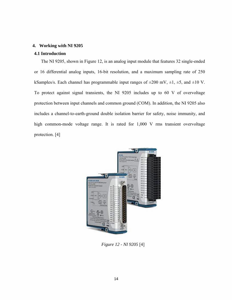
The NI 9205, shown in Figure 12, is an analog input module that features 32 single-ended
or 16 differential analog inputs, 16-bit resolution, and a maximum sampling rate of 250
kSamples/s. Each channel has programmable input ranges of ±200 mV, ±1, ±5, and ±10 V.
To protect against signal transients, the NI 9205 includes up to 60 V of overvoltage
protection between input channels and common ground (COM). In addition, the NI 9205 also
includes a channel-to-earth-ground double isolation barrier for safety, noise immunity, and
high common-mode voltage range. It is rated for 1,000 V rms transient overvoltage
protection. [4]
Figure 12 - NI 9205 [4]
15
4.2 Running the Example Program
This example attempts to show step-by-step how to read an analog input signal from the
NI 9205 with LabVIEW.
1. Repeat Steps 1-4 of Section 2.2
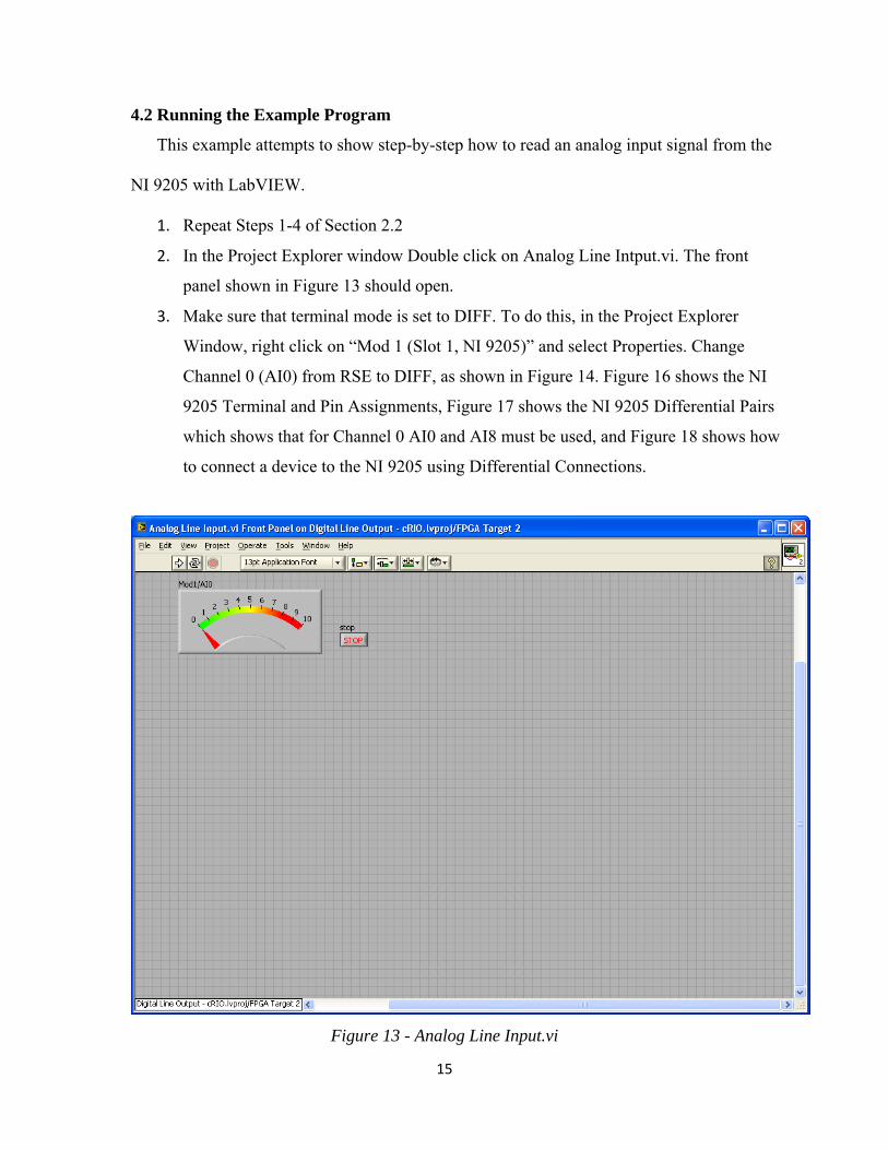
2. In the Project Explorer window Double click on Analog Line Intput.vi. The front
panel shown in Figure 13 should open.
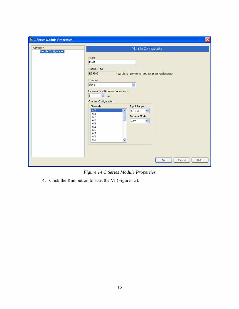
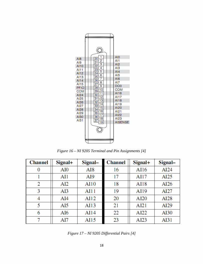
3. Make sure that terminal mode is set to DIFF. To do this, in the Project Explorer
Window, right click on “Mod 1 (Slot 1, NI 9205)” and select Properties. Change
Channel 0 (AI0) from RSE to DIFF, as shown in Figure 14. Figure 16 shows the NI
9205 Terminal and Pin Assignments, Figure 17 shows the NI 9205 Differential Pairs
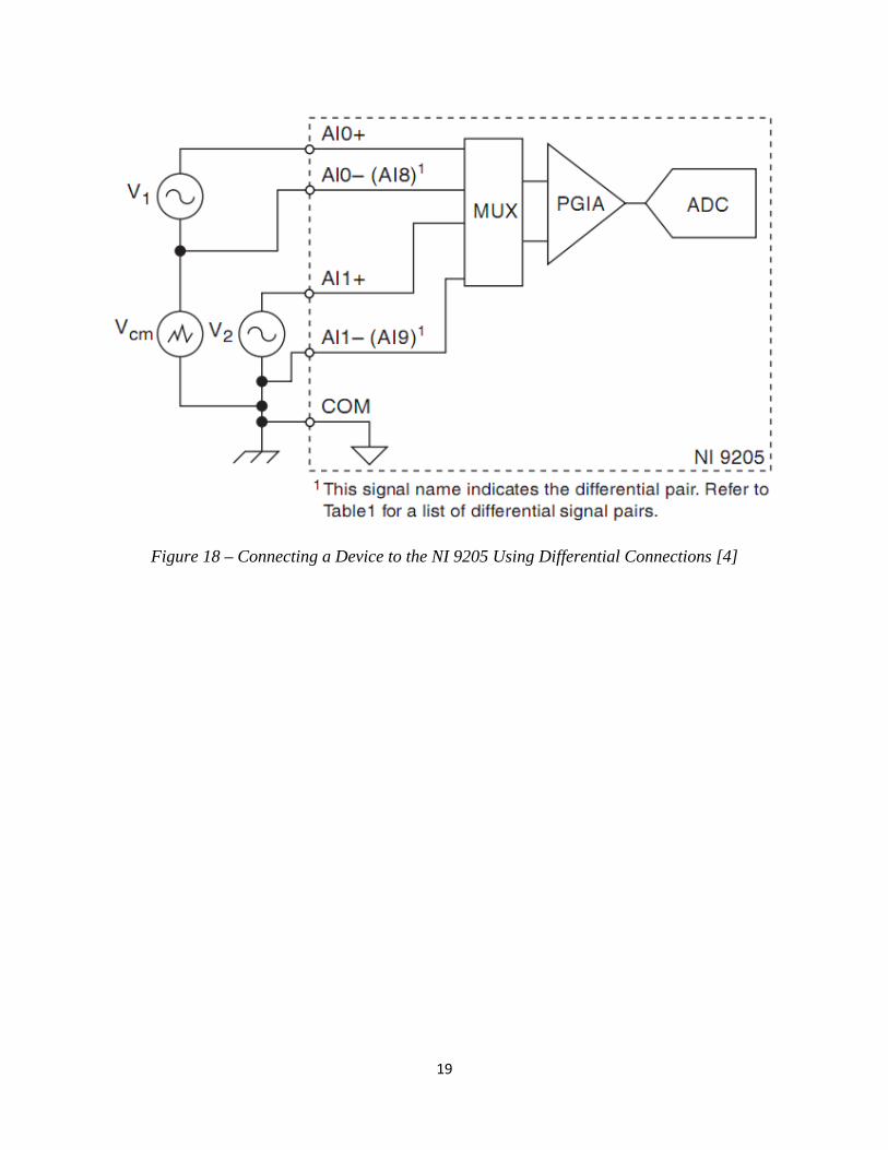
which shows that for Channel 0 AI0 and AI8 must be used, and Figure 18 shows how
to connect a device to the NI 9205 using Differential Connections.
Figure 13 - Analog Line Input.vi
16
Figure 14 C Series Module Properties
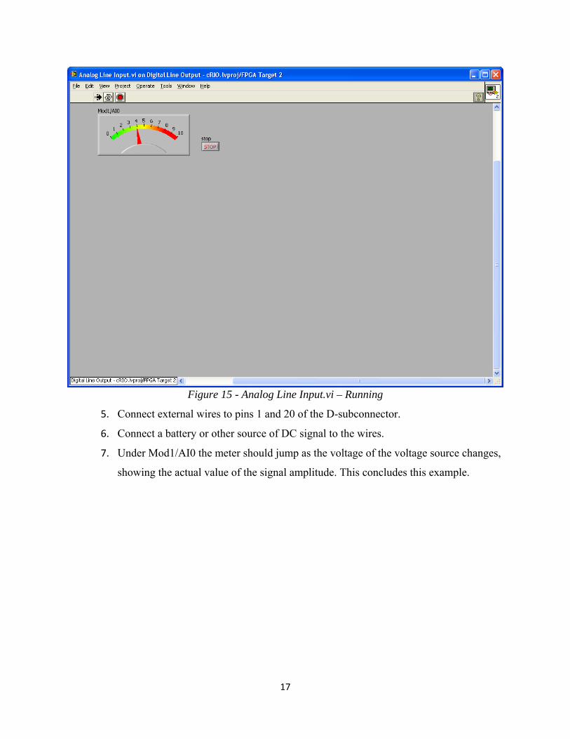
4. Click the Run button to start the VI (Figure 15).
17
Figure 15 - Analog Line Input.vi – Running
5. Connect external wires to pins 1 and 20 of the D-subconnector.
6. Connect a battery or other source of DC signal to the wires.
7. Under Mod1/AI0 the meter should jump as the voltage of the voltage source changes,
showing the actual value of the signal amplitude. This concludes this example.
18
Figure 16 – NI 9205 Terminal and Pin Assignments [4]
Figure 17 – NI 9205 Differential Pairs [4]
19
Figure 18 – Connecting a Device to the NI 9205 Using Differential Connections [4]
20
5. Conclusion
There were several difficulties that were encountered in the course of this project. The
most serious was the lack of availability of resources to use LabVIEW with cRIO and its
FPGA. There seems to be an abundance of information available on the Internet, but no clear
starting point at which a novice can begin. The problem was finally resolved by a phone call
to technical support at National Instruments to walk us through how to create simple VIs in
LabVIEW. However, much time was spent setting up this phone conversation. Days were
spent emailing back and forth to get answers to questions. The authors feel that a more timely
resolution would have been to have a field engineer on sight to conduct a tutorial in creating
LabVIEW VIs using cRIO. Appendix B lists an email detailing how National Instrument
support was used.
As the initial learning curve is overcome, many more substantial VIs can be developed
using CRIO. The rudimentary VIs developed in this report were to gain experience in using
cRIO within the LabVIEW environment. Basic signal acquisition was demonstrated, using
simple voltage sources. As confidence and knowledge is gained in using cRIO, more
substantial data acquisition using sophisticated VIs and advanced transducers should be
possible. Once cRIO and LabVIEW are mastered, it is the authors’ opinion that the design of
advanced data acquisition systems should possible in a much shorter period of time and with
less cost than traditional methods.
LabVIEW provides the user with the ability to integrate applications written in VHDL
code into a LabVIEW FPGA without having to recreate the application in LabVIEW. The
21
user can enter the code in LabVIEW’s HDL Interface Node. This utility creates a LabVIEW
VI or function from the user’s code so that it can be used in the graphical programming
environment of a LabVIEW Block Diagram just like any other VI or function. This saves
development time by allowing the user to the user use proven VHDL code in their
application. More details are given in “Importing HDL Code into FPGA VIs Using the HDL
Interface Node” [7].
22
References
[1] NI cRIO-9074- Products and Services - National Instruments, National Instruments Corp,
Austin, TX, http://sine.ni.com/nips/cds/view/p/lang/en/nid/203964
[2] NI 9401 - Products and Services - National Instruments, National Instruments Corp, Austin,
TX, http://sine.ni.com/nips/cds/view/p/lang/en/nid/205926
[3] NI 9263 - Products and Services - National Instruments, National Instruments Corp, Austin,
TX, http://sine.ni.com/nips/cds/view/p/lang/en/nid/205923
[4] NI 9205 - Products and Services - National Instruments, National Instruments Corp, Austin,
TX, http://sine.ni.com/nips/cds/view/p/lang/en/nid/202571
[5] LabVIEW FPGA and CompactRIO Getting Started Tutorial, National Instruments Corp,
Austin, TX, http://www.ni.com/pdf/labview/us/fpga_compactrio_getting_started.pdf
[6] Getting Results with CompactRIO and LabVIEW, National Instruments Corp, Austin, TX,
2006, http://ftp.uniroma2.it/Natinst/support/ind_comm/manuals/371012c.pdf
[7] Importing HDL Code into FPGA VIs Using the HDL Interface Node, National Instruments
Corp, Austin, TX, 2008, http://zone.ni.com/devzone/cda/tut/p/id/3483
23
Appendix A
Data Acquisition using the cRIO-9074 FPGA Modules
Objective: Three basic programs will be developed to output 5V from the NI 9401,
output Frequency from NI 9263 and read an input voltage from NI 9205.
Background: The student is required to know:
• Chapters 1 & 2 from the Bishop’s textbook, and
• Chapters 1 & 2 from “LabVIEW Getting Started”, as listed in Module #4 Student Activities.
Creating a VI for NI 9401
Adding a new VI for the Digital IO Module
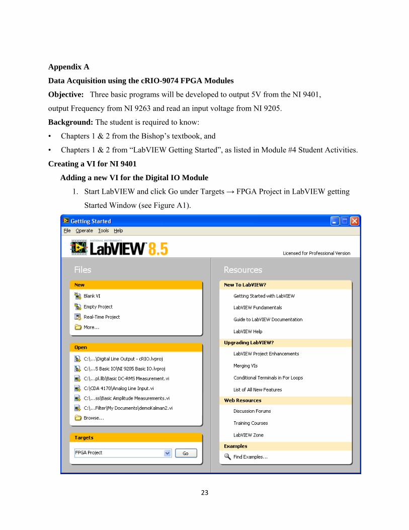
1. Start LabVIEW and click Go under Targets → FPGA Project in LabVIEW getting
Started Window (see Figure A1).
24
Figure A1 LabVIEW Getting Started
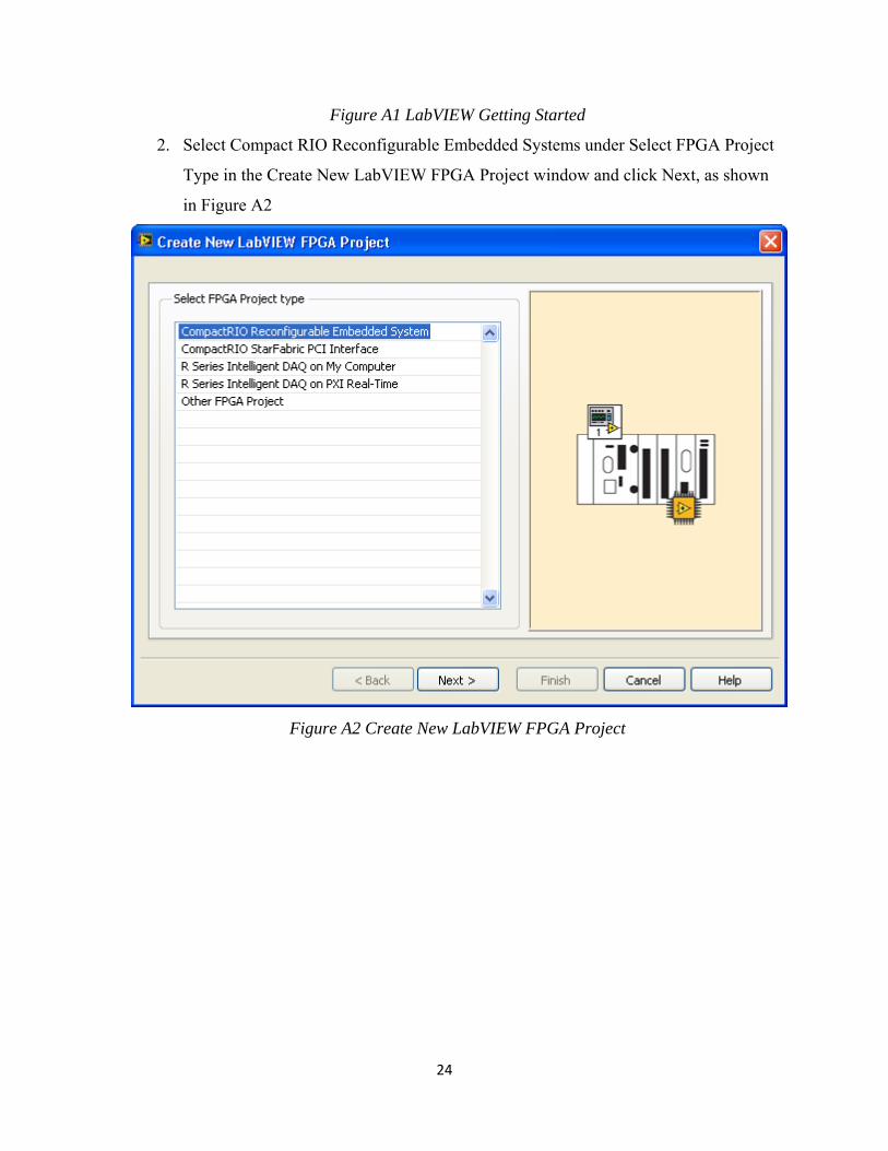
2. Select Compact RIO Reconfigurable Embedded Systems under Select FPGA Project
Type in the Create New LabVIEW FPGA Project window and click Next, as shown
in Figure A2
Figure A2 Create New LabVIEW FPGA Project
25
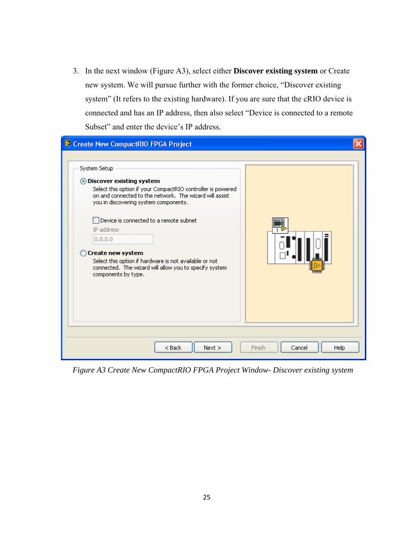
3. In the next window (Figure A3), select either Discover existing system or Create
new system. We will pursue further with the former choice, “Discover existing
system” (It refers to the existing hardware). If you are sure that the cRIO device is
connected and has an IP address, then also select “Device is connected to a remote
Subset” and enter the device’s IP address.
Figure A3 Create New CompactRIO FPGA Project Window- Discover existing system
26
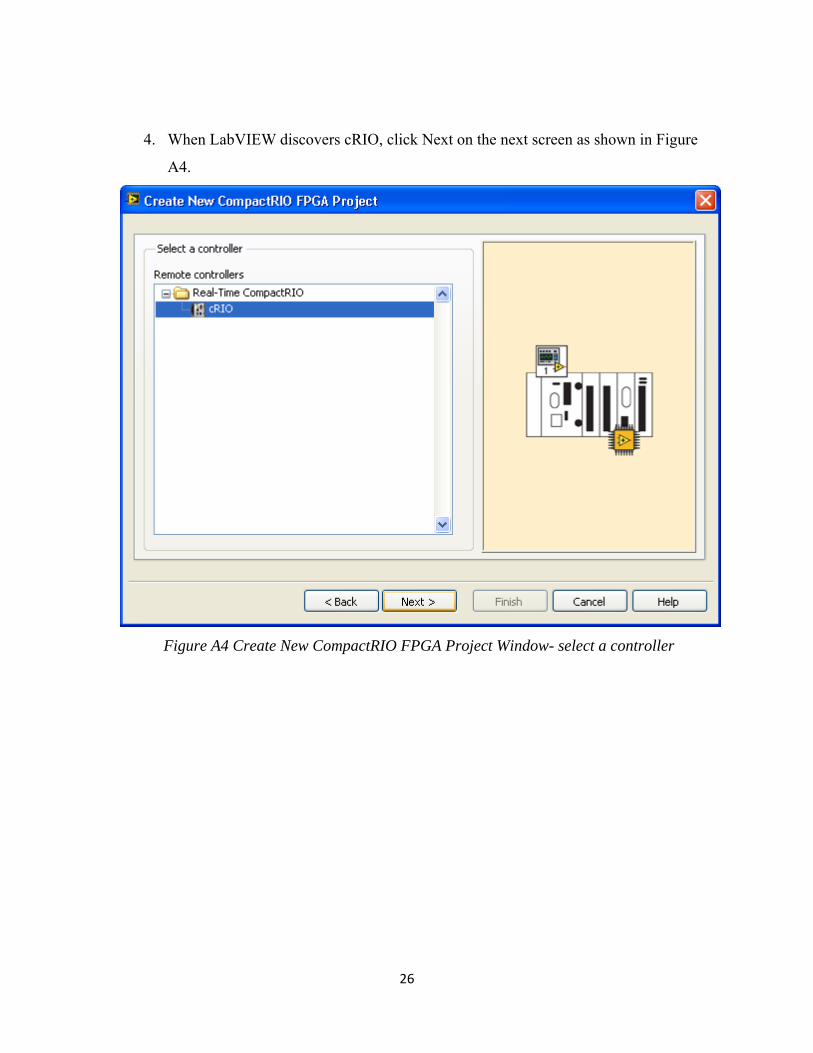
4. When LabVIEW discovers cRIO, click Next on the next screen as shown in Figure
A4.
Figure A4 Create New CompactRIO FPGA Project Window- select a controller
27
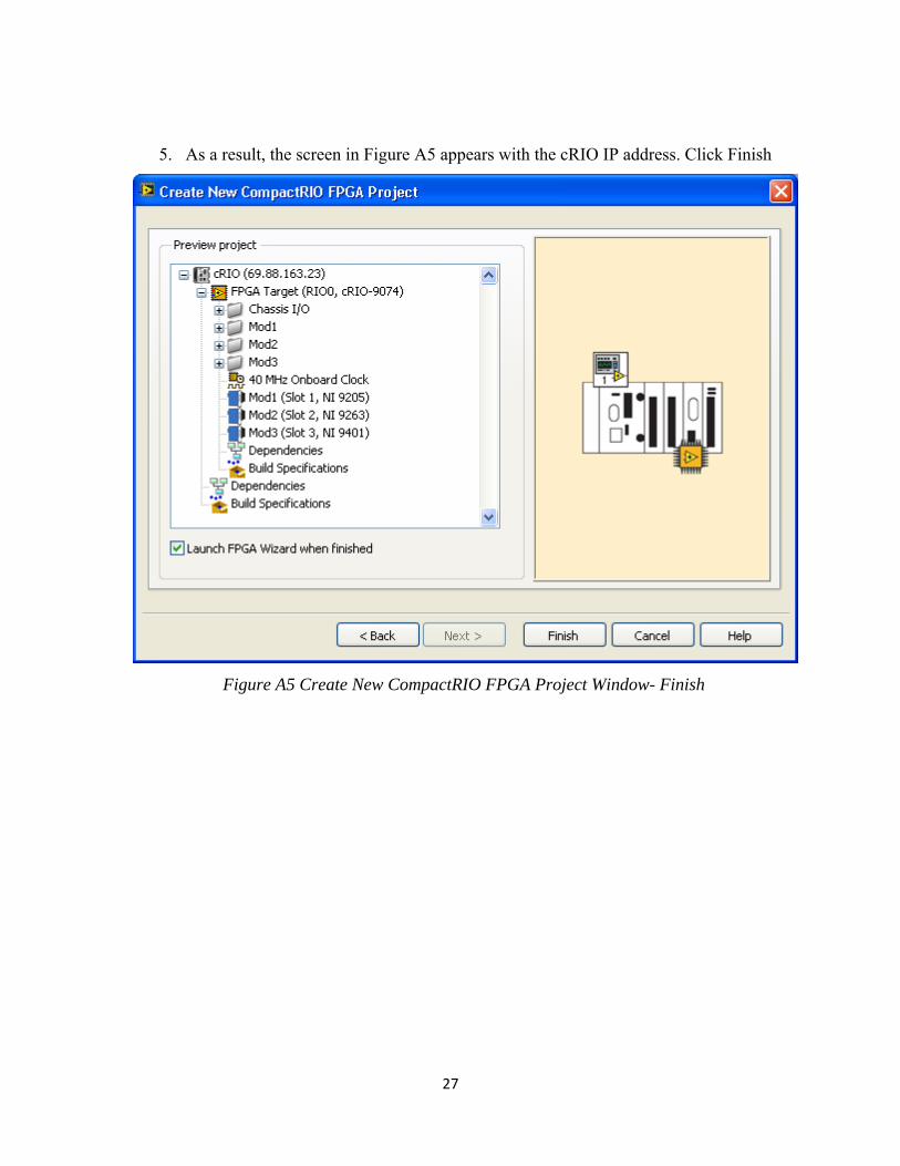
5. As a result, the screen in Figure A5 appears with the cRIO IP address. Click Finish
Figure A5 Create New CompactRIO FPGA Project Window- Finish
28
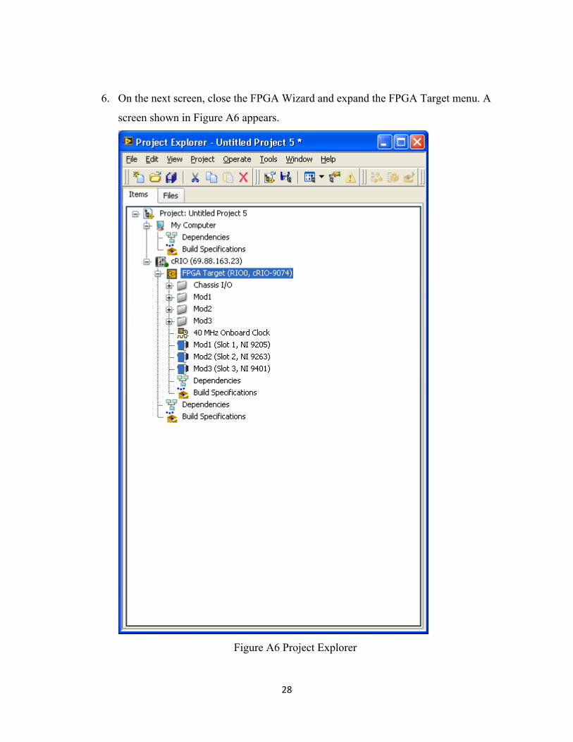
6. On the next screen, close the FPGA Wizard and expand the FPGA Target menu. A
screen shown in Figure A6 appears.
Figure A6 Project Explorer
29
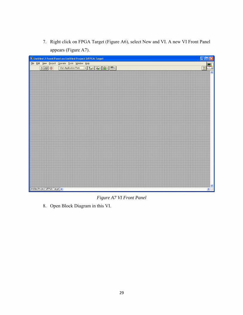
7. Right click on FPGA Target (Figure A6), select New and VI. A new VI Front Panel
appears (Figure A7).
Figure A7 VI Front Panel
8. Open Block Diagram in this VI.
30
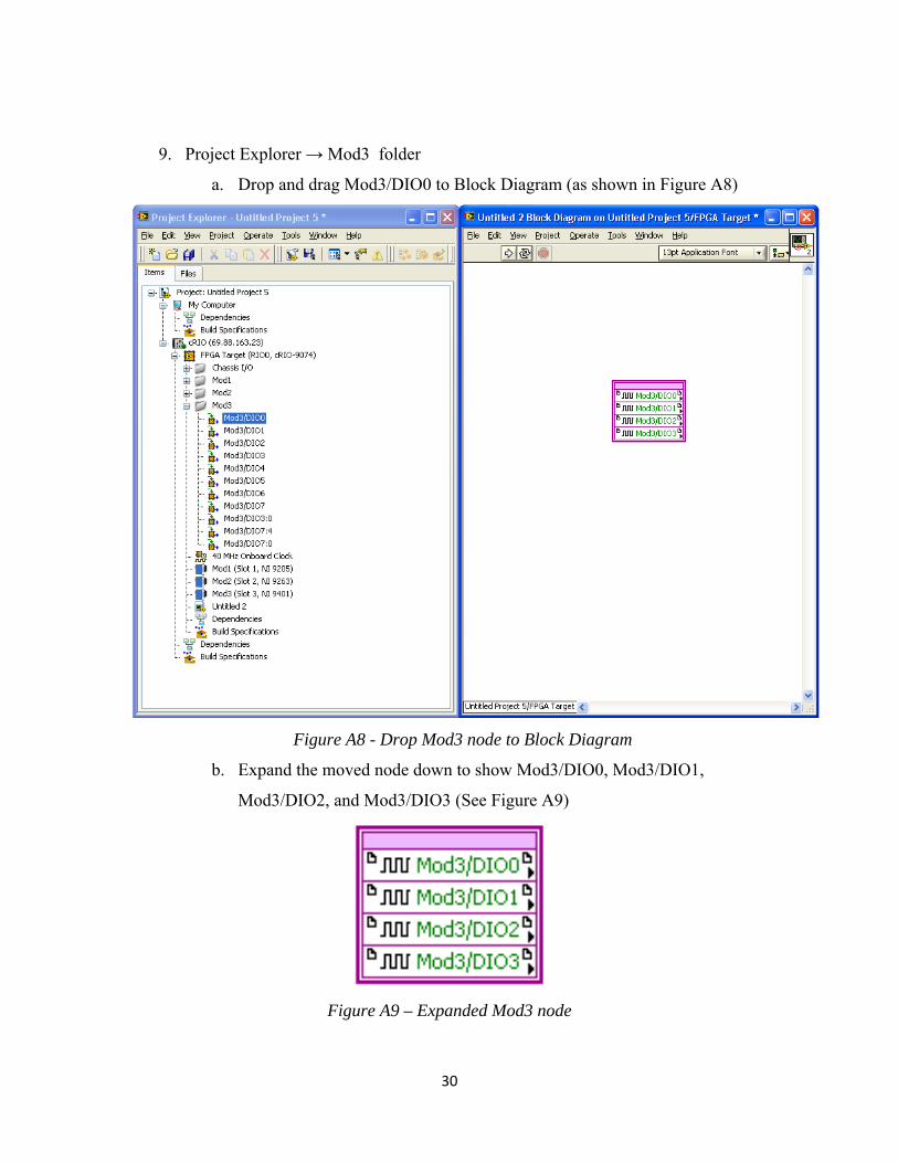
9. Project Explorer → Mod3 folder
a. Drop and drag Mod3/DIO0 to Block Diagram (as shown in Figure A8)
Figure A8 - Drop Mod3 node to Block Diagram
b. Expand the moved node down to show Mod3/DIO0, Mod3/DIO1,
Mod3/DIO2, and Mod3/DIO3 (See Figure A9)
Figure A9 – Expanded Mod3 node
31
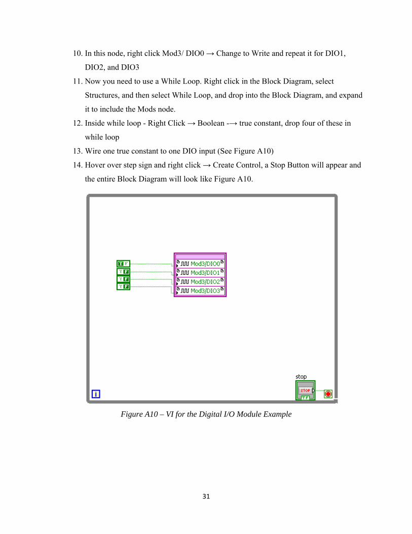
10. In this node, right click Mod3/ DIO0 → Change to Write and repeat it for DIO1,
DIO2, and DIO3
11. Now you need to use a While Loop. Right click in the Block Diagram, select
Structures, and then select While Loop, and drop into the Block Diagram, and expand
it to include the Mods node.
12. Inside while loop - Right Click → Boolean -→ true constant, drop four of these in
while loop
13. Wire one true constant to one DIO input (See Figure A10)
14. Hover over step sign and right click → Create Control, a Stop Button will appear and
the entire Block Diagram will look like Figure A10.
Figure A10 – VI for the Digital I/O Module Example
32
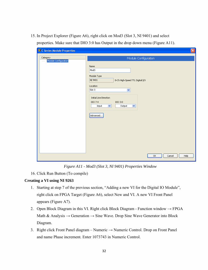
15. In Project Explorer (Figure A6), right click on Mod3 (Slot 3, NI 9401) and select
properties. Make sure that DIO 3:0 has Output in the drop down menu (Figure A11).
Figure A11 - Mod3 (Slot 3, NI 9401) Properties Window
16. Click Run Button (To compile)
Creating a VI using NI 9263
1. Starting at step 7 of the previous section, “Adding a new VI for the Digital IO Module”,
right click on FPGA Target (Figure A6), select New and VI. A new VI Front Panel
appears (Figure A7).
2. Open Block Diagram in this VI. Right click Block Diagram - Function window → FPGA
Math & Analysis → Generation → Sine Wave. Drop Sine Wave Generator into Block
Diagram.
3. Right click Front Panel diagram – Numeric → Numeric Control. Drop on Front Panel
and name Phase increment. Enter 1073743 in Numeric Control.
33
4. Right click on Block Diagram – Programming → Structures → While Loop
5. Hover over stop sign
6. Right click → Create Control (Stop Button)
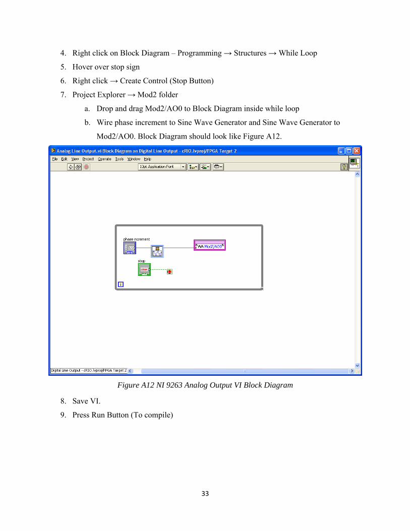
7. Project Explorer → Mod2 folder
a. Drop and drag Mod2/AO0 to Block Diagram inside while loop
b. Wire phase increment to Sine Wave Generator and Sine Wave Generator to
Mod2/AO0. Block Diagram should look like Figure A12.
Figure A12 NI 9263 Analog Output VI Block Diagram
8. Save VI.
9. Press Run Button (To compile)
34
Creating a VI using NI 9205
1. Starting at step 7 of the previous section, “Adding a new VI for the Digital IO Module”,
right click on FPGA Target (Figure A6), select New and VI. A new VI Front Panel
appears (Figure A7).
2. Open Block Diagram in this VI.
3. Project Explorer - Mod 1 folder. Drop and drag Mod1/AI0 to Block Diagram
4. Right Click Mod1/ AI0 → create → indicator
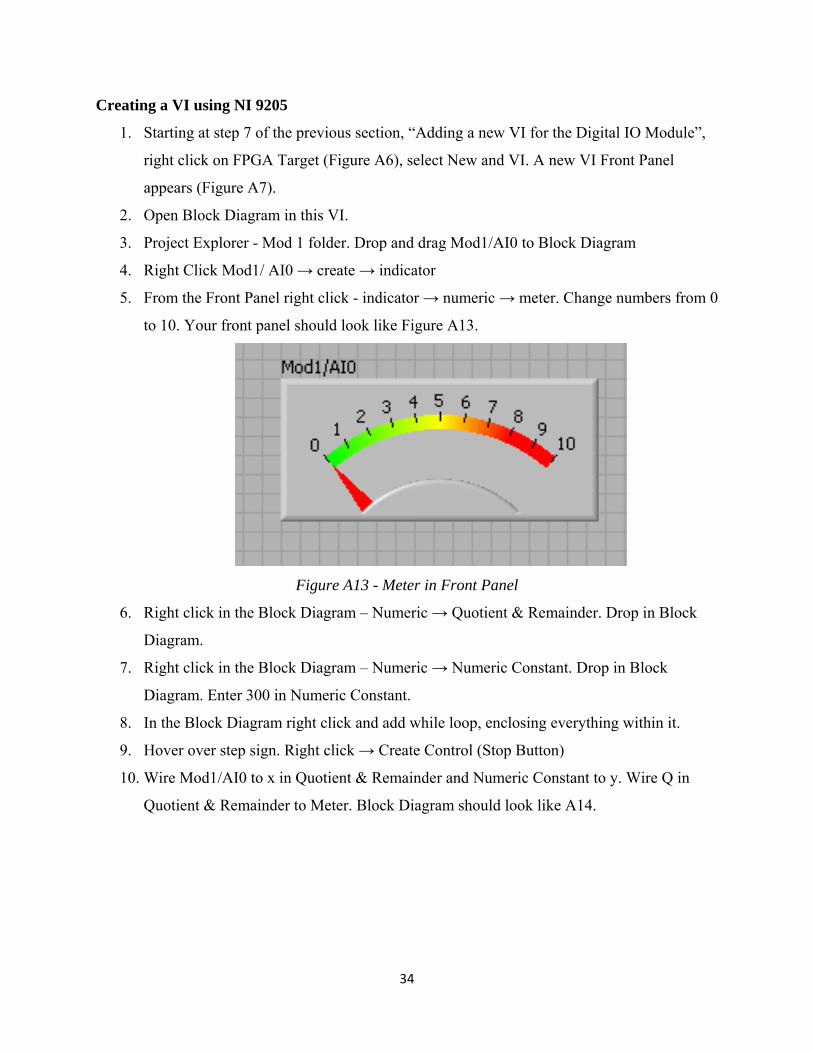
5. From the Front Panel right click - indicator → numeric → meter. Change numbers from 0
to 10. Your front panel should look like Figure A13.
Figure A13 - Meter in Front Panel
6. Right click in the Block Diagram – Numeric → Quotient & Remainder. Drop in Block
Diagram.
7. Right click in the Block Diagram – Numeric → Numeric Constant. Drop in Block
Diagram. Enter 300 in Numeric Constant.
8. In the Block Diagram right click and add while loop, enclosing everything within it.
9. Hover over step sign. Right click → Create Control (Stop Button)
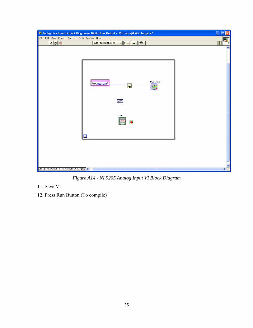
10. Wire Mod1/AI0 to x in Quotient & Remainder and Numeric Constant to y. Wire Q in
Quotient & Remainder to Meter. Block Diagram should look like A14.
35
Figure A14 - NI 9205 Analog Input VI Block Diagram
11. Save VI
12. Press Run Button (To compile)
36
Appendix B
Date: Wed, 1 Apr 2009 15:45:55 ‐0500
From: [email protected]
Reply‐to: [email protected]
Subject: RE: (Reference#1348229) Fw: Problems with cRIO and FPGA
All headers
Note: Your reference number is included in the subject field of this
message. It is very important not to remove or modify this reference
number, or your message may be returned to you.
Hi Joe,
As discussed over the phone today, we will plan to go over the setting of
the cRIO on the phone on Friday, April 3rd at 1pm EST, 12 pm CST.
Please let me know if you will be running late or cannot make it by either
emailing me back or calling in.
Thanks!
Karunya Ravindran
Applications Engineer
National Instruments
http://www.ni.com/support
‐‐‐‐‐‐‐‐‐‐‐‐‐‐‐‐‐‐‐‐‐‐‐‐‐‐‐‐‐‐‐‐‐‐‐‐‐‐‐‐‐‐‐‐‐‐‐‐‐‐‐‐‐‐‐‐‐‐‐‐‐‐‐‐‐‐‐‐‐‐‐‐‐‐‐‐‐‐
Hello Karunya,
Thank you for willing to work with us on this problem over the phone.
We are available tomorrow, Friday, 03/27, beginning 9:30 EST, till
around 1:00pm.
Please let us know your best time to call, maybe two windows, since
37
we'll be busy with the class during this time. Then we'll decide on the
timing who calls whom. (We don't have a telephone in this room, but
can use one of our cell phones.)
Kind Regards,
Janusz
________________________________________
From: [email protected] [[email protected]]
Sent: Wednesday, March 25, 2009 5:27 PM
To: Zalewski, Janusz
Cc: [email protected]; [email protected]; Zalewski, Janusz;
Joanne Sirois
Subject: RE: (Reference#1348229) Fw: Problems with cRIO and FPGA
Note: Your reference number is included in the subject field of this
message. It is very important not to remove or modify this reference
number, or your message may be returned to you.
Hi Jansuz,
It might be easier to troubleshoot this over the phone than over email. If
there is a phone number where I can get in touch with you to troubleshoot
over the phone, please let me know. Or you can get in touch with me at
1‐866‐275‐6964 and reference your service request number. The phone call
will get routed to me and move ahead with this.
38
Thanks!
Karunya Ravindran
Applications Engineer
National Instruments
http://www.ni.com/support
‐‐‐‐‐‐‐‐‐‐‐‐‐‐‐‐‐‐‐‐‐‐‐‐‐‐‐‐‐‐‐‐‐‐‐‐‐‐‐‐‐‐‐‐‐‐‐‐‐‐‐‐‐‐‐‐‐‐‐‐‐‐‐‐‐‐‐‐‐‐‐‐‐‐‐‐‐‐
Hello Karunya,
I will try to answer your questions as much as I can:
> The sofware on the host system isn't as big as a concern as the software
on
> the cRIO itself. Was the cRIO ever working properly.
We never tried to use it for accessing the FPGA or the modules plugged
into the chassis, so it this sense it was never tested. This is the first
attempt.
> How are you connected to the cRIO? Are you using a cross over cable or a
> network switch? If you aren't using a cross over cable, please connect to
> the cRIO using that method.
The cRIO box is connected to the host via the Ethernet, and I don't
think we have the crossover cable. This is how we want to use it:
accessible via the IP address.
> Are you able to install or uninstall any software at all?
39
I think we did. Joanne, could you provide more details?
> Have you tried formatting the cRIO once? Please ensure that you have
access
> to the software on the cRIO before you decide to format the cRIO.
Not sure what you mean by formatting cRIO? Never done that, I think.
Overall, I'd say that we are not going anywhere with this, since
there is too many unknowns to us here. Is there a chance some
National Instruments technician or support person can come here
to check on it?
Thanks and Kind Regards,
Janusz Zalewski
________________________________________
From: [email protected] [[email protected]]
Sent: Friday, March 20, 2009 2:02 PM
To: Joanne Sirois
Cc: [email protected]; Zalewski, Janusz
Subject: Re: (Reference#1348229) Fw: Problems with cRIO and FPGA
Note: Your reference number is included in the subject field of this
message. It is very important not to remove or modify this reference
number, or your message may be returned to you.
40
Hi Joanne,
I just have a few questions on the workings on your cRIO.
The sofware on the host system isn't as big as a concern as the software on
the cRIO itself. Was the cRIO ever working properly.
How are you connected to the cRIO? Are you using a cross over cable or a
network switch? If you aren't using a cross over cable, please connect to
the cRIO using that method.
Are you able to install or uninstall any software at all?
For example, when you select the cRIO in MAX, Right‐click on software,
select Add/Remove software, and select custom insall, does it instantly
disconnect? Does the System State say disconnected when you exit of the the
software window.
I would like to know when exactly the disconnect happens. Using a cross
over cable to connect the cRIO to the host system should eliminate this
problem.
Have you tried formatting the cRIO once? Please ensure that you have access
to the software on the cRIO before you decide to format the cRIO.
Please let me know the results of this.
Karunya Ravindran
Applications Engineer
National Instruments
41
http://www.ni.com/support
‐‐‐‐‐‐‐‐‐‐‐‐‐‐‐‐‐‐‐‐‐‐‐‐‐‐‐‐‐‐‐‐‐‐‐‐‐‐‐‐‐‐‐‐‐‐‐‐‐‐‐‐‐‐‐‐‐‐‐‐‐‐‐‐‐‐‐‐‐‐‐‐‐‐‐‐‐‐
Hello,
When I select add and remove software cRIO disconnects. So I never get the
option for
custom installation.
I did a print screen of the software that is installed and version numbers
of the host
computer. (Attached)
Joanne Sirois
On Wed, 18 Mar 2009 12:40:02 ‐0500, support wrote
> Note: Your reference number is included in the subject field of this
> message. It is very important not to remove or modify this reference
> number, or your message may be returned to you.
>
> Hello Joanne,
>
> Since Karunya is leading a customer training today, I wanted to reply to
> you on her behalf.
>
42
> The Variable Client support does need to be installed on the controller,
> and the version sometimes does matter. I am not sure which version of
> LabVIEW and LV Real‐Time that you have, so I cannot answer this question
> for sure yet. What I suggest that you do, is when you are connected to
> your host computer, open MAX and right‐click Software underneath your
> Remote Systems target, and select Add/Remove Software. Select the option
> for custom isntallation, and ensure that the latest version of the NI‐RIO
> driver and the RT components from your host computer (such as Variable
> Client Support & Variable Engine) are selected for isntallation on the
> CompactRIO.
>
> In case you run into any issues, please let us know, and also tell us
what
> the versions of software on your host computer and target are.
> (Screenshots may be helpful here).
>
> Thanks.
>
> Regards
>
> Kamalina Srikant
43
> Applications Engineer
> National Instruments
>
http://www.ni.com/support
>
>
‐‐‐‐‐‐‐‐‐‐‐‐‐‐‐‐‐‐‐‐‐‐‐‐‐‐‐‐‐‐‐‐‐‐‐‐‐‐‐‐‐‐‐‐‐‐‐‐‐‐‐‐‐‐‐‐‐‐‐‐‐‐‐‐‐‐‐‐‐‐‐‐‐‐‐‐‐‐
>
> Karunya,
>
> Both Variable Client Support and Network variable are installed although
> they are
>
> version 1.4.0 instead of 1.5.0
>
> Would that cause a problem?
>
> Thank you,
>
> Joanne Sirois
44
>
> On Thu, 12 Mar 2009 15:00:55 ‐0500, support wrote
>
> > Note: Your reference number is included in the subject field of this
>
> > message. It is very important not to remove or modify this reference
>
> > number, or your message may be returned to you.
>
> >
>
> > Hi Janusz,
>
> >
>
> > Thank you for getting in touch with support. My name is Karunya
Ravindran
>
> > and I will be helping you with this issue.