Embed Size (px)
Citation preview

Exercise 7.
Four Terminal Electronic Component
Required knowledge
• Calculation of inductance of toroidal and solenoidal inductors.
• Knowledge of basic definitions related to magnetism and magnetic materials, e.g.,
magnetic field strength (H), magnetic flux density (B), permeability, B-H curve,
hysteresis loop, saturation, core loss, copper loss, inductance factor.
• Interpretation of quantities at the end of this guide, and interpretation of any of the
quantities that are mentioned in the laboratory exercises.
• Connection between the current and induced voltage in an inductor. Calculation of H
and B in an inductor. Calculation for sinusoidal excitation.
• Kinds of losses in a transformer/inductor, e.g., copper loss, core loss (hysteresis loss,
eddy current loss). Why laminated cores are used? How the skin effect changes the
copper loss?
• In circuit measurement.
• Parameters and models (equivalent circuit) of transformers, e.g., how core and copper
losses, leakage/magnetizing reactances are modeled, dependency between turn ratio and
secondary/primary voltage and current. Insertion loss.
Aim of the measurement
You will learn how to model impedances and four terminal electrical components. The
measurement is primarily connected to test of materials, parameter identification and in-
circuit measurements.
© BME VIK Students attending the courses of Laboratory 1 (BMEVIMIA304) are allowed to download this file, and to make one printed copy of this guide. Other persons are prohibited to use this guide without the authors' written permission.

Laboratory exercises 1.
6
Measurement instruments
Precision Magnetics Analyzer
Wayne Kerr 3260B
Kelvin Clip Leads
The Front Panel
Main features of the Magnetics Analyzer:
• Frequency range: 20 Hz – 3 MHz
• Drive Level: 1 mV to 10 Vrms into open circuit,
5 µA to 200 mArms into short circuit
• Source Impedance: 50 Ω
© BME VIK Students attending the courses of Laboratory 1 (BMEVIMIA304) are allowed to download this file, and to make one printed copy of this guide. Other persons are prohibited to use this guide without the authors' written permission.

Four terminal electronic components
3
Test board
loose coupling tight coupling tight coupling loose coupling
Ferromagnetic parameter of the DUT
Type: TDK H5A
Core material: ferrite
Core form: toroid
Recommended maximum frequency: 0,2 MHz
Initial permeability, µi : 3300 -0….+40%
Max. flux density , Bm: 410 mT @ H=1194 A/m
Inductivity factor, AL: 4300±25% nH
Core size:
D = 68 mm, d = 44 mm, h = 13,5 mm
Number of primary turns, Np: 110
Number of secondary turns, Ns: 110
Cross section of the copper wire, ACU: 0,05 mm2
Specific resistance of the copper: 1,678*10-8
Ωm
Diameter of isolated wire dw: 0,6 mm
Coupling: loose coupling (Tr-1), tight coupling (Tr-2)
© BME VIK Students attending the courses of Laboratory 1 (BMEVIMIA304) are allowed to download this file, and to make one printed copy of this guide. Other persons are prohibited to use this guide without the authors' written permission.
Laboratory exercises 1.
6
Required knowledge (repetition)
Classifications of Magnetic Materials
When a material is placed within a magnetic field, that shows magnetic properties, but
sometimes the reaction is too weak to notice. Usually the people refer to it as nonmagnetic
material. In fact this is a kind of magnetic behavior, and all matter have magnetic properties.
You can classify the materials their magnetic properties into the following five major group:
diamagnetic, paramagnetic, ferromagnetic, ferrimagnetic, antiferromagnetic. The origin of
magnetism can be explained by the atomic and molecular structure of the material, the orbital
and spin motions of electrons.
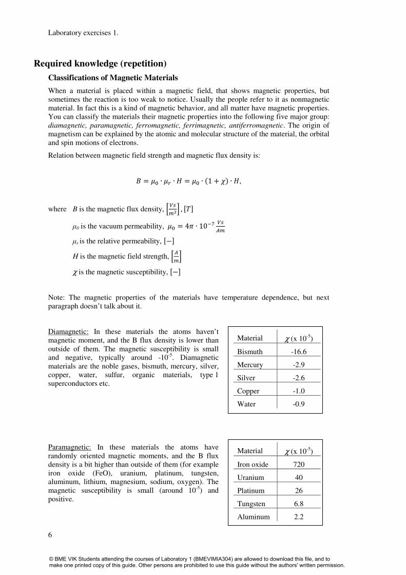
Relation between magnetic field strength and magnetic flux density is:
= ∙ ∙ = ∙ 1 + ∙ ,
where B is the magnetic flux density, , µ0 is the vacuum permeability, = 4 ∙ 10
µr is the relative permeability, − H is the magnetic field strength, χ is the magnetic susceptibility, −
Note: The magnetic properties of the materials have temperature dependence, but next
paragraph doesn’t talk about it.
Diamagnetic: In these materials the atoms haven’t
magnetic moment, and the B flux density is lower than
outside of them. The magnetic susceptibility is small
and negative, typically around -10-5
. Diamagnetic
materials are the noble gases, bismuth, mercury, silver,
copper, water, sulfur, organic materials, type 1
superconductors etc.
Paramagnetic: In these materials the atoms have
randomly oriented magnetic moments, and the B flux
density is a bit higher than outside of them (for example
iron oxide (FeO), uranium, platinum, tungsten,
aluminum, lithium, magnesium, sodium, oxygen). The
magnetic susceptibility is small (around 10-5
) and
positive.
Material χ (x 10-5
)
Bismuth -16.6
Mercury -2.9
Silver -2.6
Copper -1.0
Water -0.9
Material χ (x 10-5
)
Iron oxide 720
Uranium 40
Platinum 26
Tungsten 6.8
Aluminum 2.2
© BME VIK Students attending the courses of Laboratory 1 (BMEVIMIA304) are allowed to download this file, and to make one printed copy of this guide. Other persons are prohibited to use this guide without the authors' written permission.

Four terminal electronic components
5
Ferromagnetic: In these materials the atoms are arranged into domains, and the domains have
parallel aligned magnetic moments. The B flux density is much higher (101…10
6) than
outside of them, and it depends on the applied H magnetic field strength (hysteresis loop),
the domain size and domain structure.
The ferromagnetic materials can be grouped into three subgroup:
1. Ferromagnetic base metals: iron, nickel cobalt.
2. Ferromagnetic alloys:
a. It contains ferromagnetic base metals
b. Heusler alloy: It doesn’t contain ferromagnetic base metals
3. Ferrite: ferromagnetic base metals (or its oxide) + oxide of the other metals.
There are five different regions on the virgin (and the hysteresis) curve:
Note: there aren’t sharp borders between these regions
1. Linear ( or initial ) region: = ∙ ∙
2. Square (or Rayleigh) region: = ∙ ∙ + ∙ !, = Rayleigh hysteresis constant
3. Maximum permeability region: "## = $%&
∙ "'"( 4. Saturation region: see the figure
5. Paramagnetic region: "## = ")"( ≈ 0.01
© BME VIK Students attending the courses of Laboratory 1 (BMEVIMIA304) are allowed to download this file, and to make one printed copy of this guide. Other persons are prohibited to use this guide without the authors' written permission.

Laboratory exercises 1.
6
The measuring of the initial permeability is difficult.
= 1 ∙ lim(→
Some materials at weak (H0) magnetizing force can behave as paramagnetic way. In this
case the domains can’t sense the external force. It looks like the domains are “frozen in”.
That’s why the initial permeability is measured at 4 mA/cm. This value is enough big to
“melt out” the domains, but it’s enough small to the magnetizing force stays in the initial
region.
Transformer:
Mutual flux: this flux is inside
in the core (flux is closed
through both windings).
Leakage flux: this flux is
outside of the windings (flux
is closed through only one
windings, there is no coupling
between windings).
The mutual inductance
between two coils is:
0 = 12$ ∙ 2!
Quality factor (Q):
series
series
R
LQ
ω=
© BME VIK Students attending the courses of Laboratory 1 (BMEVIMIA304) are allowed to download this file, and to make one printed copy of this guide. Other persons are prohibited to use this guide without the authors' written permission.

Four terminal electronic components
7
Coupling factor (k):
The definition of coupling factor is:
3 = )145∙4
Note: coupling between the two coils
can never reach or exceed 1.
less parasitic capacitance
higher leakage inductance
higher dielectric strength
For example: High Voltage application
higher parasitic capacitance
less leakage inductance
less dielectric strength
For example: telecommunication
Ferrimagnetic: In these materials the atoms have mixed
parallel and anti-parallel aligned magnetic moments.
The magnetic susceptibility is large.
Antiferromagnetic: In these materials the atoms have
anti-parallel aligned magnetic moments. The magnetic
susceptibility is positive and small.
k = 0 no inductive coupling
0 < k < 0.5 loosely coupled
k = 0.5
0.5 < k < 1 tightly coupled
k = 1 full or maximum inductive coupling
© BME VIK Students attending the courses of Laboratory 1 (BMEVIMIA304) are allowed to download this file, and to make one printed copy of this guide. Other persons are prohibited to use this guide without the authors' written permission.

Laboratory exercises 1.
6
Calculation of inductance of toroidal inductor:
2 = ∙ ∙ 67 ∙ 8!
= 4 ∙ 10 9:6;
where,
L = self-inductance of coil with core [H]
= permeability of vacuum
= relative permeability
A = cross-sectional area of toroidal core (mm2)
l = average length of magnetic path in the core
[mm]
N = number of turns
In the datasheet of torodial ferrite you can find the so
called inductance coefficient Al. It’s defined as the
self-inductance per unit turn of a coil of a given shape
and dimensions wound on a magnetic core. Al allows
us to simply calculate the inductance by multiplying it
with the square of the number of turns as the formulas
on the right show.
7 = <="! ∙ , 6 = <"
! ∙ ℎ
6? = ∙ ∙ ? , 2 = 6? ∙ 8!
Measurement Tasks0.
1. Trimming The purpose of trimming is to eliminate the effects of stray capacitance or series impedance
in the connecting leads or fixture. For O/C (Open Circuit) Trim the Kelvin clips or fixture
jaws should be separated by a distance equivalent to the DUT pin separation. For S/C (Short
Circuit) Trim the connector jaws should be clipped to a piece of wire or a component lead as
close together as possible. Do not connect the clips directly together: this does not provide
the necessary 4-terminal short circuit and will lead to trim errors. The trimming requires
some minutes.
Connections for O/C
trimming of Kelvin clips
Connections for S/C
trimming of Kelvin clips
© BME VIK Students attending the courses of Laboratory 1 (BMEVIMIA304) are allowed to download this file, and to make one printed copy of this guide. Other persons are prohibited to use this guide without the authors' written permission.
Four terminal electronic components
9
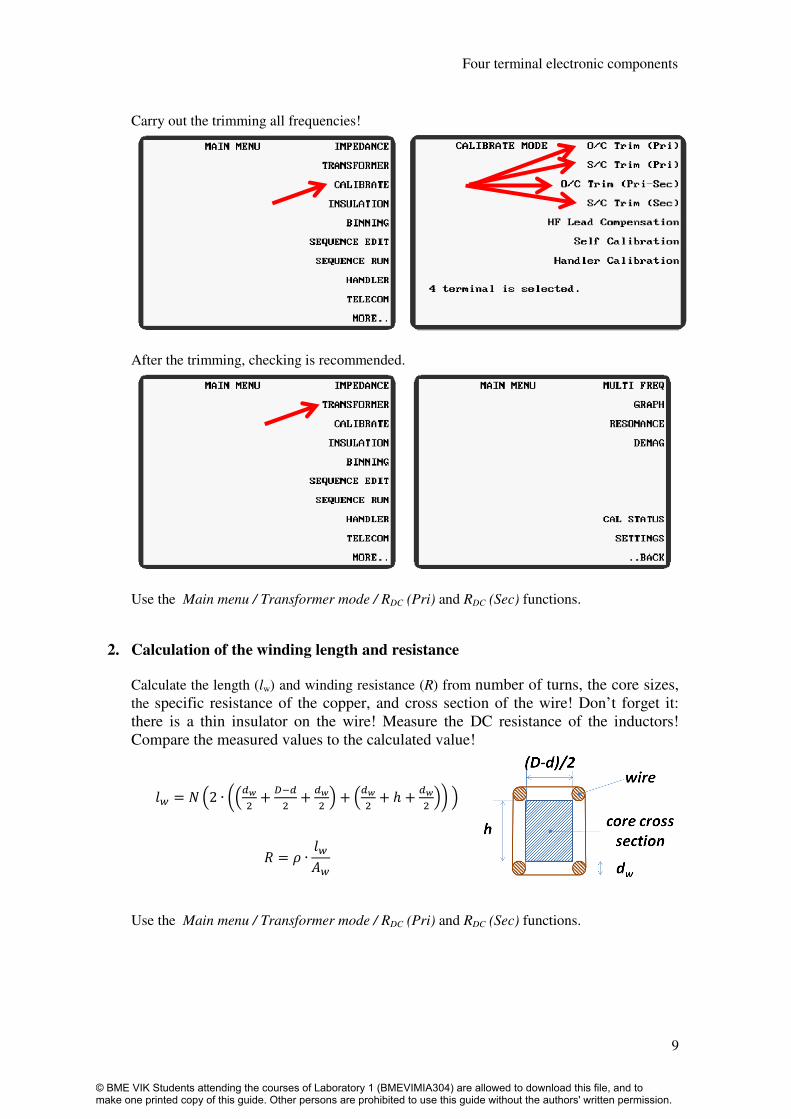
Carry out the trimming all frequencies!
After the trimming, checking is recommended.
Use the Main menu / Transformer mode / RDC (Pri) and RDC (Sec) functions.
2. Calculation of the winding length and resistance
Calculate the length (lw) and winding resistance (R) from number of turns, the core sizes,
the specific resistance of the copper, and cross section of the wire! Don’t forget it:
there is a thin insulator on the wire! Measure the DC resistance of the inductors!
Compare the measured values to the calculated value!
7@ = 8A2 ∙ CA"D! + <"
! + "D! E + A"D
! + ℎ + "D! EFE
G = H ∙ 7@6@
Use the Main menu / Transformer mode / RDC (Pri) and RDC (Sec) functions.
© BME VIK Students attending the courses of Laboratory 1 (BMEVIMIA304) are allowed to download this file, and to make one printed copy of this guide. Other persons are prohibited to use this guide without the authors' written permission.

Laboratory exercises 1.
6
3. Demagnetization
Before the magnetic measurement, a demagnetization procedure is recommended. You can
reach this ability of Analyzer on the second page in main menu.
Set up these parameters, and press the Start key.
Now, the ferrite core is demagnetized.
4. Initial permeability determination by impedance measurement
4.1. Measure the coil impedance at 1V in the range of 100 Hz…500 kHz!
Technical terminology: coil = real inductor
Set the next parameters in the proper menu:
Main menu / Impedance: Drive current 1mAAC, ALC function OFF, speed Medium
Main menu / next / graph mode: Log (Hz), Log(Z)
© BME VIK Students attending the courses of Laboratory 1 (BMEVIMIA304) are allowed to download this file, and to make one printed copy of this guide. Other persons are prohibited to use this guide without the authors' written permission.

Four terminal electronic components
11
All coils have some small real resistance, and parasitic capacitance exists between turns of
the coil.
4.2. Measure the resonance frequency and the self-capacitance of the coil!
Try out the cursors, peak search function to find the resonant frequency. Use the resonance finding function of the analyzer. Main menu / Resonance mode/ Find parallel.
4.3. What is the max. measurement frequency if the systematic error caused by the resonance is not higher than 1%?
4.4. Measure the coil impedance at 150 Hz in the range of 1 mV…10 V using the Graph-mode of the Analyzer!
The next equation can work well in the case of small magnetizing force (H0).
= ∙ ∙ , =
See the hysteresis curve: if there is no magnetic field, there is no magnetization and you begin at the origin. (You have done the demagnetization.) If you increase the magnetizing force the permeability will change. It is shown in the figure on page 4 by dashed curve. The first magnetization curve is the virgin curve.
There is non-linear relation between B and H, µr depends on H.
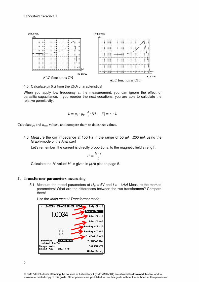
You can see this effect on the impedance vs. low frequency AC level diagram.
Set the proper parameters in Impedance and Graph menu.
© BME VIK Students attending the courses of Laboratory 1 (BMEVIMIA304) are allowed to download this file, and to make one printed copy of this guide. Other persons are prohibited to use this guide without the authors' written permission.
Laboratory exercises 1.
6
ALC function is ON
ALC function is OFF
4.5. Calculate µr(Bm) from the Z(U) characteristics!
When you apply low frequency at the measurement, you can ignore the effect of parasitic capacitance. If you reorder the next equations, you are able to calculate the relative permittivity:
2 = ∙ ∙ ? ∙ 8! , |J| = K ∙ 2
Calculate µi and µmax values, and compare them to datasheet values.
4.6. Measure the coil impedance at 150 Hz in the range of 50 µA…200 mA using the Graph-mode of the Analyzer!
Let’s remember: the current is directly proportional to the magnetic field strength.
= 8 ∙ L7
Calculate the H* value! H* is given in µ(H) plot on page 5.
5. Transformer parameters measuring
5.1. Measure the model parameters at Ueff = 5V and f = 1 kHz! Measure the marked parameters! What are the differences between the two transformers? Compare them!
Use the Main menu / Transformer mode
© BME VIK Students attending the courses of Laboratory 1 (BMEVIMIA304) are allowed to download this file, and to make one printed copy of this guide. Other persons are prohibited to use this guide without the authors' written permission.

Four terminal electronic components
13
6. In-circuit measurement on RC-network
Technical data of the RC-components:
R1 = 100 Ω ±0,1%
R2 = R4 = 1 kΩ ±1%
R5 = 10 kΩ ±2%
C1 = 1 µF ±5%
C2 = 100 nF ±5%
R4 R5
IN R1 R2 OUT
C1 C2
Figure 7–1. Schematic of low-pass filter to be measured
6.1. Measure all of the RC components using in-circuit technique! Are the measured values within the specified tolerance bands?
© BME VIK Students attending the courses of Laboratory 1 (BMEVIMIA304) are allowed to download this file, and to make one printed copy of this guide. Other persons are prohibited to use this guide without the authors' written permission.

Last modified: 2013.11.15. 13:09:00, rev.: 19 14
Some quantities related to magnetic materials
Notation Name Unit Calculation
I, I Current, excitation current A (mA)
N Number of turns 1
Θ Magnetic excitation A (mA) Θ = NI
l Average length of magnetic field m (cm) for a closed core.
H, H Strength of magnetic field A/m (A/cm, mA/cm) H = Θ/l = NI/l H = ReH + jImH
Hm Maximum strength of magnetic field A/m (A/cm, mA/cm) Hm = √2 H for sinusoidal H
B, B Magnetic flux density T, Wb/m2 (mT) B = µ0 µr H B = µ0 µr H B = ReB + jImB
Bm Maximum of magnetic flux density T, Wb/m2 (mT) Bm = √2 B for sinusoidal B
µ Absolute permeability V·s/A·m µ = B/H = µ0 µr
µ0 Permeability of vacuum V·s/A·m 4π·10-7
.
µr Relative permeability 1 µr = µ / µ0 = µ0-1
B/H can be a nonlinear function, i.e., µr = µr(H)
µa Amplitude permeability 1 µa = µ0-1
Bm /Hm for variable excitation, Hdc=0.
µ Relative complex permeability 1 µ = µ'-j µ" describes phase shift between B and H in non-ideal circumstances.
µ' Real value of relative complex
permeability
1 µ' = Re µ
- µ" Imaginary value of relative complex
permeability
1 - µ" = Im µ
|µ| Absolute value of relative complex
permeability
1 |µ| = sqrt ( µ'2 + µ"
2 )
µi Relative initial permeability 1 µi = µa= µ0-1
Bm /Hm at limiting case Bm, Hm →0
µ4 Initial permeability @ Hm= 4 mA/cm 1 µ4 = µa= µ0-1
Bm /Hm measured at Hm= 4 mA/cm by definition
µmax Relative maximal permeability 1 peak value of curves µr (H) or µr (B)
µ e Relative effective permeability 1 kind of equivalent permeability of a core that has, e.g, irregular shape, mixed
material, air gap or any non-ideal properties.
A Cross section area of core m2 (cm
2) Note: it can be less than the physical cross-section, e.g., laminated core
Φ Magnetic flux Wb, V·s Φ = BA
L Inductivity H, Wb/A L = NΦ /I L= µ0 µr N 2A/l = 10
-9N
2AL
AL Inductance factor, AL nH AL = 109 µ0 µr A/l (inductivity can be calculated as L = 10
-9N
2AL, see above)
Zs Serial impedance of an inductance Ω, V/A Zs = Rs+jωLs = jω µ0 (µ'-j µ")N 2A/l, Ls = µ0 µ'N
2A/l Rs = ω µ0 µ"N
2A/l
|Zs| = sqrt (Rs2+ω
2Ls
2) = ω µ0 |µ| N
2A/l
Q Quality factor 1 Q = ωLs /Rs = µ'/µ"
tgδ Tangent of loss angle 1 tgδ =1/Q = µ"/µ'
Zs' Corrigated serial impedance Ω, V/A Zs' = Rv +jωLs = jω µ0 (µ'-j µ")N 2A/l, Ls = µ0 µ'N
2A/l Rv = ω µ0 µ"N
2A/l
|Zs'| = sqrt (Rv2+ω
2Ls
2) = ω µ0 |µ|N
2A/l, Rv=Rs-RCu
5
Four term
inal electro
nic co
mponen
ts
© BME VIK Students attending the courses of Laboratory 1 (BMEVIMIA304) are allowed to download this file, and to make one printed copy of this guide. Other persons are prohibited to use this guide without the authors' written permission.
Exercise 7. Four Terminal Electronic Component
15
Last modified: 2013.11.15. 13:09:00, rev.: 19
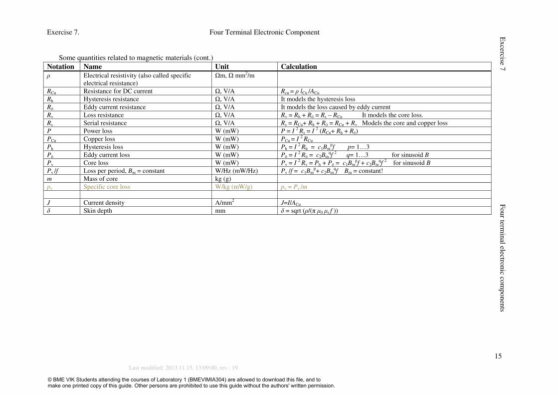
Some quantities related to magnetic materials (cont.)
Notation Name Unit Calculation
ρ Electrical resistivity (also called specific
electrical resistance)
Ωm, Ω mm2/m
RCu Resistance for DC current Ω, V/A Rcu = ρ lCu /ACu
Rh Hysteresis resistance Ω, V/A It models the hysteresis loss
Rö Eddy current resistance Ω, V/A It models the loss caused by eddy current
Rv Loss resistance Ω, V/A Rv = Rh + Rö = Rs – RCu It models the core loss.
Rs Serial resistance Ω, V/A Rs = RCu+ Rh + Rö = RCu + Rv Models the core and copper loss
P Power loss W (mW) P = I 2 Rs = I
2 (RCu+ Rh + Rö)
PCu Copper loss W (mW) PCu = I 2 RCu
Ph Hysteresis loss W (mW) Ph = I 2 Rh = c1Bm
pf p= 1…3
Pö Eddy current loss W (mW) Pö = I 2 Rö = c2Bm
qf
2 q= 1…3 for sinusoid B
Pv Core loss W (mW) Pv = I 2 Rv = Ph + Pö = c1Bm
pf + c2Bm
qf
2 for sinusoid B
Pv /f Loss per period, Bm = constant W/Hz (mW/Hz) Pv /f = c1Bmp+ c2Bm
qf Bm = constant!
m Mass of core kg (g)
pv Specific core loss W/kg (mW/g) pv = Pv /m
J Current density A/mm2 J=I/ACu
δ Skin depth mm δ = sqrt (ρ/(π µ0 µr f ))
Excercise 7
Four term
inal electro
nic co
mponen
ts
© BME VIK Students attending the courses of Laboratory 1 (BMEVIMIA304) are allowed to download this file, and to make one printed copy of this guide. Other persons are prohibited to use this guide without the authors' written permission.

Last modified: 2013.11.15. 13:09:00, rev.: 19 16
© BME VIK Students attending the courses of Laboratory 1 (BMEVIMIA304) are allowed to download this file, and to make one printed copy of this guide. Other persons are prohibited to use this guide without the authors' written permission.