Embed Size (px)
Citation preview
Foundation for rollerpress in a cement plantA case study
J.D. Buch
The paper describes roller press structure in a cement mill ofa cement plant. When provision of press is planned along withmill building, it is possible to provide suitable structuralarrangement. This provision is sometimes made in an existingmill or in mill structure already under construction. In sucha case, limitations are imposed on planning of supportingstructure. Since the introduction of press is a new develop-ment, there is still a lack of reliable machine load data andvibration constraints. A case study of such a foundation inrecently-constructed cement plant is given with recommen-dations on proposed structural arrangement.
A roller press is installed in front of grinding installations tocut down energy consumption in the grinding unit. Installa-tion of a roller press before rolling mill or cement mill incement plants is now becoming a common feature.
In a roller press, clinker material is subjected to extremepressure between opposing rollers for a short time, Fig 1. Oneroller is fixed and other roller can move by about 50 mmlaterally (perpendicular to rotating axis) to adjust space for sizeof material to be rolled between the rollers. This movement isachieved by hydraulic/pneumatic supporting system andkeeps roller gap or pressure constant. Each roller is driven byan electric motor through a gear reducer. The products dis-charged from roller press are compacted cakes of irregularsize.
Case studyIn a certain cement plant, it was decided to provide a rollerpress after column and mill foundations of a cement mill were
J. D. Buch, M.S.E. (USA), B.E. (Hons.), F.I.E., Engineering Associate with Fig 1 Roller press in a cement plant where clinker is ground underKothari and Associates, G-65, Connaught Circus, New Delhi 110 001. high pressure
October 1992 * The Indian Concrete Journal
559
.96 0 0
Roller— press
millCement
Pozzolona Clinker
.18 500
.16500
.1 5 0 00
t of press
81 5 k N
9800
.2610
0.00
Sec iron
. 23 500
«21900
11 500
13500
'2,I
800 1345
In
- - —
2540 5235
(400 x 600).. 400
_o 1r 0"--- o
I 120 x 1 20 4 ---- .4-4
, through x II pockets 81 II I I°.I (10 Nos.) 25 I (880 x 650) I?, g
7
1
t of milland roller Ipress
1I I — L —=r1I1= I
o,..,0 .0-11 M
I1
=UM i,,, .
o
---,
L - - -311111==. .toI 1
260
I-
(830 x 650) !
12501,1050i1050 1490iI
TT
n11,1o 0
rl— 260 "'
.(400 x 600) fig 0 -- - 0._
.
— t of roller press
-r--I
I
0Qco
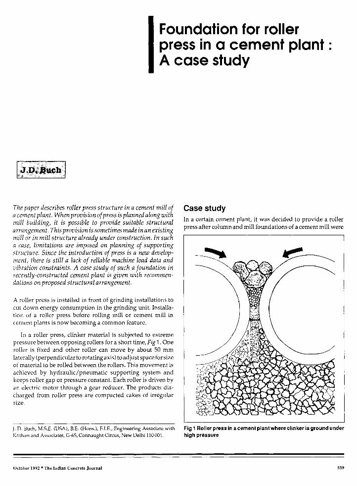
Fig 2 General arrangement under mill hopper area at +9.8 m level(case study)
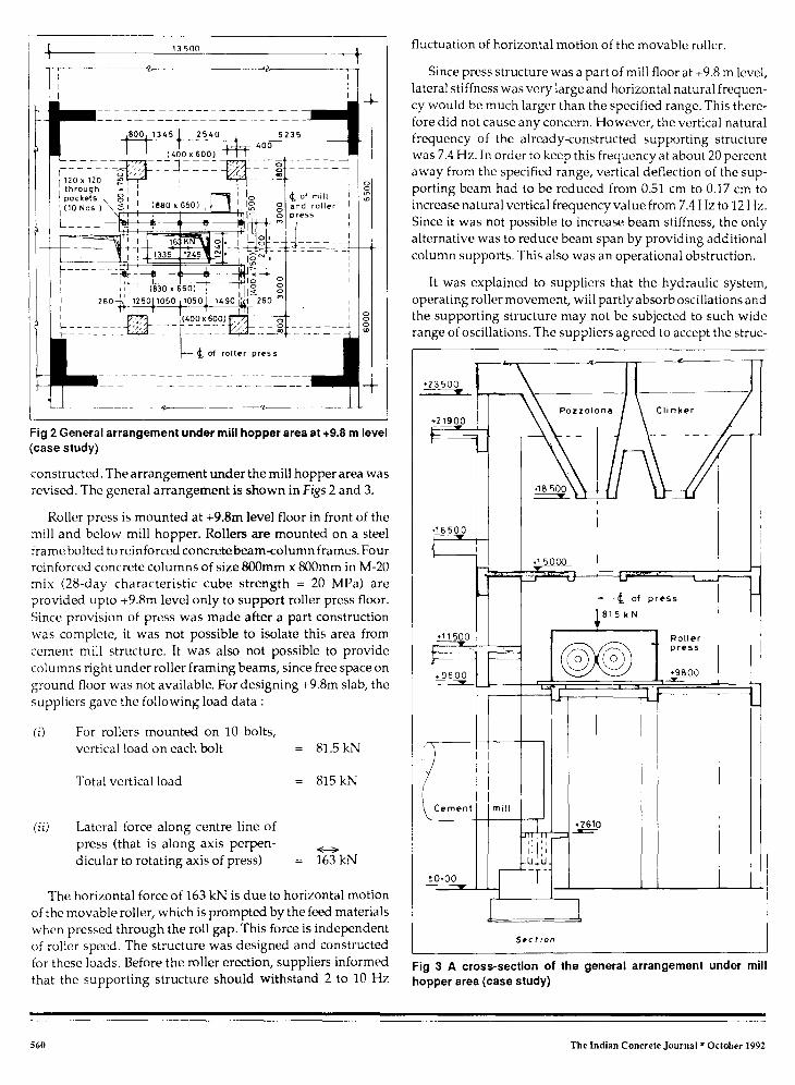
constructed. The arrangement under the mill hopper area wasrevised. The general arrangement is shown in Figs 2 and 3.
Roller press is mounted at +9.8m level floor in front of themill and below mill hopper. Rollers are mounted on a steelframe bolted to reinforced concrete beam-column frames. Fourreinforced concrete columns of size 800mm x 800mm in M-20mix (28-day characteristic cube strength = 20 MPa) areprovided upto +9.8m level only to support roller press floor.Since provision of press was made after a part constructionwas complete, it was not possible to isolate this area fromcement mill structure. It was also not possible to providecolumns right under roller framing beams, since free space onground floor was not available. For designing +9.8m slab, thesuppliers gave the following load data :
For rollers mounted on 10 bolts,vertical load on each bolt = 81.5 kN
Total vertical load = 815 kN
Lateral force along centre line ofpress (that is along axis perpen-dicular to rotating axis of press) = 163 kN
The horizontal force of 163 kN is due to horizontal motionof the movable roller, which is prompted by the feed materialswhen pressed through the roll gap. This force is independentof roller speed. The structure was designed and constructedfor these loads. Before the roller erection, suppliers informedthat the supporting structure should withstand 2 to 10 Hz
fluctuation of horizontal motion of the movable roller.
Since press structure was a part of mill floor at +9.8 m level,lateral stiffness was very large and horizontal natural frequen-cy would be much larger than the specified range. This there-fore did not cause any concern. However, the vertical naturalfrequency of the already-constructed supporting structurewas 7.4 Hz. In order to keep this frequency at about 20 percentaway from the specified range, vertical deflection of the sup-porting beam had to be reduced from 0.51 cm to 0.17 cm toincrease natural vertical frequency value from 7.4 Hz to 12 Hz.Since it was not possible to increase beam stiffness, the onlyalternative was to reduce beam span by providing additionalcolumn supports. This also was an operational obstruction.
It was explained to suppliers that the hydraulic system,operating roller movement, will partly absorb oscillations andthe supporting structure may not be subjected to such widerange of oscillations. The suppliers agreed to accept the struc-
Fig 3 A cross-section of the general arrangement under millhopper area (case study)
560 The Indian Concrete Journal * October 1992
4 Nos120x120x503 deep
— 6 Nos120 x170throughpocket
5000 5000
(t_ of roller press
(750 x 850)
1490 1050 1050 1300
00
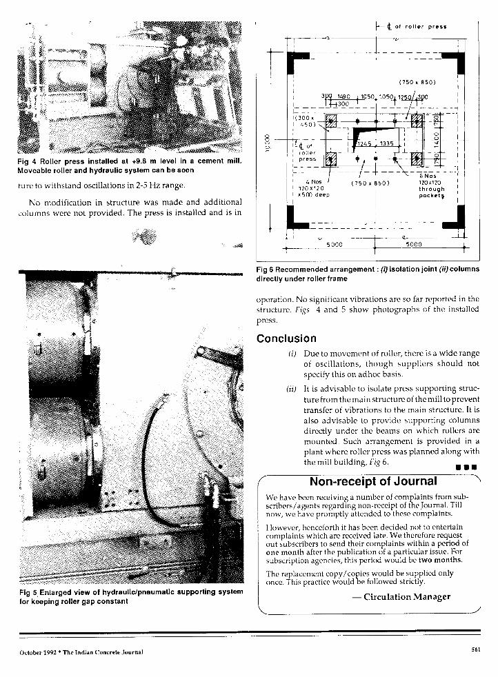
Fig 4 Roller press installed at +9.8 m level in a cement mill.Moveable roller and hydraulic system can be seen
ture to withstand oscillations in 2-5 Hz range.
No modification in structure was made and additionalcolumns were not provided. The press is installed and is in
Fig 5 Enlarged view of hydraulic/pneumatic supporting systemfor keeping roller gap constant
Fig 6 Recommended arrangement : (I) isolation joint (ii) columnsdirectly under roller frame
operation. No significant vibrations are so far reported in the
structure. Figs 4 and 5 show photographs of the installed
press.
ConclusionDue to movement of roller, there is a wide range
of oscillations, though suppliers should not
specify this on adhoc basis.
It is advisable to isolate press supporting struc-
ture from the main structure of the mill to prevent
transfer of vibrations to the main structure. It is
also advisable to provide supporting columns
directly under the beams on which rollers are
mounted. Such arrangement is provided in a
plant where roller press was planned along with
the mill building, Fig 6.• • •
1 Non-receipt of JournalWe have been receiving a number of complaints from sub-scribers/agents regarding non-receipt of the Journal. Tillnow, we have promptly attended to these complaints.
However, henceforth it has been decided not to entertaincomplaints which are received late. We therefore requestout subscribers to send their complaints within a period ofone month after the publication of a particular issue. Forsubscription agencies, this period would be two months.
The replacement copy/copies would be supplied onlyonce. This practice would be followed strictly.
— Circulation Manager
October 1992 n The Indian Concrete Journal 561