Embed Size (px)
Citation preview
1
Foundation Fieldbus
at GNFC
End User Perspective
By: GNFC TDI-II, Dahej
Represented by
C. H. Parmar & H. K. Jinwala
�FF Architecture @ TDI-II
�FF installation @TDI-II
�Design Criteria for TDI-II
� Implementation @ TDI-II
�Installation & commissioning Problems
2
List of contents
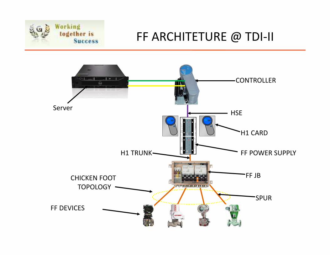
FF ARCHITETURE @ TDI-II
ServerHSE
H1 CARD
FF POWER SUPPLY
FF JBCHICKEN FOOT
TOPOLOGY
FF DEVICES
CONTROLLER
H1 TRUNK
SPUR
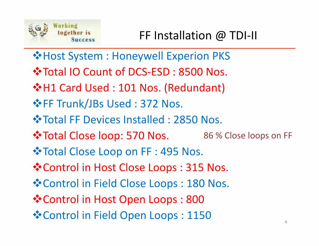
FF Installation @ TDI-II
�Host System : Honeywell Experion PKS
�Total IO Count of DCS-ESD : 8500 Nos.
�H1 Card Used : 101 Nos. (Redundant)
�FF Trunk/JBs Used : 372 Nos.
�Total FF Devices Installed : 2850 Nos.
�Total Close loop: 570 Nos.
�Total Close Loop on FF : 495 Nos.
�Control in Host Close Loops : 315 Nos.
�Control in Field Close Loops : 180 Nos.
�Control in Host Open Loops : 800
�Control in Field Open Loops : 11504
86 % Close loops on FF
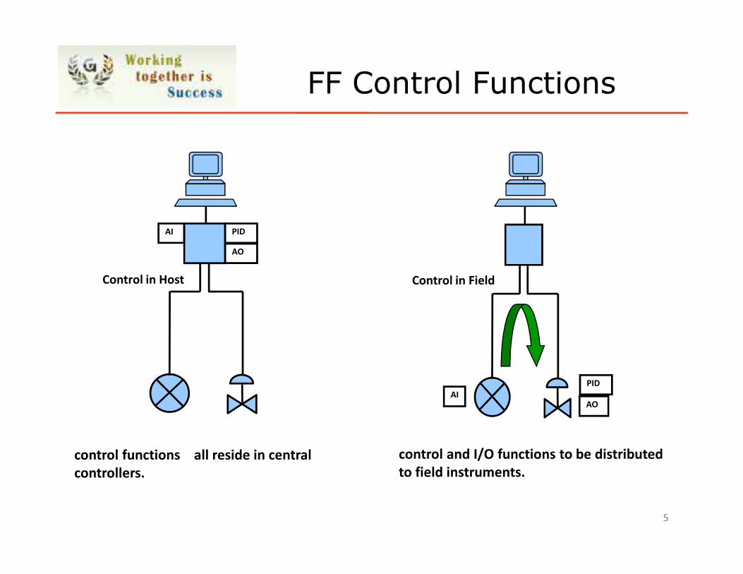
FF Control Functions
Control in Host
PID
AO
AI
control functions all reside in central
controllers.
Control in Field
AOAI
control and I/O functions to be distributed
to field instruments.
5
PID
6
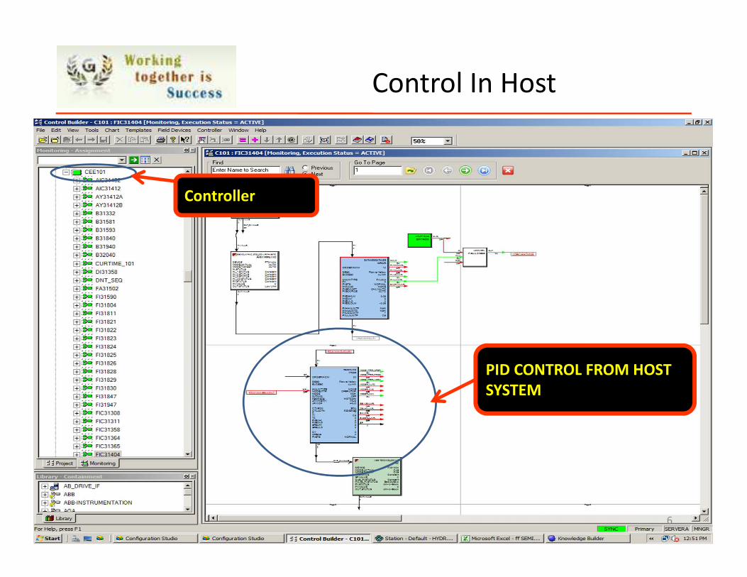
PID CONTROL FROM HOST
SYSTEM
Control In Host
Controller
7
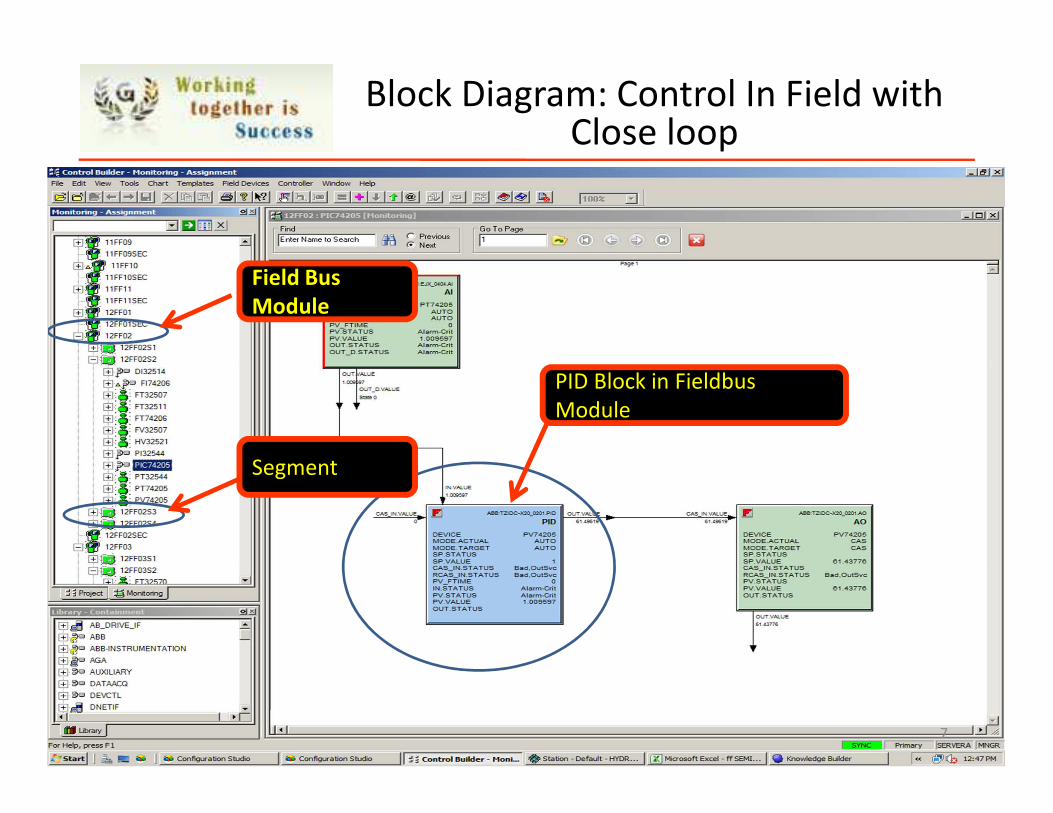
Block Diagram: Control In Field with Close loop
Field Bus
Module
Segment
PID Block in Fieldbus
Module
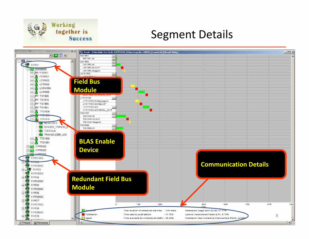
Segment Details
8
Field Bus
Module
Redundant Field Bus
Module
BLAS Enable
Device
Communication Details
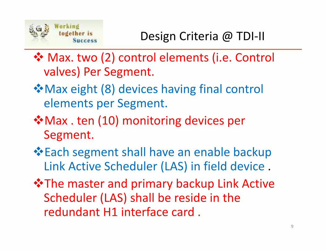
� Max. two (2) control elements (i.e. Control valves) Per Segment.
�Max eight (8) devices having final control elements per Segment.
�Max . ten (10) monitoring devices per Segment.
�Each segment shall have an enable backup Link Active Scheduler (LAS) in field device .
�The master and primary backup Link Active Scheduler (LAS) shall be reside in the redundant H1 interface card .
9
Design Criteria @ TDI-II
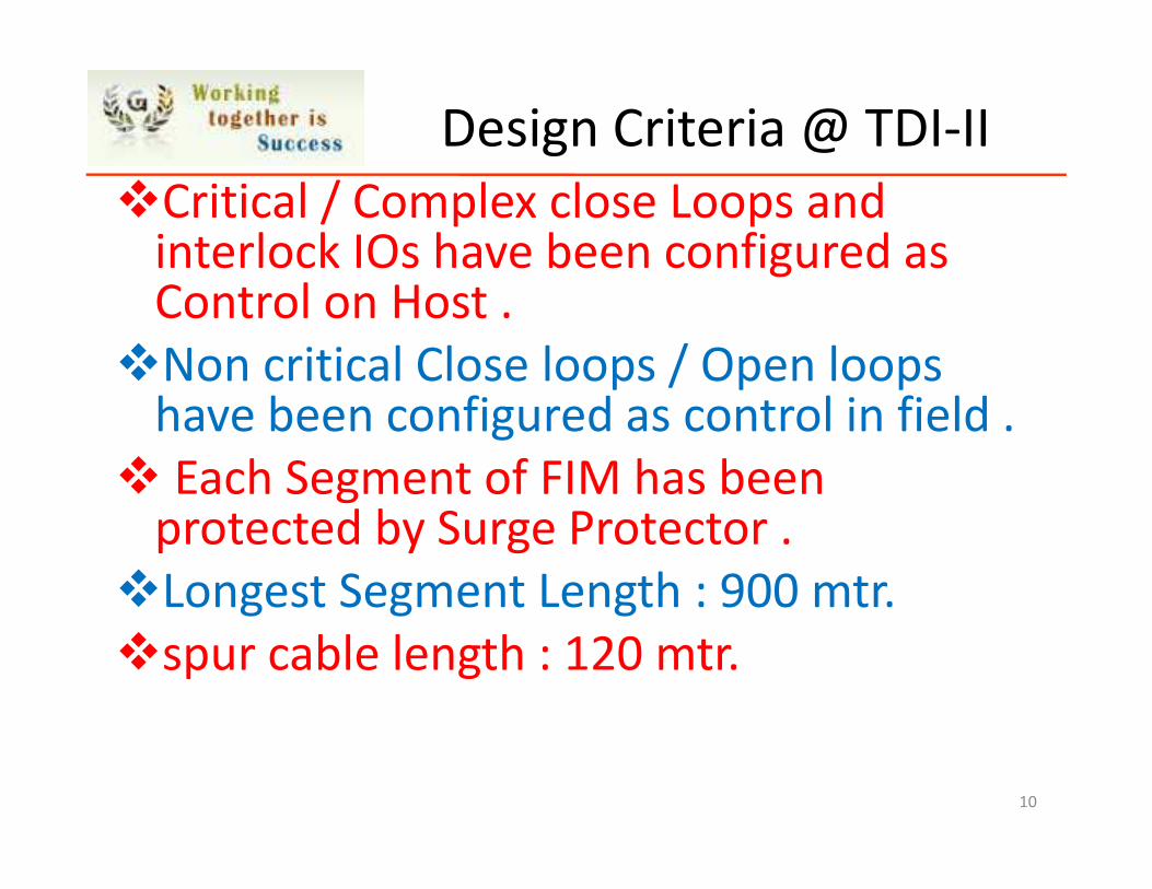
�Critical / Complex close Loops and interlock IOs have been configured as Control on Host .
�Non critical Close loops / Open loops have been configured as control in field .
� Each Segment of FIM has been protected by Surge Protector .
�Longest Segment Length : 900 mtr.
�spur cable length : 120 mtr.
10
Design Criteria @ TDI-II
Design Criteria @ TDI-II
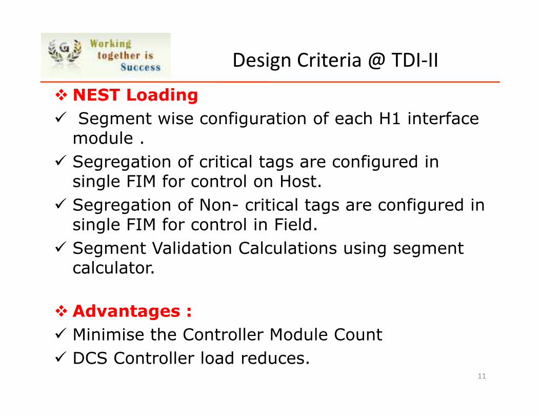
� NEST Loading
� Segment wise configuration of each H1 interface module .
� Segregation of critical tags are configured in single FIM for control on Host.
� Segregation of Non- critical tags are configured in single FIM for control in Field.
� Segment Validation Calculations using segment calculator.
� Advantages :
� Minimise the Controller Module Count
� DCS Controller load reduces.11
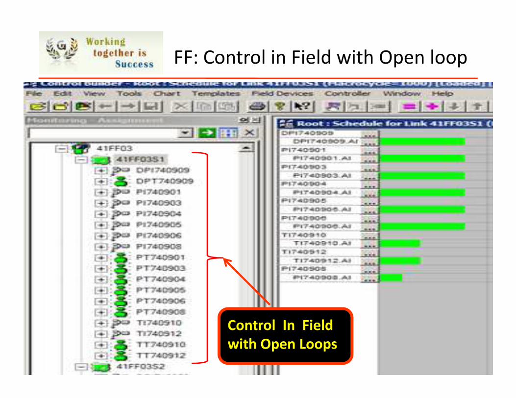
FF: Control in Field with Open loop
12
Control In Field
with Open Loops
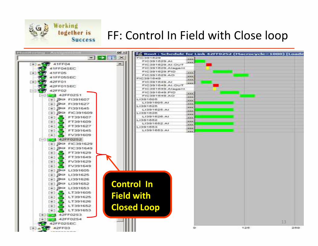
FF: Control In Field with Close loop
13
Control In
Field with
Closed Loop
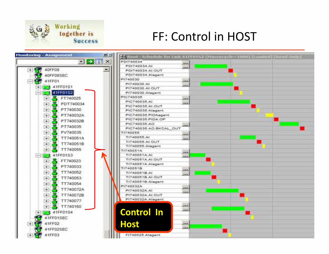
FF: Control in HOST
14
Control In
Host
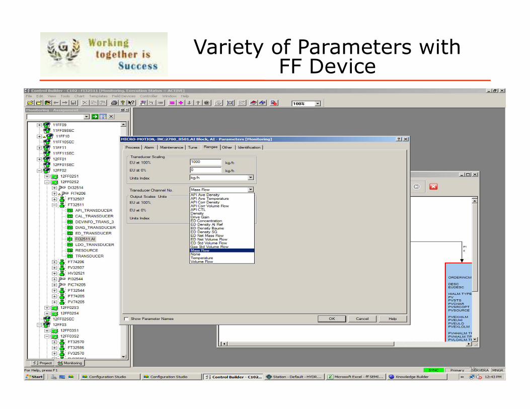
Variety of Parameters withFF Device
15
FF HARDWARE IMPLEMENTATION @ TDI-II
16
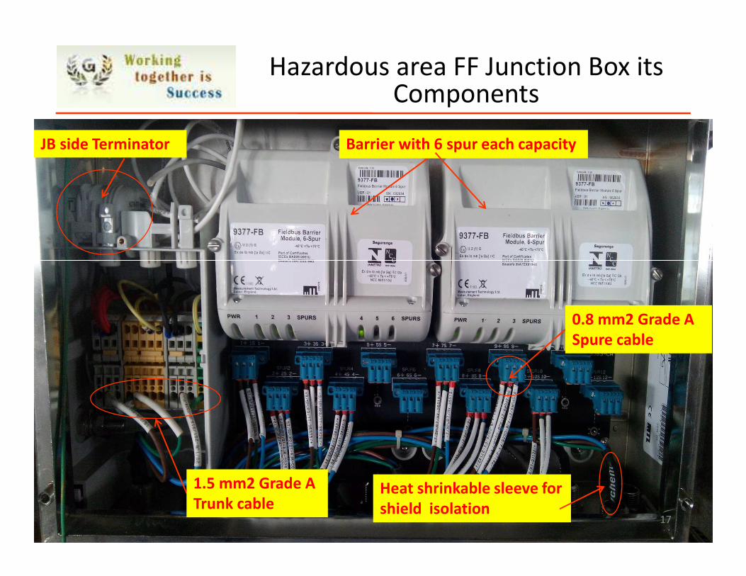
Barrier with 6 spur each capacity
Heat shrinkable sleeve for
shield isolation
JB side Terminator
0.8 mm2 Grade A
Spure cable
1.5 mm2 Grade A
Trunk cable
Hazardous area FF Junction Box its Components
17
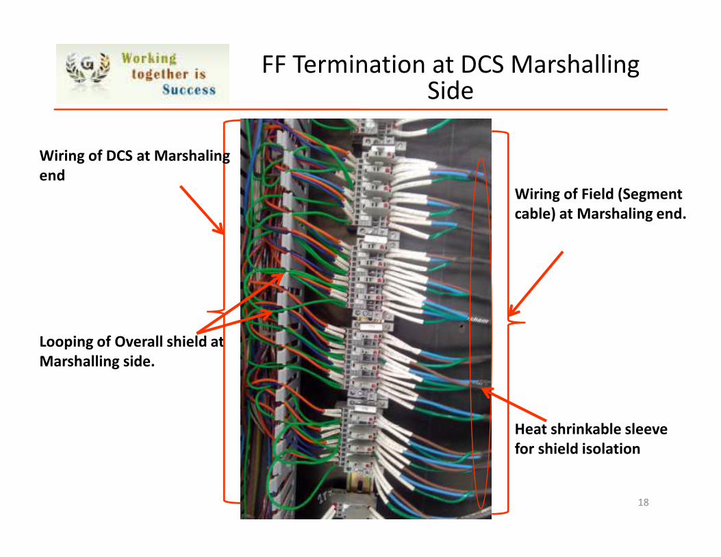
FF Termination at DCS Marshalling Side
Looping of Overall shield at
Marshalling side.
Wiring of DCS at Marshaling
end
Wiring of Field (Segment
cable) at Marshaling end.
Heat shrinkable sleeve
for shield isolation
18
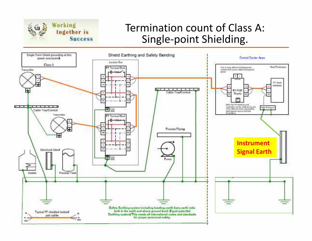
Termination count of Class A: Single-point Shielding.
19
Instrument
Signal Earth
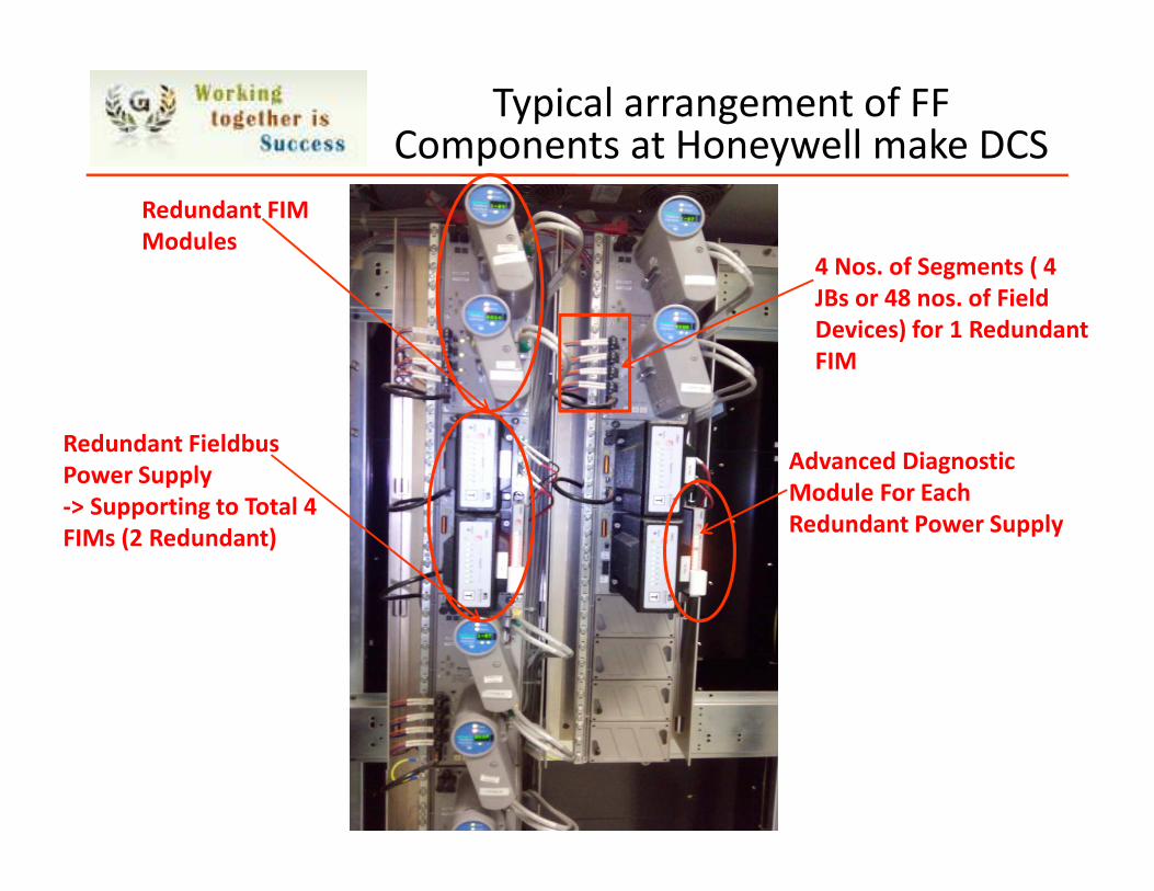
Typical arrangement of FF Components at Honeywell make DCS
Redundant FIM
Modules
Redundant Fieldbus
Power Supply
-> Supporting to Total 4
FIMs (2 Redundant)
Advanced Diagnostic
Module For Each
Redundant Power Supply
4 Nos. of Segments ( 4
JBs or 48 nos. of Field
Devices) for 1 Redundant
FIM

COMMISSIONING PROBLEMS
21
Device Description (DD) Files – It is set of protocol to talk between HOST and device and generally provided by Field device supplier.
� Non-Availability of (DD) Files.� For 2-3% of the cases DD files could not found easily.� System specific DD files.
� Nos. of revisions in DD file .
� Upgraded field device is not working with the earlier lower version of DD file.
� Configurable Ranges beyond Device Design Limit.� Field devices should not be configurable beyond its
design limit. Which creates confusion.� Non availability of basic variable units in Field Device
Library itself even though device was approved for ITK (Interoperability Test Kit) 4.1.
Commissioning Problems: DD Files
22
� Non-availability of Device Type Manager (DTM) file� With this file Asset management Server (AMS) can
have all the remote maintenance access of device.
� Generating system alarm as Configuration error without any detailed description.� Some of the field devices randomly generating
system error even though same make and model with same configuration.
� There is no specific guideline to identify the exact problem of configuration error.
� No specific guideline to configure Fieldbus Diagnostic module and its feature.
� Electronic Hardware Failure – FIM (H1 Cards)
� Electronic pH transmitters Failures – Complete segment affected.
Commissioning Problems
23
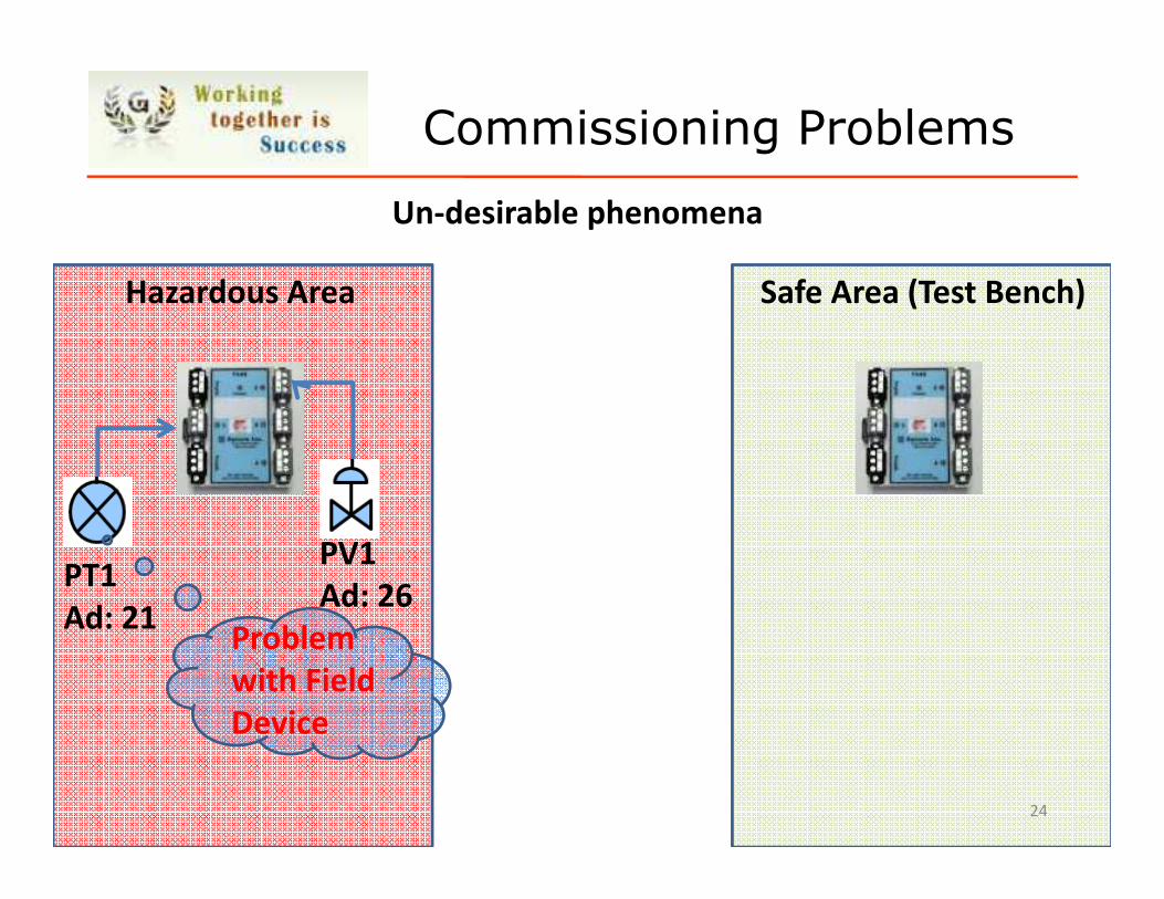
Un-desirable phenomena
PT1
Ad: 21
PV1
Ad: 26
Hazardous Area Safe Area (Test Bench)
Problem
with Field
Device
Commissioning Problems
24
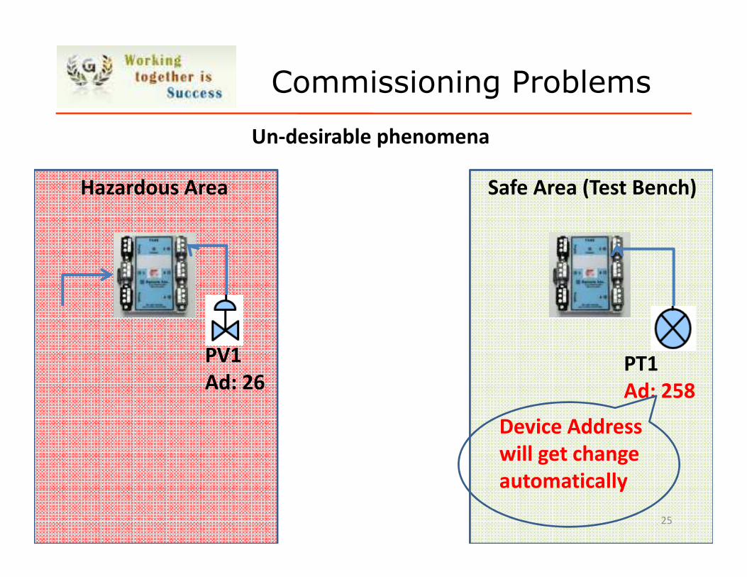
Un-desirable phenomena
PV1
Ad: 26
Hazardous Area Safe Area (Test Bench)
Commissioning Problems
25
PT1
Ad: 258
Device Address
will get change
automatically
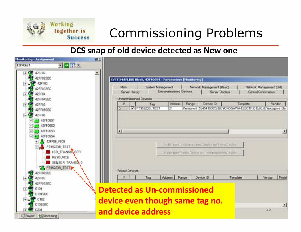
Commissioning Problems
DCS snap of old device detected as New one
26
Detected as Un-commissioned
device even though same tag no.
and device address
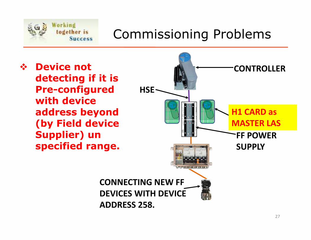
� Device not detecting if it is Pre-configured with device address beyond (by Field device Supplier) un specified range.
Commissioning Problems
27
CONNECTING NEW FF
DEVICES WITH DEVICE
ADDRESS 258.
HSE
FF POWER
SUPPLY
CONTROLLER
H1 CARD as
MASTER LAS
Commissioning Problems
28
HSE
FF POWER
SUPPLY
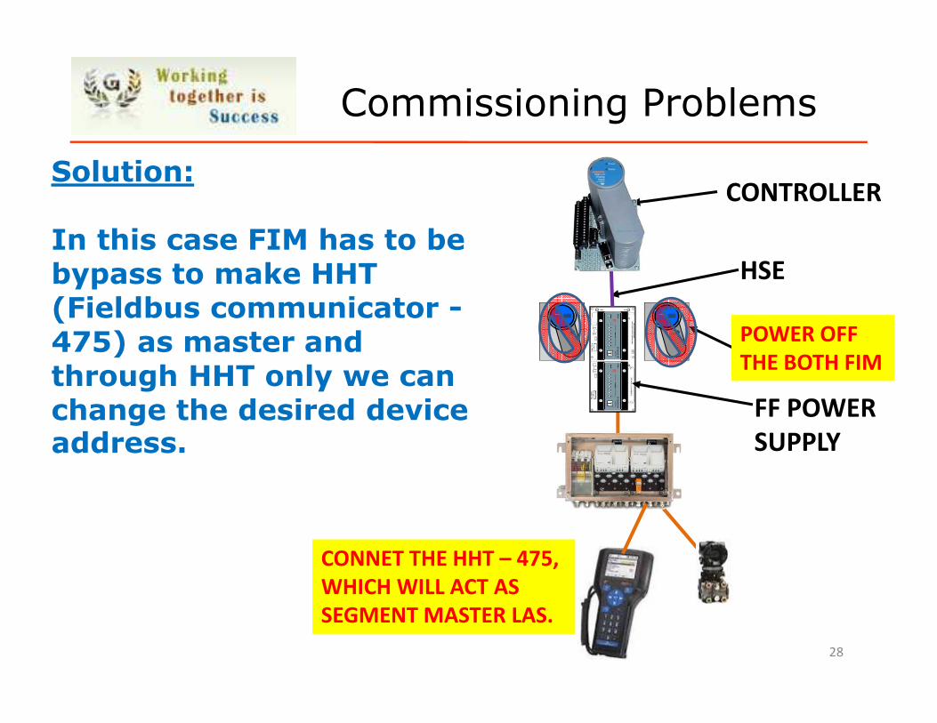
CONTROLLERSolution:
In this case FIM has to be bypass to make HHT (Fieldbus communicator -475) as master and through HHT only we can change the desired device address.
POWER OFF
THE BOTH FIM
CONNET THE HHT – 475,
WHICH WILL ACT AS
SEGMENT MASTER LAS.
General Guidelines
�Field Devices should be supplied as Pre configured with Tag no. and Device address from Vendor Works.
�All Variety of DD Files has to be checked during System FAT.
�Reserve 20% Spare in all aspects which will help in future maintenance.
29

Thank You
30

Questions
31
Troubleshooting
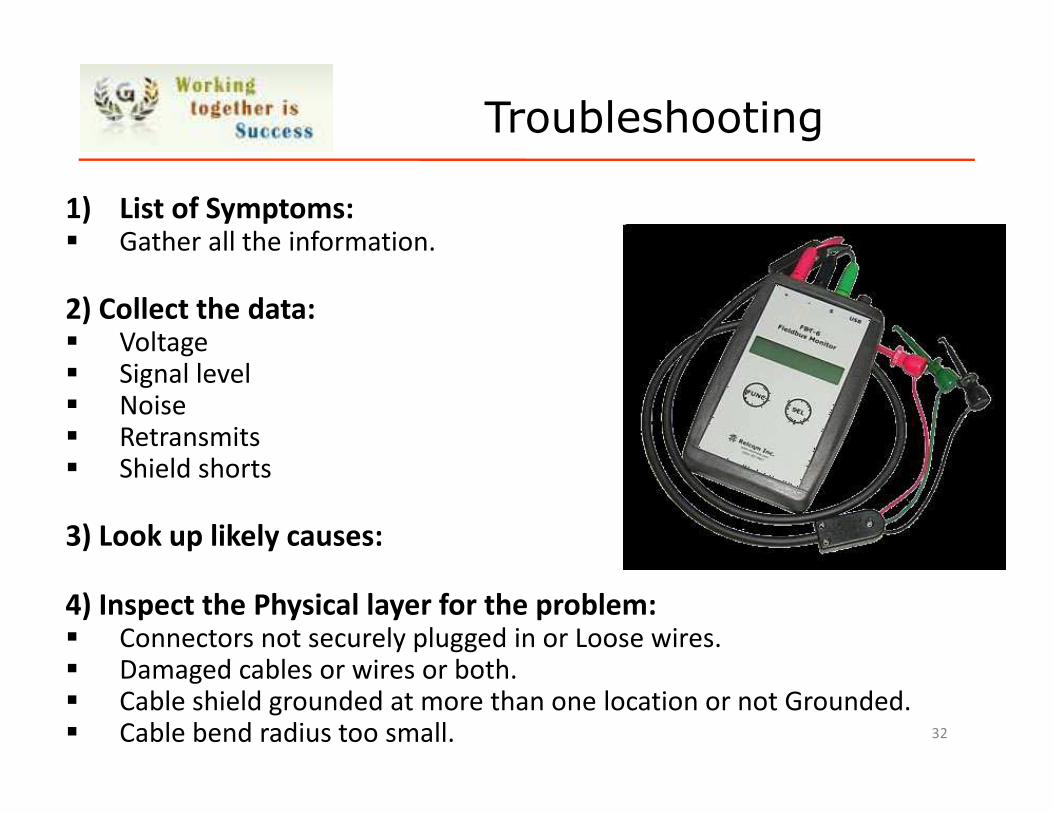
1) List of Symptoms: � Gather all the information.
2) Collect the data:� Voltage� Signal level� Noise� Retransmits� Shield shorts
3) Look up likely causes:
4) Inspect the Physical layer for the problem:� Connectors not securely plugged in or Loose wires.� Damaged cables or wires or both.� Cable shield grounded at more than one location or not Grounded.� Cable bend radius too small. 32
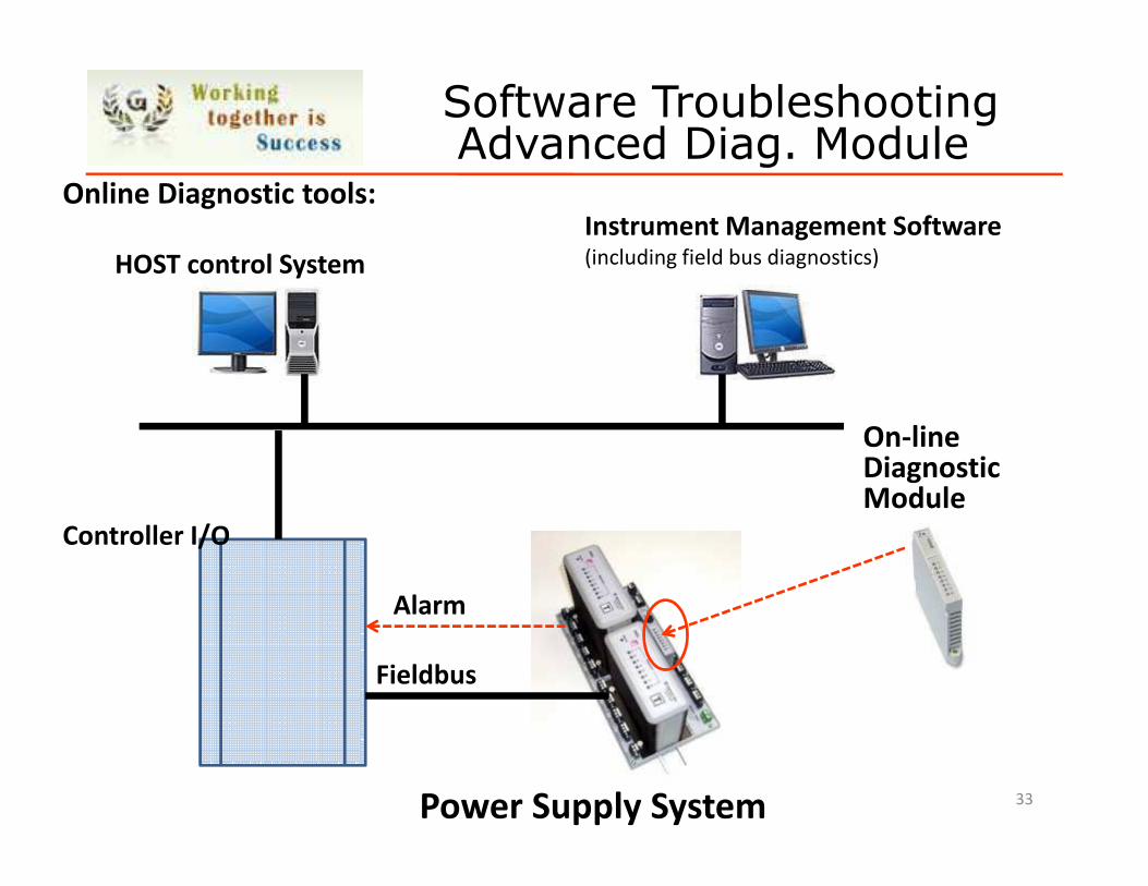
Online Diagnostic tools:
On-lineDiagnostic Module
Power Supply System
Controller I/O
Fieldbus
Alarm
HOST control System
Instrument Management Software(including field bus diagnostics)
Software TroubleshootingAdvanced Diag. Module
33
34
Customer Requirements
�Lower installation cost
Multiple instruments on a single pair of wiresFaster commissioning - loop checkMulti-variable transmitters
�Operational improvementsMore real time information “about” the processMeasurement validation - quality - safetyTighter control by distribution of control functionsMechanism for continuous innovation
�Lower maintenance costRemote access - unified toolsAdvanced process and device diagnosticsIntegrated plant asset management functions
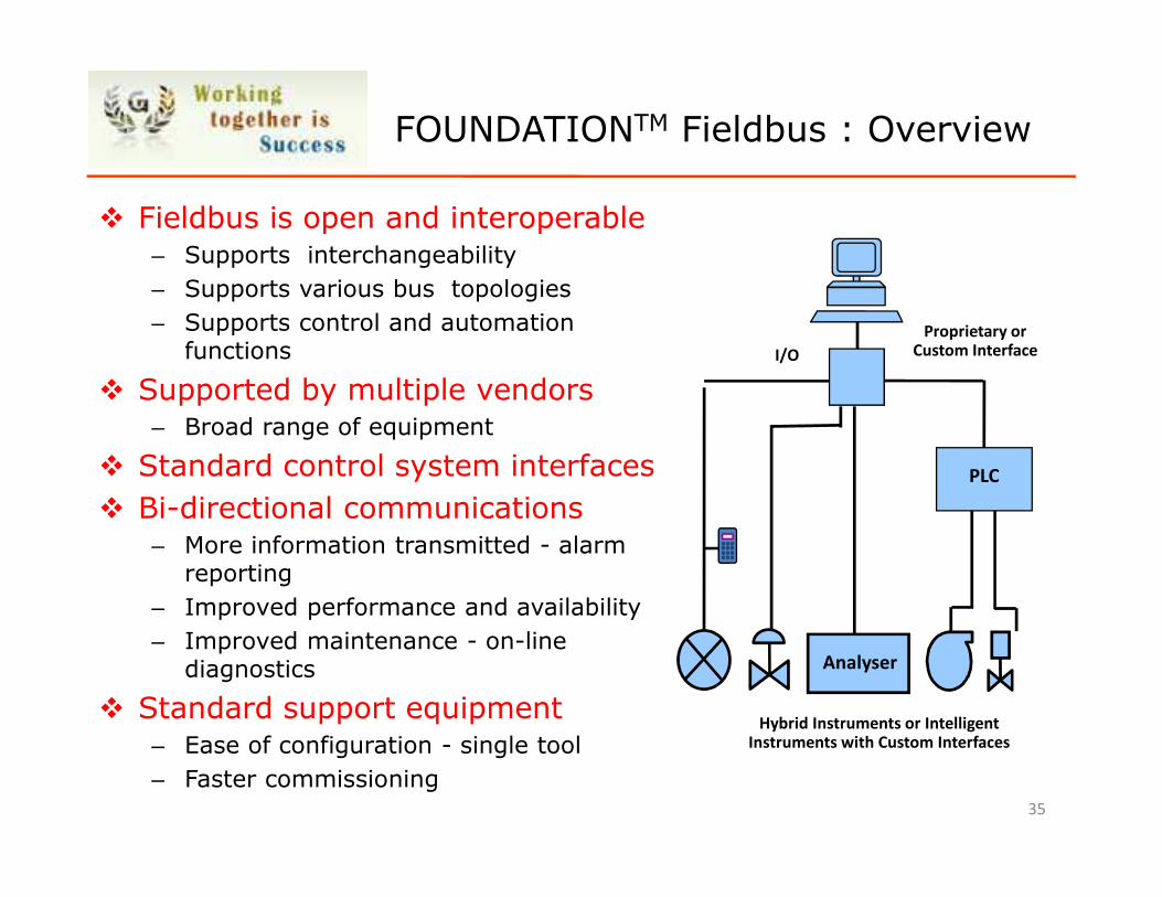
� Fieldbus is open and interoperable– Supports interchangeability
– Supports various bus topologies
– Supports control and automation functions
� Supported by multiple vendors– Broad range of equipment
� Standard control system interfaces
� Bi-directional communications– More information transmitted - alarm
reporting
– Improved performance and availability
– Improved maintenance - on-line diagnostics
� Standard support equipment– Ease of configuration - single tool
– Faster commissioning
Hybrid Instruments or Intelligent Instruments with Custom Interfaces
Analyser
Proprietary or Custom Interface
PLC
I/O
35
FOUNDATIONTM Fieldbus : Overview
36
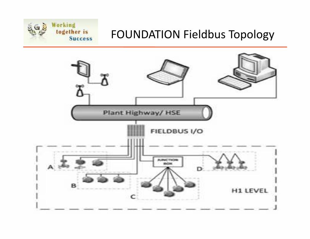
FOUNDATION Fieldbus Topology
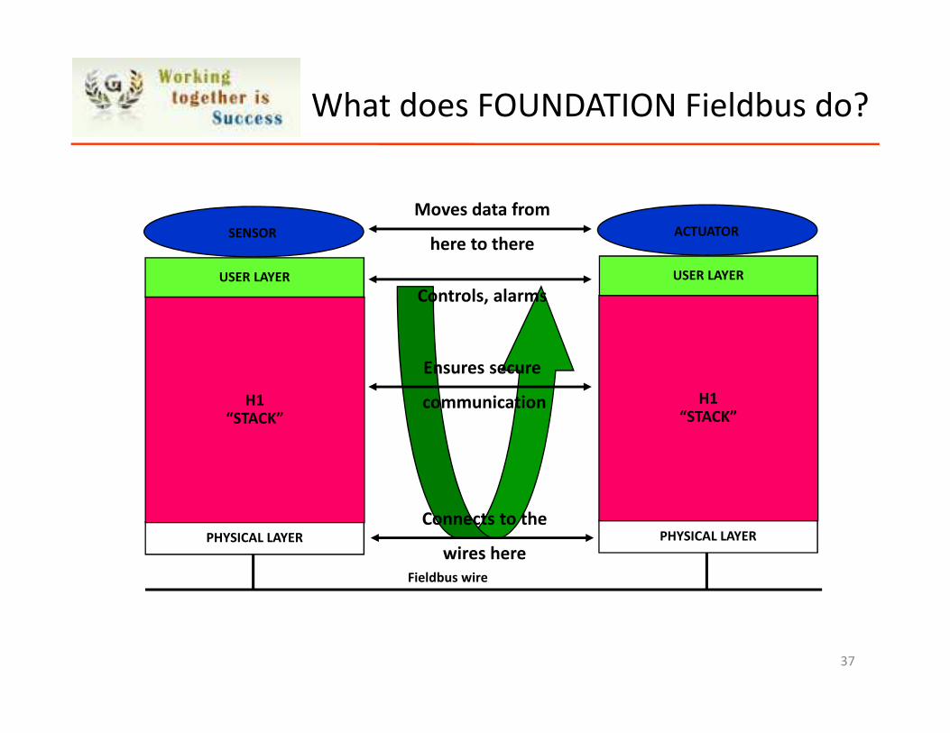
What does FOUNDATION Fieldbus do?
USER LAYER
PHYSICAL LAYER
H1“STACK”
SENSOR
Fieldbus wire
USER LAYER
PHYSICAL LAYER
H1“STACK”
ACTUATOR
Moves data from
here to there
Controls, alarms
Ensures secure
communication
Connects to the
wires here
37
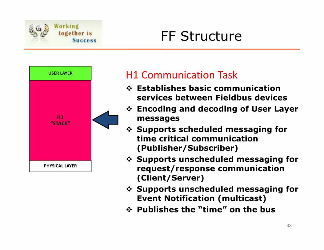
USER LAYER
PHYSICAL LAYER
H1“STACK”
H1 Communication Task� Establishes basic communication
services between Fieldbus devices
� Encoding and decoding of User Layer messages
� Supports scheduled messaging for time critical communication (Publisher/Subscriber)
� Supports unscheduled messaging for request/response communication (Client/Server)
� Supports unscheduled messaging for Event Notification (multicast)
� Publishes the “time” on the bus
38
FF Structure
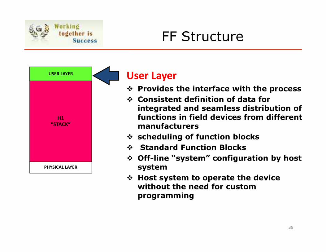
USER LAYER
PHYSICAL LAYER
H1“STACK”
User Layer� Provides the interface with the process
� Consistent definition of data for integrated and seamless distribution of functions in field devices from different manufacturers
� scheduling of function blocks
� Standard Function Blocks
� Off-line “system” configuration by host system
� Host system to operate the device without the need for custom programming
39
FF Structure
FF Structure
� The Resource Block
Describes the characteristics of a device
Contains manufacturer information
� The Transducer Block
Physical I/O interface with the actual sensor or actuator
Performs A/D conversions, square root extraction, linearization etc
Transmits/receives information to/from Function Blocks
The Transducer Block is the window to the process - diagnostics
� Function Blocks
Similar to the function blocks in today’s DCS and PLC systems
Mandatory is at least one Function Block depending on the type of device
40
Why FF over HART ?
�Integration of the digital protocol with 4–20 mA
Control Host
�Compatibility with Existing Control Wires
�Compatibility with Existing Knowledge Base and Work
Practices
�Multivariable Capability
�Control in the Field
�Alarms and Alerts
�Control and Calculation Capability
�Advance & Online Diagnostics
41
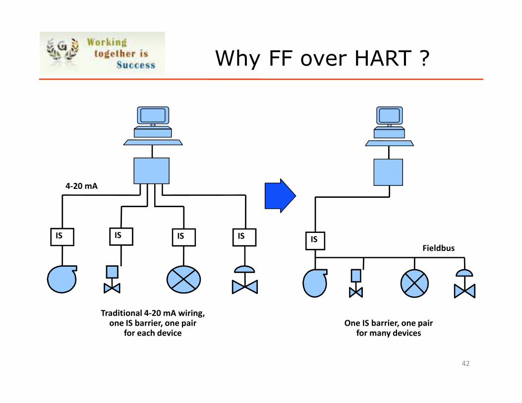
Why FF over HART ?
Traditional 4-20 mA wiring,one IS barrier, one pair
for each device
4-20 mA
ISISIS IS
One IS barrier, one pairfor many devices
ISFieldbus
42
Segment Calculation
� One of the Major Fieldbus designing tool
� Segment Calculator allows users to intuitively check
operational parameters to validate fieldbus segment
architecture.
� It provides a rapid “Go/No-Go” indication of the electrical
characteristics of the fieldbus network. All the relevant
parameters of the fieldbus segment are easily configurable,
including field device currents, cable lengths, cable cross-section
and number of fieldbus spurs. Power supply and host control
system types are easily selectable from pull-down menus, or can
be user-defined.
� Sample File : How to do Calculation ? 43
Pending points:
FF structure architecture
FIM failure prob.
pH cnductivity
44