Embed Size (px)
Citation preview
NRC FonM95 U.S. NUCLEAR REGULATORY COMMISSION DO ER
c NRC DISTRIBUTION FOR PART 50 DOCKET MATERIAL
TO:B. C.RSUCHE FROM: DUKE POWER CO. . DATE OF DOCUMENT
CHARLOTTE, N.C. 4/13/77 W.O.PARKER,JR. DATE RECEIVED
''4/18/77
OLETTER LDNOTORIZED PROP INPUT FORM NUMBER OF COPIES RECEIVED
ORIGINAL UNCLASSIFIED . fJCOPY I I
DESCRIPTION ENCLOSURE
LTR. RE. OUR 2/23/77 LTR.. .TRANS THE FOLLOWING. ADDITIONAL INFORMATION CONCERNING THE SEISMIC DESIGN FO THE OVERHEAD EMERGENCY POWER PATCH
. THROUGH THE 230 KV SWITCHYARD...... W/DRAWINGS
(iP) (34 P)
oE NOWLE DGE D
ISOQHOT REMOVE Af PLANT NAME OCONEE # 1,2 & 3 r.)
SAB
SAPETY FOR ACTION/INFORMATION NTRO ,ASSIGNED AD: I AST _n__D__
BRANCH CHIEF T.S P 4494tyP RANCH CHTPP* . PROJECT MANAGER: PROJECT MANAGER:
LIC, ASST, : LIC, ASST, :
INTERNAL DISTRIBUTION SYSTEMS SAFETY PLANT SYSTEMS SITE SAFETY &
NRC PDR HEINEMAN TEDESCO ENVTRO-ANALYSTS I & E SCHROEDER BENAROYA DENTON & TLRR OELD TATNAS GOSSICK & STAFF ENGINEERING IPPOLITO ENVIRO TEC. MIPC MACARRY - KTEKWO0 ERNST CASE BOSHAK BALLARD HANAUER SIHWEIL OPERATING REACTORS SPANGLER HARLESS PAWLICKI STELLO
SITE TECH, PROJECT MANAGEMENT REACTOR SAFETY OPERATING TECH. GAMMILL BOYD ROSS EISENHUT STEPP P. COLLINS NOVAK SHAO HULMAN HOUSTON ROSZTOCZY BAER
PETERSON CHECK BUTLER SITE ANALYSIS MELTZ GRIMES VOLLMER HELTEMES AT & I BUNCH SKOVHOLT SALTZMAN J. COLLINS
RUTBERG KREGER
EXTERNAL DISTRIBUTION CONTROL NUMBER
LPDR; W09 ZAT.AB: -!RQKHAVENAT- TAB.
_ TIC: REG V.IE ULRIYSON(QRNL ) N.S.IC: L-A PDR ASLB: CONSULTANTS: _/0___1
ACRS CYS HOLDING/ E T
NRC FORM 195 (2.76)
i.TK POW~ER COMPANY PowER BtILDING
422 SoUTH CHURaC STREET, CHARLOTTE, N. C. 2824:
WILLIAM 0. PARK(R.-JR. April 13, 1977 Vice PRESIOENT TL1PONEAtr 7 4
SrAme Pmonucion 37 -4083
REGULATORY DOC T FI COPY Mr. Benard C. Rusche, Director Office of Nuclear Reactor Regulation U. S. Nuclear Regulatory Commission Washington, D. C. 20555
Attention: Mr. A. Schwencer, Chief Operating Reactors Branch #1
Reference: Oconee Nuclear Station Docket Nos. 50-269, -270, -287
Dear Sir:
Your letter of February 23, 1977 requested additional information concerning the seismic design of the overhead emergency power path through the 230 KV switchyard at the Oconee Nuclear Station. This information is attached for your review.
Ver truly yours,
.William 0. Parker, Jr.
MST:ge Attachment
bc:M.H. B. Tucker 'A
Mr. J. E. Smith - - 4 Mr. K. S. Canady Mr. D. C. Holt Ms. L. J. Bare Mr. C. J. Wylie Mr. B. M. Rice Mr. L. C. Dail Master File OS-801.01 Section File OS-801.01
) 7/o9031~

OCONEE NUCLEAR STATION SEISMIC CAPABILITY OF EMERGENCY POWER PATH
REQUEST FOR ADDITIONAL INFORMATION
Question 1:
For each of the structures indicated in Table I, describe foundation condition, i.e., soil or rock, indicate how soil-structure interaction was accounted for, discuss what precautions were taken to stabilize the fill soil. Where applicable, provide the input response spectra, indicate the damping values and the extent to which a three directional earthquake was considered for the design and discuss the load combinations investigated.
Response:
Question I has been broken down into six parts as shown below. The response to each part is found in Table I and its associated notes.
la.. Describe foundation condition, i.e., soil or rock.
lb. Indicate how soil-structure interaction was accounted for.
Ic. Discuss what precautions were taken to stabilize the fill soil.
Id. Provide input response spectra and indicate the damping values.
le. Give directions of earthquake considered.
If. Give the load combinations investigated.
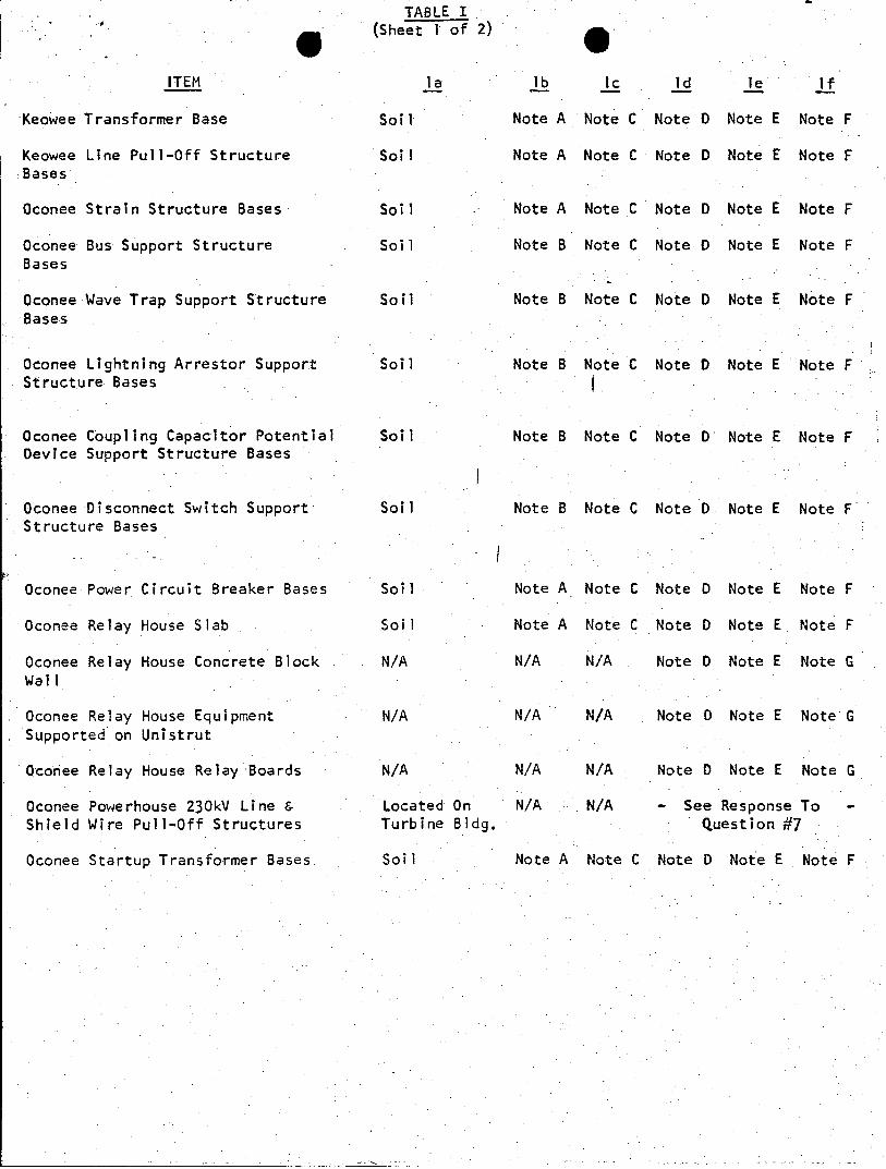
TABLE I (Sheet I of 2)
ITEM la lb Ic Id le If
Keowee Transformer Base Soil Note A Note C Note D Note E Note F
Keowee Line Pull-Off Structure Soil Note A Note C Note D Note E Note F Bases
Oconee Strain Structure Bases Soil Note A Note C Note D Note E Note F
Oconee Bus Support Structure Soil Note B Note C Note D Note E Note F Bases
Oconee Wave Trap Support Structure Soil Note B Note C Note D Note E Note F Bases
Oconee Lightning Arrestor Support Soil Note B Note C Note D Note E Note F Structure Bases
Oconee Coupling Capacitor Potential Soil Note 8 Note C Note D Note E Note F Device Support Structure Bases
Oconee Disconnect Switch Support Soil Note 8 Note C Note D Note E Note F Structure Bases
Oconee Power Circuit Breaker Bases Soil Note A Note C Note D Note E Note F
Oconee Relay House Slab Soil Note A Note C Note D Note E Note F
Oconee Relay House Concrete Block N/A N/A N/A Note D Note E Note G Wall
Oconee Relay House Equipment N/A N/A N/A Note D Note E Note G Supported on Unistrut
Oconee Relay House Relay Boards N/A N/A N/A Note D Note E Note G
Oconee Powerhouse 230kV Line & Located On N/A N/A - See Response To Shield Wire Pull-Off Structures Turbine Bldg. Question #7
Oconee Startup Transformer Bases Soil Note A Note C Note D Note E Note F

TABLE I (Sheet 2 of 2)
Note A: Friction between the base and the soil and passive earth pressure acting against the sides of the base are used to resist the horizontal sliding forces.
Note B: Passive earth pressure acting against the sides of the base is used to resist overturning forces and horizontal movement.
Note C: Fill soil was placed in accordance with Duke Power Company Specifications for compacted Group I fill, which requires soil to be compacted to 93% of standard proctor maximum density as indicated in Supplement 6 to PSAR, letter dated July 6, 1967.
Note D-: input Response Spectra is given in-Supplement #1 to PSAR question 8.5, plate 4. The acceleration from-the peak of the 2% damping curve was used for the static analysis of structures which is taken from page 8.4-1 of Supplement #1. Two percent damping is given for both steel frame structures and for reinforced concrete equipment supports. Concrete slabs and footings that are embedded in the soil are considered to have the same acceleration as the soil, which is .15g for the maximum hypothetical earthquakes as stated in Supplement #1 to the PSAR, Question 2.7.
Note E: A three dimensional earthquake was not used. Seismic forces were applied simultaneously in one horizontal direction and one vertical direction as described in Supplement #1 to PSAR, Question 8.4.2.
Note F: Load combinations were investigated in accordance with Volume II of the FSAR, Appendix 5A, Structural Design Bases, Section 5A.3, "Design Bases for Class 2 Structures." The most severe load combinations were dead load plus wind and dead load plus maximum hypothetical earthquake.
Note G: Load combinations were the same as given in Note F except that dead load plus wind load was not considered because the item is located inside the Relay House.

Describe the dynamic model of the transmission line and the towers. Indicate how the relative displacements of the ground between the towers during a seismic event are accounted for. Identify the critical sections on the transmission line, the towers, and their foundations, and provide a stress summary comparing the stresses against the acceptance criteria citing the applicable codes.
Response:
The 230kV transmission line from the Keowee Hydro Station to the Oconee Nuclear Station is 2596.4 feet in length and consists of two dead-end type lattice towers, one suspension lattice towerand the associated conductors. The transmission line is designed in accordance with the National Electric Safety Code (NESC) for heavy loading- conditions which is more -conservative than the medium loading conditions recommended by the NESC for the location of the plant.
The transmission line conductors are 795 MCM ACSR "Drake", pulled at a maximum tension of 10,000 pounds per the NESC heavy loading requirements, Section 25, Rule 251. The hardware and insulator ratings are in accordance with the NESC, Section 26, Rule 261-F. The conductor rating is in compliance with NESC, Section 26, Rule 261-H. The overhead shield wires are 0.5 inch diameter high strength steel pulled at a maximum tension of 8,000 pounds per the NESC heavy loading requirements, and its rating is in compliance with the NESC, Section 26, Rule 261-1. The structures are designed for NESC heavy loading Grade B construction per the NESC, Section 25, Rule 252,. and Section 26, Rule 261-A&B.
The dead-end structures and the suspension structure were analyzed as an unloaded pin-jointed truss by modal analysis for ground motion of 0.15g using Strudl Dynal. The resulting stresses for the members comprising these structures and the ultimate strength of the members are shown on Duke Power Company drawings 761115-1&2. The analysis demonstrates that the effects of 0.15g ground motion in combination with the normal dead and live wire loads will produce no overstress in any load-carrying members. The structures were analyzed without considering conductor loading because conductors tend to dampen tower vibration and limit tower deflections thus producing a less severe condition.
The overstressing of secondary bracing members in the dead-end structure is the most critical section of the transmission line (refer to Duke Power Company drawing 761115-1). However, failure of these secondary bracing members will not prevent the structure from carrying its load during a seismic event.
Question 3:
Describe the dynamic model of the 230kV Switchyard Relay House and provide the floor response spectra for different locations at which Category I equipment are supported. Identify the critical sections and provide a stress summary comparing the stresses against the acceptance criteria from applicable codes.
Response:
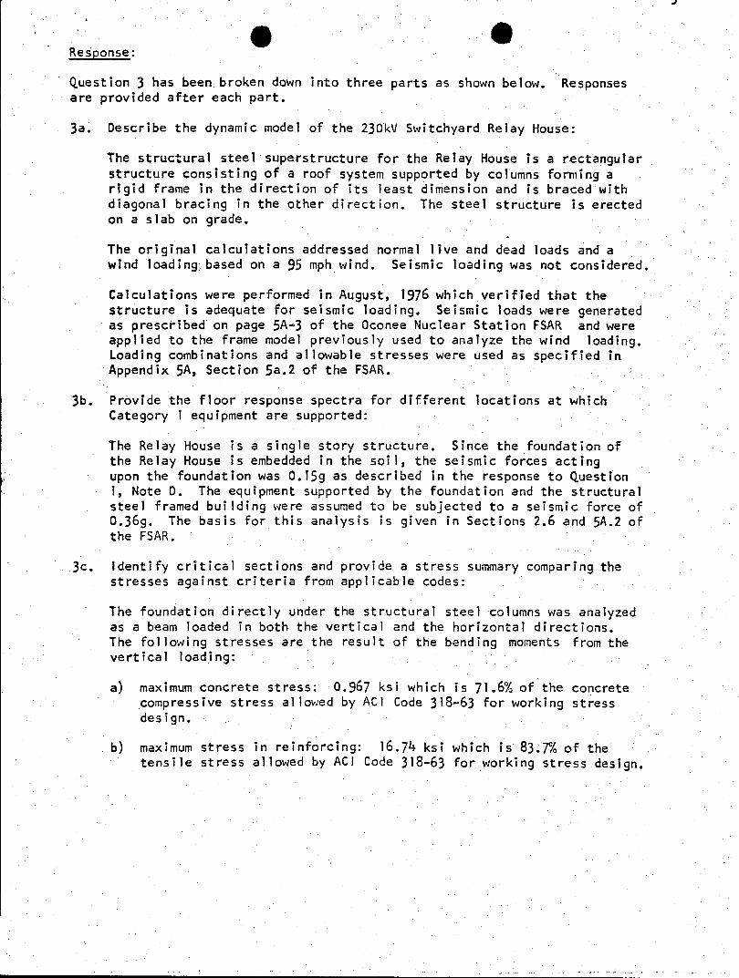
Question 3 has been.broken down into three parts as shown below. Responses are provided after each part.
3a. Describe the dynamic model of the 230kV Switchyard Relay House:
The structural steel superstructure for the Relay House is a rectangular structure consisting of a roof system supported by columns forming a rigid frame in the direction of its least dimension and is braced with diagonal bracing in the other direction. The steel structure is erected on a slab on grade.
The original calculations addressed normal live and dead loads and a wind loading.-based on a 95 mph wind. Seismic loading was not considered.
Calculations were performed in August, 1976 which verified that the structure is adequate for seismic loading. Seismic loads were generated as prescribed on page 5A-3 of the Oconee Nuclear Station FSAR and were applied to the frame model previously used to analyze the wind loading. Loading combinations and allowable stresses were used as specified in Appendix 5A, Section 5a.2 of the FSAR.
3b. Provide the floor response spectra for different locations at which Category I equipment are supported:
The Relay House is a single story structure. Since the foundation of the Relay House is embedded in the soil, the seismic forces acting upon the foundation was 0.15g as described in the response to Question 1, Note D. The equipment supported by the foundation and the structural steel framed building were assumed to be subjected to a seismic force of 0.369. The basis for this analysis is given in Sections 2.6 and 5A.2 of the FSAR.
3c. Identify critical sections and provide a stress summary comparing the stresses against criteria from applicable codes:
The foundation directly under the structural steel columns was analyzed as a beam loaded in both the vertical and the horizontal directions. The following stresses are the result of the bending moments from the vertical loading:
a) maximum concrete stress: 0.967 ksi which is 71.6% of the concrete compressive stress allowed by ACI Code 318-63 for working stress design.
b) maximum stress in reinforcing: 16.74 ksi which is 83.7% of the tensile stress allowed by ACl Code 318-63 for working stress design.
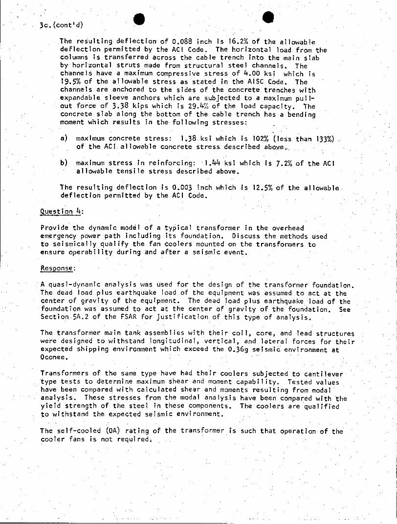
3c.(cont'd)
The resulting deflection of 0.088 inch is 16.2% of the allowable deflection permitted by the ACI Code. The horizontal load from the columns is transferred across the cable trench into the main slab by horizontal struts made from structural steel channels. The channels have a maximum compressive stress of 4.00 ksi which is 19.5% of the allowable stress as stated in the AISC Code. The channels are anchored to the sides of the concrete trenches with expandable sleeve anchors which are subjected to a maximum pullout force of 3.38 kips which is 29.4% of the load capacity. The concrete slab along the bottom of the cable trench has a bending moment which results in the following stresses:
a) maximum concrete stress: 1.38 ksi which is 102% (less than 133%) of the ACL allowable concrete stress described above,
b) maximum stress in reinforcing: 1.44 ksi which is 7.2% of the ACI allowable tensile stress described above.
The resulting deflection is 0.003 inch which is 12.5% of the allowable deflection permitted by the ACI Code.
Question 4:
Provide the dynamic model of a typical transformer in the overhead emergency power path including its foundation. Discuss the methods used to seismically qualify the fan coolers mounted on the transformers to ensure operability during and after a seismic event.
Response:
A quasi-dynamic analysis was used for the design of the transformer foundation. The dead load plus earthquake load of the equipment was assumed to act at the center of gravity of the equipment. The dead load plus earthquake load of the foundation was assumed to act at the center of gravity of the foundation. See Section 5A.2 of the FSAR for justification of this type of analysis.
The transformer main tank assemblies with their coil, core, and lead structures were designed to withstand longitudinal, vertical, and lateral forces for their expected shipping environment which exceed the 0.36g seismic environment at Oconee.
Transformers of the same type have had their coolers subjected to cantilever type tests to determine maximum shear and moment capability. Tested values have been compared with calculated shear and moments resulting from modal analysis. These stresses from the modal analysis have been compared with the yield strength of the steel in these components. The coolers are qualified to withstand the expected seismic environment.
The self-cooled (OA) rating of the transformer is such that operation of the cooler fans is not required.
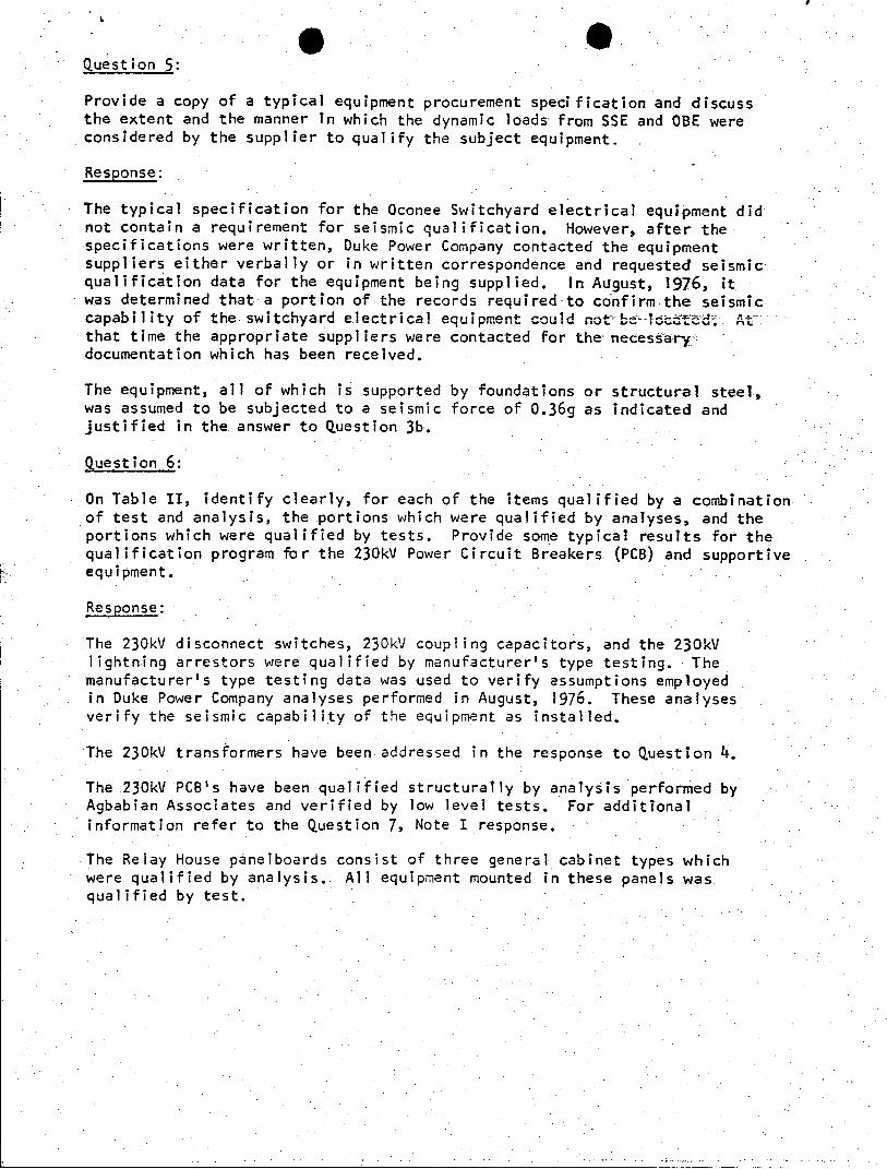
Question 5:
Provide a copy of a typical equipment procurement specification and discuss the extent and the manner in which the dynamic loads from SSE and OBE were considered by the supplier to qualify the subject equipment.
Response:
The typical specification for the Oconee Switchyard electrical equipment did not contain a requirement for seismic qualification. However, after the specifications were written, Duke Power Company contacted the equipment suppliers either verbally or in written correspondence and requested seismic qualification data for the equipment being supplied. In August, 1976, it was determined that a portion of the records required-to confirm the seismic capability of the switchyard electrical equipment could not beocetted At that time the appropriate suppliers were contacted for the necessarydocumentation which has been received.
The equipment, all of which is supported by foundations or structural steel, was assumed to be subjected to a seismic force of 0.36g as indicated and justified in the answer to Question 3b.
Question 6:
On Table II, identify clearly, for each of the items qualified by a combination of test and analysis, the portions which were qualified by analyses, and the portions which were qualified by tests. Provide some typical results for the qualification program fbr the 230kV Power Circuit Breakers (PCB) and supportive equipment.
Response:
The 230kV disconnect switches, 230kV coupling capacitors, and the 230kV lightning arrestors were qualified by manufacturer's type testing. - The manufacturer's type testing data was -used to verify assumptions employed in Duke Power Company analyses performed in August, 1976. These analyses verify the seismic capability of the equipment as installed.
The 230kV transformers have been addressed in the response to Question 4.
The 230kV PCB's have been qualified structurally by analysis performed by Agbabian Associates and verified by low level tests. For additional information refer to the Question 7, Note I response.
The Relay House panelboards consist of three general cabinet types which were qualified by analysis. All equipment mounted in these panels was qualified by test.
Question 7:
For items or portions.of items qualified by analysis provide the following information:
a. State whether the analysis method was static or dynamic, and justify your selection.
b. Provide a diagram of the math model used for each equipment item.
c. Provide input loads used in the analysis and point of application.
d. Show location and magnitude of the highest stress intensity and deflection, and list the corresponding margins of safety.
e. Verify that the operability of each equipment item was considered in your analysis and provide a discussion on how the calculated deflect as were considered in relation to the operability of the component.
f. Define the acceptance criteria used in the operability analysis.
Response:
Question 7 has been broken down into six parts as shown below. The response to each part is found in Table II and its associated notes.
7a. State whether static or dynamic analysis was used and justify.
7b. Provide math model used for each equipment item.
7c. Give input loads and point of application.
7d. Indicate location and magnitude of the highest stress and deflection and list the corresponding margins of safety.
7e. Operability considerations
7f. Operability acceptance criteria
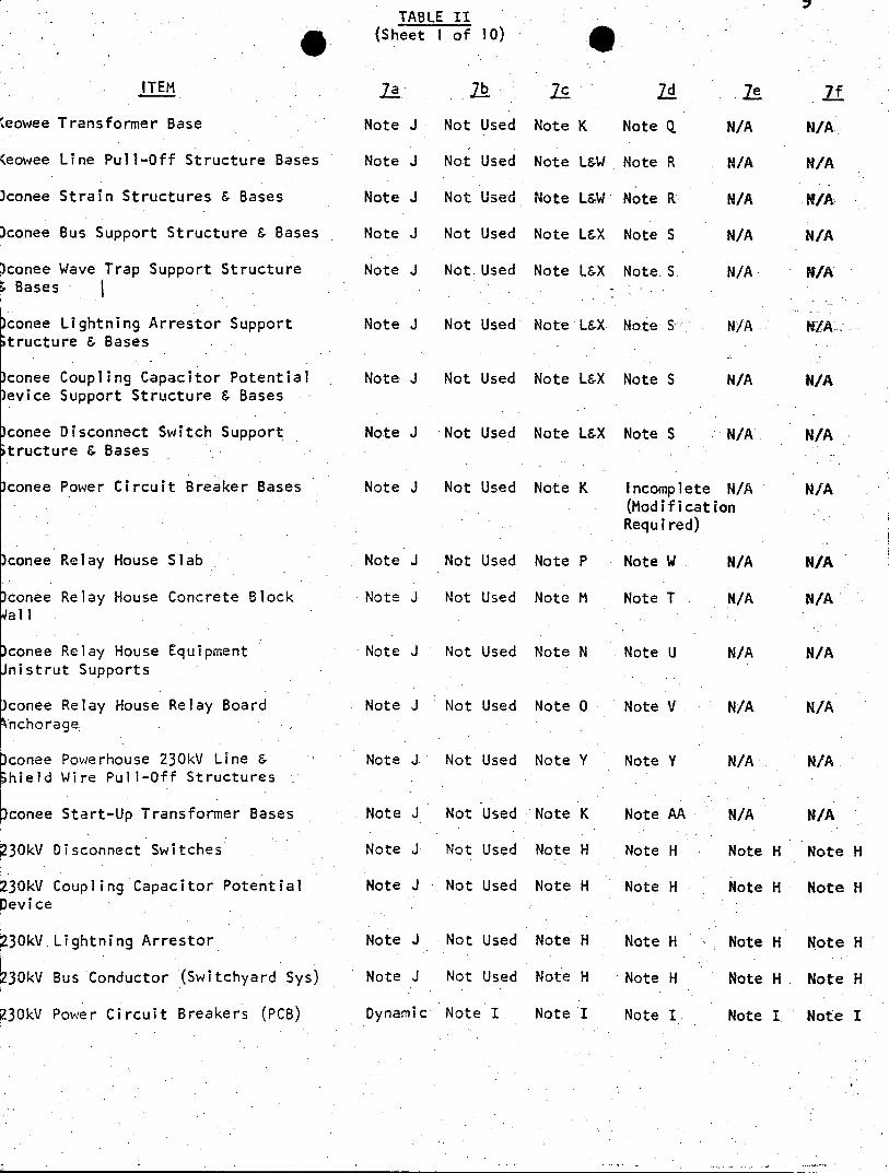
TABLE II (Sheet I of 10)
ITEM ]a lb -C 2d he
teowee Transformer Base Note J Not Used Note K Note Q N/A N/A
(eowee Line Pull-Off Structure Bases Note J Not Used Note L&W Note R N/A N/A
conee Strain Structures & Bases Note J Not Used Note L&W Note R N/A N/A
conee Bus Support Structure & Bases Note J Not Used Note L&X Note S N/A N/A
conee Wave Trap Support Structure Note J Not Used Note L&X Note S N/A N/A Bases
conee Lightning Arrestor Support Note J Not Used Note L&X Note S N/A A tructure & Bases
)conee Coupling Capacitor Potential Note J Not Used Note L&X Note S N/A N/A evice Support Structure & Bases
conee Disconnect Switch Support Note J Not Used Note L&X Note S N/A N/A tructure & Bases
conee Power Circuit Breaker Bases Note J Not Used Note K Incomplete N/A N/A (Modification Required)
conee Relay House Slab Note J Not Used Note P Note W N/A N/A
conee Relay House Concrete Block Note J Not Used Note M Note T N/A N/A all
conee Relay House Equipment Note J Not Used Note N Note U N/A N/A nistrut Supports
conee Relay House Relay Board Note J Not Used Note 0 Note V N/A N/A nchorage
conee Powerhouse 230kV Line & Note J. Not Used Note Y Note Y N/A N/A hield Wire Pull-Off Structures
conee Start-Up Transformer Bases Note J Not Used Note K Note AA N/A N/A
30kV Disconnect Switches Note J Not Used Note H Note H Note H Note H
30kV Coupling Capacitor Potential Note J Not Used Note H Note H Note H Note H evice
30kV.Lightning Arrestor Note J Not Used Note H Note H Note H Note H
30kV Bus Conductor (Switchyard Sys) Note J Not Used Note H Note H Note H Note H
30kV Power Circuit Breakers (PCB) Dynamic Note I Note I Note I Note I Note I
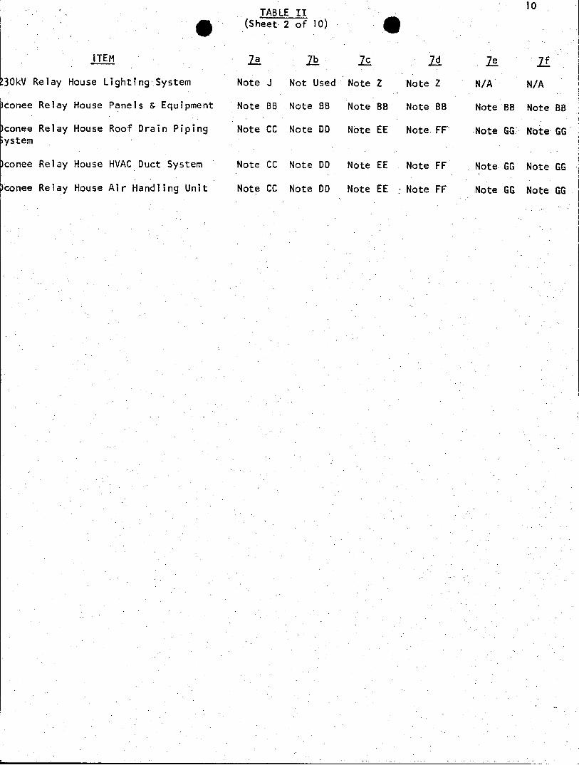
TABLE II (Sheet 2 of 10)
ITEM ja lb 7c 7f
30kV Relay House Lighting System Note J Not Used Note Z Note Z N/A N/A
conee Relay House Panels & Equipment Note BB Note BB Note BB Note BB Note BB Note BB
conee Relay House Roof Drain Piping Note CC Note DD Note EE Note FF Note GG Note GG ystem
conee Relay House HVAC Duct System Note CC Note DD Note EE Note FF Note GG Note GG
conee Relay House Air Handling Unit Note CC Note DD Note EE Note FF Note GG Note GG
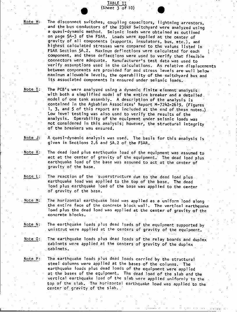
TABLE IT (Sheet 3 of 10)
Note H: The disconnect switches, coupling capacitors, lightning arrestors, and the bus conductors of the 230kV Switchyard were analyzed using a quasi-dynamic method. Seismic loads were obtained as outlined on page 5A-3 of the FSAR. Loads were applied at.the center of gravity of all components (supports, insulators, bus, etc.), and highest calculated stresses were compared to the values listed in FSAR Section 5A.2. Maximum deflections were calculated for each component, and these deflections were used to verify that flexible connectors were adequate. Manufacturer's test data was used to verify assumptions used in the calculations. As relative displacements between components are provided for and stress levels are well below maximum allowable levels, the operability of the -switchyard bus and its associated components is ensured under seismic loads.
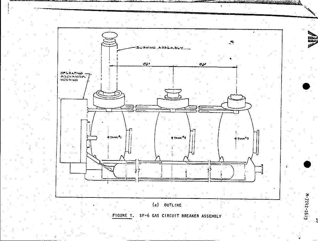
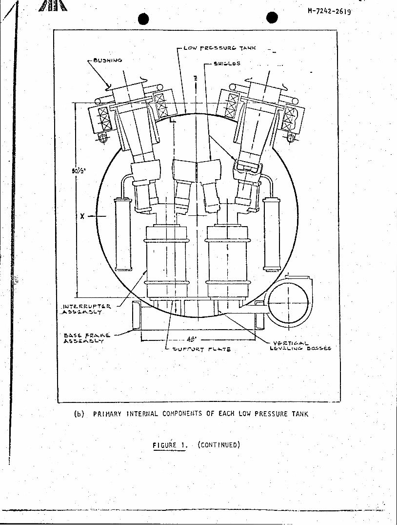
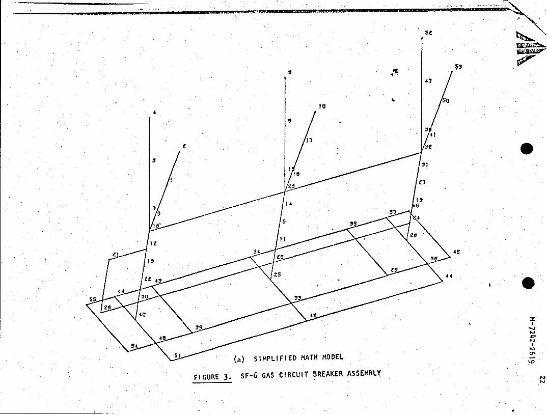
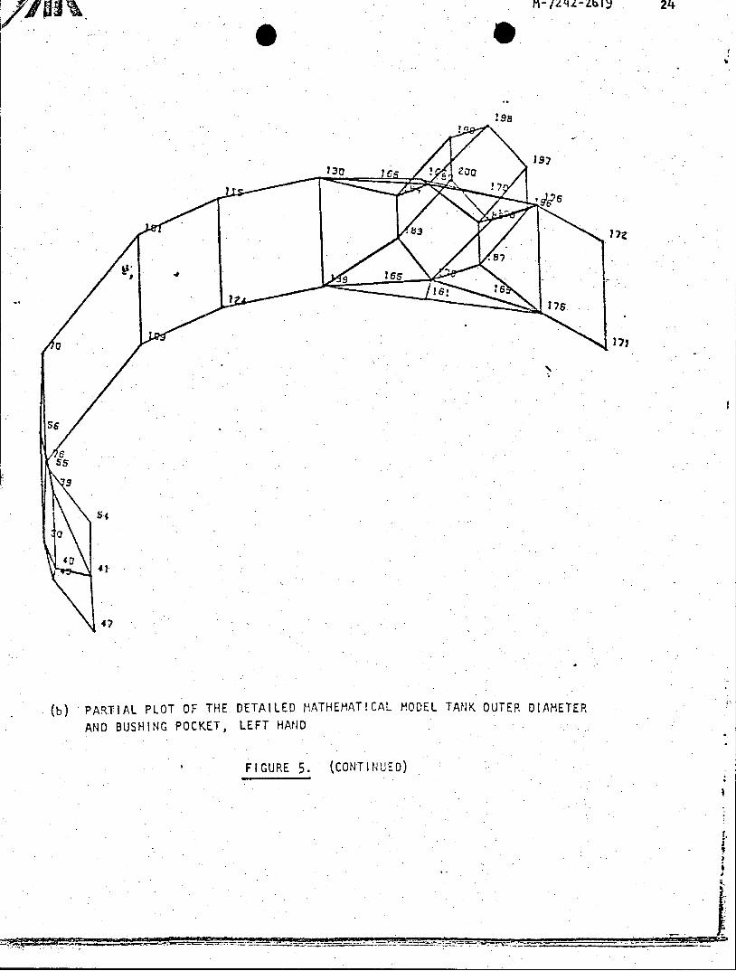
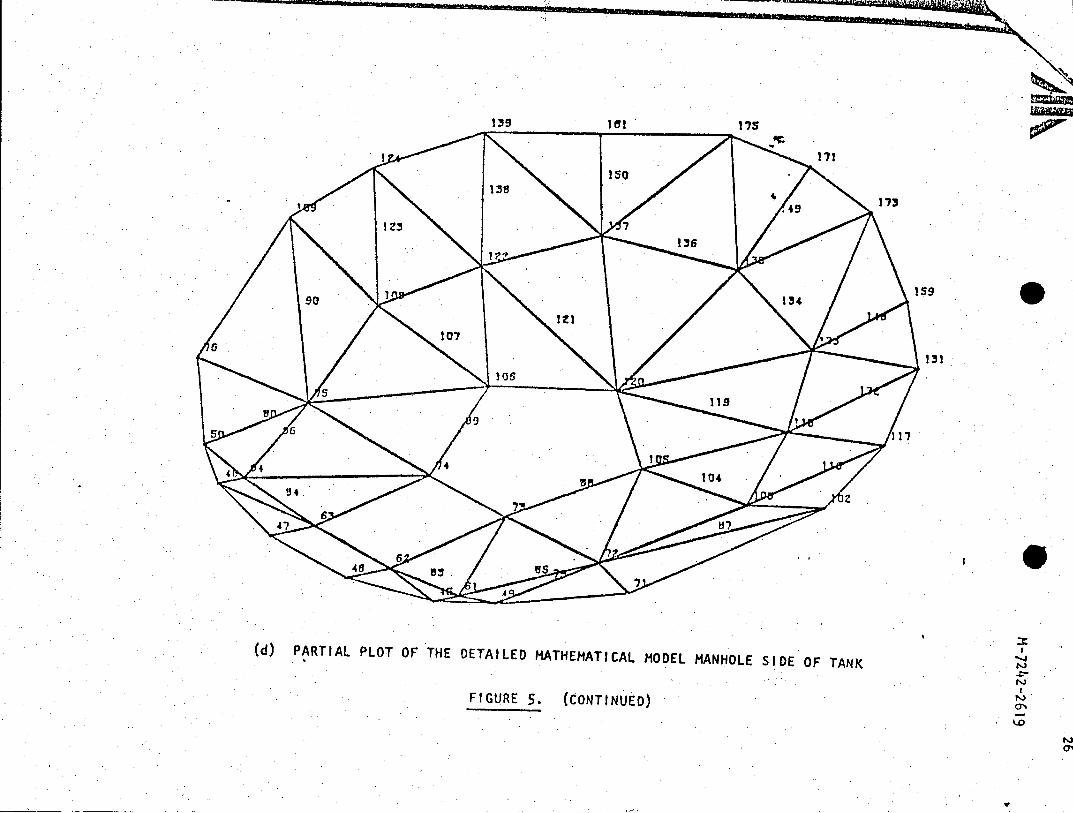
Note I: The PCB's were analyzed using a dynamic finite element analysiswith both a simplified model of the entire breaker and a detailedmodel of one tank assembly. A description of the analysis is contained in the Agbabian Associates' Report M-7242-2619. (Figures 1, 3, and 5 of this report are included at the end of these notes.) Low level testing was also used to verify the results of the analysis. Operability of the equipment under seismic loads was not considered in this analysis; however, the structural integrity of the breakers was ensured.
Note J: A quasi-dynamic analysis was used. The basis for this analysis is given in Sections 2.6 and 5A.2 of the FSAR.
Note K: The dead load plus earthquake load of the equipment was assumed to act at the center of gravity of the equipment. The dead load plus earthquake load of the base was assumed to act at the center of gravity of the base.
Note L: The reaction of the superstructure due to the dead load plus earthquake load was applied to the top of the base. The dead load plus earthquake load of the base was applied to the center of gravity of the base.
Note M: The horizontal earthquake load was applied as a uniform load along the entire face of the concrete block wall. The vertical earthquake load plus the dead load was applied at the center of gravity of the concrete blocks.
Note N: The earthquake loads plus dead loads of the equipment supported by unistrut were applied at the centers of gravity of the equipment.
Note 0: The earthquake loads plus dead loads of the relay boards and duplex cabinets were applied at the centers of gravity of the duplex cabinets.
Note P: The earthquake loads plus dead loads carried by the structural steel columns were applied at the bases of the columns. The earthquake loads plus dead loads of the equipment were applied at the bases of the equipment. The dead load of the slab and the vertical earthquake load of the slab were applied uniformly to the top of the slab. The horizontal earthquake load was applied to the center of gravity of the slab.

12 TABLE II
(Sheet 4 of 10)
Note Q: The transformer has a safety factor of 1.13 against overturning and a safety factor of 1.37 against the transformer base sliding in soil. Restraints were required to prevent the transformer from sliding on the base. The highest stress in the restraint is a mid span bending stress of 19.96 ksi which is 91% of the allowable stress as stated in the AISC Code. The resulting deflection is 0.02 Inches which is 40% of allowable.
Note R: The minimum factor of safety against overturning is 3.08. The maximum stresses due to bending in the reinforced concrete base are as follows:
a) Maximum concrete stress: 1.3 ksi, which is 97% of the concrete compressive stress allowed by ACI Code 318-63 for working stress design.
b) Maximum stress in reinforcing: 25.9 ksi which is 129%A of the tensile stress allowed by ACI Code 318-63 for working stress design. (ACI 318-63 for working stress design permits 133% of allowable stress for loading combinations that include wind loads or seismic loads.)
Note S: See table below:
Maximum Bending Stress In Critical Soil Pressure Reinforced Concrete Footing
Actual Actual as a % Actual as a Soil of Allowable of Allowable
Depth Pressure Determined By Depth Permitted By ACI Code Item (Feet) (KSF) Testing (Feet) Concrete Reinf.
Bus Support 2.94 0.649 49% 2.94 80% 40%
Wave Trap 2.32 0.732 60% 2.32 127% 106%
Lightning 2.51 0.546 48% 2.51 55% 37% Arrestor
Coupling 2.28 0.942 91% 2.28 124% 107% Capacitor
Disconnect 8.875 3.57 98% 2.90 116% 98% Switch
ACI 318-63 for working stress design permits 133% of allowable stresses for loading combinations that include wind loads or seismic loads.
Note T: The maximum stress in thesteel support for the concrete block wall is a bending stress of 5.76 ksi at the bottom of the support. This stress if 26% of the allowable stress from the AISC Code. The resulting deflection of 0.21 inches would occur at the top of the support. The deflection if 64% of the allowable deflection from the AISC Code. The stress in the horizontal joint reinforcing is 28% of the allowable stress.

TABLE II (Sheet 5 of 10)
Note U: The maximum stress in the unistruts occurs in the vertical unistruts supporting the DC panelboards. The maximum stress of 8.79 ksi is the combined stress due to bending and axial load and is 76% of the allowable stress. The resulting maximum deflection, which occurs near the middle of the members, is 0.28 inches. This deflection is 85% of the allowable deflection as stated in the AISC Code.
Note V: The highest stress occurs in the steel channel embedded in the concrete floor. Seismic forces acting on the relay boards will induce a bending stress of 7.55 ksi in the channel which is 32% of the stress allowed by the AISC Code. The resulting deflection in the channel would be 0.006 inches which is-12% of the.deflection allowed by the AISC Code.
Note W: The Keowee 230kV Line Pull-Off Structures and the Oconee 230k-V Strain Structures are made up of a series of A-frames connected by two beams, laced together to form a truss, which forms a rigid frame structure.
The original calculations were performed by Lehigh Structural Steel Company in accordance with Duke Power Company's Specification OS-343/KS-343. The Specification addressed normal live and dead loads, line pulls, wind loading based on winds in excess of 95 mph, and seismic loading as prescribed on page 5A.3 of the Oconee Nuclear Station FSAR. Loading combinations were in accordance with Appendix 5A, Section 5A.2 of the FSAR. Lehigh concluded that load combinations with seismic loads were less critical than other load combinations. Additional calculations were performed in August, 1976 by Duke Power Company which verified Lehigh's conclusion.
Note X: The 230kV Switchyard Bus Support Structure, Wave Trap Support Structure, Lightning Arrestor Support Structure, Coupling Capacitor Support Structures, and Disconnect Switch Support Structures make up what is termed the 230kV Switchyard Low Structures. These structures are all single leg cantilevers.from a concrete foundation with the exception of the Disconnect Switch Support Structure which consists of two cantilevers sharing equal loads.
These structures were originally purchased per designs which had been successfully used in the past and, therefore, no original calculations are available for these specific structures.
Calculations were performed in August, 1976 which addressed normal live and dead loads, wind loading based on a 95 mph wind,and seismic loads. Seismic loads were generated as prescribed in page 5A-3 of the Oconee Nuclear Station FSAR. Loading combinations and allowable stresses were used as specified in Appendix 5A, Section 5A-2 of.the FSAR.. All calculated stresses for all loading combinations were less than the allowable stresses.
T-4 TABLE II
(Sheet 6 of 0)
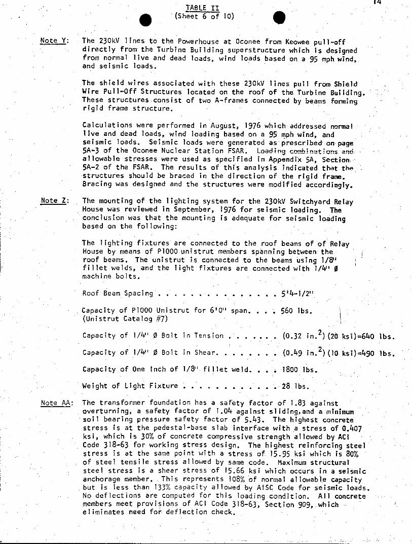
Note Y: The 230kV lines to the Powerhouse at Oconee from Keowee pull-off directly from the Turbine Building superstructure which is designed from normal live and dead loads, wind loads based on a 95 mph wind, and seismic loads.
The shield wires associated with these 230kV lines pull from Shield Wire Pull-Off Structures located on the roof of the Turbine Building. These structures consist of two A-frames connected by beams forming rigid frame structure.
Calculations were performed in August, 1976 which addressed nom! live and dead loads, wind loading based on a 95 mph wind, and seismic loads. Seismic loads were generated as prescribed on page 5A-3 of the Oconee Nuclear Station FSAR. Loading nnah-;rto acnd allowable stresses were used as specified in Appendix 5A, Section 5A-2 of the FSAR. The results of this analysis indicated that the structures should be braced in the direction of the rigid frame. Bracing was designed and the structures were modified accordingly.
Note Z: The mounting of the lighting system for the 230kV Switchyard Relay House was reviewed in September, 1976 for seismic loading. The conclusion was.that the mounting is adequate for seismic loading based on the following:
The lighting fixtures are connected to the roof beams of of Relay House by means of P1000 unistrut members spanning between the roof beams. The unistrut is connected to the beams using 1/8" fillet welds, and the light fixtures are connected with 1/4" 0 machine bolts.
Roof Beam Spacing . . . . . . . . . . . . . . . 5'4-1/2"
Capacity of PI000 Unistrut for 6'0" span. . . . 560 lbs. (Unistrut Catalog #7)
Capacity of 1/4" 0 Bolt in Tension . . . . .. . (0.32 in.2 (20 ksi)=640 lbs.
Capacity of 1/4" 0 Bolt in Shear. . . . . . . . (0.49 in.2) (10 ksi)=490 lbs.
Capacity of One Inch of 1/8" fillet weld. . . 1800 lbs.
Weight of Light Fixture . . . . . . . . . . .. 28 lbs.
Note AA: The transformer foundation has a safety factor of 1.83 against overturning, a safety factor of 1.04 against sliding,and a minimum soil bearing pressure safety factor of 5.43. The highest concrete stress is at the pedestal-base slab interface with a stress of 0.407 ksi, which is 30% of concrete compressive strength allowed by ACI Code 318-63 for working stress design. The highest reinforcing steel stress is at the same point with a stress of 15.95 ksi which is 80% of steel tensile stress allowed by-same code. Maximum structural steel stress is a shear stress of 15.66 ksi which occurs in a seismic anchorage member. This represents 108% of normal allowable capacity but is less than 133% capacity allowed by AISC Code for seismic loads. No deflections are computed for this loading condition. All concrete members meet provisions of ACI Code 318-63, Section 909, which eliminates need for deflection check.

15 TABLE II
(Sheet 7 of 10)
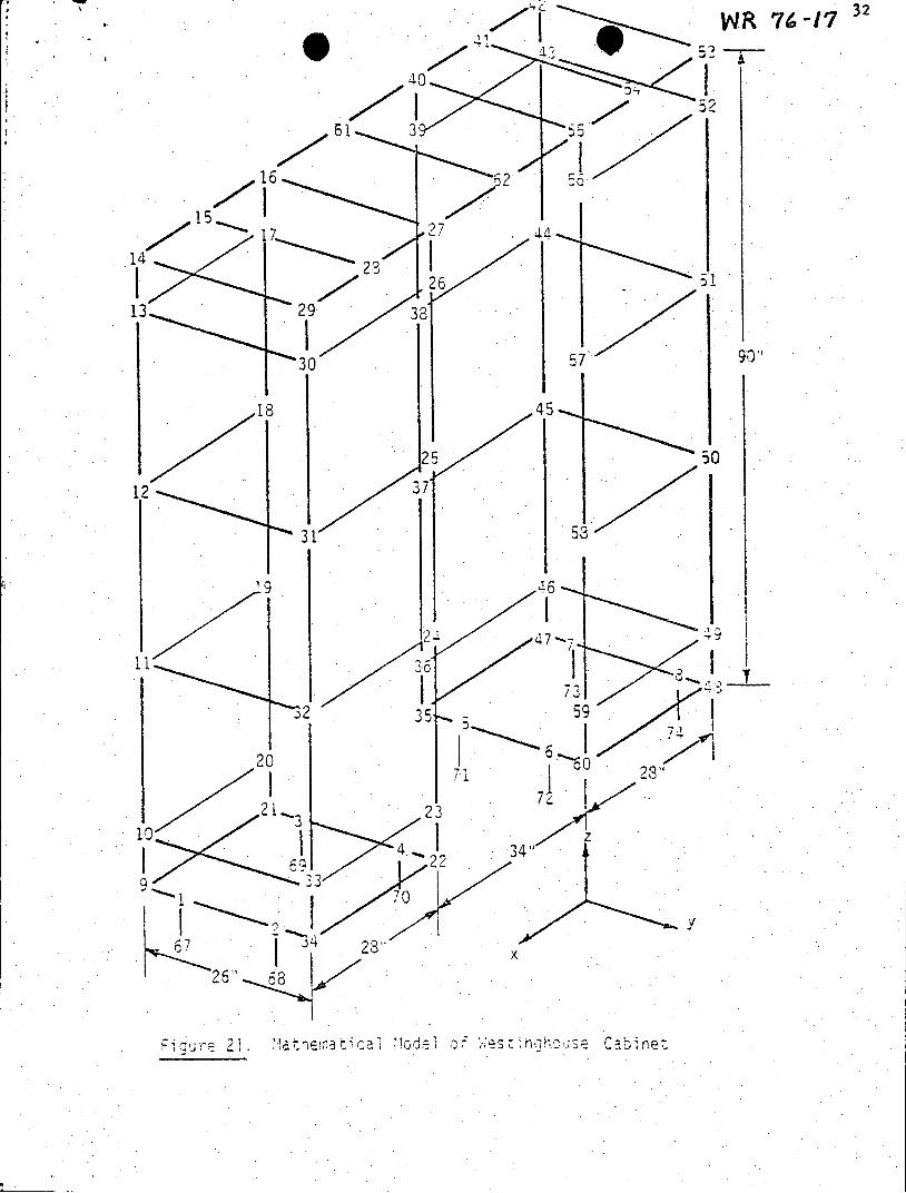
Note BB: The three types of Relay House cabinets were qualified by Wyle Laboratories using a dynamic finite element analysis employing the ANSYS computer code. The math model used for each cabinet type is shown in Figures 14a, 14b, 17, and 21 of Wyle's Report No. WR 76-17 (included at the end of these notes). The input load used is shown by the 1% damping curve of Figure 1 (horizontal and vertical floor response spectra) which is also included at the end of these notes. The load was applied at the cabinet base.
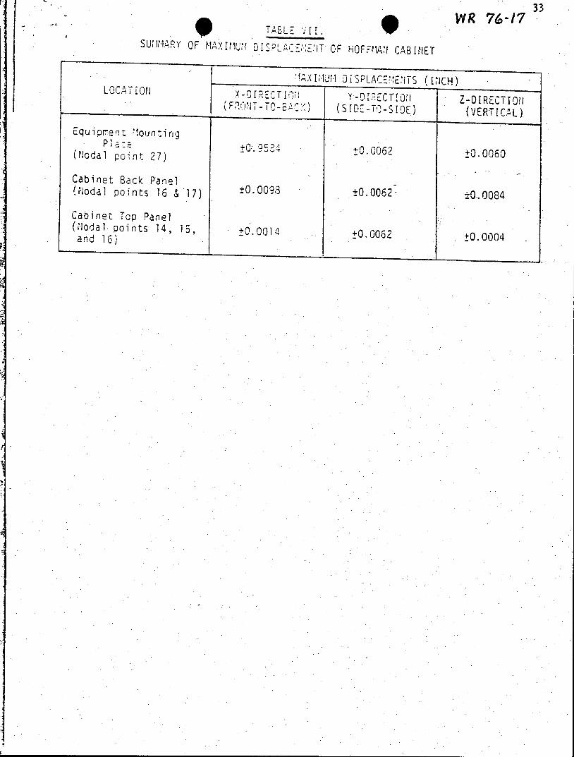
The location and magnitude of the highest stress intensity and deflection and the corresponding margins of safety are shown below.
Cabinet Type Max Stress Location Margin Deflectinn
Hoffman 249 psi bending Node 17 132% Tab1e VII (Endt. 83 psi shear of Notes)
Westinghouse 931 psi axial Element 27 20% No Significant 9919 psi bending Deflection
UEC 297 psi axial Element 32 30% No Significant 12,885 psi bending Deflection
Operability of each equipment item was verified by test. RRS for each component was determined by time history input to base of cabinet, and RRS at component location was determined.
Note CC: A static method was used for the seismic load calculations. Justification for using this method is based on the calculated rigidity, i.e., natural frequency of the systems. For the HVAC duct system, the computed natural frequency was:
fn= 45 Hz
For the roof drain piping system, the computed natural frequency was:
fn =59 Hz
Since these frequencies are greater than 33 Hz, the systems are rigid, and.the analysis method is justified. These frequencies were calculated assuming the duct and pipe as simply supported beams between supports. It should be noted that the actual acceleration used to compute the seismic loads was 0.36g which corresponds to a frequency of approximately 5.5 Hz (based on the recommended response spectra at 2% damping). For the air handling unit, no statement concerning its rigidity could be made. To account for this when employing the static analysis approach, an acceleration of 0.50g was used to determine the seismic loads. This is 1.32 times the peak of the response spectra at 2% damping.
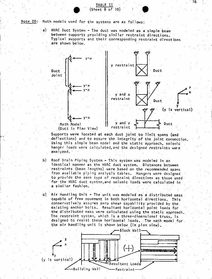
TABLE II (Sheet 8 of 10)
Note DO: Math models used for the systems are as follows:
a) HVAC Duct System - The duct was modeled as a simple beam between supports providing similar restraint directions. Typical supports and their corresponding restraint directions are shown below.
-.- y-w
y restraint t
Duct Duct Joint
4- y-x x
y and x restraint Duct
y y is vertical)
.....y -x Math Model y and z Duct (Duct In Plan View) restraint
Supports were located at each duct joint to limit spans (and deflections) and to assure the integrity of the joint connection. Using this simple beam model and the static approach, seismic hanger loads were calculated,and the designed restraints were analyzed.
b) Roof Drain Piping System - This system was modeled in an identical manner as the HVAC duct system. Distances between restraints (beam lengths) were based on the recommended spans from available piping analysis tables. Hangers were designed to provide the same type of restraint directions as those used for the HVAC duct system,and seismic loads were calculated in a similar fashion.
c) Air Handling Unit - The unit was modeled as a distributed mass capable of free movement in both horizontal directions. This conservatively assumes zero shear capability provided by the existing anchor bolts.. Resultant horizontal point loads for the distributed mass were calculated using the static approach. The restraint system, which is a three-dimensional truss, is designed to resist these horizontal loads. The math model for the air handling unit is shown below (in plan view).
Block Wall
y (y is vertical)
Resultant Load :B uild ing Wall Restraint

TABLE II (Sheet 9 of 0)
Note EE: Input seismic loads applied to the designed restraints and their points of application are shown below. All loads shown are maximum.
a) HVAC Duct System Restraints
x
y i+ Px + Pz (y is vertical) Py Py Py P P
Py = 108 lbs. Px = 182 lbs. PY 108 lbs.. Py = 191 lbs. Pz = 995 lbs.
b) Roof Drain Piping System Restraints
z
+ Px y + Px
(y is vertical) +- + Px Py -- +Pz
Px = 77 lbs. Py Py = 201 lbs. Px = 80 lbs.
Px = 40 lbs. Pz = 44 lbs. Py = 276 lbs.
c Air Handling Unit Restraint
x Px
Px = 788 lbs. -Pzl -Pz2 PzI = 188 lbs.
(y is vertical) Pz2 = 600 lbs.
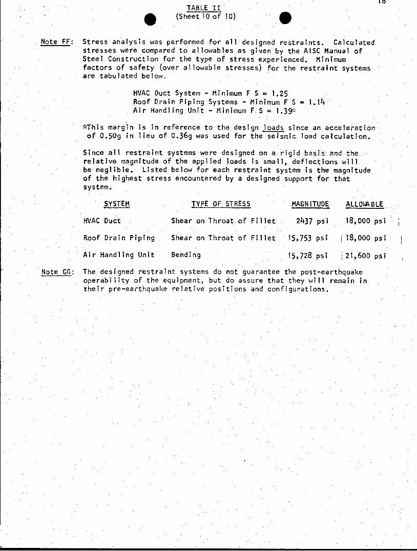
TABLE II (Sheet 10 of 10)
Note FF: Stress analysis was performed for all designed restraints. Calculated stresses were compared to allowables as given by the AISC Manual of Steel Construction for the type of stress experienced. Minimum factors of safety (over allowable stresses) for the restraint systems are tabulated below.
HVAC Duct System - Minimum F S = 1.25 Roof Drain Piping Systems - Minimum F S =1.14 Air Handling Unit - Minimum F S = 1.39,
*This margin is in reference to the design loads since an acceleration of 0.50g in lieu of 0.36g was used for the seismic load calculation.
Since all restraint systems were designed on a. rigid basis and the relative magnitude of the applied loads is small, deflections will be neglible. Listed below for each restraint system is the magnitude of the highest stress encountered by a designed support for that system.
SYSTEM TYPE OF STRESS MAGNITUDE ALLO\ABLE
HVAC Duct Shear on Throat of Fillet 2437 psi 18,000 psi
Roof Drain Piping Shear on Throat of Fillet 15,753 psi i 18,000 psi
Air Handling Unit Bending 15,728 psi 21,600 psi
Note GG: The designed restraint systems do not guarantee the post-earthquake operability of the equipment, but do assure that they will remain in their pre-earthquake relative positions and configurations.

INFORMATION FROM AGBABIAN ASSOCIATES
REPORT M-7242-2619
FIGURES 1, 3 & 5
(Refer to the Response to Question 7, Note I)
.*c
0.0.6 14.
WOU6IjwcD
16TANKfj 4tTANK ICE24
()OUTLI NE FIGURE 1. SF-6 GAS CIRCUIT BREAKER ASSEMBLY
.1r
M-7242-26 19
LOW 1-2CSsuR; 'TAwi
AWTOr,.vPTC.R
s-14 ' v-- -
(b) PRIMARY INTERNAL COMPONENTS OF EACH LOW PRESSURE TANK
FIGURE 1. (CONTINUED)
se
1* 53
47
50
1
19
41
737
es
z!34 4S
13 20 36
Z9 44
43
20
40
48
s(a) SIMPLIFIED MATH MODEL
FIGURE 3. SF-6 GAS CIRCUIT BREAKER ASSEMBLY

tM-7242-2619 2
Sc
DETAILED MATHEMATICAL MODEL BUSHING AND INTERRUPTER/SHIELD WITH SUPPORT PLATE
FIGURE 5. TANK NO. 1 OF SF-6 GAS CIRCUIl BREAKER
m-/Z -z 24
.838
.87
6!6
56
5
42
(b) PARTIAL PLOT OF THE DETAILED MATHEMATICAL MODEL TANK OUTER DIAMETER
AND BUSHING POCKET, LEFT HAND
FIGURE . (CONTINUED)

25
M-7242-2619
16
()PARTIAL PLOT OF THE DETAILED MATHEMATICAL MODEL TANK.OUTER DIAMETER WITH BUSHING POCKET, RIGHT HAND
FIGURE 5. (CONTrINUED)
1331
1771
1159 90 134
itt 107
131
1119
9 a
6111
154 6 0
47 H7
46 113S1
(d) PARTIAL PLOT OF THE DETAILED MATHEMATICAL MODEL MANHOLE SIDE OF TANK
FIGURE 5.(CONTINUED)
27
INFORMATION FROM WYLE LABORATORIES
REPORT NO. WR 76-17
FIGURES 1, l4a, 14b, 17 & 21
TABLE VII
(Refer to the Response to Question 7, Note BB)
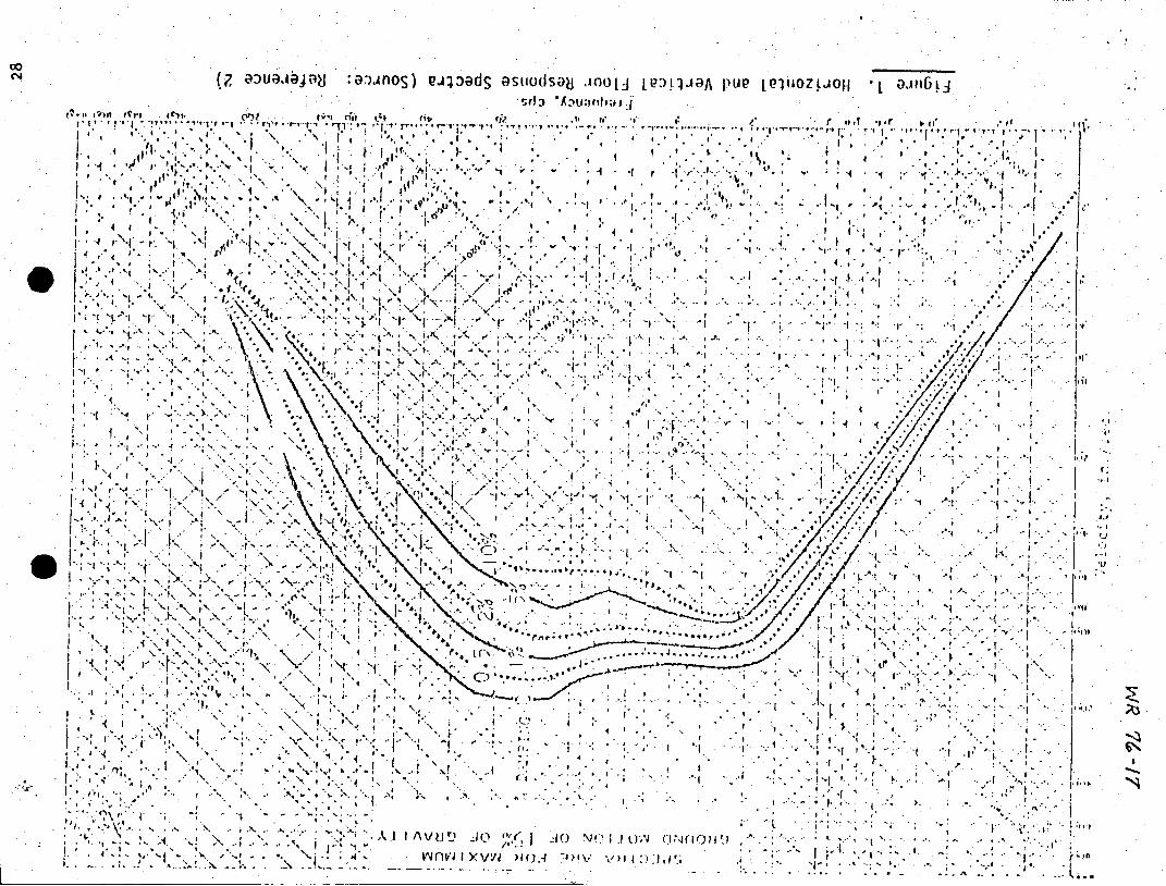
cO(7 au a Aij au :,3,-AnoS) PA:)dS asiwdsaj Aooljj PY:)LlJA Pug ijuzo *j ol6n5L.j
O f! Af*jd a ~
a I I 1 .4.
44, J
A4 I I 4 . 1A0 N 1- " Nn*i 4.., f.4 V v) 1

29
6
72" 14
39
16
17
2 7
67 72 7 73r
38
z
10
x 4 12'
.74 I 59
70 2
Figure 14a. Math Mode offan Cabinet ( SS it ninn nloal

WR 74-17
-34
3 0 N5
36
26 3 1
22 3 2 7
27
28 33 23
24
29
N N' 19
25
Z Ns -0
NN
A~ N
21
x
A. F igure 14b. Math M1-ode] of 'Mounrino 2 late, Ho"ffmain Cab inet

9R 76-17 31
14
124 31
58 90"
191
2"9 20 32 2
74
221
Fiur0 7. -it em t -l 57 n i 678' 23"5
25x
WR WO-i7
6153
162
157
901
00 57
18 45
25 50
12 37
31
19 4~6
47-
20
43
10 2 3 23 4 ~-22
67 I " 28 21
21 Ca t
33 WR 76 -1/7 TAELE ifjI.R (~l
SU IMARY OF MAxINUi 0SPLAC E;T OF HOFFMAN CABINET
X(I?1N1 DISPLACEN.ENTS (lNCH) LOCATION 0 OT
DIO 1'0Y-IECTION1 Z-01RLECTIO,1 (F2R-1 I -T S) (SIDE-T0-SIDE) (VERTICAL
Equiprent Mounting
(Nodal point 27) 0.0062 +0.0060
Cabinet Back Panel (Nodal points 16 & 17) ±0.0098 ±0.0062- ±0.0084
Cabinet Top Panel (Nodal. points 14, 15, +0.0014 t0.0062 ±0.0004 and 16)
Question 8:
In view of the size of the emergency power path, provide a discussion on detailed inservice inspection and maintenance program to ensure integrity and serviceability of the structures and equipment incorporated in the: emergency power path. Parameters required to be monitored, for example, may be tension in overhead cables or deflection of towers. Indicate your intent to incorporate the proposed inservice inspection and test frequency in the technical specifications of the three nuclear power paths.
Response:
The inservice inspection and maintenance of the Keowee and -Oconee 230kV Power Path structures and components is performed by station personnel and Transmission and Electric Installation Department personnel. This.inspection work consists of the following items:
1. Safety-related power circuit breaker are inspected on an annual basis. This inspection includes a check of mechanical linkages, contacts, gas system and. auxiliary components. PCB status is monitored by control room alarms. Non-safety-related PCB's are maintained on a two or three year basis.
2. The Keowee step-up transformer and the Oconee startup transformers are checked annually to verify conductor and insulation integrity. Alams monitor this equipment while it is in service. Voltmeters and.ammeters associated with the transformers are calibrated annually.
3. The overhead transmission lines, towers, and insulators on the Keowee to Oconee 230kV tie line are insoected by helicopter every sixty days. In addition, the towers are climbed and inspected every six months.
4. The 230kV switchyard DC system surveillance consists of daily and monthly battery cell inspection and annual battery capability testing as detailed in the Oconee Technical Specifications.
5. Metering and relaying associated with safety-related lines and buses are tested annually to ensure proper operation and calibration. Protective transmission and receiving circuits associated with certain line breaker relays are tested monthly.
6. Visual inspections of the Oconee and Keowee transformers are performed by operators on a daily basis during plant tours. Switchyard inspections would be performed in response to control room alarms or during the clearance of equipment for maintenance.
7. The 230kV Relay House air conditioning is monitored by loss of voltages and high temperature alarms in the control room.
The frequency of the maintenance not presently required by Technical Specifications may be decreased based upon the results of the current annual schedule. It is anticipated that a maximum equipment inspection interval of three years will result from this evaluation.
The foregoing is the extent of the in-service inspection and maintenance for the emergency power path. -There is no intent to incorporate this schedule in the Oconee Technical Specifications.