Embed Size (px)
Citation preview
Forschungszentrum Karlsruhe in der Helmholtz-Gemeinschaft
Wissenschaftliche Berichte
FZKA 6859
Tritium extraction from JET CFC tile samples Detritiation techniques of first wall carbon materials
used in fusion machines
N. Bekris, C. Caldwell-Nichols, L. Doerr, M. Glugla, W. Nägele, R.-D. Penzhorn,
R. Rolli, H. Ziegler
Hauptabteilung Versuchstechnik
Institut für Materialforschung
Forschungszentrum Karlsruhe GmbH, Karlsruhe 2003
Impressum der Print-Ausgabe:
Als Manuskript gedruckt Für diesen Bericht behalten wir uns alle Rechte vor
Forschungszentrum Karlsruhe GmbH
Postfach 3640, 76021 Karlsruhe
Mitglied der Hermann von Helmholtz-Gemeinschaft Deutscher Forschungszentren (HGF)
ISSN 0947-8620
ABSTRACT
Tritium in first wall materials of fusion machines is a matter of concern not only for inventory
purposes but also for safety reasons. In the first wall carbon tiles, tritium is found predominantly
in a very thin co-deposited layer and/or implanted in the surface layers. Since the tiles must
eventually be disposed off in a repository it is necessary to reduce the total tritium inventory in
the tiles down to the corresponding Low Level Waste (LLW) category. In this context, the
development of detritiation techniques for graphite and CFC tiles removed from the first wall of
fusion machines is of paramount importance. However, the experimental techniques investigated
until now are limited by the conditions and techniques permissible inside the torus. Nevertheless,
for tiles removed from the reactor more severe treatment techniques are acceptable. Working in
that direction, numerous screening tests have been carried out at the Tritium Laboratory in
Karlsruhe (TLK).
1
Tritiumextraktion aus CFC-Kachelproben von JET
Verfahren zur Detritiierung von Kohlenstoffmaterialien für die erste Wand in Fusionsanlagen
ZUSAMMENFASSUNG
Tritium in Materialien für die erste Wand von Fusionsanlagen ist ein wichtiger Aspekt nicht nur
für die Bilanzierung, sondern auch aus Gründen der Sicherheit. In den Kohlenstoffkacheln der
ersten Wand liegt Tritium vornehmlich in einer sehr dünnen koabgelagerten Schicht und/oder
implantiert in den Oberflächenschichten vor. Da die Kacheln schließlich endgelagert werden
müssen, ist das gesamte Tritiuminventar der Kacheln auf die entsprechenden Werte für schwach-
aktiven Abfall zu reduzieren. In diesem Zusammenhang ist die Entwicklung von Verfahren zur
Detritiierung von Graphit- und CFC-Kacheln der ersten Wand von Fusionsanlagen von beson-
derer Bedeutung. Die bisher untersuchten experimentellen Verfahren sind allerdings aufgrund
der Bedingungen im Torus nur von begrenztem Nutzen. Aus dem Reaktor entfernte Kacheln
können dagegen strengeren Behandlungsverfahren unterzogen werden. Dazu wurden im
Tritiumlabor in Karlsruhe (TLK) zahlreiche Screeningversuche durchgeführt.
2
3
Contents Abstract 1
Zusammenfassung 2
1. Introduction 5
2. Experimental techniques 6
2.1. The preparation of samples 6 2.2. Methods for sample characterisation 6
2.2.1. The thermogravimetry 6 2.2.2. The full combustion 6
2.3. Detritiation methods tested in the TLK 7 2.3.1. Tritium removal with an adhesive tape 7 2.3.2. Ultrasonic bath treatment 8 2.3.3. Detritiation with moist air or nitrogen 8 2.3.4. Detritiation with moist ozone 8 2.3.5. Detritiation with moist noble gases employing radio frequency (RF) heating 9 2.3.6. Detritiation by thermal desorption 9 2.3.7. Detritiation with an open flame 10
3. Results and discussion 10
3.1. Thermal analysis (TGA and DTA) 10 3.2. Ultrasonic bath treatment 12 3.3. Detritiation with moist air or nitrogen 12 3.4. Detritiation with moist ozone 13 3.5 Detritiation with moist noble gases under RF heating 14 3.6. Detritiation by thermal desorption 15 3.7. Detritiation with a flame 16
4. Evaluation of the investigated detritiation techniques 16
5. Conclusions 17
6. Acknowledgement 17
7. Literature 38

1. INTRODUCTION
In graphite tiles of the first wall of fusion machines operating with D-D or D-T plasmas,
tritium is found predominantly in a very thin co-deposited layer and/or as an implanted layer
with a thickness of few tens of micrometers. Smaller tritium concentrations are retained into the
bulk of the tiles after diffusion via to the surface connected porosity and by transgranular
diffusion. After a shut down of a fusion machine it will be necessary to reduce the tritium
concentration in the tiles to very low levels either to allow their reuse or to condition them for
final disposal. In the latter case it is important to reduce the total tritium concentration in the tiles
down to levels corresponding to those of the category of "low level waste" (12MBq/kg in UK).
To accomplish this it is necessary to develop simple, reliable, and effective detritiation
technologies allowing the conditioning of a large number of graphite and CFC tiles.
Most activities to date in the field of graphite tile detritiation have concentrated on in-situ
methods, i.e. those performed inside the reactor, having the main objective of reducing the total
in-vessel tritium inventory. Correspondingly, the work has been limited to gas-solid treatments
under conditions restricted by the parameters permissible inside of the reactor and by the current
safety requirements. Deuterium or oxygen-helium glow discharge cleaning at moderate
temperatures, disruption discharge cleaning, as well as air ventilation at moderate temperatures
have been employed as well in TFTR [i, ii] as in JET [iii]. Another recently proposed approach is
the treatment of the tile surface with an impinging laser beam under an inert gas atmosphere [iv
v]. When dealing with the tiles outside of the reactor more severe treatment techniques are
acceptable, not only because single tiles or packages can be treated, but also because no
precautions concerning the structural parts of the machine need to be taken.
In this work the main effort has been directed towards a tile treatment ex-situ with a view to
final disposal. For that reason not only gas/solid techniques have been examined, but also
methods involving liquid phase treatment of the tiles.
5
2. EXPERIMENTAL TECHNIQUES
The experimental techniques employed to investigate graphite detritiation are described
briefly below:
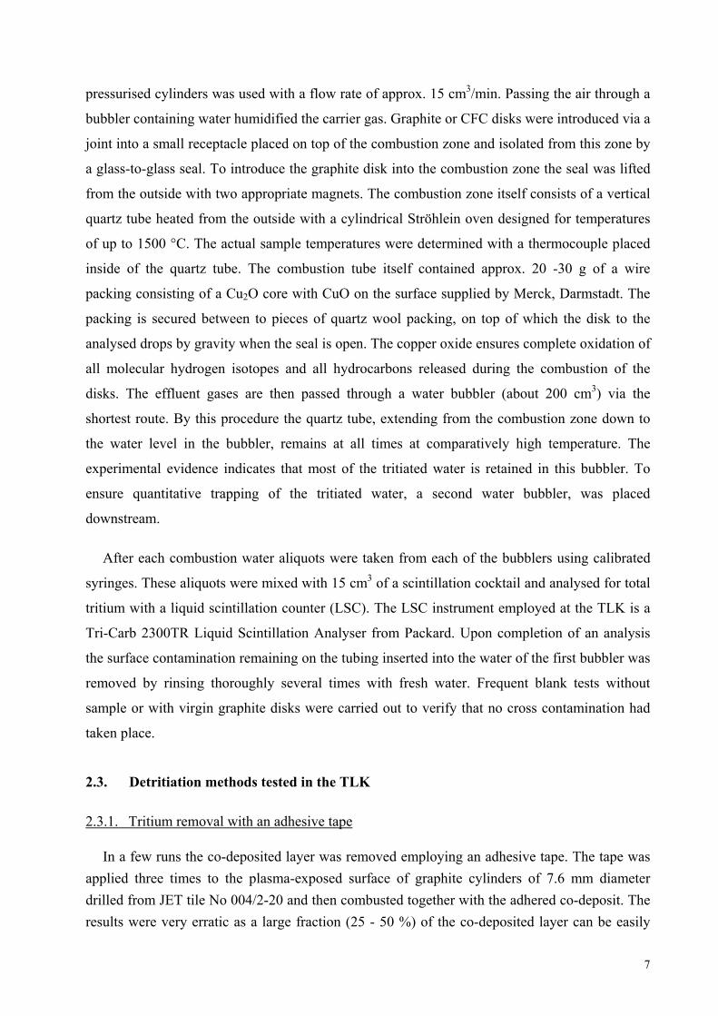
2.1. The preparation of samples
To determine the actual concentration of tritium in the bulk of a tile the face opposite to the
plasma exposed side was first cleaned with alcohol to remove all surface particles possibly
contaminated with tritium. Next, a 7.8 mm cylinder was cut starting from this face of the tile
using a fresh core drill. The cylinder produced was then retrieved and twelve, nearly equal sized
1 mm thick disks were cut from this cylinder (Fig.1 and 2).
Each disk removed from the plasma exposed side of the tile (A1 sample), was submitted to a
detritiation technique among those mentioned below and then fully oxidised with moist synthetic
air at 850°C employing a technique described in detail below, in order to determine its total
tritium content. To completely exclude cross contamination from previous tritium analyses, the
glass/quartz apparatus was thoroughly cleaned after each measurement and a full background
determination was performed to confirm it as tritium-free. The tritium released by slow and
complete combustion was collected in a water bubbler and analysed by liquid scintillation
counting.
2.2. Methods for sample characterisation
2.2.1. The thermogravimetry
For the thermogravimetric analysis (TGA) and differential thermal analysis (DTA) of graphite disks or their fragments, a Netzsch STA409 thermobalance equipped with a PU 1.851.01 power unit and a TASC414/3 controller was used. Temperatures were measured with a PtRh10-Pt thermocouple placed axially at the bottom of the ceramic sample holder. The instrument allows heating of the sample up to a temperature of 1300°C. Heat treatments were carried out either under inert gas (argon or nitrogen), air, or vacuum. In runs with samples containing tritium the exhaust gas was passed through water bubblers.
2.2.2. The full combustion
For graphite combustion, the technique proposed by Vance et al. [vi] was followed. The glass
experimental arrangement used at the TLK is shown schematically in Fig. 3. Either a stream of
laboratory air pumped with an oil-free Metal Bellows pump type MB 158E or synthetic air from
6
pressurised cylinders was used with a flow rate of approx. 15 cm3/min. Passing the air through a
bubbler containing water humidified the carrier gas. Graphite or CFC disks were introduced via a
joint into a small receptacle placed on top of the combustion zone and isolated from this zone by
a glass-to-glass seal. To introduce the graphite disk into the combustion zone the seal was lifted
from the outside with two appropriate magnets. The combustion zone itself consists of a vertical
quartz tube heated from the outside with a cylindrical Ströhlein oven designed for temperatures
of up to 1500 °C. The actual sample temperatures were determined with a thermocouple placed
inside of the quartz tube. The combustion tube itself contained approx. 20 -30 g of a wire
packing consisting of a Cu2O core with CuO on the surface supplied by Merck, Darmstadt. The
packing is secured between to pieces of quartz wool packing, on top of which the disk to the
analysed drops by gravity when the seal is open. The copper oxide ensures complete oxidation of
all molecular hydrogen isotopes and all hydrocarbons released during the combustion of the
disks. The effluent gases are then passed through a water bubbler (about 200 cm3) via the
shortest route. By this procedure the quartz tube, extending from the combustion zone down to
the water level in the bubbler, remains at all times at comparatively high temperature. The
experimental evidence indicates that most of the tritiated water is retained in this bubbler. To
ensure quantitative trapping of the tritiated water, a second water bubbler, was placed
downstream.
After each combustion water aliquots were taken from each of the bubblers using calibrated
syringes. These aliquots were mixed with 15 cm3 of a scintillation cocktail and analysed for total
tritium with a liquid scintillation counter (LSC). The LSC instrument employed at the TLK is a
Tri-Carb 2300TR Liquid Scintillation Analyser from Packard. Upon completion of an analysis
the surface contamination remaining on the tubing inserted into the water of the first bubbler was
removed by rinsing thoroughly several times with fresh water. Frequent blank tests without
sample or with virgin graphite disks were carried out to verify that no cross contamination had
taken place.
2.3. Detritiation methods tested in the TLK
2.3.1. Tritium removal with an adhesive tape
In a few runs the co-deposited layer was removed employing an adhesive tape. The tape was applied three times to the plasma-exposed surface of graphite cylinders of 7.6 mm diameter drilled from JET tile No 004/2-20 and then combusted together with the adhered co-deposit. The results were very erratic as a large fraction (25 - 50 %) of the co-deposited layer can be easily
7
removed by this procedure depending on the tape quality and the way that it is used (one or several times applied at the same surface) for the removal of tritium.
2.3.2. Ultrasonic bath treatment
The graphite or CFC disks were introduced into a 250ml Erlenmeyer flask provided with a
cap and containing either water or hydrogen peroxide and then placed into the water of an
ultrasonic bath (Super Sonorex RK103H). The disks were treated at temperatures in the range 50
- 70°C for a period of up to one hour.
2.3.3. Detritiation with moist air or nitrogen
To investigate the detritiation of graphite tiles with moist air or nitrogen, A1 disks (the first
millimetre from the surface of the plasma-exposed side of a graphite tile) were introduced into a
quartz tube inside an oven as described above.
The sample was placed inside the Vance apparatus and kept above the oven first at ambient
temperature while moist air was passed over it (10 cm3/min) for a specified period. At the same
time the oven was kept hot (>220°C) to assure complete combustion of all the released
hydrocarbons. After a specified period the same graphite disk was then introduced into the
heated zone of the oven while the temperature was increased in steps up to 400°C.
The tritium released was oxidised and collected as HTO using two consecutive bubblers, each
containing 200 ml of water, placed downstream of the reaction chamber.
The tritium remaining in the disk after the exposure to moist air to temperatures up to 400°C
was measured by full combustion of the disk.
2.3.4. Detritiation with moist ozone
To determine the tritium release achievable by treatment with ozone, a disk from the plasma-
exposed side of a graphite tile from JET was subjected to an oxygen stream containing ozone
using an experimental apparatus shown schematically in Fig. 4. Ozone was generated with a
Fischer ozone generator yielding approx. 1 g O3/h at an oxygen flow rate of 30 l/h (≈ 1.6% O3 in
O2). The oxygen/ozone stream was humidified by passing the gaseous mixture through a bubbler
containing water. Downstream of the oven the exhaust gas was passed through two consecutive
bubblers, a first one containing 50 ml water and a second one containing 20g/l potassium iodide
(KI) dissolved in water (pH = 7). The ozone content of the gas stream exiting the reactor could
be calculated from the iodine released by the reaction of ozone with potassium iodide and the
integrated gas flow.
8
In general, graphite specimens were exposed to ozone for long periods of time and heated to
temperatures in the range 25 - 220 °C. To investigate the effect of ozone, the bubbler
immediately below the reactor was replaced repeatedly by one containing fresh water. The
released tritium was measured by liquid scintillation counting.
2.3.5. Detritiation with moist noble gases employing radio frequency (RF) heating
A metal reactor with a feed through for a water-cooled RF coil was used for these
experiments. A schematic drawing of the equipment is shown in Fig. 5. The volume of the
reaction vessel was measured to be (603 ± 2) cm3. Graphite samples were placed in a quartz tube
placed axially inside of the copper RF coil. A quartz wool filter maintained the graphite
specimen at the desired position. The quartz tube was joined to the inlet stainless steel tube via a
metal/glass/quartz transition joint. The graphite itself was the susceptor for the RF heating
power. By this procedure the graphite disks could be heated very rapidly to high temperatures
measured with a pyrometer. The thermally released tritium is purged by humidified argon
(99.999 % purity in entrance) used as carrier and passes sequentially through a heated quartz
tube containing a BASF R3-11 catalyst bed (Cu2O/CuO) where it is oxidised to water and
collected downstream in 2 bubblers filled with 50ml water.
2.3.6. Detritiation by thermal desorption
The desorption studies were performed with a laboratory facility installed at the Institut fuer
Kern- und Energietechnik (IKET). The experimental set-up basically comprises a purge gas
supply and control, a high temperature stainless steel chamber containing the sample, a reduction
bed containing granulated zinc operated at approx. 390 °C and a calibrated proportional counter
for the detection of tritium. The sample chamber is heated from the outside with a controllable
tubular furnace. The zinc bed converts tritiated water to molecular gaseous tritium (HT, DT, and
traces of T2). The tubing downstream of the ionisation chamber is trace-heated to about 300 °C.
This heating contributes to minimise memory effects caused by tritiated water. Except for the
pure gas supply and control, the whole system is contained in a glove box.
The purge gas used was helium containing 0.1 vol. % hydrogen. Typical flow rates were
50 cm3 min-1. In normal operation, the sample temperature is initially increased linearly with
time (reference rate 5 K min-1) up to an end temperature of max. 1100°C, which is kept constant
for a pre-determined time.
The purge gas flow rates, the sample temperatures and the tritium activity in the purge gas,
which is derived from the count rate of the proportional counter, are continuously measured and
9
registered. The registered data are processed and evaluated with a PC data acquisition system.
The count rate is corrected for the system background as determined at the start and the end of
each run (sample at room temperature). The tritium release from the sample is obtained from the
corrected count rate and the measured flow rate. The total released activity is calculated by
integrating the release rate over the time region where a release is measurable.
2.3.7. Detritiation with an open flame
Another technique tested consisted of exposing the surface of the plasma-exposed side of a
TFTR tile to the open premixed flame of a burner supplied with acetylene and nitrous oxide. The
surface of the disk was treated for a few seconds with the hottest zone of the flame. The weight
of the disk was determined before and after the treatment. The effectiveness of the treatment was
derived from a comparison between the known mean tritium concentration of TFTR disks [vii]
and the tritium concentration measured by full combustion after brief exposure to the flame.
3. RESULTS AND DISCUSSION
3.1. Thermal analysis (TGA and DTA)
To determine optimised conditions for the combustion of graphite and of CFC specimen
thermogravimetric experiments were first carried out with blanks (untritiated samples) under
laboratory air. In a thermogravimetric analysis (TGA) the mass of the sample is recorded
continuously as a function of the temperature of the sample that increased linearly with time, in a
controlled atmosphere. A plot of mass or mass percent, as a function of the time, or the
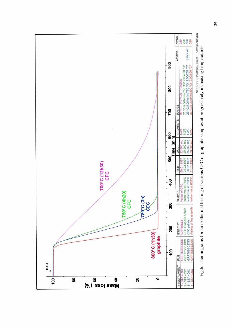
temperature, is called thermogram. Fig. 6 depicts such a thermogram showing the isothermal
combustion of a CFC and of a graphite disk at temperatures between 700°C and 800°C. From
these results it is apparent that a rapid combustion can only be achieved at very elevated
temperatures (>750°C). For instance, for the complete oxidation at 800 °C of a 34 mg graphite
sample, a total burning time of approximately two hours is required. At a temperature of only
100 °C less, the combustion time for only 22.8 mg of CFC increases significantly to more than
12 h. Of course, the combustion rates of the two specimens are different and will be discussed
hereafter.
Fig. 7 compares thermograms obtained under identical experimental conditions of burning
graphite and CFC disks. The samples were heated with a rate of 10 K min-1 up to a final
temperature of 780°C, which was thereafter held constant for about 15 hours (isothermal
treatment). From the slopes of the straight lines it was possible to estimate the weight loss rates
10
for pure graphite and CFC to be (9.5 ± 0.4) mg h-1 and (3.8 ± 0.3) mg h-1 respectively. Thus it is
apparent that graphite oxidises much more readily than CFC. The time for the complete
combustion of pieces from a disk is roughly proportional to the sample weight. Bigger the
sample more time is needed for its combustion. For instance, while the burning of 24.15 mg of
CFC is completed in about 400 min, that of 43.65 mg requires about 700 min. In both cases the
combustion rate is nearly the same, i.e. 3.8 mg/h. This suggests that the rate of combustion is
determined by the exposed surface. Grinding of the pieces would of course give rise to another
rate.
In a differential thermal analysis (DTA), the difference in temperature between the sample
and a reference material is measured as a function of the time while the sample and the reference
are submitted to a controlled temperature programme. In a DTA plot, physical or chemical
transformations are represented by characteristic peaks for each sample.
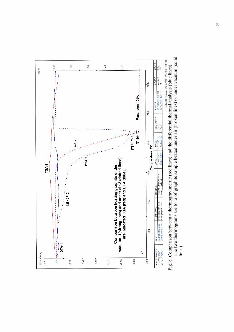
A comparison under vacuum and under air of the TGA and the DTA plots of graphite is
illustrated in Fig. 8. When a sample of 14.85 mg of virgin graphite was heated up to 1300°C
under an air atmosphere at a rate of 5 K min-1 the sample is oxidised with a progressively
increasing rate of weight loss after the temperature reached values higher than 650°C. Complete
oxidation took place after approx. 3 hours and a temperature of about 890°C. The DTA
endothermic peak observed at approx. 437°C it is probably not due to a graphite re-
crystallisation or phase transformation as such a phase transformation has been reported by
Greenwod et al for temperatures higher than 1025°C. [viii]. Therefore, we attributed the DTA
peak at temperatures below 600 °C to oxygen chemisorption reactions leading to the formation
of oxide surface complexes as it was already suggested [ix]. The broad endothermic DTA peaks
registered during the oxidation phase with maxima at 837°C and 864°C, suggests that the
oxidation of graphite to yield gaseous products takes place in more than one reaction pathway.
Potential reactions include:
2C(s) + O2(g) → 2CO(g)
C(s)+O2(g) → CO2(g)
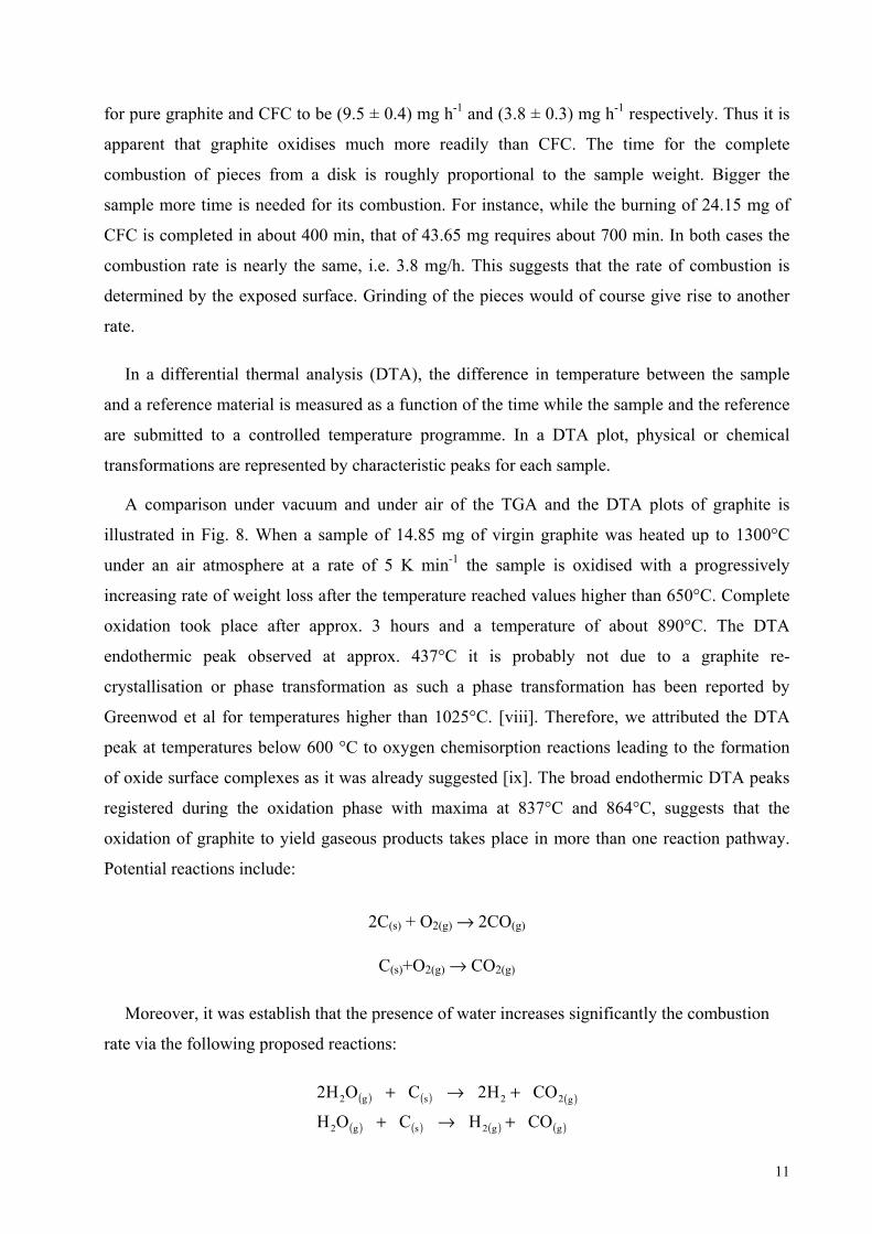
Moreover, it was establish that the presence of water increases significantly the combustion
rate via the following proposed reactions:
( ) ( ) ( )
( ) ( ) ( ) ( )gg2sg2
g22sg2
COHCOH
COH2COH2
+→+
+→+
11
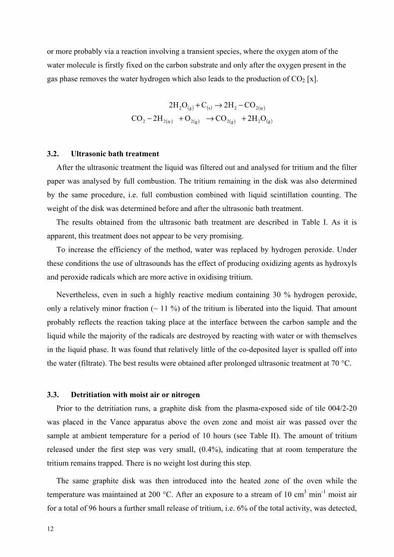
or more probably via a reaction involving a transient species, where the oxygen atom of the
water molecule is firstly fixed on the carbon substrate and only after the oxygen present in the
gas phase removes the water hydrogen which also leads to the production of CO2 [x].
( ) ( ) ( )
( ) ( ) ( ) ( )g2g2g2tr22
tr22sg2
OH2COOH2CO
COH2COH2
+→+−
−→+
3.2. Ultrasonic bath treatment
After the ultrasonic treatment the liquid was filtered out and analysed for tritium and the filter
paper was analysed by full combustion. The tritium remaining in the disk was also determined
by the same procedure, i.e. full combustion combined with liquid scintillation counting. The
weight of the disk was determined before and after the ultrasonic bath treatment.
The results obtained from the ultrasonic bath treatment are described in Table I. As it is
apparent, this treatment does not appear to be very promising.
To increase the efficiency of the method, water was replaced by hydrogen peroxide. Under
these conditions the use of ultrasounds has the effect of producing oxidizing agents as hydroxyls
and peroxide radicals which are more active in oxidising tritium.
Nevertheless, even in such a highly reactive medium containing 30 % hydrogen peroxide,
only a relatively minor fraction (~ 11 %) of the tritium is liberated into the liquid. That amount
probably reflects the reaction taking place at the interface between the carbon sample and the
liquid while the majority of the radicals are destroyed by reacting with water or with themselves
in the liquid phase. It was found that relatively little of the co-deposited layer is spalled off into
the water (filtrate). The best results were obtained after prolonged ultrasonic treatment at 70 °C.
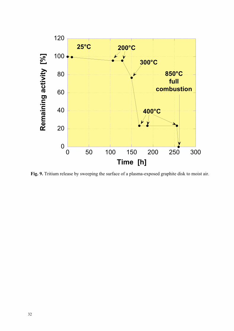
3.3. Detritiation with moist air or nitrogen
Prior to the detritiation runs, a graphite disk from the plasma-exposed side of tile 004/2-20
was placed in the Vance apparatus above the oven zone and moist air was passed over the
sample at ambient temperature for a period of 10 hours (see Table II). The amount of tritium
released under the first step was very small, (0.4%), indicating that at room temperature the
tritium remains trapped. There is no weight lost during this step.
The same graphite disk was then introduced into the heated zone of the oven while the
temperature was maintained at 200 °C. After an exposure to a stream of 10 cm3 min-1 moist air
for a total of 96 hours a further small release of tritium, i.e. 6% of the total activity, was detected,
12
the weight of the sample remaining constant. Renewed exposure of the specimen to the same
stream of moist air for another 22 hours caused no additional release of tritium but only an
apparent slight weight loss of 0.35 mg.
The same sample was then reintroduced into the apparatus and the temperature raised up to
300 °C and then to 400°C.
Table II summarises the whole experiment. As this table shows, after exposure to increasing
temperatures, the tritium release increases according to the temperature but independently of
time. The largest fraction of tritium was obtained at 400°C. The comparatively large loss of
weight observed during that step strongly suggests that letting the sample at 400°C in an
oxidative atmosphere for a long period of time (>88h) leads to a substantial combustion of
carbon without a further tritium release.
In a final run carried out at 800°C, the sample was completely combusted and the remaining
fraction of tritium collected in the bubblers. Fig. 9 illustrates the whole experiment.
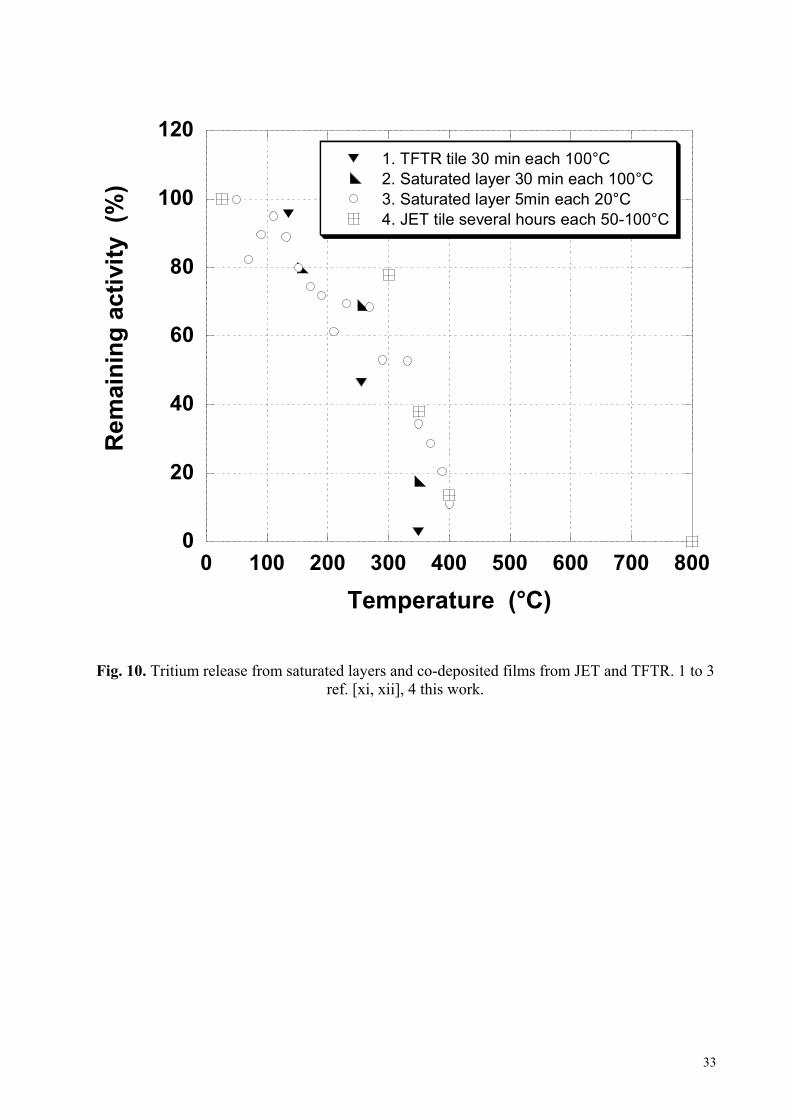
Another sample was thermally treated in a thermobalance (TGA apparatus). The specimen was
first heated under a humidified nitrogen stream at 350°C for a total of five hours and then
replaced by moist air keeping the other parameters constant. Under these conditions, 59 % of the
trapped tritium was released in the first step and only an additional 3 % after the gas exchange,
thus illustrating the importance of water regardless of the carrier gas.
Similar observations have been reported by Causey et al. [xi, xii] in their studies with co-
deposited and implanted material. Their tritium release results have been plotted in Fig. 10
together with those obtained in the above mentioned experiment.
Replacement of air by nitrogen does not appear to have a significant effect on the fraction of
released tritium. According to Wampler [xiii] and depending upon the experimental arrangement
a complete fractional release of tritium can be achieved after only 5 minutes. Thus for a rapid
and quantitative liberation of the tritium co-deposited on a tile a short exposure to moist air at a
temperature of the order of 400°C will have to be considered.
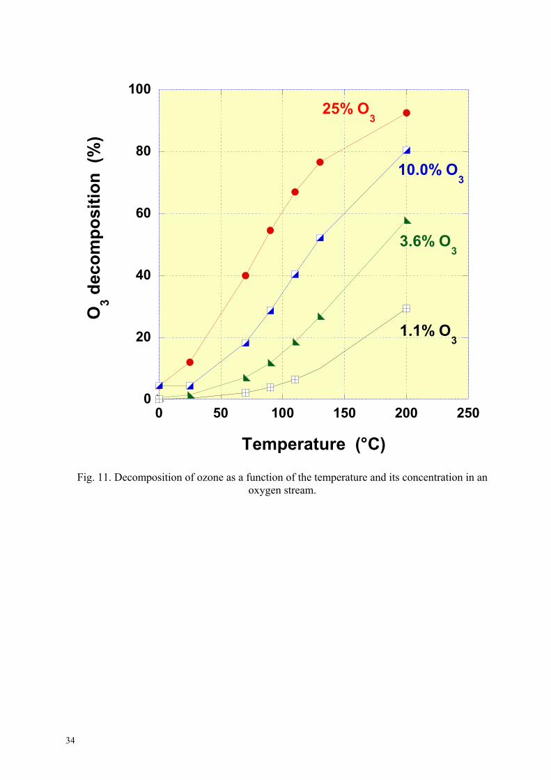
3.4. Detritiation with moist ozone
The general assumption was that ozone must be more efficient than oxygen concerning the
detritiation of plasma facing components (PFCs). This was motivated by the fact that ozone is a
powerful oxidant reagent, much stronger than oxygen. Nevertheless, passing ozone over a carbon
disc has produced only minor releases of tritium (max 6%). This can be attributed to two facts,
firstly the presence of water hinders the ozone reaction with the sample; e.g. ozone reacts
preferentially with water rather than the sample. Secondly, passing ozone through a heated
13
quartz tube decomposes it thermally according to the modified Jahn atomic mechanism [xiv, xv,
xvi]:
M + O3 M+ O→12 + O. (to equilibrium)
←2
O. +
where M may be O2 or O3.
Using previous experimental r
calculate the decomposition of o
Fig. 11 shows the ozone decomp
is raised, the fraction of ozone
smaller. Curiously, working with
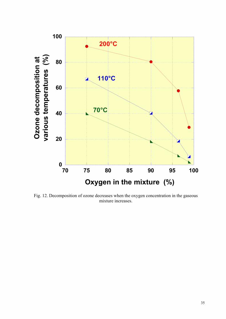
Indeed, as it is illustrated in Fig
oxygen concentration is increasin
experimental conditions as our
decomposition is also independen
The small release of tritium
exchange with moisture or some
issue.
3.5 Detritiation with moist n
Under the assumption that the
section 3.3) some tests were car
oxygen has the potential advan
therefore without damaging the
carbon oxides in the exhaust strea
In these experiments the sp
stainless steel apparatus (Fig.5). I
exposed side of cylinder n°35 dri
inside the apparatus. The whole
saturated with moisture was intro
15 cm3 min - 1 over a period of 65
of the tritium was released under
14
O3 2O→32 (rate determining)
esults obtained by Axworthy and Benson [xvii] it is possible to
zone in respect to the temperature and its dilution in oxygen.
osition as a function of temperature. Clearly, as the temperature
available for reaction with the co-deposited layer becomes
bigger amounts of ozone will not increase the reaction yield.
. 12 the ozone decomposition is markedly decreasing as the
g. Moreover, as it was already pointed out, under the dynamic
s (ozone is flowing and not in a static atmosphere) the
t of the concentration of the added nitrogen [xviii].
observed could be caused by ozone, left after decomposition,
other oxidation mechanism. More work is needed to clarify this
oble gases under RF heating
type of carrier gas for the moisture is of minor importance (see
ried out using argon as carrier gas. The prospect of avoiding
tage of a tritium release without graphite combustion and
tile. In addition, the need to deal with tritium contaminated
m is avoided.
ecimens were heated by radio-frequency (RF) heating in a
n the first run, an A1 disk (59.50 mg) obtained from the plasma
lled from tile 004/2-20 was introduced into the axial quartz tube
reactor was then evacuated to remove oxygen. Then argon
duced into the reactor and the gas flowed through at a rate of
h. The temperature was measured pyrometrically. Only 0.3 %
these conditions. The disk was then heated very rapidly by RF
heating up to 850°C. The fraction of released tritium with time was determined by periodically
changing the bubblers, initially after 30 min and then after more prolonged periods of time (see
Table III). Of the total activity in the disk, not more than 96.3% is liberated even after 24 hours
at 850°C when moist argon is used as carrier gas.
When the reactor was opened it was observed that a very thin disk (weight 0.25 mg) had
spalled off from the main disk (Fig 13). The registered weight loss of the thick disk was
determined to be 6.7 mg indicating that a portion of the thin disk had been consumed. To
determine the tritium content, both disks were combusted separately. The measured tritium
concentrations in the two disks have been tabulated in Table IV.
It is seen that all of the remaining activity is concentrated in the thin disk. From this it could
be concluded that the spalled off disk actually constitutes the co-deposited layer. It appears that
under the prevailing conditions 850°C is sufficient to remove all the bulk tritium but not all of
the tritium in the co-deposited layer. This supports previous suggestions that hydrogen in the co-
deposited layer is strongly bound in the form of covalent chemical bonds [xiii].
3.6. Detritiation by thermal desorption
To improve the signal to background ratio in this thermal desorption investigation, a low purge of He with 1% H2 flow rate of 10 standard cm3 min-1 was used. To study the thermal release the sample temperature was raised up to 1100 °C employing a rate of 5 °C min-1. Altogether five disks from JET tile No 004/2-20 were heated under isochronal conditions and the results summarised in Table V. Only the disks obtained from the plasma-exposed side of the tile showed a significant tritium content of approximately 18-21 kBq per cm2 of plasma-exposed surface. All other disks yielded tritium concentrations that were below the detection limit, i.e. 1.10 kBq cm-2. The sample temperature, the tritium release rate and the total tritium released from the A1 disk of cylinders 5 is depicted in Fig. 14. The two release curves are essentially similar, i.e. the release commences at about 700 °C, and the release rate reaches a maximum at approx. 850 °C. At still higher temperatures the release rate decreases rapidly. When a maximum temperature of about 1100 °C is attained the release rate drops to nearly zero, indicating that most of the tritium has gassed off. Similar observations have been reported by Sawicki et al. [xix]. The higher peak release rates are possibly caused by the higher heating rates employed by these investigators. They observed that neither a shift nor a broadening of the tritium depth profile could be detected within the accuracy of the measurements when graphite specimens containing tritium ion implanted at energies between 10 and 50 keV were heated to very high temperatures, i.e. ≤ 1700 K. This should be of significant importance as it suggests that tritium did not diffuse into the bulk of the samples but still needs to be confirmed with tiles recovered from a D-T operated machine.
15
Concerning the detritiation of graphite, the release data described above imply that only at temperatures above 700 °C will it be possible to liberate the tritium from the tiles via heating in a He + 0.1 % H2 purge gas. 3.7. Detritiation with a flame
In a few runs, disks obtained from the plasma-exposed side of a TFTR tile were treated with
an open flame for a few seconds and the remaining tritium measured by the full combustion
technique. It was observed that with this hard but short treatment more than 98 % of the tritium
can be liberated within a very short time. Thus, this treatment can be considered as highly
promising for the detritiation of tiles before final disposal.
Conceivably, the tiles could be passed under a flame crown or exposed to a rectangular burner
in an appropriate closed oven while continuously sweeping with an appropriate moist gas (or gas
mixture) stream. A heated copper oxide bed downstream could ensure that all tritiated species
and carbon monoxide are quantitatively oxidised to water and carbon dioxide. Water could be
trapped very efficiently in a type 3A zeolite molecular sieve bed which do as not essentially
retain carbon dioxide.
4. EVALUATION OF THE INVESTIGATED DETRITIATION TECHNIQUES
The ultimate goal of this waste conditioning investigation is an assessment of the effort
needed to achieve the "solid low level radioactive waste category" for the graphite tiles of JET.
In the UK, solid waste having a specific activity greater than 0.4 Bq g-1 and below 12 MBq kg-1
of non-alpha emitting radionuclides falls under this category [xx].
The most promising techniques appear to be:
• Abrasive removal of the co-deposited layer from a tile with a metal brush or an abrasive
paper
• Treatment of a whole tile with humidified air at temperatures of 400°C or above
• Short treatment of the plasma-exposed side of a tile with an open flame or alternative
flash heating procedures
In addition, the exposure of a RF heated tile to a humidified noble gas has also yielded
encouraging results. These and other techniques, such the use of an argon torch [xxi], will now
be tested in the near future on whole tiles or large fragments of them.
Table VI summarises the advantages and shortcomings of the various detriation techniques
used during this work.
16
5. CONCLUSIONS
Graphite tiles used in fusion devices such as JET operated with a D-D or a D-T plasma
contain tritium. In graphite tiles most of the tritium (about 99 %) is found in a thin layer of less
than 50 µm on the plasma-exposed side of the tile. The rest of the tritium (about 1 %) is evenly
distributed within the bulk of the tile. For CFC tiles a large fraction of the tritium is trapped in
the bulk. The detritiation techniques described in the paper (except full combustion) are almost
exclusively dedicated to the detritiation of the surface co-deposited layer.
Treatment of plasma-exposed graphite in an ultrasonic bath containing water or hydrogen
peroxide proved to be a rather ineffective detritiation method.
A humidified ozone/oxygen stream causes only minor liberation of tritium co-deposited with
carbon at temperatures in the range 25-200°C. The ozone decomposition rates increasing with
increasing temperatures (nearly complete at temperatures of about 200°C) constitute the limiting
factor for this technique.
In laboratory experiments a sizeable fraction of the tritium in the co-deposited layer of tile
sample is released by heating up to about 400°C under a stream of moist synthetic air or
nitrogen. The release of tritium is predominantly determined by the temperature and to a lesser
extent by the duration of the heating.
With RF heating at 850°C under a humidified noble gas stream it is possible to achieve high
tritium decontamination factors. Further research shall uncover the full potential of the
technique.
The quick treatment of the plasma-exposed side of a graphite specimen with an open
acetylene flame proved to be very successful. Alternative flush heating procedures should also
be explored, which may have reduced hazards associated with them.
6. ACKNOWLEDGEMENT
This work was performed in the framework of the Nuclear Fusion Project of the
Forschungszentrum Karlsruhe and is supported by the EU within the European Fusion Program.
17
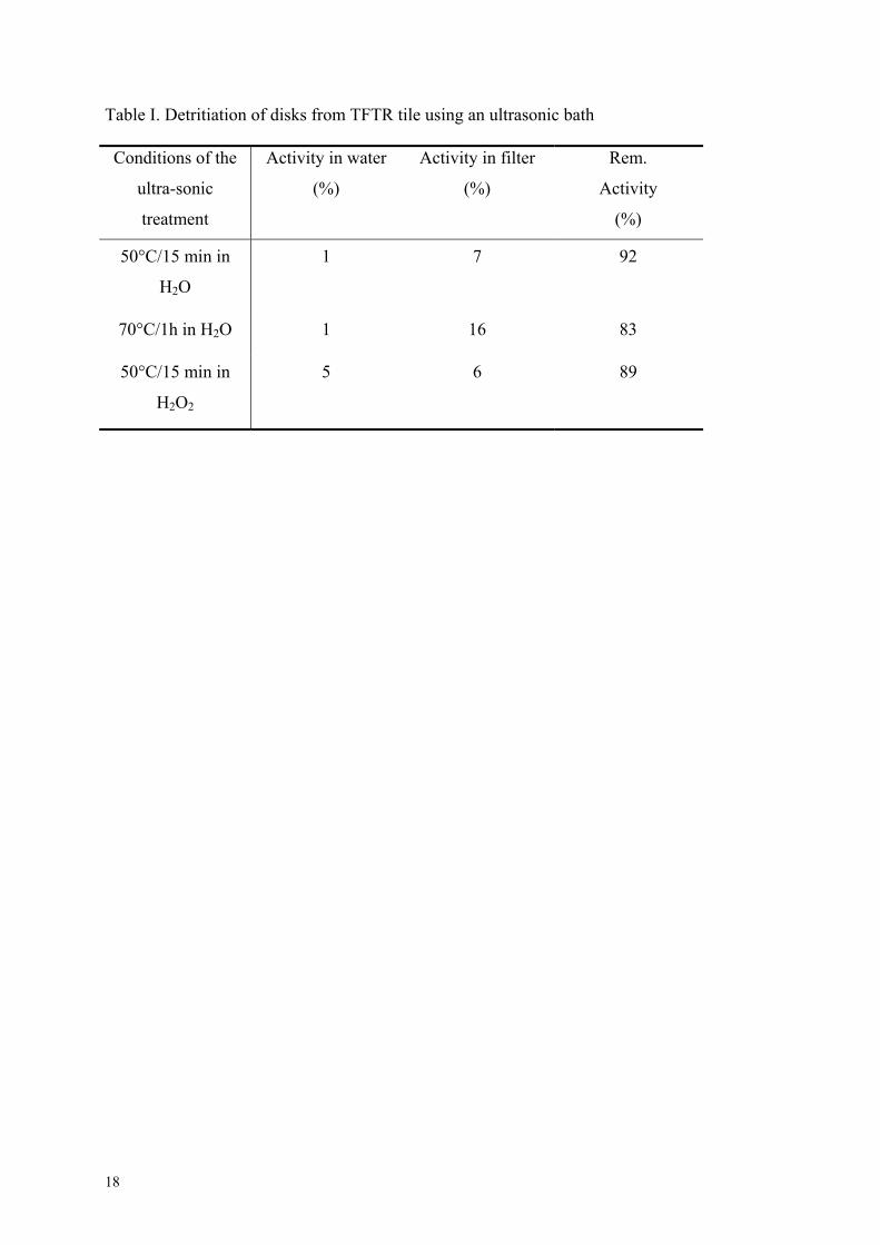
Table I. Detritiation of disks from TFTR tile using an ultrasonic bath Conditions of the
ultra-sonic
treatment
Activity in water
(%)
Activity in filter
(%)
Rem.
Activity
(%)
50°C/15 min in
H2O
1 7 92
70°C/1h in H2O 1 16 83
50°C/15 min in
H2O2
5 6 89
18
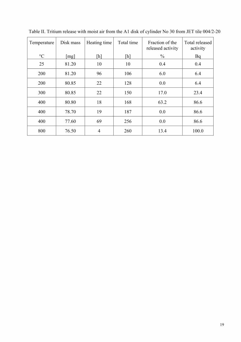
Table II. Tritium release with moist air from the A1 disk of cylinder No 30 from JET tile 004/2-20
Temperature
°C
Disk mass
[mg]
Heating time
[h]
Total time
[h]
Fraction of the released activity
%
Total released activity
Bq 25 81.20 10 10 0.4 0.4
200 81.20 96 106 6.0 6.4
200 80.85 22 128 0.0 6.4
300 80.85 22 150 17.0 23.4
400 80.80 18 168 63.2 86.6
400 78.70 19 187 0.0 86.6
400 77.60 69 256 0.0 86.6
800 76.50 4 260 13.4 100.0
19
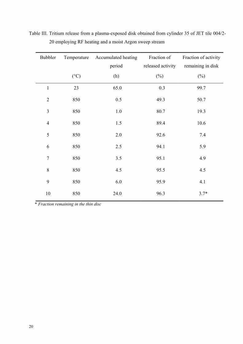
Table III. Tritium release from a plasma-exposed disk obtained from cylinder 35 of JET tile 004/2-
20 employing RF heating and a moist Argon sweep stream
Bubbler Temperature
(°C)
Accumulated heating
period
(h)
Fraction of
released activity
(%)
Fraction of activity
remaining in disk
(%)
1 23 65.0 0.3 99.7
2 850 0.5 49.3 50.7
3 850 1.0 80.7 19.3
4 850 1.5 89.4 10.6
5 850 2.0 92.6 7.4
6 850 2.5 94.1 5.9
7 850 3.5 95.1 4.9
8 850 4.5 95.5 4.5
9 850 6.0 95.9 4.1
10 850 24.0 96.3 3.7*
* Fraction remaining in the thin disc
20
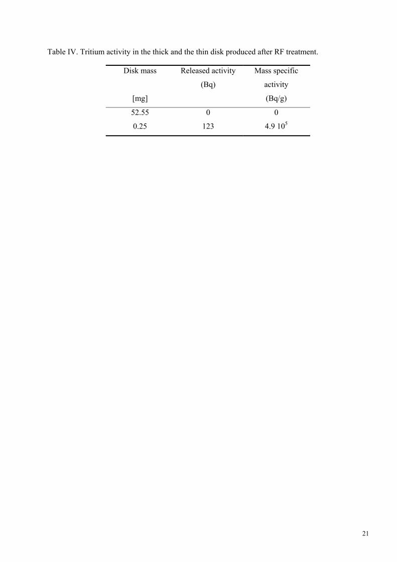
Table IV. Tritium activity in the thick and the thin disk produced after RF treatment.
Disk mass
[mg]
Released activity
(Bq)
Mass specific
activity
(Bq/g)
52.55 0 0
0.25 123 4.9 105
21
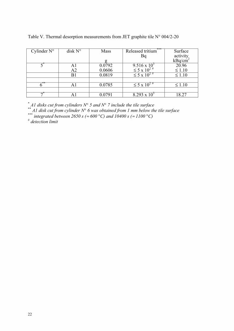
Table V. Thermal desorption measurements from JET graphite tile N° 004/2-20
Cylinder N° disk N° Mass g
Released tritium*** Bq
Surface activity kBq/cm2
5* A1 0.0792 9.516 x 10³ 20.96 A2 0.0606 ≤ 5 x 10² # ≤ 1.10 B1 0.0819 ≤ 5 x 10² # ≤ 1.10
6** A1 0.0785 ≤ 5 x 10² # ≤ 1.10
7* A1 0.0791 8.293 x 10³ 18.27 * A1 disks cut from cylinders N° 5 and N° 7 include the tile surface ** A1 disk cut from cylinder N° 6 was obtained from 1 mm below the tile surface *** integrated between 2650 s (≈ 600 °C) and 10400 s (≈ 1100 °C) # detection limit
22
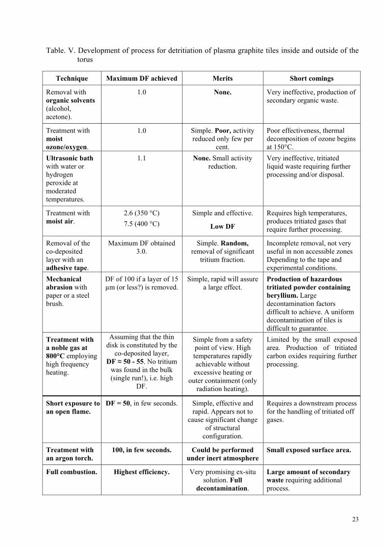
Table. V. Development of process for detritiation of plasma graphite tiles inside and outside of the torus
Technique Maximum DF achieved Merits Short comings
Removal with organic solvents (alcohol, acetone).
1.0 None. Very ineffective, production of secondary organic waste.
Treatment with moist ozone/oxygen.
1.0 Simple. Poor, activity reduced only few per
cent.
Poor effectiveness, thermal decomposition of ozone begins at 150°C.
Ultrasonic bath with water or hydrogen peroxide at moderated temperatures.
1.1 None. Small activity reduction.
Very ineffective, tritiated liquid waste requiring further processing and/or disposal.
Treatment with moist air.
2.6 (350 °C) 7.5 (400 °C)
Simple and effective.
Low DF
Requires high temperatures, produces tritiated gases that require further processing.
Removal of the co-deposited layer with an adhesive tape.
Maximum DF obtained 3.0.
Simple. Random, removal of significant
tritium fraction.
Incomplete removal, not very useful in non accessible zones Depending to the tape and experimental conditions.
Mechanical abrasion with paper or a steel brush.
DF of 100 if a layer of 15 µm (or less?) is removed.
Simple, rapid will assure a large effect.
Production of hazardous tritiated powder containing beryllium. Large decontamination factors difficult to achieve. A uniform decontamination of tiles is difficult to guarantee.
Treatment with a noble gas at 800°C employing high frequency heating.
Assuming that the thin disk is constituted by the
co-deposited layer, DF ≈ 50 - 55. No tritium
was found in the bulk (single run!), i.e. high
DF.
Simple from a safety point of view. High temperatures rapidly achievable without
excessive heating or outer containment (only
radiation heating).
Limited by the small exposed area. Production of tritiated carbon oxides requiring further processing.
Short exposure to an open flame.
DF = 50, in few seconds. Simple, effective and rapid. Appears not to
cause significant change of structural
configuration.
Requires a downstream process for the handling of tritiated off gases.
Treatment with an argon torch.
100, in few seconds. Could be performed under inert atmosphere
Small exposed surface area.
Full combustion. Highest efficiency. Very promising ex-situ solution. Full
decontamination.
Large amount of secondary waste requiring additional process.
23
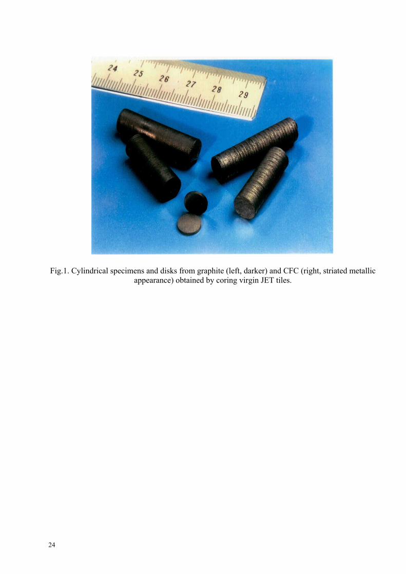
Fig.1. Cylindrical specimens and disks from graphite (left, darker) and CFC (right, striated metallic appearance) obtained by coring virgin JET tiles.
24
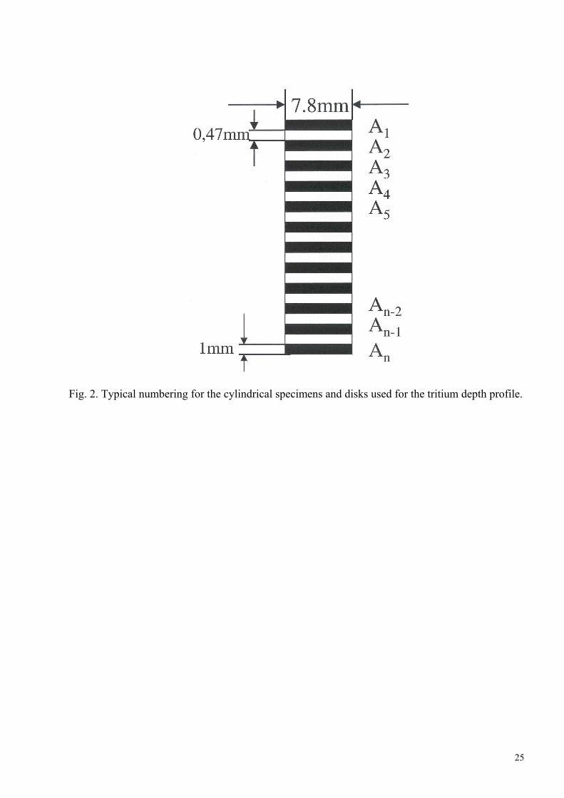
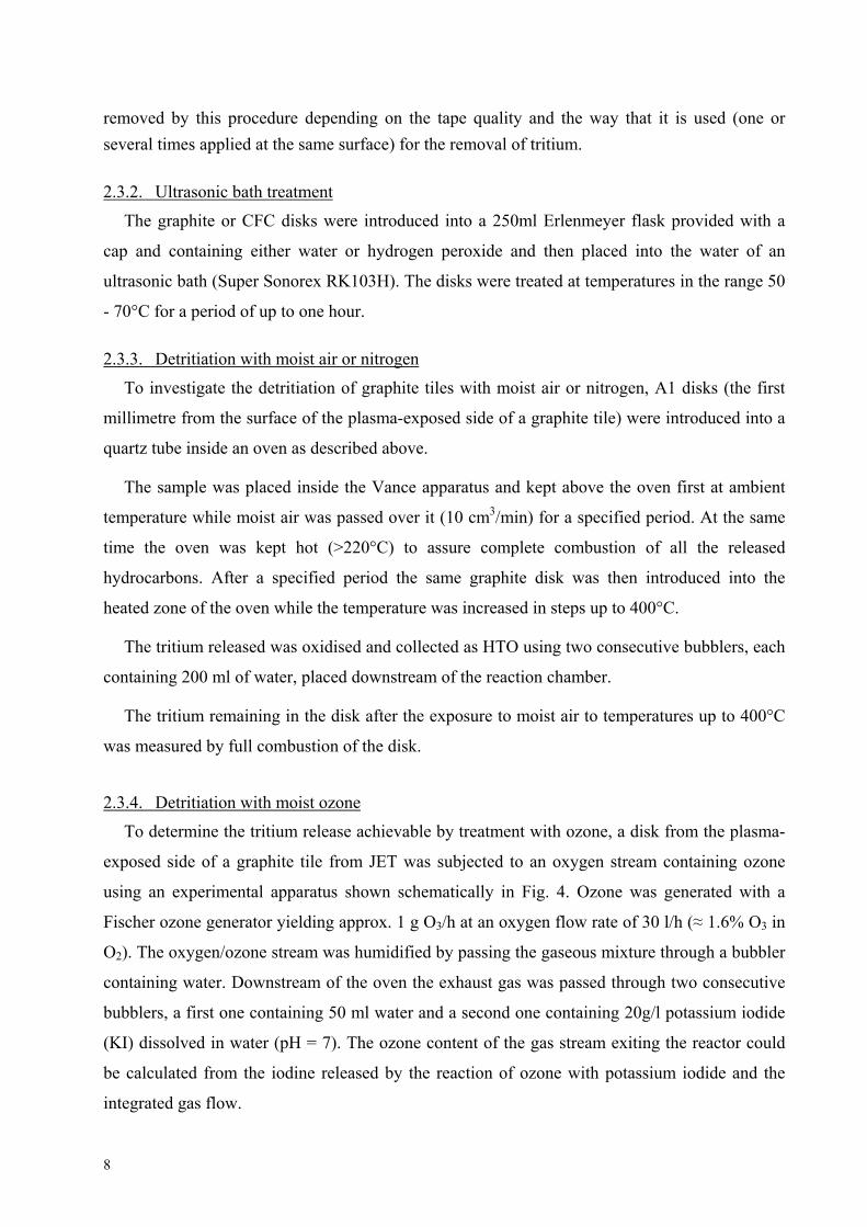
Fig. 2. Typical numbering for the cylindrical specimens and disks used for the tritium depth profile.
25
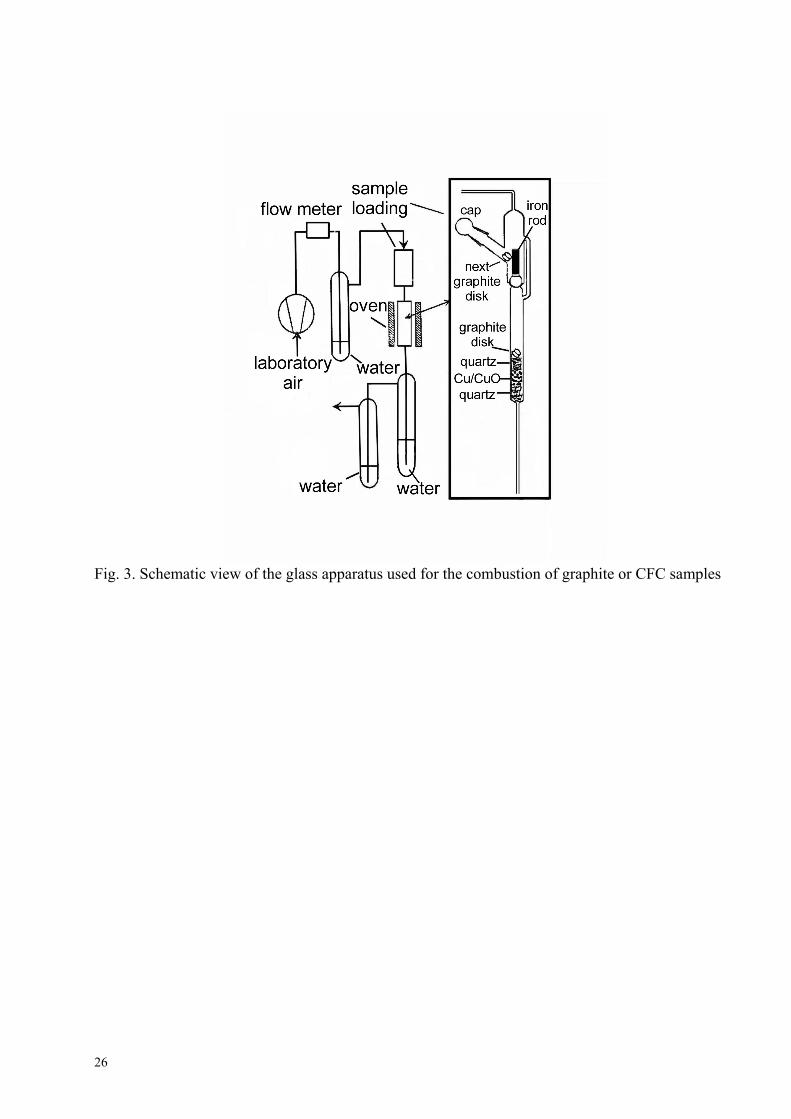
Fig. 3. Schematic view of the glass apparatus used for the combustion of graphite or CFC samples
26
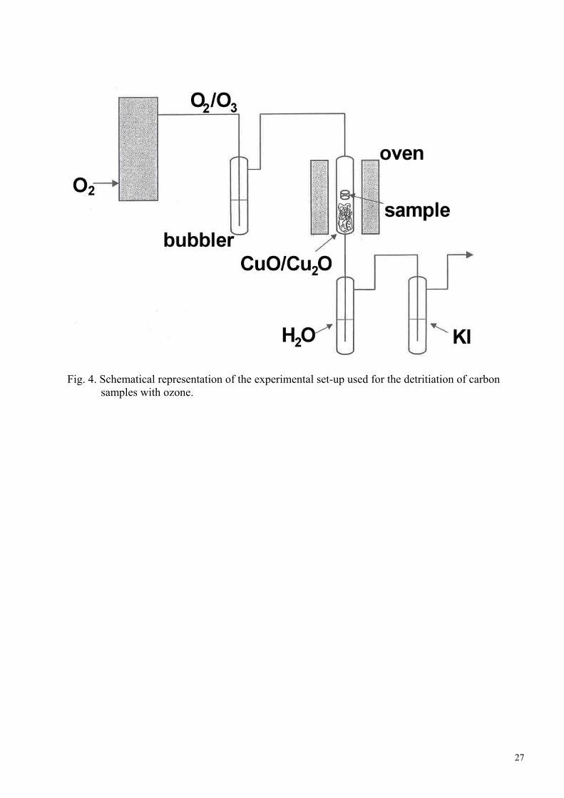
Fig. 4. Schematical representation of the experimental set-up used for the detritiation of carbon
samples with ozone.
27
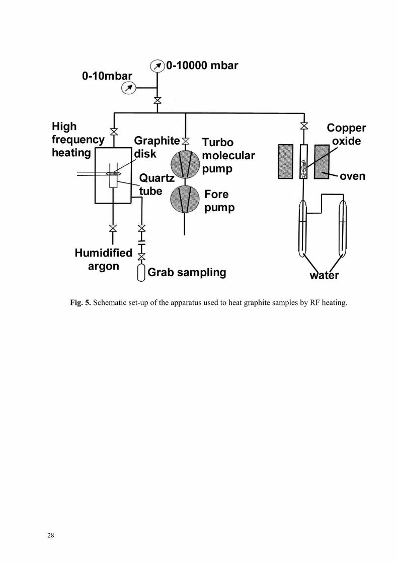
Fig. 5. Schematic set-up of the apparatus used to heat graphite samples by RF heating.
28
Fi
g.6.
The
rmog
ram
s for
an
isot
herm
al h
eatin
g of
var
ious
CFC
or g
raph
ite sa
mpl
es a
t pro
gres
sive
ly in
crea
sing
tem
pera
ture
s
29

Fi
g. 7
. Iso
ther
mal
hea
ting
of C
FC o
r gra
phite
sam
ples
at 7
80°C
und
er a
ir. F
or e
ach
sam
ple
is a
lso
give
n th
e tim
e ne
eded
for t
he fu
ll co
mbu
stio
n.
30
Fi
g. 8
. Com
paris
on b
etw
een
a th
erm
ogra
vim
etric
(red
line
s) a
nd th
e di
ffer
entia
l the
rmal
ana
lysi
s (bl
ue li
nes)
. Th
e tw
o th
erm
ogra
ms a
re fo
r a o
f gra
phite
sam
ple
heat
ed u
nder
air
(bro
ken
lines
) or u
nder
vac
uum
(sol
id
lines
)
31
0
20
40
60
80
100
120
0 50 100 150 200 250 300
Rem
aini
ng a
ctiv
ity [
%]
Time [h]
25°C 200°C
300°C
400°C
850°Cfull
combustion
Fig. 9. Tritium release by sweeping the surface of a plasma-exposed graphite disk to moist air.
32
0
20
40
60
80
100
120
0 100 200 300 400 500 600 700 800
1. TFTR tile 30 min each 100°C2. Saturated layer 30 min each 100°C3. Saturated layer 5min each 20°C 4. JET tile several hours each 50-100°C
Rem
aini
ng a
ctiv
ity (
%)
Temperature (°C)
Fig. 10. Tritium release from saturated layers and co-deposited films from JET and TFTR. 1 to 3
ref. [xi, xii], 4 this work.
33
0
20
40
60
80
100
0 50 100 150 200 250
O3 d
ecom
posi
tion
(%)
Temperature (°C)
25% O3
1.1% O3
3.6% O3
10.0% O3
Fig. 11. Decomposition of ozone as a function of the temperature and its concentration in an oxygen stream.
34
0
20
40
60
80
100
70 75 80 85 90 95 100
Ozo
ne d
ecom
posi
tion
atva
rious
tem
pera
ture
s (%
)
Oxygen in the mixture (%)
200°C
110°C
70°C
Fig. 12. Decomposition of ozone decreases when the oxygen concentration in the gaseous mixture increases.
35
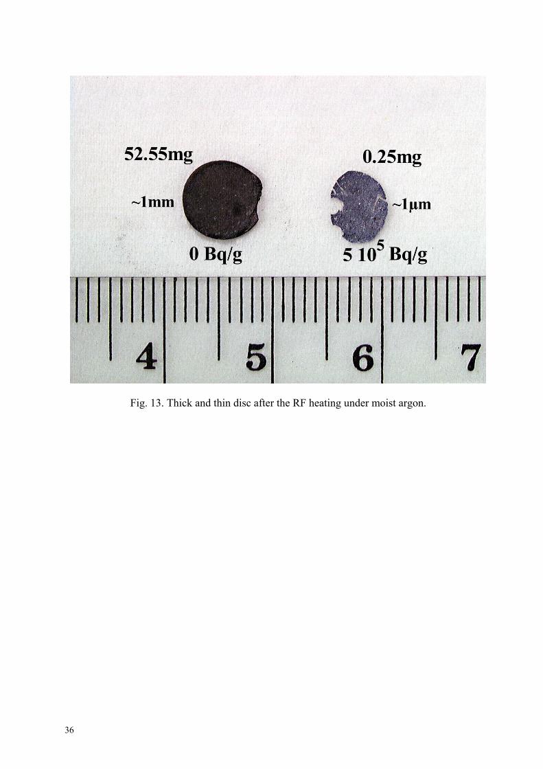
Fig. 13. Thick and thin disc after the RF heating under moist argon.
36
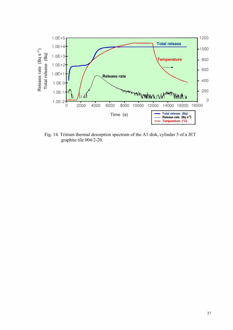
Fig. 14. Tritium thermal desorption spectrum of the A1 disk, cylinder 5 of a JET graphite tile 004/2-20.
37
7. LITERATURE
[i] D. Mueller, W. Blanchard, J. Collins, J. Hosea, J. Kamperschroer, P. H. LaMarche, A. Nagy,
D. K. Owens and C. H. Skinner. Tritium removal from TFTR. J. Nucl. Mater., 241-243, (1997), 897.
[ii] C.H. Skinner, C.A. Gentile, K.M. Young, J.P. Coad, J.T. Hogan, R.-D. Penzhorn, N Bekris. Long-term Tritium Trapping in TFTR and JET. 28th EPS Conference on Controlled Fusion and Plasma Physics, Madeira, Portugal, 18-22nd June, 2001, Europhysics Conference Absracts, Vol. 25A (2001) 1621-1624
[iii] P. Andrew, P. D. Brennan, J. P. Coad, J. Ehrenberg, M. Gadeberg, A. Gibson, D. L. Hillis, J. How, O. N. Jarvis, H. Jensen R. Laesser et al. Tritium retention and clean-up in JET. Fus. Eng. & Des., 47 (1999) 233.
[iv] C. H. Skinner, C. A. Gentile, A. Carpe, G. Guttadora, S. Langish, K. M. Young, W. M. Shu, H. Nakamura. Tritium removal from codeposits on carbon tiles by a scanning laser. J. Nucl. Mater. 301, 2002, 98-107.
[v] C.H. Skinner, N Bekris, C.A. Gentile, M. Glugla. Tritium removal from JET and TFTR tiles by a scanning laser. J. Nucl. Mat. 313-316 (2003) 499-503.
[vi] D.E.Vance, M.E. Smith, G.R.Waterbury. Quantitative determination of tritium in metals and oxides. LA-7716 UC, report, April 1979.
[vii] R.-D. Penzhorn, N. Bekris, W. Hellriegel, H. -E. Noppel, W. Nägele, H. Ziegler, R. Rolli, H. Werle,A. Haigh, A. Peacock. Tritium profiles in tiles from the first wall of fusion machines and techniques for their detritiation. J. Nucl. Mat. 279 (2000) 139-152
[viii] Greenwood, A.Earnshaw. Chemistry of the Elements, Pergamon Press, 1st ed. 1984, pg.303. [ix] Gmelins Hanbuch der Chemie, Kohlenstoff, Teil B, System N°14, Verlag Chemie GmbH,
Weiheim, Bergstrasse, pg.796. [x] J.W. Mellor, Inorganic and Theoretical Chemistry, Longmans, Green and Co., vol. V (1955)
p. 811. [xi] R.A.Causey, W.L.Chrisman, W.L.Hsu, R.Anderl, B.Wishard. Tritium release from a
codeposited layer of carbon and tritium during air exposure. J.Vac. Sci. Technol. A7(1989) 1078.
[xii] R.A.Causey, W.R.Wampler, D.Walsh. Comparison of the thermal stability of the codeposited carbon/hydrogen layer to that of the saturated implant layer. J. Nucl. Mater. 176&177 (1990) 987-991.
[xiii] W.R. Wampler, B.L.Doyle, R.A.Causey, K.Wilson. Trapping of Deuterium at damage in graphite. J.Nucl. Mater. 176&177(1990) 983.
[xiv] Jahn, Z. Anorg. Chem., 48, (1905), 260. [xv] O.Wulf, R.C.Tolman, The thermal decomposition of Ozone. III. The temperature coefficient
of reaction rate. J. Amer. Chem. Soc. 49, (1927) 1650-1664. [xvi] S.Benson, A.Axworthy Jr. Mechanism of the gas phase thermal decomposition of ozone. J.
Chem. Phys. 26, (1957) 1718-1726. [xvii] Ozone chemistry and technology. Proceedings of the international ozone conference held
in Chicago, IL, November 1956. Washington, D.C.: Am.Chem.Soc. (1959). VI, 465 pg. 388. (Advances in chemistry series. Nr 21.).
[xviii] D.Garvin. The oxidation of carbon monoxide in the presence of ozone. J. Amer. Chem. Soc. 76, (1954) 1523-1527.
[xix] J.A.Sawicki, J.Roth, L.M.Howe. Thermal release of tritium implanted in graphite studies by T(d,a)n nuclear reaction depth profiling analysis. J. Nucl. Materials 162-164, (1989), 1019.
38
xx] A. D. Haigh, R. Middleton and G. Newbert. Waste management aspects of the DTE1 and
RTE campaigns. Fus. Eng. & Des., 47, (1999), 285-299. [xxi] R.-D. Penzhorn, N. Bekris, Hemmerich. Methode zur Detritierung von Erste Wand
Materialien eines Fusionsreaktors, Deutsche Patent. Nr.199 44 776.4
39