Embed Size (px)
Citation preview

FORMATIOII AND HEACTIVITX OF SOI^ METAL BORIDES AW CARBIDES
A Thesis presented for-the-Research Degree of
DOCTOR OF FHILOSOPKY
of the
COUNCIL FOR NATIONAL ACADEMIC AVfARDS
LONDON
by
ASGHAR ALI CHAULHHY
John Graymore Chemistry Laboratories, Department of Mathematical and
Physical Sciences, Plymouth Polytechnic, PLYl-lOOTH, P L U 8AA,• Devon. November 1973

m^mJW POIYTECHHIC lE.i;»ihiG H£SGJSC£S CtiiTRE
CLASS
^.500247

A B S T R A C T
Most recent developments i n the production, properties and
applications of borides and carbides are revievred-
The react iv i ty and sintering of f inely-divided boron carbide
with nietal additives has been investigated. The additives (Fe, T i ,
Z r , V, Nb, Ta, Mo, VJ and Al) generally promote sintering of the boron
carbide. Their effectiveness a s reduced occasionally when there i s
sojne surface activation caused by the metals reacting with the boron
carbide to form metal borides and carbides of di f ferent c r y s t a l
l a t t i c e type and molecular volicne. The more metal l ic character of
the bonding in the metal borides and carbides enhances surface and
c i y s t a l lat t ice di f fus ion at the grain boundaries of the more covalent
boron carbide. Iron i s much more effect ive than the other metal
additives tested i n promoting sintering of the boron carbide at 1800°C
since i t forms the lowest-melting borides. I t also enhances sinterixig
diiring hot pressing of boron carbide at th i s temperature, but even —2 7 -2 with pressures up to one ton i n ( l .Sii x 10 N>Th. ) the densi f icat ion
does not exceed50^ of theoret ica l . Further research on hot pressing
of more ionic borides such as CaB^ indicates that for most borides
and carbides, including boron carbide, f i n a l consolidation of the
material i s not achieved u n t i l a temperature of about 90% of the
melting point (in K) i s reached.
Various metal f o i l s e.g. F e , T i , Z r , V, Nb, Ta , C r , Mo and VJ
were coated with a dispersion of boron carbide and heated under argon
at f ixed temperatures for 5 hours. This produced mixed phases of
borides and carbides v;hich varied i n their composition and pene-
i i

trat ion according to the mstal substrate. Microhardness measurements
showed that the coatings x ere harder than the surfaces of the or ig inal
metals.
Factors influencing the oxidation of the metals, metal borides
aTirf carbides and unreacted boron carbide i n the above metal coatings
have been investigated. The oxidations are often controlled by
sol id-state diffusion processes, giving parabolic k inet ics which
become l inear i f the material s inters extensively. The Tammann
temperatures of the reactants and products are s ign i f i cant i n the
sintering and agglomeration of the oxidised material .
i i i

ACKNOVfLEDGEI NTS
The author wishes to express h i s sincere thanks to
Dr. D..R. Glasson and Dr. J-A. Jones for the i r helpful advice,
guidance and constant supervision throughout the course of th is
work. He i s grateful also to Dr. S.A.A. Jaya^veera for h i s advice,
coKjperation and valuable discussions.
He i s gratefultoMr- K - J . Matterson, Borax Consolidated L t d . ,
Chessington, for industr ia l supervision and Dr . R.H. Biddulph and
Dr. C. Brown for their constructive and valuable suggestions; also
to Mr. L . Bullock, Diamond Products Research Laboratories, Torpoint,
Cornwall, and to Mr. Matterson, for hot pressing f a c i l i t i e s ; to
Mr. D. Short for assistance with the metallographic exarrLnations and
to Mr. D. Sargent and Dr. E . J . Brockington for assistance i n the use
of the scanning electron microscope at the Royal Naval Engineering
College, Manadon, Plymouth.
He would l ike to thank the Governors of the Polytechnic for
granting him a research ass is tantship.
He i s grateful to Dr. A.B. Meggy and Dr. C M . G i l l e t t for
allowing the use of research f a c i l i t i e s . His thanks are also due to
the Polytechnic Library s t a f f for t h e i r assistance and the Coii5)uter
s t a f f for programming f a c i l i t i e s .
He i s thankful to I-Irs. A. Harman for her special care i n typing
the manuscript.
I V
C O N T E N T S
Chapter Section
1 GENERAL INTRODUCTION
Aims of the present work
The structure of the work
FART I DISSERTATION
2 REVIEtrJ OF BORIDES
2.1 Introduction • • . .
2.2 Production techniques
2.3 Thermodynamics of borides and carbides formation
2.3*1 Ellingham diagrams
2.3.2 Application to production processes
2.I4 The structure of boron carbide i n re lat ion to i t s reaction with metals
2.5 Bonding and c r y s t a l structure of . . borides and carbides
2.6 Properties of borides and carbides
2.7 Sintering of borides and carbides
2.7.1 General pr inc iples of the mechanism of s intering and hot pressing .
2.7.2 Role of volume, grain boundary and surface d i f fus ion
2.7.3 Role of dis locations
2.7.4 Role of atmospheric e f fects
2.7.5 Computer-simulated models of s inter ing
2.7.6 Reaction pressing and pressure sintering
2.7.7 Effect of wetting on s intering
2.7.7-1 General pr inciples
V
Page
1 - U
3
h
5 - 90
6 - 63
6
6
11
11
2h
21
23
25
25
30
32
:36
37
ho
la
U3
U3

Chapter Section
2.7.7.2
2.8
2.9
3
3.1
3.1.1
3.1.2
3.1.3
3.2
3.2.1
3.2.2
3.2.3
3.3
3.U
3-5
3-5.1
.3.5.2
3-6
3-6.1
3.7
Page
Wetting problems i n the s intering of U6 borides and carbides with metals
Industr ia l applications of borides 51
and carbides
The present research . . . . . . . . . . 62
ECTERII-SNTAL TECHNIQUES 61* - 90
I - r a y d i f f rac t ion ; . • . . 61*
Z-ray generators 6U
The counter d i f f rac tometer 6i*
X-ray l i n e - (or peak )broadening . . . 65
Theory of electron microscopy . . 67
Apparatus 69
Preparation of samples . . .* 70
The rep l i ca techniqoies and shadow 71
casting
Scanning electron microscopy . . 72
Thermo ana ly t i ca l techniques . . . . 75
Surface area measurement by gas . . . 76
sorption
The apparatiis 76
Measurement of sorption isotherms 79
Sintering of materials 80
Construction of h i ^ teirperature 81
• furnace
Reaction s intering of boron carbide . 81*
with metals by hot pressing
Chapter Section Page
3.7.1 Laboratory hot pressing system . . . . fiU
3.7.2 Industr ia l hot pressing systems . . . . 86
3.8 Hardness testing of coatings . . 88
3.8.1 Mounting of samples 88
3.8.2 Polishing 88
3-8.3 Projection microscope and microhardness 89 test ing equipment
3•8.3.1 Micrbhardness Tester 89
3.9 Computer programming 90
PART n THESIS 91 - I8O
h REACTIVITY AM SICTERIMG OF BOROH CAP3IDS MTH mTAL FOVvT)£R ADDITIVES 92 ^ Ihh
U . l Introduction 92
li.2 Experimental 92
U-2.1 Materials 92
U.2.2 Procedure 93
1*.2.3 Results 93
li-3 Discussion " 9h
14.-3-1 Iron additive 9h
1;.3.2 Titanium and zirconium additives . . . 99
U-3-3 Vanadium, niobium and tantalum lOU additives
U-3.U Molybdenum and tungsten additives 109
1a.3.5 Aluminium additive 116
1|.U- Electron mdcroscopy data 118
i i . i i . l Iron additive 118
ii-U-2 Titanium and zirconiton additives . 121

Chapter Section Page
U.U-3 Vanadium additive 121
hMM Niobixjm and tantalum additives 128
U.li-S Molybdenum and tiingsten additives 128
U.li-6 Aliiminium additive 128
Conclusions • • • • Iii2
5 EFFECT OF ADDITIVES ON THE HOT PRESSING OF BORON CARBIDE . . 1U5 - lil8
$•1 Introduction •• lU5
5.2 Experimental Ili5
5.2.1 Materials • lii5
5*2.2 Procedure lU6
5.3 Results 2h6
5.I1 Discussion II18
6 THE FORMATION AND MICROSTRUCTURE OF
BORIDS Am CARBIDE COATINGS ON METAL lU9 - 16U
SURFACES
6.1 Introduction Iii9
6.2 Experimental '\h9
6.2.1 Materials 11 9
6.2.2 Procedures l 5 l
6.3 Results 151
6M Discussion l 5 l
6.U.1 Iron 162
6^4-2 Titanixim and zirconium l62
6.1i.3 Vanadium, niobixim and tantalum 163
6.1i.U Chromium, molybdenum and tungsten I6U
6.5 Conclusions 16U
vxia

Chapter Section
7
7.1
7";2
7.2.1
7-2.2
7.2.3
7.3
7.3.1
7.3.2
7.3.3
8.1
8.2
8.3
8.1i
8.5
REFERENCES
APPENDICES
Page OXIDATIOM OF BORON CARBIDE. METALS AND METAL BORIDES AMD CARBIDES - 176
Introduction 165
Experinental 166
Materials 166
Procedure 166
R 2 sui ts 167
Discussion 167
Oxidation of boron carbide 167
Oxidation of boron siib-oxide 173
Oxidation of titanium, titanium hydride 173 and titanium + boron carbide
CONCLUDING Slg-g-lARY I77 _ 18O
Pressurelsss s intering of boron carbide 177 with additives
Hot pressing of boron carbide with , , ' 177 additives
Microstrueture of borides and carbides I78
fornEd on metal surfaces
Oxidation of boron carbide and some 179
D E t a l borides and carbides
Future developments \ ^ IBO
x i - xxiv
Appendix-I; xxv - xxxv Part ic le size measurement by X-i*ay xxvi nethod, coirouter programme and table values of par t i c l e size
Appendix H ;
Computer programme for calculat ion of xxx thermodynamics functions and tables of thermodynamic data for borides and carbides
ix
Page
Appendix I I I : Computer programme for graph p lot t ing x x x i i
Appendix I V : Computer programme for calculat ion of x x x i i i
f ract ional volume change for conversion
of metals to borides and carbides and
their sijbsequent conversion to oxides-
Fract ional volume change tables for
borides and carbides

CHAPTER 1
GENERAL INTRODUCTION "
During the last fifteen years an increasing industrial demand
for refractory hard materials, especially in the fields of Aviation,
Space and Nuclear Industries, has intensified the research on borides
and carbides. Among the most desirable properties of these materials
are their high melting point and thermal stabil ity, hardness, as well
as specific electrical and magnetic properties. In addition to their
veiy high melting point, modern refractories are recognised by a
combination of other important properties such as hot hardness
(hardness at high temperatures), res is t iv i ty to highly reactive agents,
low vapour pressure and evaporation rates. Dependence of these
properties of refractory borides and carbides on their electronic
structure is explained (aiaffer & Samsonov, 196iia).
The refractory borides and carbides that have attracted
extensive research studies are those of transition metals, lanthanides,
actinidesj and aluminium (Schwarzkopf & Kieffer, 1953, Samsonov, 1961ia)
The electrons of the incomplete d- and f - levels of the transition
n E t a l s take part in the formation of chemical bonds in the crystal
latt ices of these con Jounds (Samsonov, 1967). Hie refractory metal
borides and carbides possess most of the properties of metals'and
alloys and they exhibit heterodesmic chemical bonding, properties of
each type being characterised by their crystal structure. Binder
metals such as chroraiiim, cobalt and nickel are \ised i n the formation
of "hard metals', i . e . cemented carbides and borides (Schwarzkopf fit
Kieffer, 1960). Some of the borides and carbides exhibit metalloid

properties, e.g. they are semiconductors and have high e l e c t r i c a l
resistance. These are compounds of boron and carbon with each other
and >Jith other non-metals such as N, S, P and S i . These compounds
are characterised also by the heterodesmic chemical bonding i n the i r
crys ta l l a t t i c e s , but with covalent bonding predoxrdnating. This
contributes semiconductor properties and high e l e c t r i c a l resistance
at room temperature. They e:diibit l a y e r , chain or ske le ta l structure
patterns and they decompose either at t h e i r melting points or s l i ^ t l y
higher temperature.
Nevertheless^some borides and carbides are intermediate between
the above-mentioned metall ic and non-met a] Tic groups as regards the ir
refractory properties.

Aims of the present work
Although other workers have prepared borides and carbides for use as re fractor ies , their investigations have been mainly empirical and viewed from a commercial angle. "Rieir aim has been to form products vriLth improved properties, e .g. with higher microhardness values. Systematic investigations correlat ing crystallographic properties vjith time and temperature of formation have not been carried out before.
One of the aims of the present work has been to produce metal
borides/carbides starting from boron carbide + metal, attempting to
improve the properties of the f inished product. Thus, the production
of boride/carbide sxirfaces of metal f o i l s with superior microhardness
values was one of the objectives. Also the densi f icat ion of boron
carbide by pressureless s intering and hot-pressing with powdered
metal additives was attempted. Densif ication usually leads to the
improvement of mechanical properties.
I n the reaction of borohcarbide with metals, change.- i n
ciystal lographic properties with temperature, reaction time and nature
and amount of metal additive was investigated, attempting to optimise
"tiie reaction condtions. Previous workers have worked mostly with a
single metal i n each case. I n the present work,the s intering behaviour
of the products has been studied systematicaJJy over a w ide range -of
metals.
The s t a b i l i t y of the products was assessed by comparing t h e i r
behaviour on oxidation vrith that of the or ig inal materials , v i z .
boron carbide and. the metals. The oxidation of boron carbide of
submicron size has been studied previously i n these laboratories .
I n the present work^the investigation has been extended to the

material above t h i s range. Oxidation studies were also carr ied out on
titanium metal and some related products.
The structure of the work
The work i s presented in two parts - d issertat ion (Part I ) and
thesis (Part H ) .
Part I gives the general background to the v:ork. This includes
a review of studies carried out by previous xvorkers on the formation
and reac t iv i ty of borides and the theoretical background related to
certain aspects of the work. I n Chapter 3 the experimental techniques
are summarised and a br ie f description of the underlying theoret ical
principles i s given.
I n Part I I , the resul ts of the present work are described and
discussed i n re la t ion to the theoretical principles and the resul ts
of previous workers.

P A R T I
DISSERTATION
Chapter 2 Review of borides and carbides
Chapter 3 Experimental techniques

CHAPTER 2
REVIS-J OF BORIDES
2*1 Introdiic-bion
"Die formation and r e a c t i v i t y of borides was the s u b j e c t of
s e v e r a l reviews, e.g. Aronsson (1960), Thonipson & Wood (1963),
Thompson (1965, 1970a, 1970b, 1970c, 1971), Nowotny (1972), A
coinprehensive account of the sub j e c t was a l s o given by Glasson and
Jones (1969a). I n t h i s chapter the review has been updated.
Methods of production of borides are tabulated i n the following
s e c t i o n . The references include phase-diagram studies on metal-boron
systems as w e l l as patents on methods of producing borides, with
iuiproved properties.
Thermodynamic data f o r the formation of borides are presented
i n Section 2.3, and compared with t h a t of other r e f r a c t o r i e s . T h i s
i s foUovjed by discussion of the r e l a t i o n s h i p between bonding and
c r y s t a l structure of borides (Section 2 .U). Studies on the properties
of borides and carbides are tabulated i n Section 2 .5 .
A comprehensive review of the theories of s i n t e r i n g i s given
i n Section 2 .6 . This brings up-to-date an e a r l i e r review (Jones, 1970).
The i n d u s t r i a l applications" of borides and carbides are c l a s s i f i e d and
tabulated (Section 2.7).
'2.2 Production techniques
Methods of production of borides and carbides were discxissed
by Schwarzkopf & K i e f f e r (1953), Samsonov (1956, 1959), Aronsson (1960),
ThoD5)Son & VJood (1963), Thon^json (1965, 1970a, 1970b, 1970c), Glasson &
Jones (1969a), Nowotny (1972a), Storms (1967, 1972), Toth (1971) and
Kosblapova (1971). Table 2.1 summarises studies c a r r i e d out i n recent
y e a r s on various aspects of the production of borides.

Table 2.1 Borides
Boride Nature of p u b l i c a t i o n Reference
Lithium boride Magnesium boride + l i t h i u m f l u o r i d e
Maron & Germaide 1970
BaB^ Mechanism of formation Torker e t a l 1971
Ba, Ca, Sr (MB^) Me + B • Blizhakov & Peshev o 1970
Aluminium and magnesiim Mixed ores Vekshina e t a l 1971 boride s
A1B^2 Aluminothermic process Samsonov & Neronov A1B^2 1970
TB2 Y + B Markovski e t a l 1969
^ 1 2 Y + B 0» Dinstov £c Pademo ^ 1 2 1971
TiB^ Single c r y s t a l s i n A l Higashi 8c Atoda 1970
TiB^ BCl^ + TiCl^+5H2 Takahashi e t a l 1971
ZrB2 Zr + B Voroshilov & Kuz'ma ZrB2 1969
Cr^B, Cr^, CrB, Cr^B^, CrB2
Cr + B Serebryakova & Sarasonov 1967
NbB, 1^2^' '^^3^' ' Nb20^ - NbB2 Marek e t a l 1971 TaB, Ta2B, Cr^B, CrB ^ ^ 2 ^ - TaB2
Cr20^ - CrBg
Molybdenum boride . Coatings Karev e t a l 1967
Zirconium, Chromium, Carbothermic process Meerson & Gorbxinov molybdenum borides 1969
Tungsten boride Phase diagram up to 2370^C Kuz'ma e t a l 1967
CaB^, SrB^y BaB^, CeB^, PrB^, NdBg, TiB2, ZrB2,
Borotherraic reduction Blizhakov & Peshev 1970
HfB2, VB2, NdB2, TaB2, CrB2, Mo2B^, V72B^ -
AIB2, TiB2. Vapour deposition Blizhakov & Peshev 1970

Table 2.1 (cont'd)
Boride Nature of p u b l i c a t i o n Reference
Niobium, tantalum, molybdenum and tungsten borides
Me + B •i
Samsonov e t a l 1970b
TiBg, ZrB^, HfBg, VB2, Borides + C 20OO-300O°C L e v i n s k i i e t a l 1968
NbB2, TaB2, CrB2, MoB, Mo2B^
TiB2j W2B^, chromiimi Me + B Oreshkin 1971 boride
Borides of metal group IVA - VIA
I n powder form from so l u t i o n i n molten z i n c
G a r i n e t a l 1971 '
Mn^B, Mn2B, MnB, Mn B , MnB2, MnB|
Mn + B, phase diagram Markovskii & Bezruk 1967
Re^B, Re^B-j, Re2B Re + B Portnoi & Romashov 1968
Fe2B, FeB Fe + B Deger e t a l 1972
FegB, FeB Fe + B^C + 1% m^Cl a l s o
Fe + B^^a + Na2B^0^
Minkevich e t a l 1967
FeB Boronizing by B^C -a l V n l y metal carbonate
Muta e t a l 1968
FeB Boronizing by boron Protasevich e t a l 1972
FegB, FeB
COgB, Co^B
Composition of hot bath f o r boronizing i r o n Cobalt borides ^ ^
Hosokawa & Kogakubu^^^ Markovskii e t a l 1971
Nickel borides Nickel borides- + C )
Vanadium, i r o n , cobalt Nickel Borides, CrB^
TiBg, VB2, CrB2
BC l . + + MeS^ ) 3 ^ X ^
„ „ 700-1000* 0 \ • B + MeS j ^ — ^ )
C u e i l l e r o n e t a l 1971 Vanadium, i r o n , cobalt Nickel Borides, CrB^
TiBg, VB2, CrB2
BC l . + + MeS^ ) 3 ^ X ^
„ „ 700-1000* 0 \ • B + MeS j ^ — ^ )
^ 6 LagO^ + B20^ Meerson e t a l 1970
LaB^ Production of complex shapes
14edvedev e t a l 1971
Ta2B2, TaB, Ta^B^, TaB2, M02B, -Mog
LaB, + Ta ) )
LaB^ + Mo ^
Gert e t a l 1969
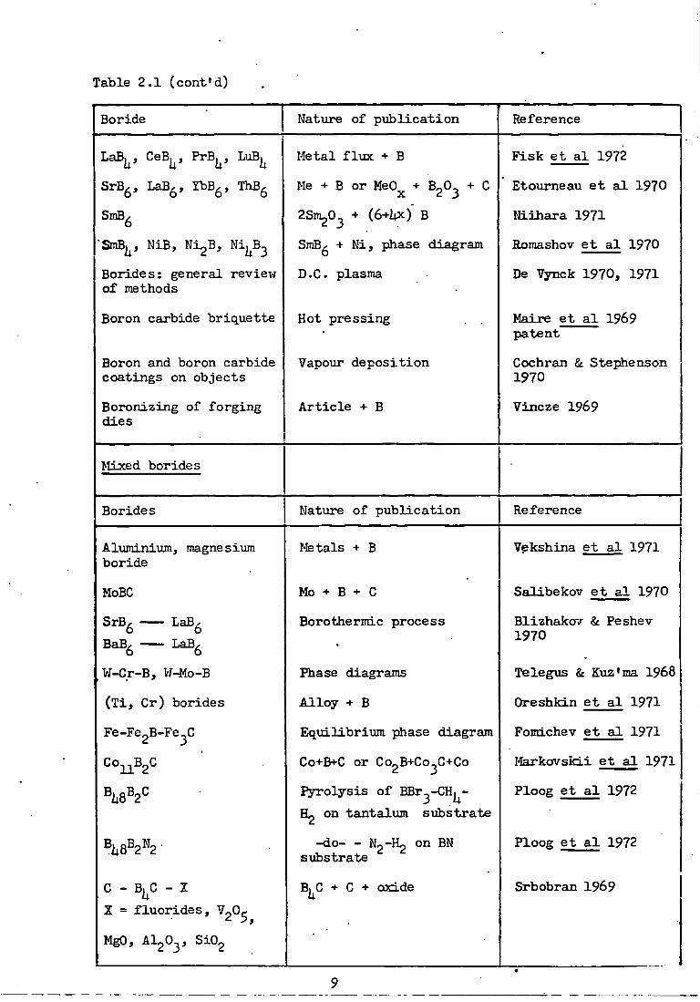
Table 2.1 (cont'd)
Boride Nature of p u b l i c a t i o n Reference
LaB^, CeB^, PrB^, LuB^ Metal f l u x + B F i s k e t a l 1972
SrB^, LaB^^, TbB^, ThB^ Me + B or MeO^ + B^O^ + C Etoumeau e t a l 1970
SmB^ aSm O + (6+ijX) B Niih a r a 1971
'SriB^, NiB, Ni^B, Ni^^B^ Romashov e t a l 1970
Borides: general review of methods
D.C. plasma De Vynck 1970, 1971
Boron carbide briquette Hot pressing , . Maire e t a l 1969 patent
Boron and boron carbide coatings on objects
Vapoiir deposition Cochran £c Stephenson 1970
Boronizing of forging d i e s
A r t i c l e + B Vincze 1969
Mixed borides
Borides Nature of p u b l i c a t i o n Reference
Aluminium, magnesium boride
Metals + B Vekshina e t a l 1971
MoBC Mo + B + C Salibekov e t a l 1970
SrB^ LaB^ BaB^ LaB^
Borothermic process Blizhakov & Peshev 1970
V/-C_r-B, Vf^o-B Phase diagrams Telegxjs & K\iz*ma 1968
( T i , C r ) borides A l l o y + B Oreshkin e t a l 1971
Fe-Fe^B-Fe^C Eqxiilibrium phase diagram Fomichev e t a l 1971
Co^B^C Co+B<-C or Co^B+Co^C+Co Markovskii e t a l 1971
P y r o l y s i s of BBr^-CH|^- Ploog e t a l 1972 H2 on tantalum substrate
-do- - N2-H2 on BN substrate
Ploog e t a l 1972
C - B^C - 2 B^C + C + 03CLde Srbobran 1969 X = f l u o r i d e s , VgO^
MgO, Al^O^, Si02

Table 2.1 (cont«d) Carbides
Carbides Nature of p u b l i c a t i o n Reference
Titanium, zirconiTom carbides
Me + C Davydov et a l 1970
IVA - VHA group metals carbides
I n powder form from solu t i o n i n molten z i n c
Gurin e t a l 1971
General review of methods of production
D.C. plasma De Vynck 1970, 1971
Preparation of boron carbide
By using a radio-frequency plasma
' MacKinnon & Wickens 1973
10

2.3 Thermodynamics of boride and carbide formation
2.3»1 Ellingham diagrams
. The v a r i a t i o n of standard free energy of formation A G ^ and
the production and s t a b i l i t y of the various borides and carbides were
correlated over xri.de ranges of temperature (Shaffer & Samsonov, I96I4.,
JAMF tables 60-72). The temperature v a r i a t i o n o f ^ G ° ^ per g-atom
of boron and carbon i s compared for the formation of borides and
carbides, f i g s . 2.1-2.3. The temperature vsiriation of standard f r e e
energy i s best represented by Ellingham diagrams (I9IU). F i g . 2.1
represents the free energy of formation of the boride, carbide and
oxide of titanium, plots for other metals give s i m i l a r r e s u l t s .
F i g - 2.2 compares the standard free energies of formation of d i f f e r e n t
methods of formation of boron carbide. F i g . 2.3 cou^jares the thermo
dynamic data for various methods of formation of titanium diboride.
Equilibrium compositions of the systems represented on
Elliniiham diagrams are r e a d i l y readable over the d e s i r e d temperature
range by the Richardson & Grants {195U) nomographic s c a l e . High
temperature materials such as borides, carbides and other r e f r a c t o r y
materials have s i g n i f i c a n t l ^ l a r g e vapour pressiires a t moderate temper
ature, l i m i t i n g t h e i r p r a c t i c a l a p p l i c a t i o n s a t higher ten^eratures.
•flie Ellingham diagrams for these compounds are u s u a l l y l i n e a r . Their
slope depends upon whether thermodynamically the r e a c t i o n proceeds i n
the forward or reverse d i r e c t i o n as the temperature i s i n c r e a s e d and cn-
volume changes accompai^ying the r e a c t i o n . Other f a c t o r s as the
temperature-sensitivity of the extensive properties are approximately
interbalanced:
AG°^ = - T A S°
A plot of the fre e energies of formation of boride^ carbide
11

and oxide, f i g . 2.1, of titanium compares i t s r e l a t i v e a f f i n i t i e s
f o r boron, carbon and oxygen and gives iii^jortant information about
the co-existence of these compotinds. The points of i n t e r s e c t i o n of
the cxirves shovx the equilibrium co-existence of each p a i r of compounds.
At a l l other temperatures, the compound with the more negative f r e e
energy v / i l l be the more stable. I h i s vri.ll determine the d i r e c t i o n of
the interconversion of the compounds a t d i f f e r e n t temperatures.
A n a l y s i s of free energy data (Schwarskopf & G l a s e r , 1953) shows
that diborides of the fourth and f i f t h odd (A) metal subgroup have
higher thermodynamic s t a b i l i t y than of other metals. Diborides of
other groups, e.g. MgE2 and CrBg, show a decreasing trend i n s t a b i l i t y
as compared with group IV. Diborides of group IV t r a n s i t i o n metals
and monoborides of group VI t r a n s i t i o n metals (Schwarzkopf & G l a s e r ,
1953) are the most stable of a l l the borides. I n groi^) V d i f f e r e n t
borides of the same t r a n s i t i o n metals have s i m i l a r thermodynamic
s t a b i l i t y . For group IV, V and VI, the M-B bond strength, as deduced
from a comparison of m.p, of borides, i n c r e a s e s with the atomic
weight of the metals i n each period and decreases with atomic weight
w i t h i n each group.
Despite t h e i r usefulness, Ellingham diagrams have some
inadequaciesi v i z .
( i ) The d i s t r i b u t i o n of the r e a c t a n t s and products he tureen
the d i f f e r e n t phases i s not taken i n t o account.
( i i ) Uie formation of i n t e r m e t a l l i c compounds and other mixed
phases between products and reactants i s p o s s i b l e .
( i i i ) The compounds are assumed to be of d e f i n i t e composition,
although i n p r a c t i c e t h i s may not be so f o r ma^y
r e f r a c t o r i e s .
- • • 12

F i g . 2.1 Ellingham diagram f o r T i C , TiB2, TiO^
-56.0
-97.0
U -138.O
-179.0
-220.0 800 1600 2 400
T e m p e r a t u r e K
13
( A f t e r S c h i c k , 1966)
3200 4OO0

( i v ) They in d i c a t e only whether a process is thennodyanically
f e a s i b l e , but not whether i t i s k i n e t i c a l l y favourable.
I n p a r t i c u l a r , s o l i d - s t a t e r e a c t i o n s which are thermo-
dynamically f e a s i b l e are often k i n e t i c a l l y unfavourable;
t h i s might apply to reactions i n v o l v i n g borides and
carbides.
Xv) The free energy changes r e f e r to standard s t a t e s only,
conditions never r e a l i s e d i n dynamic systems;
However, these inadequacies do not diminish the value of the diagrams
i n terms of t h e i r ready evaluation and ease of i n t e r p r e t a t i o n . Sources
f o r r e l i a b l e thermodynamic information are the U-S. Bureau of Standards
dPublication 1952, e t c ) , JANAF Thermochemical t a b l e s and Supplement
(1960-71), Schick (1966) and VJicks & Block (1965). The second most
important thermodynamic function i s the enthalpy change of the
reaction- I t shows the endothermicity or exothermicity of the process-
I t i s applicable to open and closed processes, i . e . those i n v o l v i n g
formation of gaseous products from s o l i d s and condensation of i n i t i a l
gaseous reactants to form s.olids.
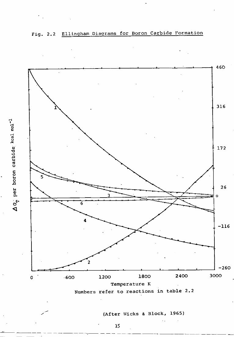
2.3.2 Application to production processes
Free energy changes have been pl o t t e d against temperature f o r
s i x methods of production of boron carbide as shovm i n f i g . 2.2. A
b r i e f d i s c u s s i o n of t h i s information f o r each r e a c t i o n i s given below:
( i ) 2B2O-J+ 7C = B^C+6C0(g) Thermodynamically f e a s i b l e at temperatures ^ 2320K. The
operating free energy
/ ^ G ^ = AG°^+RTlnp(CO)
shows t h a t an 'open' system would be favourable. However,
i f the v o l a t i l e nature of B ^ O ^ i s taken i n t o consideration,
the equation becomes:
F i g . 2.2 E l l i n g h a i n Diagrams f o r Boron C a r b i d e Formation
460
10 u
Q • H -Q u ca o c o u o 1 <u a
o
-116
-260 3000 600 1200 1800 2400
Temperature K Numbers r e f e r to r e a c t i o n s i n t a b l e 2.2
( A f t e r Wicks & B l o c k , 1965)
15

TABLE 2.2
BORON CARBIDE
F e a s i b i l i t y Heat of Reaction Range Reaction Eq. Constant
K k ca]. mol 0...lOOOK 0...li0C0K
1. 2B20^+7C = Bji C + 6Co >2300 ©...ixio"^
2. 2B20y-6Mg+C -= Bj C+6MgO O...2ii00 -252...-7I45 10-^^...0
3. l^BCl^+liHg+CH^ = B^C+12HC1 >1700 123. . .80 0...1X10^
l l . liBCl^+SHg+CClj^ - BJ^C+16HC1 ' >300 5I4...-56
5. 1;BC1^+6H2+C = B^C+12HC1 >3300 106...50 O . . .3
6. liB+C = B^C 0...3100 -10...-75 i o 2 ^ . . o

F i g . 2.3 E l l i n g h a m Diagrams f o r T i t a n i u m D i b o r i d e
170
c o u o 0) o B u d) a m 0)
•H
o rH (0 o o
800 1600 2400 3200 4O0O
Temperature K
Numbers r e f e r to r e a c t i o n s i n t a b l e 2.3
( A f t e r S c h i c k , 1966) 17

TABLE 2.3 TITANIUM DIBORlDE
Reaction F e a s i b i l i t y Range
Heat of Reaction Eqm. Constant
K k c a l mol 0...ii000K O.a.liOOOK .
1. T i + 2B = TiBg 0... -66. . . -I1O3 10^^... 10^
2. TiOg + 2B + 2C = TiB^ + 2C0 >1300 10li...62 O-.-liXlO"*--^
3. TiCl^^ + 2BC1^ + •= TiB2 + lOHCl > 1200 99...hi 0...3X10®
1|. TiOg + B20^ + 5C = TiB2 + 5C0
5. 2Ti02 + B^C + 3C = 2TiB2 + hCO
> 1 5 0 0
>1200
327...1420
217...383
o...io-^^
0...10''-'
6. 3Ti + *B C 2TiB2 + TiC 0 . -155...HA io39...io^7
7. 2Ti + B^C = 2TiB2 + C 0---- -120...52 10^9.. . 10^6
8. 3Ti02 + 362©^ + lOAl = 3TiB2 + 5Al20^ 0...3200 - 5 6 . . . . 6 5 9 10^^...0
9. Ti02 + B^O^ + 5Mg = TiB2 + 5Mg0 0... -2ii3...232 10^^...lo'
00

A G ^ = AG°^-RTlnp(B20^)+RTlnp(C0)
Hence, an 'open' system may not be favoiarable, p a r t i c u l a r l y
at higher temperatures,
( i i ) 2B20^+6Mg+C = B C+6MgO
The reaction i s thermodynamically f e a s i b l e over the
temperature range 0-2500^C (Glasson & Jones, 1969). The
optimum operating temperature must be determined by the
k i n e t i c s involved. The r e a c t i o n i s exothermic ( i . e . ^ H^
i s negative) and the operating free energy change i s given
by
AG^ = AG°^-RTlnp(B20^)-RTlnp(Mg)
This suggests that a 'closed' system i s p r e f e r a b l e ; t h i s
i s l i k e l y to favour the k i n e t i c s of the process.
( i i i ) iiBCl^+UH2+CH|^ = B^C+12HC1
This reaction i s thermodynamically f e a s i b l e above 1700K.
The optimum operating temperatiu^e must be determined
from the k i n e t i c s involved.
( i v ) iiBCl^+8H2+CGl^ = B^C+16HC1
The reaction i s thermodynamically f e a s i b l e a t a l l temper
atures greater than 300K.
(v) iiBCl3+6H2+C = B^C+12HC1
The r e a c t i o n i s thermodynamically f e a s i b l e a t temper
atures greater than 3100K.
( v i ) liB+C = B^C
The r e a c t i o n of e l e m e n t a l ^ - rhombohedral boron v/ith
graphite i s thermodynamically f e a s i b l e over the
ten^jerature range 0-3100K.
19

. Thermodynamic functions f o r the metal borides of group IVA-VA
have been computed over the temperature range 0-UOOOK. Free energy
change values have been plotted to compare the various methods of
formation f o r TiB2. A table of f r e e energy change, heat of r e a c t i o n
and equilibriiim constants a t d i f f e r e n t temperatures f o r one of these
reactions i s given i n Appendix I I . Complete ta b l e s are a v a i l a b l e f o r
a l l methods of boride production f o r the metals titanium, zirconium,
hafnium, niobiimi, tantalum and magnesium.
Fourth and f i f t h odd (A) subgroups metal carbides are of the
highest s t a b i l i t y , e.g. SiC and TiC . This s y s t e m a t i c a l l y drops f o r
carbides of lower groups, e.g. CUC2 and AlC^, and t r a n s i t i o n metal
carbides i n groups VI to V I I I , e.g. WC.
A comparison of the r e l a t i v e r e a c t i v i t y of metals towards boron
and carbon shows that borides are comparatively more st a b l e than
carbides and e a s i l y formed. This behaviour i s a t t r i b u t e d to the
comparatively open s t r u c t i i r e of elemental boron compared ivith t h a t
of carbon. Boron r e t a i n s i t s elemental groupings, while carbon l a t t i c e s
are disrupted during r e a c t i o n . This makes ready ingress of the metal
component possible to form the binary boride, e.g. AlB-^^^ (but not A 1 B ^ 2 )
( W i l l , 1966); a l s o ScB^2 ^ 1 2 ^ ^ ^ ^ have B-j^-cubo-octahedra
(Matkovich e t a l , 1965)- The s o l u b i l i t y of boron i n t r a n s i t i o n metals
i s r e l a t i v e l y loi-7 except T^en i t s i i b s t i t u t e s an atomic s i t e i n the
metal, thus causing shrinkage of the u n i t c e l l (Hansen & Anderko, 1958;
Pearson, 1958; Aronsson, 1960) (e.g. with Mo- and W-B a l l o y s ) . Ajay
increase i n the c e l l dimensions of the t r a n s i t i o n metals i s an
i n d i c a t i o n of the i n t e r s t i t i a l d i s s o l u t i o n of boron except when such
increases are due to the uptake of nitrogen or oxygen. These elements
though more electronegative are small enough to be d i s s o l v e d i n t e r -
20

E t i t i a l l y . Homogeneity ranges of primary s o l i d solutions are consider
ably a f f e c t e d by the free energy of intermediate phases. The i n t e r
s t i t i a l s o l u b i l i t y of non-metals i n s o l i d metals i s c o n t r o l l e d by
el e c t r o n i c f a c t o r s a l s o . This i s discussed i n the next s e c t i o n .
2,U The structure of boron carbide i n r e l a t i o n to i t s r e a c t i o n i-rLth medals
The c r y s t a l l o - c h e m i c a l structure of boron carbide and i t s
r e a c t i o n with titanivmi and chromiiim has been comprehensively reviewed
\jy Jones (1970). A b r i e f d i s c u s s i o n of the structure of boron carbide
and i t s r e l a t i o n to i t s properties and r e a c t i o n with i r o n and other
metals i s presented below.
The structure of boron carbide with composition of ^-^2^}
i d e a l l y represented by regular icosahedra where 12 boron atoms are
situated at the v e r t i c e s and has i n t e r s t i t i a l spaces to accommodate
up to 3 carbon atoms. The two end carbons i n the -G-C-C- chain d i f f e r
from the c e n t r a l carbon which may be replaced by boron atom gi v i n g the
compound of composition B ^ Cg* A homogeneous continuous mixture of
these two compositions i s considered to co n s t i t u t e the boron carbide
compound. According to Fourier s y n t h e s i s of e l e c t r o n d e n s i t i e s of 2+ 2-
boron csirbide two formulations-are suggested; ( i ) B-^^ or ( i i )
(CBC)*(B22C)~- O r d i n a r i l y a well-annealed boron carbide of B^C
composition i s s t r u c t u r a l l y formulated as (CBC)'*^(B^C)" t o i n d i c a t e
probable charge t r a n s f e r and i s considered to be e n e r g e t i c a l l y
preferred- The rhombohedral lattiot:constants of boron carbide are
a^= 5-167i0.003S and o<= 65.68T0.05 and a^ = 5.582 and c"^ = 12.0o2 for i t s hexagonal c e l l containing three rhombohedral u n i t s t r u c t u r e s .
Properties of boron carbide such as very high ^-rear-resistance,
abrasion-resistance, heat r e s i s t a n c e and microhardness are explained
21

i n terms of i t s electronic c o n f i g u r a t i o n (Oreshkin e t _ a l , 1970).
Modern theory a t t r i b u t e s i t s high abrasiveness t o the f a c t t h a t boron
and carbon^in i t s composition a t t a i n the e l e c t r o n i c c o n f i g u r a t i o n 2
having highest s t a b i l i t y . Boron atoms having s p co n f i g u r a t i o n i n 2
the ground state undergo s ^p t r a n s i t i o n t o acquire sp configur
a t i o n . This tends t o s t a b i l i z e f u r t h e r t o sp^ c o n f i g u r a t i o n due t o 2 2
a t t r a c t i o n of the electrons of carbon atoms w i t h s p c o n f i g u r a t i o n
of valency electrons. Carbon undergoes s->p t r a n s i t i o n to acquire more
stable configuration. Thus i n the l a t t i c e of the boron carbide the
boron atoms w i l l have the s t a b i l i t y of sp^ co n f i g u r a t i o n by exchange
of electrons betx-;een boron atoms and due t o breakdoi-jn of the sp^ config
uration of carbon atoms. As a r e s u l t of shortage of electrons f o r t r a n s i t i o n t o sp- configuration a p a r t of the boron atoms remains w i t h
2 less stable sp configuration. Thus compared w i t h diamond and the
analogous cubic boron n i t r i d e (»bora2on») which have a l l the atoms w i t h
sp^ configuration and hence highest s t a b i l i t y ( w i t h respect to energy),
boron carbide has higher i-iear resistance index- Because of t h i s unique 2 3
electronic structure ( p a r t i a l conversion of sp t o sp c o n f i g u r a t i o n of.
boron) a l l the remaining compounds are i n f e r i o r t o boron carbide i n
resistance t o wear and other properties. ;
Improvement i n the properties of boron carbide sintered w i t h
d i f f e r e n t metal powders (Chapter h) w i l l depend upon the s t a b i l i t y of
elec t r o n i c configuration of the f i n a l product. I n i t s r e a c t i o n w i t h
i r o n , p a r t i a l t r a n s f e r of electrons takes place towards boron carbide, 2 3
which increases i t s s t a b i l i t y by t r a n s i t i o n of sp t o sp configuration.
At the same time the strength i n the t r a n s i t i o n i s increased due t o an
increase i n the s t a b i l i t y of i r o n due t o t r a n s i t i o n of d^-^ d^ cohf i g -
22
u r a t i o n . Thns i r o n has been found t o be most e f f e c t i v e s i n t e r i n g
additive i n the present v;ork (Table U.IO). The effectiveness of
other metals v j i l l vary according t o the ease of e l e c t r o n t r a n s f e r
and the s t a b i l i t y of the metal atom as a r e s u l t of t h i s interchange
of electrons. Metals used i n t h i s work possess p a r t i a l l y f i l l e d d i o r b i t -
als i n t h e i r penxoltimate s h e l l and shox-j v a r i a b i l i t y of oxidation states.
I t can be assumed that a dominating r o l e w i l l be played e i t h e r by sp-
hybr i d states of boron carbide, or the d-state of the metal i n the
i n t e r a c t i o n of valence electrons. The precise nature of t h i s phenom
enon i s s t i l l not too c l e a r l y imderstood. However, i t would be l o g i c a l
t o sviggest t h a t t r a n s f e r of electrons i s dir e c t e d towards boron carbide
i f they acquire r e l a t i v e l y stable c o n f i g u r a t i o n as a r e s i i l t of t h i s
exchange.
2.5 Bonding and c r y s t a l structure of borides and carbides
A comprehensive review discussing the r e l a t i o n s h i p between the
bonding and c r y s t a l structure of bojrides and carbides i s given by
Glasson & Jones (1969a). A summary of t h i s i s given below.
I t was pointed out ,(Hagg, 1931) t h a t t r a n s i t i o n metal binary
r e f r a c t o r y borides and carbides have simple "normal* structxires i f
the radius r a t i o r : r of the non-metal and metal atoms i s less than X m
0.59 (corresponding t o a metal t o non-metal radius r a t i o of over 1.70).
Greater non-metal r a d i i cause the \ i n i t c e l l dimensions of the i n t e r
s t i t i a l phases t o extend and reduce the radius r a t i o f o r normal, s t r x i c t -
ures. Despite the f a c t t h a t decreased metal atom size leads t o complex
structures, most of these compounds are metal l i e i n nature. Later t h i s
l i m i t i n g radius r a t i o rule was found t o be applicable only t o carbides
(Schwarzkopf & K i e f f e r , 1953). • This behaviour of borides has been a t t r i b u t e d ( K i e s s l i n g , 1950)
23

t o the tendency of boron atoms t o form chains, sheets or three-
dimensional networks. Hagg's rule appears t o be confined t o phases
not containing d i r e c t l y interconnected non-metal s t r u c t u r e elements.
Accordingly, eight d i f f e r e n t types o f boride c r y s t a l s t r u c t u r e s have
been described by Schwarzkhopf and K i e f f e r (1953) f o r boride phases
i n the composition range M^B t o MB-j 2" ' ^ v a r i a t i o n s have been
reviewed l a t e r ( K i e f f e r and Benesovsky, 1963; Post, 196i4; Aronsson,
Lundstrom and Rundqvist, 1965) w i t h composition ranges M B t o MB^2*
extending t o MB^Q.
Most of the r e f r a c t o r i e s (Hagg, 1931) discovered e a r l i e r were
mouocarbides vrith radius r a t i o s i n the range O.Ul-0.59. These were
characterised by ro c k - s a l t structures i r r e s p e c t i v e of the parent metal
structure. Rundle (19U8) assumed the presence of octahedral metal to
non-metal bonding, and developed Pauling's o r i g i n a l concept of
resonance of the bonds of h- covalent C amongst the 6 p o s i t i o n s (Paxiling
19U0, 19ii7, I9U9)- Most of the properties such as hardness, high m.p.
and e l e c t r i c a l conductivity have been explained i n terms of resonating
bond structiires and i o n i c structures i n v o l v i n g homopolar and hetero-
polar forces. A d i f f e r e n t theory, introduced by Ubbelohde (1931, 1937)
and Omanskiy (19U3) (see also Samsonov & Umanskiy, 195?) have been
developed by Samsonov and Meshpor (1958, 1959) and reviewed r e c e n t l y
f o r n i t r i d e s (Glasson and Jayaweera, 1968). According t o t h i s theory,
the non-metal contributes bonding valence electrons t o the t o t a l
system of electrons, a t le a s t p a r t i a l l y f i l l i n g the e l e c t r o n defect of
the metal atoms. Interatomic bonding i s f u r t h e r strengthened by the
donor-acceptor i n t e r a c t i o n forces. Therefore, heats of formation of 1/ '
borides and carbides increase w i t i i 'acceptor a b i l i t y ' Nn of the
2U

atoms of the me t a l l i c components, T-^ere N i s the p r i n c i p a l l^uantum
number of the p a r t i a l l y f i l l e d d- (or f - ) s h e l l and n i s the number of
electrons i n t h i s s h e l l (Samsonov, 1956). A s i m i l a r v a r i a t i o n i n the
l a t t i c e energy and the hardness v/ith acceptor a b i l i t y of m e t a l l i c
ccmpounds takes place. Also, the work f u n c t i o n of the electrons i n the
case of thermionic emission r i s e s and e l e c t r i c a l r e s i s t i v i t y drops vdth
an increase i n (Samsonov and Neshpor, 1959)- The e l e c t r o n density
o f the bonds also varies v j i t h the i o n i s a t i o n energies of the non-
metal atoms; t h e i r capacity t o donate electrons r i s e s i n the d i r e c t i o n
0,N,C,B,Si- This view i s repudiated by Rundle (19U8), but Schwarzkopf
and K i e f f e r (1953) hold t h a t vrlth l i g h t e r atoms i n r e f r a c t o r y m a t e r i a l s ,
assuming m e t a l l i c s t a t e , f a i r l y strong metal t o non-metal bonds can be
formed. The Ubbelohde-Samsonov theory leads t o comprehensive and
qua n t i t a t i v e explanation of physical and chemical behaviour. I t s scope
i n r a t i o n a l i s i n g the up-to-date information f o r borides and carbides i s
i l l u s t r a t e d nox-j; types of experimental i n f o r m a t i o n leading t o i t s
a p p l i c a b i l i t y are indicated.
2.6 Properties of borides and Carbides
Properties of borides and carbides have been discussed by Shaffer
& Samsonov (I96h), Campbell e t a l (19U9), Samsonov 5c Golubeva (1956),
Munster (1959), McDonald & Ansley (1959), Webb e t a l (1956), Aronsson
(1960), Stewart & Cutler (1967), Thompson & Wood (1963), Thompson (1965,
1970a, 1970b, 1970c), Storms (1967, 1972), Toth (1971), Kosolapova (1971),
and Glasson fit Jones (1969a). Table 2.U siimmarises more recent i n v e s t
i g a t i o n s on the various aspects of the properties of borides.
2.7 Sin t e r i n g of borides and carbides
The duration of s i n t e r i n g i n the formation of borides and carbides
and t h e i r subsequent c a l c i n a t i o n a f f e c t s t o a large extent t h e i r
25

Table 2.h
Boride Property Reference
General, r e a c t i o n t-jith HCl and HNO^
Markovskii e t a^ 1969
Scandium and y t t r i u m borides
KMR spectrum Barnes e t a l , 1970
ZrB2 Thermal c o n d u c t i v i t y Neshpor e t a l , 1970a
TiB2, ZrB^, HfB2 Thermal d i f f u s i v i t i e s Branscombe & Hunter, 1971
Nb^B2, NbB, Nb B| , NbB2
Physical properties Kovenskaya & Serebryakova, 1970
IVA-VA metal borides Thermal expansion Samsonov e t a t , 1971a
TiB2, ZrB2, HfB2, Thermal expansion Keihn & Keplin, 1967 NbB2, TaB2
Tr a n s i t i o n n e t a l borides
Heat capacity Kuentzler, 1970a, 1971
CrB2 Calorimetric and r e s i s t i v e magnetic properties
Castaing, 1972
HfB2 Chemical s t a b i l i t y x-rlth HCl, H2S0^, HCIO^, HNO^, KH^Cl + HCl, CH COOH, H2O2, m y A i r
SavitskU e t a l , 1970a
TiB2, ZrB2, VB2, HfBg, NbB2, TaB2
Chemical s t a b i l i t y tovjards HCl, HCl + H2O2, HCl + H2C20^, ^2^\ - H2O2, H2S0^ + H2C20^, HNO , H2O2, H2O, H2C20^
Kugai & Nazarchuck 1971a
Zr02 - ZrB2 HfO2 - HfB2
Reactions a t 1000 -2000* C
Marek e t a l , 1971
NbgO^ - NbBg T^SL^O^ - TaB2 Cr20^ - CrB2
26

TABIE 2.ii (cont'd)
Boride Property Reference |
Borides of t r a n s i t i o n metals TiB^, ^rB^, CrB2, MoB^
Reaction w i t h BaCO^ or Ca
Kugai & Nazarchuck, 1971b
Molybdenum and tungsten borides
S t a b i l i t y , acid Kugai, 1971
SrB^ - LaB^, BaB^ - LaB^
Thermionic properties •Bliznakov & Peshev, 1970
Niobium, tantalum, molybdenum and tungsten borides
Resistance against carbonizing
Samsonov e t a l , 1970a
TiB^, ZrBg, HfB^, VB^, NbB2, TaBg, CrB^, MoB,
Heat treatment w i t h carbon
Levensfcii e t a l , 1968
M02B^, Vre, VJ^Bj
TiB2, VJ^Bj, ( T i , Cr) Vfear resistance Oreshkin et a l , 1971 boride
Cobalt and n i c k e l borides
S t a b i l i t y t o carbon Markcvskii e t a l , 1971
I n t e r a c t i o n xri.th molybdenum, tantalum and graphite
Gert e t a l , 1969
LaB^, CeB^, PrB^ KdB^
Resistance t o H2O, a l k a l i e s and acids
Kosolapova & Domasevich, 1970
TB^, LaB^, ThB^
Magnetic susceptibi l i t y thermoelectric power, s p e c i f i c heat
Etoumeau e t a l , 1970
LaB^, NdB^, SmB , DyB^
Oxidation i n a i r Timofeeva & Timofeeva, 1971
SraB^ Reaction w i t h n i c k e l Romashov e t a l , 1970
Borides i n general Systematic phase chemi c a l analysis
Vekshina & I4arkovskii, 1969 .
FeB, Fe2B E f f e c t of temperature on physical properties
K u n i t s k i i & Marek, 1971
27

TABLE 2.U (cont'd)
Boride Property Reference
FeB, Fe^B R e s i s t i v i t y , thermo-enf, thermal conducti v i t y and expansion 70 - 1300K
K o s t e t s k i i e t a l , 1971
FeB, Fe^B Anisotropy o f thermal expansion
Lyakhovich e t a l , 1971
(Fe-Co) boride, (Co-Ni) boride
Heat capacity Kuentzler, 1970b
Bh^B^, RhB^ -j^ Hardness Kosenko et a l , 1971
Borides i n general Fusion and heat compression
Pastor, 1969
Boron-coated metal objects
Mechanical properties Ducrot & Poulain, 1970
AlB^O Crystal s t r u c t u r e and electron d i s t r i b u t i o n
W i l l , 1970
ZrBj - Mo St r u c t u r a l properties K i s l y i & Kuzenkova, 1966
Nb^B2, NbB, Nb-B , 'NbB2, Cr^B, Cr^B2, CrB, Cr^B^, CrB2
E l e c t r i c a l resistance,, thermo e l e c t r i c pote n t i a l , ^ 1 / , H a l l c o - e f f i c i e n x
Sarasonov e t a l , 1971b
IrB^^35, I r B ^ ^ ^ ,
^^^0.9 Crystal s tructure Rogl e t a l , 1971
SmB Electronic configTir-a t i o n , magnetic and e l ec t r i c properties
R-me, 1970 Cohen e t a l , 1970
General borides Role of valence electrons
Sleptsov & Kosolapova, 1970
28

Tables 2,U (cont'd)
Carbides and mixed borides
Carbide Property Reference
ZrC Hot hardness S a v i t s k i i et a l , 1970b
Tran s i t i o n metal carbides
Abrasive wear Artamonov & Bovkun, 1970
MeC and Me(C,N) of group IVA & VA
Systematic chemical and electrochemical separa t i o n
Georgieva et a l , 1969
Carbides i n general Systematic phase chemi c a l analysis
Vekshina & Markovskii, 1969
I n t e r a c t i o n w i t h C • X ( f l u o r i d e s , ^2^$' £0, Al^O^, 5102)
Srborbran, 1969
P j T T o l y t i c B|C E l e c t r i c a l resistance, e.ra.f., thermal cond u c t i v i t y and micro-hardness
Neshpor e t a l , 1970b
B C Optica l properties Werheit e t a l , 1971
Cr^C2 - 2^0, B C - SiC, Cr^C^ -SiC
I n t e r a c t i o n i n welding
Oreshkin et a l , 1970
Dib o r i d e - n i t r i d e system
Dry f r i c t i o n and wear Medvedev fic Sin,kov, 1971
Crystal structure and electron d i s t r i b u t i o n
W i l l , 1970
/ - VC,/-NbC, J - TaC
Crystal structure Yvon &: Parthe, 1970
Carbides i n general Properties of carbides based on electronic c o n f i g u r a t i o n
Samsonov, 1970
29

chemical reactivity. Extensive studies on the sintering of oxides
and to a lesser extent of nitrides have been made (Glasson &
Jayai-reera, 1968). Theories of sintering have been established by
Huttig (19iil), Kingery (1960), Coble (1961, 1961*), Kuczynski (1961),
VJhite (1965) and Fedorchenko & Skorokhod (1967). The rate of
sintering i s considerably increased by pressing the powdered materials
before calcining i n vacuo to stop hydrolysis and oxidation (Chiotti,
1952; Geguzin & Partskaya, 1967)*
Materials (Schwarzkopf £c Kieffer, 1953) can be con^jacted and
pressed to almost theoretical densities by hot pressing them, e.g.
oxides such as MgO, CaO, ^^^^ (Carruthers & VJheat, 1965; VJheat &
Carruthers, 1961). Small amounts of impurities, especially those
giving r i s e to gaseous products such as hydroxides and carbonates
hinder the sintering. In the presence of nitrogen, carbides are
•converted to carbide-nitride solid solutions, e.g. TiC (Zelikman &
Loseva, 19ii75 Zelikman & Gorovits, 1950) and ZrC (Duwez. fie Odell, 1950).
Hot pressing i s often carried out i n vacuum to avoid such contaminations
(Glasson, 1967). Small quantities of low-melting additives generally
Increase the rate of sintering (Glasson, 1967) usually at the cost of
excellent optical and mechanical properties. Cermets (Schwarzkopf fic
Kieffer, 1960) or surface coatings having superior properties may be
obtained by sintering very b r i t t l e borides and carbides with metals
such as cobalt (Powell et a l , 1966).
2.7.1 General principles of the mechanism of sintering
ariH hot pressing
The process of sintering i s that by viiich povjders are consolid
ated into strong, and usually dense poly c r y s t a l l i n e aggregates by
30
heating. Systems undergoing s i n t e r i n g are of two types, namely:
( i ) Homogeneous systems consisting of a single component
or components vihich give continuous series of s o l i d
solutions.
( i i ) Heterogeneous systems consisting of mxiltiple component
systems.
.In the homogeneous s i n t e r i n g of a powder, d i s t i n c t i o n can be
made beti-reen two overlapping stages o f s i n t e r i n g . The f i r s t stage i s
characterized by the formation and grox-rth of bonds, i . e . the contact
areas beti-Jeen adjacent powder p a r t i c l e s . The growth of these contact
areas takes place during the e a r l y stages of s i n t e r i n g , when the
material i s densified and the pore volume decreased. Under favourable
conditions the pores are p r a c t i c a l l y eliminated. The surface free
energy i s considered t o be the d r i v i n g force i n both stages of
s i n t e r i n g . The energy required f o r s i n t e r i n g i s supplied by the
decrease of sxirface areas or by the replacement of high-energy i n t e r
facings by those of lox-rer energy, e.g. g r a i n bo\indaries. The siirface
free energy i s s o i f f i c i e n t t o account f o r s i n t e r i n g , provided a suitable,
mechanism i s available f o r the transport of atoms involved i n the
consolidation of powder compacts. The follovTing f i v e mechanisms are
possible i n the case of homogeneous mate r i a l s :
( i ) Evaporation folloT-jed by condensation.
( i i ) Siirface d i f f u s i o n .
( i i i ) Volume d i f f u s i o n .
( i v ) Viscous flovj (Wex-rtonian flow characterized by a l i n e a r
r e l a t i o n s h i p betv/een s t r a i n rate and s t r e s s ) .
(v) P l a s t i c flovj (Bingham flow characterized by the existence
o f a y i e l d s t r e s s ) .
31

D i f f e r e n t theories o f s i n t e r i n g and mechanisms of m a t e r i a l and
pore transport have a t t r a c t e d much a t t e n t i o n o f v;orkers .in the f i e l d
of s i n t e r i n g , Alexander et a l (19U5), Herring (1950), Kingery e t a l
(1955), Murray et a l (l95ii), Nabarro (19U8). The s i n t e r i n g o f B C and
other r e f r a c t o r y materials has been revievied comprehensively by Jones
(1970)". Points a r i s i n g from t h i s review and recent advances i n the
technology of si n t e r i n g are presented here, •
2.7.2 Role of volume, Grain boundary and Surface d i f f u s i o n
The r o l e of volume, grain boundary and surface d i f f u s i o n during
the i n i t i a l , intermediate and f i n a l stages of s i n t e r i n g has been
studied by R i s t i c (1969). Separate eqiiations f o r a l l three mechanisms
have been formulated. His model f o r the i n i t i a l stages of s i n t e r i n g ,
based on the shrinkage of a wire on a plane, shows considerable
discrepancy from the solutions proposed by e a r l i e r authors. Accord
i n g l y , a s o l u t i o n f o r an i n f i n i t e l i n e has been suggested. Comparison
of r e s u l t s regarded i n the context of some other i n d i c a t o r s shows t h a t
surface d i f f u s i o n i s responsible f o r the mechanism of the process i n
both cases. The intermediate and f i n a l stages of s i n t e r i n g are o f t e n
d i r e c t l y responsible f o r the physical properties o f a s i n t e r e d body.
Hie equations f o r models whose systems are composed o f u n i t s c o nsisting
of e i t h e r cubes, hexagonal prisms, dodecahedrons, or tetrakaidecahedron
are given as:-
(a) Bulk d i f f u s i o n model
l^kT• • . •
(b) Boundary d i f f u s i o n model 2/,
32
n

V7here
P = the volume f r a c t i o n of the pore
D = biOk d i f f u s i o n c o e f f i c i e n t
^ = surface energy
a^ = vacancy volume
t = time
t ^ = time at which the pore vanishes
= boundary d i f f u s i o n c o e f f i c i e n t
J. = edge of the polyhedron
W = boundary vrldth
K^,K2 = constants
k = Boltzmann constant
T = thermodynamic temperature
A comparison of and vrLth Coble's model c l e a r l y shows the
influence of the geometry on d e n s i f i c a t i o n diiring intermediate and
f i n a l stages of s i n t e r i n g . Accordingly i t i s possible t o determine
the c r i t i c a l size of the specimen by means of the equation:
= vacancy d i f f u s i o n c o e f f i c i e n t
t = time
The r o l e of non-stoichiometry i n the s i n t e r i n g of i o n i c s o l i d s
has been studied by Reijnen (1969). This work deals only w i t h the
volxime d i f f u s i o n of vacancies and i n t e r s t i t i a l s , s p e c i f i c a l l y w i t h
the f l u x of vacancies emitted by s p h e r i c a l pores.
Johnson (1969a, 1969b, 1969c, 1970, 1971) has studied extensively
the new methods of obtaining volume, grain-boundary and surface
d i f f u s i o n c o e f f i c i e n t s from s i n t e r i n g data, s i n t e r i n g k i n e t i c s f o r
33

combined volume, grain boundary and surface d i f f u s i o n s , the i n t e r
mediate stage of s i n t e r i n g and the methods of determining s i n t e r i n g
mechanisms. His model f o r the determination of s i n t e r i n g i s given
i n F i g . 2.5.
a
Fig. 2.5 Geometry and atom f l u x paths f o r i n i t i a l
stage model. A, B and C are volume d i f f u s i o n , D i s
gra i n boundary d i f f u s i o n , E i s surface d i f f u s i o n , and
F i s vapor transport.
( A f t e r Johnson, 1971)
I t i s based on the assumption th a t a l l d e n s i f i c a t i o n i s produced by
d i f f u s i o n of atoms from the grain boundary between the p a r t i c l e s t o
the neck surface, by volume or grain boundary d i f f u s i o n or by both
processes acting simultaneously. I t i s assumed t h a t vacancies are
at e q u i l i b r i u m concentration everyvjhere and t h a t the surface and
gr a i n boimdary tensions are i s o t r o p i c . The s i n t e r i n g equation i s
given by:-
X + R cosoL kTa-^^b IV
kTa
where
Z = f r a c t i o n a l neck radius
R = normalized minimum radius of -curvature of neck surface
^ = as defined i n Fig. 2.5
y = f r a c t i o n a l shrinkage A l / L
3li
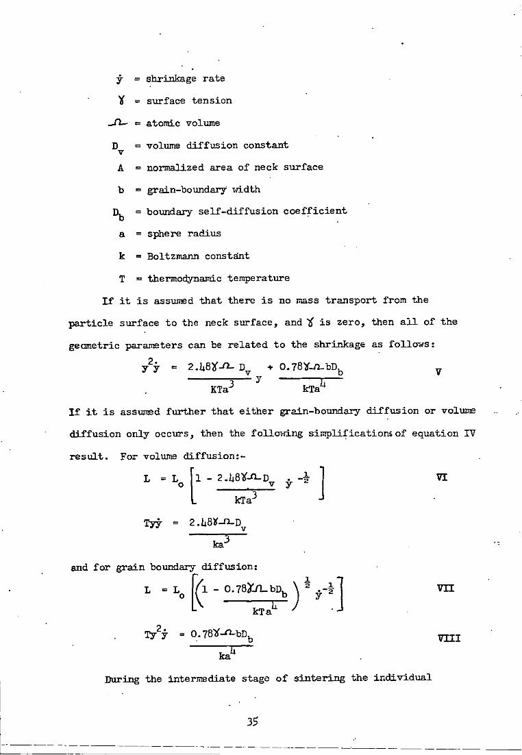
y = shrinkage rate
y = surface tension
= atomic volume
D = voliime d i f f u s i o n constant V
A = normalized area of neck surface
b = grain-boundary vri.dth = boundary s e l f - d i f f u s i o n c o e f f i c i e n t
a = sphere radius
k = Boltzmann constsint
T = thermodynamic temperature
I f i t i s assumed t h a t there i s no mass transport from the
p a r t i c l e surface t o the neck surface, and i f i s zero, then a l l of the
geometric parameters can be re l a t e d t o the shrinkage as f o l l o w s :
'b V 2.
y y 2,ii8}('-^D + 0.78y-n-bD,
KTa^ kTa"*
I f i t i s assTimed f u r t h e r t h a t e i t h e r grain-boundary d i f f u s i o n or volume
d i f f u s i o n only occurs, then the f o l l o v i i n g s i m p l i f i c a t i o n s of equation IV
r e s u l t . For volume d i f f u s i o n : -
1 - S.USV-n-D V y kTa-
VI
Tyy = 2.U8y-n.D
ka-
and f o r grain boundary d i f f u s i o n :
- 0.78yjl-bD,
kTa
0.78y-^bD,
ka^
v n
v n i
During the intermediate stage o f s i n t e r i n g the i n d i v i d u a l
35

p a r t i c l e s at the beginning have more or less l o s t t h e i r i d e n t i t y . The
pores are interconnected by channels l y i n g along , three g r a i n i n t e r
sections. The d e n s i f i c a t i o n mechanisms are the same as those t h a t occur
during the i n i t i a l stage but the geometry i s more complex. Because of
geometric complexities o f the compact, a method o f averaging the
s i g n i f i c a n t geometric parameters i s employed. The r e s u l t i n g equation i s
G dV = 32^-^0^ ^ S + 32^-^ D ^ HL V^^ kT L kT
V V T^ere
G = mean grain diameter
H = average mean surface curvature
= length per u n i t volume of i n t e r s e c t i o n between
gra i n boxindaries and pores
S^ = pore siirface area per u n i t volume
V = instantaneous volume of compact
Equation IX i s an attempt to analyse s i n t e r i n g data when a l l
changes i n the mechanism of mass and pores transport and geometric
fa c t o r s occur. I t has been modified f u r t h e r f o r various states of
s i n t e r i n g and f o r isothermal and non-isothermal s i n t e r i n g .
2.7.3 Role of dislocations
Investigations of s i n t e r i n g processes have included occasionally
e f f o r t s t o observe d i s l o c a t i o n motion during s i n t e r i n g . These e f f o r t s
have been unsuccessfiLl. Hoirever, t h i s does not mean t h a t d i s l o c a t i o n
motion does not contribute to the s i n t e r i n g process* Due t o the nature
of d i s l o c a t i o n s l i p , i t i s probable t h a t a c t u a l observations of moving
dislocations during s i n t e r i n g may be extremely d i f f i c u l t or impossible.
The reason i s t h a t d i s l o c a t i o n generation and motion during s i n t e r i n g
36

w i l l occur most r e a d i l y i n veiy small p a r t i c l e s or c r y s t a l l i t e s . I n
small c i y s t a l s , d i s l o c a t i o n generation v / i l l be a t the g r a i n boundary,
leaving l i t t l e opportunity f o r d i s l o c a t i o n s t o be seen by transmission
microscopy. The d i s l o c a t i o n motion occurs i n large p a r t i c l e s , where
the stress t o cause s i n t e r i n g i s less only a t very high temperatures,
which are probably not a v i l a b l e under the conditions when the microscope
i s i n use. Dislocations can remain i n the c r y s t a l s under c e r t a i n
conditions i n v o l v i n g short heating periods. The r o l e of d i s l o c a t i o n s
i n the d e n s i f i c a t i o n of CoO and NiO v j i t h a dispersion of HgO or CaO
has been studied by Tikkanen and Ylasaari (1969). The disl o c a t i o n s
i n hi^-temperature s i n t e r i n g have been observed by Morgan (1971)-
A comprehensive revievj based on t h e o r e t i c a l and experimental i n v e s t
igations on bubble r a f t s i n t e r i n g , d i s l o c a t i o n nucleation i n necks,
k i n e t i c s of s i n t e r i n g and d i s t i n c t i o n i n the r o l e o f d i s l o c a t i o n s and
d i f f u s i o n flox7 during s i n t e r i n g has been given by Lenel e t a l (1971)
and Lenel (1972).
2.7.U Role of atmospheric e f f e c t s
Hie atmosphere has an e f f e c t on both surface tension and
d i f f u s i v i t i e s . Absorption of gas atoms on metal surfaces lovrers the
surface tension, vjhile the surface d i f f u s i v i t y i s e i t h e r increased or
decreased. The e f f e c t of dissolved gas atoms on the volume s e l f -
d i f f \ i s i v i t y i s generally quite small. No d i r e c t information i s a v a i l
able on the atmospheric e f f e c t on grain boundary d i f f u s i v i t y . Two
e f f e c t s , which gases trapped a t closed pores rai^t exert on the course
of microstructiire development, have been studied q u a n t i t a t i v e l y (Coble,
1969). The f i r s t r e l a t e s t o a change i n pore shape, the second t o gas
s o l u b i l i t y .
37

Because there are few data f o r gas s o l u b i l i t i e s or d i f f u s i v i t i e s
i n metals or ceramics , there are only few i n s t a n c e s f o r which the f i n a l
stage of d e n s i f i c a t i o n can be modelled q u a n t i t a t i v e l y . A comprehensive
mathematical treatment of the atmospheric e f f e c t on the d e n s i t y decrease
w i th pore coa lescense , c y l i n d r i c a l pore e q u i l i b r a t i o n and s p h e r o i d i z a t i o n ,
e q u i l i b r i u m of pore voliimes, break up of c y l i n d r i c a l pores to s p h e r i c a l
pores and gas s o l u b i l i t y , has been presented by Coble (1969) .
An i n t e r e s t i n g problem i s the i n t e r a c t i o n between m a t e r i a l t r a n s
port mechanisms that contr ibute to surface rounding only , and those
which cause d e n s i f i c a t i o n . The e f f e c t of atmosphere on the i n t e r a c t i o n
of two opposing types of m a t e r i a l t ranspor t mechanism has been s tud ied
by Gessinger (1971) u s i r ^ Ag and Fe as model m a t e r i a l s . The r e s u l t s
are given by two e q u a t i o n s : -
i 0 .61 C X s _ ^ _
V
GB ^ - • ^
^ e r e x = ra te of s i ir face d i f f u s i o n s
= r a t e of volume d i f f u s i o n
= r a t e of g r a i n boundary d i f f u s i o n
= ra te of s e l f - d i f f u s i v i t y
Dg = sur face d i f f u s i v i t y
= volume s e l f - d i - f f u s i v i t y
= g r a i n boundary d i f f u s i v i t y
y = sur face tens ion
d = c o - e f f i c i e n t of v i s c o s i t y
I n F i g . 2.6 the neck p r o f i l e r e q u i r e d to a l l ow d i s t r i b u t i o n
of atoms coming from g r a i n boundary sources i s dravm. Only
a change i n the s i g n of the curvature would permit such a
38

F i g . 2 .6
Neck p r o f i l e v;ith s ign change i n neck curvature
Neck p r o f i l e wi th same s i g n of curvature
'GB I
s \ irface d i f f u s i o n f l u x
g r a i n boundary f l u x
outward surface d i f f u s i o n - f l \ a x
volume d i f f u s i o n f l u x
( A f t e r G e s s i n g e r , 1971)
39

h y p o t h e t i c a l case , i n which sur face d i f f u s i o n coii ld then bo d e n s i f i c -
a t i on r a t e c o n t r o l l i n g . Due to t h i s convex neck area e lement, the
d r i v i n g force f o r shrinkage woxxld, however, be reduced to p r a c t i c a l l y
zero . I n F i g . 2 .6 m a t e r i a l from the g r a i n boundaiy i s d i f f u s i n g along
the g r a i n boundary i n the d i r e c t i o n o f the neck s u r f a c e , but i s then
channel led through the volume near the s u r f a c e . Surface d i f f u s i o n
can now proceed from the p a r t i c l e sur face to the g r a i n boiindary groove
at the neck, s ince the gradient of chemica l p o t e n t i a l along the s u r f a c e
i s u n i d i r e c t i o n a l . T h i s model would p r e d i c t tha t volume d i f f u s i o n i s
the r a t e - c o n t r o l l i n g s tep i n d e n s i f i c a t i o n and that the e f f e c t would be
most pronoiinced i-jhen volume d i f f u s i o n i s very slov; as compared wLth
g r a i n boundary d i f f u s i o n .
A mathematical model of s i n t e r i n g has been developed by Tukamoto
e t a l (1970) i n which cons iderat ions have been given to dry ing processes
of s o l i d s , the composition of l imestone and the melt ing and s o l i d i f y i n g
process of i r o n o r e . P a r t i a l d i f f e r e n t i a l equations g i v i n g numerica l
va lues of var ious parameters have been d e r i v e d .
2.7.? Computer-simulated models of s i n t e r i n g
A dj^namic volume d i f f u s i o n model f o r s i n t e r i n g has been presented
u s i n g the Laplace equation by E a s t e r l i n g e t a l (1970) . Computed
p r o f i l e s and c h a r t s of chemical p o t e n t i a l changes are p r i n t e d out
d i r e c t l y - Assuming that there are no i n t e r n a l soxirces and s i n k s of
v a c a n c i e s , the chemical p o t e n t i a l , ^ , of vacancy d i f f u s i o n can be foimd
by so lv ing the Laplace equation:
+ ^ xii T T ^ — 2 " = °
^ y The onHy boundary values needed f o r the case of volume d i f f u s i o n
are:
iiO

JiX. ^ fu.0. a t the neck P
jj^ _ y ltd elsewhere on the s u r f a c e a
^ e r e ^ = sur face t ens ion
1LCU= atomic volume
intermediate va lues can be found by the r e l a x a t i o n g r i d technique . I t
can be shoim t h a t : >
u
I n i t i a l l y , wi th only boundary va lues to work on, the process of
c a l c u l a t i n g the p o t e n t i a l d i s t r i b u t i o n i s a procedure of i t e r a t i o n .
The changes i n chemical p o t e n t i a l and model p r o f i l e have been c a l c u l a t e d
using an IBM 360 computer by t h i s author .
The e f f e c t s of o p e r a t i n g - v a r i a b l e s , i . e . temperatxire and oxygen
concentrat ion of gas i n i g n i t i o n f u r n a c e , time f o r i g n i t i o n , mass
v e l o c i t y of gas , diameter and temperature of s o l i d p a r t i c l e s to be f e d ,
on the temperatiare d i s t r i b u t i o n i n the s i n t e r i n g bed have been es t imated
by Muchi and Higuchi (1970) using numer ica l techniques xvith the a i d of
a computer.
2.7*6 React ion press ing and pressure s i n t e r i n g
React ion press ing i s based on the f a c t t h a t many i n t e r m e t a l l i c
compounds can be formed from t h e i r c o n s t i t u e n t elements w i t h r a p i d
evo lu t ion of a s u b s t a n t i a l quant i ty o f h e a t . T h i s exotherm i s o f t e n
s u f f i c i e n t to render the r e a c t i o n change. The nascent compoiind has a
t r a n s i e n t p l a s t i c i t y so t h a t , provided pressiare i s a p p l i e d through a
f a s t - a c t i n g system capable of keeping pace vrLth r a p i d r e a c t i o n -
c o n t r a c t i o n , a product can be synthes ized and shaped q u i c k l y
and r e l a t i v e l y e a s i l y a t an i n i t i a t i n g ten?)erature that i s low i n
r e l a t i o n to convent ional f a b r i c a t i o n temperatures . S t r i n g e r & V/ i l l iams
111

(1967) have demonstrated the s u p e r i o r i t y of r e a c t i o n p r e s s i n g over
other niethods of f a b r i c a t i o n . High mel t ing m a t e r i a l s , such as b o r i d e s ,
c a r b i d e s , n i t r i d e s and s i l i c i d e s as i - je l l as oxides and cermets , cannot
be compacted to dense pore- free bodies by c o l d p r e s s i n g and ord inary
s i n t e r i n g . By pressure s i n t e r i n g , on the other hand, i t i s p o s s i b l e to
produce bodies vrLth greater than 95? t h e o r e t i c a l d e n s i t i e s . Janes &
Hixdorf (1969) have compared the two methods of compaction and have
shown conso l ida t ion to be a f u n c t i o n o f pres sure , temperatvire and t ime .
A new p r e d i c t i v e d e n s i f i c a t i o n equation of pressure s i n t e r i n g
during the f i n a l stage of s i n t e r i n g has been proposed by Shimohira (1971)
I t i s based on po lyhedra l s p a c e - f i l l i n g bodies-. I f the s i z e of contact
a r e a can be expressed as a f u n c t i o n of p o r o s i t y , f (P ) then the e f f e c t i v e
s t r e s s ( i g ) > i . e . , the compressive s t r e s s , may be formulated a s :
4 = 4^(P) :xv •where = appl i ed s t r e s s
f ( ? ) = f u n c t i o n of poros i ty
A general express ion f o r contact a r e a per polyhedra from geometric
cons iderat ions i s : 2/^
A = S ( l - krP •^) X 7 ( a )
where s = constant equal to t o t a l area of polyhedra a t zero p o r o s i t y
k = constant
P- = poros i ty
I n a s i m p l i f i e d form,
• 3/2 . • A = (1 - P) when P l e s s than 0.3
3/2
A l i n e a r r e l a t i o n s h i p betv/een A and (1 - P) there fore would be
expected. The e f f e c t i v e s t r e s s may be given a s : ^e = ^ a / ^ 2 ^ ^(1 - P ) .
h2

An i sothermal d e n s i f i c a t i o n equat ion, d e r i v e d from a combination
of Nabarro-Herring d i f f u s i o n creep equation and the e f f e c t i v e s t r e s s ,
i s g iven a s : -
dP/dt = 10 ^ ^-VR^kTP^ X V I I I
or = 30 J^-^/ZB^kH + constant XIX
An apparatus f o r the automatic measurement o f shrinkage during
s i n t e r i n g has been developed by Vydrevich (1970) . I t was used f o r
shrinkage measurement during the s i n t e r i n g k i n e t i c s of t\ ingsten powders
w i t h s m a l l n i c k e l a d d i t i o n s . The fo l lowing e m p i r i c a l formula has been
obta ined: -
idiere ^ L / L ^ - shrinkage
t e time
A , b & c = constant
Zaverukha (1970) has i n v e s t i g a t e d the s i n t e r i n g process on the
b a s i s of changes in- the e l e c t r i c a l p r o p e r t i e s of compacts on h e a t i n g .
Idndroos (1971) has reported the a n n i h i l a t i o n of vacanc ie s by
smal l angle g r a i n boxindaries during s i n t e r i n g . Pore shape changes
during the i n i t i a l stages o f s i n t e r i n g of copper powders has been
s tud ied by scanning" e l e c t r o n ndcroscopy by Itellam e t a l (1971)-
2.7.7 E f f e c t of wet t ing on s i n t e r i n g - - •..
2.7.7.1 General p r i n c i p l e s
Vfetting i s a phenomenon t h a t a r i s e s whenever two d i f f e r e n t
phases come i n t o contac t . I t depends on the contac t angle between
the phases . I n s i n t e r i n g p r o c e s s e s , the most common systems are
s o l i d - s o l i d , s o l i d - g a s , and s o l i d - l i q u i d . Only s o l i d - l i q u i d systems
li3

are d e a l t wi th i n t h i s s e c t i o n . Wetting i s an extremely complex
process at high temperatures , and a more comprehensive treatment
would be too vdde. The s o l i d - l i q u i d and s o l i d - s o l i d systems are
of most i n t e r e s t i n powder metal lurgy and s i n t e r i n g technology, as
w e l l as i n producing f i b r e - r e i n f o r c e d m a t e r i a l s .
Experience of the development of povrdered metal substances
based on hard meta l s , e . g . tungsten, tantalum, molybdenum, niobium,
\rfiere an i n t e r e s t i n g combination of p r o p e r t i e s can be provided by
using metals i n the i r o n group as the cementing phase .
The s i n t e r i n g process i s the p r i n c i p a l t e c h n o l o g i c a l oper
a t ion vrtiich decides the p r o p e r t i e s of the f i n i s h e d product . I t
takes p lace , i n t h i s c a s e , i n the presence of a l i q u i d phase
which binds the g r a i n s of the h igh-mel t ing compound and of the
cementing metal ; the l a t t e r e f f e c t i v e l y v;ets the s o l i d phase.
The bonding e f f e c t i s much g r e a t e r vjhen there i s l i m i t e d mutiial
s o l u b i l i t y w i t h i n the system c o n s i s t i n g of the h igh-mel t ing
compound and the "cementing" metal (Kermety, 1962) . A c o n s i d e r
able amount of informat ion has now been accumulated as to the
w e t t a b i l i t y of hard high-melt ing compounds by molten metals
(Naidich,196U; Naidich & L a v r i e n k o , 1965; Eremenko & N a i d i c h , '
1959).
T h i s d i s c u s s i o n deals wi th metal bor ide -meta l and metal
carbide-metal systems. These c l a s s e s represent systems used
ex tens ive ly i n the production of ' h a r d m e t a l s ' , which were
o r i g i n a l l y d iscovered and developed on pure ly e m p i r i c a l gro\inds,
and V7hose t h e o r e t i c a l p r i n c i p l e s are s t i l l not f u l l y understood.
Multiphase mater ia l s of t h i s type are produced through

powder-meta l lurg ica l t echniques , because convent ional methods
would not give an equal d i s t r i b u t i o n of the v a r i o u s phases .
' The choice of system must take i n t o accoxint the p r o p e r t i e s
required f o r the f i n a l product , e . g . d e n s i t y , we t t ing and non-porous
homogeneous c h a r a c t e r .
A comprehensive treatment o f wet t ing problems i n connect ion
wi th s i n t e r i n g i s g iven by Tikfcanen e t a l (1971)- They beg in
t h e i r d i s c u s s i o n wi th the Young-DiJpr^ equat ion:
Y = y -, + > f ^ XXI *sv ° s l I v
where = so l id -vapour i n t e r f a c i a l energy ( s i i r face t e n s i o n )
= s o l i d - U q u i d M M ( I I II )
« l i q u i d - v a p o u r " " ( " " )
0 = contact angle
The l i m i t a t i o n o f t h i s equat ion and the d e f i n i t i o n o f the
terms i n i t are d i s c u s s e d .
0 i s a measure of the degree of wet t ing and i s the only
c h a r a c t e r i s t i c quant i ty that can be measxired conven ient ly . The
e f f e c t on 0. of v a r y i n g each value of ^ can be d e r i v e d from
equation X X I , and i s summarised by Tikkanen e t a l (1971)-
Since the sur face t ens ion o f the metals concerned i s
always apprec iably h igher than t h a t of the c h e m i c a l l y - s t a b l e
borides and c a r b i d e s , i t i s imposs ible to have complete wet t ing
between these tvxo important groups of m a t e r i a l s i f s i n t e r i n g i s
c a r r i e d out i n a n e u t r a l atmosphere. Tikkanen e t a l (1971)
def ine a l so a term, the spreading c o - e f f i c i e n t , S^^ i n terms of
surface t ens ion v a l i i e s . They a l s o give eqiiations t o c a l c u l a t e
the binding force betvieen two phases.. r

2.7.7.2 Vfetting problems i n the s i n t e r i n g of bor ides
and carbides i-rith metals
The r e f r a c t o r y borides and c a r b i d e s of the t r a n s i t i o n
metals are used to make cermets. A metal or a l l o y vjhich forms
the p l a s t i c conponent i s i n the l i q u i d s ta te di iring f a b r i c a t i o n
so t h a t the i-retting of a s o l i d ceramic by t h i s l i q u i d i s
important i n ensuring t h a t the product has the r e q u i r e d p r o p e r t
i e s .
The metal boride and carbide systems are those w i t h the
g r e a t e s t p r a c t i c a l s i g n i f i c a n c e . R e c e n t l y r e s e a r c h i n t h i s
f i e l d has been i n t e n s i f i e d c o n s i d e r a b l y . The e f f e c t i s r e l a t e d
t o the l a r g e r numbers of f r e e va lency e l e c t r o n s i n the s o l i d
metal sur face and metal-boron bond s t rength .
I n genera l , carbides wet t r a n s i t i o n metals more than borides
According to Rang, the more s tab le the carbide the poorer the
w e t t i n g . The s to i ch iometr i c de fec t s t r u c t u r e of carb ides p l a y s
an important r o l e i n t h i s contex t . However, there i s i l i t t l e
q u a n t i t a t i v e information a v a i l a b l e .
TSie wett ing between a metal and carbide can be a l t e r e d by
making s u i t a b l e a d d i t i o n s . For example, wet t ing between n i c k e l
and Tie i s cons iderably improved by molybdenum; the l a t t e r being
a poT-jerful carbide former, r e a c t s wi th TiC and i s d i s s o l v e d i n
the TiC phase (Tikkanen e t a l , 1971) .
The s i n t e r i n g of ZTB2 ^'Jith W has been s tud ied by K i s l i y
(1971). Shrinkage measurements w i t h time show the format ion of
s o l i d so lu t ions of W i n ZrB2 as v j e l l as new phases , W^B,
(W,Zr)B,
The contact angles of molten metals with r e f r a c t o r y bor ides
and carbides are tabulated i n Table 2.5.
U6

TABLE 2.5
CONTACT ANGLES OF SOME MOLTEN METALS TOTH REFRACTORY BOROH COMFOUND~
Phase Metal Temperature Reference
2n 5U0 - 620 121.5 - 119 Samsonov (1960)
n Cu 995 - 1,090 130 - 17
n A l 600 - 670 117 - 118 n
n A l + 1.39 Mg BhO 115 Manning e t a l (1969)
n A l + 9.98 Mg n 115 - 111a n
11 A l + 1.62 Cu n 150 n
n A l + 9-82 Cu It 138 n
n A l + 2,58 S i n lliO ' n
n A l + 10.38 S i n 120 - 121 n
n Fb 225 - 395 121 - 113 Samsonov (1960)
n B r a s s 905 - 950 5U.5 - 30- n
n Fe 1,780 Strong Reac t ion
Ramijan (1952)
n Co n 90 n
n Cr 1,820 - 1,830 0 Janes & Nixdorf (1969)
. n C r / N i i,Uoo - i,Uio 0 n
n Ni l,li70 Ul • ft
TiBg Cu 1,500 158 Eremenko (1959)"
It n 1,083 (10"V - 10"^mm.Hg) 158 Tumanov e t a l
(1970)
n Ni l , l i80 100 - 38.5 Eremenko (1959)
hi

TABIE 2.5 (Cont'd)
Phase Metal Temperature Reference
T iB^ Ni i,U55 (10"^ - 10"^ram.Hg) U6 Tumanov e t a t
(1970)
n A l 950 - 1,000 m 6 Panasyuk e t a l (1971)
n n 950 - 50 85 - 150 n
n n 1,250 .90 - 32 n
n Ag 1,100 - 1,600 120 - 100 V a t o l i n e t a l (1969)
ZrBg Cu 1,100 60 Panasyuk e t a l (1969)
n Ag 1,100 - 1,600 1 1 6 - 8 3 V a t o l i n e t a l (1969)
Cu 1,300 - 1,350 lii5 Panasyuk e t a l (1971)
n Ag 1,100 - 1,600 109 - 87 V a t o l i n e t a l (1969)
NbB2 Cu i,U5o 125 Panasyuk e t a l (1971)
n Ni Metal does melt a t 1,550. The sur face of the boride under the n i c k e l i s corroded
n
TaB^ Cu 1,100 50 •Panasyiik e t a l (1971):' ^
If Ni l,ii80 1x3 - 60 n
CrB Cu 1,083 (10"^ - lO'^mm.Hg)
liO Tumanov e t a l (1970)
n Ni l , l i 5 5
(10"^ - 10"^ram.Hg)
0 n
U8

TABLE 2.5 (Cont'd)
. Phase Metal Temperature e - R e f e r e n c e
CrBg Cu 1,083 (10"^ - lO'^mm.Hg)
51 Txmanov e t a l (1970)
n Ni 1,155 (10~^ - 10"^mm.Hg)
l i i n
n Cu i,U55 85 -115 Panasyufc e t a l (1971)
M0B2 C u . 1,100 - 1,500 8 n
n Ni l , i i 80 8 - 15 n
W2B Ni 1,200 - l , i i 0 0 25 - 16.5 K i p a r i s o v (1970)
WB Cu 1,083 21 Tumanov e t a l (1970)
n Ni 1,U55 0 n
VJBg Cu 1,083 Uo T a s i n s k a y a (1966)
Tie B i 300 - 700 138 - 118 l i v e y & Murray (1956)
n Pb J4OO - 1,000 152 - 90 n •
n Ag 980 108 n
n A l 700 118 Belyaev & Zhemcluz-h i n a (1952)
n A l 900 - 1,000 lii2 Panasyuk e t a l (1971)
n A l 1,250 . 85 - 20 n
n Zn 550 120 Belyaev & Zhemcluz-h i n a (1952)
n Cu 1,100 - 1,300 106 - 70 L i v e y fit Murray (1956)
h9

TABIE 2.5 (Cont'd)
Phase Metal Tempera tiare e - Reference * C •
ZrC Cu 1,100 - 1,500 - 118 L i v e y & Mxirray (1956)
VC Na 200 - Uoo 160 - 9 n Cu 1,100 5U
vrc B i 500 - 1,200 150 - 80
n ' Sn ' 500 - 1,200 120 - 50
uc Na 200 - liOO 162 - 122 n B i 300 - 1,700 lUO - 95 n Cu 1,100 - 1,260 113 - 70
50

2.3 I n d u s t r i a l app l i ca t ions of borides and carb ides
The a p p l i c a t i o n s of borides and carb ides i n i n d u s t r y have been
revievjed by Aronsson ( I96O) , Thompson (1963, 1965), Storms (1967,
1972), Toth (1971) and Kosolapova (1971). Table 2.6 siimmarises more
recent re ferences to such a p p l i c a t i o n s . These are t a b u l a t e d vmder the
fol lovring headings:
1. R e f r a c t o r y m a t e r i a l s .
2. C o r r o s i o n - r e s i s t a n t mater ia l s as f o r the chemical i n d u s t r y .
3 . Mater ia l s f o r nuc lear energy product ion .
U. Manufacturing mater ia l s f o r a i r c r a f t and r o c k e t s .
5* M a t e r i a l s f o r the e l e c t r o n i c s i n d u s t r y .
6. Super-hard and x i ear -re s i s tan t m a t e r i a l s .
B iddulph , Matterson & Broxm (1973) are working on commercial
s c a l e a p p l i c a t i o n s of boronised o b j e c t s . Boronised components can be
used to advantage i n shot b l a s t i n g equipment, i n j i g s f o r i n d u s t r i a l
p o l i s h i n g , and i n machines f o r handl ing abras ive dry m a t e r i a l s i n the
chemical i n d u s t r y . I n hot d ip g a l v a n i s i n g and z i n c - d i e - c a s t i n g use i s
made of the boronised l a y e r ' s r e s i s t a n c e to a t t a c k by molten z i n c .
Boronis ing i n c r e a s e s l i f e of WC/Co by 250?.
P o t e n t i a l app l i ca t ions f o r b o r o n i s i n g , x-jhere the advantage* of
the wear r e s i s t a n c e of the hard l a y e r would be u s e f u l , are numeroiis.
For example, i n d i e s and plungers f o r compacting abras ive powders such
as those used i n the powder m e t a l l u r g i c a l i n d u s t r y , the ceramic
i n d u s t r y and i n the manufacture of p e l l e t i s e d c a t a l y s t s . Other p o t e n t i a l
a p p l i c a t i o n s are f o r chain conveyor p a r t s which are subjec ted to
abras ive , dust , f o r bearing s u r f a c e s on s h a f t s , e s p e c i a l l y those subjec ted
t o abras ive wear, and f o r earth-moving equipment.
51

TABLE 2,6
Feature Phases P r i n c i p a l Propert ies F i e l d s of Appl icat ion Reference'
Refractory mater ia l s
T i B TiBg + TiC
Oxidation re.-jistant, very hard and wear r e s i s t a n t
For coating on graphite to protec t against oxidation
Burykina, 1970
TiC Extremely hard and vxear r e s i s t ant
As neutron moderator f o r reactors
Whittemore, 1968
T i C Wear and abrasive r e s i s t a n t , high microhardnsss
J e t m i l l components Dan'k ln , 1970
TiC Hot extruded (worked), high hardness and hard strength
NASA Aerospace appl icat ions Gangler, 1971
TiC (Cermet TiC-W)
Res i s tant to molten Ma and Na-K a l loys at high temperatures (l050*^C)pand pressures up to 861 N/;n (8.5 atm)
Parts of pumps for t r a n s f e r r i n g Na
Kosolapova, 1971
ZrBg Wear and abrasive r e s i s t a n t , high microhardness
Jet m i U components Dan'fcLn, 1970
ZrC Resistance to molten metals Cruc ib les and boats f o r melting metals , tubes f o r conveying molten, metals
Kosolapova, 1971
ZrBg + ZrC Oxidation r e s i s t a n t , high hardness and wear r e s i s t a n t
For coating oh graphite to protect against oxidation
Burykina, 1970
HfC High melting point , r e s i s t a n t to molten metals
I n composition of s p e c i a l r e f r a c t o r i e s f o r l i n i n g c r u c i b l e s f o r melting metals
Kosolapova, 1971

TABLE 2.6 (Cont'd)
Feature Phases P r i n c i p a l Properties . F i e l d s of Appl icat ion Reference
• HfC Very high temperature melting point compound 7,100°F
As incandescent lamps f o r f i l m Whittemore, 1968
NbC Res i s tant to molten metals Crucib les and boats f o r melting metals , tubes f o r conveying molten metals
Kosolapova, 1971
NbC Parts of plant f o r evaporating A l and Zn
It
NbC Hot extruded (worked), high hardness and bend strength
NASA Aerospace appl icat ions Gangler, 1971
TaC High melting point 7,100°F As incandescent lamps f o r f i l m Whittemore, 1968
TaC Resistance to molten metals Parts of plant for evaporating A l and Zn
Kosolapova, 1971
TaC High melting point , r e s i s t ance to molten metals
I n composition of s p e c i a l r e f r a c t o r i e s f o r l i n i n g c r u c i b l e s f o r melting metals
Kosolapova, 1971
WC Extremely hard and wear r e s i s t a n t
As component of cut t ing tools Kosolapova, 1971
V Hardest and most abrasion r e s i s t a n t mater i f i l , high neutron-capture c r o s s - s e c t i o n . High strength and e l a s t i c i t y , low density
Sand-blasting nozz le , for contro l and sh ie ld ing i n nuclear r e a c t o r s , for the formation of personnel body armour
Whittemore, 1968

TABIE 2.6 (Cont'd)
Feature Phases Prin c i F ^ i Properties Fields of .Application Reference
As indenter f o r studying micro--hardness of materials
Skuratovskii, 1969
SiC Very hard, resistant t o oxidation (3000PF) low thermal expansion high thermal conductivity
As heating element f o r furnaces (2800*^F) Abrasive grinding and cu t t i n g of vjheels
Whittemore, 1968
SiC alloys Resistance t o molten metals Parts of plant f o r conveying molten A l , l i n i n g s f o r baths f o r the production of Al by ele c t r o l y s i s of molten s a l t s , crucibles f o r melting non-ferrous and rare metals, protective thermocouple sheaths
Kosolapova, 1971
Corrosion-resistant materials f o r the chemical industry-
TiB^ ZrBp CrBg
Resistant t o non-ferrous metals and chemical attack at high temperatures, high e l e c t r i c a l conductivity, hardness, oxid- " ation r e s i s t a n t , high thermal conductivity
For handling moltgn Pb, Sn, Zn, Mg, A l , Cu, pump impellers, tyres, galvanizing bath com-
. ponents, thermocouple sheaths, troughs chutes, and l e v e l indicators i n non-ferrous metals, vaporising boats, crucibles f o r the vacuum evaporation of thermal, e l e c t r i cal contacts, space technology, heat exchangers .
Thompson & Wood, 1963

TABIE 2.6 (Cont«d)
Feature Phases Pr i n c i p a l Properties'^ - Fields of Application Reference
High resistance to various chemi c a l reagents and resistance to oxidation
F i l t e r s i n chemical industry-electrodes f o r use i n electrochemical processes, bearings and packing i n pumps supplying s a l t water under high pressure f o r washing out o i l tanks of tanker vessels, parts of pumps f o r conveying acids, nozzles f o r corrosive l i q u i d s and gases
Kosolapova, 1971
Cr.C2,Cr C Mo C' '
Catalytic properties Catalysts f o r use i n organic synthesis
It
SIC ' High resistance t o chemical reagents
Parts of piamps fo r t r a n s f e r r ing acid solutions, l i n i n g of nozzles f o r spraying corrosive l i q u i d s , condensers and scrubbers working i n corrosive gas atmospheres
ti
Materials f o r nuclear energy-production
Be C High melting points, strength at elevated temperatures, specific nuclear properties. Addition of BCpC to metallic Be increases i t s long-term strength at temperatures of 650-700°C
Constituent of s t r u c t u r a l materials, material f o r retarders and b i o l o g i c a l protection
Kosolapova, 1971
ZrC • High melting point, low neutron-capture cross-section
Coating f o r graphite materials containing UC and ThC used as f u e l elements i n the power reactors f o r closed-cycle gas turbines
If
VA
vn

TABLE 2.6 (Cont'd)
Feature Phases Pr i n c i p a l Properties Fields of Application Reference
NbC,TaC
UC
High melting p o i n t , chemical resistance
High melting point and thermal conductivity, absence of phase transformations, specific nuclear properties
B-10 isotope forms 18.8^ t o t a l B i n Bi C and has iiOOO barn cross-section enabling i t t o arrest themal neutrons
Coatings f o r dispersion f u e l elements with graphite matrices t o re t a i n f i s s i o n fragments.
Cores of f u e l elements of nuclear reactors, f u e l materials i n reactors with sodium and organic heat c a r r i e r s , UC-ThC alloys are used as f u e l i n gas-cooled reactors
Fast breeder reactor, the reactor of 60»s contains the isotopicalHy enriched boron-ten v a r i e t y due t o t h i s c h a r a c t e r i s t i c . Dosimeters f o r fast-breeder reactor and bomb tests. F i r s t commercial gas-cooled reactors poviered i n 1972 with 330 megawatt has walls produced from hot-pressed B, C or by carbon bonding a mixture of B^C and graphite. Used f o r neutron reactor design t e s t s , as powder i n Al^O. pe l l e t s f o r poisons, widely used i n nuclear f i e l d as a control poison or shielding element. Extremely stable ceramic material,! ve r s a t i l e f o r the demanding reactor applications
Kosolapova, 1971
A l l i e g r o , 1970

TABLE 2.6 (Cont'd)
Feat Tire Phases Principal Properties Fields of Application Reference
B C Large, neutron capture cross-section
Absorbent material f o r regulating rods (B. C-Al, B. C-Al^O., B. C-ZrBg, Bjjc-Zircoii a l l o y i ^
Kosolapova, 1971
WC, TiC High melting point, hardness and heat r e s i s t a n c e s t r e n g t h at elevated temperatures, capacity f o r r e c r y s t a l l i z a t i o n through molten metals
Constituents of metallo-ceramic hard alloys ensuring higher pr o d u c t i v i t y i n the metal-workin g , mining, coal, and petroleum industries, v/idely used hard alloys belong to the types KA, TK, WZ, FS and BK
ti
Very hard, uniform, strength adherent coatings
I n the reactor, rocket nozzles, chemical reaction and process-vessels
Cochran, 1970
•
Great hardness and abrasive pOTrjer
Grinding and polishing hard materials, sharpening and f i n ishing of hai'd-metal t o o l blades, cu t t i n g elements of d r i l l i n g b i t s and tools f o r machining hard materials, tools f o r turning up grinding wheels, sand spraying j e t s , gauges, dies f o r the rod drawing of abrasive materials
Kosolapova, 1971
CrB, Cr^C 1
Very hard and wear resistant coatings
Screw conveyor coatings begtev,.1972
VA

TABIE 2.6 (Cont'd) .
Feature Phases Princi p i ^ l Properties Fields of Application Reference
C 3 2 High melting p o i n t , hardness which i s retained at elevated temperatures, high chemical resistance-
Constituent of f i l l e r alloys and also of hard alloys used for nozzles, dies, high-temperature bearing, press dies f o r forming brass sections j e t s f o r sand spraying
Degtev, 1972
CrC-Mo High threshhold of oxidation and wear-resistant at elevated temperatures
Coating on the piston rings used i n i n t e r n a l combustion engines
Hyde, 1971 .
Superhard and wear-resistant materials
Tie ZrC
Hard and x-iear-resistant
High abrasive power
Cutting tools
Polishing materials
K i e f f e r , 1970
Kosolapova, 1971
VC, NbC, TaC High melting point, hardness and heat resistance
Alloying addition t o hard alloys based on TiC and WC addition of VC increases t o o l l i f e by 10-210^, addition of 2% TaC to al l o y BK6 increases the rate of machining cast-iron by 10^ TaC to TK-type alloys increases the rate of machining steel by 20^
ti
NbC, TaC, WC-Co
Hard and i^al*-resistant Cutting tools K i e f f e r , 1970 *
TaC High emissiye power High-intensity l i g h t source suitable f o r i l l u m i n a t i o n f o r f i l j n i n g (lUOO Im), coating on metallic tungsten and rhenium fo r special elements of radi a t i o n lamps.
n
CD

TABIE 2.6 (Cont'd)
Feature
Materials f o r electr i c a l and radio purposes
Phases
C^23^6
(80^ ZrB«-SiC) 5656 ZrB^-ib^ SiG-C) * (a) carbon c l o t h as reinforcement; (b) nickel as additive
ZrBp + SiC HfB^ + SiC
TiC .
Principal Properties
Metallic character of conduction, small temperature c o - e f f i c i e n t of e l e c t r i c a l r e s i s t i v i t y
Excellent oxidation resistance, strength, and thermal shock resistance i n the temperature range 1600-2800"c
Improved f a b r l c a b i l i t y and enhanced material properties, excellent thermal, physical and mechanical properties-
High melting point and e l e c t r i c a l conductivity, low evaporation rate
Fields of Application
Component of standard low-ohmic resistance working at 300-i|00°C vdth nominal resistance values of 5-50
Nuclear rockets, space power systems, re-entry vehicles and a i r c r a f t engine components
Nose caps, l i f t i n g re-entry leading edges, a i r breathing engine components, rocket nozzle throats-Constituent of electrodes f o r the underwater oxy-electric c u t t i n g of s t e e l , thermocouple electrodes f o r measuring temperatures up to 2000 C i n reducing and neutral atmospheres and i n vacuum
Reference
K i e f f e r , 1970
Gangler, 1971
Clougherty, 1969
Kosolapova, 1971

TABIE 2.6 (Cont'd)
Feature Phases Princip a l Properties Fields of Application Reference
TiBg, ZrBg E l e c t r i c resistance i n the order of copper
Tests f o r use as electrodes f o r A l reduction. Intergranular corrosion and b r i t t l e n e s s caused f a i l u r e
Whittemore, 1968
ZrC High melting point, low evaporation, high emisision current density
Thermionic cathodes f o r e l e c t r onic devices v/orking i n portable equipment under conditions of low vacuum and intensive ionic bomb^dment, constituent of cathodes (ZrC-UC) of thermionic converters of thermal energy i n t o e l e c t r i c a l energy
Kosolapova, 1971
ThC High emission current density, low work function of electrons
Cathode material that works stably at 1900°C f o r 900h
11
NbC, TaC High melting point, low vapour tension at high temperatures, metallic nature of conduction, satisfactory mechancial strength
Heating elements of e l e c t r i c resistance furnaces working i n reducing and neutral atmospheres up to 3000°C
ft
Materials f o r manu-factijre of a i r c r a f t and rockets
BegC. Addition of fle^C t o metallic Be increases i t s long term strength and fracture resistance
Structural materials used i n aviation
Kosolapova, 1971
ON
o

TABIE 2.6 (Cont'd)
Featiare Phases
TiC
ZrB^ + SiC ZrBg + SiC + C
B C, SiC
SiC
Pr i n c i p a l Properties
High melting point, hardness and heat resistance, strength at high temperatures
Long time high temperature oxidation resistance, high strength, thermal conductivity
Highly resistant to abrasive, corrosive and 'erosive v;ear i n aggressive media at normal and elevated temperatures
Great hardness and abrasive power
Fields of Application
Constituent of cermets f o r use i n gas-turbine blades, withstanding very w e l l the severe operating conditions experienced i n a i r -c a r f t j e t engines, components of f r i c t i o n disks f o r a i r c r a f t cons t r u c t i o n , protective coatings f o r rocket components. (ARB nozzles and leading parts.)
Nose caps and leading edges, to fabricate nuts and bo l t s
Bushings, rings and nozzles i n machines and instruments
Grinding, polishing, and abrasive parts
Reference
Kaufman, 1970
Varzanov e t a l , 1969
Kosolapova, 1971

2.9 The present research The r e l a t i v e l y loi-j thermodynamic s t a b i l i t y of boron carbide and
i t s a b i l i t y to react w i t h most metals or t h e i r oxides w i t h or vri.thout
the a d d i t i o n of B20^ make i t a valuable and most iinportant source of
boron i n the formation of borides. Hovrever, although themiodynamically
f e a s i b l e , -these reactions may be k i n e t i c a l l y "unfavourable. Increased
surface area i n terms of decreased g r a i n size and closer contact o f
p a r t i c l e s brought about by pressing uniform mixtures has been found t o
promote the rate of s o l i d state reactions as i n reactive s i n t e r i n g -
Thus, successful reactions of metal hydrides and carbides T r j i t h boron
(Glaser, 1952) f o r the formation of borides of T i , Zr, Nb and Ta have
been c a r r i e d out by hot pressing the mixtures a t temperatures 1500 -
2780' C. S i m i l a r l y , borides of V, Cr, Mo and V/ have been produced by
hot pressing a t 1500 - 3l80°C mixtures of boron and the respective
metals or t h e i r hydrides or carbides. Likewise, hot pressing studies
were l a t e r c a r r i e d out f o r boron carbide w i t h the respective metals or
t h e i r hydrides and carbides. Cold pressing of B C, some ad d i t i v e s ( A l ,
B, Si) and some binders ( p a r a f f i n wax, evostick, s t e a r i c a c i d , cow-giim)
follovred by s i n t e r i n g a t 1800 - 2200°G has been studied by James and
Biddulph (1970). Biddulph (1970)has devised a system f o r hot pressing •
and hot pressed TiB2 a t 2000°C up to 91% t h e o r e t i c a l d e n s i t i e s .
I n the present work, the formation of metal borides-and carbides
i s studied a t 1000 - 1800* C using very f i n e l y divided boron carbide and
metals i n the form of powder and f o i l . The research consists i n i t i a l l y
of a study of the chemical r e a c t i v i t y and subsequent s i n t e r i n g of f i n e l y -
divided boron carbide w i t h povjdered metal a d d i t i v e s . Changes i n phase
composition, surface area, average c r y s t a l l i t e and aggregate sizes are t o
be correlated v j i t h temperature and time of heating. Further information
62

on tJie s i n t e r i n g processes i s obtained from the d e n s i f i c a t i o n on hot
pressing a t 1009 - 2100°C boron carbide and some metal bori'des^and
carbides.
This research i s developed to study the formation of metal
boride and carbide coatings on metal surfaces, by re a c t i o n w i t h f i n e l y -
divided boron carbide a t d i f f e r e n t temperatures (1000 - IBOO^C), The
microstructure of the coatings i s examined to ascertain i-^at changes
have occurred i n phase composition, c r y s t a l l i t e and aggregate sizes
and microhardness compared vrLth the i n i t i a l metal surface.
I t i s hope.d i i i a t optimum temperatures and times of heating can
be found which produce coatings having good c r y s t a l l i n i t y and micro-
hardness, to prevent any possible g a l l i n g of the metal surfaces.
Nevertheless, f o r many p r a c t i c a l a p p l i c a t i o n s , the coatings must have
good resistance to oxidation a t high temperatures. Thus, f u r t h e r .
research must be undertaken on the o x i d a t i o n of boron carbide and some
metal borides and carbides, p a r t i c u l a r l y vri.th regard t o the e f f e c t s on
scaling resistance and the microhardness of metal coatings containing
these materials.
63

CHAPTER 3
EXPERIMEIfTAL TECHNIQUES
. This chapter contains on account of the experimental techniques
used i n t h i s research .work. Included i s a summary'of the underlyxng
pr i n c i p l e s and procedures-
3-1 X-.ray d i f f r a c t i o n
Peiser e t a l (1960) have given a comprehensive summary of the
theory and p r a c t i c a l applications of X-ray d i f f r a c t i o n techniques.
3-1.1 X-ray generators
D i f f r a c t i o n studies i n the present work were c a r r i e d out on two
X-ray generators of d i f f e r e n t design, namely,, (a) a H i l g e r & V/atts u n i t
connected to a sealed tube containing the f i l a m e n t and t a r g e t ; and (b)
a Raymax 60 generator manufactured by Nex-rton V i c t o r Ltd. w i t h the
f a c i l i t y t h a t the target can be changed and the filament replaced, and
kept continuously pumped by an o i l d i f f u s i o n pump coupled t o a r o t a r y
vacuum pump. The Hilger & Watts generator has a s t a b i l i s e d X-ray output,
w i t h the voltage and the filament current c o n t r o l l e d t o w i t h i n 0 .1^
f o r a copper targ e t . The r a d i a t i o n used was copper Kc< , wavelength
1-51|2S. VJhere excessive fluorescence was caused by i r o n or chromixim
i n the t e s t samples, molybdenum r a d i a t i o n (0.71l8) w i t h a zirconium
f i l t e r was used.
3-1-2 The Goiuiter Diffractometer
The powder d i f f r a c t i o n patterns were recorded t o i d e n t i f y .the
phase composition of crys-talline substances, i n two ways, (a) by a
photographic method; and (b) using an X-ray d i f f r a c t o m e t e r equipped
with counter and rate meter. For the photographic recording of
d i f f r a c t i o n patterns, a Detye-Scherrer camera, of 9 cm diameter and
manufactured by Dnicam Instruments L t d . , was used. A Solus-Schall
6U

difrractometer (diameter 50 cm) \^as f i t t e d v/ith a Berthold i o n i s a t i o n
detector and connected t o a Berthold disconnector ratemeter chart
recorder- The procedures used are the ones established by other
workers, e.g. Jayaweera (1969)-
The sample f o r diffractometer studies was suspended i n acetone
and the dispersion so formed t r a n s f e r r e d t o a glass s l i d e . The solvent
was evaporated from suspension and the pox^der l e f t behind usually adhered
to the s l i d e . For non-adhesive specimens a paste of an adhesive i n
acetone was used t o set these properly on the glass s l i d e .
The glass s l i d e containing the sample was mounted v e r t i c a l l y a t
the centre of the diffractometer and r o t a t e d a t h a l f the speed of the
detector. This arrangement kept the sample i n a t a n g e n t i a l p o s i t i o n t o
the c i r c l e defined by the c o l l i m a t o r diaphragm, the centre of the sample
and the counter diaphragm. The angles of the d i f f r a c t i n g p o s i t i o n s were
indicated on the c i r c u l a r scale of the table as w e l l as on the chart
recorder. The readings on the ratemeter and area surrotmded hy the
peaks on the chart varied according t o the i n t e n s i t y of the d i f f r a c t e d
beams.
3-1.3 X-ray l i n e (or peak) broadening
Even 1-ri.th a perfect c r y s t a l some broadening of the r e f l e c t i o n s
occurs. This instrumental broadening i s independent of pure d i f f r a c t i o n
e f f e c t s and arises from a v a r i e t y of causes such as:-
(a) The diameter of the c y l i n d r i c a l specimen and the accuracy
of centering, i f i t i s r o t a t e d .
(b) The diameter of the camera, and i t s distance from the Z-ray
tube. (c) The absorption of I-rays by the specimen.
65

(d) The pinhole size or s l i t system of the camera.
(e) The i n t e n s i t y d i s t r i b u t i o n over the t a r g e t of the X-ray
tube considered from the d i r e c t i o n i n which the X-rays
enter the. camera.
Over and above a l l these instrumental broadenings, the width
of X-ray lines may be increased by d i f f r a c t i o n e f f e c t s caused by small
c r y s t a l l i t e size, by l a t t i c e d i s t o r t i o n and by str u c t u r e f a u l t s ,
i n c l u d i n g inhomogeneities due to variable chemical composition. I n
order to accoxmt f o r broadening of X-ray r e f l e c t i o n s from small
crystals,Bragg's- law has t o be extended t o cover incomplete r e i n f o r c e
ment o f the waves scattered by successive l a t t i c e planes. For small
c r y s t a l s , especially below lOOOS edge le n g t h , the deviations from
Bragg*s laii? may be quite large. For p a r a l l e l monochromatic r a d i a t i o n
and a point specimen the breadth of the l i n e i s given by
K> t cos^
where P= angular breadth of the l i n e defined by half-peak vjidth
corrected to give the i n t r i n s i c broadening.
t = edge length of cubic c r y s t a l •
1\ - wavelength of X-radiation
e = the Bragg angle
K « a constant dependent on c r y s t a l symmetry
i s estimated e i t h e r from the recorder trace as the peak v/idth a t h a l f
the maximiim a f t e r subtraction of the background r a d i a t i o n , or by using
the scaler and p r i n t o u t t o give optimum s t a t i s t i c a l accuracy. This
formula i s v a l i d experimentally only vath monochromatic r a d i a t i o n and
irtien there i s no instrumental l i n e broadening. I n order t o correct
f o r these factors the method due t o Jones (1938) i s used. I n t h i s
66
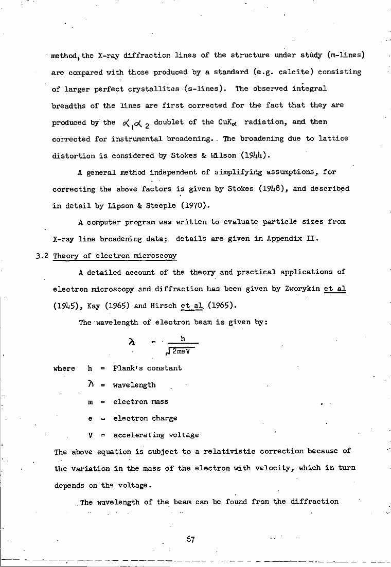
methodjthe X-ray d i f f r a c t i o n l i n e s of the st r u c t u r e under study (m-lines)
are compared i-rLth those produced by a standard (e.g. c a l c i t e ) consisting
of larger perfect c r y s t a l l i t e s ( s - l i n e s ) . The observed i n t e g r a l
breadths of the lines are f i r s t corrected f o r the f a c t t h a t they are
produced by' the o(, ^o(^ 2 doublet of the CuK^ r a d i a t i o n , and then
corrected f o r instrumental broadening. . The broadening due to l a t t i c e
d i s t o r t i o n i s considered by Stokes & Vfi.lson (I9UI1).
A general method independent of s i m p l i f y i n g assumptions, f o r
corre c t i n g the above factors i s given by Stokes ( l 9 l * 8 ) , and described
i n d e t a i l by Lipson & Steeple (1970).
A computer program was vn:'itten t o evaluate p a r t i c l e sizes from
X-ray l i n e broadening data.} d e t a i l s are given i n Appendix I I .
3.2 Theory of electron microscopy
A de t a i l e d account of the theory and p r a c t i c a l a p p l i c a t i o n s of
elec t r o n microscopy and d i f f r a c t i o n has been given by Zworykin e t a l
(19U5), Kay (1965) and Hirsch e t a l (1965)-
The wavelength of elect r o n beam i s given by:
h J~2meV
where h = Plank's constant
7 = wavelength
m = electron mass , .
e = electron charge
V = accelerating voltage
The above equation i s subject t o a r e l a t i v i s t i c c o r r e c t i o n because of
the v a r i a t i o n i n the mass o f the e l e c t r o n w i t h v e l o c i t y , which i n t u r n
depends on the voltage.
. The wavelength of the beam can be found from the d i f f r a c t i o n
67
p a t t e r n of a substance vrith fcnovm u n i t c e l l dimensions and c a l c u l a t i n g
a single f a c t o r , the camera constant, 7\ L, vjhere L i s the e f f e c t i v e
camera length.
Electron microscopy i s based e s s e n t i a l l y on the same p r i n c i p l e
as o p t i c a l microscopy TTith the difference t h a t the lens system of the
l a t t e r f o r the d e f l e c t i o n of the beams i s replaced by a combination of
magnetic or e l e c t r i c f i e l d s having d i f f e r e n t i n t e n s i t i e s and d i r e c t i o n s .
The magnifying power of the e l e c t r o n microscope i s considerably enhanced
due t o -the f a r shorter v/avelen'gth of the e l e c t r o n beam compared w i t h t h a t
of the v i s i b l e beam. The t h e o r e t i c a l l i m i t of r e s o l u t i o n , given by h a l f
the v/avelength of the r a d i a t i o n used, i s 0.022 f o r the e l e c t r o n micro
scope and 20002 f o r the o p t i c a l microscope.
A specimen i s studied by transmission microscopy by p u t t i n g i t i n
the f o c a l plane of the lens system and observing i t s enlarged image on
a phospihor screen or by recording on a photographic f i l m h e l d i n a
cassette w i t h i n the instrument. Usually, both f a c i l i t i e s are employed,
one t o a l i g n and select the image, the o-ther to record i t . As the
high energy electrons c o l l i d e w i t h gas molecules, they are dispersed
and t h e i r energy l e v e l i s considerably loijered. To avoid such c o l l i s i o n s
of electrons, the mean free path of the gas molecules i s increased by
decreasing the working pressure of the e l e c t r o n microscope t o about
lO"^ mm Hg. A special lens system i s used, by int e r p o s i n g between
objector and pro j e c t o r , to take d i f f r a c t i o n patterns of samples being
studied on the electron microscope. D i f f r a c t i o n micrographs are
obtainable only f o r very t h i n c r y s t a l s and aggregates or elements of
low mass number, ovring t o the high absorption of e l e c t r o n vjaves by
matter. The single c r y s t a l d i f f r a c t i o n p a t t e r n consists of r e f l e c t i o n s
•68-

from a plane of reciprocal l a t t i c e p o i n t s , cf-.X-rays. The d i f f r a c t i o n
p a t t e r n of a p o l y c r y s t a l l i n e substance i n random o r i e n t a t i o n consists
o f t y p i c a l concentric rin g s .
3-2.1 Apparatus
D i f f r a c t i o n and d i r e c t transmission micrographs of powdered
materials and transmission micrographs of surface replicas of sintered
r e f r a c t o r y materials f o r the present work were obtained using a
P h i l i p s EM 100 B model elec t r o n microscope (Van Dorsten, Nieuwdorf &
Verhoeff, 1950). I t has a reasonably good r e s o l u t i o n of 25S. The
pumping system of the microscope consists of a prevacuum r o t a r y pump,
a mercxiry d i f f u s i o n and an o i l - d i f f u s i o n pump. Micrographs of the
specimens are taken by means of a camera loaded w i t h 35 mm f i l m and
f i t t e d i n the microscope. The magnification i s c o n t r o l l e d by varying
the currents t o the electro-lenses. Various parts of the g r i d can be
observed by means" of controls f o r focussing and f o r moving the sample
holder. An image of the sample under observation i s thrown on the
fluorescent screen d i r e c t l y i n f r o n t of the observer. I n order t o take
a micrograph of the image on the screen, the camera i s lowered i n t o
p o s i t i o n and the shutter opened. The exposure depends upon the
i l l u m i n a t i o n of the image and may be up t o several seconds. The
magnification i s determined by reading a scale and then consulting
standard tables. A suitable area of the sample f o r a d i f f r a c t i o n micro
graph i s chosen by means of a d i f f r a c t i o n s e l e c t i o n diaphragmj the
d i f f r a c t i o n lens i s switched on and the intermediate lens switched o f f .
Longer exposures f o r d i f f r a c t i o n micrographs are required because of
t h e i r loi-rer i n t e n s i t y . When the e l e c t r o n microscope has s t a r t e d working,
samples can be r e a d i l y changed by removing the g r i d holder and i n s e r t i n g
69

another one c a r r y i n g a d i f f e r e n t sample. T h i s operat ion takes a f r a c t i o n
of a minute. The u s u a l voltage of e l e c t r o n microscope was ' 80kV.
Carbon and metal f i l m s were prepared i n a "Speedivac" High Vacuum
Coating Uni t 12 E 6 , manufactured by Edwards High Vacuum L t d . The main
p a r t of the u n i t i s a g l a s s work-chamber, evacuated by an o i l d i f f u s i o n
pump backed by a r o t a r y pump. E l e c t r i c c i r c u i t s , to s t r i k e an a r c across
carbon e l ec trodes and f o r the vapour depos i t ion of metal f i l m from a
f i l a m e n t , are f i t t e d i n s i d e the chamber. Var ious gauges f o r readings of
pressure i n s i d e the chamber and c o n t r o l s f o r the e l e c t r i c i t y supply to
the c i r c u i t s in s ide are f i t t e d on the pane l of the ins trument .
3.2.2 Preparat ion of samples
Microscopic s tudies of samples were made by s c a t t e r i n g the
p a r t i c l e s on a carbon f i l m supported on a copper g r i d . The t h i c k n e s s
of the carbon f i l m was of the order of 200S. The copper g r i d vjas of 3* mm
diameter and had a square mesh. The length of the s ide of square was
100M A' p a i r of forceps was used to handle the g r i d throughout the
i n v e s t i g a t i o n of specimens.
An e l e c t r i c arc v;as s t ruck between pure carbon e l e c t r o d e s i n the
high vacuum coating un i t f o r depos i t ing a carbon f i l m on a mica s u r f a c e .
The a r c vol tage and current were lOV and 60A r e s p e c t i v e l y . The a r c
was s t r u c k i n about e ight b u r s t s , wi th an i n t e r v a l of approximately 3
seconds between success ive b\ irsts to coo l iiie e l e c t r o d e s . The "pressure
in s ide the chamber vjas kept below 10~^mm E g .
The mica p la te was h e l d i n a s l a n t i n g p o s i t i o n a t an angle of
about 3 0 ° a t the surface of a s m a l l trough of water and the carbon f i l m
f l o a t e d o f f on the water s u r f a c e , by g r a d u a l l y lowering the p l a t e below
the water l e v e l u n t i l i t sank. The carbon f i l m i s s t r i p p e d o f f the
sur face of mica by water by v i r t u e of i t s sur face t e n s i o n . I t vzas
70

f a c i l i t a t e d by cut t ing ' o f f the edges of the mica sheet a f t e r depos i t i on
of the f i l m and contaminating the mica sheet by breathing onto i t before
depos i t ion . The f l o a t i n g f i l m was deposi ted on the copper g r i d and the
r e s i d u a l vzater absorbed by p l a c i n g i t on a f i l t e r paper. The g r i d so
prepared was p laced i n a v e r t i c a l c y l i n d r i c a l ho lder and locked i n
p o s i t i o n vri-th a c y l i n d r i c a l cap. The g r i d was exposed through the open
end of the cap, A d i s p e r s i o n of the m i c r o c r y s t a l l i n e powder was made
i n e i t h e r water or acetone, by keeping i t suspended i n a l iqx i id tank,
v i b r a t i n g a t the extremely high frequency of an u l t r o s o n i c u n i t f o r
about 20 minutes. A drop of the s i ispension was placed on the copper
g r i d c a r r y i n g the f i l m and was evaporated to dryness under an i n f r a
red lamp. Then i t was p laced i n a microscope g r i d h o l d e r , and i n s e r t e d
i n the e l e c t r o n microscope.
3.2.3 The r e p l i c a technique and shadow c a s t i n g
The sur face f ea tures of s o l i d s can be s tud ied i n minute d e t a i l s
by means of the r e p l i c a technique. I t i n v o l v e s the t r a n s f e r of a
surface topograiiiy of a s o l i d body to a t h i n f i l m which c a n be examined
by t r a n s m i s s i o n e l e c t r o n microscopy. The sur face d e t a i l s may be
sharpened by shadowing vrLth a heavy metal which absorbs e l e c t r o n s
s t rong ly . Carbon r e p l i c a s v/ith a shadow c a s t i n g of pa l lad ium metal
were prepared as f o l l o w s .
Polystyrene gra ins x-rere melted on a g l a s s s l i d e over a bunsen
burner . The s o l i d sur face of the s i n t e r e d sample was brought i n t o close
contact wi th the melt and pressed very gent ly onto i t . I t was then
alloT-jed to cool and s o l i d i f y . T h i s s o l i d i f i e d specimen, c a r r y i n g the
surface impress ion of the s i n t e r e d sample, was p laced i n the vacuiun u n i t
and deposi ted i-rLth a carbon f i l m as d e s c r i b e d above. I t was then
71

shadoi-jedj i . e . coated with a f i l m of pa l lad ium metal as f o L l o V s .
A t h i n pal ladium metal V 7 i r e , p l a c e d i n a tungsten ifilamerit'j was
evaporated by pass ing through i t a heavy c u r r e n t ; the metal was a l lowed
to depos i t on the f i l m r e p l i c a . The polymer was d i s s o l v e d away i n 1,2-
d i ch loroe thy lene . The remaining f i l m x^as p icked up on a copper g r i d ,
d r i e d under an i n f r a - r e d lamp and then .observed i n the e l e c t r o n m i c r o
scope. Before each evaporation operat ion , the f i l a m e n t was " f l a s h e d " ,
i . e . i t s temperature was r a i s e d to remove d i r t e t c . by pass ing a
s l i g h t l y h igher ciorrent' through i t than was subsequently used f o r meta l -
evaporat ion.
A f t e r completion of a s e t of exposures , the f i l m v;as removed from
the e l e c t r o n microscope camera and developed i n a f i n e g r a i n developer
to give optimum c o n t r a s t . Enlarged p r i n t s were made from the "negative"
onto Kodak bromide paper. I n t h i s manner magn i f i ca t ions o f over 70,000
times the o r i g i n a l were obtained.
3.3 Scanning e l e c t r o n microscopy
Comprehensive accounts of the theory of SEM and i t s s p e c i a l
a p p l i c a t i o n s are given by Thornton ( I 9 6 8 ) . A b r i e f s\immary of i t s
f e a t u r e s i s g iven below.
SEM c o n s i s t s mainly of three types of components:
1- E l e c t r o n - o p t i c a l column i n c l u d i n g e l e c t r o n i c s
A schematic diagram of the instrument i s shown i n f i g . 3.1.
The column comprises an e l e c t r o n gun and two to f o u r e l e c t r o n
l e n s e s . The e l e c t r o n beam pass ing through the system of
lenses i s demagnified i n diameter to 25o2 or l e s s . The f i n a l
lens assembly contains two s e t s of magnetic scanning c o i l s .
They are energized by a s u i t a b l e scan generator to d e f l e c t the
72

Chopping c o i l s
- J
E . H . T
Magriif ication contro l
> supplies
> •
Ampl i f i ers
Scanning c o i l s
Astigma
Specimen b ias
Specijne
Vacuum sysxem E l e c t r o n -c o l l e c t o r
Light detector
Intensity-modulated CRT's
o cn Ha H -
CO (i>
Luminescent
Emiss ive
Conductive
'Linescan* d i sp lays
beam on the specimen siarface i n a r a s t e r - l i k e p a t t e r n . The
e l e c t r o n coliimn contains three more items: ( i ) A s e t of
apertinres f o r s p e c i f y i n g the angular aperture subtended by
the beam a t the specimen s i i r f a c e . ( i i ) An ' a s t i g m a t ' ,
c o n s i s t i n g of a s e t of c o i l s of s p e c i a l des ign to overcome
any ast igmatism i n the system., ( i i i ) A s e t of 'chopping'
c o i l s or p l a t e s f o r superimposing modulation on the e l e c t r o n
beam.
2 . Vacuxim system, specimen chamber and stage
Vacuum i s maintained i n the e l e c t r o n column and specimen
chamber by a pumping system. The specimen stage i n the
chamber has the f a c i l i t y to move the specimen i n the e l e c t r o n
beam and examine a t a d e s i r a b l e angle to the beam. The i n t e r
a c t i o n of the e l e c t r o n beam wi th the specimen g ive s r i s e to
e f f e c t s l i k e secondary e l e c t r o n emiss ion , a r e f l e c t e d e l e c t r o n
curreni^ be am-induced conduction and o f ten cathodoluminescence.
3 . S i g n a l detec t ion and d i s p l a y system
The s i g n a l s can be deduced and a m p l i f i e d to c o n t r o l the
v i s i b i l i t y of the bank of cathode-ray tube ( C R T ) . The
s p e c i f i c a t i o n of spot p o s i t i o n i n CRT and the primary beam
on the specimen surface i s f a c i l i t a t e d by the same scan
generator . Usxially the s i g n a l i s f ed to the br ightness c o n t r o l
of a cathode-ray tube vfith a long p e r s i s t a n c e phosphor f o r
v i s u a l examination. S i g n a l can f i i r t h e r be d i s p l a y e d on a tube
w i t h s h o r t - p e r s i s t a n c e phosphor f o r photographic r e c o r d s . The
synchronism of cathode-ray tubes v/ith pirlmary beam i s mani
f e s t e d by the scan generator c o n t r o l l i n g the m a g n i f i c a t i o n .
I t s output i s introduced to the d e f l e c t i o n c o i l s of the CRT
to keep the r a s t e r s i z e approximately 10 X 10 cm. The r a s t e r

s i z e on specimen i s smal l er than t h i s . I n g e n e r a l terms i f
the specimen r a s t e r i s 10A( X lOM i n one c a s e , \and IXlmmjin
another wi th a c e r t a i n vo l tage , then the m a g n i f i c a t i o n i s XIO^
2
i n the f i r s t and XIO i n the second c a s e .
A d d i t i o n a l e l e c t r o n i c equipment c o n s i s t s of the h i g h - s t a b i l i t y
supply f o r the e l e c t r o n gun, the h i g h - s t a b i l i t y c u r r e n t supp l i e s f o r the
magnetic l e n s e s , the contro l systems f o r the cathode-ray tubes , the
a n c i l l a r y equipment associated Tirith the v a r i o u s s i g n a l detection systems
and monitoring systems.
For SEM^ samples are simply motinted on the microscope stage and
vacuum coated Vfith aluminium to ensure good e l e c t r i c a l c o n d u c t i v i t y and
are then p laced i n the microscope. The Cambridge Stereoscan S^- lO wi th
a r e s o l u t i o n o f be t ter than 100 S v/as used f o r s tudy of metal f o i l s
(Chapter 6). The instrument i s s i t u a t e d a t The R o y a l Naval E n g i n e e r i n g
C o l l e g e , Manadoni Plymouth.
3'h Thermoanalyt ica l techniques
Of the var ious a n a l y t i c a l techniques known as thermometric a n a l y s i s ,
two are most commonly i n use- F i r s t , thermogravimetry ( T G ) wherein the
freight change of the sair5>le under i n v e s t i g a t i o n i s fo l lovjed over g iven
periods of time and the temperatxire can be v a r i e d a t any d e s i r a b l e r a t e .
I t i s s p e c i f i c a l l y u s e f u l f o r studying the r e a c t i o n s of s o l i d s i n v o l v i n g
a change of weight. The atmosphere of the m a t e r i a l under study may be
c o n t r o l l e d , e . g . an i n e r t or r e a c t i v e atmosphere may be used.
The thermobalance used was a modif ied v e r s i o n of a double pan
a n a l y t i c a l balance (Gregg & Windsor, 19ii5). I n the c u r r e n t r e s e a r c h
programnB, a Stanton Model Ah9 balance was used , s e n s i t i v e up to weight
changes of 10"^g. One pan of the balance was f i i r n i s h e d , on i t s unders ide ,
wi th a hook c a r r y i n g a length of nichrome w i r e . The wire passed through a
hole i n the balance s h e l f and supported a s i l i c a sample bucket , which was
suspended i n an e l e c t r i c furnace c o n t r o l l e d by a Stanton-Redcrof t l i n e a r • : 75

programmer. The measurement of temperature i n the v i c i n i t y of tiie
sample vas made by means of a chromelalumel thermocouple p l a c e d c lose
to the sample bucket and attached to a m i l l i - v o l t m e t e r ( B a i r d &
T a t l o c k - R e s i l i a ) .
Varying amounts of samples, 0.5 - 2.5 g, x-rere weighed a c c u r a t e l y
i n t o an aluminium c r u c i b l e (Thermal Syndicate Thermel Alumina) . The
weight change i n the samples vxere follox-red a t known i n t e r v a l s of t ime.
I n the present x-jork, k i n e t i c and heat treatment s t u d i e s xrere c a r r i e d out
x/ith a i r as the r e a c t i n g medium. The k i n e t i c behavioiur of the v a r i o u s
r e a c t i o n s was fo l lowed by r e g r e s s i o n a n a l y s i s ( l e a s t square f i t ) over
given periods of t ime.
The second commonly used method f o r thermometrie a n a l y s i s i s
d i f f e r e n t i a l thermal a n a l y s i s ( D T A ) , f i r s t developed by Houldsvxorth &
Cobb (1922). The t e s t and i n e r t m a t e r i a l s had embedded i n them separate
thermocouples vjhich were connected a t t h e i r opposite ends. T h i s a r r a n g e
ment enables the measurement of emf produced dur ing the t r a n s f e r of heat
during the r e a c t i o n p r o c e s s , and temperatures a t which such changes take
p lace . Throughout the present r e s e a r c h work, apparatus based on the
design descr ibed by Grimshaw, Heaton Roberts (19U5) was used.
0.5 - 1.5 g of the samples xjere p laced a longside the re ference
m a t e r i a l , r e c r y s t a l l i z e d alumina i n a ceramic b l o c k . T h i s was heated
i n an e l e c t r i c furnace ( G r i f f i n and George) a t a l i n e a r l y - c o n t r o l l e d
ra te of 10 to 20°/min. by means of a l i n e a r programmer ( S t a n t o n - R e d c r o f t ) .
An automatic recorder i n d i c a t e d the temperature of the block as x j e l l as
the* heat change over the temperature range of 250° to lOOO^C, i n order to
determine the tenqjerature requ ired f o r Uie onset of the r e a c t i o n .
3.5 Surface area measurement by gas s o r p t i o n
T h i s method of surface a r e a measurement depends on the f a c t t h a t t>i«
76

quant i ty of a gas adsorbed on the s i i r face of a m a t e r i a l i s a . f u n c t i o n
of the s p e c i f i c s u r f a c e , i . e . the sur face a r e a per un i t mass. From the
s p e c i f i c s u r f a c e , the average c r y s t a l l i t e s i z e may be e s t imated f o r
powders having c r y s t a l l i t e s of approximately uniform shape and simple
geometry. Glasson (1956 and 1958) and Gregg & Sing (196?) have g iven
d e t a i l e d d e s c r i p t i o n s of the method.
To obtain the monolayer c a p a c i t y , x^, from the adsorpt ion
i sotherm, the most commonly used method i s tha t given by Brunauer,
Emmett and T e l l e r (1938). According to the B . E . T . e q u a t i o n : -
P = c - 1 . ^ + ( i ) x ( p ° . p ) x^c p ° x^c
where: p = pressure of adsorbate vapour i n e q u i l i b r i u m w i t h
absorbent.
p ° = saturated vapour pressure of vapour adsorbed.
X e amount of vapoiir adsorbed,
x^ = capac i ty of f i l l e d monolayer,
c = constant .
There are f i v e main types of the adsorpt ion isotherms as c l a s s i f i e d
by Brunauer, Demming, Demming & T e l l e r (19U0) (commonly r e f e r r e d to a s
the B - E . T . c l a s s i f i c a t i o n ) . Types I I and IV are i n good agreement with
the B . E - T . equation f o r determing the s p e c i f i c surface of subs tances ,
whi le type IV i s appl icable f o r the determination of the pore s i z e
d i s t r i b u t i o n . Hoi-jever, type I I g ives best agreement v/ith the B . E ^ T .
equation over l i m i t e d ranges of r e l a t i v e vapour pressure (Gregg, 1961).
A p l o t of p VS p g ives a s t r a i g h t l i n e with c - 1 as s lope and
x ( p ° - p) p° x^c
1 as i n t e r c e p t . Values of c and x can be c a l c u l a t e d from these two
m
77

parameters . The l i n e a r i t y of the r e l a t i o n s h i p between p / x ( p ° - p ) and
p / p ° a p p l i e s only between va lues of p / p ° from 0.05 to about 0 . 3 . The
amount of gas adsorbed oan be determined e i t h e r g r a v i m e t r i c a l l y or
v o l u m e t r i c a l l y (Gregg & S ing , 196? p . 3 1 0 ) .
s h i p :
The s p e c i f i c s u r f a c e , S , v a r i e s w i th x^ according to the r e l a t i o n -
S X N. A m. m M • •
where s M = molecular vjeight of adsorbate .
N = Avogadro's number.
A = C r o s s - s e c t i o n a l a r e a of an adsorbate molecule i n a m
completed monolayer.
From the s p e c i f i c surface ( S ) o f a powder, the average c r y s t a l l i t e
s i z e , 1, assuming that a l l the p a r t i c l e s are s p h e r i c a l , can be determined
e a s i l y .
P= d e n s i t y of the s o l i d (adsorbent ) .
T h i s r e l a t i o n s h i p i s app l i cab le f o r p a r t i c l e s of cubic shape a l s o .
Express ions f o r the other shapes, ( e . g . p l a t e - and needle-shaped p a r t
i c l e s ) can be der ived e a s i l y .
3-5.1 The apparatus
The sorpt ion balance developed by Gregg il9h6y 1955) has been used
throughout i n the present work. Uie g l a s s beam of the s o r p t i o n balance
i s .supported on saphire needles , which are put i n t o a g l a s s c r a d l e . One
arm of the balance c a r r i e s a bucket f o r the sample w i t h counter-weights ,
and the other c a r r i e s a so lenoid or magnet enclosed i n a g l a s s envelope
surrounded by an e x t e r n a l so leno id . The whole balance i s enc losed i n a
78

g l a s s case and other a c c e s s o r i e s l i k e vacuum pumps, gauges, and gas
r e s e r v o i r s are connected to i t . The g l a s s case can be evacuated and
f i l l e d with any des i rab le gas . D e s c r i p t i o n s of the sorpt ion balance
and the loi-7 temperatujre n i trogen soirption method are given by Gregg
(19ii6) and Glasson (1956) . The technique i s now an e s t a b l i s h e d
one f o r the determination of p a r t i c l e s i z e (BSii359, p a r t I 1969) .
3 . 5 « 2 Measurement of sorpt ion isotherms
The samples f o r s p e c i f i c sur face s t u d i e s xjere outgassed i n the
specimen bucket to remove adsorbed vapours and moistxire on t h e i r s u r f a c e s .
The temperature of the specimen was maintained a t 2 0 0 ° by surrounding the
g lass limb vrith furnace during t h i s operat ion (Glasson , 196i i ) . Nitrogen
i s maintained by b o i l i n g l i q u i d oxygen coo lant contained i n a Dev/ar f l a s k ,
The i n i t i a l weight of samples was determined i n vacuo, fo l l owd by
addi t ions ("dosing") o f ni trogen i n t o the apparatus- Observat ions of
sample vreight versus corresponding n i t rogen gas pressures v/ere taken
under condi t ions of e q u i l i b r i u m . To determine the desorpt ion s e c t i o n of
tiie i sotherms, sample weights were recorded a t decreas ing e q u i l i b r i u m
ni trogen pressxares, when insta lments of n i t r o g e n were pumped out of the .
ba lance .
The weight correc t ions f o r buoyancy e f f e c t s of the sample and
conta iner had to be app l i ed to a l l vjeight changes. Such c o r r e c t i o n s
were determined from experiments c a r r i e d out under the same condi t ions
wi th s a u r i e s of knovm X - r a y dens i ty and n e g l i g i b l e surface a r e a . The
quarter-mill igramme s e n s i t i v i t y of the vacuijm balance gave an accuracy
2 -1 of + 0 .1 m g on 10 g samples, l ead ing to p o s s i b l e e r r o r s of over 3%
2 1
where the s p e c i f i c s u r f a c e , S , <C 3 m-g" . The remaining d e t a i l s of the
technique are b a s i c a l l y s i m i l a r to those descr ibed i n the o r i g i n a l paper
79

i n v o l v i n g xise of a vacuxam balance f o r low-tenperature s u r f a c e a r e a
determination (Glasson , 1956).
. Thus, the l i q u i d oxygen bath remained constant w i t h i n + 0.2° and
a t l e a s t I h was allox-:ed f o r the sample to a t t a i n a constant temperatxire.
I n p r a c t i c e , the sample i s g e n e r a l l y up to about 1° warmer than the
l iqxi id oxygen outside the balance l imb (as i n d i c a t e d by i n t e r n a l and
e x t e r n a l thermocouples). The sample shows a temperature constancy
s i m i l a r to t h a t of the bath(+ 0 .2°) , and dependent to some extent on the
s i z e s of the sample conta iners and hangdoxm tubes (up to 30 mm d i a m e t e r ) ,
depth of immersion i n the l i q u i d oxygen (over 15 cm) and p o s s i b l y on the
surroxinding ni trogen gas pres sure . By s tandard i s ing the eqxiipment and
improving the heat i n s u l a t i o n a t the top of the Dewar f l a s k , the sample
temperature vras kept w i t h i n + 0.1°, thereby minimising the v a r i a t i o n i n
the s , v . p , of the n i trogen to preserve an accuracy of b e t t e r than 3% i n
the sur face area- determination.
The oxygen isotherms, which extended to a r e l a t i v e p r e s s u r e , p / p ° ,
near u n i t y , exh ib i ted l i t t l e or no h y s t e r e s i s a t p / p ° < 0.3. From these
and the ni trogen isotherms, S could be c a l c u l a t e d by the B . E . T . procedure,
us ing values of l i i . l S and 17.0 f o r the c r o s s - s e c t i o n a l a r e a s , A ,
of oxygen and of ni trogen r e s p e c t i v e l y ; t h i s gave agreement w i t h i n c a
5% i n the va lues of S obtained from both s e r i e s of" i sotherms. The
o lder g r a p h i c a l and newer computer (with l i n e - p l o t t e r ) methods ( O ' N e i l l ,
1969) agreed w i t h i n + 1% f o r values of S from each ind iv idx ia l i so therm
(Glasson & L ins t ead-Smi th , 1972),
3.6 S i n t e r i n g o f m a t e r i a l s
The s i n t e r i n g of boron carbide xjith and v:ithout d i f f e r e n t
addi t ives xjas c a r r i e d out i n argon as w e l l as i n vacuum.
80

I n i t i a l l y a high temperature furnace P . C . I O (Metals R e s e a r c h ,
Cambridge) vxas used f o r s i n t e r i n g f i n e l y - d i v i d e d boron carbide vrith
metal a d d i t i v e s . A f t e r some c y c l e s of heat ing f o r the s i n t e r i n g of
boron carbide vri.th aluminium up to 1 ,800°C, the inner tiibe of the
furnace f a i l e d . I n v e s t i g a t i o n in to the cause of f a i l x i r e l e d to the
fo l lowing explanat ion . Aluminium, being v o l a t i l e a t such high temper
atures (m.p. 659.7°C b . p . 2 ,057^C) , evaporates and r e a c t s w i th the
alumina of the tube to give A l O . The l a t t e r i s a much more v o l a t i l e
oxide and i t s formation and evaporat ion mechanica l ly weakens the tube
a t high temperatures. A f t e r replacement of the tube and element i n the
P . C . I O f u r n a c e , a second s t a r t was made vri.th i r o n as the a d d i t i v e to
boron carbide. . The furnace again f a i l e d , t h i s time due to a t e c h n i c a l
f a u l t i n the manufacture of the element. A t h i r d s t a r t was made w i t h
i r o n as a d d i t i v e , but t h i s was fo l lowed t y a tube f a i l u r e which l e d to
complete^, c losure of t h i s furnace and never vjas i t used again i n t h i s
work. I n v e s t i g a t i o n by Metals Research engineers suggested the incompat
i b i l i t y of boron carbide w i th alumina. However,, boron carbide was heated
with r e c r y s t a l l i s e d alumina from c r u c i b l e s a t 2,000'^C l a t e r i n t h i s work,
but X - r a y a n a l y s i s showed no r e a c t i o n between the components. T h i s
alumina was found to be i n o< - and H - forms , which may account f o r i t s
mechanica.1 i n s t a b i l i t y tovmrds thermal shock.
3.6.1 Cons truc t ion of High Temperature Furnace
A f t e r these mishaps, a vacuum furnace was c o n s t r u c t e d . F i g . 3 - 2 .
being pox-rered by a foiu* foLlwatt radiofrequency induct ion heater (Delap-
ena E h kV/) with i i ie wound c o i l e x t e r n a l to a' 1 i n . diameter alumina
tube. The tube vzas evacuated by a s i n g l e stage r o t a r y pump (Edwards
Speedivac I S 150) backing a two stage o i l d i f f u s i o n pump (Edwards
Speedivac ii03A). Vacua of betvjeen 10" to 10~ mm Hg were ach ieved .
81

F i g . 3.2 High temperature vacuum furnace of s i n t e r i n g s tud ie s
O p t i c a l pyrometer
S i l i c a sheath
C r u c i b l e
R . F . c o i l
Vacuum gauge
D i f f i i s i o n pximp
Rotary vacuum pump
Opt ional
^ Gas i n l e t
82

A f t e r s e v e r a l f a i l u r e s , the alumina tubes were rep laced by fused
s i l i c a tubes (Thermal Syndica te ) having b e t t e r thermal shock r e s i s t a n c e .
However, the s i l i c a tubes can only be heated to between 1 , 0 0 0 ° and l,iiOO°C
and f o r l i m i t e d times to avoid extens ive r e c r y s t a l l i s a t i o n and c r a c k i n g
when cooled. Contact had to be avoided between the s i l i c a tubes and
the graphite c r u c i b l e s f o r the induc t ion h e a t e r .
. I n order to v;ork a t temperatures between 1 , 0 0 0 ° and 2 , 0 0 0 ° C ,
alumina tubes were re introduced i n a modif ied form. Two tiJbes vrere . V -
placed end to end i n the h o t t e s t p a r t of the i n d u c t i o n f u r n a c e , as
shotm i n F i g . 3 -2 . . T h i s arrangement minimised mechanical s t r a i n
caused by thermal shock, y e t o f f ered thermal r e s i s t a n c e to heat r a d
i a t e d towards the w a l l s of the outer tube. The inner tubes were kept
v e r t i c a l by a t tach ing t h e i r f a r ends to asbestos shee t s , the top shee t
a l so c l o s i n g the end of the outer tube. The c r u c i b l e was supported on
an alumina pedes ta l standing on the bottom of the outer tube. The
height of the pedes ta l was approximately t h a t of the l ength of the l o w r
inner tube so that the c r u c i b l e r e s t e d near the j u n c t i o n o f the two inner
tubes,, surrounded by the copper c o i l f o r R . F . i n d u c t i o n h e a t i n g . The
upper p a r t s of the apparatus were sea led w i t h Kos aluminous cement
covered a l s o by rubber s e a l s to ensiire a i r - t i g h t n e s s . P o r o s i t y t o argon
was e l iminated by coat ing the cement and asbestos i-/ith a imiform t h i c k
l a y e r of aluminium p a i n t . The reading of temperature by a d i sappear ing
f i lament o p t i c a l pyrometer ( F o s t e r ) was f a c i l i t a t e d by having a g l a s s
window fas tened by a riibber s e a l to the upper end of the inner tube .
The main f ea tures of t h i s furnace a r e : -
( a ) I t s design enables i t to be r e s i s t a n t to thermal shock, p os s
i b l y t o l e r a t i n g lox-rer grades of oC-Al^O^ f o r the tubes . Samples
83

can be heated up to 1,800°C i n 5 minutes and cooled back
to working temperature i n l5 minutes; c f . t h e P . C . I O
furnace which requ ires three hours f o r s i m i l a r heat ing c y c l e s .
(b) The sample can be seen throiJgh a g l a s s window a t a d i s tance of
' 6 i n s . from i t , and photographic methods could be used to
fol lovj the course of r e a c t i o n s .
(c ) I t i s more economic to run and does not need a f l o w of 90^
nitrogen-10^ hydrogen, as req idred by the Molybdenum viindings
of the P . C . I O furnace .
(d) I t - c a n . b e modified f o r s i n t e r i n g vrork a t h igher temperatures ,
up to 2,500°C using magnesia t h o r i a tubes
3.7 React ion s i n t e r i n g of boron carbide vrlth metals by hot p r e s s i n g
Three hot pres s ing f a c i l i t i e s were used f o r t h i s work.
3.7-1 Laboratory ho t -pres s ing system
A smal l s c a l e laboratory h o t - p r e s s i n g system ( F i g . 3*3) was s e t up
to inves t iage the pressi ire s i n t e r i n g p r o p e r t i e s of s m a l l q u a n t i t i e s
(lOg) of poi-jders. The system i s based upon a double -ac t ing mechanical
p r e s s , designed by Roeder and Scholz (1965), capable of working a t
temperatures up to 3,200°C and pressures up to 1,000 kg cm~^. The
r e s i s t a n c e - h e a t e d graphite die s e t i s h e l d between water-coo led copper
e l e c t r o d e s , the pox-rer being suppl ied by a 60 Id-7 s i n g l e phase transformer
which can d e l i v e r up to 3,000 A a t 207; the o r i g i n a l des ign employed a
smal l er (2ii }^J) transformer. Since the e l e c t r i c a l r e s i s t a n c e of the
die i s i n v e r s e l y proport iona l to i t s c r o s s - s e c t i o n a l a r e a , the h i g h e r
povjer a v a i l a b l e from the l a r g e r transformer w i l l enable d i f f e r e n t d i e
( and hence sample) geometries to.be i n v e s t i g a t e d .
The poorer suppl ied to the transformer i s r egu la ted by means o f a

F i g . 3-3 Laboratory hot pres s ing system
P i s t o n
/ / / / / / / v z z z : ' / / / / / / / / / / / /
[ — I '2ZZ2ZZZZZ^. 'yy,\
'22zzzzzzzzz^^ CooLing water
z z z a yyyy/yyyy>w^
P i s t o n
liUUUU
/ T Y T T r r n n T r a n s f onner
iUiO-v Input
I
I s o l a t o r svxitqh
y
T = T h y r i s t o r
F = F i r i n g c i r c u i t
V = T r a n s i e n t voltage protectors
r I
^ | _ V W V \ A / V « 1 J
Potentiometer
85

t h y r i s t o r control system designed by Biddulph (1972) and fxirther
developed during the present work. The b a s i c c i r c u i t c o n s i s t s of ti-io
t h y r i s t o r s connected i n inverse p a r a l l e l , mounted on a water-cooled
copper busl^ and i s regulated by a f i r i n g c i r c u i t . The f i r i n g c i r c u i t
incorporates a potentiometei^ the adjustment of vrtiich provides a d i r e c t
c o n t rol of the power supply. T h y r i s t o r c ontrol of r e s i s t a n c e heating
i s preferred to the conventional s a t u r a t i o n reactor type since a more
precise regulation of the sample temperatures can be achieved.
3.7-2 I n d u s t r i a l hot-pressing systems
Samples 'of borides and carbides x-jere hot-pressed a t Bullock
Diamond Products Laboratories, Torpoint, using a graphite mould s e t
bet^-reen hydraulic rams and heated to temperatures lov^er than the melting
point of the respective samples, by a 36 kW R.F. induction heater (Wild-
B a r f i e l d ) , F i g . 3.U. The heat of the die s e t was contained by carbon
black powder ( c h a r c o a l ) ; ' The temperatxjre and pressixre were "increased
continuously (up to approximately 100 - ISO^C below the m.p. of the
sample) u n t i l the two rams had moved c l o s e r to each other by a pre-
calculated distance. This c a l c u l a t i o n was based on the t h e o r e t i c a l dens
i t i e s . Hot-pressed samples of up to 80% t h e o r e t i c a l d e n s i t y vrere
prepared. A disappearing filament pyrometer (Foster Instrument) was used
fo r temperature measurement-* A f t e r completion of hot p r e s s i n g the
whole assembly was allox^red to-cool, before being dismantled t o remove
the samples. These v;ere t e s t e d f or chemical composition, phase compos
i t i o n and mechanical p r o p e r t i e s .
Samples of CaB^ vjere hot pressed a t Borax Consolidated Research
Centre .(Chessington). Rams 35-5 - UO.6 cm long and 2.5ii cm i n diameter
were used to press the specimens i n a s p i r a l d i e . • The progress of
d e n s i f i c a t i o n was followed by noting the movement of a plunger as iJ\e
86

F i g . 3.U Hotpressing s e t up for conipaction of boron carbide
©
'///
////// /////
B
O O o o S
/////
H = Hydraulic ram R = R.F. c o i l G = Pressure gauge A = Asbestos s h i e l d I = Ram-travel i n d i c a t o r D = Graphitedie C = Carbon black P = O p t i c a l pyrometer B = Boron carbide S = Sighting tube .
87

temperatxjre and pressure were r a i s e d .
3-8 Hardness t e s t i n g of coatings
3.8.1 Moxinting of sample
Hardness t e s t s were performed on the surfaces of metal f o i l s
reacted with boron carbide a t temperatures 1,000°C - 1,800°C. Some of
the specimens were mounted on s y n t h e t i c r e s i n i n the sample mounting
machine. The sample was placed a t the centre of the bottom of mould
and covered with approximately 30 cm^ of B a k e l i t e . Heating was switched
on to cure the Bakelite and pressure was exerted on i t slowly and 6 -2
s t e a d i l y up to 1.37 x 10 Mm" u n t i l i t re t a i n e d shape f o r a few minutes, 6 2
The pressure vxas then r a i s e d to 2.75 x 10 Nm" and kept constant f o r
fi v e minutes. The heater was switched o f f , the sample cooled by a flow
of water f o r f i v e minutes and then taken out of the mould.
A l t e r n a t i v e l y some samples viere mounted on co l d s e t t i n g r e s i n .
Cold s e t t i n g r e s i n , 'metset r e s i n »SW'>(Metallurgical S e r v i c e s Ltd.)
was mixed vjith 'metset hardner' i n the r a t i o of 1 drop of hardner to
5 cm- of r e s i n i n a p l a s t i c container and s t i r r e d to ensure homogeneity.
The samples were placed at" the centre of the moulds and f i l l e d with t h i s
s e t t i n g mixture. They were l e f t overnight f o r s e t t i n g on-an even surface
and taken out from the moulds the following morning.
3.8.2 P o l i s h i n g
Mounted specimens were polished by grinding on d i f f e r e n t grades of
s i l i c o n carbide paper, f i x e d on smooth dovrnward s l a n t i n g g l a s s p l a t e s . A
continuous flow of water vjas spread evenly on the paper t o ensure wetting
during the grinding. Samples were ground on varying grades of rough and
smooth papers i n the order "Roughes minor" No. 220, No. 320, No. kOO and
f i n a l l y No. 600 (Strues S c i e n t i f i c Instruments).
A l t e r n a t i v e l y some specimens xvere polished on an automatic or
a hand pol i s h i n g machine. The specimens, a f t e r p o l i s h i n g , were x-fashed, 88 •

d r i e d and tes t e d on a Hardness Tester .
3.8.3 Projection microscope and inLcrohardness t e s t i n g equipment
. Detailed d e s c r i p t i o n of the equipment i s given by Troughton &
Sinnns (1956). A b r i e f account of i t s important f e a t i i r e s i s given below.
The assembly c o n s i s t s of a p r o j e c t i o n microscope and i s designed
f o r microscopic examinations and photography of:
.1. Opaque objects using (a) normal i n c i d e n t i l l u m i n a t i o n v/ith a
p l a i n glass r e f l e c t o r y (b) i n c i d e n t i l l u m i n a t i o n with a
me t a l l i c r e f l e c t i o n ; - ( c ) dark f i e l d i l l u m i n a t i o n ; (d) polar
i z e d l i g h t ; (e)'phase-contrast; and ( f ) normal i n c i d e n t and
oblique i l l u m i n a t i o n .
2. Translucent objects using (a) transmitted l i g h t ; (b) p o l a r
ized l i g h t ; ( c ) phase-contrast; and (d) transmitted l i g h t
Other f a c i l i t i e s include Micro Hardness Tester, equipment f o r surface
topography and u l t r a - v i o l e t l i g h t . Present work in v o l v e s study of
opaque surfaces and t h e i r hardness values. A b r i e f d e s c r i p t i o n of Micro
Hardness Tester i s given below.
3.8.3-1 Micro Hardness T e s t e r
A Vickers pyramid diamond whose faces have been worked to an
angle of 136 i s embedded i n the outer o p t i c a l surface of the microscope
objective, thus the area to be t e s t e d could be selected-and the indent
made and evaluated i-rLthout the interchange and exact r e g i s t r a t i o n of
indenter and objective. The load may vary from 0.1 to 500 g depending
on the specimen hardness. A load of 20 g was used throughout the present
work. The specimen was secured to one end of an a c c u r a t e l y balanced'
leve r and weight was applied to platform above the specimen. The
combined objective and diamond indenter vrere advanced tcr^ards the s p e c i -
89

men by means of the slov: motion foc\issing adjustment of the microscope
and contact vas indicated by the s i g n a l lamp. The measurement of the
impression was made with the a i d of the F i l a r Eyepiece, Microhardness
was read d i r e c t l y from standard t a b l e s .
3.9 Computer programming
Computer programs were x-zritten f o r various c a l c u l a t i o n s c a r r i e d
out i n the course of t h i s work. One of these has been dis c u s s e d
already i n connection \j±ih X-ray Une broadening (Section 3-1-U and
Appendix I I ) .
Thermodynamic parameters, i . e . fre e energy change, heat of r e a c t i o n
and equilibrium constants f o r various methods of production of borides
have been computed from the equations given by Schick (1965). Thermo
dynamic functions for reactions vjhere the constants are not known, have
been c a l c u l a t e d from table v a l u e s . A program f o r computing free energy
change, heat of reaction and equil i b r i u m constant a t various temperatures
i s given i n Appendix I I , together with specimen output f o r the r e a c t i o n :
Ti02 + 2B + 2C = TiBg + 2C0
The computed values have been plotted as Ellingham diagrams using a
graph p l o t t e r and a modified v e r s i o n of an e x i s t i n g program. T h i s
modified program i s given i n the Appendix.
F r a c t i o n a l volxime changes (Chapters U, 5 and 6) for conversion
of metal to boride (and carbide) and then.to oxide have been computedL/or
a l l knovm borides and carbides. The program i s given i n Appendix IV,
together vjith an output sample.
Complete outputs and programs w r i t t e n f o r c a l c u l a t i o n s during
t h i s work are av a i l a b l e i n a separate f o l d e r from Plymouth Polytechnic
L i b r a r y .
90
PART I I
T H E S I "S
Chapter h
Chapter 5
Chapter 6
Chapter 7
Chapter 8
R e a c t i v i t y and s i n t e r i n g of boron carbide
with metal powder a d d i t i v e s •
E f f e c t of a d d i t i v e s on the hot pressing of
boron carbide
The formation and microstructiure of boride
and carbide coatings on metal s i i r f a c e s
Oxidation of boron carbide
Concluding summary
91

CHAPTER I V
REACTIVITY AND SINTERING OF BORON CARBIDE WITH METAL FOVJDER ADDITIVES
11.1 Introduction
Previous researchers (Jones, 1970) have described the production
of boron carbide and shoxired hovi the s i n t e r i n g was a c c e l e r a t e d by
chromium metal povjder additive (Classen & Jones, 1969) . - The s i n t e r i n g
was accelerated markedly only a t higher temperature, ca. 1800?:. The
metal completely vjetted the boron carbide surface (Hamijan & Lidman,
1952). Some g r a p h i t i s a t i o n of carbon was noted at t h i s temperature;
t h i s could have l e f t some boron i n s o l i d s o l u t i o n with the remaining-,
boron carbide or chromium, but no zone of i n t e r a c t i o n producing c r y s t a l
l i n e chromium boride or carbide was found. T h i s behaviour of chromium
contrasts with that of i r o n xvhich forms zones of i n t e r a c t i o n when i t
accelerates the s i n t e r i n g of boron carbide. Other t r a n s i t i o n metals,
e.g. Co and Ni, give s i m i l a r zones, apparently c o n s i s t i n g of boride and
carbide a l l o y s of the corresponding metals.
I n the present research the e f f e c t s of i r o n and s e v e r a l other
metal powders on the s i n t e r i n g of the boron carbide are examined and
compared with one another. Possible compoiind formation during the
sintering"processes i s investigated a t a s e r i e s of temperatures between
1 0 0 0 ° and 1800°C.
11.2 Experimental
l i . 2 . 1 Materials 2 -1
The boron carbide used had a s p e c i f i c surface of 20 .6 m g-
corresponding to an average c r y s t a l l i t e s i z e (equivalent s p h e r i c a l
92

diameter) of 0.106// m. Portions of the m a t e r i a l were mixed vrith
knoxm amounts of povjdered metal a d d i t i v e s of s i z e g e n e r a l l y iM.m;
occa s i o n a l l y metal hydride powders, e.g. titanium and zirconium^were
used as a d d i t i v e s .
U.2.2 Procedure
The samples v/ere c a l c i n e d for f i x e d times u s u a l l y 5 hours i n vacuo
a t lOOO^C and argon at 1000°, 1200°, IhOCP.,- 1600° and 1800°C. The
s p e c i f i c surfaces of the cooled samples were determined by the B.E.T.
method (Brunauer, Emmettfic T e l l e r : , 1938) from nitrogen sorption isotherms
recorded a t -l83c on an e l e c t r i c a l sorption balance (Glasson, 1956 and
196U).
The amoxmts of metal additive vrere normally 1% and 10% by vreight
of boron carbide. Although these amounts often a c c e l e r a t e d s i n t e r i n g
considerably, they were i n s u f f i c i e n t to give complete X-ray patterns of
a i ^ metal borides or carbides formed. Thus, i t was necessary to compare
separately heated mixtures, containing l a r g e r amounts of metal a d d i t i v e ,
generally i n stoichiometric amounts required f o r complete metal boride
and/or metal carbide formation. These experiments were c a r r i e d out and
the r e s u l t s are discussed belca-j. •
li.2.3 Results
The v a r i a t i o n s i n s p e c i f i c surfaces of the s i n t e r e d boron carbide
samples are shown i n F i g s , i i . l - i i . 9 , where they are compared with the
average c r y s t a l l i t e s i z e s (eq\2ivalent s p h e r i c a l diamters) c a l c u l a t e d
from the s p e c i f i c surfaces and the X-ray d e n s i t i e s of the products.
Tables U.l - U.9 show the main metal boride and carbide phases formed a t
di f f e r e n t temperatures.
Decreases i n the number of c r y s t a l l i t e s during the 5 hour s i n t e r i n g s
93

of boron carbide vrith d i f f e r e n t metal a d d i t i v e s a t 1800°C i n argon are
compared i n Table ii . l O . The multiple changes are c a l c u l a t e d from the
r a t i o (S-^/S)"^ where S-^ = s p e c i f i c surface of the i n i t i a l boron
carbide (or from the average c r y s t a l l i t e s i z e r a t i o ) , with allowances
being made f o r up to 10^ of metal of comparatively low s p e i o i f i c
surface and number of c r y s t a l l i t e s being present i n i t i a l l y and f o r change
i n density during any chemical r e a c t i o n between metal and boron carbide.
Fxarther information on the microstructure of the s i n t e r e d samples
i s provided by electron-micrographs ( P l a t e s 3.1 - 3«22) which show the
merging and rounding of the aggregates of c r y s t a l l i t e s as s i n t e r i n g proceeds
a t various temperatures (5 hour c a l c i n a t i o n s ) i n the presence of d i f f e r e n t
metals. This i s discussed i n Section l i . h .
I1.3 Discussion
As demonstrated e a r l i e r (Glasson & Jones, 1970; Jones, 1970),
s i n t e r i n g of the boron carbide i s enhanced by high teng^eratures and times
of heating- Metal additives are expected to a c c e l e r a t e the s i n t e r i n g
generally, by analogy i-d.th the previous f i n d i n g s for chromium. The e f f e c t
of each additive v r i l l depend on i t s a b i l i t y to form s o l i d s o l u t i o n s or
compounds with the boron carbide- The consequent changes i n surface
properties a f f e c t s i n t e r i n g by surface d i f f u s i o n or c r y s t a l l a t t i c e
d i f f u s i o n according to temperature conditions.
U.3-1 I r o n additive
The extent to x ^ i c h i r o n a d d i t i v e s (1% or 10?) a c c e l e r a t e s i n t e r i n g
of boron carbide a t d i f f e r e n t temperatures i s i l l u s t r a t e d i n F i g . 1*-1.
For more complete comparison, the broken-lined cxirve i n F i g . U-la •
represents the corresponding surface areas for I g boron carbide samples
containing the 10% metal additive of n e g l i g i b l e surface area ( l e s s than
9h

T A B I E ii.lO
M U L T I P L E CHANGES I N THE HIMBER OF C R Y S T A L L I T E S DUREHG 5 HR. S I N T E R I N G S QF BORON C A R B I D E W T H " METAL M3DITIVES AT IJBOO^CTN ARGON
Additive
F r a c t i o n a l change i n t o t a l no. of C r y s t a l l i t e s (10-^)
No. of i n i t i a l Boron Carbide C r y s t a l l i t e s per C r y s t a l l i t e of s i n t e r e d products
0% 1% 10 0% 1% 10^ Fe 9.2 0.38 0.039 10.9 263 2,550
T i 9.2 6.0 h.S 10.9 16.7 22.2 -
Zr 9.2 h.2 2.6 10.9 23.8 38.1
V 9.2 6.3 ii . 8 10.9 • 15.9 20.9
Nb 9.2 9.0 7.7 10.9 11-1 12.9
Ta 9.2 6.6 3.6 10.9 15.2 28 .0
Mo 9.2 ' 7.0 5.8 10.9 11*.3 17.3
Vf 9.2 9.7 5.8 10.9 10.3 17-3
A l 9.2 8.6 7.6 10.9 11.6 13.2
9S

1000 c B, C only
102 Fe
1.6H m> lose Je 1800 C
6 Mm 10% Fe
1 eoo 'c
HiOO-C
Boron carbxde only 0- iMO°c
01 w ^ a CD H-
O P *
>0D H O H tiJ 1A-!J^ O
^.^.^ c^ <i-
05 ON t - ro o O O O O O o o o^o o o o O o o o o o o o
1000 1200 . lliOO 1600 ^800 Calcination temperatiire . C _ % Iron additive
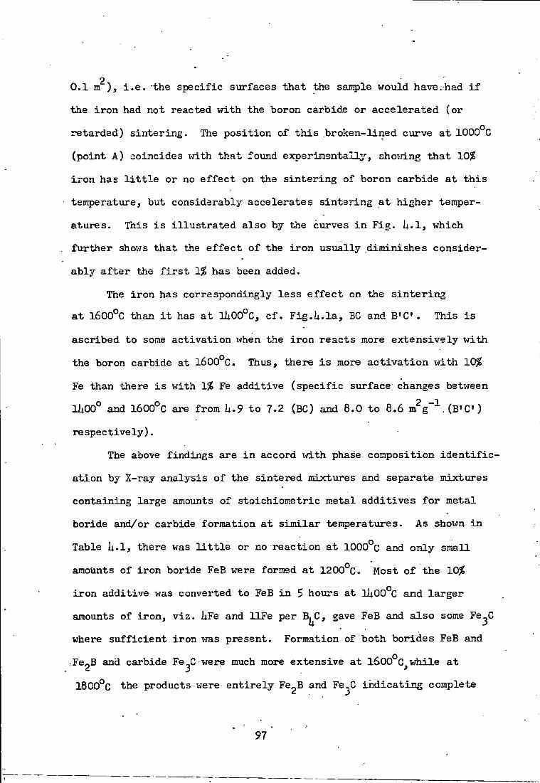
2 0.1 m ) , i . e . the s p e c i f i c surfaces that the sample would have;had i f the i r o n had not reacted with the boron carbide or a c c e l e r a t e d (or retarded) s i n t e r i n g - The p o s i t i o n of t h i s broken-lined curve a t 1000°C (point A) coincides with t h a t found experimentally^-, shovrlng that 10% i r o n has l i t t l e or no e f f e c t on the s i n t e r i n g of boron carbide at t h i s temperature, but considerably a c c e l e r a t e s s i n t e r i n g a t higher temperatures. This i s i l l u s t r a t e d a l s o by the curves i n F i g . U - l , which further shows that the e f f e c t of the i r o n u s u a l l y diminishes considerably a f t e r the f i r s t 1% has been added.
The i r o n has correspondingly l e s s e f f e c t on the s i n t e r i n g
a t 1600°C than i t has a t lUOO°C, c f . Fig.U.la, BC and B ' C . This i s
ascribed to some a c t i v a t i o n when the i r o n r e a c t s more e x t e n s i v e l y with
the boron carbide at 1600°C. Thus, there i s more a c t i v a t i o n \n.th 10%
Fe than there i s with 1% Fe additive ( s p e c i f i c surface changes between
11|00° and 1600°C are from h.9 to 7.2 (BC) and 8.0 to 8.6 m g"" . (B»C )
r e s p e c t i v e l y ) .
The above findings are i n accord xid.th phase composition i d e n t i f i c
a t i o n by X-ray a n a l y s i s of the si n t e r e d mixtures and separate mixtures
containing large amounts of stoichiometric metal a d d i t i v e s for metal
boride and/or carbide formation a t s i m i l a r temperatures. As shown i n
Table U.l, there was l i t t l e or no r e a c t i o n a t 1000°C and only small
amounts of i r o n boride FeB were formed a t 1200°C. Most of the 10^
i r o n additive was converted to FeB i n 5 hoiirs at 3ltOO°C and l a r g e r
amounts of i r o n , v i z . UFe and l l F e per B C, gave FeB and a l s o some Fe^C
irtiere s u f f i c i e n t i r o n vms present. Formation of both borides FeB and
iFCgB and carbide Fe^C were much more extensive a t 1600°C^vjhile a t
1800°C the products were e n t i r e l y Fe^B and Fe^C i n d i c a t i n g complete
97
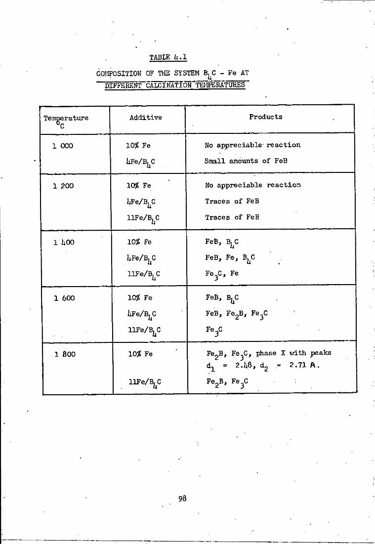
TABLE a . l
COMPOSITION OF THS SYSTEM B^C - Fe AT DIFFEREI^CAI/3INATI0N"'fEMSR^^
Temgerature Additive Products
1 000 10% Fe
UFe/B^C
No appreciable- r e a c t i o n
Small amounts of FeB
1 200 10$ Fe
bFe/B^C
llFe/B^C
No appreciable r e a c t i o n
Traces of FeB
Traces of FeB
1 liOO 10$ Fe
hFe/B^C
llFe/B^C
FeB, B^C
FeB, Fe, B^C
Fe^C, Fe
1 600 10$ Fe
llFe/B^C
FeB, B^C
FeB, Fe2B, Fe^C
Fe^C
1 800 10$ Fe
UFe/Bj^C
Fe^B, Fe^C, phase X vrLth peaks d^ = 2.1i8, d^ = 2.71 A.
Fe^B, Fe^C
98

r e a c t i o n :
B C + l l F e ^ UFe2B + Fe^C
The a c t i v a t i o n opposing the s i n t e r i n g a t 1600*^C, therefore occTirs
when the temperature i s high enough for both boride and carbide form
a t i o n t o be extensive. This causes maxxmiLn changes i n molecular volume
of the c r y s t a l l a t t i c e of reactants and products, leading t o more
extensive s t r a i n and c r y s t a l l i t e s p l i t t i n g , as o f t en encountered i n
s o l i d - s t a t e thermal reactions. The products are more e x t e n s i v e l y
si n t e r e d at higher temperatures (l800°C) , a s s i s t e d p a r t i c u l a r l y by the
comparatively low-melting Fe^B (m.p. 1390°C), c f . F i g . i i . l , CD and
CD'.
h.3.2 Titanium and Zirconium a d d i t i v e s
The s i n t e r i n g of boron carbide i s a c c e l e r a t e d by ti t a n i u m and
zirconium additives at a l l temperatures between 1000° and 1800°C as
shown i n Figs.U,2 and i i . 3 , as found f o r i r o n , the e f f e c t s of the
additives diminish considerably a f t e r the f i r s t 1^ present. The surface
areas with the 10? ad d i t i v e s at 1200°C are s l i g h t l y higher than
expected^ t h i s i s ascribed to a c t i v a t i o n caused t y c r y s t a l l i t e
s p l i t t i n g when a l l of the additive i s completely converted to TiB^ or
ZrB2, compared with only p a r t i a l conversion w i t h i n 5 hours a t 1000°C-
This formation of TiB^ i s analogous to i t s production by the-^reaction:
B^C + 2TiC = 2TiB2 + 3 0 '
also occuring e x t e n s i v e l y a t 1,200°C (Nelson, V/illmore & Womeldorph,
I 9 5 I I ) . There may be some carbon formed i n the r e a c t i o n s :
2Ti + B^C = TiB^ + C and 2Zr + B^C = 2ZrB2 + C,
and released form s o l i d s o l u t i o n i n the boride-carbide matrix,
contributing to the higher surface area. The carbon forms TiC when
la r g e r amounts of titanium and zirconium are present i n s t o i c h i o m e t r i c
r a t i o s of 2Ti/B^C or 3Ti/B|^C, cf. Tables h'2 and l^O-
99 .

1% T i 10% T i
1 OOOOC
10% T i
oron carbide only
Boron carbide + i n e r t additive
si-OOO^C BTgoogc
^•600°c
1 .800^
1 000 1 200 1 liOO 1 600 1 800 Calcination temnerature 9]
1 5 % Titanium additive
1 800°c
1 600 c
r^oo^
1 UUU' c
10
.
H
i s
i I H •-3 M
i

Boron carbide only
1$ Zr 10$ Zr
10$ Zr
1$ Zr
Boron carbide only
1 000 1 200 1 uoo 1 600 rSoo Calcination temperature ^C
000°C 200°C
600^0 800^0
Boron carbide + i n e r t additive
1 800°C
1 600°C 1 iiOO^C
1 200°C OOO C
10
S
i M
N M
o
VA
o
H I % Zirconium additive

TABLE l i . 2
COI€»OSITION OF THE SYSTEM B^C - T i
AT DIFFERENT~CALCIMATION TEl^EElATURES
Temperature A d d i t i v e P r o d u c t
1 000 10^ T i H ^ T i B ^ , B^C-
2TiH2/B|^C T i B ^ , T i e
3TiK2/B^G T i B ^ , T i C
1 200 10^ TiH2 T i B ^ , B^C
2TiH2/B|^C . T i B 2 , T i B j TiC
3TiH2/B^C T i B g , T i B , TiC
1 Uoo 10 T i H ^ T i B ^ , B^C
2TiH2/B^C T i B g , T i C
3TiH2/B^C T i B g , TiG
1 600 10^ T i H ^ T i B ^ , B^C
T i B 2 , T i C
3TiH2/B^C T i B ^ , TiC
. 1 800 . 105? T i H ^ T i B ^ , B^C
T i B g , T i C
3TiE2/B^C T i B g , T i C
102
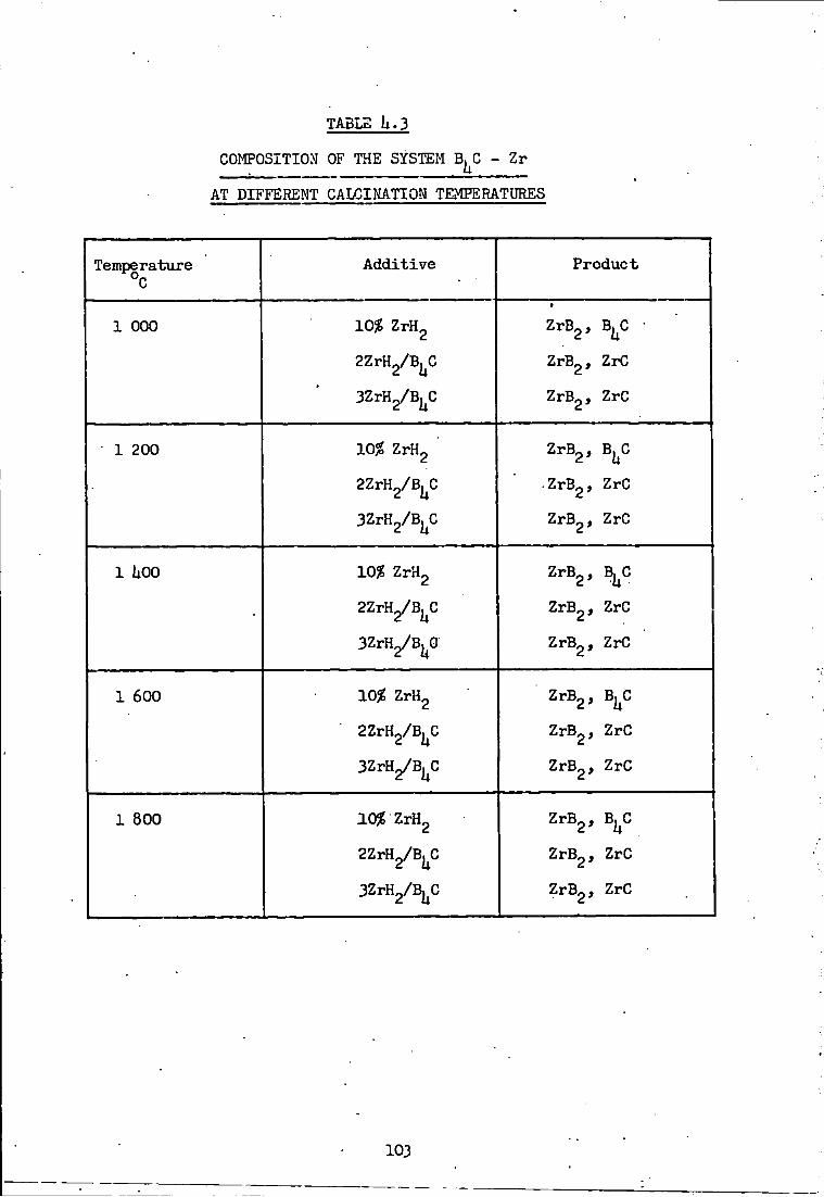
TABLE U.3
COMPOSITIOM OF THE SYSTEM B^C - Z r
AT DIFFERENT CALCINATION TEOTERATURES
Temperature A d d i t i v e P r o d u c t
1 000 10^ ZrH^ •
Z r B ^ , B^C •
aZrH^/B^C Z r B 2 , ZrC
Z r B ^ , ZrC
• 1 200 10% ZrH^ Z r B ^ , B^C
aZrH^/B^C - Z r B g , ZrC
3ZrH2/B^C Z r B ^ , ZrC
1 liOO 1056 ZrH2 Z r B ^ , B^C
• aZrH^/B^C Z r B ^ , ZrC
SZrH^/B^G Z r B g , ZrC
1 600 10^ ZrH2 Z r B 2 , B^C
2ZrH^/B, C 2 h Z r B ^ , ZrC
Z r B 2 , ZrC
1 800 10% ZTH^ Z r B 2 , B^C
Z r B 2 , ZrC
3ZrYi^B^0 Z r B 2 , ZrC
103

T i t a n i u m and z i r c o n i u m a d d i t i v e s are c o r r e s p o n d i n g l y l e s s
e f f e c t i v e than i r o n a d d i t i v e i n p r o m o t i n g s i n t e r i n g o f b o r o n c a r b i d e
m a i n l y because o f the h i g h e r m e l t i n g p o i n t s o f T i B ^ ( 2 9 8 0 ° C ) and
ZrB^ (30U0* C) compared w i t h Fe2B (1390°C) and FeB(l$UO°c).. Hence,
a l t h o u g h t i t a n i u m and z i r c o n i u m b o r i d e s can promote s i n t e r i n g by
sxi r face d i f f i i s i o n above about 900°C ( c o r r e s p o n d i n g t o about J m .p , i n
K ) , t h e y can supplement t h i s by c r y s t a l l a t t i c e d i f f u s i o n o n l y above
about ll;O0*^C (co r r e spond ing t o about § m.p . i n K , i . e . the Tammann
t empera tu re ) (Glasson, 1967). 'Hie c a r b i d e s fo rmed a t t he h i g h e r
t empera tu re s , v i z . above 1600°C, behave s i m i l a r l y ( m .p . T i C 3l50°C,
2rC 3530°C, Fe^C 1650°C), so t h a t t i t a n i u m arid z i r c o n i u m c a r b i d e s can
promote s i n t e r i n g by c r y s t a l l a t t i c e d i f f u s i o n o n l y above about lU50°C
and 1650°C.
U . 3 - 3 Vanadium, n i o b i u m and t a n t a l u m a d d i t i v e s
A l l o f these a d d i t i v e s enhance the s i n t e r i n g o f b o r o n c a r b i d e
t o v a r y i n g e x t e n t s dependent on the- m e l t i n g p o i n t s o f t h e m e t a l b o r i d e s
and ca rb ides formed and the e x t e n t t o w h i c h t he s u r f a c e a c t i v a t i o n
accompanying the me ta l b o r i d e and c a r b i d e f o r m a t i o n o f f s e t s Vae l o s s o f
s u r f a c e caused by s i n t e r i n g , c f . F i g s . U . l i , U.5 and U .6. The vanadium
a d d i t i v e s are the most e f f e c t i v e f o r enhanc ing s i n t e r i n g e s p e c i a l l y a t
lUOO^C. Up t o t h i s t empera tx i re , t he vanadium shows a g r e a t e r t endency
t o f o r m b o r i d e s VB2 (and V^B^^ when more vanadium i s p r e s e n t ) t h a n t o
f o r m i t s ca rb ide VC, c f . Table i i . U - A t h i g h e r t e m p e r a t u r e s , l a r g e r
amoiints o f ca rb ide are fo rmed v/hich may account f o r s u r f a c e a c t i v a t i o n
a t 1600°C. Niob ium and t a n t a l u m a d d i t i v e s are c o m p a r a t i v e l y l e s s
e f f e c t i v e , b u t t h e i r g e n e r a l behaviouo' w i t h change o f t empe ra tu r e ;
resembles t h a t o f vanadium, c f . shapes o f purves i n F i g . U .$a and c 5
t h e y a l s o t e n d t o f o r m b o r i d e s r a t h e r t h a n c a r b i d e s a t t empera tu re s
lOh
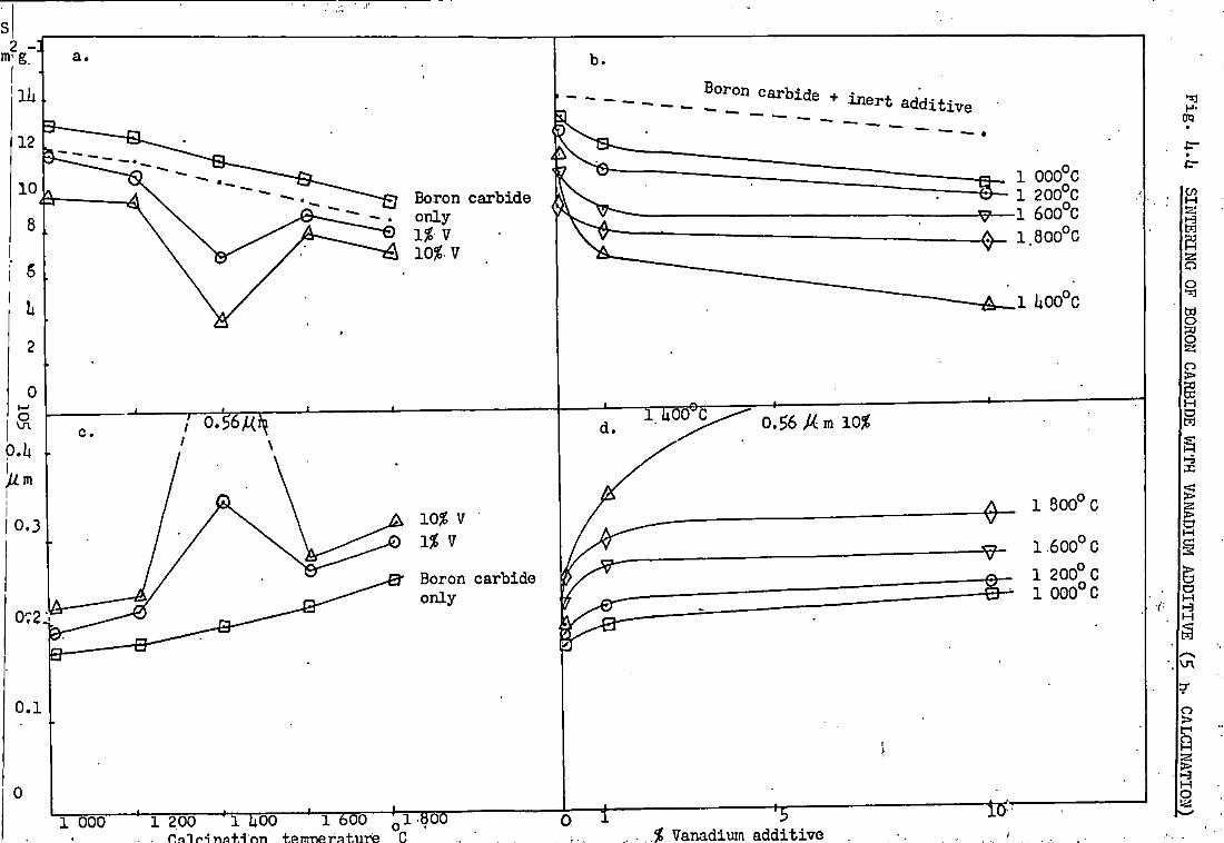
a,
0 . 1
Boron ca rb ide + i n e r t a d d i t i v e
Boron ca rb ide o n l y 1 ^ V 10^. V
' 0.S6M
10% V • 1% V
Boron ca rb ide o n l y
0.56 Am 10^
r"000 ' 1 200 ' l UOO ' 1 600 Q l -tiOO ^— % Vanadium a d d i t i v e
1 000°C 1 200°G
V — 1 600°C 1 800^0
1 U00°C
1 300^ C
1 600*^ c
1 200° C 1 0 0 0 ° 0
10
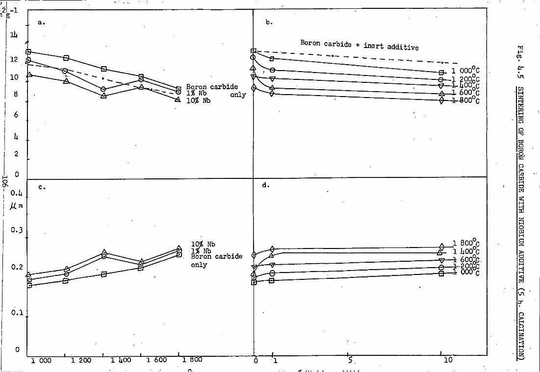
Boron ca rb ide 1 ^ Nb o n l y 10% Nb
b .
Boron ca rb ide + i n e r t a d d i t i v e
1 000°C 1 200oC ^hoolc
A - 1 600°c ^—3r-800°c
10^ Nb
Boron ca rb ide o n l y
A 1 800^c ^ 1 hoo°c V - ^ 600°C.
OOO C
1 000 1 200 m o o 1 600 1 aoo 10

10% Ta
Boron carb ide o n l y
lOOO^C
©"1200^C
i8oo*\;
10^ Ta
1% .Ta
Boron carb ide on ly
1000 1200 iCoo 1600 •*T5oo C a l c i n a t i o n temperature X
^ -s-% Tantalvim a d d i t i v e
8 0 0 ° C
:Li,oo"c 4 6 0 0 ° C
e - 1 2 0 0 " C • innn-°r .
to-
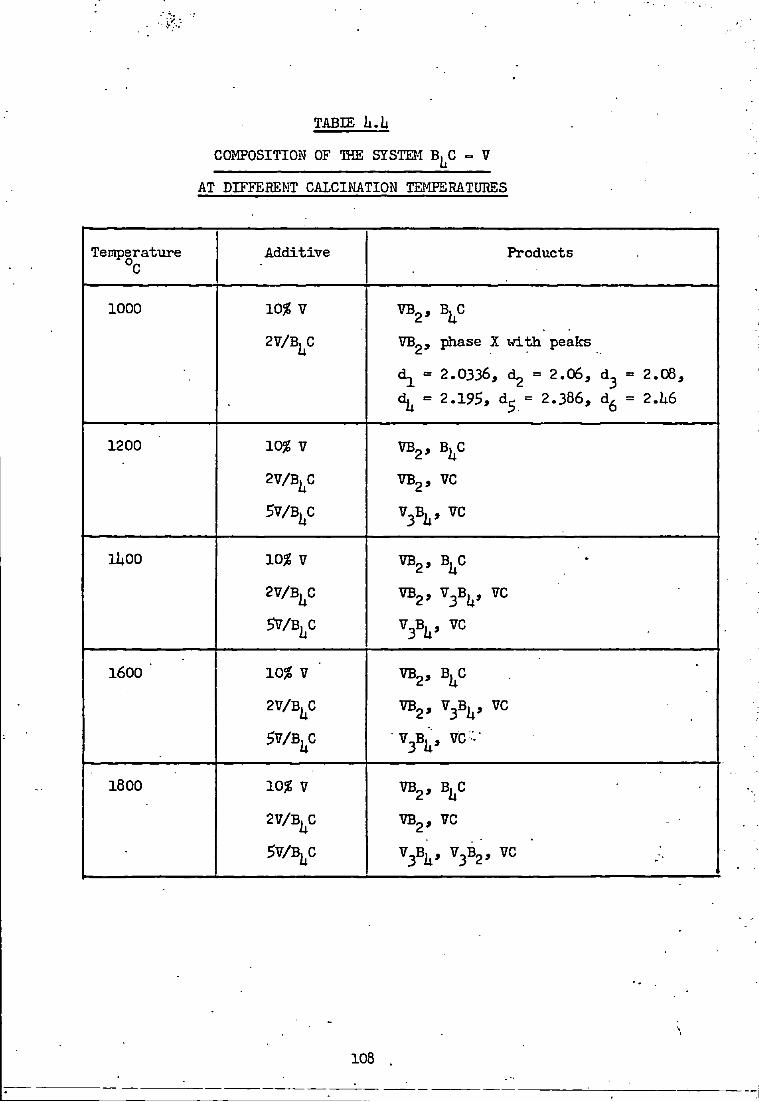
TABIE h.h
COMPOSITION OF IHE STSTEM B^C - V
AT DIFFERENT CALCINATION TEMPERATURES
Temperature °C
A d d i t i v e Products
1000 10? V
2V/B^C
V B ^ , B^C
VB^, phase 2 w i t h peaks
= 2 .0336 , d^ = 2 . 0 6 , d^ = 2 . 0 8 ,
«= 2.195, = 2 . 3 8 6 , d^ = 2M6
1200 10? V
2V/B^C
5V/B^C
VB2, B C
VB2, vc
V ^ B ^ , v c
lliOO 10? V
2V/B^C
5V/B^C
VBg, B^C
V B ^ , V ^ B ^ , VC
V ^ B ^ , VC
1600 ' 10? V
2V/B^C
5V/B^C
VB2, B^C
VBg, V ^ B ^ , VC
V3B^, VC V
1800 10? V
2V/B^C
5V/B^C
V B ^ , B^C
VB2, VC
V ^ B ^ , V3B2, VC
108

below lliOO'^Cj c f . Tables h-S and h-S. The above f i n d i n g s : are i n
accordance w i t h the m e l t i n g p o i n t s o f t he vanadium b o r i d e s , VB^ ,and •
V^B^' (2U00° and 2350°C) and ca rb ide VC (28 lO°C) b e i n g c o r r e s p o n d
i n g l y lower t h a n those o f the n i o b i u m and t a n t a l u m b o r i d e s and
c a r b i d e s , NbB2 ( 3 0 0 0 ° C ) , TaB2 ( 3 1 0 0 ° C ) , NbC (3W0°C), TaC ( 3 8 8 0 ° C ) .
A l s o , t h e f r a c t i o n a l v o l i m e inc reases when the m e t a l s a re c o n v e r t e d t o
these b o r i d e s and ca rb ides are g r e a t e r f o r v a n a d i m t h a n f o r n i o b i u m
and t a n t a l u m : VB2 ( 0 . 7 1 3 ) , NbB2 ( 0 . 5 l 6 ) , TaB2 ( O - i i S l ) , VC ( 0 . 3 1 7 ) .
h'3M Molybdenum and t u n g s t e n a d d i t i v e s
Both m e t a l a d d i t i v e s g e n e r a l l y promote s i n t e r i n g o f b o r o n c a r b i d e ,
the e x t e n t depending on the m e l t i n g p o i n t s o f t he m e t a l b o r i d e s and
ca rb ides f o r m e d and how f a r su r f ace a c t i v a t i o n accompanying the m e t a l
b o r i d e and ca rb ide f o r m a t i o n o f f s e t s l o s s o f s u r f a c e caused by s i n t e r i n g ,
c f . F i g s . i | . 7 and 1^-8. 10^ molybdenum and t u n g s t e n a d d i t i v e s enhance
s i n t e r i n g a t 1 2 0 0 ° C , 1? Mo i s a lmos t as e f f e c t i v e . A t t h i s t e m p e r a t u r e ,
t he a d d i t i v e s f o r m m a i n l y b o r i d e s , M02BJ and ' 2 5 l a r g e r amounts o f
m e t a l , v i z . 2Mo o r 2U p e r B^C o r 8M0 and 8l'J/B^C, g i v e l o w e r b o r i d e s ,
M0B2, 6- MoB, ft' MoB, I f - M02B, V/Bg, S' ™> ^ - ^ 2? ' ' ^^^^ ^
t r a c e o f a lox^er molybdenum ca rb ide M02C and no d e t e c t a b l e tvmgs ten
c a r b i d e s .
I n t h e s i n t e r i n g exper iments the 10% molybdenum a d d i t i v e g i v e s
a p p r e c i a b l e amounts o f M0B2 as w e l l as Ko^B^ a t 1600*^ and 1 8 0 0 ° C ,
which may account f o r t h e a c t i v a t i o n a t 1 6 0 0 ° C . VJi th l a r g e r amounts o f
m e t a l s , t he X - r a y d i f f r a c t i o n t r a c e s show t h a t molybdenimi and t u n g s t e n
o n l y b e g i n t o f o r m ca rb ides t o any a p p r e c i a b l e e x t e n t a t temperatxi res
above 1 6 0 0 ° C , c f . Tables h*l and I1-8; t h i s accounts f o r some s i i r f a c e
a c t i v a t i o n o f t he boron ca rb ide by the t u n g s t e n a d d i t i v e even a t 1800°C
( F i g . *ii .8a)". The m e l t i n g p o i n t s o f t h e b o r i d e s and c a r b i d e s a r e '
109

TABI£ U«g
COMPOSITION OF THE SYSTEM B^C - Nb
AT DIFFERENT CALCINATION TEi4PERATURES
Temperatures A d d i t i v e P roduc t
1000 10^ Nb NbB2,
2Mb/B|^C NbBg, NbC
5Nb/B^C N^B^, NbC
1200 10^ Nb NbBg,
2Nb/B2^C NbB^, NbC
lliOO lOJg Nb NbBg, V 2Nb/B^C NbB2, NbC
1600 10? Nb NbBg, NbC,
2Nb/B^C NbBg, NbC
5Nb/B^C NbB^, NbC
1800 10% Nb NbB2, V 2Nb/B2^C NbB2, NbC
NbB2, NbC
110

TABLE h.6
COMPOSITION OF THE SYSTET^ Ta
AT DIFFERENT CALCINATION TEMPERATURES
Temperature A d d i t i v e P roduc t s
1000 10? Ta TaB2,
2Ta/B^C TaB2, TaC
1200 10? Ta
2Ta/B|^C TaB2, TaC
5Ta/B|^C TaB^, TaB, TaC
lliOO 10? Ta TaBg,
2Ta/B2^C TaC
5Ta/B^C TaS^, TaC
l6pQ 10? Ta T a B j , TaC,
2Ta/B^C TaC
5Ta/B^C T a B j , TaC
1800 10? Ta TaBg,
10? Ta + ^2^3 TaBg, TaC, ^ a n d Y - AI2O3
2Ta/B^C TaBg, TaC
5Ta/B^C TaBg, TaB, TaC
111

l U
0 . 1
b .
Boron carb ide o n l y
1 ^ Mo 10^ Mo
10^ Mo 1^ Mo
Boron ca rb ide o n l y
1000 1200 lEoO 1600 1800 C a l c i n a t i o n , temperature^ OQ % Molybdenum-addit ive.
Jl^OO^C
op i6oo°c
1800°C 1200°C 111 00*^0
^ 1 6 0 0 ^ 0
Q-1000"C
10
TO

1 10« W
2
0
O . l
b .
_ Boron ca rb ide + i j i e r t a d d i t i v e
lOOO^C
lliOO^C 1800°C 1200°C l6Ci0°C
d .
10% W
1% W Boron ca rb ide
o n l y
1000 1200 ' 1600 1800
1800°C 1600°C 1200°C iLiOO^C
1000°C
10
C a l c i n a t i o n temperature 3 C % Tungsten a d d i t i v e

TABLE U>7
COMPOSITION OF 1HE SYSTEM B^C - Mo
AT DIFFERENT CALCINATION TEMPERATURES
Temperature A d d i t i v e P roduc t s
1000 10% Mo
2Mo/B^C
M02B , B^C
MoB, M0B2, ^0^^^
1200 10 Mo
2Mo/B^C
8MO/B|^C
MOgB^, B^C
MoB, /3- MoB
^ - M02B, MoB, Mo^C
ll+OO 10 Mo
2Mo/B^C
Mo2B^, B^C
5 - MoB, M0B2 *
)i~ MOgB, % - MoB, MoC
1600 10% Mo
2Mo/B^C
8Mo/B^C
MoB^, Mo^B^, B^C
MoB, ^ - MoB, M0B2
Mo^B, ^ - MoB, MOgC
1800 10% Mo
•2Mo/B^C;
8Mo/B^C
M0B2, Mo^B^, B^C
MoB, ^ - M6B, -MoBg
J - MoB, phase X w i t h peaks
d^ = 2.6, d^ = 2.U856, d^ = 2.36, d^ = 2 .19i i8, d^ = 1.5, d ^ . = 1.267, d^ = 1.2526

TABLE U.8
COMPOSITION OF THE SYSTEI4 B^C - W
AT DIFFERENT CALCINATION TEI4PERATDRES
Temperature A d d i t i v e P roduc t s
1000 10% W
2W/B^C
1200 10% W W2B5, B^C
2VJ/B^C V - V/gB, (f- vr-B
8VJ/B^C V - v;2B, S- V©, V/
HiOO 10? W W2B5, B^C
2W/B2^C
8W/B^C ^ - W2B, v; .
1600 10? w W2B5; B^C
2W/B2^C cf- VJB, VJ2B^
8W/B^C X - V/2B, W2C, m, w
1800 10? W W2B5, B^C
2V//B|^C S - VJB, W2B^
8lVB^C ^ - W2B, VJ2C, WC
115

g e n e r a l l y lower t h a n those o f the n i o b i u m and t a n t a l u m compounds
and more comparable w i t h those o f t h e vanadium compounds,
v i z , MOgBg 2 1 0 0 ° C , M0B2 2 1 0 0 ° C , S~ MoB 2 3 5 0 ° C , M02C 2laO°C,
MoC 2 7 0 0 ° C , W2BJ 2 3 0 0 ° C , ^ - VJB 2iiOO°C, V- 2770°C , . V7C 2 7 2 0 ° C .
Thus , the b o r i d e s (excep t - W2B) can enhance s i n t e r i n g by b o t h
s u r f a c e and c r y s t a l l a t t i c e d i f f u s i o n over t h e whole t empera tu re range
s t u d i e d ( 1 0 0 0 ° - 1 8 0 0 ° C ) | t h e f o r m a t i o n o f c a r b i d e s i s c o n f i n e d t o
ten5)eratures above about 1200°C f o r c r y s t a l l a t t i c e d i f f u s i o n .
l i - 3 - 5 A lumin ium a d d i t i v e
The e f f e c t o f a lumin ium a d d i t i v e (10?) on the s i n t e r i n g o f bo ron
ca rb ide i n a rgon a t d i f f e r e n t t empera tu res i s shown i n F i g . h . 9 a and c .
For more complete compar i son , the b r o k e n - l i n e d curve i n F i g . l i . 9 a
r ep re sen t s the s p e c i f i c su r f aces i f t h e a l u m i n i u m had n o t r e a c t e d w i t h
the boron c a r b i d e or a c c e l e r a t e d ( o r r e t a r d e d ) s i n t e r i n g . The p o s i t i o n
o f t h i s curve i n d i c a t e s t h a t the a l u m i n i u m has l i t t l e o r no e f f e c t on
the s i n t e r i n g o f t he boron ca rb ide a t 1 0 0 0 ° C , T h i s i s c o n f i r m e d by
s i m i l a r exper iments i n vacuo where -the s p e c i f i c Siirfaces o f t h e b o r o n
c a r b i d e s i n t e r e d f o r 5 hours alone o r v r i t h 1? o r 10? A l a re 1 2 - h , 12 .3
2 - 1
and 1 1 . 1 m g . r e s p e c t i v e l y : I n c r e a s i n g t he amount o f a d d i t i v e has
l i t t l e e f f e c t on the s i n t e r i n g , c f . v a l u e s f o r 1? and 10? A l .
The a lumin ium c o n s i d e r a b l y a c c e l e r a t e s s i n t e r i n g a t 1 ,200°C
( F i g , U-9a a n d c ) , even s m a l l e r amounts ( 1 ? ) b e i n g q u i t e e f f e c t i v e ,
c f . cxrrves i n F i g . l i . 9 b and d . I t has much l e s s e f f e c t on the
s i n t e r i n g a t h i g h e r tempera tures ( l i t00°C and 1600°C) where t h e r e i s
c o n s i d e r a b l e a c t i v a t i o n - A t these t empera tu re s t he a l u m i n i u m combines
w i t h t h e bo ron c a r b i d e i n c o n t r a s t t o t empera tu re s be low l l i00°C vrhere
the v j e t t i n g o f t he boron c a r b i d e s u r f a c e by ihe m o l t e n a l u m i n i u m i s
d i f f i c u l t and i n c o m p l e t e . The c o o l e d samples now c o n t a i n no f r e e
116

2 - 1
1600"C
IDDO®C
111 00 C
1800"C
10% Al 1200-C
1200° C
1800° C
IM Al l A l Boron carbide
only l i i00°C
1000 C
1600"C
TDDC ^ G S " moo 1600 1800 • Calcination temnerature C Aluminium additive
globules of so l id i f i ed aluminium as were foTond i n the samples calcined
at 1000°C and 1200°C. This behaviour i s i n accord vxithCX-ray^^analysis^
no aliuninium borides or carbide being found i n samples calcined at
1000°C and 1200°C even vjhere there i s 2A1 per B C present. However,
there i s l i k e l y to be some sol id solution of A l i n B^C at 1200^0 to
accelerate s intering, and this i s probable at lUOO^C where the Z-ray
traces do not show any crys ta l l ine AlB^, but give somewhat broadened
B^C peaks- "Riese correspond to an average c i y s t a l l i t e s ize of 860 2
compared vjith 2000 S estimated from the surface areas. The ca lculat ion
from surface areas assiimes no part icular c r y s t a l l i t e size dis tr ibut ion
but that from X-ray measurements assumes a Gaussian d is tr ibut ion . The
direction of the discrepancy indicates that much of the material has a
smaller range of c r y s t a l l i t e sizes and/or that the aluminium imposes
a s tra in on the boron c r y s t a l l a t t i c e . The aluminium boride evidently
crys ta l l i s e s and s p l i t s off at higher temperatures, causing fxirther
increases in speci f ic surface as found for the samples calcined at
1600°C, i n which AlB^ has been ident i f i ed by Z-ray ana lys i s , c f . Table
li .9- Some of the carbon formed i n the reaction:
2A1 + B^C - AIB2 + 0
may be released as well from sol id solution i n the boron carbide matrix
(as found i n the oxidation of boron carbide (Chapter 7)) and contribute
to the increase in spec i f ic surface. "Die products are more extensively
sintered at the higher temperature of 1800°G.
hM Electron microscopy data
The products of the reactions described above have been examined
by electron microscopy, and the data are discussed below.
li.U-1 Iron additive
Comparison vri-th the orginal boron carbide (Plate i | . l ) shows that
118

TABLE h.9
COMPOSITION OF THE SYSTM B^C - A l
AT DIFFERENT CALCINATION TEt-IFERATURES
Temperature Additive Products
1000 10? Al A l , Bj C
5A1/3B|^C A l , B^C
2A1/B, C a
A l , B^C
1200 10% A l A l , B^C
5AI/3B^C A l , B^C
2AVB^C A l , B^C
lUOO 10? Al A l , B^C
5AV3B^C A l , B^C
2A1/B^C A l , B^C
1600 10% A l A l , B^C
2AVB^C A l R ^ , A l , Bj^C, phase Z with peaks
1800 10% A l AlB^, A l , B^C
10% A l + 5% stearic ac id
Al,.Bj^C, phase X with peaks
d^ = 2.93, d^ = 2.72, d^ = 2 . 6 5 ,
% = 2.52.
2A1/B^C (AIN), Al^O^, AlB^, B^C
119

Plate U . l
(a)
Or ig ina l boron carbide
Magn i f i ca t ion : 12000 X
Or ig ina l boron carbide
1 pn

at lliOO^C (Plate 1^.2(a)), the aggregates are becoming larger by-
coalescing, ass isted by the iron boride Fe^B near i t s melting point,
while the c r y s t a l l i t e s vri.thin the aggregates are merging \rLth loss of
surface. There are s t i l l sons crys ta l s i-ri.th vjell defined faces remaining
at 1600* C (Plate U*2(b)). Further s inter ing occurs with some rounding
of aggregates at 1800°C (Plate l i . 2 ( c ) ) . When more iron has been present
(hFe/B^C), the more extensive conversion of the boron carbide to the iron
boride, FeB, and carbon, v i z . UFe + B C = UFeB + C , has l e f t the material
i n more disperse form, even at 1800°C (Plate l i .2(d))
Titaniiim and zirconium additives
Comparison vri.th the or ig ina l boron carbide (Plate l i . l ) shows that
sintering has started at IhOO^C (Plate l ; . 3 (a ) ) , but there are s t i l l vn.de
ranges of aggregate s izes at higher temperatures, 1800°C, most of the
smaller aggregates have disappeared as i s indicated by Plate l i . 3 (b ) .
Some rounding of the aggregates has become apparent and extensive
sintering set i n . VJhere a stoichiometric amount of titanium has been
present (2Ti/B|^C), the more extensive conversion of boron carbide to the
titanium boride, TiBg, and carbide or possibly carbon, v i z . 2Ti + B C
2TiB2 + C , has l e f t a mixture of larger crys ta l s and aggregates at
1200°C (Plate U.3(c ) ) . There are also some small par t i c l e s of material
i n the background, possibly "free carbon. There i s a" s i m i l a r i t y i n the
behaviour of the reaction and s inter ing of boron carbide by titanium and
zirconium additives, c f . Plates ii .3 to i^.U. Excessive amounts Of -
zirconium react with boron carbide to give ZrBg and ZrC, v i z . B^C +
3Zr = 22rB2 + ZrC, c f . Table U.3 .
li.U.3 Vanadiiim additive
Much finely-divided material i s s t i l l present at 1200°C (Plate
l i . 5 ( a ) ) , comparable vrLth the or ig ina l boron carbide (Plate U . l ) and also
121

Plate L.2
\ C + 10? Fe sintered at ll OO^C for 5 hr .
Magnification: 12000 X
(b)
B^C + 10? Fe sintered at 1600°C for 5 hr,
122

Plate i | .2
(e)
B^C + liFe reacted at l800°C f o r 5 hr<
Magn i f i c a t i on : 12000 X
B^C + 10^ Fe s in tered at l800 C f o r 5hrs
123

Plate U.3
B^C + 10% TiH^ s intered a t liiOO C f o r 5 h r .
Magn i f i ca t ion : 12000 X
B C + 10^ TiH^ s intered at 1800°G Tor 5 hr

Plate h.3
(c)
h^C + 2Ti reacted a t 1200 C f o r 5 hr
Magn i f i ca t i on : 12000 X
125

Plate I4 .U
B, G + 10% ZrH^ mixture
Magn i f i ca t ion : 12000 X
(b)
In 1^ B, C + 10? ZrH^ s in tered a t 1200 C f o r 5 hr,

Plate h.h
4--•
B^C + 3ZrH2 reacted at 1200 C f o r 5 hr
Magn i f i ca t ion : 12000 I
(d)
B^C + 3Ziii2 reacted at 1600 C f o r 5 hr
127

having a xjide range of aggregate s izes . At ll;00*^C the smaller
aggregates have disappeared (Plate h.5(^)» accompanied by a consider
able loss of surface area and corresponding proportional increase i n
average c r y s t a l l i t e s i ze . Extensive s intering and rounding of large
c r y s t a l and aggregates i s apparent at 1800°C (Plate U . 5 ( c ) ) .
h'hM Niobium and tantalum additives
VJith the niobium additive there i s s t i l l some f i n e l y divided
material present at 1200*^C, c f . Plate U.6(b) . At higher temperatures,
smaller part ic les s tar t to disappear and aggregates increase i n s i z e .
Considerable rounding of aggregates at 1600° and 1800* C- i s observed _
(Plate l i .6(c) and ( d ) ) . This behavioinr i s s imi lar to the s intering of
boron carbide i-dth tantalum (Plates i;.7(a) - ( f ) ) . VJhere more tantalum has beer
present (2Ta/B^C), the conversion of the boron carbide to tantalum
boride, TaB2, and carbon, v i z . 2Ta + B^C = 2TaB2 + C, causes pro
gressive disappearance of f ine ly divided material \n.th extensive s intering
and rounding of aggregates at higher temperatiires (Platesl i .7(c) - * ( f ) )»
h'h'S Molybdenum and tiingsten additives
Comparison of the original boron carbide and that calcined with
1056 metal additives at 1200° , lliOO^ and 1600°C indicates s inter ing
and disappearance of smaller aggregates. This also applies to samples
calcined with larger amoiints of additives i n stoichiometric rat ios
2!- ID/B^C and 2V7/B^C as i n Plates h-Q and
U.U.6 Aluminium additive
The aluminium has d i f f i c u l t y i n vjetting the boron carbide surface,
especial ly at the lower temperatures 1000°C and 1200°C. Hence the
electron micrographs for the 1000°C calcinations s t i l l show x ride ranges
128

Plate h'S
(a)
B^C + 10? V sintered at 1200°C for 5 hr
Magnification: I6OOO X
(b)
B^C + 10% V sintered at lliOO^C for 5 hr
129

Plate h.S
B C + 10$ V s intered a t 1800°C f o r 5 h r .
Magn i f i c a t i on : I6OOO X
130

Plate i i , 6
B^C + 10^ Nb mixtiare
Magn i f i ca t ion : I6OOO X
(b)
Bjj: + 10^ Nb sintered at 1200^0 f o r 5 hr
131

Plate h.6
(c)
B, C + 10? Nb sxntered a t 1600^C f o r 5 hr,
Magni f i ca t ion I6OOO X
B^C + 10% <^i.itered a t ISOO^G f o r 5 hr
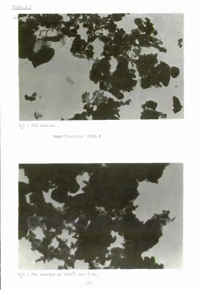
Plate U.7
B| C + 2Ta mixture
Magni f i ca t i on : 12000 X
s
i
B^C 2Ta reacted at 1200°C for 5 hr,
133

Pla te U.7
( c )
m B^C + 2Ta r e a c t e d a t ll^OO^C f o r 5 h r .
M a g n i f i c a t i o n : I6OOO X
(d)
B^C + 2Ta r e a c t e d a t I6OO C f o r 5 h r .
13U

Pla te
(e)
'40
Bj C + 10? Ta s i n t e r e d a t I6OO C f o r 5 h r
M a g n i f i c a t i o n : 12000 X
in ti
10? Ta sin-„c:-_a a t l 8 0 0 ^ f o r 5 hr ,
I
135

Pla t e ii .8
(a )
B^C + 2Mo m i x t u r e
M a g n i f i c a t i o n : 12000 X
(b)
B^C + 2Mo r e a c t e d a t 1200 C f o r 5 h r .
136

Pl^te U.8
(c)
\ B^C + 2Mo r e a c t e d a t IhOOO^C f o r 5 h r .
M a g n i f i c a t i o n : 12000 X
(d)
B^C + 2Mo r e a c t e d a t I6OO C f o r 5 h r .
137

Pla te U.8
B^G + 10^ Mo s i n t e r e d a t liiOO C f o r 5 h r ,
M a g n i f i c a t i o n : 12000 X
B^C + 10^ Mo s i n t e r e d a t 1600°C f o r 5 h r ,
138

Plate ii.8
(g)
^ ^ ^ ^ ^
* ^ ^ ^ ^ ^ ^ ^ ^
B^C + 2Mo r e ac t ed a t I80O C f o r 5 h r
M a g n i f i c a t i o n : 12000 X
139

Pla t e i | . 9
(a)
B^C + 10? W s i n t e r e d a t 1200°C f o r 5 h r s .
M a g n i f i c a t i o n : I6OOO X
(b) \ 1
B, C + 10? W s i n t e r e d a t lliOO^C f o r 5 h r

Pla te h.9
B^C + 2W reac ted a t 1600°C f o r 5 h r .
M a g n i f i c a t i o n : 12000 X
B^C + 10^ W s i n t e r e d a t 1600°C f o r 5 h r ,

of aggregate s i z e s comparable w i t h the o r i g i n a l boron carb ide and t h a t
s i n t e r e d vTithout a d d i t i v e s f o r 5 hours a t 1000°C ( P l a t e s U . l O ( a ) - ( d ) ) .
h»S Conclusions
At temperatures above 1000*^C, metal a d d i t i v e s g e n e r a l l y promote
s i n t e r i n g of the boron c a r b i d e . T h e i r e f f e c t i v e n e s s i s occas ional ly-
reduced when there i s some s u r f a c e a c t i v a t i o n caused by the metals
r e a c t i n g with the boron carbide to form metal bor ides and carb ides
of d i f f e r e n t c r y s t a l l a t t i c e type and molecular volume. V/ith the
poss ib l e exception of tungsten a d d i t i v e , s i n t e r i n g of the boron
carbide vjith metals a t 1800°C i s l e a s t a f f e c t e d by any sur face
a c t i v a t i o n a r i s i n g from the formation of metal bor ides and c a r b i d e s .
Most of the bonding i n boron carbide i s apparent ly c o v a l e n t , whereas
bonding i n the metal borides and carbides i s much more m e t a l l i c ( c f .
Chapter 2 ) . The covalency of the boron carbide i n h i b i t s d i f f u s i o n a t
the s i ir face and a t the g r a i n boundaries (d i scussed i n Chapter 2 ) . Thus,
boron carbide p a r t i c l e s only aggregate and adhere e x t e n s i v e l y a t
temperatures above about Q0% of the m.p. i n K , ( ^ 1 9 0 0 ° C ) c o m p a r e d
with about S0% of the m.p. i n K (Tammann temperature) f o r m e t a l s , metal
oxides , metal borides and carbides (Huttig^ I P U I ) , ( G l a s s o n , 1967). The
Tammann temperatures f o r the metal borides and carb ides produced i n t h i s
research are a l l below lliOO*^C and 1 8 0 0 ° C , so t h a t they can promote
s i n t e r i n g of boron carbide by c r y s t a l l a t t i c e d i f f u s i o n a t these
temperatures. Of the metal a d d i t i v e s i n v e s t i g a t e d , i r o n i s by f a r the
most e f f e c t i v e i n promoting s i n t e r i n g of the boron carbide a t l 8 0 0 ° C j
as shox-m by the much greater changes of c r y s t a l l i t e s during c a l c i n a t i o n ,
c f . Table i i . l O . The 5 h o u r - s i n t e r e d sample was much h a r d e r than those
containing the*, other metal a d d i t i v e s , so t h a t the e f f e c t of i r o n
add i t i ve on f u r t h e r s i n t e r i n g and d e n s i f i c a t i o n dur ing h o t - p r e s s i n g vjas
i n v e s t i g a t e d . T h i s i s descr ibed i n the next chapter .
Iii2

Pla te i i . l O
B^C + A l r eac t ed a t 1000°G f o r 5 h r .
M a g r i f i c a t i o n : 12000 X
(b)
B^C + 2A1 reac ted a t 1000°C f o r 5 h r

Plate 1 .10
(c)
B| C + 1? A l s i n t e r e d a t 1000 C f o r 5 h r
Magni f icat ion: 16000 X
B^C + 10?"Al s i n t e r e d a t lOOO^C f o r 5 h r s

CHAPTER 5
EFFECT OF ADDITIVES ON THE HOT PRESSING
OF BORON CARBIDE
5-1 In troduct ion
The boron carbide produced on a s e m i - t e c h n i c a l s c a l e (Glasson &
Jones , 1969; Jones , 1970) was mainly of submicron s i z e and s i n t e r e d
apprec iably when c a l c i n e d a t temperatures bet>reen 1000 - 1 8 0 0 ° C ,
S i n t e r i n g was enhanced by inc i^ased temperature and time of c a l c i n a t i o n
and a l s o a c c e l e r a t e d by a d d i t i o n of chromium a t temperatures above 1 6 0 0 °
and e s p e c i a l l y a t iBOO^C. More extens ive d e n s i f i c a t i o n was achieved by
hot p r e s s i n g , i . e . heat ing under a pressure exceeding the c r i t i c a l s t r e s s
a t temperatiu-es r e l a t i v e l y c lose to the m.p. (Davjhi l , 1952; B r y j a n e t a l ,
1956) . The submicron poviders from the magnesium r e d u c t i o n process proved
more s u i t a b l e tiian the coarser samples g iven by e l e c t r o t h e r m a l carbon
reduc t ion , the l a t t e r requ ired b a l l m i l l i n g (Jones , 1970) to provide
s u i t a b l e g r a i n s ize-composi t ion f o r e f f e c t i v e hot p r e s s i n g . , I n the
present work changes i n phase .composition and d e n s i t y i n r e l a t i o n to
time and temperature of mixtures of B^C and metal powders when hot pressed
have been s t u d i e d . Mechanism of s i n t e r i n g during hot p r e s s i n g i s
d i scussed i n Chapter 2 . C o r r e l a t i o n of hot pre s s ing with p r e s s u r e l e s s
s i n t e r i n g i s d i scussed by Jones , 1970. Some hot p r e s s i n g was done on
ca lc ium hexaboride a l s o .
5.2 Experimental
5 . 2 . 1 M a t e r i a l s
The mater ia l s used i n t h i s work are the same as those used i n
s i n t e r i n g s tudies descr ibed i n Chapter U (Sec t ion U . 2 . 1 ) .
11*5

5-2,2 Procedure
Attempts ^-jere made to hot press irdxtiires of boron carb ide + metal
p o l l e r i islng the laboratory h o t - p r e s s i n g system descr ibed i n s e c t i o n
3 - 7 . 1 . Owing to t e c h n i c a l d i f f i c u l t i e s i n us ing t h i s equipment the
work was c a r r i e d out on the i n d u s t r i a l system a t Chess ington and Torpoint
descr ibed i n s e c t i o n 3*7-2.
7 -2
Samples of CaB^ vrere hot pressed a t a pressure of 3-00 X 10 N m
f o r 20 minutes a t temperatures up to 2100°C (0.95 X in.p. i n K ) . They
vere allovred to coo l before removal from the d i e . The volxme of the
hot-pressed specimens was determined p y c n o m e t r i c a l l y . The phases present
a f t e r hot pres s ing i-rere i d e n t i f i e d by X - r a y d i f f r a c t i o n .
5.3 R e s u l t s
I n the development of h o t - p r e s s i n g equipment, t h y r i s t o r c o n t r o l
of r e s i s t a n c e heat ing was found to be p r e f e r a b l e to the conventiorial sat i ir-
a t i o n r e a c t o r type , s ince the former gave a more p r e c i s e r e g u l a t i o n of the
sample temperature.
The r e s u l t s obtained when boron carbide i s hot pressed xjith v a r i o u s
a d d i t i v e s are given i n Table 5-1- D e n s i f i c a t i o n of the m a t e r i a l i n c r e a s e d
with i n c r e a s i n g temperature and time of hot p r e s s i n g .
I n the hot -press ing of CaB^ alone d e n s i f i c a t i o n d i d not s t a r t u n t i l
a minimum temperature was reached; t h i s could be-regarded as- the y i e l d
point or so f ten ing p o i n t . I t then proceeded s t e a d i l y and reached a
maximum of 91% a t 2100°C and 2 tons i n .
At each temperature and pressure a raaxisium d e n s i t y was achieved
which d i d not increase apprec iab ly with t ime. I f the temperature and
press tce were increased f u r l h e r , an increase i n dens i ty foUoi-jed
immediately. D e n s i t i e s of \jp to 96 - 97^ of the t h e o r e t i c a l value were
lii6

TABLE 5.1
Mixture Temp. V
Pressure . Time min.
Phases Detected
% Theor e t i c a l dens i ty
B^C + 10? A l 1000 i.5ii X 10^ 5 No r e a c t i o n -
II !! 1200 3.75 X lo" 1 P - AIB2 • 80$
n n 12.00 i.51i X 10^ 5 No r e a c t i o n 66%
n n 1200 M 10 It 71%
Tt n lliOO n 5 II 66%
n n lliOO n 20 n 75? n n 1800 n 5 68? , n n 1800 It 20 n 79^
B^C + 10% F e * lliOO n 5 F e e , 2.988 U9? n n 1600 II 5 F e C , FeB 5U?
B^C + 10% Fe* liiOO II 5 FeB 55? n n 1500 n 5 FeB 58?
n n 1700 It 5 Fee, FeB 60?
B C + 10? ZrU^ 1200 It 5 Z r B 2 , ZrC" 58?
•a- 90 mesh i r o n
+ f i n e l y powdered (reduced) i r o n
lii7

ach ieved .
5.U D i s c u s s i o n
I r o n addi t ives enhanced s i n t e r i n g dioring the h o t - p r e s s i n g of boron
carbide;—analogous to t h e i r e f f e c t imder p r e s s n r e l e s s s i n t e r i n g condit ions
a t 1000 - 1 8 0 0 ° C . Nevertheless the d e n s i t i e s achieved hy- hot pres s ing the
boron carbide vrLth i r o n under pressure of up to 1-5U X 10 Nm ( l ton
i n '*^) a t the temperatures used d i d not exceed fcO? of the t h e o r e t i c a l
v a l u e . I t i s expected t h a t to reach near maxinium d e n s i t i e s , temperatures
above 0.8T K v j i l l be r e q u i r e d (x-;here T = m.p. of B^C) (Jones , 1970) . T h i s
i s i n s p i t e of the formation o f loifer—melting i r o n b o r i d e s , and the low
w e t t a b i l i t y of boron carbide by i r o n .
The d e n s i f i c a t i o n of boron carbide by hot p r e s s i n g with alximiniiim
a d d i t i v e i s more e f f e c t i v e a t h igher p r e s s u r e . The combined e f f e c t of
temperature and pressure he lp to overcome the c r i t i c a l s t r e s s e s and non-wett-
a b i l i t y of boron carbide by aluminium (contact angle 118^) ( c f - Sec t ion 2 .7 .7
Pressxire helps a l s o to increase the r e a c t i v i t y between the tvjo substances
a t t h i s temperature. Thus there i s very l i t t l e or no r e a c t i o n during
pressure s i n t e r i n g ( c f . T a b l e - i i . 9 ) . The formation of AIB2 v/ith a f r a c t
i o n a l volume increase o f 0.5397 r e s u l t s i n a h i ^ e r d e n s i t y than the
formation of A1B^2 (^^^c'^^o^ volume change 5.0766, Appendix I V ) .
Zirconium hydride i s a more e f f e c t i v e pressure s i n t e r i n g promoter
a t loi-rer temperature than i r o n , but l e s s e f f e c t i v e than aluminium
(Table 5 . 1 ) . "
II18

CHAPTER 6
THE FORMATION AND MICROSTRUCTURE OF
BORIDE AND CARBIDE COATINGS ON METAL SURFACES
6.1 I n t r o d u c t i o n
The formation of coatings of borides on meta l s , a l l o y s and- s t e e l
s u r f a c e s has been of i n t e r e s t mainly f o r t h e i r wear, a b r a s i o n and corros ion
r e s i s t a n t proper t i e s (Chapter 2 ) . Methods f o r the format ion of such
coatings are mainly : -
(1) D i r e c t surface boroniz ing by boron.
( 2 ) React ion with boron carbide + a U c a l i metal carbonates .
(3 ) Gaseous boroniz ing .
(k) Boronizing by vapour depos i t i on .
I n the present re search the format ion of boride and carb ide coat ings
on the s i ir face of i r o n and t r a n s i t i o n metal (Group IVA - V I A ) f o i l s by
r e a c t i o n wi th boron carbide i s s t u d i e d . . Improvement i n t h e i r sur face
hardness proper t i e s and compound formation was i n v e s t i g a t e d a t a s e r i e s
of temperatures betvjeen 1 0 0 0 ° and 1 8 0 0 ° C . P o s s i b l e changes i n the
r e a c t i v i t y of boron carbide with metals i n sheet and f i n e powder (descr ibed
i n Chapter h) form are compared.
6.2 Experimental
6 .2 .1 M a t e r i a l s
F i n e l y - d i v i d e d boron c a r b i d e , produced by Glasson & J o n e s . ( 1 9 6 9 ) ,
corresponding to an average c r y s t a l l i t e s i z e of 0,106/4. m ( equ iva l en t
s p h e r i c a l diameter) has been used throughout t h i s work. Meta l f o i l s of
very high p u r i t y (Goodfellows Metals L t d . ) were used. The p u r i t y and
th ickness of the irastal f o i l s are shovm i n Table 6 . 1 .
Ili9

Table 6.1
Metal P u r i t y , % Thickness mm
Fe 0.150
T i 99.70 0.125
Zr 99.67 0.125
V 99.91 0.150
Nb , ... 99.92 0.150
Ta 99.96 0.150
Mo 99.95 0.150
W 99.97 0.150
Cr 99.995 0,02
150

6.2.2 Procedure 2 Pieces of metal f o i l s 1 cm i n size were cleaned i n t r i c h l o r o -
propane vapotir t o fr6e them o f any grease or dust, r i n s e d w i t h water and stored i n a r g o n ^ f i l l e d p l a s t i c bags. Stoichiometric weights of boron carbide ( s u f f i c i e n t to convert 75? of metal i n t o boride and carbide, c f . Tables l i . l - h-9) vjere dispersed i n aqueous ammonia. I h i s suspension was transferred t o one side of the metal f o i l t o form a ii n i f o r m coating. They were dri e d i n an oven (110°C) and then heated f o r a f i x e d time, usually 5 h. i n argon a t d i f f e r e n t temperatiires ranging from 1000° - 1800^0. ^ A f t e r X-ray analysis^ the reacted samples were polished and t h e i r micro-hardness values determined (Section 3-8). Selected f o i l s were examined by transmission electron microscopy (Plates 6-1 and 6.6) using a r e p l i c a technique, and also by means of scanning elec t r o n microscopy (Plates 6-2 -6.5).
6.3 Results
Table 6.2 shows the main metal boride and carbide phases formed a t
d i f f e r e n t temperatures along w i t h t h e i r microhardness values. These
values, are variable where the reacted siarfaces of the metal f o i l s consist
of d i f f e r e n t phases i n layers. The e l e c t r o n microgrpahs i n Plate. 6 show
that these coatings are somevrtiat xmeven compared xv^ith the i n i t i a l polished
uncoated metal surfaces, but nevertheless are generally-harder•for
minimising g a l l i n g o f the metal surfaces.
6M Discussion
As demonstrated e a r l i e r (Vinczeandras, 1969; Ducrot & Poulain,
1970; Samsonov e t a l . 1970b,' and Orfishkin, 1971), t h e b o r i d i n g improves
the raicrohardness and other mechanical properties of i r e t a l s . Ttie micro-
hardness values determined i n the present i n v e s t i g a t i o n are expected t o
151

TABLE 6.2 COMPOSITION OF THE SYSTEMS B C - METAL FOILS HEATED AT VARIOUS TEMPERATURES
Products Microhardiiess SEM
System Temperature Coated side Uncoated side _2 kg mm coated side
Reference Plate
B C-Fe 1000 FeB, 0^6.36, 2.91ii) Fe : 1750
9 1200 Fe^C 00.51, 3.11, 2.3U, 1.18) Fe 1635'
1000 TiBg, Tie Ti 2681i
1200 TiBg, Tie Ti 27Uli
lliOO TiBg, Tie, 0^2.86, 2.li8, 2.10,
2.033, 1.86, 1.66, 1.52, 1.31^
Same as coated side
Did not r e t a i n shape
• 1.311)
- Q 1600 . TiBg, Tie ' TiBg, TiC
B^C-Zr 1000 ZrBg, ZrC Zr 281i5
1200 ZrBg, ZrC 0^2.60, 2.U8, 1.91,
l . l i7)
ZrC ( ^2.59, 2.1i7, 1.91, l-hT, 1.36, 1.30)
2995 6.1
lliOO ZrBg, ZrC ( 2.56, 2.36^ 2630
1600 ZrBg, ZrC ZrBg, ZrC Did not re t a i n shape
-

TABLE 6.2 .cont'd
System Temperature
Products Microhardness
-2 • kg mm
Coated side
SEM Reference
Plate System Temperature Coated side Uncoated side
Microhardness -2 •
kg mm Coated side
SEM Reference
Plate
B C-V 1000
1200
lliOO
1600
V^Bg, (^3.2)
)(- VC, V
V^B^, VC,0^3.1i6, 1.7li, 1.53,
1.37)
T- VC 0^2.37, 2.05, 1.602)
V
• if" VC, Vc, V^B^, VB^
V^B^, VC, V 0H.ii28)
2225
2300
2500 6.2
B| C-Nb 1000 NbB 0^2.3li, 1.59) Nb 23liO
1200 NbBg OO.Oli, 2.00, 1.81) NbC OO.Ol, 1.90, 1.78) . 2350
liiOO NbB^, NbC ( ^3.02, 2.53, 2.31, NbC ( 1.57, 1.56, l . l i l ) 2770
2.Hi, 1.77, 1.38 2630
1600 NbBg, NbC 0O.21, 2.15, 2.Hi, NbC (^0.65, 2.58, 2.53, 2.29, 2805 6.3
1.63, 1.60, 1.39, 1.29, 1.27) 2.12, i.a9,1.143,1.38,1.23) 22 5
1800 NbBg, NbC NbC (^H.59, 1.37, 1.28) 2835 • 3hhO

TABLE 6.2 ...cont'd
Products SEM
Reference Plate
System Temperature °C
Coated side Uncoated side • Microhardness ' g mm
Coated side
SEM Reference
Plate
B C-Ta 1000 1200
TaB2 ( ^2.17, 1.65, 1.58) ^-TaB
y-TaB ( ^3.0li, 2.30, 1.35) 2 75 3100
Hi 00 V-TaB TaC . 3288 1600 ^ -TaB, TaBg TaBg, (S-Ta B , TaC, Ta 35ii2 1800 TaBg (^3.U5, 2.38, 1.73, 1.60,
l.liO, r.3ii, 1.30)
TaBg, (S-Ta B , TaC, Ta 3i*65 2576
6.1i
B^C-Cr 1600 CrB2,/-CrB, Ov^^Q^ CrB2,J^-CrB, Cr^^C^ Did not r e t a i n shape
B C-Mo 1000 ^-MoB, MoBg Mo 1805
1200 5-MoB, ^-MoB Mo 2250
HiOO 5-MoB 0^2.69, 2.59, 2.35, 2.15, y-MOgB, MOgC 2385 2.02, 1.89, 1.79)
y-MOgB, MOgC 205ii
1600 (J"-MoB, P> -MoB, MoBg ^(-Mo^B, Mo C • 1680 1730
6.5
1800 tf-MoB, -MoB, MoBg . X-Mo^B, MoC 0^2.6, 2.1i9, 2.36, 2.19, 1.5, 1.27, 1.25)
2130

TABLE 6.2 ...cont»d
Products Microhardness
l<g mm Coated side
• SEM Reference
Plate System Temperature
• °C Coated side Uncoated side Microhardness
l<g mm Coated side
• SEM Reference
Plate
B|C-W 1000 y-W B (^^1.59, 1.58) 2ii85
1200 /3 -WB /3 -WB ("2.76, 2.35) hhQ6 2822
6.6
liiOO S - m , /3-WB, W If -W2B, w li375.
2850
1600 tT-WB, ^ - r a . / 3 - m (^2.36, 2.26) I4500
2910
1800 /5-WB 0^.76, 2 .99 , 2 .25 , 1.86, l . l l i , 1.09, 1.08)
1.90, -iiiB, we 3812 32liO
VA
* Indicates the d spacings i n j? of uni d e n t i f i e d phases. Microhardness values were determined only on the coated
. side of the f o i l s

Plate 6 .1
Zirconiim coated a t 1200°C f o r 5 hr.
Magnification: 12000 X
Zirconiuin coated a t 1200 C for 5 h r .
156

Plate 6.2
Vanadium uncoated
Magnification: 500 X
Vanadium coated a t lUO0°C 157

Plate 6.3
Niobium uncoated
Magnification: 500 X
I r ^ "41
1 Niobium coated at I6OO0C
158

Plate e.h
Tantalum uncoated
Magnification: 500 X
Tantalum coated a t IBOO^ 159

Plate 6.5
Molybdenum coated a t I6OO C
Magnification: 500 X
Molybdenum uncoated
160
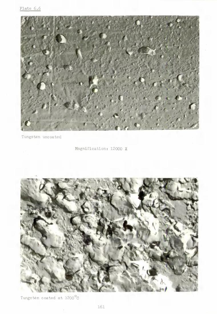
Plate 6.6
Tungsten uncoated
Magnification: 12000 X
Tungsten coated a t 1200°C
161

d i f f e r from those of other workers because of the d i f f e r e n t compositions
of the phases (consisting of borides and carbides) formed on metal
surfaces. The v a r i a t i o n vTill depend on the r e l a t i v e proportions of
borides and carbides and t h e i r s o l i d s o l u t i o n s . The adhesion of the
coatings on t o the metal surfaces v j i l l depend on the volume increases
when the mstals are converted t o borides and carbides (Appendix I V ) and
the x v e t t a b i l i t y of the components of the system.
The reactions with i n d i v i d u a l metal f o i l s are discussed below.
6.U.1 I r o n
The extent of reaction of boron carbide vri-th i r o n f o i l i s high
compared i-rlth t h a t of the powdered metal. The formation of FeB on the
coated side and the absence of products on the uncoated side of the metal
f o i l (Table 6.2) indicates incomplete reaction,^B|^C + liFe = l^FeB + C5
free carbon possibly forms a s o l i d s o l u t i o n . The microhardness of the
coating l i e s xvithin the values c i t e d i n the l i t e r a t u r e ( K a t a g i r i & F u j i i ,
1971).
6-U-2 Titanium and zirconiuin
-Titanium forms r e l a t i v e l y higher proportions of carbide than boride
at 1000° and 1200°C w i t h the reaction becoming f a s t e r at lli00° and 1600°C,
when i t i s completely converted i n t o boride and carbide.
Zirconixim reacts s i m i l a r l y t o t i t a n i u m but tends to form the carbide
at a higher temperature and on the xincoated side of the f o i l . This
indicates the p r e f e r e n t i a l d i f f u s i o n of carbon through the metal and i t s
boride. There i s a s l i g h t s h i f t i n the X-ray d i f f r a c t i o n peaks o f the
products, shoi-ring l a t t i c e s t r a i n i n ZrB2 and ZrC c r y s t a l s . ZrB^ and ZrC
of f i n e p a r t i c l e size 3500 2 and 7hO 2 r e s p e c t i v e l y , are formed on the
xmcoated side a t 1600* C (determined by X-ray l i n e broadening. Section 3.1-3)
162

6.U.3 Vanadium, niobium and tantalum
The carbide i s formed p r e f e r e n t i a l l y on the coated: side of'vanadium
i n contrast to niobium and tantalum, Vanadivim reacts only s l i g h t l y a t
lOOO^C, the r e a c t i o n rate becoming f a s t e r a t higher t e n ^ r a t u r e s .
Niobiiun and tantalum react conqDaratively f a s t e r and form borides i n
preference t o carbides, the l a t t e r increasing i n p r o p o r t i o n at higher
temperatures and on the uncoated side of the f o i l s - Vanadium f o i l forms
a h i ^ e r proportion of carbides compared w i t h the metal pdx-jder ( c f . Tables
k * h and 6.2). I n the case of niobium and tantalum the products are
formed i n s i m i l a r proportions v j i t h the f o i l and pov;der. Tantalum f o i l
forms lox^er borides compared i-rlth those from the f i n e l y powdered metal.
A s l i g h t s h i f t and broadening of the Z-ray d i f f r a c t i o n peaks of r e a c t i o n
products of tantalum f o i l w i t h boron carbide shows c r y s t a l l a t t i c e s t r a i n
and formation of very f i n e c r y s t a l l i t e s i n the range 280 2 - 1050 2,
6 , h M Chromium, molybdenum and tungsten
With molybdenum and tungsten f o i l s the r e a c t i o n products are
s i m i l a r to those formed by the reaction of boron carbide w i t h metal
povjders (Tables h ' l , i i . 8 and 6.2). Carbides are formed only a t higher
temperatures and on the uncoated side of f o i l s . Chromium f o i l being
very t h i n does not r e t a i n shape and reacts almost completely a t lOOO C. '
3his r e s u l t contrasts vrith the reaction vrith*metal powder (Glasson &
Jones, 1969b).
6.5 Conclusions
. At temperatures of 1000°C and above boron carbide reacts w i t h the
metal f o i l s selected i n t h i s research vrork. Reaction a t 1000°C i s
comparatively slovj and remains incomplete during 5 h. heating, being
slowest v j i t h vanadium. There i s a general tendency f o r the metals of
163

period IV i n the Periodic Table t o form carbides i n preference to
borides. This decreases progressively f o r periods V and'VI. -' Carbides
are formed, i n most cases, on the uncoated side of the metal f o i l s
(Table 6 . 2 ) , i n d i c a t i n g the p r e f e r e n t i a l d i f f u s i o n of carbon through
the coatings.
The development of c r y s t a l l a t t i c e s t r a i n and the p a r t i c l e size
(equivalent spherical diameter) of the c r y s t a l s i s a f f e c t e d by the
differences i n c r y s t a l l a t t i c e type and molecular volume' o f the borides
and carbides. X-ray l i n e s h i f t i n g and broadening show c r y s t a l l a t t i c e
s t r a i n i n the borides and carbides of zirconium and tantalum and t h e i r
very f i n e c r y s t a l l i t e size {Zr^^ 3500 2; ZrG 7U0 2; TaC 1959 2 and
'Y- TaB 280 2). I n some cases the borides and carbides form separate
d i s t i n c t regions on metal f o i l s and have d i f f e r e n t values o f micro-
hardness numbers (Table 6 . 2 ) . The significance of these r e s u l t s i s
discussed i n Chapter 8 (Section 8-3)*
161

CHAPTER 7 OXIDATIOH OF BORON CARBIDE, METALS AND METAL BORIDES AND CARBIDES
7.1 I n t r o d u c t i o n
Information so f a r available on the o x i d a t i o n o f metal borides
and carbides has been summarised i n Chapter 2, The k i n e t i c s and
oxidation products depend mainly on the i n t r i n s i c r e a c t i v i t y of the
mate r i a l and available surface a t which o x i d a t i o n could occur. Thus,
the chemical r e a c t i v i t y .of borides and carbides are c o n t r o l l e d generally
t o a considerable degree by the extent t o vihich they have been si n t e r e d
during t h e i r formation and any subsequent c a l c i n a t i o n .
The present work extends t h a t o f Jones (1970) on the o x i d a t i o n o f
f i n e l y - d i v i d e d boron carbide, mainly o f submicron c r y s t a l l i t e s i z e , used
f o r s i n t e r i n g and hot-pressing w i t h metal powders i n Chapters h and 5
and f o r prodxacing metal boride and carbide coatings on metal surfaces i n
Chapter 6. I t con^^ares the oxidation behaviour of coarser boron carbidej
mainly above micron c r y s t a l l i t e s i z ^ x-Tith previous work. Further compar
ison i s made i-jith the oxidation of boron suboxide (B^ ^ 0 ) , since i t was
found t h a t below 850°C the o x i d a t i o n o f boron carbide mainly involves
boron oxidation only, v i z .
Bj C + 30^ = ^^2^2 "** ^
The coated metal s\arfaces described i n Chapter 5 may contain nev/ly-
formed metal borides and carbides and also f r e e boron carbide and metal
idiere r e a c t i o n between the l a t t e r m a t e rial has been incomplete a t lovjer
temperatures. Thus, i n assessing the s u s c e p t i b i l i t y t o oxidation and
scaling resistance o f the coatings, i n f o r m a t i o n i s required on the
165
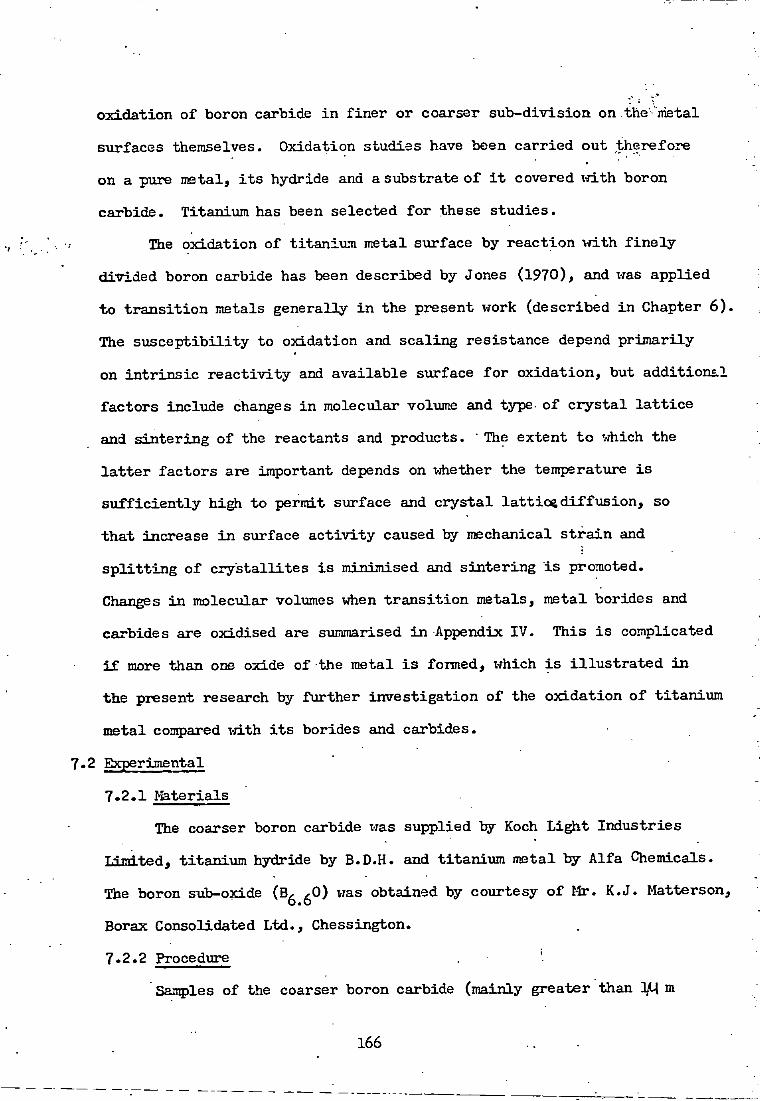
oxidation of boron carbide i n f i n e r or coarser sub-division on the metal
surfaces themselves. Oxidation studies have been c a r r i e d out therefore
on a pure metal, i t s hydride and a substrate o f i t covered v j i t h boron
carbide. Titanium has been selected f o r these studies.
The oxidation of t i t a n i u m metal surface by r e a c t i o n \ j i t h f i n e l y
divided boron carbide has been described by Jones (1970), and was applied
t o t r a n s i t i o n metals generally i n the present v7ork (described i n Chapter 6 ) .
The s u s c e p t i b i l i t y t o oxidation and scaling resistance depend p r i m a r i l y
on i n t r i n s i c r e a c t i v i t y and avai l a b l e surface f o r o x i d a t i o n , but a d d i t i o n a l
f a c t o r s include changes i n molecular volume and type- of c r y s t a l l a t t i c e
and s i n t e r i n g of the reactants and products. • The extent t o ^^hich the
l a t t e r f a c t o r s are important depends on vjhether the temperature i s
s u f f i c i e n t l y high t o permit surface and c r y s t a l l a t t i c e d i f f u s i o n , so
t h a t increase i n sxirface a c t i v i t y caused by mechanical s t r a i n and
s p l i t t i n g of c r y s t a l l i t e s i s minimised and s i n t e r i n g i s promoted.
Changes i n molecular volumes when t r a n s i t i o n metals, metal borides and
carbides are oxidised are summarised i n Appendix IV- This i s complicated
i f more than one oxide of the metal i s fomed, which i s i l l u s t r a t e d i n
the present research by f u r t h e r i n v e s t i g a t i o n of the o x i d a t i o n o f t i t a n i u m
metal compared vrLth i t s borides and carbides.
7.2 Experimental
7.2.1 Materials
The coarser boron carbide was supplied by Koch L i g h t I n d u s t r i e s
landted, t i t a n i u m hydride by B.D.H. and titanixim metal by A l f a Chemicals.
The boron sub-oxide (B^ 0) was obtained by courtesy o f Mr. K.J. Matterson,
Borax Consolidated Ltd., Chessington.
7.2.2 Procedure '
Samples of the coarser boron carbide (mainly greater than 3 1 m
166

c r y s t a l l i t e size) vrere oxidised isothermally" i n a i r on a -thermal balance
(section 3 . i j ) . Phases were detected by X-ray povider d i f f r a c t i o n ,
7.2.3 Results
Oxidation rates f o r the coarse boron carbide were calculated from
weight changes of the samples during c a l c i n a t i o n shox-m i n Figs. 7*1 - 7*2.
Fig« 7*3 shows the ox i d a t i o n rates f o r boron sub-oxide calcined i n
a i r i s o t h e r n a l l y at temperatures beti-jeen 850° and 1050°C,
Table 7*1 shows the products of oxidation of t i t a n i u m f o i l + boron
carbide a t various temperatures. F i g. 7»k shoi-js the r e s u l t s o f the
oxi d a t i o n of t i t a n i u m hydride at 850°C.
7.3 Discussion 7.3.1 Oxidation o f boron carbide
Below 850°C, the products were mainly boric oxide and carbon, ,
according t o the equation B C + 30^ = ^620^ + C, but a t 950 - lOOO^C,
most of the carbon was oxidised t o carbon monoaclde and carbon dioxide.
The right-hand scales of F i g . 7.1 indicate the percentage o x i d a t i o n of
boron carbide on the basis of ( l ) no combustion of carbon; and (2)
coDiplete combustion of carbon. The l i m i t e d amount o f oxidation recorded
a t 620°C approximated t o f i r s t or 2/3-order k i n e t i c s (these orders being
almost indistinguishable from each other f o r the l i m i t e d coverage o f the
i n i t i a l stages of the r e a c t i o n ) . At higher temperatures, the k i n e t i c s
become mainly parabolic as i n d i c a t e d by the l i n e a r i t y of the p l o t s i n
Fig . 7.2 of ra vs. time, >Aiere m = f r a c t i o n a l increase i n vieight. The
parabolic k i n e t i c s a t temperatures beti-reen 720° and lOOO^C are i n
accordance \j±th the mechanism o f d i f f u s i o n through the layers of diboron
t r i o x i d e and any free carbon surrounding the remaining boron carbide. The
energy of a c t i v a t i o n calculated from the rate constants f o r the parabolic
k i n e t i c s a t 720° and 850*fc f o r the lower tecqjerature o x i d a t i o n of the
167

(1) (2)
oo
1000 c
I t r q .
& H-O 3 O cr
3
Time hoiirs Time hoiirs
m = f r a c t i o n a l increase i n weight
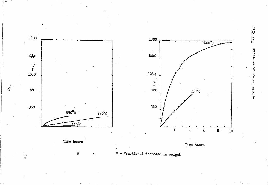
1^
ON
1800
mo
m T
1080
720
360
620'C
1800
lliliO
1080
lOOO C 1- ro
a c+ § b cr
o 3 o
s-
J 1 — I L _ l L
8 . 10
Time hours Time' hours
m - f r a c t i o n a l increase i n weight
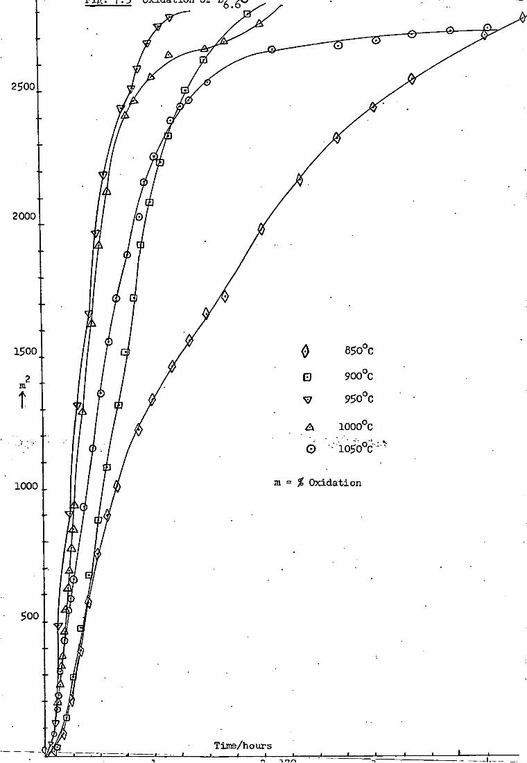
2500
2000
1500
m t
0 •
0
85o°c
900°C
950°C
1000°C
•io5o"c
1000 m = % Oxidation
500
<m~.- Time/hours

TABLE 7-1
OXiamON PRODUCTS OF TITANIUM FOIL, SPONGE, AMD TITANIUl^I HYDRIDE AT VARIOUS TEMPERATURES
Temp. °C
Products• Temp. °C
Products
Titanium f o i l Titanium hydride 360 Ti203 .360 TiO 770 TiO, Ti^Og . 1130 TiO 800 Ti02 ( r u t i l e ) 500 TiO, Ti02 910 Ti02 ( r u t i l e ) 600 TiO, Ti02' 950 Ti02 ( r u t i l e ) 730 TiO, Ti02 ( r u t i l e )
1010 Ti02 ( r u t i l e ) 850 TiO, 7120^, Ti02
930 Ti203* Ti02 ( r u t i l e ) Titanium f o i l + B. C
a 1000 Ti02 ( r u t i l e )
960 Ti02 ( r u t i l e ) 1050 Ti02 ( r u t i l e )
T i tanium ' sponge s 130 TiO, T±20^
hQO TiO, Ti203 500 TiO, Ti203 •
850 TiO, Ti203, TiOg •
•*
171

F i g . 7.'h Oxidation of t i t a n i u m hydride a t 850 C
Hours

coarser boron .carbide i s 2h k c a l inole"^ (5-71* k J mole*"^)- The value
i s s i m i l a r t o t h a t obtained by Jones (1970) f o r the more f i n e l y ;:diyided
sample a t 700°, 750° and 850°C.
At h i ^ e r temperatures, v i z . 950° and 1000°G, the rat e constants
give a value o f 95 k c a l mole""*" (22.73 k J mole^"^) f o r o x i d a t i o n of the
coarser boron carbide sample. The increased a c t i v a t i o n energy a t these
h i ^ e r temperatures corresponds t o extensive combustion o f the carbon
from the boron carbide.
7.3.2 Oxidation of boron sub-oxide
Compared vrith the boron carbide oxidations, the k i n e t i c s of sub
oxide o x i d a t i o n deviate from the parabolic lavr a t e a r l i e r stages
especially a t the higher temperatures, c f . n o n - l i n e a r i t y o f the p l o t s
of m against time (xvhere m = f r a c t i o n oxidised) i n Fig. 7.3. This
indicates t h a t the molten boric oxide, 620^, (m.p. U50°C) from the
boron sub-oxide causes more r a p i d coalescence of the p a r t i c l e s than i n
the boron carbide oxidation. The e f f e c t i v e thickness of product layer
through vjhich the oxygen has t o . d i f f u s e i s more-rapidly increased, thereby
re t a r d i n g the r e a c t i o n , so t h a t the o x i d a t i o n rates of the boron sub
oxide are almost i d e n t i c a l w i t h one anotherat 950°, 1,000° and 1050°C.
The energy of a c t i v a t i o n beti-jeen 850° - 1050°C i s 13 k c a l mole""^ (3.1 k-IT'-
mole"^) F i g . 7.5- Similar r e s u l t s have been obtained f o r boron n i t r i d e
oxidation (Olasson & Jayavreera, 1969; Jayaweera, 1969).
7.3.3 Oxidation of t i t a n i u m , t i t a n i u m hydride and t i t a n i i i m
+ boron carbide
The atmospheric oxidation of t i t a n i u m f o i l , sponge or hydride
produces mainly loi-jer oxides TiO and Ti^O^ a t temperatures below 500°C,
c f . Table 7.1. Progressively l a r g e r amounts of the higher oxide, TiO^j
( r u t i l e ) are formed a t higher temperatvires especially above 850°C when
173

F i g . 7*.5 Arhenius p l o t f o r o x i d a t i o n of B^ 0
1.6 1
1.5.
i . h
1.-3
CU) o
1.2
1.1
1.0 0.5 0.6 0.7 0.8 0.9 1.0
10-
17lt
i t becomes the main product. Oxidation at these higher temperatures i s
enhanced by the transformation of the metal from i t s to - - c r y s t a l • *,
form- ( t r a n s i t i o n point 882°C) and by c r y s t a l l a t t i c e d i f f x i s i o n being
f a c i l i t a t e d above the Tammann temperatures (§ m.p. i n K) o f the metal
(967K, 69li°C)and i t s dioxide, Ti02 (1096K, 823°C). This eases s t r a i n
i n the m aterial caused by differences i n type o f c r y s t a l l a t t i c e and
molecular Trolume betvjeen the metal and i t s oxide products, c f . Appendix IV.
Hox-rever, the oxidation v r i U be i n h i b i t e d u l t i m a t e l y by appreciable
s i n t e r i n g o f the oxide at these temperatures, since t h i s process i s
enhanced also by c r y s t a l l a t t i c e d i f f u s i o n . Accordingly, the k i n e t i c s
are paralinear v i i t h the parabolic law being l i m i t e d t o beti-reen about 5
and 25^ of the oxidation of the f i n e l y - d i v i d e d t i t a n i u m hydride, c f . •
Fig. 7.U. Here, s i n t e r i n g of the oxide product i s more s i g n i f i c a n t i n
t h a t i t causes coalescence of the small p a r t i c l e s of oxide-coated metal
hydride and so more e f f e c t i v e l y increases the thickness o f the oxide layer
through x-jhich d i f f u s i o n has to occur t o maintain the o x i d a t i o n o f the
underlying metal hydride.
The above oxidation• behaviour i s analogous t o tha t o f t i t a n i u m
n i t r i d e described by Glasson and Jayav/eera (1969) and Jayaweera (1969).
The significance of the Tammann temperature i n the s i n t e r i n g and agglo
meration c h a r a c t e r i s t i c of oxide masses during c a l c i n a t i o n processes has
been discussed by Glasson (196?). More r e c e n t l y . Stone (1972) has
emphasised i t s significance f o r the metal i n r e l a t i o n t o i t s oxide during
metal oxidation generally, as a basis f o r r e l a t i n g the o x i d a t i o n
processes t o the periodic c l a s s i f i c a t i o n of elements. There i s some
evidence (Glasson fit Maude, 1971) t h a t vjhere a metal, e.g. N i , has a lovier
Taramanntemperature than i t s oxide, s i n t e r i n g of the oxide i s enhanced.
175

The oxide layer can sinter also by means of surface diffusion vjhich
becomes appreciable above about § itt«p« i n K. Oxidation of titanium
boride, TiBg* and titanium carbide also follow parabolic kinetics at
higher temperatures, analogoiis to titanium metal and nitride and boron
carbide. Recent research on oxidation of zirconi\am boride, ZrB^, alone
(Irving and Worsley, 1%8) or vrlth s i l i c o n carbide or carbon additives
also shai-;s parabolic kinetics (Graham and Tripp, 1970).
Thus, oxidations of the metal coatings containing metal borides,
carbides and unchanged boron carbide vnll follow generally parabolic lavrs.
However, i n i t i a l rates may be modified by secondary factors described
by Gulbransen and Andrews ( I 9 $ l ) for oxidation of metals and by Coles,
Glasson and Jayavjeera (1969) (Jayavieera 1969) for oxidation of ni t r i d e s .
These factors include decreases i n the surface heterogeneity as the
reaction proceeds, changes- i n specific surface or i n l o c a l surface due
to the heat of reaction, s o l u b i l i t y e f f e c t s , impurity concentrations,
possible changes i n oxide composition and e l e c t r i c a l double layer effects.
Ihe reactions are i n i t i a t e d by nucleation at defects on the surf ace • after
which specific amounts of oxide must be formed, to produce coherent layers.
Meam-jhile the reactant surfaces (depending on the s p e c i f i c surface of sample)
remain exposed to the gas phase, so that the rates increase and approach
l i n e a r i t y , cf. the f i r s t S% of the oxidation of titanium hydride (Fig. 7-ii).
When there i s sufficient oxide of rational c r y s t a l l i t e s i z e composition,
i t sinters to form surface films through vihich normal gaseous diffusion
cannot e a s i l y occur. The reactions become controlled by solid-state
diffusion, vrith the kinetics becoming parabolic and l a t e r linear i f
sintering becomes extensive, as i s the case in^the present studies.
176

CHAPTER 8
CONCLUDIMG SIM4ARY This thesis describes the r e s u l t s of i n v e s t i g a t i o n i n t o the
r e a c t i v i t y of boron carbide towards some t r a n s i t i o n metals and t o oxidation. This research forms a p a r t of a isrider study of non-oxide ceramics and r e f r a c t o r i e s ( n i t r i d e s , borides, carbides and s i l i c i d e s ) undertaken a t John Graymore Chemistry Laboratories, Plymouth Polytechnic (Glasson & Jayavjeera, 1969; Jayavjeera, 1969; A l i , 1970; Brockington, Glasson, Jayaweera & Jones, 1973; Brockington, 1973).
The r e a c t i v i t y of boron carbide w i t h metal powders and the
• s i n t e r i n g of the product under normal as w e l l as- high pressure i s
investigated. The boronizing of metal f o i l s w i t h boron carbide w i t h a
view t o improving t h e i r microhardness has been studied. Oxidation of
boron carbide and tit a n i u m up t o 1000°C has been inves t i g a t e d .
8.1 Pressureless s i n t e r i n g of boron carbide w i t h additives
The general e f f e c t of metal a d d i t i v e s , i s t o promote the s i n t e r i n g
of boron carbide a t temperatxires above 1000°C and below i t s melting point.
The changes i n c r y s t a l l i t e size and shape are correlated w i t h temperature
and the amount and nature o f a d d i t i v e . The differences i n the nat-ure of
the bonding of^ the o r i g i n a l material and the products bear an effec't on
the r e s u l t s ; so do the differences i n the molecular vdliame and'-Uattice-
type. I r o n was found to* be * the most e f f e c t i v e s i n t e r i n g agent. The
r e s u l t s are discussed i n r e l a t i o n t o those of e a r l i e r workers.
8.2 Hot pressing of boron carbide w i t h a d d i t i v e s
Similar reactions under hot pressing conditions were studied and
the densities of the products measured. Pressure i s an a d d i t i o n a l f a c t o r
which promotes s i n t e r i n g and d e n s i f i c a t i o n ;
177

The simultaneous a p p l i c a t i o n of pressure and temperatxire i n an
e f f i c i e n t system, where high temperatiires are follovred immediately by
a pressure r i s e , i s the most e f f e c t i v e means of achieving maximum
d e n s i f i c a t i o n (Stringer & VJilliams, 1967).
For most borides and carbides, i n c l u d i n g boron carbide, f i n a l
consolidation of the material i s not achieved u n t i l a temperatiure of
about 0.9 T i s reached (x-jheniT K = m.p.).- This i s explicable i n terms
of t h e i r increased covalency compared x-n.th many oxides and i o n i c n i t r i d e s
i n h i b i t i n g d i f f u s i o n at the surface and a t the g r a i n boundary, c f .
incon^jlete compaction of diamond and borazon (cubic BN) t o a pore-free
state by s i n t e r i n g vri.th or i- j i i ^ o u t pressure. Compaction o f boron carbide
vjithout a d d i t i v e t o almost t h e o r e t i c a l density was achieved only t y hot
pressing t o a temperature above 2300°C (ca 0.95 T) and a t pressures
between 12 - 19 tons i n " (1.8 - 2.8 x 10 Nm~ ) . This procedure i s
l i m i t e d by vjorking pressxire of the graphite mould sets, even though
the powder r a p i d l y consolidates to about 30^ pore density at 1000°C.
The r e s u l t s are i n accordance vrLth the f i n a l d e n s i f i c a t i o n occuring by
a process of p l a s t i c flow when the pressure exceeds the c r i t i c a l stresses
and caiises deformation of asp e r i t i e s a t temperatures r e l a t i v e l y close t o
the melting p o i n t .
8.3 Microstructure o f borides and carbides formed on-metal surfaces
The r e s u l t s obtained on the formation of boride and carbide coatings
on the metal f o i l s shov7 Uiat there i s a considerable v a r i a t i o n i n the nature
and composition of the products depending on the p a r t i c u l a r metal substratt;
nnH the temperattire. The boride phases ranged i n composition from boron-
r i c h t o . metal-rich ones T-d-th metals such as tantalum, molybdenum and
txmgsten, vrhere as the metals t i t a n i u m , zirconium and niobium gave a single
boride phase of the MB composition.
178

Generally, the borides appear t o have been formed by the d i f f u s i o n
of metal atoms i n t o the boron network, w h i l s t iihe reverse mechanism occurs
f o r the production of carbides. This phenomenon, could be explained by
considering the electron a v a i l a b i l i t y of the species involved and
free energies of the formation of iihe product phases.
The increase i n microhardness of the metal irfien subjected t o such
treatment can be explained i n a s i m i l a r vjay and i s i n l i n e w i t h the
IX)stulates of Samsonov et a l (1970a). The coatings obtained adhered
t o the metal substrates. The technique represents a process vrfiereby
machine parts can be *case hardened'. Since such systems are r e a d i l y
prone t o oxidation at elevated temperatures, the exclusion of oxygen
i s e s s e n t i a l unless a protective coating of the product oxide i s maintained,
e.g. Ti02, Zr02.
8.U Oxidation of boron carbide and some metal borides and carbides
^ Factors i n f l u e n c i n g the oxidation o f the metals, metal borides and
carbides and nnreacted boron carbide i n the metal coatings are i n v e s t i g a t e d .
The s u s c e p t i b i l i t y t o oxidation and s c a l i n g resistance depend p r i j n a r i l y on
the i n t r i n s i c r e a c t i v i t y and available surface f o r oxidations, but a d d i t
i o n a l f a c t o r s include changes i n nolecular voliame and the type of c r y s t a l
l a t t i c e and s i n t e r i n g of the reactants and products. The extent t o vjhich
the l a t t e r f a c t o r s are in^iortant depends on i-jhether the temperature i s
s u f f i c i e n t l y high t o permit surface and c r y s t a l l a t t i c e d i f f u s i o n , so t h a t
increase i n surface a c t i v i t y caused by mechanical s t r a i n and s p l i t t i n g of
c r y s t a l l i t e s i s minimised .and s i n t e r i n g i s promoted. Oxidations of the
metals and the components of t h e i r coatings are o f t e n c o n t r o l l e d by
s o l i d - s t a t e d i f f i i s i o n processes, g i v i n g parabolic k i n e t i c s which u l t i m a t e l y
become l i n e a r i f the material s i n t e r s exi;ensively. I n i t i a l rates and
179

k i n e t i c s may be modified t y secondary f a c t o r s , which are discussed.
The o x i d a t i o n behaviour of the above materials i s s i m i l a r t o t h a t of
metal n i t r i d e s - The Tammann temperatures o f the reactants and products
are s i g n i f i c a n t i n the s i n t e r i n g and agglomeration o f the oxidised
m a t e r i a l .
8.5 Future developments
Further research would be advantageous on the hot pressing of boron
carbide \n.-th i r o n (and possibly c o b a l t , n i c k e l or chromium) additives a t
temperatures bet^reen about 1900° and 2300°C (80 - 95% o f m.p, boron
carbide i n K), i n i-^ich the composition and d e n s i f i c a t i o n are co r r e l a t e d
. w i t h the mechanical strength and hardness. The e f f e c t of r a t i o n a l g r a i n
size composition of the o r i g i n a l boron carbide on the d e n s i f i c a t i o n , and
ho\j f a r an optimum grain size composition could be obtained by s i n t e r i n g
during production or subsequent m i l l i n g , vxould be o f i n t e r e s t also.
Consolidation o f metal borides by cold pressing followed hy heating
the "green" compact should be studied, using s u i t a b l e additives t o give
"ceimets", c f . e a r l i e r examples of "hard" metals and V/C/Co system
(Schvraxzkopf & K i e f f e r , 1960). Future work should cover the rate o f
formation o f boride coatings on metal substrates, fol l o v j e d i d e a l l y by
the use of microprobe analysis t o i d e n t i f y conqiosition and phase over
small regions. The e l e c t r i c a l properties of these f i l m s deserve some
a t t e n t i o n f o r an i n d i c a t i o n of the e l e c t r o n i c states o f t^e phases as vrell
as possible i n d u s t r i a l uses. A p p l i c a t i o n of coating by techniques such
as flame and plasma spraying, gaseous and sa l t - b a t h deposition should be
considered. An i n v e s t i g a t i o n of resistance o f the boride and carbide
coatings t o wear and oxidation and t h e i r comparison w i t h the o r i g i n a l
metal f o i l s would be an i n t e r e s t i n g subject f o r f u r t h e r research.
180

R E F E R E N C E S
Alexander, B.M., & B a l u f f i , R.V/.: J.Metals, 1950, 2, 1219-.
AH, 1.2 Ph.D. Thesis (CKAA), 1970.
A l l i e g r o , R.A.: Ceramic Age, 1970, 86(12), 32-3li.
Aravamuthan, V. et a l ; Chem.Age, I n d i a , 1969, 20(U), 281-296.
Aronsson, B.: "Modern Materials" (Ed. H. Hausner), 1960, V O I . H , p-5U ^ £iL-S££" ( '- ^ York: Academic Press). Aronsson, B., Lundstorm, T., & Rundquist, S.: "Borides, S i l i c i d e s and Phosphides", 1965, (London: Methuen).
Artamonov, Ya.A., & Bovkun, G.A.: Tugoplavkie Karbidy, 1970, 217-220 (N.L.L. t r a n s l a t i o n , RTS 7289: June 1972).
Bakarinova, V. I . , S a v i t s k i i , E.M., Arabei, B.C., & Salibekov, S.E.: Izv.Adad.Nauk.SSSR, Neorg.Mater., 1970, 6(11), 2071-2072.
Barnes, E.G., Creel, R.B., fit Torgeson, D.R.: J.Chem.Phys-, 1970, 53(9), 3762-3763.
Biddulph, R.H.: U.S. patent no. 3,505,U38, 1970.
Biddulph, R.H., Matterson, K.J., Brown, A.C.: Private commtinication.
Bliznakov, G., & Peshev, P.: Izv.Old.Khim.Nauki, Bulg.Akad. Nauk., 1970, 2(3), 391-hOO.
Branscomb, T.M., & Hunter, O.Jr.: J.Appl.Phys., 1971, U2(6), 2309-2315-
Brevrer, L., Searcy, A.W., Templeton, D.H., & Dauben, C.H. : J.Am.Ceram. Soc, 1950, 33, 291.
Brockington, B.J., Glasson, D.R., Jayaweera, S.A.A., Jones, J.A. : Joumes d'etude sur l e s n i t r u r e s , Rennes, B r i t t a n y , France 10-11 May 1973.
Brockington, B-J.: Ph.D. Thesis (CMA), 1973.
Brunauer, P.H., Emmett, P.H., & T e l l e r , E, : J.Amer.Chem.Soc., ' 1938, 60, 309.
Brunauer, P.H., Demming, Demming & T e l l e r , E. : J.Am.Chem.Soc., 19iiO, 62, 1723.
Bryjan, E., Missol, W., & B o j a r s k i i , Z., Hutnik, Katowice, 1956, 23, 117.
i
Budnikov, P.P.: "S o l i d State Chemistry**, 1966, p.75, t r a n s l a t e d Shaw, K., 1968 (Lend.: McLaren).
x i

n
Burykina, A.L.. et a l ; Zashch.Pokrytiya Metal^ 1970, No,3, 178-l81i.
Burykina, A.L., & Evtushok, T.M.: Zhatostoikie x Teplostoikie Pokrytiya: Trudy Uth Vses- Soveschch.Po.Zharost.Pokiytiyam, 1968. Leningrad, Nauka, 1969, 89-9li (W.L.L. translation, RTS 7322: July 1972).
Campbell, I.E., Povrell, C.F., WowicfcL, D-H., Sc Gonser, B.VJ,: J.Electro-chem.Soc, 19U9, 96, 318, Carruthers, T.G., & VJheat, T.A.: Proc.Br.Ceram.Soc., 1965, No.5, p.259. Castaing, J-, Danan, J., & Rieux, M.: Solid State Commn., 1972, 10(6), 563-565
C h i o t t i , P.: J.Am.Ceram.Soc, 1952, 35, 123-Clougherty, E.V., Peters, E.T., Kalish, D.: Mater.Process.'s 70»s Nat- SAMPE, 1969, 297-308. Coble, R.L.: J.Am.Ceram.Soc., 1958, 111, 55.
Coble, R.L.t J.Appl.Phys,, 1961, 32, 787, 793. Coble, R.L., & E l l i s , J.S.: J.Am.Cerain.Soc., 1963, hS, U93.
Coble, R.L.: "Fundamental Phenomena i n Material Sciences", 196ii, 1 (New York: Plenum Press). Coble, R.L.: Phys.Sintering, 1969, 1, 3-Cochran, A.A., & Stephenson, J.B.: Met,Trans., 1970, 1(10), 2875-2880.
Cohen, R.L,, Eibshuetz, M., & V/est, K.W.: Phys.-Rev.Le11. , 1970, 21^(8), 383-386. Cueilleron, J,, Lahet, G., & Thevenot, F,, & Paris, R.A.: J.Less-Common Metals, 1971, 21(3), 317-322. Dan'kin, A,A.: Porosh.Met., 1970, 10(10), 81il-8Ui.
Davies, M.W., & Phennah, P.J.: J.Appl.Chem. , 1959, 9, 213.
Dawihl, W.: Z.Metallk., 1952, ii3, 138. . Davydov, V.S-, Ermakov, B.G., Sokolov, V.V.: Tugoplavkie Karbidy, 1970, 20-23 (N.L.L. translation, RTS 7287: Sept. 1972). Deger, M., Riehle, M., & Schatt, V/.: Neue Huette, 1972, 17(6), 3U1-3U8.
Degtev, G.F. et a l : Izvestiya VUZ Mashinostroenic, 1972, (3), 127-131 ,(N.L.L. translation, RTS 79li0: 1972),
De Vynck, I . : Silicates Ind., 1970, 35(12), 308-31U; 1971, 36(1), 1721, 32, (2), U9-5U. Dominey, D.A.: J.Chem.Soc, 1968; A. 712.
x i i

Bucrot, A., & Poulain, J.C.: Ger.Offen. 1,960,973 (Cl. b ) , 25 June 1970, ' . Dut-jez, P., & Odell, F. : J.Electrochem.Soc., 1950, 97, 299-
Easterling, K.E., & Tholen, A.R. : Planseeber Pulvermet,, 1970, 18, 81. Easterling, K.E., & Tholen, A.R.: Z.Metallk., 1970, 6 l ( l 2 ) , 928-931.
Ellingham, H.J.T.: J.Soc.Chem.Ind., 19Ua, 63, 125. Eremenko, V.N., & Naidich, Yu.V.: Zh.Neorgan Khimii, 1959, (9), 2052. Etourneau, J-, Mercuric, J.P., Naslain, R., & Hagenmiiller, P.J.: Solid State Chem., 1970, 2(3), 332-312.
Fedorchenko, I.M., L Skorokh,'V.V.: Porosh.Metall., 1967, No.10(58), 29; "Progress i n Inorganic Materials", 50th Anniversary Publication, Akud.Naiik SSSR, Oct. 1967, p . l . Fisk, Z., Cooper, A.S., Schmidt, P.H., & Castellano, R.N. : Mater. Res.Bull,, 1972, 7(h), 285-288. Fomichev, 0.1., Zhluktanko, E.I., Katkov, V.F., & Spiridonova, I.M.: Zh.Fi2.Khim., 1971, ii5(10), 2688-2689.
Frenkel, J.: J.Phys., 19U5, 9, No.5. Gangler, J.J.: High temp. - High pressure, 1971, 3, U87-502. Geguzin, I.E., & Partskaya, L.N.: Porosh.Metall., 1967, No.l(U9). Georgieva, G.G., Lashko, N.F., & Sorokina, K-P.:. Khiin.Svoistva Metody Anal. Tugoplavkikh Soedin., 1969, 91-97 (N.L.L. translation, RTS 7318: June 1972).
Gert, L-M-, Babadzakhiyapin, A.A., Minashkin, V.I.: Izv.Akad.Nauk. Neorg.Mater,, 1969, 5(12), 219&-99. Gessinger, G.H.: Z.Metallk., 1970, 6 l ( l ) , 53. Gessinger, G.H.: Mod.Davelop.Powder Lfet., 1971, U, 267-279. Gingerich, K.A.: J.Chem.Phys., 1970, 53(2). Glaser, F.V/.: J.Metals, N.Y., 1952, U, 391. Glaser, F.V/., Moskowitz, D., & Post, B.: J.Appl.Phys., 1953, 2U, 731-Glasson, D.R.: J.Chem.Soc, 1956, 1506. Glasson, D.R.: J.Appl.Ghem., 1958, 8, pp. 793-797.
Glasson, D.R.: J.Appl.Chem., Lond. , March, 1961;, l l i , )2 I j \2S'' Glasson, D.R.: J.Appl.Ghem., Lond., 1967, 17, 91.
x x i i

Glasson, D.R., & Jayavjeera, S-A.A.: J.Appl. Chem., Lond., 1968, 18, 65-Glasson, D.R., & Jayavjeera, S.A.A, : J.Appl.Chem., Lond., 1969, 12.9 ^"^^ Glasson, D.R., & Jones, J.A.: J.Appl-Chem., 1969, 19, 125. Glasson, D.R., & Jones, J.A.: J.Appl.Chem., 1969, 19, 37-Glasson, D-R., fit Lindstead-Smith, D.E.D.: 10th Conference on vacuum microbalance techniques, Brunei University, Uxbridge, England, July 1972. Goldschmidt, H.J.: " I n t e r s t i t i a l Alloys", 1967 (London: Buttert-Jorth). Graham, H-C-, & Tripp, W.C: AGARD Conf.Proc, 1970, 52, 9. Graham, H.C.: U.S';Nat.Tech.Inform.Serv., AD, Rep. 1972, No.7li09Ul. Gregg, S.J., & Windsor, G.W.: Analyst, Lond., 19ii5, 70, 336. Gregg, S.J.: J.Chem.Soc, 19li6, 561. Gregg, S.J.: J.Chem.Soc,, 1955, lU38. Gregg, S.J,, & Sing, K.S.VJ.: "Adsorption, Surface Area and Porosity**, Academic Press, London (1967)-Grimshav/, R-W., Heaton, E., & Roberts, A.L.: Trans.Ceram.Soc., 19li5, l a , 76. Groshev, V.I,, Maskayev, A.S., Nezhevenko, L.B., & Plotoratsky, N.I.: Porosh.Met., 1967, No.l(li9), 108. • Gulbransen, E.A., & Andrew, K,F.: J.Electrochem.Soc., 1951, 98, 2iil. Gurin, V.N,, ObuMiov, A.P;, & Korsukova, M.M.: Terent, eva, S.p., Kozlova, I.R-, Planseeber. Pulvermet, 1971, 19(2), 86-90. Hagg, G.: MstallvrLrt., Metalv/iss., Metaltech., 1931, 10, 387. Hagg, G.: Z.Phys.Chem., 1931, (B), 12, 33-Hamijan, H., & Lidman, VJ.: J.Am.Ceram.Soc., 1952, 35, Uli-Hansen, M., & Anderko, K.: "Constitution of Binary Alloys", 1958, p . l l i et seq. (New York: McGraw-Hill). Harvey, M.R.t Diss.Abs., 1965, 25, 6510. Herring, C: J.Appl.Phys., 1950, 21, ii37. Higashi, I . , & Atoda, T.: J.Cryst.Growth, 1970, 7(2), 251-253-Hirsch, P.B., Hoi-rie, A., Nicholson, R.B., Pashley, D.W., & VJhelan, M,J.: "Electron Microscopy of Thin Crystals", 1965 (London: Butten-Jorth) .
xiv

Hosofcaiva, K-, Kogafcubu, K.D.: • Kinzoku hyomen gi j u t s u , 1972, 23(1;) 211-6. Houldsi-rorth, H-S., & Coble, J.W.: Trans.Ceram.Soc., 1922, 22, 111. Huttig, G.F.: Kolloidzeitschrift, 19i;l, 97, 281. Hyde, G.F., et a l ; U.S. Patent No. 3,556,7U7, 1971.
Ir v i n g , R.J., & Vforsley, I.G.: J.Less-Common Metals, 1968, 16(2), 103. James, F.VJ., & Biddulph, R.H.: Private commiinication.
JANAF, Thermochemical Tables, 1960-1971, P.B. 168,370 (New York: Doi-jcheraical Co.). Janes, S-, & Nixdorf, J.: Ber.Ceut-Keram.Ges., 1969, 1^6(2), 60-6U-Jayavjeera, S-A.A. : Ph.D. Thesis (London University) 1969. Johnson, D.L.: Mater,Sci.Res., 1969a, U, 331-3li8. Johnson, D.L.: J.Am.Ceram-Soc, 1969b, |2(10), 562-563. Johnson, D-L.: Phys-of Sintering, 1969c, 1(1-3), ^2r^22'
Johnson, D.L.: J.Am.Ceram.Soc., 1970, 53(10), 57ii-577. Johnson, D.L.: Mod.Develop.Powder Met., 1971, U, 189-198. Jones, F.VK: Proc.Roy.Soc- 166A, 16, 1938-Jones, J.A.: Ph.D. Thesis (CmiAA), 1970.
Karev, V.N., Klyucharev, A.P., Lishenko, L.G., Nazarova, T.S., & Rozen, A.A.: Izv.Adad.Nauk SSSR, Neorg.Mater., 1967, 3(9), I676-I678.
Katagiri, Toshio,gc Fiigii,.K: Kinzoku Hyamen Gijutsu, 1971, 22(5), 238-2145. (N.L.L. translation, RTS 7002: A p r i l 1972). Kaufman, L.: SAMPE Quart., 1970, 2(1), U6-52. Kawashina> C.: Taika, Zairyo, 1970, (112), 16-26. (N.W.L. translation, RTS 7657: Nov. 1972). Kay, D.H.: "Techniques f o r Electron Microscopy", 1965. (Oxford: Blacfctjell). Keihn, F.G., & Keplin, E.J.: J.Am.Ceram.Soc., 1967, 50(2), 81-81;,
Kellam, D., & Micholson, P.S,: J.Am,Ceram.Soc., 1971, 5U(2), 127-128.
"Kemety** (Metal - Ceramics). Izv-vo I L , Moscow, 1962.
XV

Kieffer, R., & Benesovsky, F.: "Hartstof fe" , 1963. (Wien: Springer-Verlag). Kieffer, R., Reister, N., & Fister, D,: Iron Steel Ipst. Lond., 1970, No, 126, 156-161, Kiessling, R,: Acta Chem. Scand., 1950, ii, 209. Kingery, W.D., £c Berg, B.: J .Appl.Phys., 1955, 26, 1205. Kingery, W.D.: "Introduction t o Ceramics", 1960, p.353 (N.Y, Wiley). Kiparisov, S.S,, Nikiforov, O.A., & Kuz'mina, Tu.K.: Izv.Vyssh.Ucheb. Zaved., Tsvet.Met., 1970, 13(5), 93-95 (N.L*L, translation, RTS 7202: May 1972). K i s l i y , P-S,, & Kuzenkova, M.A.: Izv.Akad.Naiik, SSSR, Neorg.Mater., 1966, 2(12), 2139-21iili. K i s l i y , P.S., Kuzenkova, M.A,, & Zaverukha, 0,V,: Phys,Sintering, 1971, 3, 29-U3.
Kosenko, V.A., Rud, B.M. & Sidorova, V.G.: Izv.Akad.Nauk. SSSR, Neorg,Mater,, 1971, 7(8), Ili55-lli56. Kosolapova, T,Ya., & Domasevich, L.T.: Porosh.Met., 1970, 10(5), 1-5. Kosolapova, T-Ya., Makarenko, G.N.: Tugoplavkie Karbidy, 1970, 16-20 (N.L.L. translation, RTS 7315: July 1972), Kosolapova, T,Ya,: Carbides, Properties, Production and Applications, 1971. KostetsfcLi, I . I . , L'vov, S.M. & Kuni t s k i i , Yu,A.: Izv.Akad.Nauk SSSR, Neorg.Mater., 1971, 7(6), 951-955. Kovenskaya, B.A., & Serebryakova, T.I.: Porosh.Met., 1970, 10(5), 79-82. —
Koxvalewski, M,, & Bogkaszewska, K-: Hutnik, 1971, 38(3), 131-137 (N.L.L. translation, RTS 717U: Oct. 1972).
Kuchima, A.Ya., fit Samsonov, G.V.: Neorg.Mater., 1966, No,11, p.1970. Kuczynski, G.C: "Theory, of Solid State Sintering", 1961 (N.Y., Wiley; Interscience). KuentzlBr, R,: Phys,Status S o l i d i , 1970a, l a ( l ) , 291-296. Kuentzler, R,: J.Appl.Phys., 1970b, Ul(3) , 908-909. Kuentzler, R.: J .Phys. (Paris), Collog., 1971, 1(2), CI, 63li-635.
Kugai, L,N., fic Nazaruchuk, T.N-:- Porosh.Met., 1971a, 11(3), 51-55-Kugai, L.N,, & Nazaruchuk, T.N.: Porosh. Met., 1971b, 11(b), 50-53-
x v i .

Kugai, L.N.: Porosh.Met., 1 9 7 1 , 11(12), 5h-57-
K u n i t s k i i , Yu.A., & Marek, E.V.: Porosh.Met., 1 9 7 1 , 1 1 ( 3 ) , 56 - 5 9 .
Kuz'maYu.B., Serebryakova, & Plakhina, A.M.: Zk.Neorg.Khim., 1967, 12(2), 559.
Lenel, F.V., A n s e l l , G.S., & Morris, R . C : Modern Develop.Powder Met., 1971, h, 199.
Len e l , F.V.: Phys.Sintering, 1972, h{l), 120.
L e v i n s k i i , Yu.V., Portnoi, rC.I., & Salibekov, S.E. : (USSR). Vzaimodeistvie Mater. Vysoko-temo. Naznacheniya Sredoi, Sb-Tr.Vses. Nauk.Semin., 1967 (pub.1968), 175-185 (N.L.L. t r a n s l a t i o n , RTS 7U25: Aug. 1972) .
Lindroos, V.K.: Met.Trans., 1 9 7 1 , 2 ( 1 1 ) , 3231-3233.
Lipson, H., & Steeple, H.: I n t e r p r e t a t i o n of X-ray pox^rder d i f f r a c t i o n patterns, 1970, St* Martin's Press, N-Y-
lyakhovich, L.S., Surkov, V.V., Dolmanov, F.V., & Turov, Yu.V.: Metalloved.Term,Obrab.Metal., 1971 , ( 7 ) , 72-73.
MacDonald, N-F., & Ransley, C.E.: Powder M e t a l l . B u l l . , 1959, No.3, p.172.
MacKinnon, I.M., fie V/ickens, A.J,: Chemistry and Industry, 1973, No.16, I8 t h August.
Maire, J . , Slonina, J.P., & Schrer, A.: F r . 1,568,883 <Cl.CppC, Bppf), 30 May 1969-
Manning, C.R., JR., Gurganus, T.B.: J.Am.Ceram.Soc., 1969, 5 2(3), l l 5
Marek, E.V., Kuz'ma, Yu.B., h Kosolapova, T,Ya.: Porosh.Het., 1971, 11(2), 70 -73-
Markovskii, L.Ya., & Bezruk, E.T.: Izv.Akad.Nauk. SSSR, Neorg. Mater. 1967.
Markovskii, L.Ya., Vekshina, N.V., Kondrshev, Yu.D., Voevodskaya, T.K., & Pitirimov, B.Z.: Zh.Prikl.Khira (Leningrad) 1969, i£2(l2), 2690-2695-
Markovskii, L.Ya., Bezruk, E.T., & Berlova, G.E.: Izv.Akad.Nauk. SSSR Neorg.Mater., 1971 , 7 ( 1 ) , 56 - 5 8 .
Maron, F.S., & Germaidze, M.S.: Zh.Prikl.Khim, (Leningrad), 1970, h 3 ( 8 ) , 1826-1827-
Matkovich, V . I . , & Giese, R.F. J r . : Econon^ J - , Z . K r i s t a l l o g r . Kristallgeom., 1965, 122, 116.
Matkovich, V . I . , Giese, R.F. ,Jr., Econon^r, J . , & B a r r e t t , R. : Acta Cr y s t a l -ogr., 1965, 19, 1056.
x v i i

Maude, : M.Phil. Thesis (London), 1970. McDonald, R.J., fit Stuart, W.J.: Acta Crystallogr., 1960, 13, iUi7, Medvedev, O.A., & Sin'kov, V.A.: Porosh.Met., 1971, 11(7), 63-67, Medvedev, O.G., Trunov, L.V., Chernyak, L,V., & Shlyuko, V.Ya.: Poroshkovaya Metallurgiya, 1971, No.3 (99), 101-102. Meerson, G.A., & Gorbunov, A.E.: Izv.Akad.Nauk. SSSR, Neorg,Mater. 1969, 5(12), 2075-2082. Meerson, G.A-, Manelis, R.M-, & Nurmukhamedov, V.: Kh. (USSR). Izv. Akad.Nauk.SSSR, Keorg.Mater,, 1970, 6(7), 1219-1223. Minkevich, A.N., Rastorguev,. L.N., & Yusfina, L , I , : ffetal Science & Heat Treatment, Nos.3-U, March-April, 1967, 191-193. Morgan, C.S.: H i ^ temp. - High pressure, 1971, 3(3), 317-32U, Muchi, I . , & Higuchi, J.: Tetsu To Hagane, 1970, 56(3), 371-381. Mmister, A.: Z .Electrochem., 1959, 63, 807. Murray, P. et a l : Trans.Brit.Ceram.Soc., 195U, 53, hlh* Muta, A., Toda, G-, & Shimanoki, H,: Nippon Kinzokii Gakkaishi, 1968, 32(5), UhO-hh3 (N.L.L. translation, RTS 7197: July 1972). Nabarro, F-R.N.: "The Strength of Solids", Physical Soc, 19li8. Naidich, Yu.V.: Porosh.Met., 196U, (2), 50. Naidich, Yu.V., & Lavrienko, I,V-: Porosh.Met., 1965, (10), 61. Naumenko, V.Ya,: Porosh.Met., 1970, 10(10), 20-22. Nelson, J,A,, VJillmore, T.A., & Womeldorph, R.C.: Refractory Bprides .composed of B fit T i Carbides bonded with Metals. Presented at 99th meeting Electrochem.Soc., VJash, A p r i l 1951. Neshpor, V,S., Friedlender, B.A., fi: Sharupin, B.: N.Inzh.-Fix.Zh,, 1970a, 18(3), 527-530. Neshpor, V.S., Nikit i n a , V.P-, & Rahotnov, V.V.: (USSR). Tugoplavkie Karbidy, 1970b, 132-138 (N.L.L. translation, RTS 6961: Jan. 1972).
Niihara, K.: Bull.Chem.Soc.Jap., 1971, W4.(U), 963-967. Novjotny, H.: MTP.Int.Rev.Sci.Inorg.Chem., Ser.One, 1972a, 10, l5l-l88 Novxotny, H.: Angew.Chem.Internat.Edit. , 1972b, 11(10). Odintsov, V.V., & Paderno, Yu.B.: Izv.Akad.Nauk. SSSR, Neorg-Mater., 1971, 7(2), 333.
X V I X I

O^Neill, P.: M.Sc. Thesis, 1969, Nevrcastle University. Ordan'yan, S.S., et a l : Porosh.Met., 1970, 10(8), 665-668. Oreshfcui, V.D., Svetlopolyanskii, V.I., & Kochkin, P.V. : (USSR) Issled.Naplavcchnykh Splavov Csn.Tugoplavkikh Soedin.-, 1970, 63-72 (N,L.L. translation, RTS 7682: Nov. 1972). Oreshkin, V.D., Svetlopolyanskii, V.I., & Serebryakova, T.I.: Porosh. Met., 1971, 11(3), 78-82. Paderno, Yu.B., Yupko, V.L., Rud, B.M., Kvas, O.F., fic Makarenko, G.N.: Keorg.Mater., 1967, No.2, pp.395, 398. Panasyuk, A-D., Kozina, G.K., Borovikova, M.S., & D'Yakonova, L.V.: (USSR) Fiz.Khim.Poverkh.Yavlenii Vys.Temp., 1971, 185-188 (N.L.L. translation, RTS 7975: Feb. 1973). Pastor, H.: Ind.Ceram., 1969, 6l5, 89-lOU. Pauling, L.: "Nature of the Chemical Bond", 19U0, p.ii20 (Ithaca, N.Y.: Cornell Univ.Press). Pauling, L.: J.Am.Chem.Soc. , 19U7, 69, 5U2. PauUng, L.: Proc.R.Soc.(A), 19ii9, 196, 3h3. Pearson, W.B,: "A Handbook of Lattic Spacings and Structures of Metals and Alloys", 1958, p.7 et seq (Oxford: Bergman). Peisser, H.P., Rooksby, A.J.C, & V^ilson (Ed.): "X-Ray.Diffraction of Polycrystalline Materials", part I , Chapman fic Hall, London, 1960. P i l l i n g , N.B., & Bedx^orth, R.E.: J.Inst.Metals, 1923, 29, 529. Ploog, K., Schmidt, H-, Amberger, E., W i l l , G., & Kossobutzki, K.H. : J.Less-Common Metals, 1972, 29(2), 161-169. Podmore, H.L., & Beasley, E.S.C.: CheiiQr.Ind., 1967, p.llUi3-Portnoi, K.J., £: Romashov, V.M-: Porosh.Met., 1968, 8(2), hl-hh-Post, B.: "Boron, Metallo-Boron Compounds and Boranes" (Ed.R.M.Adams), I96I1, p.301 (New York: Interscience). PoTvell, C.F., Oxley, J.H., & Blocker, J.M.: "Vapour Deposition", 1966, P.3I43 (New York: Wiley). Protasevich, G.F., Novik, F.S., & Voroshnin, L.G.: Vesti AN Bel. USSR ser.fiz.-teldi.Navik, 1972, 1, 20-26 (W.L.L. translation, RTS 7758: Dec.1972). Reijnen, P.: Reactive Solids, Proc.Int.Symp., 6th, 1968 (Pub. 1969), 9 9 - l l l i .
x ix

• Richardson, L . S . , fic Grant, N.J.: Trans. Me t a l l . Soc; A.I'.M.E.,. 1951;, 200. 69. ^ Rj.chardson, F.D., & Jeffes, J.H.E.: J.Iron and Steel, 19li8, 160, 261. Ristic, M.M.: Phys,Sintering, 1969, 1(1-3), A^-^^j^- ' Roeder, E., fic Scholtz, S. : "Special Ceramics", Proc.Syinp.Br.Ceram. Res.Ass., 196h, p.269 (London. Academic Press). Ro'gl, P., Noxjotny, H,, fic Benesovsky, F.: Monatsh.Chem., 1971, 102(3), 678-686. Romashov, V,M., Timofeeva, N.I., Frolova, K.I., fit Romanovich, I.V.: Sov.Pouder Metall.& Jfet.Ceram., 1970, (9), 762-776. Rose, H.E,: Cheiry.Ind., 1967, p.1383. Rundle, R.E.: Acta CiTstallogr., 19li8, 1, 180. Salibekov, S-E,, Lsvinskii, Yu,V,, & Lobankov, V.V.: (USSR), Izv.Akad, Nauk. SSSR, Neorg.Mater., 1970, 6(9), l622-l62li. Samsonov, G.V,, & Golubeva, N,K.: Zh.Fiz.Khim., 1956, 30, 1258. Samsonov, G.V.: Zh.Fiz.Khim., 1956, 30, 2058, Samsonov, G.V., fit Grodshtein, A,E.: Zh.Fix.Khim., 1956, 30, 379. Samsonov, G.V.y fic Umansfciy, Y.S.: "Solid Compounds of Refractory Metals", 1^57, p . l (Moscow: Metallurgizdat). Samsonov, G.V., fit Neshpor, V.S.: Dokl.Akad.Nauk. SSSR., 1958, 122, 1021. Samsonov, G.V.: Usp.Khim., 1959, 28, 189 (U.K.A.E.A. translation, report AERE, Trans. 8^9). Samsonov, G,V-, fie Neshpor, V.S.': "Subjects of PovKier Mettallurgy and Strength of Materials", 1959, Issue 7, p.99 (Kiev: Izdvo Akad.Nauk. SSSR), Samsonov, G.V., Markovskiy, L.Ya., Zhigach, A-F,, & Valyashko, M.G.: "Boron, i t s Compounds and Alloys", 1960, .p.60 (Kiev: Izdvo Akad.Nauk Ukr'. SSR). Samsonov, G.V., Markovskiy, L.Ya., Zhigach, A.F., fit Vlyashko, M.G.: "Bor, Ego Soedineniya i Splavy*', 1960, p.179 (Kiev: Izdvo Akad.Nauk. Ukr. SSR). Samsonov, G.V.: "Refractory Transition Metal Compounds", 1961ia ,(London: Academic Press). Samsonov, G.V.: "High-Melting Compounds of the Rare-Earth Metals", 1961ib, p . l (Moscot-j: Metallurgizdat).
3DC

Samsonov, G.V-: Ukr.Khim.Zh., 1965, 31(10), 1005 (N.L.L- translation, RTS ii233: Dec. 1967); Summarised i n Izv.Akad.Nauk. SSSR, •196'7, 58(10), 76. ~ Samsonov, G.V-: Dokl.Akad.Nauk. SSSR., 1953, 83, 689; Neorg.Mater., 1967, No.l, p.17. Samsonov, G.V., & Neronov, V.A.: Electron Technology, 1970, 3(1-2), 67-72. Sarasonov, G.V., Zhunkovskii, G.L,, & Evtushok, T.M.: Izv.Akad.Nauk, SSSR, Neorg.Mater., 1970a, 6(9), 1617-1621.
Samsonov, G.V., Yurchenko, D.Z., & Bovkun, G.A.: (USSR). Automatic Vfelding, 1970b, 23(10), 70-71. Samsonov, G.V.: (USSR). Tugoplavkie Karbidy, 1970, 9-l5 (N.L.L. translation, RTS 733U: July 1972). Samsonov, G.V., & Kunits'kii, Yu-A.: Dopovidi AN Ufcr. RSR.Ser.A.Fiz. Teldi.Met.Nauki, 1970, 32(11), 10l48-1050. Samsonov, G.V,, Kovenskaya, B.A., Serebryakova, T.I-, & Tel'nikov, E.Ya.: Teplofiz.Vys.Temp., 1971a, 9(1), 195-197. Samsonov, G.V., Koven'ska, B.O., fic Serebryakova, T.I.: Dopovidi - AN Ukr. RSR.Ser.A., 1971b, 33(12), 1127-1129 (N.L.L. translation RTS 7526: Oct. 1972). SavitsfcLi, E.M., Timofeeva, N.I., & Bakarinova, V.I.: Izv.Akad.Nauk. SSSR, Neorg.Mater., 1970a, 6(1), 120-121, SavitsIcLi, E.M., Kul'hakh, A,A., & Evstyukhin, N.A.: (USSR). Tugoplavkie Karbidy, 1970b, 211-21ii. (N.L.L. translation RTS 7288: Sept. 1972). Sav i t s k i i , E.M., & Arabei, B.G.: Izv.Akad.Naiik. SSSR, Neorg.Mater., 1971, 7(U), 617-619), Schick, H.L.: "Thermodynamics of certain Refractory Compounds", 1966, Vols- I and H (Lond. Academic Press).
Scholtz, S.: "Special Ceramics", ProcSyinp.Br.Ceram.Res.Ass., 1962, p.293 (Lond. Academic Press). Schvrarzfcoph, P., & Glaser, F.W,: Third Int.Cong.Electrohead Electro-Chera., Paris, 1953, Paper U. Schviarzkopf, P., & Kieffer, R.: "Refractory Hard tfetals", 1953 (New York: m.ley).
Schwarzkopf, P., & Kieffer, R.: "Cemented Carbides", 1960 (Lond. Macmillan) Serebryakova, T.I., & Sarasonov, G.V-: Zh.Prikl.Khim., 1967, hO(l), 1-6.
xx i

Shaffer, P.T.B., & Samsonov, G.V.: "High Temperature Materials", 196U, Handbooks 1 and 2 (New York: Plenum). Shimohira, T.: Yogyo Kyoki Shi, 1971, 79(908), 132-138. ; Sfcuratovskii, V.N., Dzhemelinskii, V.V., Borisenko, V.A.: Problen^r Prochnosti, 1969, No.6, pp.100-101. Sleptsov, V.M., & Kosolapova, T.Ya.: Sovrem.Probl.Porosh.Met., 1970, 22h-2h2.
SosnOT:skii, L.: Electron Techno., 1970, 3(1-2), 15-19. Srbobran, Rajic: Z.Anal.Chem., 1969, 2U6, 111-115-Stewart, R.W., & Cutler I.B.: J .Am.Ceram.Soc., 1967, 50(U), 176. Stokes, A.R., & V^Llson, A.J.C.: Proc.Phys.Soc., 19hli, 56, 171*. Stokes, A.R.: Proc.Phys.Soc., 19U8, 61, 382
Stone, H.E.N.: Fournal of Materials Science, 1972, 7, Il i i 7 - l l 5 3 -
Storms, E. .: "The Refractory Carbides", Refractory Materials Monogrs. (Ed. J.L. Margrave), 1967, Vol.11 (London Academic Press). Storms, E.K.: MTP (Med.Tech.Publ.Co.) Int.Rev.Sci.Inorg.Chem., Ser. One, 1972, 10, 37-U9-
Stringer, R.K., & V/illiams, L.S.: Fourth Symposium on Special Ceramics", (Stoke-on-Trent) July, 1967. Sugya, T., & Watanabe, 0,: J,Less-Common Metals, 1972, 26(1), 25-31. Takahashi, T,, Sugiyama, K., & Suzuki, Y.: J.Cryst.Growth, 1971, 10(2), 139-lii3. Telegus, V.S., & Kuz«ma, Yu.B.: Porosh.Met., 1968, 8(2), 68-75-ThoiTipson, R., & Wood, A-A-R.: The Chemical Engineer, Feb. 1963-Thonrpson, R. : Lecture Series, R.I.C., 1965, No.5-Thorapson, R. : Process Common W.Mining Met.Conr-, 9th 1969 (Pub.1970a), 563-^71, Edited by Jones, M,J., Inst. I4ining & Met. Thompson, R.: Endeavour, 1970b, 29(106), 3li-38, Boron and i t s Refractory Binary Compounds. Thompson, R.: Progress Boron Chemistry, 1970c, 2, 173-230. Thompson, R. : Chemistry i n B r i t a i n , 1971, 7, No.li, A p r i l . Thornton, P.R.: "Scanning Electron Microscopy^', 1968, Vailmer Brothers Limited, Birkenhead.

Tikkanen, M.H.., & Ylasarri,. S.: Phys. Sintering, 1969, 1", l-lC?
Tikicanen, M.H-, Ylasaari, S., & Blonster, K. : Phys.Sintering, 1971, 3(1), 1-28. Timofeeva, E.N., L Timofeeva, N.J.: (USSR). Zh.Prikl.Khim. (laningrad), 1971, i4ii(6), lli00-ll|02.
Torkar, K., Krischner, H., & Hitsch, E. : Monatsh.Chem., 1971, 102(1), 2h9-255. Toth, L.E.: Transition Metal Carbides and Nitrides,- A p r i l 1971. Troughton, C, & Simms Ltd.: "Photomicrography with the Vickers Projection Microscope" handbook, 1956. Tukamoto, T., Shimada, S., Taguchi, T., Higuchi, J.: Tetsu To Hagane, 1970, 56(6), 661-670.
Tumanov, V,I., Gorbunov, A.E., & Kondratenko, T.M. : Zh.Fiz.Khiia., 1970, l i l i ( 2 ) , 5iiO. Ubbelohde, A.R.: Trans.Faraday Soc, 1931, 28, 28h. Ubbelohde, A.R.: Proc.R.Soc. (A) , 1937, 159, 295. Umanskiy, Y.S.: J.Phys.Chem., VJash., 191*3, 26, 12?.
Varzanov, M.A., Dombrova, I.V., Kalirina, A.A.: U.K. Patent No.l,2li3,569, 1969. Varzanov, M.A., Dombrova, I.V., Kali r i n a , A.A.: B r i t i s h 1,21*3,569, 1971 Vatolin, N.A., Ukhov,.V.F., Eston, O.A., & Dubinin, E.I.: (USSR). Tr. Inst.Met., Sverdlovsk, 1969, 20(2), h2-hS (N.L.L. translation, RTS 7321: Aug. 1972).
•
Vekshina, N.V., & Markovshkii, L.Ya.: (USSR). Khim.Svoistva Metody Anal. Tugoplavkikh Soedin., 1969, 132-l2i2 (N.L.L. translation, RTS 7319: July 1972). Vekshina, N.V., MarkovsfcLi, L.Ya., Kondrashev, Yu.D., & Voevdskaya, T.K.: (USSR). Prikl.Khim. (Leningrad), 1971, 959-963.
Vincze, A.: Banyasz.Kohasz.Lapok.Kohsz., 1969, 102(11), U80-U82. Voroshilov, Yu.V., & Kuz'ma, Yu.B.: Porosh.Met., 1969, 9 ( U ) , 9li-98. Vydrevich, L.A.: Sov,Powder Me t a l l , and Met.Ceram., 1970, (12), 980-985.. Wallbauia, H.J.: Z.Jfetallk., 19Ul, 33, 778. V/ebb, W.W., Norton, J.T., & V/agner, C: J.Electrochem. Soc., 1956, 103, 112.
x x i i i

Werheit, H., Binnenbruck, H,, fit Haiosen, A.-: Phys.Status So l i d i B., 1971, l i 7(l), 153-158. VJheat, T.A., fit Carruthers, T.G.: "Science of Ceramics", 1968, Vol.IV, p.3ii" (Stoke-on-Trent: B r i t i s h Ceram.Soc). VJhite, J.: "Science of Ceramics", Proc.Br.Ceram.Soc., 1962, 1, 305, i b i d . , 1965, 3, 155- ' VJhitteraore, O.J.: Trend Eng.Univ.VJash., 1968, 30(2), 28-33-
Vacks, C.E., fit Block, F.E.: Thermodynamics Properties of 65 Elements -Their Oxides, Halides, Carbides and Nitrides, 1965, U.S. Bureau of Mines Bull. No.605. W i l l , G.: Nature, Lond',, 1966, 212, 175-
van , G.: Electron Technol,, 1970, 3(1-2), 119-126.
Yukin, G.I.: Metalloved. Term Obrab,Metal., 1971, No,8, 662-66U.
Yvon, K,, fit Parthe, E.: Acta Crystallogr,, Sect.B,, 1970, 26(2), 11*9-153-
Zaverukha, O.V.: Porosh,I-iet., 1970, 10(6) , iil - h 3 .
Zelifcman, A.N,, fit Loseva, S.S.: Tsvet Metally, Mosk,, 19li7, 20(U), U l -
Zelikman, A.N., fit Gorovits, N,N,: Zh.Prikl.Khim. SSSR, 1950, 23, 689.
Zworykin, V.K., Morton, G.A., Rambe-rg, E.G., H i l l i e r , J., fit Vance, A.W. "Electron Optics and the Electron Microscope". J. Wiley, N.Y., 19U5.
XXLV

APPENDICES
1. Computer programme for particle size measurement by X-ray method and table of values of particle size.
2. Computer programme fo r calculation of thermodynamic functions and tables of thermodynamic data f o r borides and carbides.
3- Computer programme for graph p l o t t i n g .
U. Computer programme fo r calculation of f r a c t i o n a l volume change for conversion of metals to borides and carbides and t h e i r subsequent conversion to oxides. Fractional volume change tables f o r borides and carbides.
XXV

APPENDIX I
PARTICLE SIZE MEASUREMENT BY X-RAY LINE BROADENING Let bo and BQ be the observed breadths of a s-line and a
m-line respectively, and the doiiblet spearation given by: ^ = 0.285 tan G
G being the angle for maximum d i f f r a c t i o n (Bragg angle). The corrections f o r the oC-doublet to the s-line and the m-line are giyen. by Jones (1938) graphic form, ^^b^ as a function of "^^b^, and ^ B Q as a ftmction of '^BQ, where b and B are the respective breadths a f t e r correction f o r the ^-doublet. In th i s programme, b and B vjere expressed.as an exponential function which vras made to f i t the curve.
These values of b and B were used to calculate the i n t r i n s i c broadening, from the follomng r e l a t i o n between B and^^B:
^B = kp = 2j>
where 2k^ k^ 1
^ ~ ~ — * o" and k i s a parameter of particle size.. 2{l^k^f
This equation was solved by the Nexrton Raphson numerical method to f i n d k values over the desired range of B, i n t h i s case 0 to 1. The k value was back substituted to evaluate/9 , thus giving t the particle size. The particles were assiuned to be i n the form of cube or spheres5 t i s then the cube edge or equivalent spherical, diameter.
The programme calculates particle, sizes.from values of © from 16^ to 2li° i n increments of 0.1*^, and f o r B^ from 0.27° to 0.1;0 i n increment of 0.01^. These ranges for 8 and B^ vjere the ones iisually dealt T^ith i n the application of the programme to .the work described i n th i s thesis. The ranges of Q and as well as t h e i r increment can be changed try
xxvi

s l i g h t modification to the programme. The computer programme i s given below together with a page of
specimen output. Complete tables are available i n a separate folder from Plymouth Polytechnic Library.
XXV11

P A G E A«A»CH4UDHRy» D I M E N S I O N M I U )
30rF0RMAT(* ,0X»lnEASUREM£NT O F PARTICLF S U E B Y T H E X I - R A Y M E T H O D ' I W R I T F . ( 3 . 3 0 )
5rF0fttl/\T| n ! _ » 7 y i ! n 0 ! , 3 X , » 0 . & O » , 3 X » ' 0 . 6 0 » , 3 ) ( » « 0 , 7 0 ' , 3 J ( . » 0 . B 0 ' , 3 X t ' O . 9
• , ' 1 . 6 O S 3 X , ' l , 7 0 * t 3 X # ' U 8 0 M
l** FOlif- iST?//l lXi'TKETA«» \ f M T E ( 3 » U I
. 3 x 3X 4 0 ' f 3 X i f3X
XS«DELTS/BSO
6$«HStRS0 A t i G L E « 1 5 . 9 OO 29 I " 1 . 6 6 I F ( L I \ E ! ; - i 5 l 6 5 t 6 0 i 6 0
60 w 1 ^ l T E ( 3 . ) n H f p R o M ^ l H l I
65 T| lErA « AtlGLE • 0 , 1 lETA
L a i DO 15 e u O ' O
H 2 9 / 1 B 0 . 0 0 . 2 0 5 M S I N ( T H E T M / C O S I T H E T A n
j - ! j O t i e o » i o 01»J
50
45
X f O E L T L / P . L O Y L " E x p i 0 . 1 9 5 - X L I fil.«YL»P.LO
CJO T O 55
C U " e . O » n K » » 3 - 9 . O » R K » « 2 , * 1 . 0 BvZ- ' i .O ' ( 1 . O - R K ' ^ a ) - ( - 2 , 0 A R K I F K D ^ t V » D U - U » D V » / ( V « " 2 I
* ^ f V A K l & ! F » - 0 , C O O l » i » , t , » 1 0 10 P'-'Ifgttg
4 e i p L - t S . Q » R i : B « " 3 - 3 , 0 » R < O » » 2 * U 0 l / ( l » O - R K O * « 2 l ) # t a R T - h T * ? . 0 * 3 . 1 4 3 / 3 6 0 . 0 S ! 2 E - V W E L / ( Q T » C 0 5 ( T H E T A I |
55 J M L I - & I 7 E
2 5 vj.-l h E I 3.20VAtJG L F. 11N t L I . L • 1»14» 20 F O H n A T ( / / * F 6 t 2 f 3 X t l 4 l 7 l
CALL EXJT
FFATURFfi S U P P O R T E D T P * - . M ' J F E 5 T R A C E ^ AfMTi- .NCt lC T R A C E Q/.T l / O R D IHTEGf.pS E.'^TEMOl-O Pl^ECTalON IOCS
^ ? S f 4 ' . ^ ' ^ ' ' ^ ^ ^ E ^ * ^ 5 A & ? S 6 L E 5 106 P R O G R A M
E N D O F C O K P I L A T I O N
/ / X E O
6 0 6

80
THETA
1 6 . 0 0
1 6 . 10
1 6 . 1 9
1 6 . 2 9
1 6 . 3 9
1 6 . ' t ^
1 6 . 5 9
1 6 . 6 9
1 6 . 7 9
1 6 . 8 9
1 6 . 9 9
1 7 . 0 9
1 7 . 1 9
1 7 . 2 9
1 7 . 3 9
0 . 2 7
2 4 1 3
2/ i98
26 ' . 3
2 5 8 9
2 6 3 7
2 6 8 6
2 7 3 7
2791
2B'«6
290't
0
0
0
0
0 . 2 8 C . 2 9 0 . 3 0 0 , 3 X 0 . 3 2 0 . 3 3 0.3<» 0 . 3 5 0 . 3 6 0 . 3 7 0 . 3 8 0 . 3 9 0.<,o
1 7 2 6
1 7 4 8
1 7 7 0
1 7 9 3
1 8 1 6
1 8 3 9
1 8 6 4
1 8 8 9
1 9 1 4
1 9 4 0
1 9 6 7
1 9 9 5
2 0 2 3
2 0 5 3
2 0 8 3
1 3 4 6
1359
1 3 7 3
1 3 B 6
140O
1 4 1 5
1429
1444
1 4 5 9
U 7 4
14i90
1506
1 5 2 3
1539
1 5 5 6
1104
1113
1 1 2 2
1 1 3 2
1141
1151
1 1 6 0
1 1 7 0
H B O
1190
1201
1211
1222
1 2 3 3
1 2 4 4
9 3 7
9 4 4
9 5 0
957
9 6 8
971
9 7 8
9 3 5
9 9 2
999
10O7
l O l H
1022
1029
1037
8 1 4
819
824
6 3 0
dso
8 4 5
831
856
d&2
e.67
0.73
S7f l
884
8 9 0
721
7 2 5
T 2 9
733
737
741
7itS
7x^9
7 5 3
758
- T 6 2
766
771
775
780
6 4 7
6 5 0 *
6 5 3
656
tSg
66 3
(>U
670
6 7 3
677
680
68/f
687
691
6 9 5
587
589
592
595
?9 7
600
6 0 3
606
609
612
6 1 4
617
620 /
6 2 3
6 2 6
537
539
5/,2
5H*t
5^6
5it9
5-51
5'?3
556
5 5 ?
561
563
? 6 S
?6e
570
4 9 5
*l97
*t99
501
5 0 3
5 0 5
507
•509
511
5 2 3
5 1 5
S i C
520
522
524
4 6 0
^ 6 2
^ 6 3
^ 6 5
4 6 7
4 6 8
4 7 0
4 7 2
4 7 4
4 7 6
477
479
4 8 1
4 8 3
4 8 5
429
431
4 3 2
4 3 4
4 3 5
4 3 7
4 3 8
4 4 0
4<,1
4 ^ 3
4 4 5
4 4 6
4<t8
4 4 9
451
4 0 2
4 0 4
4 0 5
A 0 6
4 0 8
A09
411
4 1 2
4 1 3
4 1 5
4 1 6
4 1 7
4 1 9
4 2 0
^ 2 2
w o
H* O H
I/) H-N
ft)
o
w
o B

P A G E 2 A A C H A U D H R Y
D IMENSION - R E A C t O ) . S Y S t S ) . D G T ( 4 0 ) • £ < ( 4 0 ) t W T ( 4 0 ) R r A l ; ( 2 f 9 0 ) M S
9 0 FORmTtU)
9 2 F O R M A T ( / / / / / / • 3 0 X . » W U M 3 E R * t 2 X t • O F • » 2 X S Y S T E M S " 1 2 )
2 fii^Di 2 f 9 5 J ( S Y S ( J ) t J = l » 5 ) 9 D F O P M A T { 5 A 2 )
W R I T E ( 3 . 9 7 ) ( S Y S ( J ) t J » l » 5 ) 9 7 F o n : i i A T { / / , 3 C X » 5 A 2 )
P £ A O i 2 f 9 0 1 N R W R I T E ( 3 . 9 9 ) M P
9 9 F0P . :Va( / / . l O X , ' N U M B E R * • 2 X , ' 0 F « , 2 X » • P O S S I B U E • 1 2 X R E - A C T I O N S - 1 2 I 5 R E A D ) 2 » 1 0 0 ) ( R E A C t J ) 0 = 1 » 8 )
100 F O R L - I A T ( UA't 1 w^ i r £ ( 3 » 1 0 2 ) { R E A C ( J ) . J = l f e »
2 » : 0 5 ) A P I t e p l , C P 1 • D P I »HP1 . G P l . P I M H R E A r ; i 2 , ] C D ) A P 2 , 3 P 2 . C P 2 . [ ) P 2 . H b 2 . G p 2 . P 2 H S R E A 0 ( 2 . 1 O 5 ) A P 3 , f ^ P 3 • C P 3 . O P 3 . H P 3 » G ? 3 . P 3 ^ ^ S
105 F O R H A T ( r l 0 . 2 » F l O , 5 » F l C . & ' , ' , F 1 0 . n ' ^ . • b Sfi ' DHI^S^^" ! !? ' ' ^ '^ !^2*K3 | '1 '^AP3- R l i r A R l - R 2 r i ' ' A K 2 - R 3 C U A R 3
n P2f-PfiP2+^3N'BP3- P l M ' S 2 1 - R 2 K » 8 R 2 - S 3 r \ * 3 R 3 - H ! ? "KISS P2r . ' , 'CP2-^P3M' 'CP3- h y , ' C f e j - R 2 M » C f i ' 2 - R 3 M - C R 3 . . R.
C M S « PJr-MMPi-t- P2r fMP2*P3n* 'MP3- R l M ' H f t i - 9 2 r ! ' ; H ; ? 2 - R 3 M » H k 3 R J ^ ? ' R V ? - 2 2 ^ ^ : ^ ^ - < - 9 0 - ^ " ^ 2 » ' ' » ^ D / 2 - i 2 9 8 . o i * 3 M D C / 3 . 0 * 0 0 / 2 9 8 . 0 OGS^ P1M''GP1+ P 2 M » G p 2 t P 3 M - G P 3 - R l M ' C R i - R 2 / ^ f ; G R 2 - R 3 M * C H 3
DO 120 1=3 . A 2 NT I 1) = 1 0 0 » ( 1 - 2 )
D H V = D M O + O A ^ T +De*'( T * > 2 ) / 2 - 0 + O C M T • ) / 3 . C - 0 D / , T D G U I ) = D H O - T «DA*ALOGt T ) - 0 D ' » ( T . • • 2 ) / 2 . 0 - D C » ( T # » 3 ) /
: 6 . 0 - D O / { 2 , 0 " T J - C O I * T EK( 1 I= E X P l - O G T * ] ) / ( 1 . 9 8 6 * T ) )
1 2 0 W R I T E ( 3 . 1 2 : O M T ( I J »OGTl I ) » E K U 1 lOHT . 1 2 5 F 0 R M A T I 4 X . l A . 0 X i F l 6 f i t 8 X t E 2 5 . 7 i 8 A t F l G . l )
J 1 = J 1 + 1 I F i n P - j n i 3 0 f l 3 0 , 5
130 L - L t - l I F ( M S - l . ) 1 3 5 » 1 3 5 # 2
135 C A L L E X I T
F E A T U R c S SUPPORTED QUE WORD I N T E G E R S I O C S
CORE R E C U l R E M E W T S FOR COMMOri 0 V A R j A b L E S 3 5 2 PROGRAM 9 3 ^
£H0 OF C O M P I L A T I O N '

Temp. K 100 200 300 c o o &00 600 700 800-900
1000 1100 KCIO 130O U O O 1900 1600 1700 i n o o 1900 ZQCO 21Q0 2200 ?300 2^00 2500 2600 2700 ; a o o 2900 3000 3100 3200 3J00 3^00 35O0 36C0 3700 39C0 3900 <t000
RE/^CTION . TIO2•^20-f2C «T IB24>2C0 AG . kcal,
9 7 1 9 U 5 8 9 3 2 & . 7 8 0 ' ) 9 3 . 2 7 2 5 9 1 . 0
5 3 B 7 7 . 2 i . 7 t ; 8 6 . 7 3 9 J 5 0 . 1 31 I 6 9 . ( » 2 3 0 ^ 6 , 2 I t f O g o . S
6 0 7 2 . 6 - 9 7 ^ , 1
- 0 £ t 9 . - 1 6 / 0 3 , 6 - ? * . ' t e o . 1 - 3 2 1 9 9 . 0 - 3 - ; i } i 6 . 3 - ' * 7 / , 6 ' t . 3 - 5 3 0 1 0 . 9 - 6 2 r . 0 O , i .
- 0 ' * 6 2 6 , H -91fi3o.3 - 9 9 0 9 i - t i
- l C 6 2 ( i £ . 0 -.\mh-A - l 2 7 3 / , f l , / - 1 3 ' i 2 7 0 . 9
- i ? ; 7 y j ; 7 . 3 - 1 5 ' » 7 C 1 . J - U 1 3 9 9 . 2 r 1 6 3 0 ^ , 1 , 0 - 1 7 / . 6 2 b . 7
. - i n i 1 5 6 . 5 - 1 0 7 6 3 0 . - 1 9 ' * 0 4 0 . 3
E q . Constant o . o o o d o o o r 00 o . o o o Q o n o E 00
o o o o o o o c 00 o o o o o o o e 0 0 fl20572iE-:e ' f313ri l t -20 1 3 O U 0 7 F - 1 ' . 1 7 3 2 0 3 3 E - 1 O 2 & ( 0 2 0 3 r - O 7 9 l i 6 1 7 j E - C 5 1 0 r i ] 7 ? t K - C 2 5 j 6 ? ' ; i i c - o i i ' * 4 > ^ i 7 e f 01 2'.2flfc0eE
0 c 0 0 0 c 0 0 0 0 0 c 0 . 2 2 1 71 i;3E 0 . 1 leot^iiE . 0 . 2 9 0 i 9 f 4 E C:.103(,7<»^t 0 . 3 ; 2 3 * f c.c'jjfi'.tHr C,'^13 35 7'.F. 0 . 10'J6' f37£ C .2U-0O2 3E C,h02h7b'tB C . V : o t t 5 0 5 E 0 . 1 192SbOE C . l ' ; i 7 S 7 7 £ 0 . i 9 6 2 3 e ' |
0 . 6 3 6 6 3 1 9\: C C V l l p l O E 0 . l2137r.OE 0 . U ) W 3 6 2 E 0 . 2 0 9 3 2 2 5 E 0 . 2&f.0C29c 0 . 3 3 i 6 f c 7 Q E 0 . '»05999CE
02 03 OU CD 05
07 07 00 oa D9 09 C9 cy 10
Is 10 JO l i 11 11 n n
AH k c a l : 0 < ( 2 7 2 . 3 105-79Q.y 1 0 6 1 5 2 . i J
I 0 t 0 2 9 . 9 1 0 G 7 7 5 . 5
j o ' j o J o • 10 ' ! ^JH
10?9V^
1 0 ? f w 1 0 1 5 9 5 - -
I O L 3 76 > 5
9 5 3 2 9 97 52 6-V 6 ^ u 6 . 0 9 5 3 ' ' 9 . 9 9^ 17 8 .B 9 2 9 5 2 . 7 9 1 6 7 1 . B 9C3 3 6 . 2 iy7<*5 17560
3
ft2ajy
7 V / , 5 | . 2 7 7 6 8 6 . 3 7 5 6 6 0 . 0 7 3 9 7 9 . 3 720'«4 . 2
61; 0 1 0 . 9 6 5 9 1 2 . 0 6 3 7 6 0 . ' 1 6 1 5 5 3 . 6
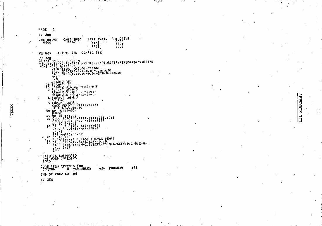
PAGE I
/ / JOB
LOO DRIVE OOOO
CART SPEC 0006 '
CAPT AVAIL O0Q6 • -OOOl-0Q21
PMY D R I V E OOOO 0 0 0 1 0 0 0 2
•ACTUAL 16K CONFIG 16 i ; V2 M09
/ / fQl{
CALL S C F g R ! l i V . O i B . O . - l . O . O . O I
n
6
5
50
•REftDI Z . 3 5 ) ^O^piATi 121
A X . Y N A X f Y M i N 3)
mo r C r s J I f l T O F l RBf\0^ 2 * 5 ) l X ( I ) » 1 * 1 1 ^ 1 )
CflCL* FRLOTI l . x m l Y U I » I F l L - l ^ l / , 5 . 5 0 . 5 0 K';?iuii#^.ooj PAUSE C5 DO 10 l ^ l t ^ ^ l •
20 CALL £CfCR( I ) f Yt n » 0 t ) C^LL FpLOr l - 2 » X ( l l l Y i l l l
20 CALL F P L O r t O . X I 1 I i V c I » ) CALL F |>LOT l l »XA lAX»Yn iA ) L o L * l I P i L - M l ' ^ O t l C O O
ftO 60 TO ZS . Koo F O R M A T ( / / 1 • P L E A S E C / * ^ N G E P E N ' J
30 CALL S C F 0 R l 7 . S C F X , S C F Y i 0 . , d . l
H X
CALL | c E t ? 5 ! x N ! ^ * 2 : r / s c F x ; ; ! i ^ ^ ^ ^ CALL ; x i T
I O C S .
CORE PECUlREMENTS FOR^ COMMON 0 VARIABLES
END OF COMPILATIO/^
/ / XEO
A26 PROGRAM 372

1 / / JOB
LOG OPIVE CART.Spec CART A V A I L PHY DRIVE 0 0 0 0 0 0 0 6 0 0 0 6 0 0 0 0
0 0 1 2 OOOt 002U 0 0 0 2 •
V 2 M09 ACTUAL 16K CONFJC 161C
/ / FOR • L I S T SOURCE PROGRAM • ONE WORD i r nEGERS
SueROUTlwe OHIOEt R .VFCO) DIMENSION r /A : \ F (9 i3 ) . C L A S O ( 9 « 3 } • A 0 n 9 ) t B 0 2 f 9 ) t C O K f )
I . 4 0 ( 9 1 » B 0 | 9 l . C 0 1 9 ) , W U 0 I 9 1 . N A 0 ( 9 1 COmON I . A O . 0 0 ' C O » A O l » 8 0 1 ' C O : . k ' U O t N A O . O . N A M E . C L A S O Rt l A O i n - Q O i I M C O U J'SClRTt l , 0 - C 0 S ( A O n I l I « » 2 - C O S ( t j O l U l I » » 2 - C 0 S ( C 0
I I ( I » ) • • • 2 * 2 . 6 « C O S l AOl I 1 I ) - C O S t B O l ( 1) l * C O S ( C C . l ( I D ) » / ( r :UOI M ' N A O l I I J
V ; R I T £ ( 3 . 1 2 J ) t ^ ' A H ^ ^ »J) » J « l . 3 ) iVFCOi iCLASOt 1 1 J l • J » l . 3»f A O U » 121 F0R«4T (69 .« . 3 A 2 . 2 X » f - 7 . i , . 2 ) ( i 3 A * . i 8 X » F 7 . 4 J
WRI T E l 3 . l 2 3 l i j O ( I ) I 123 F O R M A r 4 l 0 6 X . F 7 , i . )
W 5 I T E { 3 . 1 2 3 > C 0 ( I I . RfTURM
F E A T U R E S S U P P O R T E D ONE KOno inTEGcRS
C O R E R E 0 U I R E M E M T 5 FOP O X I Q E COMMON 2 1 2 V A f J l A l - L E S 2 6 PROGRAM J S ^
R E L A T I V E ENTRY P O I N T A D D R E S S I S 0 0 2 F ( H E X )
E N D OF C O M P I L A T I O N
f/ DUP
• S T O R E W5 U4 O X I D F •CART To 0 0 0 6 OB. AODR 5&94 DB CNT 0 0 1 3

' ll
PAGE 2 CHAUOHRY
D I H E N S I O T J N A M E < 9 . 3 ) •N'AviEnt 31 • C L A S 0 t 9 « 3 1 .CUASMc 3 ) .CLASOI 3 } • A 0 I ( 9 ) 1 • A 0 ( 9 ) t B O l ^ ) » C 0 ( 9 } r N u O I 9 ) i N A & ( 9 ) 1 9 ) t C O l 1 9 V
COV.MON I .AO . B 0 . C O » A 0 1 t 0 0 1 . C O l » W U 0 . N A 0 . 0 » N A M E , C L A S 0
99 FORMAT ( ' 1 0 O R I P E ' «2X, ' F J I A C . V Q L , * . 2 X . ' C R Y s r . L A T T * * . 2 X i * L A T T . C 0 . V S T ' « • 2 X . « C K Y S r . V . A T T . » , 2 x . « L ' ^ T T . C O N S 7 , ' . 2 X . ' 0 ) C l O E * » 2 X . ' F a A C . V O L « * « 2 X . * C R Y • Y S T . L A r T . ' , 2 X i ' L .ATT .CO .NST. ' )
98 FORMAT ( 9X? ' c i tAMSE • . 6 X . 'ELE f lENT ' , 1 B X . ' QORI D C ' 13 8X i ' OX I D E ' / / / 1 1 nE. lD( 2 » ! 0 0 ) i i v . . e M . C r , . A ' ^ l lOMl , C M I ,NUM . c C L A S M ( J 1 • J - l > 3 )
• AM:oAr i :o . i 43 / i f lo .o 8 H l " f i M l ' 3 . 1 ' . 3 / I 8 0 . 0 C H l " C M l ' 3 . 1 i , l / l B 0 . 0
100 r o a . S A T ( 3 F 6 . 4 ' 3 f ; ' * - l » : 2 . 3 a ^ ) lEAEtilioiitSon I »mi I ) .cot n . A o K I ) .eoii n . c o i n ) . N U O M ) tNAot i.i»t
r tAnE( 11 J l . ^ = 1 . 3 ) . ( C L A S O ( 11 J ) * J > 1 t S ) • 1 - 1 W^O) I A O l ( I t - A O l ( I ) • S . 1 4 3 / 1 6 0 . 0 I D O n n - B O l t l l ' 3 . 143 /1 8 0 . 0
140 C 0 1 ( I l - C 0 1 ( n * 3 . 1 4 3 / 1 3 0 . 0 102 f ^ O J ^ M A r ( 3 F ( J , i . . 3 F < , , l , I 2 . I 1 . 3 A 2 . 3 A 4 )
3 R E A 0 1 2 . 1 0 a ) 4 a i n B . C B » A a i . B D l . C B l . N U B . N A B . l N A M E B I J ) « J » l » 3 ) . ( C L A S B I J » . ! . J " l i 3 »
A B l ' ' A B l O . 1 4 3 / l f l 0 . 0 C B l * C 9 l O . 1 4 3 / l f i 0 . 0
106 FOP.MAT(?ni I • 1
p . A M . Q M . C M - S R R T n . D - C O S l A n ; ) "COStAMl J - C O S i B W D v C O r W U ^ n - C O S t C M l • )-cos(CMi i * 2 . o « c o s i A « i i - c O s < o M n » c o s ( C f U ) i/Nwr-. ^ ^ ,
0 " ( A D ^ D B - C B - S H f l K U O - C O S I A B U - C O S t A B l I - C O S ( B B 1 I ' C O S t BB1) -COS (C * 9 ^ 1 - C 0 S t C f l n ^ • ^ 2 . 0 » C O S I A B 1 ) * C O S { B B 1 1 - C O S I C B 1 1 I ) / l N U D * N A B l
R - l ^ O f I ) I B O U I • C O J L ! ) ' 5 a R T { l . O - C O S I A O M l ) ) » C 0 S t A 0 1 l 1 ) i - C O S t B O K D »• i c o s f B O u I ) j - c o s i c o n r i f c o s t c o i 11) u 2 . o « c o s ( A O i n ) M c o s ( a o n i M « C O I S K O l l 1 I H ) / t W U 0 t n ' M A 0 ( I ) )
WRIT?1 3 . l 5 7 ? l N A M F n i J ) . J " U 3 ) . V F C 3 . ( C L A S M ( J ) . J - 1 . 3 ) » AM. C CLAr.B U I i J - I #0 1 : » 3 ) * A B i t M A K E ( I . J l • J c 1 t S ) . v F C O i ( C L A 5 0 ( I * j ) * j = 1 • 3 I * A Q ( I )
107 F O R M A K / 3 A 2 » 4 X » F 7 , c . 2 X . 3 A 4 » 2 X . F 7 . 4 . 2 X » 3 A 4 . 3 X . F 7 . 4 . 5 x . 3 A 2 » 2 X i F 7 . 4 # 2 X l X . ? A ^ . . f l X . F 7 . ' . J
W < f I T E ( 3 . 1 0 9 l E j M . B a . B O ( n 109 F 0 R M A T ( 3 3 X . F 7 . ' i . l 7 X . F 7 . i , . 4 2 X . F 7 . 4 l
W R I T . E O . D I I C N . C B . C O I 1) 111 F 8 R M M l 3 3 X . F 7 , t . l 7 X . F 7 , 4 . 4 2 X » F 7 . 4 ) 112 I F ( M 0 - I 1 1 1 5 . 1 1 3 . 1 1 5 113 WU"N8-1
• I F ( N B - O . C O O n 1 1 7 « 1 1 7 . 1 1 9 117 GOTOl III 5 ^ ^ ° ? I * I * 1
C A L L O X I D E I R . V F C O ) ^ I F ( N T - . 9 0 l l 2 5 . 1 2 5 i l 2 B
125 6 0 T O H 2 ^ 128 C A L L E X I T
END
F E A T U R E S S U P P O R T E D O N E WORD I N T E G E R S I O C S
^ ? g U r " ' 5 ^ l " ' e A S ? 2 e L E S 9 0 ' P R O G R A M 1 0 5 0
E N D O F C O M P I L A T I O N
/ / X E Q

CRYST-LATT . ELEMENT
LATT.CONST L^TT .CONST. OAlOE FRAC.VOL . C R Y S T . L A T T . LATT.CONST.
AL82 0 . 5 3 9 7 CUUIC
ALQS2 5 . 0 7 6 6 CUBIC
ALB12 ^ . . 7 2 3 0 C U 3 I C
0 A D 6 0*22bi*
9 e ? B 0 . 226 '»
CAD6 0 . 6 3 7 6
CUBIC
HEXAGONAL
CUBIC
C U B I C
£>.0<.96 ' t . 0 f i 9 t
HEXAGONAL
4 , 0 ^ 7 6 4 . 0 ( . 9 6
i . .0<.96
^ . 0< .96
C£&6 1 . 0 6 2 6 C U Q I C
5 . 0 ? 5 0
5 . 0 2 5 0
2 . 2 6 5 6 2 . 2 9 5 6
5 . 1 6 1 5 6 . 1 6 1 5 5 . 16L5
5 . 1 6 1 5 c 1 i. 1 r.
TETRAGONAL
TETRAGONAL
CUBIC
C U B I C
C U B I C
TETRAGONAL
3 . 0 0 9 0 3 . 0 0 9 0 3 . 2 6 2 0
1 2 , 5 0 0 0 1 2 . 5 6 0? 1 0 . 2 0 0 0
10 .30CO 1 0 . 3 C 0 0 U . 3 3 0 O
CUQIC
* * . r 6 f l 0 <(.2630 ^ . 2 6 a o
4 . 3 0 0 0 Z ,3000 ^ . 3 0 c o
^ . 1 5'0
? . U 5 0
7.2Cr .O 7 . 2 C S O S . 0 9 0 0
* . . 1 5 0 0 1390
AL20
^ - A L 2 0 3
/3^AL203
' : i - A L 2 0 3 .
:2 -AL203
AL20
0 ^ - AL203
ft-ALlOS
^ - A L 2 0 3
0^- AL203
AL20
( < - A L r 0 3
/ S - A L 2 0 3
• ^ - A L 2 0 3
^ - A L i 0 3
BAG
BA02
- 0 . 2 3 0 0
I . A 7 6 8
0 . 0 1 ^ 2
- O . L 9 0 2
- o . i e i o
- 0 . 0 0 ^ 9
- 0 , 372i»
- . 0 . ' ? ^ 3 0
- 0 . 79^.8
- 0 . 7 9 2 * .
- P . 7 9 2 8
- 0 . 3 3 3 6
- 0 . 7 2 7 1
- ' J . 7 a 2 1
- 0 . 7 7 9 6
- 0 . * * 5 3 5
- 0 . 3 5 8 5
CAO ^ 0 . 6 1 2 0
CC02 - 0 . 2 5 ' » 2
CE203 - 0 . U 1 7
CE203 - 0 . 2 5 6 1
CE02 -0 . ^ ( ^ (17
HEKACCNAL
hCXACONAL
HEXAGONAL
CUBIC
cuaic
HEXAOC.'*AL
riEXAOONAL
MEXAGCNAL
CUDIC
CURIC
HEXAGONAL
HEXAGONAL
HEXAGOf^AL
CUJMC
CUBIC
CUBIC
TETRAGONAL
BEO 0 . 3 9 6 0 HEXAGONAL
CUBIC
CUBIC
C u b i c
TRIGONAL
CUBIC
3 . 0 1 6 0 3 . 0 : u O 5 .CO00
1 i . 2 b'O
' j .^,^00 2 2 . 6 0 0 0
/ .9200 7.^20 3 7.'3<^aD 7. 'J 500 7 . 9 5 0 0 7.-; 503
3 . 0 1 6 0 J . 0 1 0 0 5 . 0 0 0 0
Vt,-oO , 7 5C 0
l?.-.^2!>'0 5'. 0^*00
2 2 . C d 0 0 7. ' ;20C' 7 .9^00 7 . 9 2 0 0 7 , f ; 5 0 0 7 . 9 5 0 0 7 . 9 5 0 0
3 . 0 1 6 0 3 . 0 1 6 0 5 . 0 0 0 0 *., 7580 i . 7 5 3 0
1 2 . 9 2 5 0 5 . 6 ' , 0 0 ^ . t ' f O O
2 2 . 6 0 0 0 7 . 0 2 0 c 7 . 9 2 0 3 7 , v r o o 7 . 9 500 7 . 9 5 0 0 7 .^y500
5 . 5 3 9 1 5 . 5 3 9 1 5.!»'391 5 . 3' /50 5 . 3y56 6 . l i 5 1 3
2 . 6 9 9 0 2 . 6 9 9 0 i f . ' f O l O
i » . 7 9 9 0 i . , 7090 * , .7 ' J^0
5.*f 100 5 . i . l 0 0 5. /* 100
iioo 1 . 2 5 0 0 1 . 2 5 0 0 3 . a d o o 3 . 8 3 0 0 6 , 0 6 0 0
5.4.I0O