Embed Size (px)
Citation preview

Formal Verification of Synchronizers in Multi-Clock
Domain SoCsTsachy Kapschitz and Ran Ginosar
Technion, Israel

2
Outline• The problem• Structural verification• 1CD control functional verification• MCD control functional verification• MCD data functional verification
3
Need Formal Approach• We cannot verify synchronizers merely
by logic simulation– Continuous (analog) issues are transparent
to logic simulation– Rare cases (particular relative timing) may
evade simulation
• We need a formal method• Problem:
– Most model checking tools are synchronous
4
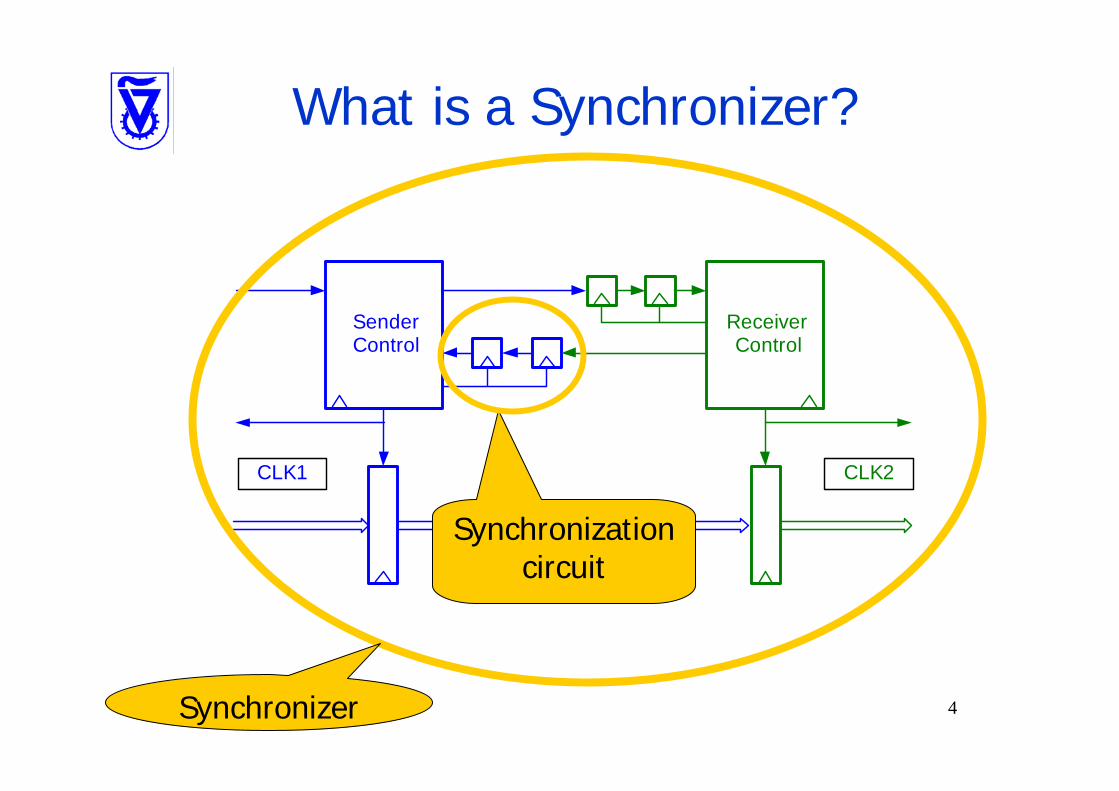
What is a Synchronizer?
SenderControl
ReceiverControl
CLK1 CLK2
Synchronizationcircuit
Synchronizer
5
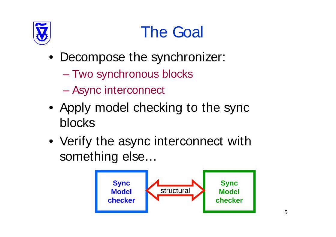
The Goal• Decompose the synchronizer:
– Two synchronous blocks– Async interconnect
• Apply model checking to the sync blocks
• Verify the async interconnect with something else…
SyncModel
checker
SyncModel
checkerstructural
6
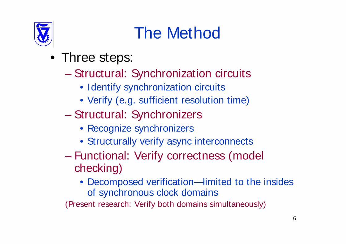
The Method• Three steps:
– Structural: Synchronization circuits• Identify synchronization circuits• Verify (e.g. sufficient resolution time)
– Structural: Synchronizers• Recognize synchronizers • Structurally verify async interconnects
– Functional: Verify correctness (model checking)• Decomposed verification—limited to the insides
of synchronous clock domains(Present research: Verify both domains simultaneously)
7
RuleBase• Model checker by IBM research• Luckily, developed next door…• Input language: Sugar2 / PSL• Inputs:
– The design (Verilog)– The environment (e.g. clocks)– The rules to be verified
• Also used @Verifier / @Designer from @HDL– They incorporate a RuleBase engine
8
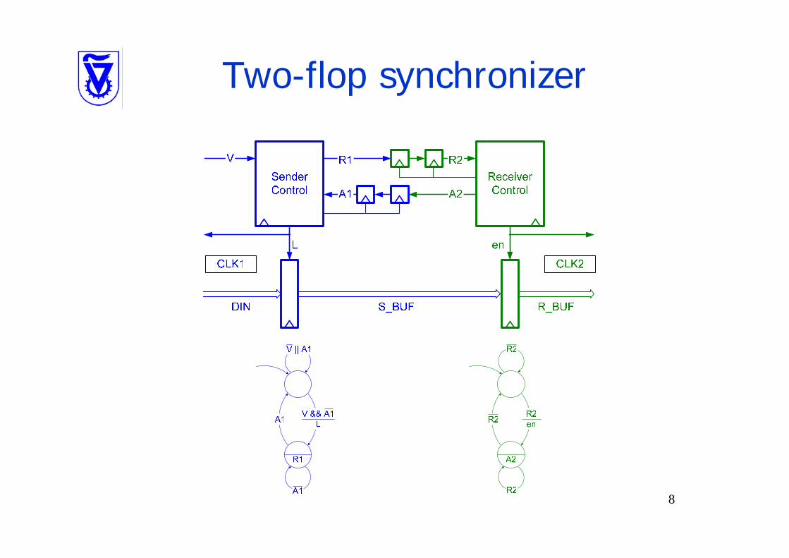
Two-flop synchronizer
9
Outline• The problem• Structural verification• 1CD control functional verification• MCD control functional verification• MCD data functional verification
10
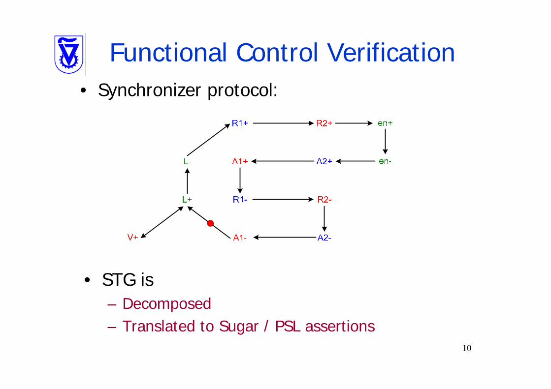
Functional Control Verification• Synchronizer protocol:
• STG is – Decomposed– Translated to Sugar / PSL assertions

11
Decomposed STG
A1+
R1+
R1-L+
L-
A1-
A2+
R2+
R2-
en+
en-
A2-V+
A1+
R1+
R1-L+
L-
A1-
A2+
R2+
R2-
en+
en-
A2-V+
12
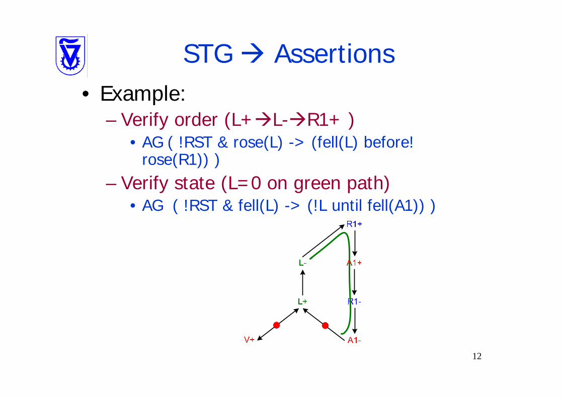
STG Assertions• Example:
– Verify order (L+ L- R1+ )• AG ( !RST & rose(L) -> (fell(L) before!
rose(R1)) )– Verify state (L=0 on green path)
• AG ( !RST & fell(L) -> (!L until fell(A1)) )
13
STG Assertions• Assertions generated for each STG node• Assertions generated automatically
• We have been able to verify simple synchronizers using this method

14
STG Assertions: Problems• Synchronization protocol specific• STG should satisfy some properties
– e.g Complete State Coding: • Every STG node should be distinguishable. In the following
case C+ events are indistinguishable as they may occur during the same state of A and B
Ambiguity:
A=B=1,C+ A-A=B=1,C+ B-

15
STG Assertions: Problems (2)• Exponential complexity
– Same as STG SG:

16
STG Assertions: Problems (3)• Requires splitting the protocol into synchronous
parts– Mitigation: Model asynchronous clocks in RuleBase
17
Outline• The problem• Structural verification• 1CD control functional verification• MCD control functional verification• MCD data functional verification
18
Clock Modeling in RuleBase• The Model Checker operates on a sequence of
“ticks”• RuleBase can model flip-flops in two modes:
– “Level triggered” mode (the default):• FFs sample on ticks when clock level=1
– “Edge triggered” mode:• FFs sample on rising edge of the clock
• Whenever possible we use level-triggered mode clocks

19
Multi-Clock Domain Modeling• Given two un-related clock domains
– Mutually asynchronous clocks
• Each tick, we allow their states to non-deterministically proceed or stall – Non-determinism is achieved by set
assignment (one member is selected in random) :assign state := {value1, value2, …, valueN};
20
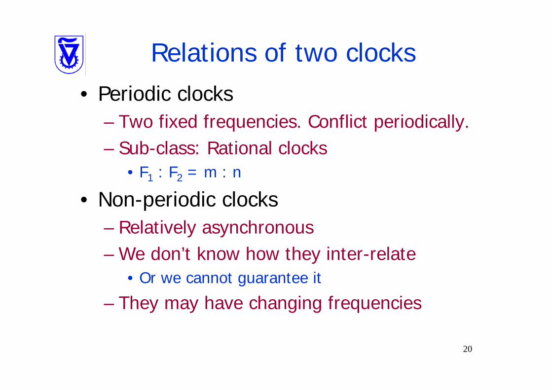
Relations of two clocks• Periodic clocks
– Two fixed frequencies. Conflict periodically.– Sub-class: Rational clocks
• F1 : F2 = m : n
• Non-periodic clocks– Relatively asynchronous– We don’t know how they inter-relate
• Or we cannot guarantee it
– They may have changing frequencies

21
Non-periodic clocks• Declaring unrelated clocks:
VAR CLK1, CLK2: 0..1;fairness CLK1=1;fairness CLK2=1;
• No further assignments into CLK1, CLK2:– Each of them may change non-
deterministically on every tick
• Fairness:– Each clock will change “infinitely” many
times
22
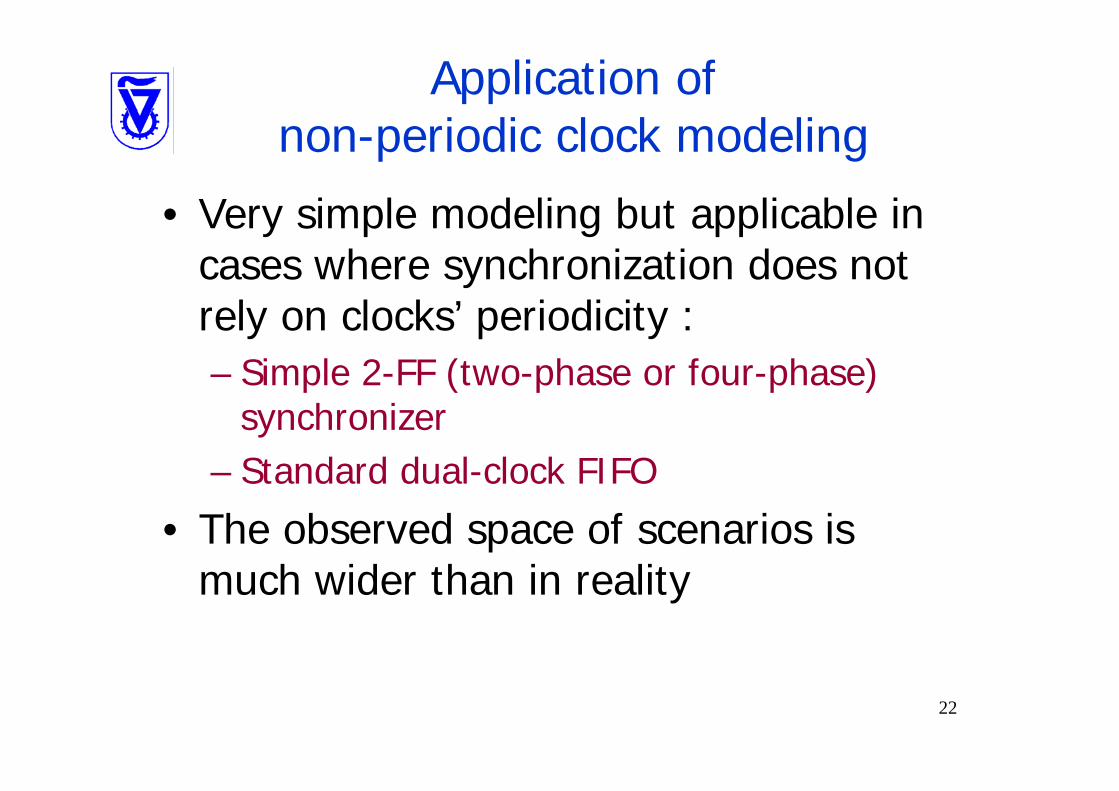
Application of non-periodic clock modeling
• Very simple modeling but applicable in cases where synchronization does not rely on clocks’ periodicity :– Simple 2-FF (two-phase or four-phase)
synchronizer– Standard dual-clock FIFO
• The observed space of scenarios is much wider than in reality
23
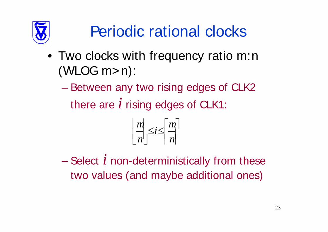
Periodic rational clocks• Two clocks with frequency ratio m:n
(WLOG m>n):– Between any two rising edges of CLK2
there are i rising edges of CLK1:
– Select i non-deterministically from these two values (and maybe additional ones)
m min n⎢ ⎥ ⎡ ⎤≤ ≤⎢ ⎥ ⎢ ⎥⎣ ⎦ ⎢ ⎥

24
Periodic rational clocks• Example: Ratio is 3:2
var c: 0..2;var CLK, CLK2: 0..1;assign next(c) :=if (c != 1) then (c+1) mod 3 else {0, 2};assign CLK1 := c != 0;assign CLK2 := c = 0;
c
CLK1
CLK2
1 2 0 1 0 1 0 1 2
25
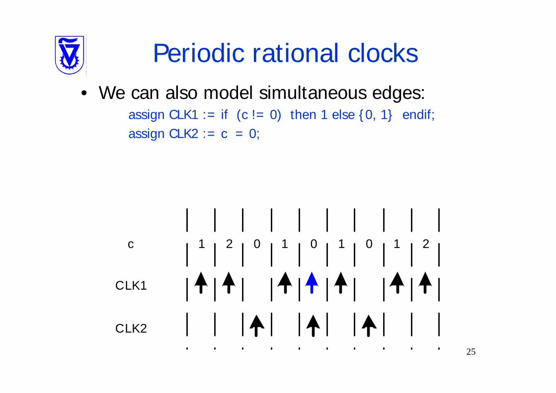
Periodic rational clocks• We can also model simultaneous edges:
assign CLK1 := if (c != 0) then 1 else {0, 1} endif;assign CLK2 := c = 0;
c
CLK1
CLK2
1 2 0 1 0 1 0 1 2

26
Application of periodic clock modeling
• Predictive synchronizer:
Predictive Synchronizer
EXT_CLK LOC_CLK
SEND
RECV
RCLK
CLK1 CLK2
SEND1
RECV2
EN
– When CLK1, CLK2 are too close, data sampling by RCLK is postponed by a predetermined delay
– SEND and RECV indications are generated to avoid misses and duplicates
– Usually, data transfer rate is equal to frequency of the slower sideFrank and Ginosar, “A Predictive Synchronizer for Periodic Clock Domains,” PATMOS 2004.

27
Predictive synchronizer• The receiver can predict conflicts one cycle
in advance (thanks to clock periodicity)• Three conflict detectors are employed:
– Two of them are used infrequently, for tuning – One is used every cycle, hunting for future
conflicts
The Structural Assumption: Half cycle resolution
28
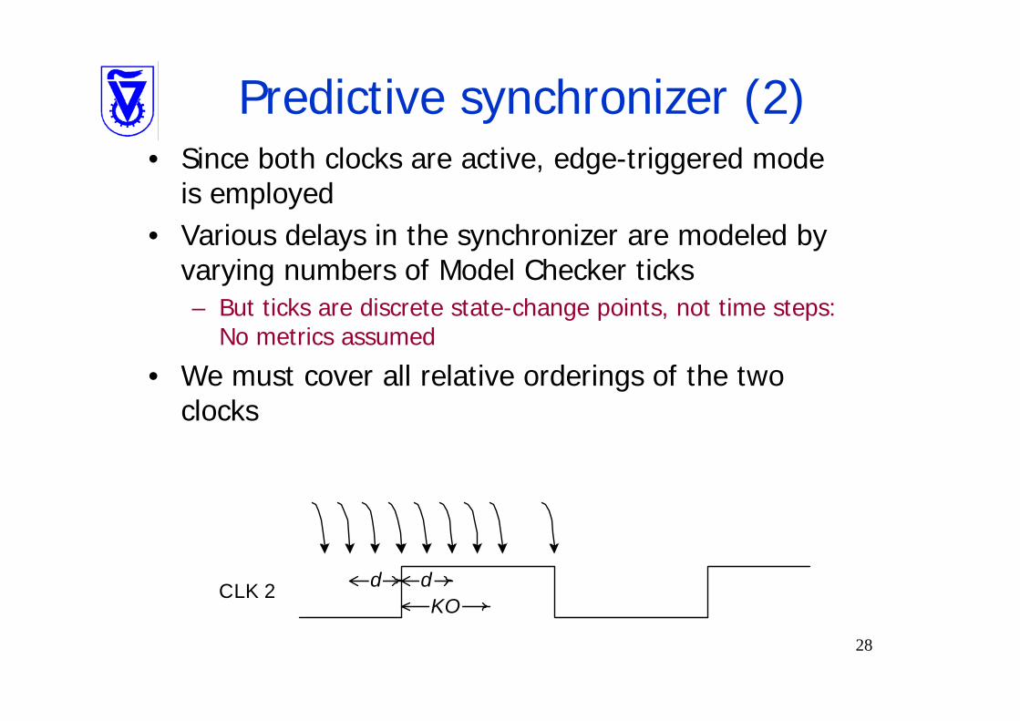
Predictive synchronizer (2)• Since both clocks are active, edge-triggered mode
is employed• Various delays in the synchronizer are modeled by
varying numbers of Model Checker ticks– But ticks are discrete state-change points, not time steps:
No metrics assumed
• We must cover all relative orderings of the two clocks
d dCLK 2KO
29
Predictive synchronizer (3)• All timing / metastability issues are verified
separately by structural verification• Correct operation was verified
– And some errors discovered…

30
Outline• The problem• Structural verification• 1CD control functional verification• MCD control functional verification• MCD data functional verification
31
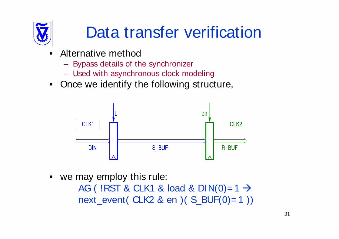
Data transfer verification• Alternative method
– Bypass details of the synchronizer – Used with asynchronous clock modeling
• Once we identify the following structure,
• we may employ this rule:AG ( !RST & CLK1 & load & DIN(0)=1 next_event( CLK2 & en )( S_BUF(0)=1 ))
32
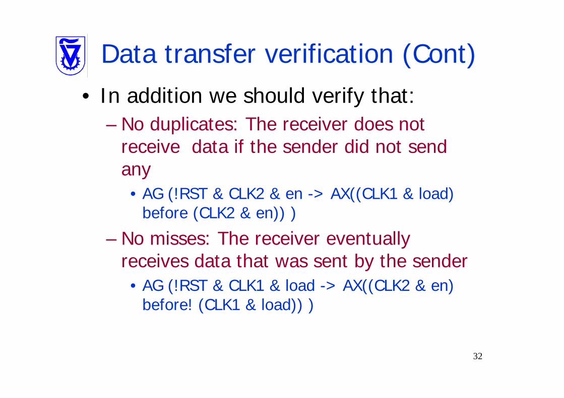
Data transfer verification (Cont)• In addition we should verify that:
– No duplicates: The receiver does not receive data if the sender did not send any• AG (!RST & CLK2 & en -> AX((CLK1 & load)
before (CLK2 & en)) )
– No misses: The receiver eventually receives data that was sent by the sender• AG (!RST & CLK1 & load -> AX((CLK2 & en)
before! (CLK1 & load)) )
33
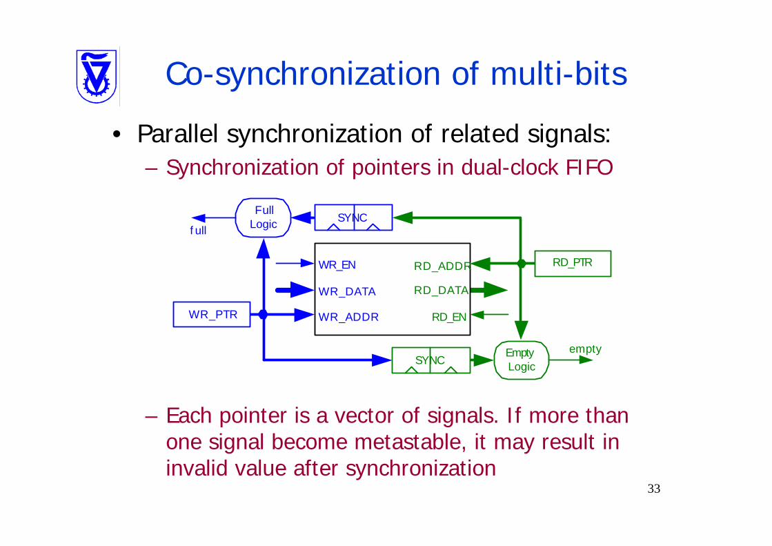
Co-synchronization of multi-bits
• Parallel synchronization of related signals:– Synchronization of pointers in dual-clock FIFO
– Each pointer is a vector of signals. If more than one signal become metastable, it may result in invalid value after synchronization
WR_ADDR
RD_ADDRWR_EN
RD_EN
WR_DATA RD_DATA
WR_PTR
RD_PTR
SYNC
SYNCEmptyLogic
FullLogic
empty
f ull
34
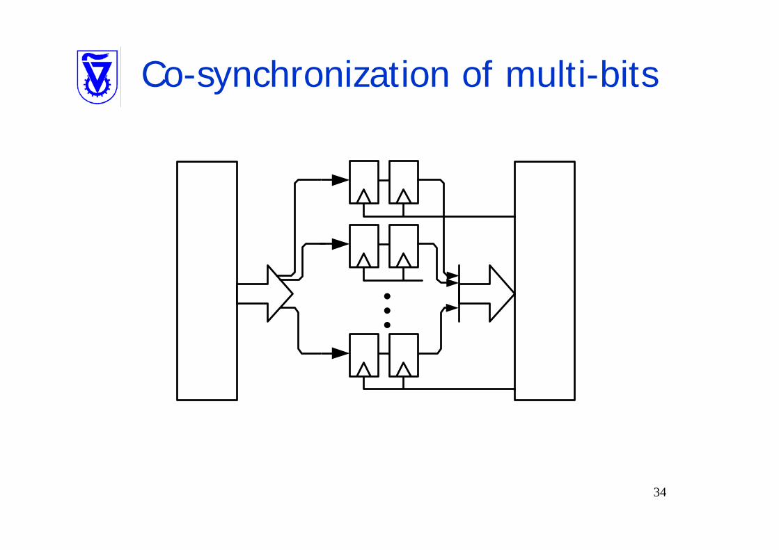
Co-synchronization of multi-bits
35
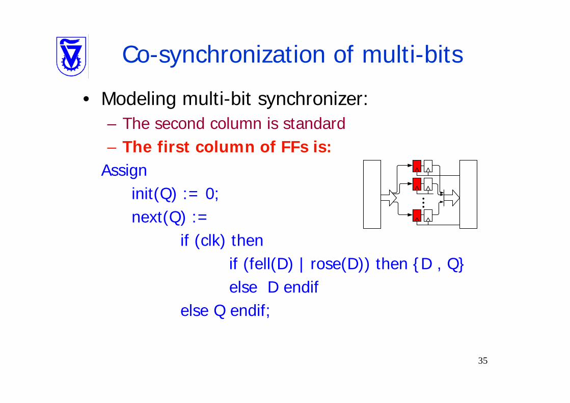
Co-synchronization of multi-bits
• Modeling multi-bit synchronizer: – The second column is standard– The first column of FFs is:
Assigninit(Q) := 0;next(Q) :=
if (clk) then if (fell(D) | rose(D)) then {D , Q}else D endif
else Q endif;
...
36
Summary• Employ model checking for FV of
synchronizers• Two approaches:
– Decompose synchronizers into sync components, verify each separately
– Model two asynchronous clocks
• Verify control and data