Embed Size (px)
Citation preview
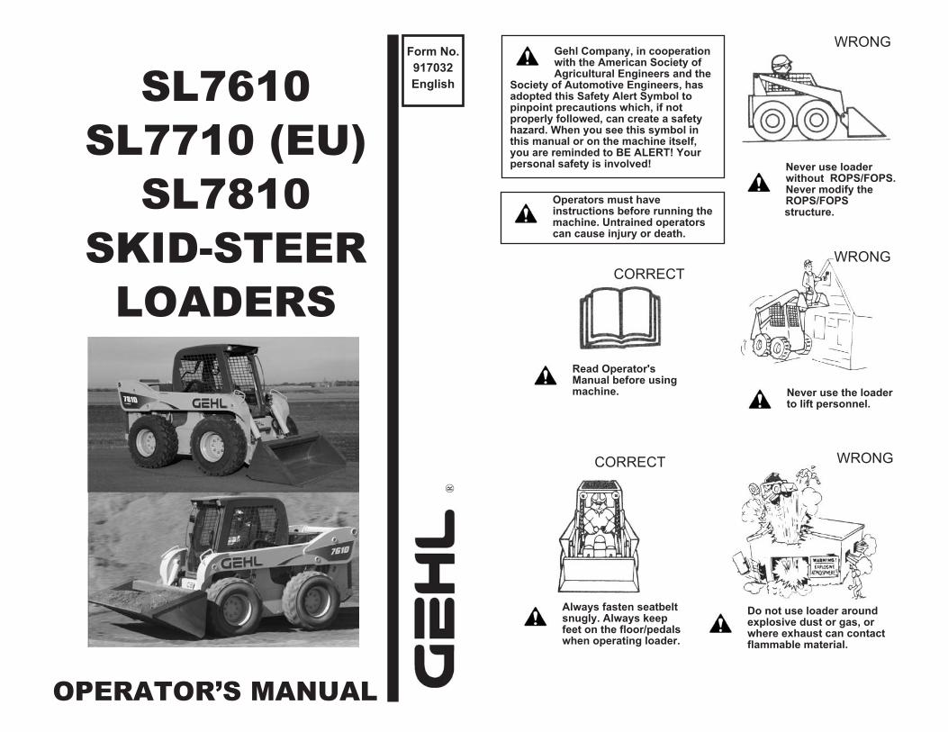
Form No.
917032
EnglishSL7610
SL7710 (EU)
SL7810
SKID-STEER
LOADERS
OPERATOR’S MANUAL
®
Read Operator'sManual before usingmachine.
Gehl Company, in cooperationwith the American Society ofAgricultural Engineers and the
Society of Automotive Engineers, hasadopted this Safety Alert Symbol topinpoint precautions which, if notproperly followed, can create a safetyhazard. When you see this symbol inthis manual or on the machine itself,you are reminded to BE ALERT! Yourpersonal safety is involved!
Always fasten seatbeltsnugly. Always keepfeet on the floor/pedalswhen operating loader.
Never use loaderwithout ROPS/FOPS.Never modify theROPS/FOPSstructure.
Never use the loaderto lift personnel.
Do not use loader aroundexplosive dust or gas, orwhere exhaust can contactflammable material.
Operators must haveinstructions before running themachine. Untrained operatorscan cause injury or death.
WRONG
WRONG
WRONGCORRECT
CORRECT
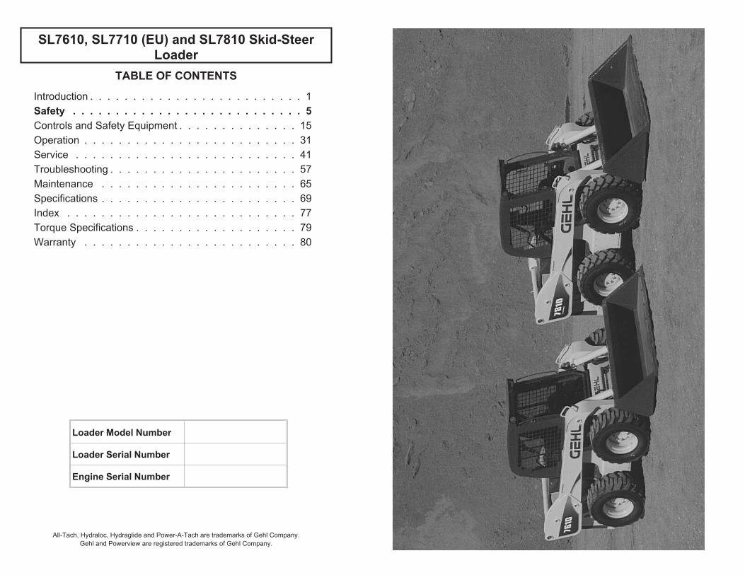
TABLE OF CONTENTS
Introduction . . . . . . . . . . . . . . . . . . . . . . . . . 1
Safety . . . . . . . . . . . . . . . . . . . . . . . . . . . 5
Controls and Safety Equipment . . . . . . . . . . . . . . 15
Operation . . . . . . . . . . . . . . . . . . . . . . . . . 31
Service . . . . . . . . . . . . . . . . . . . . . . . . . . 41
Troubleshooting . . . . . . . . . . . . . . . . . . . . . . 57
Maintenance . . . . . . . . . . . . . . . . . . . . . . . 65
Specifications . . . . . . . . . . . . . . . . . . . . . . . 69
Index . . . . . . . . . . . . . . . . . . . . . . . . . . . 77
Torque Specifications . . . . . . . . . . . . . . . . . . . 79
Warranty . . . . . . . . . . . . . . . . . . . . . . . . . 80
SL7610, SL7710 (EU) and SL7810 Skid-SteerLoader
Loader Model Number
Loader Serial Number
Engine Serial Number
All-Tach, Hydraloc, Hydraglide and Power-A-Tach are trademarks of Gehl Company.
Gehl and Powerview are registered trademarks of Gehl Company.
CHAPTER 1
INTRODUCTIONThis Operator’s Manual provides the
owner/operator information about
maintaining and servicing SL7610, SL
7710 (EU) and SL7810 skid-steer
loader models. More importantly, this
manual provides an operating plan for
safe and proper use of the machine.
Major points of safe operation are
detailed in the Safety chapter of this
manual.
We ask that you read and understand the
contents of this manual completely and
become familiar with your new
machine before operating it. See your
authorized Gehl dealer if you have any
questions concerning information in the
manual, require extra manuals or for
information concerning the availability
of manuals in other languages.
Throughout this manual, information is
provided set in italic type and
introduced by the word Note or
Important. Read carefully and comply
with those messages — it will improve
your operating and maintenance
efficiency, help avoid breakdowns and
damage, and extend your machine’s
life.
A manual storage box in the operator’s
compartment holds the Operator’s
Manual and AEM Safety Manual (also
available in Spanish). Please return the
manuals to this box and keep them with
the unit at all times. If this machine is
resold, we recommend that these
manuals be given to the new owner.
The attachments and equipment
available for use with this machine have
a wide variety of potential applications.
Read the manual provided with the
attachment to learn how to safely
maintain and operate the equipment. Be
sure the machine is suitably equipped
for the type of work to be performed.
Do not use this machine for any
applications or purposes other than
those described in this manual or those
applicable for approved attachments. If
the machine is to be used with special
attachments or equipment other than
those approved by Gehl Company,
consult your Gehl dealer. Any person
using non-approved attachments or
making unauthorized modifications is
responsible for the consequences.
The Gehl dealership network stands
ready to provide you with any
assistance you may require, including
providing genuine Gehl service parts.
All service parts should be obtained
from your Gehl dealer. Provide
complete information about the part and
include the model and serial numbers of
your machine. Record these numbers in
the space provided on the Table of
Contents page, as a handy reference.
Please be aware that Gehl strives to
continuously improve its products and
reserves the right to make changes and
improvements in the design and
construction of any part without
incurring the obligation to install such
changes on any previously delivered
unit.
If this machine was purchased "used,"
or if the owner's address has changed,
please provide your Gehl dealer or Gehl
Company Service Department with the
owner's name and current address,
along with the machine model and
serial number. This will allow the
registered owner information to be
updated, so that the owner can be
notified directly in case of an important
product issue, such as a safety update
program.
917032/BP0404 1
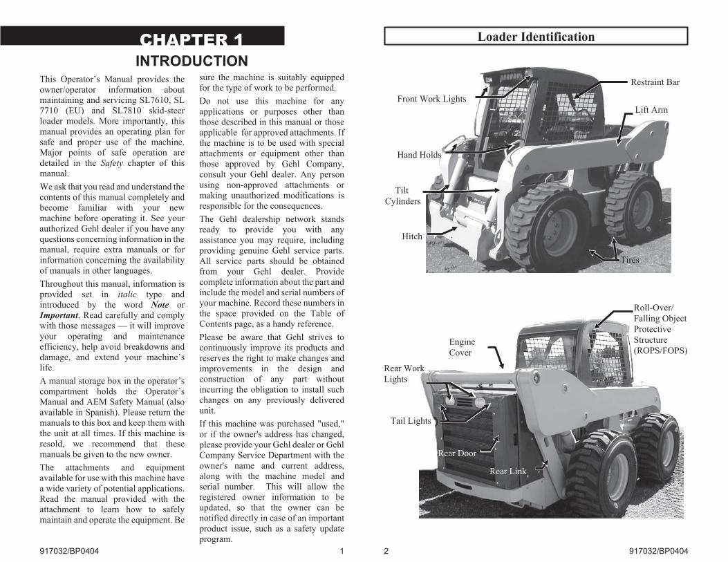
Loader Identification
2 917032/BP0404
Front Work Lights
Hand Holds
Restraint Bar
Hitch
Tires
Engine
Cover
Tail Lights
Rear Door
Lift Arm
Roll-Over/
Falling Object
Protective
Structure
(ROPS/FOPS)
Rear Work
Lights
Rear Link
Tilt
Cylinders
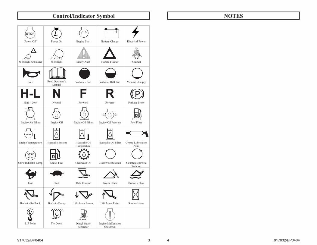
Control/Indicator Symbol
917032/BP0404 3
Power On Engine Start Battery Charge Electrical Power
Worklight w/Flasher Worklight Safety Alert Hazard Flasher Seatbelt
Horn
Power Off
Read Operator’s
ManualVolume - Full Volume- Half Full Volume - Empty
H-LHigh - Low
NNeutral
FForward
RReverse Parking Brake
Engine Air Filter Engine Oil Engine Oil Filter Engine Oil Pressure Fuel Filter
Engine Temperature Hydraulic System Hydraulic Oil
Temperature
Hydraulic Oil Filter Grease Lubrication
Point
Diesel Fuel Chaincase Oil Clockwise Rotation Counterclockwise
Rotation
Fast Slow Ride Control Power Hitch Bucket - Float
Bucket - Rollback Bucket - Dump Lift Arm - Lower Lift Arm - Raise Service Hours
Lift Point Tie-Down
Glow Indicator Lamp
Diesel Water
Separator
Engine Malfunction
Shutdown
NOTES
4 917032/BP0404
CHAPTER 2
SAFETYThis safety alert symbol means
Attention! Become alert! Your
safety is involved! It stresses
an attitude of “Heads Up for Safety”
and can be found throughout this
Operator’s Manual and on the decals on
the machine.
Before operating this machine, read and
study the following safety information.
For further reference on the safe
operation of skid-steer loaders, Gehl
Company suggests that equipment
owners obtain the Gehl “Skid-Steer
Loader Safety” video, which is
available through Gehl dealers. In
addition, be sure that everyone who
operates or works with this machine,
whether family member or employee, is
familiar with these safety precautions. It
is essential to have competent and
careful operators, who are not
physically or mentally impaired, and
who are thoroughly trained in the safe
operation of the machine and the
handling of loads. It is recommended
that the operator be capable of obtaining
a valid motor vehicle operator’s license.
The use of skid-steer loaders is subject
to certain hazards that cannot be
eliminated by mechanical means, but
only by exercising intelligence, care
and common sense. Such hazards
include, but are not limited to, hillside
operation, overloading, instability of
the load, poor maintenance and using
the equipment for a purpose for which it
is not intended or designed.
Gehl ALWAYS considers the operator’s
safety when designing its machinery,
and guards exposed moving parts for
the operator’s protection. However,
some areas cannot be guarded or
shielded in order to assure proper
operation. Furthermore, this Operator’s
Manual and decals on the machine warn
of additional hazards and they should be
read and observed closely.
Some photographs in this manual may
show doors, guards and shields open or
removed for illustrative purposes only.
Be sure that all doors, guards and
shields are in their proper operating
positions before starting the engine to
operate the unit.
Different applications may require
optional safety equipment, such as a
back-up alarm, mirror, strobe light or an
impact-resistant front door. Be sure you
know the job site hazards and equip
your machine as needed.
DANGER
“DANGER” indicates an imminentlyhazardous situation which, if notavoided, will result in death or seriousinjury.
WARNING
“WARNING” indicates a potentiallyhazardous situation which, if notavoided, could result in death orserious injury.
CAUTION
“CAUTION” indicates a potentiallyhazardous situation which, if notavoided may result in minor ormoderate injury. May also alert againstunsafe practices.
917032/BP0404 5
Mandatory SafetyShutdown Procedure
Before cleaning, adjusting, lubricating,
servicing the unit or leaving it
unattended:
1. Move the drive control handle(s) tothe neutral position.
2. Lower the lift arm and attachmentcompletely. If the lift arm must beleft in the raised position, BE SURE
to properly engage the lift armsupport device (page 17).
3. Move the throttle to the low idleposition, shut off the engine andremove the key.
4. Before exiting, move the lift/tiltcontrol(s) to verify that the controlsdo not cause movement of the liftarm and hitch.
Safety Reminders
Before Starting
�Do not modify the ROPS/FOPS
unless instructed to do so in
installation instructions.
Modifications such as welding,
drilling or cutting can weaken the
structure and reduce the protection it
provides. A damaged ROPS/FOPS
cannot be repaired — it must be
replaced.
� To ensure safe operation, replace
damaged or worn-out parts with
genuine Gehl service parts.
�Gehl skid-steer loaders are designed
and intended to be used only with
Gehl attachments or approved
referral attachments. Gehl cannot
be responsible for operator safety if
the loader is used with a
non-approved attachment.
� Remove all trash and debris from
the machine each day, especially in
the engine compartment, to
minimize the risk of fire.
�Always face the loader and use the
handholds and steps when getting on
and off the loader. Do not jump off
the loader.
�Never use starting fluid (ether).
�Walk around the machine and warn
all nearby personnel before starting
the machine.
�Always perform a daily inspection
of the machine before using it. Look
for damage, loose or missing parts,
leaks, etc.
During Operation
�Machine stability is affected by: the
load being carried, the height of the
load, machine speed, abrupt control
movements and driving over uneven
terrain. DISREGARDING ANY OF
THESE FACTORS CAN CAUSE THE
LOADER TO TIP, THROWING THE
OPERATOR OUT OF THE SEAT OR
LOADER, RESULTING IN DEATH OR
SERIOUS INJURY. Therefore:
ALWAYS operate with the seatbelt
fastened and the restraint bar
lowered. Do not exceed the
machine’s Rated Operating Load.
Carry the load low. Move the
controls smoothly and gradually,
and operate at speeds appropriate for
the conditions.
�When operating on inclines or
ramps, always travel with the
heavier end of the loader toward the
6 917032/BP0404
top of the incline for additional
stability.
�Do not raise or drop a loaded bucket
or fork suddenly. Abrupt
movements under load can cause
serious instability.
�Never activate the float function
with the bucket or attachment
loaded or raised, because this will
cause the lift arm to lower rapidly.
�Do not drive too close to an
excavation or ditch; be sure that the
surrounding ground has adequate
strength to support the weight of the
loader and the load.
�Never carry riders. Do not allow
others to ride on the machine or
attachments, because they could fall
or cause an accident.
�Always look to the rear before
backing up the skid-steer loader.
�Operate the controls only from the
operator’s seat.
�Always keep hands and feet inside
the operator’s compartment while
operating the machine.
�New operators must operate the
loader in an open area away from
bystanders. Practice with the
controls until the loader can be
operated safely and efficiently.
� Exhaust fumes can kill. Do not
operate this machine in an enclosed
area unless there is adequate
ventilation.
�When you park the machine and
before you leave the seat, check the
restraint bar for proper operation.
The restraint bar, when raised,
deactivates the lift/tilt controls and
auxiliary hydraulics, and applies the
parking brake.
Maintenance
�Never attempt to by-pass the
keyswitch to start the engine. Use
only the jump starting procedure
detailed in the Operation chapter of
this manual.
�Never use your hands to search for
hydraulic fluid leaks. Instead, use a
piece of paper or cardboard.
Escaping fluid under pressure can be
invisible and can penetrate the skin
and cause serious injury. If any fluid
is injected into your skin, see a
doctor at once. Injected fluid must
be surgically removed by a doctor or
gangrene may result.
�Always wear safety glasses with
side shields when striking metal
against metal. In addition, it is
recommended that a softer (chip-
resistant) material be used to
cushion the blow. Failure to heed
could lead to serious injury to the
eyes or other parts of the body.
�Do not smoke or have any
spark-producing equipment in the
area while filling the fuel tank or
while working on the fuel or
hydraulic systems.
Potential Hazards
A skid-steer loader operator must
ALWAYS be conscious of the working
environment. Operator actions, the
environmental conditions and the job at
hand require the full attention of the
operator so that safety precautions can
be taken.
917032/BP0404 7
ALWAYS maintain a safe distance from
electric power lines and avoid contact
with any electrically charged conductor
or gas line. Accidental contact or
rupture can result in electrocution or an
explosion. Contact the North American
One-Call Referral System at: 1-888-
258-0808 for the local "Digger's
Hotline" number or the proper local
authorities for utility line locations
BEFORE starting to dig!
Exposure to crystalline silica (found in
sand, soil and rocks) has been
associated with silicosis, a debilitating
and often fatal lung disease. A Hazard
Review (Pub. No. 2002-129) by the
U.S. National Institute for Occupational
Safety and Health (NIOSH) indicates a
significant risk of chronic silicosis for
workers exposed to inhaled crystalline
silica over a working lifetime. NIOSH
recommends an exposure limit of 0.05
mg/m3 as a time-weighted average for
up to a 10-hr workday during a 40-hr
workweek. NIOSH also recommends
substituting less hazardous materials
when feasible, using respiratory
protection and regular medical
examinations for exposed workers.
Safety Decals
The skid-steer loader has decals that
provide safety information and
precautions around the loader. These
decals must be kept legible. If missing
or illegible, they must be replaced
promptly. Replacements can be
obtained from your Gehl dealer. New
equipment must have all decals
specified by the manufacturer affixed in
their proper location.
New Decal Application
Surfaces must be free of dirt, dust,
grease and foreign material before
applying the decal. Remove the smaller
portion of the decal backing paper and
apply the exposed adhesive to the clean
surface, maintaining proper position
and alignment. Peel the rest of the
backing paper and apply hand pressure
to smooth out the decal surface. Refer to
the following pages for proper decal
location. Text decals begin on page 9;
no-text decals begin on page 12.
8 917032/BP0404
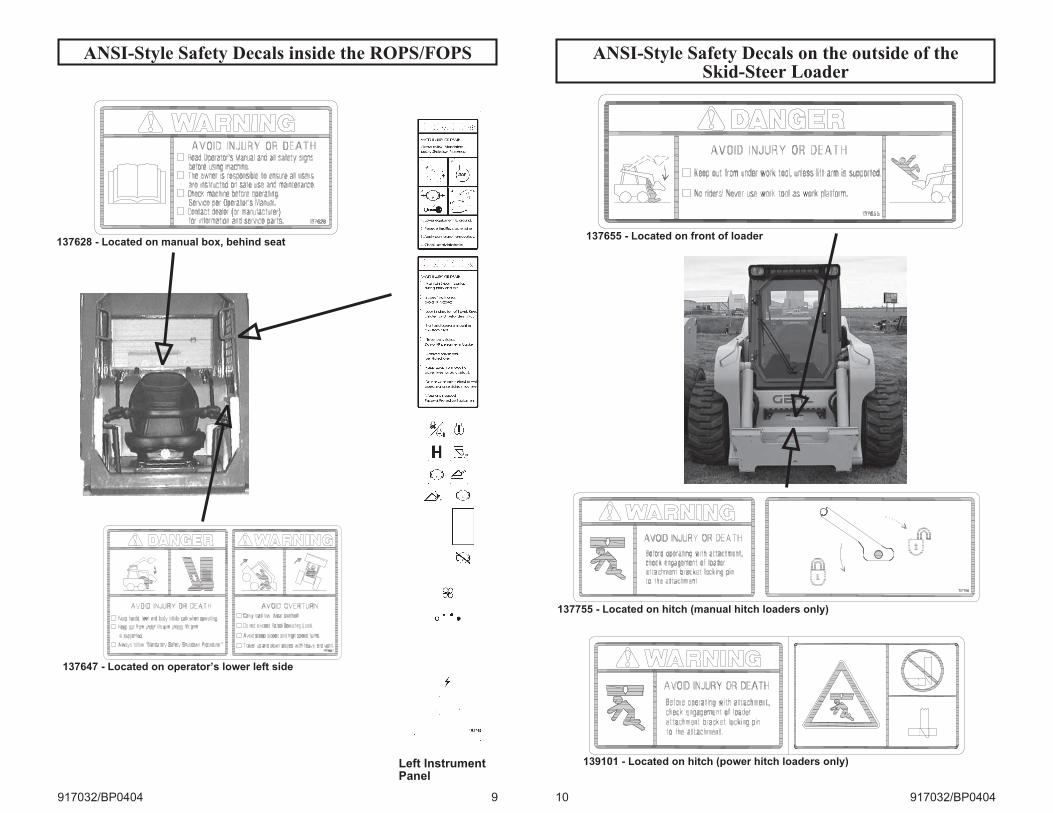
ANSI-Style Safety Decals inside the ROPS/FOPS
917032/BP0404 9
137628 - Located on manual box, behind seat
137647 - Located on operator’s lower left side
Left InstrumentPanel
ANSI-Style Safety Decals on the outside of theSkid-Steer Loader
10 917032/BP0404
137655 - Located on front of loader
137755 - Located on hitch (manual hitch loaders only)
139101 - Located on hitch (power hitch loaders only)
ANSI-Style Safety Decals in the Engine Compartment
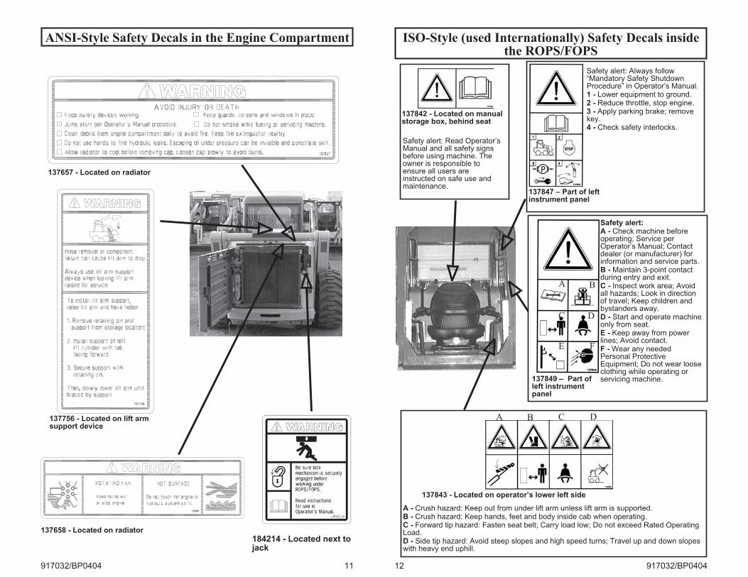
917032/BP0404 11
137657 - Located on radiator
137756 - Located on lift armsupport device
137658 - Located on radiator
184214 - Located next tojack
ISO-Style (used Internationally) Safety Decals insidethe ROPS/FOPS
12 917032/BP0404
137842 - Located on manualstorage box, behind seat
Safety alert: Read Operator’sManual and all safety signsbefore using machine. Theowner is responsible toensure all users areinstructed on safe use andmaintenance.
137843 - Located on operator’s lower left side
A - Crush hazard: Keep out from under lift arm unless lift arm is supported.B - Crush hazard: Keep hands, feet and body inside cab when operating.C - Forward tip hazard: Fasten seat belt; Carry load low; Do not exceed Rated OperatingLoad.D - Side tip hazard: Avoid steep slopes and high speed turns; Travel up and down slopeswith heavy end uphill.
137847 – Part of leftinstrument panel
Safety alert: Always follow“Mandatory Safety ShutdownProcedure” in Operator’s Manual.1 - Lower equipment to ground.2 - Reduce throttle, stop engine.3 - Apply parking brake; removekey.4 - Check safety interlocks.
137849 – Part ofleft instrumentpanel
C
E
Safety alert:A - Check machine beforeoperating; Service perOperator’s Manual; Contactdealer (or manufacturer) forinformation and service parts.B - Maintain 3-point contactduring entry and exit.C - Inspect work area; Avoidall hazards; Look in directionof travel; Keep children andbystanders away.D - Start and operate machineonly from seat.E - Keep away from powerlines; Avoid contact.F - Wear any neededPersonal ProtectiveEquipment; Do not wear looseclothing while operating orservicing machine.
A B
D
F
DCBA
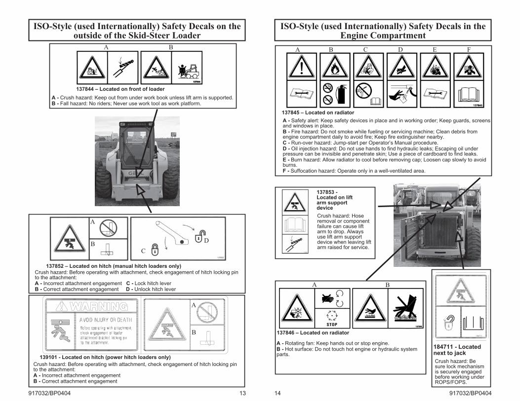
ISO-Style (used Internationally) Safety Decals on theoutside of the Skid-Steer Loader
917032/BP0404 13
137844 – Located on front of loader
137852 – Located on hitch (manual hitch loaders only)
A
BC
D
A - Crush hazard: Keep out from under work book unless lift arm is supported.B - Fall hazard: No riders; Never use work tool as work platform.
Crush hazard: Before operating with attachment, check engagement of hitch locking pinto the attachment:A - Incorrect attachment engagement C - Lock hitch leverB - Correct attachment engagement D - Unlock hitch lever
A B
139101 - Located on hitch (power hitch loaders only)
Crush hazard: Before operating with attachment, check engagement of hitch locking pinto the attachment:A - Incorrect attachment engagementB - Correct attachment engagement
B
A
ISO-Style (used Internationally) Safety Decals in theEngine Compartment
14 917032/BP0404
137853 -Located on liftarm supportdevice
137845 – Located on radiator
A B C D E F
A - Safety alert: Keep safety devices in place and in working order; Keep guards, screensand windows in place.B - Fire hazard: Do not smoke while fueling or servicing machine; Clean debris fromengine compartment daily to avoid fire; Keep fire extinguisher nearby.C - Run-over hazard: Jump-start per Operator’s Manual procedure.D - Oil injection hazard: Do not use hands to find hydraulic leaks; Escaping oil underpressure can be invisible and penetrate skin; Use a piece of cardboard to find leaks.E - Burn hazard: Allow radiator to cool before removing cap; Loosen cap slowly to avoidburns.F - Suffocation hazard: Operate only in a well-ventilated area.
137846 – Located on radiator
A B
A - Rotating fan: Keep hands out or stop engine.B - Hot surface: Do not touch hot engine or hydraulic systemparts.
Crush hazard: Hoseremoval or componentfailure can cause liftarm to drop. Alwaysuse lift arm supportdevice when leaving liftarm raised for service.
184711
184711 - Locatednext to jack
Crush hazard: Besure lock mechanismis securely engagedbefore working underROPS/FOPS.
CHAPTER 3
CONTROLS AND SAFETY EQUIPMENT
WARNING
Become familiar with and know how touse all safety devices and controls onthe skid-steer loader before operatingit. Know how to stop loader operationbefore starting it. This Gehl loader isdesigned and intended to be used onlywith a Gehl attachment or aGehl-approved referral attachment oraccessory. Gehl cannot beresponsible for operator safety if theloader is used with a non-approvedattachment.
Guards and Shields
Whenever possible and without
affecting loader operation, guards and
shields are provided to protect against
potentially hazardous areas. In many
places, safety decals are also provided
to warn of potential hazards and/or to
display special operating procedures.
WARNING
Read and thoroughly understand allsafety decals on the loader beforeoperating it. Do not operate the loaderunless all factory-installed guards andshields are properly secured in place.
Operator Restraint Bar
Lower the restraint bar after entering
the operator’s compartment. The
restraint bar is securely anchored to the
ROPS/FOPS. The restraint bar switch
and the seat switch form an interlock for
the lift arm, tilt, drive and starter circuits
(refer to the “Safety Interlock System”
topic on page 16 for more information).
WARNING
Never defeat the operator restraint baror seat switch electrically ormechanically. Always wear yourseatbelt.
Operator’s Seat
The seat is mounted on rails for
rearward or forward repositioning. A
spring-loaded latch handle activates the
seat adjustment mechanism.
Suspension seat (optional on 7610): Aweight adjustment knob is providedwith this seat for operator adjustment.
Upper-Torso Restraint
WARNING
Always wear the upper-torso restraintwhen operating in high speed.
The seat belt should always be fastened
during operation.
917032/BP0404 15
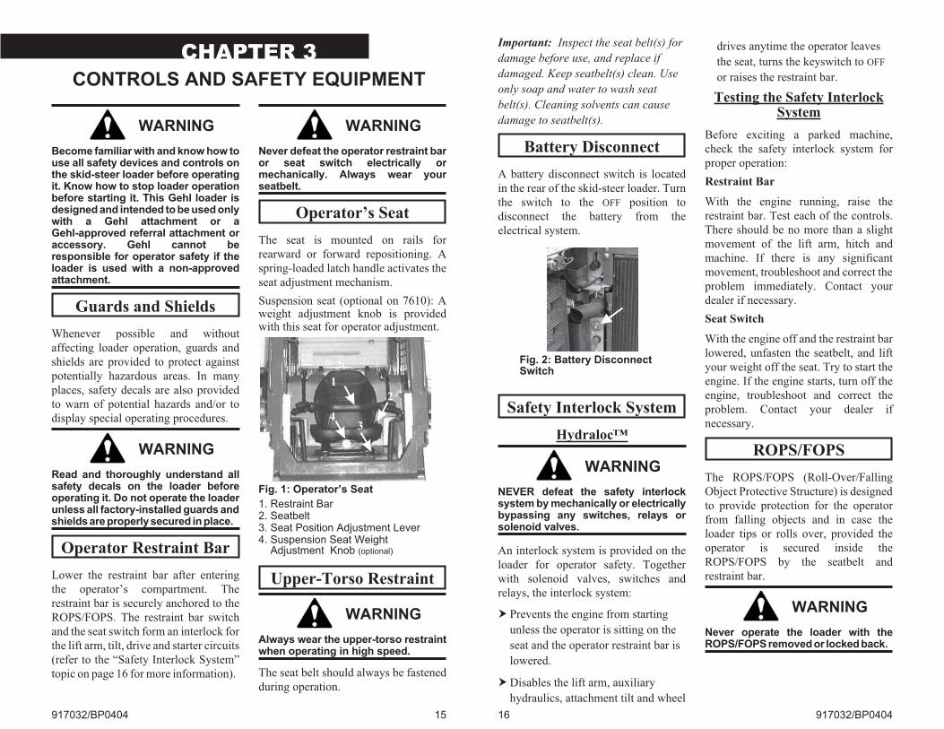
Fig. 1: Operator’s Seat
1. Restraint Bar2. Seatbelt3. Seat Position Adjustment Lever4. Suspension Seat Weight
Adjustment Knob (optional)
1
3
2
4
Important: Inspect the seat belt(s) for
damage before use, and replace if
damaged. Keep seatbelt(s) clean. Use
only soap and water to wash seat
belt(s). Cleaning solvents can cause
damage to seatbelt(s).
Battery Disconnect
A battery disconnect switch is located
in the rear of the skid-steer loader. Turn
the switch to the OFF position to
disconnect the battery from the
electrical system.
Safety Interlock System
Hydraloc™
WARNING
NEVER defeat the safety interlocksystem by mechanically or electricallybypassing any switches, relays orsolenoid valves.
An interlock system is provided on the
loader for operator safety. Together
with solenoid valves, switches and
relays, the interlock system:
� Prevents the engine from starting
unless the operator is sitting on the
seat and the operator restraint bar is
lowered.
�Disables the lift arm, auxiliary
hydraulics, attachment tilt and wheel
drives anytime the operator leaves
the seat, turns the keyswitch to OFF
or raises the restraint bar.
Testing the Safety InterlockSystem
Before exciting a parked machine,
check the safety interlock system for
proper operation:
Restraint Bar
With the engine running, raise the
restraint bar. Test each of the controls.
There should be no more than a slight
movement of the lift arm, hitch and
machine. If there is any significant
movement, troubleshoot and correct the
problem immediately. Contact your
dealer if necessary.
Seat Switch
With the engine off and the restraint bar
lowered, unfasten the seatbelt, and lift
your weight off the seat. Try to start the
engine. If the engine starts, turn off the
engine, troubleshoot and correct the
problem. Contact your dealer if
necessary.
ROPS/FOPS
The ROPS/FOPS (Roll-Over/Falling
Object Protective Structure) is designed
to provide protection for the operator
from falling objects and in case the
loader tips or rolls over, provided the
operator is secured inside the
ROPS/FOPS by the seatbelt and
restraint bar.
WARNING
Never operate the loader with theROPS/FOPS removed or locked back.
16 917032/BP0404
Fig. 2: Battery DisconnectSwitch
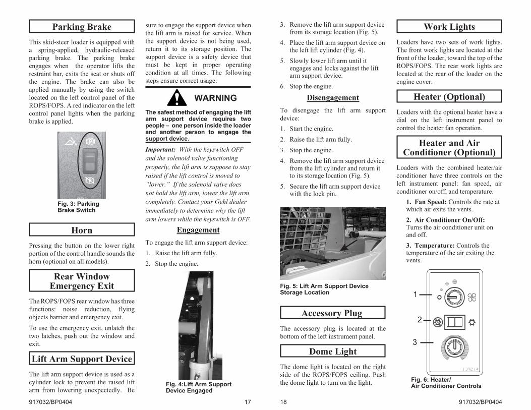
Parking Brake
This skid-steer loader is equipped with
a spring-applied, hydraulic-released
parking brake. The parking brake
engages when the operator lifts the
restraint bar, exits the seat or shuts off
the engine. The brake can also be
applied manually by using the switch
located on the left control panel of the
ROPS/FOPS. A red indicator on the left
control panel lights when the parking
brake is applied.
Horn
Pressing the button on the lower right
portion of the control handle sounds the
horn (optional on all models).
Rear WindowEmergency Exit
The ROPS/FOPS rear window has three
functions: noise reduction, flying
objects barrier and emergency exit.
To use the emergency exit, unlatch the
two latches, push out the window and
exit.
Lift Arm Support Device
The lift arm support device is used as a
cylinder lock to prevent the raised lift
arm from lowering unexpectedly. Be
sure to engage the support device when
the lift arm is raised for service. When
the support device is not being used,
return it to its storage position. The
support device is a safety device that
must be kept in proper operating
condition at all times. The following
steps ensure correct usage:
WARNING
The safest method of engaging the liftarm support device requires twopeople – one person inside the loaderand another person to engage thesupport device.
Important: With the keyswitch OFF
and the solenoid valve functioning
properly, the lift arm is suppose to stay
raised if the lift control is moved to
“lower.” If the solenoid valve does
not hold the lift arm, lower the lift arm
completely. Contact your Gehl dealer
immediately to determine why the lift
arm lowers while the keyswitch is OFF.
Engagement
To engage the lift arm support device:
1. Raise the lift arm fully.
2. Stop the engine.
917032/BP0404 17
Fig. 3: ParkingBrake Switch
Fig. 4:Lift Arm SupportDevice Engaged
3. Remove the lift arm support devicefrom its storage location (Fig. 5).
4. Place the lift arm support device onthe left lift cylinder (Fig. 4).
5. Slowly lower lift arm until itengages and locks against the liftarm support device.
6. Stop the engine.
Disengagement
To disengage the lift arm support
device:
1. Start the engine.
2. Raise the lift arm fully.
3. Stop the engine.
4. Remove the lift arm support devicefrom the lift cylinder and return itto its storage location (Fig. 5).
5. Secure the lift arm support devicewith the lock pin.
Accessory Plug
The accessory plug is located at the
bottom of the left instrument panel.
Dome Light
The dome light is located on the right
side of the ROPS/FOPS ceiling. Push
the dome light to turn on the light.
Work Lights
Loaders have two sets of work lights.
The front work lights are located at the
front of the loader, toward the top of the
ROPS/FOPS. The rear work lights are
located at the rear of the loader on the
engine cover.
Heater (Optional)
Loaders with the optional heater have a
dial on the left instrument panel to
control the heater fan operation.
Heater and AirConditioner (Optional)
Loaders with the combined heater/air
conditioner have three controls on the
left instrument panel: fan speed, air
conditioner on/off, and temperature.
1. Fan Speed: Controls the rate atwhich air exits the vents.
2. Air Conditioner On/Off:Turns the air conditioner unit onand off.
3. Temperature: Controls thetemperature of the air exiting thevents.
18 917032/BP0404
Fig. 5: Lift Arm Support DeviceStorage Location
Fig. 6: Heater/Air Conditioner Controls
3
1
2
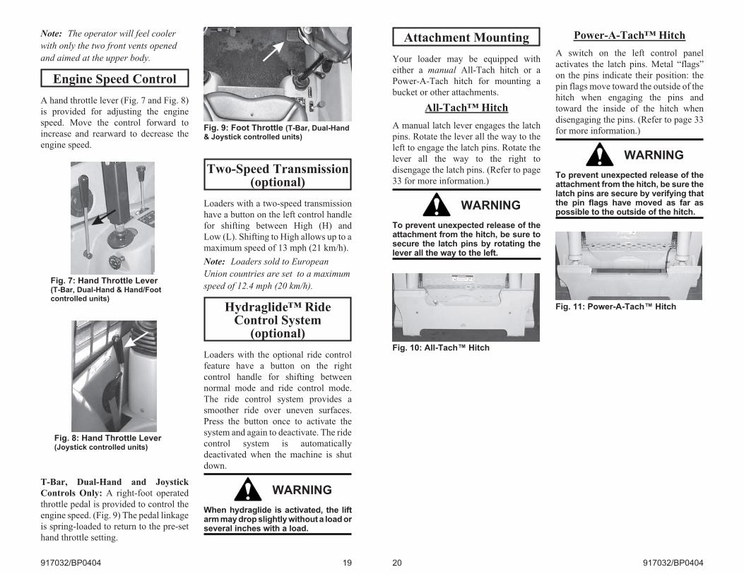
Note: The operator will feel cooler
with only the two front vents opened
and aimed at the upper body.
Engine Speed Control
A hand throttle lever (Fig. 7 and Fig. 8)
is provided for adjusting the engine
speed. Move the control forward to
increase and rearward to decrease the
engine speed.
T-Bar, Dual-Hand and Joystick
Controls Only: A right-foot operated
throttle pedal is provided to control the
engine speed. (Fig. 9) The pedal linkage
is spring-loaded to return to the pre-set
hand throttle setting.
Two-Speed Transmission(optional)
Loaders with a two-speed transmission
have a button on the left control handle
for shifting between High (H) and
Low (L). Shifting to High allows up to a
maximum speed of 13 mph (21 km/h).
Note: Loaders sold to European
Union countries are set to a maximum
speed of 12.4 mph (20 km/h).
Hydraglide™ RideControl System
(optional)
Loaders with the optional ride control
feature have a button on the right
control handle for shifting between
normal mode and ride control mode.
The ride control system provides a
smoother ride over uneven surfaces.
Press the button once to activate the
system and again to deactivate. The ride
control system is automatically
deactivated when the machine is shut
down.
WARNING
When hydraglide is activated, the liftarm may drop slightly without a load orseveral inches with a load.
917032/BP0404 19
Fig. 7: Hand Throttle Lever(T-Bar, Dual-Hand & Hand/Footcontrolled units)
Fig. 8: Hand Throttle Lever(Joystick controlled units)
Fig. 9: Foot Throttle (T-Bar, Dual-Hand& Joystick controlled units)
Attachment Mounting
Your loader may be equipped with
either a manual All-Tach hitch or a
Power-A-Tach hitch for mounting a
bucket or other attachments.
All-Tach™ Hitch
A manual latch lever engages the latch
pins. Rotate the lever all the way to the
left to engage the latch pins. Rotate the
lever all the way to the right to
disengage the latch pins. (Refer to page
33 for more information.)
WARNING
To prevent unexpected release of theattachment from the hitch, be sure tosecure the latch pins by rotating thelever all the way to the left.
Power-A-Tach™ Hitch
A switch on the left control panel
activates the latch pins. Metal “flags”
on the pins indicate their position: the
pin flags move toward the outside of the
hitch when engaging the pins and
toward the inside of the hitch when
disengaging the pins. (Refer to page 33
for more information.)
WARNING
To prevent unexpected release of theattachment from the hitch, be sure thelatch pins are secure by verifying thatthe pin flags have moved as far aspossible to the outside of the hitch.
20 917032/BP0404
Fig. 10: All-Tach™ Hitch
Fig. 11: Power-A-Tach™ Hitch
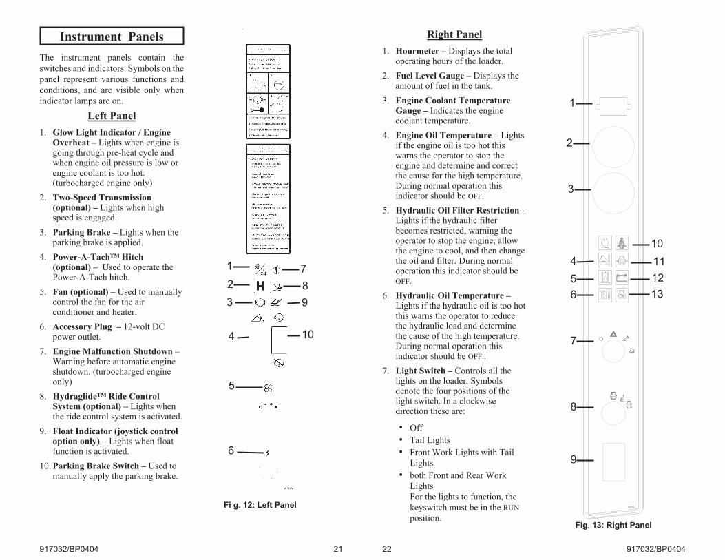
Instrument Panels
The instrument panels contain the
switches and indicators. Symbols on the
panel represent various functions and
conditions, and are visible only when
indicator lamps are on.
Left Panel
1. Glow Light Indicator / EngineOverheat – Lights when engine isgoing through pre-heat cycle andwhen engine oil pressure is low orengine coolant is too hot.(turbocharged engine only)
2. Two-Speed Transmission(optional) – Lights when highspeed is engaged.
3. Parking Brake – Lights when theparking brake is applied.
4. Power-A-Tach™ Hitch(optional) – Used to operate thePower-A-Tach hitch.
5. Fan (optional) – Used to manuallycontrol the fan for the airconditioner and heater.
6. Accessory Plug – 12-volt DCpower outlet.
7. Engine Malfunction Shutdown –Warning before automatic engineshutdown. (turbocharged engineonly)
8. Hydraglide™ Ride ControlSystem (optional) – Lights whenthe ride control system is activated.
9. Float Indicator (joystick controloption only) – Lights when floatfunction is activated.
10. Parking Brake Switch – Used tomanually apply the parking brake.
917032/BP0404 21
Fi g. 12: Left Panel
9
8
6
2
3
5
4
1 7
10
Right Panel
1. Hourmeter – Displays the totaloperating hours of the loader.
2. Fuel Level Gauge – Displays theamount of fuel in the tank.
3. Engine Coolant TemperatureGauge – Indicates the enginecoolant temperature.
4. Engine Oil Temperature – Lightsif the engine oil is too hot thiswarns the operator to stop theengine and determine and correctthe cause for the high temperature.During normal operation thisindicator should be OFF.
5. Hydraulic Oil Filter Restriction–Lights if the hydraulic filterbecomes restricted, warning theoperator to stop the engine, allowthe engine to cool, and then changethe oil and filter. During normaloperation this indicator should beOFF.
6. Hydraulic Oil Temperature –Lights if the hydraulic oil is too hotthis warns the operator to reducethe hydraulic load and determinethe cause of the high temperature.During normal operation thisindicator should be OFF..
7. Light Switch – Controls all thelights on the loader. Symbolsdenote the four positions of thelight switch. In a clockwisedirection these are:
• Off
• Tail Lights
• Front Work Lights with Tail
Lights
• both Front and Rear Work
Lights
For the lights to function, the
keyswitch must be in the RUN
position.
22 917032/BP0404
183749
STOP
Fig. 13: Right Panel
10
11
12
13
1
2
3
4
5
6
7
8
9
8. Keyswitch – In a clockwiserotation, these positions are:
• OFF Position – With the key
vertical, power from the battery
is disconnected from the
controls and instrument panel
electrical circuits. This is the
only position the key can be
inserted or removed from the
keyswitch.
• ON (or RUN) Position – With
the key turned one position
clockwise from vertical, power
from the battery is supplied to
all control and instrument panel
circuits.
• START Position – With the
key turned fully clockwise, the
electric starter energizes, start
the engine. Release the key to
RUN position after the engine
starts.Note: The engine cannot be startedunless the operator is sitting in the seatand the restraint bar is lowered.
9. Glow Plug Rocker (NaturallyAspirated Engines only) – Lightswhen pressed on activeengagement.
10. Fasten Seatbelt – A momentaryvisual (and audible) indicator toremind the operator to fasten theseatbelt(s).
11. Engine Oil Pressure – Lights ifthe engine oil pressure is too low.Warns the operator to immediatelystop the engine and determine thecause for the low pressure. Duringnormal operation this indicatorshould be OFF.
12. Battery – Lights if the chargingvoltage is too high or too low.During normal operation thisindicator should be OFF.
13. Preheat Indicator Lamp(Naturally Aspirated Enginesonly) – Lights when the preheat isactive. During normal operationthis indicator should be OFF
917032/BP0404 23
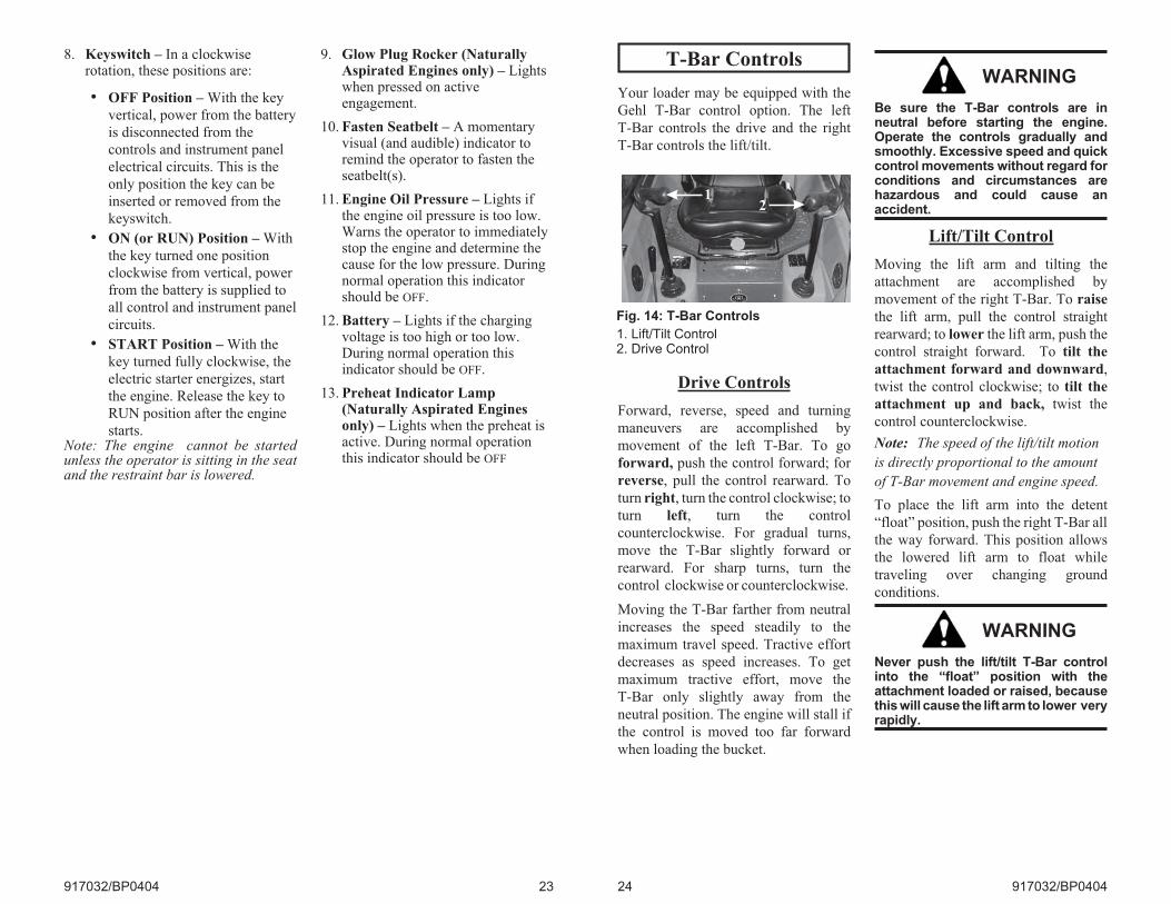
T-Bar Controls
Your loader may be equipped with the
Gehl T-Bar control option. The left
T-Bar controls the drive and the right
T-Bar controls the lift/tilt.
Drive Controls
Forward, reverse, speed and turning
maneuvers are accomplished by
movement of the left T-Bar. To go
forward, push the control forward; for
reverse, pull the control rearward. To
turn right, turn the control clockwise; to
turn left, turn the control
counterclockwise. For gradual turns,
move the T-Bar slightly forward or
rearward. For sharp turns, turn the
control clockwise or counterclockwise.
Moving the T-Bar farther from neutral
increases the speed steadily to the
maximum travel speed. Tractive effort
decreases as speed increases. To get
maximum tractive effort, move the
T-Bar only slightly away from the
neutral position. The engine will stall if
the control is moved too far forward
when loading the bucket.
WARNING
Be sure the T-Bar controls are inneutral before starting the engine.Operate the controls gradually andsmoothly. Excessive speed and quickcontrol movements without regard forconditions and circumstances arehazardous and could cause anaccident.
Lift/Tilt Control
Moving the lift arm and tilting the
attachment are accomplished by
movement of the right T-Bar. To raise
the lift arm, pull the control straight
rearward; to lower the lift arm, push the
control straight forward. To tilt the
attachment forward and downward,
twist the control clockwise; to tilt the
attachment up and back, twist the
control counterclockwise.
Note: The speed of the lift/tilt motion
is directly proportional to the amount
of T-Bar movement and engine speed.
To place the lift arm into the detent
“float” position, push the right T-Bar all
the way forward. This position allows
the lowered lift arm to float while
traveling over changing ground
conditions.
WARNING
Never push the lift/tilt T-Bar controlinto the “float” position with theattachment loaded or raised, becausethis will cause the lift arm to lower veryrapidly.
24 917032/BP0404
Fig. 14: T-Bar Controls
1. Lift/Tilt Control2. Drive Control
12
Joystick Controls
Your loader may be equipped with the
joystick control option. The left joystick
controls the drive and the right joystick
controls the lift/tilt.
Drive Controls
Forward, reverse, speed and turning
maneuvers are accomplished by
movement of the left joystick. To go
forward, push the control forward; for
reverse, pull the control rearward. To
turn right, push the control right; to turn
left, push the control left. To go
forward and left, move the control
forward and left. To go forward and
right, move the control forward and
right. To go back and left, move the
control back and to the right. To go
back and right, move the control back
and to the left.
WARNING
Be sure the joystick controls are inneutral before starting the engine.Operate the controls gradually andsmoothly. Excessive speed and quickcontrol movements without regard forconditions and circumstances arehazardous and could cause anaccident.
Moving the joystick farther from
neutral increases the speed steadily to
the maximum travel speed. Tractive
effort decreases as speed increases. To
get maximum tractive effort, move the
joystick only slightly away from the
neutral position. The engine will stall if
the control is moved too far forward
when loading the bucket.
Lift/Tilt Control
Moving the lift arm and tilting the
attachment are accomplished by
movement of the right joystick. To
raise the lift arm, pull the control
straight rearward; to lower the lift arm,
push the control straight forward. To
tilt the attachment forward and
downward, move the control to the
right; to tilt the attachment up and
back, move the control to the left.
Note: The speed of the lift/tilt motion
is directly proportional to the amount
of joystick movement and engine
speed.
To place the lift arm into the “float”
position, push and hold the left button
on the right joystick. This mode allows
the lowered lift arm to follow the
ground contour while traveling over
changing ground conditions. An
indicator light in the left instrument
panel will blink when the float is
activated.
WARNING
Never push the float control buttonwith the attachment loaded or raised,because this will cause the lift arm tolower very rapidly.
Releasing the float button will cancel
the float mode if the button was pressed
less than five seconds. If the float mode
button is pressed longer than five
seconds, the float feature will stay on
and the float indicator will light
continuously until the button is pressed
again.
917032/BP0404 25
Fig. 15: Joystick Controls
1. Lift/Tilt Control
2. Drive Control
1 2
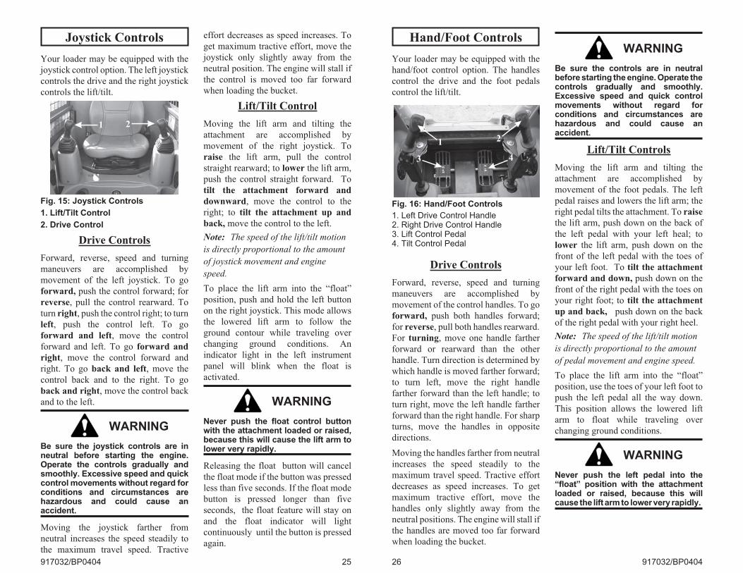
Hand/Foot Controls
Your loader may be equipped with the
hand/foot control option. The handles
control the drive and the foot pedals
control the lift/tilt.
Drive Controls
Forward, reverse, speed and turning
maneuvers are accomplished by
movement of the control handles. To go
forward, push both handles forward;
for reverse, pull both handles rearward.
For turning, move one handle farther
forward or rearward than the other
handle. Turn direction is determined by
which handle is moved farther forward;
to turn left, move the right handle
farther forward than the left handle; to
turn right, move the left handle farther
forward than the right handle. For sharp
turns, move the handles in opposite
directions.
Moving the handles farther from neutral
increases the speed steadily to the
maximum travel speed. Tractive effort
decreases as speed increases. To get
maximum tractive effort, move the
handles only slightly away from the
neutral positions. The engine will stall if
the handles are moved too far forward
when loading the bucket.
WARNING
Be sure the controls are in neutralbefore starting the engine. Operate thecontrols gradually and smoothly.Excessive speed and quick controlmovements without regard forconditions and circumstances arehazardous and could cause anaccident.
Lift/Tilt Controls
Moving the lift arm and tilting the
attachment are accomplished by
movement of the foot pedals. The left
pedal raises and lowers the lift arm; the
right pedal tilts the attachment. To raise
the lift arm, push down on the back of
the left pedal with your left heal; to
lower the lift arm, push down on the
front of the left pedal with the toes of
your left foot. To tilt the attachment
forward and down, push down on the
front of the right pedal with the toes on
your right foot; to tilt the attachment
up and back, push down on the back
of the right pedal with your right heel.
Note: The speed of the lift/tilt motion
is directly proportional to the amount
of pedal movement and engine speed.
To place the lift arm into the “float”
position, use the toes of your left foot to
push the left pedal all the way down.
This position allows the lowered lift
arm to float while traveling over
changing ground conditions.
WARNING
Never push the left pedal into the“float” position with the attachmentloaded or raised, because this willcause the lift arm to lower very rapidly.
26 917032/BP0404
Fig. 16: Hand/Foot Controls
1. Left Drive Control Handle2. Right Drive Control Handle3. Lift Control Pedal4. Tilt Control Pedal
3
1 2
4
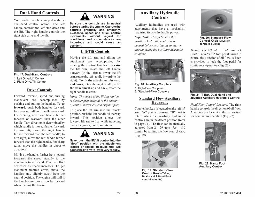
Dual-Hand Controls
Your loader may be equipped with the
dual-hand control option. The left
handle controls the left side drive and
the lift. The right handle controls the
right side drive and the tilt.
Drive Controls
Forward, reverse, speed and turning
maneuvers are accomplished by
pushing and pulling the handles. To go
forward, push both handles forward;
for reverse, pull both handles rearward.
For turning, move one handle farther
forward or rearward than the other
handle. Turn direction is determined by
which handle is moved farther forward;
to turn left, move the right handle
farther forward than the left handle; to
turn right, move the left handle farther
forward than the right handle. For sharp
turns, move the handles in opposite
directions.
Moving the handles farther from neutral
increases the speed steadily to the
maximum travel speed. Tractive effort
decreases as speed increases. To get
maximum tractive effort, move the
handles only slightly away from the
neutral position. The engine will stall if
the handles are moved too far forward
when loading the bucket.
WARNING
Be sure the controls are in neutralbefore starting the engine. Operate thecontrols gradually and smoothly.Excessive speed and quick controlmovements without regard forconditions and circumstances arehazardous and could cause anaccident.
Lift/Tilt Controls
Moving the lift arm and tilting the
attachment are accomplished by
rotating the control handles. To raise
the lift arm, rotate the left handle
outward (to the left); to lower the lift
arm, rotate the left handle inward (to the
right). To tilt the attachment forward
and down, rotate the right handle; to tilt
the attachment up and back, rotate the
right handle inward.
Note: The speed of the lift/tilt motion
is directly proportional to the amount
of control movement and engine speed.
To place the lift arm into the “float”
position, push the left handle all the way
inward. This position allows the
lowered lift arm to float while traveling
over changing ground conditions.
WARNING
Never push the lift/tilt control into the“float” position with the attachmentloaded or raised, because this willcause the lift arm to lower very rapidly.
917032/BP0404 27
Fig. 17: Dual-Hand Controls
1. Left Drive/Lift Control2. Right Drive/Tilt Control
1 2
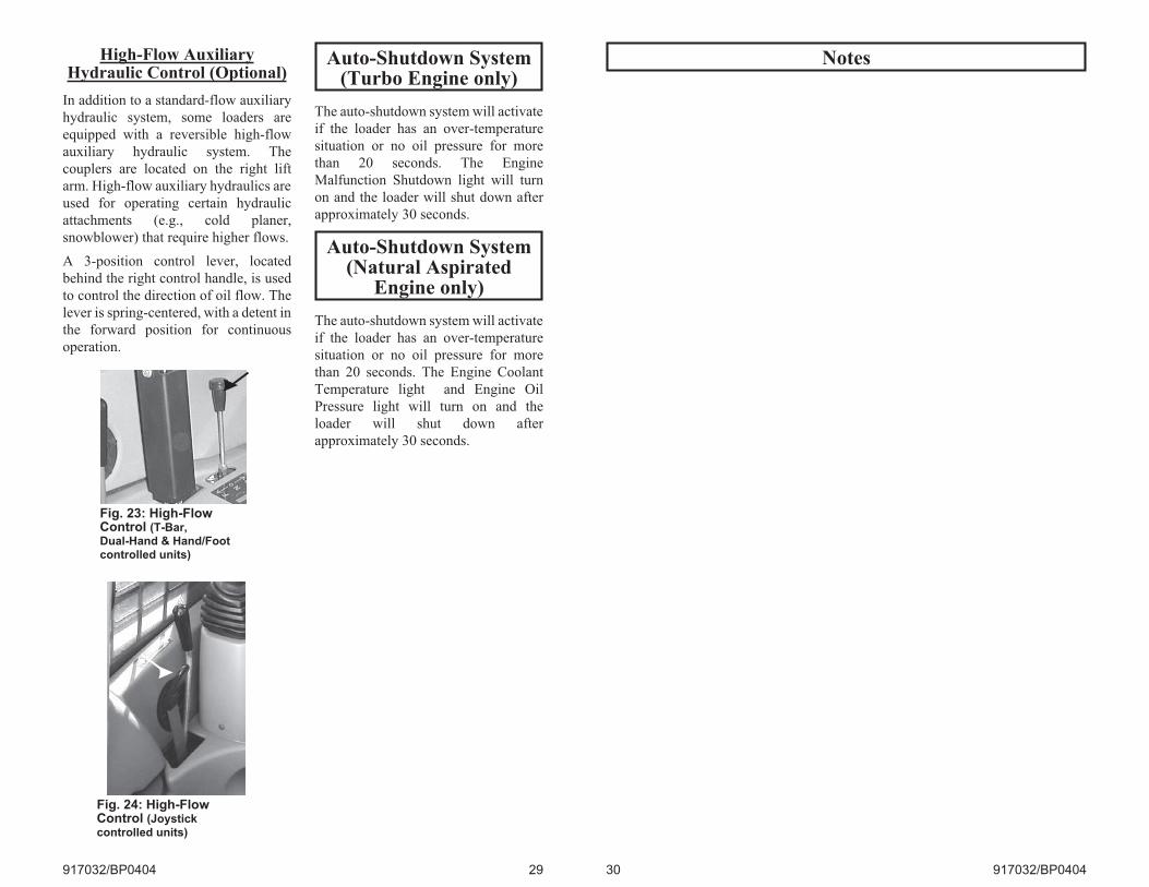
Auxiliary HydraulicControls
Auxiliary hydraulics are used with
attachments that have a mechanism
requiring its own hydraulic power.
Important: Always be sure the
auxiliary hydraulic control is in
neutral before starting the loader or
disconnecting the auxiliary hydraulic
couplers.
Standard Flow AuxiliaryHydraulic
Coupler hookup is located on the left lift
arm. “A” port is pressure, “B” port is
return when the auxiliary hydraulics
controls are in the detent position (refer
to page 34). The flow can be manually
adjusted from 2 - 29 gpm (7,6 - 110
L/min) by turning the flow control knob
(Fig. 19).
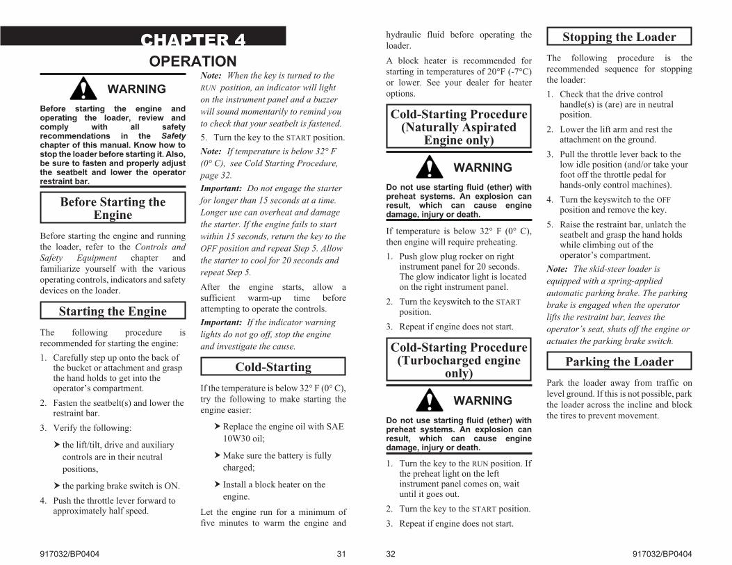
T-Bar, Dual-Hand and Joystick
Control Loaders: A foot pedal is used to
control the direction of oil flow. A latch
is provided to lock the foot pedal for
continuous operation (Fig. 21).
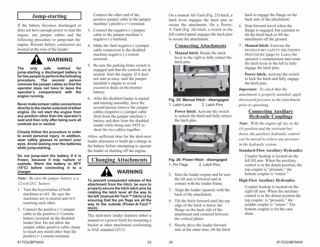
Hand/Foot Control Loaders: The right
handle controls the direction of oil flow.
A locking pin locks it in the up position
for continuous operation (Fig. 22).
28 917032/BP0404
Fig. 18: Auxiliary Couplers
1. High-Flow Couplers2. Standard-Flow Couplers
21
Fig. 19: Standard-FlowControl Knob (T-Bar,Dual-Hand & Hand/Footcontrolled units)
Fig. 20: Standard-FlowControl Knob (Joystickcontrolled units)
Fig. 21: T-Bar, Dual-Hand andJoystick Auxiliary Hydraulic Control
Fig. 22: Hand/ FootAuxiliary Control
High-Flow AuxiliaryHydraulic Control (Optional)
In addition to a standard-flow auxiliary
hydraulic system, some loaders are
equipped with a reversible high-flow
auxiliary hydraulic system. The
couplers are located on the right lift
arm. High-flow auxiliary hydraulics are
used for operating certain hydraulic
attachments (e.g., cold planer,
snowblower) that require higher flows.
A 3-position control lever, located
behind the right control handle, is used
to control the direction of oil flow. The
lever is spring-centered, with a detent in
the forward position for continuous
operation.
Auto-Shutdown System(Turbo Engine only)
The auto-shutdown system will activate
if the loader has an over-temperature
situation or no oil pressure for more
than 20 seconds. The Engine
Malfunction Shutdown light will turn
on and the loader will shut down after
approximately 30 seconds.
Auto-Shutdown System(Natural Aspirated
Engine only)
The auto-shutdown system will activate
if the loader has an over-temperature
situation or no oil pressure for more
than 20 seconds. The Engine Coolant
Temperature light and Engine Oil
Pressure light will turn on and the
loader will shut down after
approximately 30 seconds.
917032/BP0404 29
Fig. 23: High-FlowControl (T-Bar,Dual-Hand & Hand/Footcontrolled units)
Fig. 24: High-FlowControl (Joystickcontrolled units)
Notes
30 917032/BP0404
CHAPTER 4
OPERATION
WARNING
Before starting the engine andoperating the loader, review andcomply with all safetyrecommendations in the Safetychapter of this manual. Know how tostop the loader before starting it. Also,be sure to fasten and properly adjustthe seatbelt and lower the operatorrestraint bar.
Before Starting theEngine
Before starting the engine and running
the loader, refer to the Controls and
Safety Equipment chapter and
familiarize yourself with the various
operating controls, indicators and safety
devices on the loader.
Starting the Engine
The following procedure is
recommended for starting the engine:
1. Carefully step up onto the back ofthe bucket or attachment and graspthe hand holds to get into theoperator’s compartment.
2. Fasten the seatbelt(s) and lower therestraint bar.
3. Verify the following:
� the lift/tilt, drive and auxiliary
controls are in their neutral
positions,
� the parking brake switch is ON.
4. Push the throttle lever forward toapproximately half speed.
Note: When the key is turned to the
RUN position, an indicator will light
on the instrument panel and a buzzer
will sound momentarily to remind you
to check that your seatbelt is fastened.
5. Turn the key to the START position.
Note: If temperature is below 32° F
(0° C), see Cold Starting Procedure,
page 32.
Important: Do not engage the starter
for longer than 15 seconds at a time.
Longer use can overheat and damage
the starter. If the engine fails to start
within 15 seconds, return the key to the
OFF position and repeat Step 5. Allow
the starter to cool for 20 seconds and
repeat Step 5.
After the engine starts, allow a
sufficient warm-up time before
attempting to operate the controls.
Important: If the indicator warning
lights do not go off, stop the engine
and investigate the cause.
Cold-Starting
If the temperature is below 32° F (0° C),
try the following to make starting the
engine easier:
� Replace the engine oil with SAE
10W30 oil;
�Make sure the battery is fully
charged;
� Install a block heater on the
engine.
Let the engine run for a minimum of
five minutes to warm the engine and
917032/BP0404 31
hydraulic fluid before operating the
loader.
A block heater is recommended for
starting in temperatures of 20°F (-7°C)
or lower. See your dealer for heater
options.
Cold-Starting Procedure(Naturally Aspirated
Engine only)
WARNING
Do not use starting fluid (ether) withpreheat systems. An explosion canresult, which can cause enginedamage, injury or death.
If temperature is below 32° F (0° C),
then engine will require preheating.
1. Push glow plug rocker on rightinstrument panel for 20 seconds.The glow indicator light is locatedon the right instrument panel.
2. Turn the keyswitch to the START
position.
3. Repeat if engine does not start.
Cold-Starting Procedure(Turbocharged engine
only)
WARNING
Do not use starting fluid (ether) withpreheat systems. An explosion canresult, which can cause enginedamage, injury or death.
1. Turn the key to the RUN position. Ifthe preheat light on the leftinstrument panel comes on, waituntil it goes out.
2. Turn the key to the START position.
3. Repeat if engine does not start.
Stopping the Loader
The following procedure is the
recommended sequence for stopping
the loader:
1. Check that the drive controlhandle(s) is (are) are in neutralposition.
2. Lower the lift arm and rest theattachment on the ground.
3. Pull the throttle lever back to thelow idle position (and/or take yourfoot off the throttle pedal forhands-only control machines).
4. Turn the keyswitch to the OFF
position and remove the key.
5. Raise the restraint bar, unlatch theseatbelt and grasp the hand holdswhile climbing out of theoperator’s compartment.
Note: The skid-steer loader is
equipped with a spring-applied
automatic parking brake. The parking
brake is engaged when the operator
lifts the restraint bar, leaves the
operator’s seat, shuts off the engine or
actuates the parking brake switch.
Parking the Loader
Park the loader away from traffic on
level ground. If this is not possible, park
the loader across the incline and block
the tires to prevent movement.
32 917032/BP0404
Jump-starting
If the battery becomes discharged or
does not have enough power to start the
engine, use jumper cables and the
following procedure to jump-start the
engine. Remote battery connectors are
located at the rear of the loader.
WARNING
The only safe method forjump-starting a discharged battery isfor two people to perform the followingprocedure. The second personremoves the jumper cables so that theoperator does not have to leave theoperator’s compartment with theengine running.
Never make jumper cable connectionsdirectly to the starter solenoid of eitherengine. Do not start the engine fromany position other than the operator’sseat and then only after being sure allcontrols are in neutral.
Closely follow the procedure in orderto avoid personal injury. In addition,wear safety glasses to protect youreyes. Avoid leaning over the batterieswhile jump-starting.
Do not jump-start the battery if it isfrozen, because it may rupture orexplode. Warm the battery to 60°F(16°C) before connecting it to acharger.
Note: Be sure the jumper battery is a
12-volt D.C. battery.
1. Turn the keyswitches of bothmachines to OFF. Be sure themachines are in neutral and NOT
touching each other.
2. Connect the positive (+) jumpercable to the positive (+) remotebattery terminal on the disabledloader first. Do not allow thejumper cables positive cable clampto touch any metal other than thepositive (+) remote terminal.
Connect the other end of thepositive jumper cable to the jumpermachine’s positive (+) terminal.
3. Connect the negative (-) jumpercable to the jumper machine’snegative (-) terminal.
4. Make the final negative (-) jumpercable connection to the disabledmachine negative (-) remoteterminal.
5. Be sure the parking brake switch isengaged and that the controls are inneutral. Start the engine. If it doesnot start at once, start the jumpermachine’s engine to avoidexcessive drain on the boosterbattery.
6. After the disabled loader is startedand running smoothly, have thesecond person remove the jumpercables (negative (-) jumper cablefirst) from the jumper machine’sbattery and then from the disabledloader while being sure NOT toshort the two cables together.
Allow sufficient time for the skid-steer
loader alternator to build up a charge in
the battery before attempting to operate
the loader or shutting off the engine.
Changing Attachments
WARNING
To prevent unexpected release of theattachment from the hitch, be sure toproperly secure the hitch latch pins byrotating the latch lever all the way tothe left (manual All-Tach™ hitch) or byensuring that the pin flags are all theway to the outside (Power-A-Tach™hitch).
The skid-steer loader features either a
manual or a power hitch for mounting a
bucket or other attachment conforming
to SAE standard J2513.
917032/BP0404 33
On a manual All-Tach (Fig. 25) hitch, a
latch lever engages the latch pins to
secure the attachment. On a Power-
A-Tach (Fig. 26) hitch, a switch on the
left control panel engages the latch pins
to secure the attachment.
Connecting Attachments
1. Manual hitch: Rotate the latchlever to the right to fully retract thelatch pins.
Power hitch: Activate the switchto unlock the hitch and fully retractthe latch pins.
2. Start the loader engine and be surethe lift arm is lowered and incontact with the loader frame.
3. Align the loader squarely with theback of the attachment.
4. Tilt the hitch forward until the topedge of the hitch is below theflange on the back side of theattachment and centered betweenthe vertical plates.
5. Slowly drive the loader forwardand, at the same time, tilt the hitch
back to engage the flange on theback side of the attachment.
6. Stop forward travel when theflange is engaged, but continue totilt the hitch back to lift theattachment off the ground.
7. Manual hitch: Exercise theMANDATORY SAFETY SHUTDOWN
PROCEDURE (page 6). Leave theoperator’s compartment and rotatethe latch lever to the left to fullyengage the latch pins.
Power hitch: Activate the switchto lock the hitch and fully engagethe latch pins.
Important: To check that the
attachment is properly installed, apply
downward pressure to the attachment
prior to operating.
Connecting AuxiliaryHydraulic Couplings
Note: With the engine off, key in the
ON position and the restraint bar
down, the auxiliary hydraulic control
can be moved to relieve any pressure
in the hydraulic system.
Standard-Flow Auxiliary Hydraulics
Coupler hookup is located on theleft lift arm. When the auxiliarycontrol is in the detent position, thetop coupler is “pressure,” thebottom coupler is “return.”
High-Flow Auxiliary Hydraulics
Coupler hookup is located on theright lift arm. When the auxiliarycontrol is in the detent position thetop coupler is “pressure,” themiddle coupler is “return.” Thebottom coupler is for the casedrain.
34 917032/BP0404
Fig. 25: Manual Hitch - disengaged
1. Latch Lever 2. Latch Pins
Fig. 26: Power Hitch - disengaged
1. Pin Flags 2. Latch Pins
1 1
22
2 2
1
WARNING
Only attempt to connect high-flowattachment couplers to the high-flowauxiliary couplers.
Removing Attachments
1. Tilt the hitch back until theattachment is off the ground.
2. Exercise the MANDATORY SAFETY
SHUTDOWN PROCEDURE (page 6).
3. Relieve any hydraulic pressure inthe auxiliary and attachment lines.
a. Turn the key ON (do not start
the engine).
b. With the restraint bar down,
move the auxiliary hydraulic
control back and forth. This will
relieve the pressure in the
hydraulic system.
4. With the engine off, leave theoperator’s compartment anddisconnect the auxiliary hydraulichoses.
5. Manual hitch: Rotate the hitchlatch lever to the right to fullyretract the latch pins.
Power hitch: Turn the key ON (donot start the engine) and activatethe switch to unlock the hitch andfully retract the latch pins.
6. Start the engine and be sure that thelift arm is fully lowered and incontact with the loader frame.
7. Tilt the hitch forward and slowlyback the loader away until theattachment is free from the loader.
Self-Leveling
The feature is designed to automatically
keep the attachment level while the lift
arm is being raised.
Using a Bucket
WARNING
Always maintain a safe distance fromelectric power lines and avoid contactwith any electrically chargedconductor or gas line. Accidentalcontact or rupture can result inelectrocution or an explosion. Contactthe “Digger’s Hotline” or proper localauthorities for utility line locationsbefore starting to dig.
Driving over Rough Terrain
When traveling over rough terrain,
drive slowly with the bucket lowered.
Driving on an Incline
When traveling on an incline, travel
with the heavy end pointing uphill.
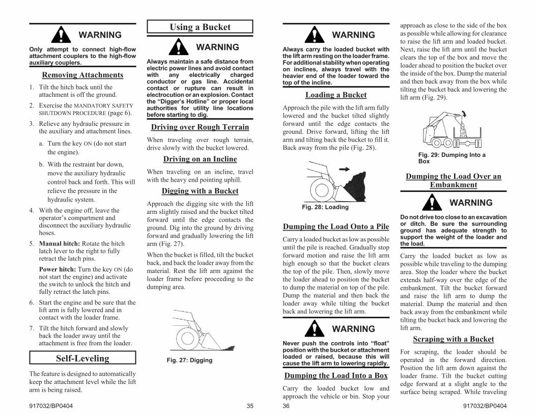
Digging with a Bucket
Approach the digging site with the lift
arm slightly raised and the bucket tilted
forward until the edge contacts the
ground. Dig into the ground by driving
forward and gradually lowering the lift
arm (Fig. 27).
When the bucket is filled, tilt the bucket
back, and back the loader away from the
material. Rest the lift arm against the
loader frame before proceeding to the
dumping area.
917032/BP0404 35
Fig. 27: Digging
WARNING
Always carry the loaded bucket withthe lift arm resting on the loader frame.For additional stability when operatingon inclines, always travel with theheavier end of the loader toward thetop of the incline.
Loading a Bucket
Approach the pile with the lift arm fully
lowered and the bucket tilted slightly
forward until the edge contacts the
ground. Drive forward, lifting the lift
arm and tilting back the bucket to fill it.
Back away from the pile (Fig. 28).
Dumping the Load Onto a Pile
Carry a loaded bucket as low as possible
until the pile is reached. Gradually stop
forward motion and raise the lift arm
high enough so that the bucket clears
the top of the pile. Then, slowly move
the loader ahead to position the bucket
to dump the material on top of the pile.
Dump the material and then back the
loader away while tilting the bucket
back and lowering the lift arm.
WARNING
Never push the controls into “float”position with the bucket or attachmentloaded or raised, because this willcause the lift arm to lowering rapidly.
Dumping the Load Into a Box
Carry the loaded bucket low and
approach the vehicle or bin. Stop your
approach as close to the side of the box
as possible while allowing for clearance
to raise the lift arm and loaded bucket.
Next, raise the lift arm until the bucket
clears the top of the box and move the
loader ahead to position the bucket over
the inside of the box. Dump the material
and then back away from the box while
tilting the bucket back and lowering the
lift arm (Fig. 29).
Dumping the Load Over anEmbankment
WARNING
Do not drive too close to an excavationor ditch. Be sure the surroundingground has adequate strength tosupport the weight of the loader andthe load.
Carry the loaded bucket as low as
possible while traveling to the dumping
area. Stop the loader where the bucket
extends half-way over the edge of the
embankment. Tilt the bucket forward
and raise the lift arm to dump the
material. Dump the material and then
back away from the embankment while
tilting the bucket back and lowering the
lift arm.
Scraping with a Bucket
For scraping, the loader should be
operated in the forward direction.
Position the lift arm down against the
loader frame. Tilt the bucket cutting
edge forward at a slight angle to the
surface being scraped. While traveling
36 917032/BP0404
Fig. 28: Loading
Fig. 29: Dumping Into aBox
slowly forward with the bucket in this
position, material can flow over the
cutting edge and collect inside the
bucket (Fig. 30).
Leveling the Ground
Drive the loader to the far edge of the
area to be leveled. Tilt the bucket
forward to place the bucket cutting edge
at a 30 to 45 degree angle to the surface
being leveled. Then place the lift arm
into the float position and drive the
loader rearward, dragging the dirt and,
at the same time, leveling it (Fig. 31).
Note: The detent (“float”) position
for T-bar loaders is reached by
pushing the right handle all the way
forward, and for dual-hand control
loaders by rotating the left handle all
the way outward. For hand/foot
control loaders, use the toes of the left
foot to push the front of the left pedal
all the way down. For joystick control
loaders press float button on the right
grip. Pressing button for more than 5
seconds will allow the machine to go
into detent (“float”) mode. Press
again to cancel detent.
WARNING
Check that the work area is clear ofpeople and obstacles. Always look inthe direction of travel.
Highway Travel
If it becomes necessary to move the
loader a long distance, use a properly
rated trailer. (See “Transporting the
Loader,” page 37) For short distance
highway travel, attach an SMV (Slow
Moving Vehicle) emblem (purchased
locally) to the back of the loader. For
highway operation, install dual amber
flashers or a strobe light. Check state
and local laws and regulations.
Storing the Loader
If your skid-steer loader is to be stored
for a long period of time, the following
procedure is suggested:
1. Fully inflate the tires.
2. Lubricate all grease zerks.
3. Check all fluid levels and replenishas necessary.
4. Add stabilizer to the fuel per thefuel supplier’s recommendations.
5. Remove the battery, charge fullyand store in a cool, dry location.
6. Protect against extreme weatherconditions such as moisture,sunlight and temperature.
917032/BP0404 37
Fig. 30: Scraping
Fig. 31: Leveling theGround
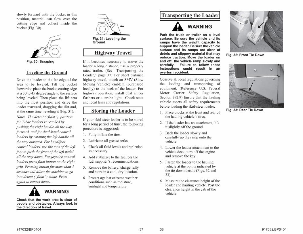
Transporting the Loader
WARNING
Park the truck or trailer on a levelsurface. Be sure the vehicle and itsramps have the weight capacity tosupport the loader. Be sure the vehiclesurface and its ramps are clear ofdebris and slippery material that mayreduce traction. Move the loader onand off the vehicle ramp slowly andcarefully. Failure to follow theseinstructions could result in anoverturn accident.
Observe all local regulations governing
the loading and transporting of
equipment. (Reference U.S. Federal
Motor Carrier Safety Regulation,
Section 392.9) Ensure that the hauling
vehicle meets all safety requirements
before loading the skid-steer loader.
1. Place blocks at the front and rear ofthe hauling vehicle’s tires.
2. If the loader has an attachment, liftit slightly off the ground.
3. Back the loader slowly andcarefully up the ramp onto thevehicle.
4. Lower the loader attachment to thevehicle deck, turn off the engineand remove the key.
5. Fasten the loader to the haulingvehicle at the points indicated bythe tie-down decals (Figs. 32 and33).
6. Measure the clearance height of theloader and hauling vehicle. Post theclearance height in the cab of thevehicle.
38 917032/BP0404
Fig. 32: Front Tie Down
Fig. 33: Rear Tie Down
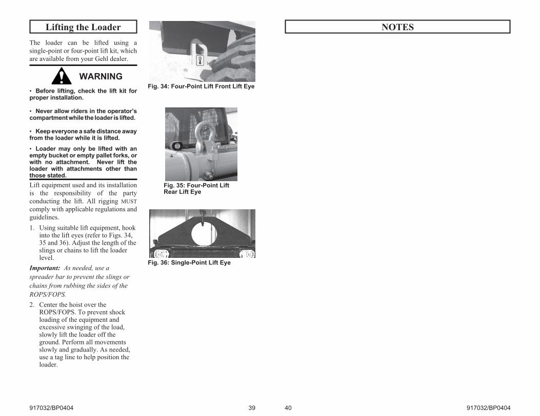
Lifting the Loader
The loader can be lifted using a
single-point or four-point lift kit, which
are available from your Gehl dealer.
WARNING
• Before lifting, check the lift kit forproper installation.
• Never allow riders in the operator’scompartment while the loader is lifted.
• Keep everyone a safe distance awayfrom the loader while it is lifted.
• Loader may only be lifted with anempty bucket or empty pallet forks, orwith no attachment. Never lift theloader with attachments other thanthose stated.
Lift equipment used and its installation
is the responsibility of the party
conducting the lift. All rigging MUST
comply with applicable regulations and
guidelines.
1. Using suitable lift equipment, hookinto the lift eyes (refer to Figs. 34,35 and 36). Adjust the length of theslings or chains to lift the loaderlevel.
Important: As needed, use a
spreader bar to prevent the slings or
chains from rubbing the sides of the
ROPS/FOPS.
2. Center the hoist over theROPS/FOPS. To prevent shockloading of the equipment andexcessive swinging of the load,slowly lift the loader off theground. Perform all movementsslowly and gradually. As needed,use a tag line to help position theloader.
917032/BP0404 39
Fig. 34: Four-Point Lift Front Lift Eye
Fig. 35: Four-Point LiftRear Lift Eye
Fig. 36: Single-Point Lift Eye
NOTES
40 917032/BP0404
CHAPTER 5
SERVICE
WARNING
Before servicing the machine, unlessexpressly instructed to the contrary,exercise the MANDATORY SAFETY
SHUTDOWN PROCEDURE (page 6).
After service has been performed, besure to restore all guards, shields andcovers to their original positionsbefore resuming operation.
This Service chapter details procedures
for performing routine maintenance
checks, adjustments and replacements.
Most procedures are referred to in the
Troubleshooting and Maintenance
Schedule chapters of this manual. Refer
to the Maintenance Interval Chart
(page 65) for service intervals. Refer to
the separate engine manual for
engine-related adjustments, lubrication
and service procedures.
Note: All service procedures, except
those described under the “Dealer
Services” topic are owner-operator
responsibilities.
Important: Always dispose of waste
lubricating oils and hydraulic fluids
according to local regulations or take
to a recycling center for disposal. Do
not pour onto the ground or down the
drain.
Dealer Services
The following areas of component
service, replacement and adjustments
require special tools and knowledge for
proper servicing and should be
performed only by your authorized
Gehl skid-steer loader dealer:
hydrostatic drive components,
hydraulic system pumps, valves,
hydraulic cylinders, electrical
components (other than battery, circuit
breakers).
917032/BP0404 41
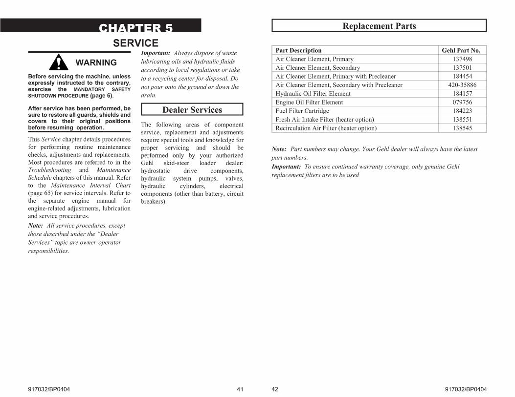
Replacement Parts
42 917032/BP0404
Part Description Gehl Part No.
Air Cleaner Element, Primary 137498
Air Cleaner Element, Secondary 137501
Air Cleaner Element, Primary with Precleaner 184454
Air Cleaner Element, Secondary with Precleaner 420-35886
Hydraulic Oil Filter Element 184157
Engine Oil Filter Element 079756
Fuel Filter Cartridge 184223
Fresh Air Intake Filter (heater option) 138551
Recirculation Air Filter (heater option) 138545
Note: Part numbers may change. Your Gehl dealer will always have the latest
part numbers.
Important: To ensure continued warranty coverage, only genuine Gehl
replacement filters are to be used
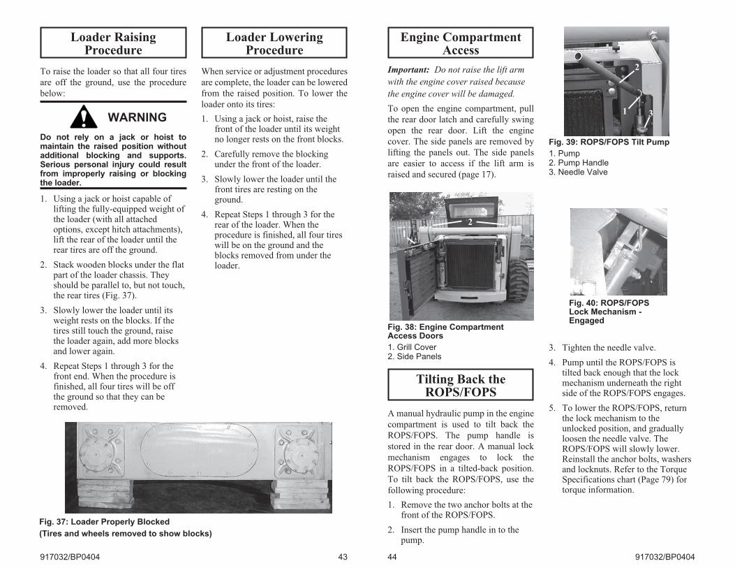
Loader RaisingProcedure
To raise the loader so that all four tires
are off the ground, use the procedure
below:
WARNING
Do not rely on a jack or hoist tomaintain the raised position withoutadditional blocking and supports.Serious personal injury could resultfrom improperly raising or blockingthe loader.
1. Using a jack or hoist capable oflifting the fully-equipped weight ofthe loader (with all attachedoptions, except hitch attachments),lift the rear of the loader until therear tires are off the ground.
2. Stack wooden blocks under the flatpart of the loader chassis. Theyshould be parallel to, but not touch,the rear tires (Fig. 37).
3. Slowly lower the loader until itsweight rests on the blocks. If thetires still touch the ground, raisethe loader again, add more blocksand lower again.
4. Repeat Steps 1 through 3 for thefront end. When the procedure isfinished, all four tires will be offthe ground so that they can beremoved.
Loader LoweringProcedure
When service or adjustment procedures
are complete, the loader can be lowered
from the raised position. To lower the
loader onto its tires:
1. Using a jack or hoist, raise thefront of the loader until its weightno longer rests on the front blocks.
2. Carefully remove the blockingunder the front of the loader.
3. Slowly lower the loader until thefront tires are resting on theground.
4. Repeat Steps 1 through 3 for therear of the loader. When theprocedure is finished, all four tireswill be on the ground and theblocks removed from under theloader.
917032/BP0404 43
Fig. 37: Loader Properly Blocked
(Tires and wheels removed to show blocks)
Engine CompartmentAccess
Important: Do not raise the lift arm
with the engine cover raised because
the engine cover will be damaged.
To open the engine compartment, pull
the rear door latch and carefully swing
open the rear door. Lift the engine
cover. The side panels are removed by
lifting the panels out. The side panels
are easier to access if the lift arm is
raised and secured (page 17).
Tilting Back theROPS/FOPS
A manual hydraulic pump in the engine
compartment is used to tilt back the
ROPS/FOPS. The pump handle is
stored in the rear door. A manual lock
mechanism engages to lock the
ROPS/FOPS in a tilted-back position.
To tilt back the ROPS/FOPS, use the
following procedure:
1. Remove the two anchor bolts at thefront of the ROPS/FOPS.
2. Insert the pump handle in to thepump.
3. Tighten the needle valve.
4. Pump until the ROPS/FOPS istilted back enough that the lockmechanism underneath the rightside of the ROPS/FOPS engages.
5. To lower the ROPS/FOPS, returnthe lock mechanism to theunlocked position, and graduallyloosen the needle valve. TheROPS/FOPS will slowly lower.Reinstall the anchor bolts, washersand locknuts. Refer to the TorqueSpecifications chart (Page 79) fortorque information.
44 917032/BP0404
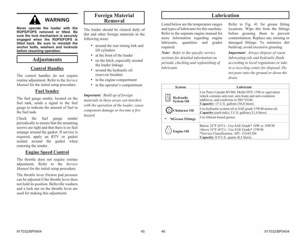
Fig. 38: Engine CompartmentAccess Doors
1. Grill Cover2. Side Panels
1
2
Fig. 39: ROPS/FOPS Tilt Pump
1. Pump2. Pump Handle3. Needle Valve
2
31
Fig. 40: ROPS/FOPSLock Mechanism -Engaged
WARNING
Never operate the loader with theROPS/FOPS removed or tilted. Besure the lock mechanism is securelyengaged when the ROPS/FOPS istilted back. Be sure to reinstall theanchor bolts, washers and locknutsbefore resuming operation.
Adjustments
Control Handles
The control handles do not require
routine adjustment. Refer to the Service
Manual for the initial setup procedure.
Fuel Sender
The fuel gauge sender, located on the
fuel tank, sends a signal to the fuel
gauge to indicate the amount of fuel in
the fuel tank.
Check the fuel gauge sender
periodically to ensure that the mounting
screws are tight and that there is no fuel
seepage around the gasket. If service is
required, apply an RTV or gasket
sealant around the gasket when
restoring the sender.
Engine Speed Control
The throttle does not require routine
adjustment. Refer to the Service
Manual for the initial setup procedure.
The throttle lever friction pad pressure
can be adjusted if the throttle lever does
not hold its position. Belleville washers
and a lock nut on the throttle lever are
used for making this adjustment.
Foreign MaterialRemoval
The loader should be cleared daily of
dirt and other foreign materials in the
following areas:
• around the rear timing link and
lift cylinders
• at the front of the loader
• on the hitch, especially around
the loader linkage
• around the hydraulic oil
reservoir breather
• in the engine compartment
• in the operator’s compartment
Important: Build up of foreign
materials in these areas can interfere
with the operation of the loader, cause
component damage or become a fire
hazard.
917032/BP0404 45
Lubrication
Listed below are the temperature ranges
and types of lubricants for this machine.
Refer to the separate engine manual for
more information regarding engine
lubricants, quantities and grades
required.
Note: Refer to the specific service
sections for detailed information on
periodic checking and replenishing of
lubricants.
Refer to Fig. 41 for grease fitting
locations. Wipe dirt from the fittings
before greasing them to prevent
contamination. Replace any missing or
damaged fittings. To minimize dirt
build-up, avoid excessive greasing.
Important: Always dispose of waste
lubricating oils and hydraulic fluids
according to local regulations or take
to a recycling center for disposal. Do
not pour onto the ground or down the
drain.
46 917032/BP0404
System Lubricant
HydraulicSystem Oil
Use Petro Canada HVI60, Mobil DTE 15M or equivalentwhich contains anti-rust, anti-foam and anti-oxidationadditives, and conforms to ISO VG46.Capacity: 15 U.S. gallons (56,8 liters)
Chaincase OilUse hydraulic system oil or SAE grade 15W40 motor oil.Capacity (each side): 3 U.S. gallons (11,4 liters)
Grease FittingsUse lithium-based grease.
Engine Oil
Below 32°F (0°C) - Use SAE Grade* 10W or 10W30Above 32°F (0°C) - Use SAE Grade* 15W40*Service Classification: API - CG4/CH4Capacity: 8.9 U.S. quarts (8,5 liters)
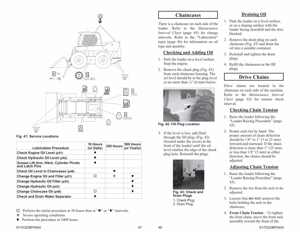
917032/BP0404 47
Fig. 41: Service Locations
Lubrication Procedure10 Hours(or Daily)
250 Hours500 Hours(or Yearly)
Check Engine Oil Level (p51) �
Check Hydraulic Oil Level (p52) �
Grease Lift Arm, Hitch, Cylinder Pivotsand Latch Pins
�
Check Oil Level in Chaincases (p48) �
Change Engine Oil and Filter (p51) � � �
Change Hydraulic Oil Filter (p53) �
Change Hydraulic Oil (p53) �
Change Chaincase Oil (p48) � �
Check and Drain Water Separator �
� Perform the initial procedure at 50 hours then at “�” or “�” intervals.
� Severe operating conditions.
� Perform the procedure at 1000 hours.
Chaincases
There is a chaincase on each side of the
loader. Refer to the Maintenance
Interval Chart (page 65) for change
intervals. Refer to the “Lubrication”
topic (page 46) for information on oil
type and quantity.
Checking and Adding Oil
1. Park the loader on a level surface.Stop the engine.
2. Remove the check plug (Fig. 43)from each chaincase housing. Theoil level should be at the plug levelor no more than ¼” (6 mm) below.
3. If the level is low, add fluidthrough the fill plug; (Fig. 42)(located under the covers at thefront of the loader) until the oillevel reaches the edge of the checkplug hole. Reinstall the plugs.
Draining Oil
1. Park the loader on a level surface,or on a sloping surface with theloader facing downhill and the tiresblocked.
2. Remove the drain plug on eachchaincase (Fig. 43) and drain theoil into a suitable container.
3. Reinstall and tighten the drainplugs.
4. Refill the chaincases at the fillplugs.
Drive Chains
Drive chains are located in the
chaincase on each side of the machine.
Refer to the Maintenance Interval
Chart (page 65) for tension check
interval.
Checking Chain Tension
1. Raise the loader following the“Loader Raising Procedure” (page43).
2. Rotate each tire by hand. Theproper amount of chain defectionshould be 1/8” to 1” (3 to 25 mm)forward and rearward. If the chaindefection is more than 1” (25 mm)or less than 1/8” (3 mm) in eitherdirection, the chains should beadjusted.
Adjusting Chain Tension
1. Raise the loader following the“Loader Raising Procedure” (page43).
2. Remove the tire from the axle to beadjusted.
3. Loosen (but DO NOT remove) thebolts holding the axle to thechaincase.
4. Front Chain Tension – To tightenthe front chain, move the front axleassembly toward the front of the
48 917032/BP0404
Fig. 42: Fill Plug Location
Fig. 43: Check andDrain Plugs
1. Check Plug2. Drain Plug
12
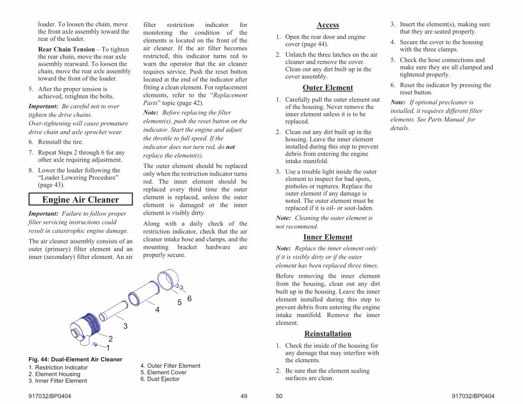
loader. To loosen the chain, movethe front axle assembly toward therear of the loader.
Rear Chain Tension – To tightenthe rear chain, move the rear axleassembly rearward. To loosen thechain, move the rear axle assemblytoward the front of the loader.
5. After the proper tension isachieved, retighten the bolts.
Important: Be careful not to over
tighten the drive chains.
Over-tightening will cause premature
drive chain and axle sprocket wear.
6. Reinstall the tire.
7. Repeat Steps 2 through 6 for anyother axle requiring adjustment.
8. Lower the loader following the“Loader Lowering Procedure”(page 43).
Engine Air Cleaner
Important: Failure to follow proper
filter servicing instructions could
result in catastrophic engine damage.
The air cleaner assembly consists of an
outer (primary) filter element and an
inner (secondary) filter element. An air
filter restriction indicator for
monitoring the condition of the
elements is located on the front of the
air cleaner. If the air filter becomes
restricted, this indicator turns red to
warn the operator that the air cleaner
requires service. Push the reset button
located at the end of the indicator after
fitting a clean element. For replacement
elements, refer to the “Replacement
Parts” topic (page 42).
Note: Before replacing the filter
element(s), push the reset button on the
indicator. Start the engine and adjust
the throttle to full speed. If the
indicator does not turn red, do not
replace the element(s).
The outer element should be replaced
only when the restriction indicator turns
red. The inner element should be
replaced every third time the outer
element is replaced, unless the outer
element is damaged or the inner
element is visibly dirty.
Along with a daily check of the
restriction indicator, check that the air
cleaner intake hose and clamps, and the
mounting bracket hardware are
properly secure.
917032/BP0404 49
Fig. 44: Dual-Element Air Cleaner
1. Restriction Indicator2. Element Housing3. Inner Filter Element
4. Outer Filter Element5. Element Cover6. Dust Ejector
2
3
45
6
1
Access
1. Open the rear door and enginecover (page 44).
2. Unlatch the three latches on the aircleaner and remove the cover.Clean out any dirt built up in thecover assembly.
Outer Element
1. Carefully pull the outer element outof the housing. Never remove theinner element unless it is to bereplaced.
2. Clean out any dirt built up in thehousing. Leave the inner elementinstalled during this step to preventdebris from entering the engineintake manifold.
3. Use a trouble light inside the outerelement to inspect for bad spots,pinholes or ruptures. Replace theouter element if any damage isnoted. The outer element must bereplaced if it is oil- or soot-laden.
Note: Cleaning the outer element is
not recommend.
Inner Element
Note: Replace the inner element only
if it is visibly dirty or if the outer
element has been replaced three times.
Before removing the inner element
from the housing, clean out any dirt
built up in the housing. Leave the inner
element installed during this step to
prevent debris from entering the engine
intake manifold. Remove the inner
element.
Reinstallation
1. Check the inside of the housing forany damage that may interfere withthe elements.
2. Be sure that the element sealingsurfaces are clean.
3. Insert the element(s), making surethat they are seated properly.
4. Secure the cover to the housingwith the three clamps.
5. Check the hose connections andmake sure they are all clamped andtightened properly.
6. Reset the indicator by pressing thereset button.
Note: If optional precleaner is
installed, it requires different filter
elements. See Parts Manual for
details.
50 917032/BP0404
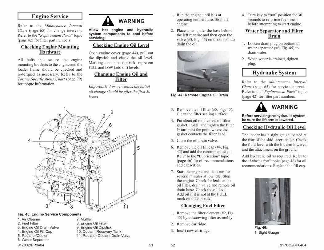
Engine Service
Refer to the Maintenance Interval
Chart (page 65) for change intervals.
Refer to the “Replacement Parts” topic
(page 42) for filter part numbers.
Checking Engine MountingHardware
All bolts that secure the engine
mounting brackets to the engine and the
loader frame should be checked and
re-torqued as necessary. Refer to the
Torque Specifications Chart (page 79)
for torque information.
WARNING
Allow hot engine and hydraulicsystem components to cool beforeservicing.
Checking Engine Oil Level
Open engine cover (page 44), pull out
the dipstick and check the oil level.
Markings on the dipstick represent
FULL and LOW (add oil) levels.
Changing Engine Oil andFilter
Important: For new units, the initial
oil change should be after the first 50
hours.
917032/BP0404 51
Fig. 45: Engine Service Components
1. Air Cleaner 7. Muffler2. Fuel Filter 8. Engine Oil Filter3. Engine Oil Drain Valve 9. Engine Oil Dipstick4. Engine Oil Fill Cap 10. Coolant Recovery Tank5. Radiator/Cooler 11. Radiator Coolant Drain Valve6. Water Separator
7
1
8
10
3
5
11
4
2
6
9
1. Run the engine until it is atoperating temperature. Stop theengine.
2. Place a pan under the hose behindthe left rear tire and then open thevalve (#3, Fig. 45) on the oil pan todrain the oil.
3. Remove the oil filter (#8, Fig. 45).Clean the filter sealing surface.
4. Put clean oil on the new oil filtergasket. Install and tighten the filter½ turn past the point where thegasket contacts the filter head.
5. Close the oil drain valve.
6. Remove the oil fill cap (#4, Fig.45) and add the recommended oil.Refer to the “Lubrication” topic(page 46) for oil recommendationsand capacities.
7. Start the engine and let it run forseveral minutes at low idle. Stopthe engine. Check for leaks at theoil filter, drain valve and remote oildrain hose. Check the oil level.Add oil if it is not at the FULLmark on the dipstick.
Changing Fuel Filter
1. Remove the filter element (#2, Fig.45) by unscrewing filter assembly.
2. Remove cartridge.
3. Insert new cartridge.
4. Turn key to “run” position for 30seconds to re-prime fuel linesbefore attempting to start engine.
Water Separator and FilterDrain
1. Loosen drain plug on bottom ofwater separator (#6, Fig. 45) todrain water.
2. When water is drained, tightenplug.
Hydraulic System
Refer to the Maintenance Interval
Chart (page 65) for service intervals.
Refer to the “Replacement Parts” topic
(page 42) for filter part numbers.
WARNING
Before servicing the hydraulic system,be sure the lift arm is lowered.
Checking Hydraulic Oil Level
The loader has a sight gauge located at
the rear of the skid-steer loader. Check
the fluid level with the lift arm lowered
and the attachment on the ground.
Add hydraulic oil as required. Refer to
the “Lubrication” topic (page 46) for oil
recommendations. Replace the fill cap.
52 917032/BP0404
Fig. 46:
1. Sight Gauge
Fig. 47: Remote Engine Oil Drain
1
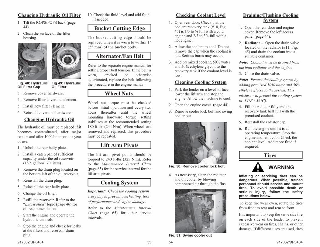
Changing Hydraulic Oil Filter
1. Tilt the ROPS/FOPS back (page44).
2. Clean the surface of the filterhousing.
3. Remove cover hardware.
4. Remove filter cover and element.
5. Install new filter element.
6. Reinstall cover and hardware.
Changing Hydraulic Oil
The hydraulic oil must be replaced if it
becomes contaminated, after major
repairs and after 1000 hours or one year
of use.
1. Unbolt the rear belly plate.
2. Install a catch pan of sufficientcapacity under the oil reservoir(18.5 gallons; 70 liters).
3. Remove the drain plug located onthe bottom left of the oil reservoir.
4. Reinstall the drain plug.
5. Reinstall the rear belly plate.
6. Change the oil filter.
7. Refill the reservoir. Refer to the“Lubrication” topic (page 46) foroil recommendations.
8. Start the engine and operate thehydraulic controls.
9. Stop the engine and check for leaksat the filters and reservoir drainplug.
10. Check the fluid level and add fluidif needed.
Bucket Cutting Edge
The bucket cutting edge should be
replaced when it is worn to within 1"
(25 mm) of the bucket body.
Alternator/Fan Belt
Refer to the separate engine manual for
setting proper belt tension. If the belt is
worn, cracked or otherwise
deteriorated, replace the belt following
the procedure in the engine manual.
Wheel Nuts
Wheel nut torque must be checked
before initial operation and every two
hours thereafter until the wheel
mounting hardware torque setting
stabilizes at the recommended setting
180 ft-lbs (244 N·m). When wheels are
removed and replaced, this procedure
must be repeated.
Lift Arm Pivots
The lift arm pivot points should be
torqued to 240 ft-lbs (325 N·m). Refer
to the Maintenance Interval Chart
(page 65) for the service interval for the
lift arm pivots.
Cooling System
Important: Check the cooling system
every day to prevent overheating, loss
of performance and engine damage.
Refer to the Maintenance Interval
Chart (page 65) for other service
intervals.
917032/BP0404 53
Fig. 48: HydraulicOil Filter Cap
Fig 49: HydraulicOil Filter
Checking Coolant Level
1. Open rear door. Check that thecoolant recovery tank (#10, Fig.45) is 1/3 to ½ full with a coldengine and 2/3 to 3/4 full with ahot engine.
2. Allow the coolant to cool. Do notremove the cap when the coolant ishot. Serious burns may occur.
3. Add premixed coolant, 50% waterand 50% ethylene glycol, to therecovery tank if the coolant level islow.
Cleaning Cooling System
1. Park the loader on a level surface,lower the lift arm and stop theengine. Allow the machine to cool.
2. Open the engine cover (page 44).
3. Remove cooler lock bolt and swingcooler out.
4. As necessary, clean the radiatorand oil cooler by blowingcompressed air through the fins.
Draining/Flushing CoolingSystem
1. Open the rear door and enginecover. Remove the left accesspanel (page 44).
2. Radiator – Open the drain valvelocated on the radiator (#11, Fig.45) and drain the coolant into asuitable container.
Note: Coolant must be drained from
the both radiator and the engine.
3. Close the drain valve.
Note: Protect the cooling system by
adding premixed 50% water and 50%
ethylene glycol to the system. This
mixture will protect the cooling system
to -34°F (-36°C).
4. Fill the radiator fully and therecovery tank half full with thepremixed coolant.
5. Reinstall the radiator cap.
6. Run the engine until it is atoperating temperature. Stop theengine and let it cool. Check thecoolant level. Add more fluid ifrequired.
Tires
WARNING
Inflating or servicing tires can bedangerous. When possible, trainedpersonnel should service and mounttires. To avoid possible death orserious injury, follow the safetyprecautions below.
To keep tire wear even, rotate the tires
from front to rear and rear to front.
It is important to keep the same size tire
on each side of the loader to prevent
excessive wear on tires, chains, or other
damage. If different sizes are used, tires
54 917032/BP0404
Fig. 50: Remove cooler lock bolt
Fig. 51: Swing cooler out
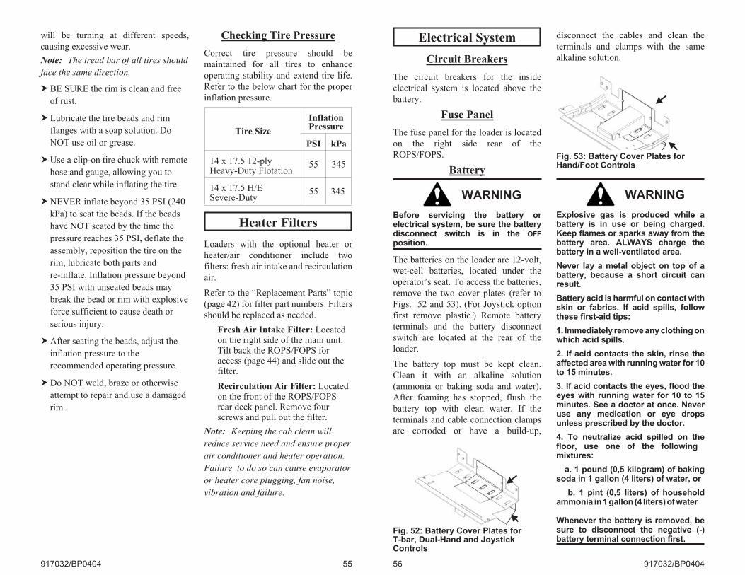
will be turning at different speeds,
causing excessive wear.
Note: The tread bar of all tires should
face the same direction.
� BE SURE the rim is clean and free
of rust.
� Lubricate the tire beads and rim
flanges with a soap solution. Do
NOT use oil or grease.
�Use a clip-on tire chuck with remote
hose and gauge, allowing you to
stand clear while inflating the tire.
�NEVER inflate beyond 35 PSI (240
kPa) to seat the beads. If the beads
have NOT seated by the time the
pressure reaches 35 PSI, deflate the
assembly, reposition the tire on the
rim, lubricate both parts and
re-inflate. Inflation pressure beyond
35 PSI with unseated beads may
break the bead or rim with explosive
force sufficient to cause death or
serious injury.
�After seating the beads, adjust the
inflation pressure to the
recommended operating pressure.
�Do NOT weld, braze or otherwise
attempt to repair and use a damaged
rim.
Checking Tire Pressure
Correct tire pressure should be
maintained for all tires to enhance
operating stability and extend tire life.
Refer to the below chart for the proper
inflation pressure.
Heater Filters
Loaders with the optional heater or
heater/air conditioner include two
filters: fresh air intake and recirculation
air.
Refer to the “Replacement Parts” topic
(page 42) for filter part numbers. Filters
should be replaced as needed.
Fresh Air Intake Filter: Locatedon the right side of the main unit.Tilt back the ROPS/FOPS foraccess (page 44) and slide out thefilter.
Recirculation Air Filter: Locatedon the front of the ROPS/FOPSrear deck panel. Remove fourscrews and pull out the filter.
Note: Keeping the cab clean will
reduce service need and ensure proper
air conditioner and heater operation.
Failure to do so can cause evaporator
or heater core plugging, fan noise,
vibration and failure.
917032/BP0404 55
Tire Size
InflationPressure
PSI kPa
14 x 17.5 12-plyHeavy-Duty Flotation
55 345
14 x 17.5 H/ESevere-Duty
55 345
Electrical System
Circuit Breakers
The circuit breakers for the inside
electrical system is located above the
battery.
Fuse Panel
The fuse panel for the loader is located
on the right side rear of the
ROPS/FOPS.
Battery
WARNING
Before servicing the battery orelectrical system, be sure the batterydisconnect switch is in the OFF
position.
The batteries on the loader are 12-volt,
wet-cell batteries, located under the
operator’s seat. To access the batteries,
remove the two cover plates (refer to
Figs. 52 and 53). (For Joystick option
first remove plastic.) Remote battery
terminals and the battery disconnect
switch are located at the rear of the
loader.
The battery top must be kept clean.
Clean it with an alkaline solution
(ammonia or baking soda and water).
After foaming has stopped, flush the
battery top with clean water. If the
terminals and cable connection clamps
are corroded or have a build-up,
disconnect the cables and clean the
terminals and clamps with the same
alkaline solution.
WARNING
Explosive gas is produced while abattery is in use or being charged.Keep flames or sparks away from thebattery area. ALWAYS charge thebattery in a well-ventilated area.
Never lay a metal object on top of abattery, because a short circuit canresult.
Battery acid is harmful on contact withskin or fabrics. If acid spills, followthese first-aid tips:
1. Immediately remove any clothing onwhich acid spills.
2. If acid contacts the skin, rinse theaffected area with running water for 10to 15 minutes.
3. If acid contacts the eyes, flood theeyes with running water for 10 to 15minutes. See a doctor at once. Neveruse any medication or eye dropsunless prescribed by the doctor.
4. To neutralize acid spilled on thefloor, use one of the followingmixtures:
a. 1 pound (0,5 kilogram) of bakingsoda in 1 gallon (4 liters) of water, or
b. 1 pint (0,5 liters) of householdammonia in 1 gallon (4 liters) of water
Whenever the battery is removed, besure to disconnect the negative (-)battery terminal connection first.
56 917032/BP0404
Fig. 52: Battery Cover Plates forT-bar, Dual-Hand and JoystickControls
Fig. 53: Battery Cover Plates forHand/Foot Controls

CHAPTER 6
TROUBLESHOOTING
Electrical System
917032/BP0404 57
Problem Possible Cause Remedy
Entire electricalsystem does notfunction.
Battery disconnect switch isOFF position.
Turn battery disconnect switch toON.
Circuit breakers abovebattery have tripped ormalfunctioned.
Check circuit and locate problemcausing breaker to trip (breakersreset automatically).
Main wiring harnessconnectors at rear ofROPS/FOPS not properlyplugged in.
Check main harness connectors.
Battery terminals or cablesloose or corroded.
Clean battery terminals and cablesand retighten them.
Power cable from battery tocircuit breaker buss bar is notconnected.
Check power cable connection.
Battery is faulty. Test battery, replace as needed.
No instrument panellamps withkeyswitch turned to“ON”.
Gauge fuse is blown. Check circuit, install new fuse.
Battery terminals or cablesare loose or corroded.
Clean battery terminals and cablesand retighten them.
Fuel gauge does notwork.
Faulty fuel gauge sender. Replace fuel gauge sender.
Faulty fuel gauge. Replace fuel gauge.
Gauge fuse is blown. Check circuit, install new fuse.
Loose wiring/terminalconnections.
Verify wiring connections.
Engine temperaturegauge does notwork.
Faulty temperature sender. Replace temperature sender.
Gauge fuse is blown. Check circuit, install new fuse.
Faulty temperature gauge. Replace temperature gauge.
Loose wiring/terminalconnections.
Verify wiring connections.
Hourmeter does notwork.
Loose wiring/terminalconnections.
Verify wiring connections.
Faulty alternator. Repair alternator.
Faulty hourmeter. Replace hourmeter.
Electrical System
58 917032/BP0404
Problem Possible Cause Remedy
Starter will notengage when key isturned to START.
Seat or restraint bar switchmalfunctioning or notactuated.
Contact your dealer.
Poor connections to starterrelay in instrument panel.
Verify relay connections.
Battery terminal or cablesloose or corroded.
Clean terminal, cables andretighten.
Faulty starter relay ininstrument panel.
Contact your dealer.
Battery discharged ordefective.
Recharge or replace battery.
Starter solenoid notfunctioning.
Contact your dealer.
Ignition wiring, seat switch,restraint bar switch, etc.loose or disconnected.
Check wiring for poor connections,broken leads; repair wiring orconnection.
Starter safety relaymalfunctioning.
Verify relay is working properly,replace.
Starter or pinion faulty. Remove starter; repair/replace asneeded.
Work lights notfunctioningproperly.
Single light not working;light bulb burned out, faultywiring.
Check and replace light bulb asneeded. Check wiring connection tolight.
No lights; 30 ampere lightfuse blown.
Check circuit and locate troublebefore replacing fuse.
Faulty light switch or poorground.
Check ground wire connections.Replace light switch.
Lift/Tilt and/ordrive lock solenoidsdo not work.
Wiring to solenoidsdisconnected or faulty.
Troubleshoot circuit, repair.
Restraint bar or seat switchmalfunction.
Contact your dealer.
Faulty solenoid valve coil. Contact your dealer.
Solenoid relaymalfunctioning.
Verify relay is working properly,replace.
Faulty hydraulic solenoidrelay in instrument panel.
Contact your dealer.
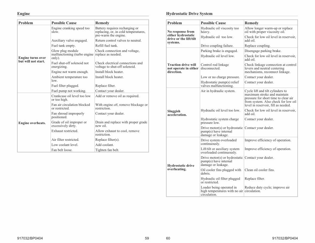
Engine
917032/BP0404 59
Problem Possible Cause Remedy
Engine turns overbut will not start.
Engine cranking speed tooslow.
Battery requires recharging orreplacing, or, in cold temperatures,pre-warm the engine.
Auxiliary valve engaged. Return control valves to neutral.
Fuel tank empty. Refill fuel tank.
Glow plug modulemalfunctioning (turbo engineonly).
Check connection and voltage,replace as needed.
Fuel shut-off solenoid notenergizing.
Check electrical connections andvoltage to shut-off solenoid.
Engine not warm enough. Install block heater.
Ambient temperature toolow.
Install block heater.
Fuel filter plugged. Replace filter.
Fuel pump not working. Contact your dealer.
Engine overheats.
Crankcase oil level too lowor too high.
Add or remove oil as required.
Fan air circulation blockedor restricted.
With engine off, remove blockage orrestriction.
Fan shroud improperlypositioned.
Contact your dealer.
Grade of oil improper orexcessively dirty.
Drain and replace with proper gradenew oil.
Exhaust restricted. Allow exhaust to cool, removerestriction.
Air filter restricted. Replace filter(s).
Low coolant level. Add coolant.
Fan belt loose. Tighten fan belt.
Hydrostatic Drive System
60 917032/BP0404
Problem Possible Cause Remedy
No response fromeither hydrostaticdrive or the lift/tiltsystems.
Hydraulic oil viscosity tooheavy.
Allow longer warm-up or replaceoil with proper viscosity oil.
Hydraulic oil too low. Check for low oil level in reservoir,add oil.
Drive coupling failure. Replace coupling.
Traction drive willnot operate in eitherdirection.
Parking brake is engaged. Disengage parking brake.
Hydraulic oil level low. Check for low oil level in reservoir,add oil.
Control rod linkagedisconnected.
Check linkage connection at controllevers and neutral centeringmechanisms, reconnect linkage.
Low or no charge pressure. Contact your dealer.
Hydrostatic pump(s) reliefvalves malfunctioning.
Contact your dealer.
Sluggishacceleration.
Air in hydraulic system. Cycle lift and tilt cylinders tomaximum stroke and maintainpressure for short time to clear airfrom system. Also check for low oillevel in reservoir, fill as needed.
Hydraulic oil level too low. Check for low oil level in reservoir,add oil.
Hydrostatic system chargepressure low.
Contact your dealer.
Drive motor(s) or hydrostaticpump(s) have internaldamage or leakage.
Contact your dealer.
Hydrostatic driveoverheating.
Drive system overloadedcontinuously.
Improve efficiency of operation.
Lift/tilt or auxiliary systemoverloaded continuously.
Improve efficiency of operation.
Drive motor(s) or hydrostaticpump(s) have internaldamage or leakage.
Contact your dealer.
Oil cooler fins plugged withdebris.
Clean oil cooler fins.
Hydraulic oil filter pluggedor restricted.
Replace filter.
Loader being operated inhigh temperatures with no aircirculation.
Reduce duty cycle; improve aircirculation.

Hydraulic System
917032/BP0404 61
Problem Possible Cause Remedy
Hydrostatic (drive)system is noisy.
Hydraulic oil viscosity tooheavy.
Allow longer warm-up or replaceoil with proper viscosity oil.
Air in hydraulic system. Cycle lift and tilt cylinders tomaximum stroke and maintainpressure for short time to clear airfrom system. Also check for low oillevel in reservoir, fill as needed.
Drive motor(s) or hydrostaticpump(s) have internaldamage or leakage.
Contact your dealer.
Left side doesn’tdrive in eitherdirection. Right sideoperates normally.
Rear hydrostatic pump armcontrol lever loose.
Tighten.
Relief valves on rearhydrostatic pumpmalfunctioning.
Contact your dealer.
Control rod linkage to rearhydrostatic pumpdisconnected.
Attach control rod linkage.
Left side doesn’tdrive in onedirection.
Relief valve on rearhydrostatic pumpmalfunctioning.
Contact your dealer.
Rear hydrostatic pumpmalfunctioning.
Contact your dealer.
Right side doesn’tdrive in eitherdirection. Left sideoperates normally.
Front hydrostatic pump armcontrol level loose.
Tighten.
Relief valves on fronthydrostatic pumpmalfunctioning.
Contact your dealer.
Control rod linkage to fronthydrostatic pumpdisconnected.
Attach control rod linkage.
Right side doesn’tdrive in onedirection.
Relief valve on fronthydrostatic pumpmalfunctioning.
Contact your dealer.
Front hydrostatic pumpmalfunctioning.
Contact your dealer.
Hydraulic System
62 917032/BP0404
Problem Possible Cause Remedy
Lift/Tilt controls failto respond.
Restraint bar raised. Lower restraint bar.
Hydraulic oil viscosity tooheavy.
Allow longer warm-up or replacewith proper viscosity oil.
Hydraulic oil level low. Check oil level in reservoir. If oil islow, check for external leak, repairand add oil.
Solenoid valve(s)malfunctioning.
Check electrical connections to liftsolenoid and repair.
Restraint bar or seat switchmalfunctioning.
Contact your dealer.
Hydraulic cylinderaction is slow for liftand/or tilt functions.
Low engine speed. Operate engine at higher speed.
Hydraulic oil viscosity tooheavy.
Allow longer warm-up or replacewith proper viscosity oil.
Hydraulic oil level low. Check oil level in reservoir. If oil islow, check for an external leak.Repair and add oil.
Control linkage restricted. Check control linkage, readjust forfull spool travel.
Hydraulic oil leaking pastcylinder piston seals.
Contact your dealer.
Worn pump. Contact your dealer.
Solenoid valve(s)malfunctioning or one of thetwo cartridges on solenoidvalve is malfunctioning.
Check electrical connections to liftsolenoid and repair connections asneeded. If solenoid valve is still notfunctioning properly, contact yourdealer.
Bucket does notlevel on the liftcycle.
Self-leveling valvemisadjusted ormalfunctioning.
Contact your dealer.
Jerky lift arm andbucket action.
Seat or restraint bar switchmalfunctioning.
Contact your dealer.
Air in hydraulic system. Cycle/lift and tilt cylinders tomaximum stroke and maintainpressure for short time to clear airfrom system.
Oil is aerated. Contact your dealer.
Oil in hydraulic reservoirlow.
Check and add oil.
No down pressureon the bucket.
Control valve in “float”position.
Take control out of “float”position.
Tilt cylinders malfunctioning. Contact your dealer.
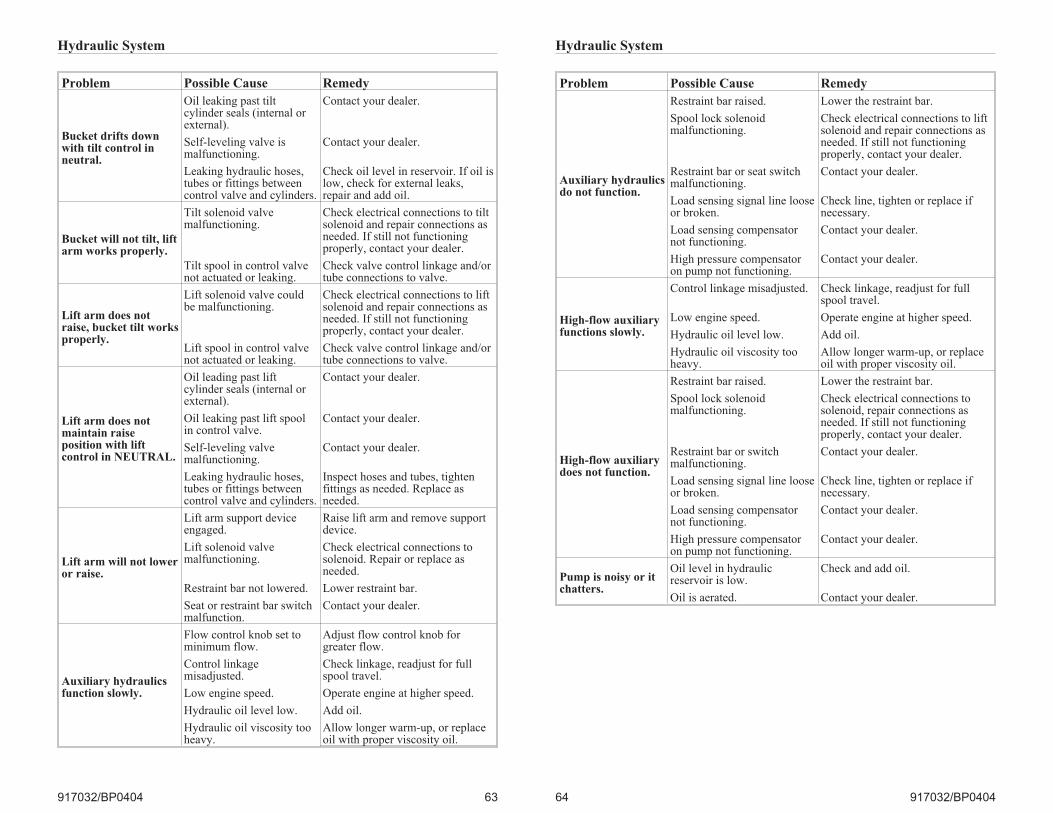
Hydraulic System
917032/BP0404 63
Problem Possible Cause Remedy
Bucket drifts downwith tilt control inneutral.
Oil leaking past tiltcylinder seals (internal orexternal).
Contact your dealer.
Self-leveling valve ismalfunctioning.
Contact your dealer.
Leaking hydraulic hoses,tubes or fittings betweencontrol valve and cylinders.
Check oil level in reservoir. If oil islow, check for external leaks,repair and add oil.
Bucket will not tilt, liftarm works properly.
Tilt solenoid valvemalfunctioning.
Check electrical connections to tiltsolenoid and repair connections asneeded. If still not functioningproperly, contact your dealer.
Tilt spool in control valvenot actuated or leaking.
Check valve control linkage and/ortube connections to valve.
Lift arm does notraise, bucket tilt worksproperly.
Lift solenoid valve couldbe malfunctioning.
Check electrical connections to liftsolenoid and repair connections asneeded. If still not functioningproperly, contact your dealer.
Lift spool in control valvenot actuated or leaking.
Check valve control linkage and/ortube connections to valve.
Lift arm does notmaintain raiseposition with liftcontrol in NEUTRAL.
Oil leading past liftcylinder seals (internal orexternal).
Contact your dealer.
Oil leaking past lift spoolin control valve.
Contact your dealer.
Self-leveling valvemalfunctioning.
Contact your dealer.
Leaking hydraulic hoses,tubes or fittings betweencontrol valve and cylinders.
Inspect hoses and tubes, tightenfittings as needed. Replace asneeded.
Lift arm will not loweror raise.
Lift arm support deviceengaged.
Raise lift arm and remove supportdevice.
Lift solenoid valvemalfunctioning.
Check electrical connections tosolenoid. Repair or replace asneeded.
Restraint bar not lowered. Lower restraint bar.
Seat or restraint bar switchmalfunction.
Contact your dealer.
Auxiliary hydraulicsfunction slowly.
Flow control knob set tominimum flow.
Adjust flow control knob forgreater flow.
Control linkagemisadjusted.
Check linkage, readjust for fullspool travel.
Low engine speed. Operate engine at higher speed.
Hydraulic oil level low. Add oil.
Hydraulic oil viscosity tooheavy.
Allow longer warm-up, or replaceoil with proper viscosity oil.
Hydraulic System
64 917032/BP0404
Problem Possible Cause Remedy
Auxiliary hydraulicsdo not function.
Restraint bar raised. Lower the restraint bar.
Spool lock solenoidmalfunctioning.
Check electrical connections to liftsolenoid and repair connections asneeded. If still not functioningproperly, contact your dealer.
Restraint bar or seat switchmalfunctioning.
Contact your dealer.
Load sensing signal line looseor broken.
Check line, tighten or replace ifnecessary.
Load sensing compensatornot functioning.
Contact your dealer.
High pressure compensatoron pump not functioning.
Contact your dealer.
High-flow auxiliaryfunctions slowly.
Control linkage misadjusted. Check linkage, readjust for fullspool travel.
Low engine speed. Operate engine at higher speed.
Hydraulic oil level low. Add oil.
Hydraulic oil viscosity tooheavy.
Allow longer warm-up, or replaceoil with proper viscosity oil.
High-flow auxiliarydoes not function.
Restraint bar raised. Lower the restraint bar.
Spool lock solenoidmalfunctioning.
Check electrical connections tosolenoid, repair connections asneeded. If still not functioningproperly, contact your dealer.
Restraint bar or switchmalfunctioning.
Contact your dealer.
Load sensing signal line looseor broken.
Check line, tighten or replace ifnecessary.
Load sensing compensatornot functioning.
Contact your dealer.
High pressure compensatoron pump not functioning.
Contact your dealer.
Pump is noisy or itchatters.
Oil level in hydraulicreservoir is low.
Check and add oil.
Oil is aerated. Contact your dealer.
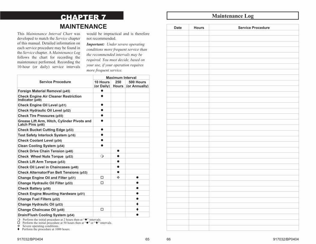
CHAPTER 7
MAINTENANCEThis Maintenance Interval Chart was
developed to match the Service chapter
of this manual. Detailed information on
each service procedure may be found in
the Service chapter. A Maintenance Log
follows the chart for recording the
maintenance performed. Recording the
10-hour (or daily) service intervals
would be impractical and is therefore
not recommended.
Important: Under severe operating
conditions more frequent service than
the recommended intervals may be
required. You must decide, based on
your use, if your operation requires
more frequent service.
917032/BP0404 65
Service ProcedureMaximum Interval
10 Hours(or Daily)
250Hours
500 Hours(or Annually)
Foreign Material Removal (p45) �
Check Engine Air Cleaner RestrictionIndicator (p49)
�
Check Engine Oil Level (p51) �
Check Hydraulic Oil Level (p52) �
Check Tire Pressures (p55) �
Grease Lift Arm, Hitch, Cylinder Pivots andLatch Pins (p46)
�
Check Bucket Cutting Edge (p53) �
Test Safety Interlock System (p16) �
Check Coolant Level (p54) �
Clean Cooling System (p54) �
Check Drive Chain Tension (p48) �
Check Wheel Nuts Torque (p53) � �
Check Lift Arm Torque (p53) �
Check Oil Level in Chaincases (p48) �
Check Alternator/Fan Belt Tensions (p53) �
Change Engine Oil and Filter (p51) � � �
Change Hydraulic Oil Filter (p53) � �
Check Battery (p56) �
Check Engine Mounting Hardware (p51) �
Change Fuel Filters (p52) �
Change Hydraulic Oil (p53) �
Change Chaincase Oil (p48) � �
Drain/Flush Cooling System (p54) �
� Perform the initial procedure at 2 hours then at “�” intervals.� Perform the initial procedure at 50 hours then at “�” or “�” intervals.� Severe operating conditions.� Perform the procedure at 1000 hours.
Maintenance Log
66 917032/BP0404
Date Hours Service Procedure

Maintenance Log
917032/BP0404 67
Date Hours Service Procedure
Maintenance Log
68 917032/BP0404
Date Hours Service Procedure
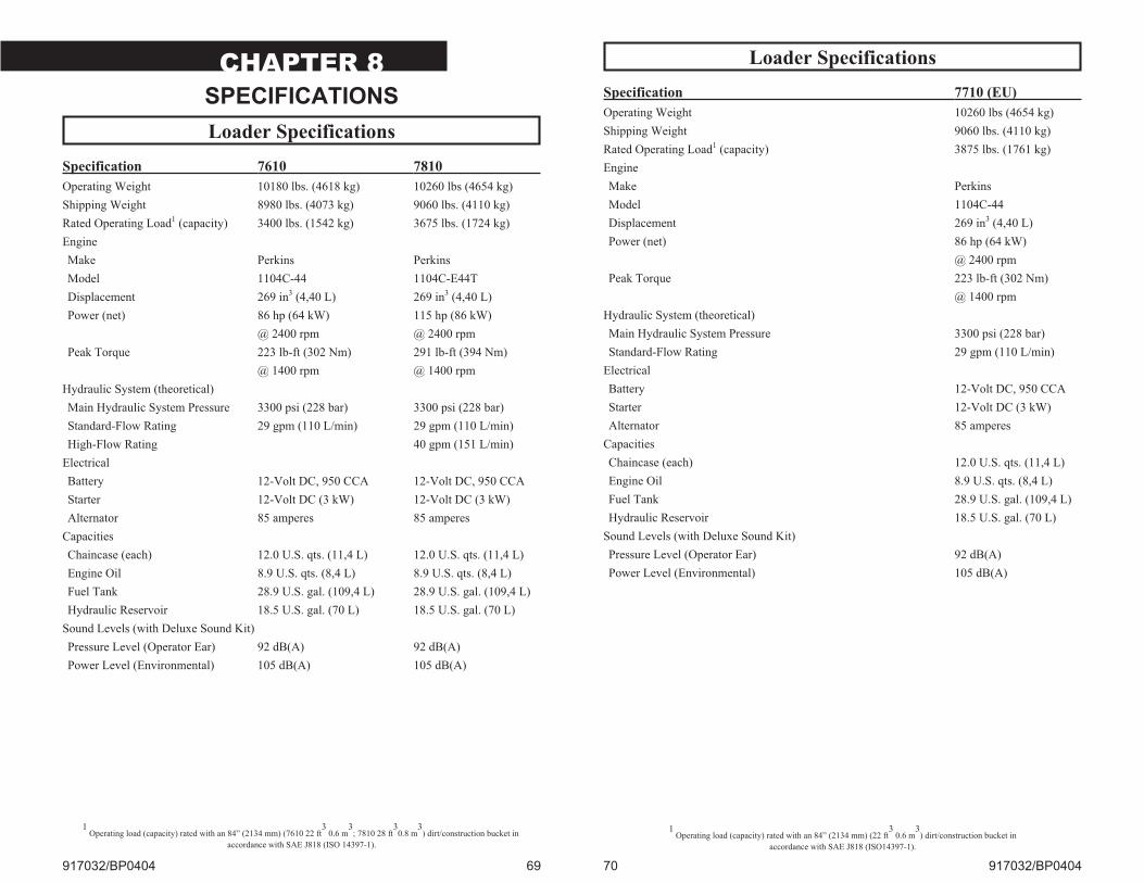
CHAPTER 8
SPECIFICATIONS
Loader Specifications
Specification 7610 7810
Operating Weight 10180 lbs. (4618 kg) 10260 lbs (4654 kg)
Shipping Weight 8980 lbs. (4073 kg) 9060 lbs. (4110 kg)
Rated Operating Load1 (capacity) 3400 lbs. (1542 kg) 3675 lbs. (1724 kg)
Engine
Make Perkins Perkins
Model 1104C-44 1104C-E44T
Displacement 269 in3 (4,40 L) 269 in3 (4,40 L)
Power (net) 86 hp (64 kW) 115 hp (86 kW)
@ 2400 rpm @ 2400 rpm
Peak Torque 223 lb-ft (302 Nm) 291 lb-ft (394 Nm)
@ 1400 rpm @ 1400 rpm
Hydraulic System (theoretical)
Main Hydraulic System Pressure 3300 psi (228 bar) 3300 psi (228 bar)
Standard-Flow Rating 29 gpm (110 L/min) 29 gpm (110 L/min)
High-Flow Rating 40 gpm (151 L/min)
Electrical
Battery 12-Volt DC, 950 CCA 12-Volt DC, 950 CCA
Starter 12-Volt DC (3 kW) 12-Volt DC (3 kW)
Alternator 85 amperes 85 amperes
Capacities
Chaincase (each) 12.0 U.S. qts. (11,4 L) 12.0 U.S. qts. (11,4 L)
Engine Oil 8.9 U.S. qts. (8,4 L) 8.9 U.S. qts. (8,4 L)
Fuel Tank 28.9 U.S. gal. (109,4 L) 28.9 U.S. gal. (109,4 L)
Hydraulic Reservoir 18.5 U.S. gal. (70 L) 18.5 U.S. gal. (70 L)
Sound Levels (with Deluxe Sound Kit)
Pressure Level (Operator Ear) 92 dB(A) 92 dB(A)
Power Level (Environmental) 105 dB(A) 105 dB(A)
917032/BP0404 69
1Operating load (capacity) rated with an 84” (2134 mm) (7610 22 ft
30.6 m
3; 7810 28 ft
30.8 m
3) dirt/construction bucket in
accordance with SAE J818 (ISO 14397-1).
Loader Specifications
Specification 7710 (EU)
Operating Weight 10260 lbs (4654 kg)
Shipping Weight 9060 lbs. (4110 kg)
Rated Operating Load1 (capacity) 3875 lbs. (1761 kg)
Engine
Make Perkins
Model 1104C-44
Displacement 269 in3 (4,40 L)
Power (net) 86 hp (64 kW)
@ 2400 rpm
Peak Torque 223 lb-ft (302 Nm)
@ 1400 rpm
Hydraulic System (theoretical)
Main Hydraulic System Pressure 3300 psi (228 bar)
Standard-Flow Rating 29 gpm (110 L/min)
Electrical
Battery 12-Volt DC, 950 CCA
Starter 12-Volt DC (3 kW)
Alternator 85 amperes
Capacities
Chaincase (each) 12.0 U.S. qts. (11,4 L)
Engine Oil 8.9 U.S. qts. (8,4 L)
Fuel Tank 28.9 U.S. gal. (109,4 L)
Hydraulic Reservoir 18.5 U.S. gal. (70 L)
Sound Levels (with Deluxe Sound Kit)
Pressure Level (Operator Ear) 92 dB(A)
Power Level (Environmental) 105 dB(A)
70 917032/BP0404
1Operating load (capacity) rated with an 84” (2134 mm) (22 ft
30.6 m
3) dirt/construction bucket in
accordance with SAE J818 (ISO14397-1).
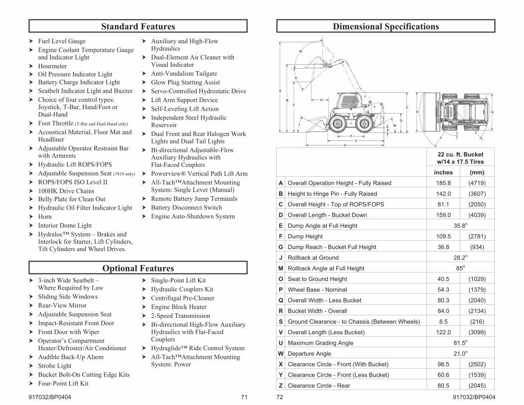
Standard Features
Optional Features
917032/BP0404 71
� Fuel Level Gauge
� Engine Coolant Temperature Gaugeand Indicator Light
� Hourmeter
� Oil Pressure Indicator Light
� Battery Charge Indicator Light
� Seatbelt Indicator Light and Buzzer
� Choice of four control types:Joystick, T-Bar, Hand/Foot orDual-Hand
� Foot Throttle (T-Bar and Dual-Hand only)
� Acoustical Material, Floor Mat andHeadliner
� Adjustable Operator Restraint Barwith Armrests
� Hydraulic Lift ROPS/FOPS
� Adjustable Suspension Seat (7810 only)
� ROPS/FOPS ISO Level II
� 100HK Drive Chains
� Belly Plate for Clean Out
� Hydraulic Oil Filter Indicator Light
� Horn
� Interior Dome Light
� Hydraloc™ System – Brakes andInterlock for Starter, Lift Cylinders,Tilt Cylinders and Wheel Drives.
� Auxiliary and High-FlowHydraulics
� Dual-Element Air Cleaner withVisual Indicator
� Anti-Vandalism Tailgate
� Glow Plug Starting Assist
� Servo-Controlled Hydrostatic Drive
� Lift Arm Support Device
� Self-Leveling Lift Action
� Independent Steel HydraulicReservoir
� Dual Front and Rear Halogen WorkLights and Dual Tail Lights
� Bi-directional Adjustable-FlowAuxiliary Hydraulics withFlat-Faced Couplers
� Powerview® Vertical Path Lift Arm
� All-Tach™Attachment MountingSystem: Single Lever (Manual)
� Remote Battery Jump Terminals
� Battery Disconnect Switch
� Engine Auto-Shutdown System
� 3-inch Wide Seatbelt –Where Required by Law
� Sliding Side Windows
� Rear-View Mirror
� Adjustable Suspension Seat
� Impact-Resistant Front Door
� Front Door with Wiper
� Operator’s CompartmentHeater/Defroster/Air Conditioner
� Audible Back-Up Alarm
� Strobe Light
� Bucket Bolt-On Cutting Edge Kits
� Four-Point Lift Kit
� Single-Point Lift Kit
� Hydraulic Couplers Kit
� Centrifugal Pre-Cleaner
� Engine Block Heater
� 2-Speed Transmission
� Bi-directional High-Flow AuxiliaryHydraulics with Flat-FacedCouplers
� Hydraglide™ Ride Control System
� All-Tach™Attachment MountingSystem: Power
Dimensional Specifications
72 917032/BP0404
22 cu. ft. Bucket
w/14 x 17.5 Tires
inches (mm)
A Overall Operation Height - Fully Raised 185.8 (4719)
B Height to Hinge Pin - Fully Raised 142.0 (3607)
C Overall Height - Top of ROPS/FOPS 81.1 (2050)
D Overall Length - Bucket Down 159.0 (4039)
E Dump Angle at Full Height 35.8o
F Dump Height 109.5 (2781)
G Dump Reach - Bucket Full Height 36.8 (934)
J Rollback at Ground 28.2o
M Rollback Angle at Full Height 85o
O Seat to Ground Height 40.5 (1029)
P Wheel Base - Nominal 54.3 (1379)
Q Overall Width - Less Bucket 80.3 (2040)
R Bucket Width - Overall 84.0 (2134)
S Ground Clearance - to Chassis (Between Wheels) 8.5 (216)
V Overall Length (Less Bucket) 122.0 (3099)
U Maximum Grading Angle 81.5o
W Departure Angle 21.0o
X Clearance Circle - Front (With Bucket) 98.5 (2502)
Y Clearance Circle - Front (Less Bucket) 60.6 (1539)
Z Clearance Circle - Rear 80.5 (2045)
P
V
D
S
O
C
WJ
G
F
B
M
E
A
R Q
X
Y Z
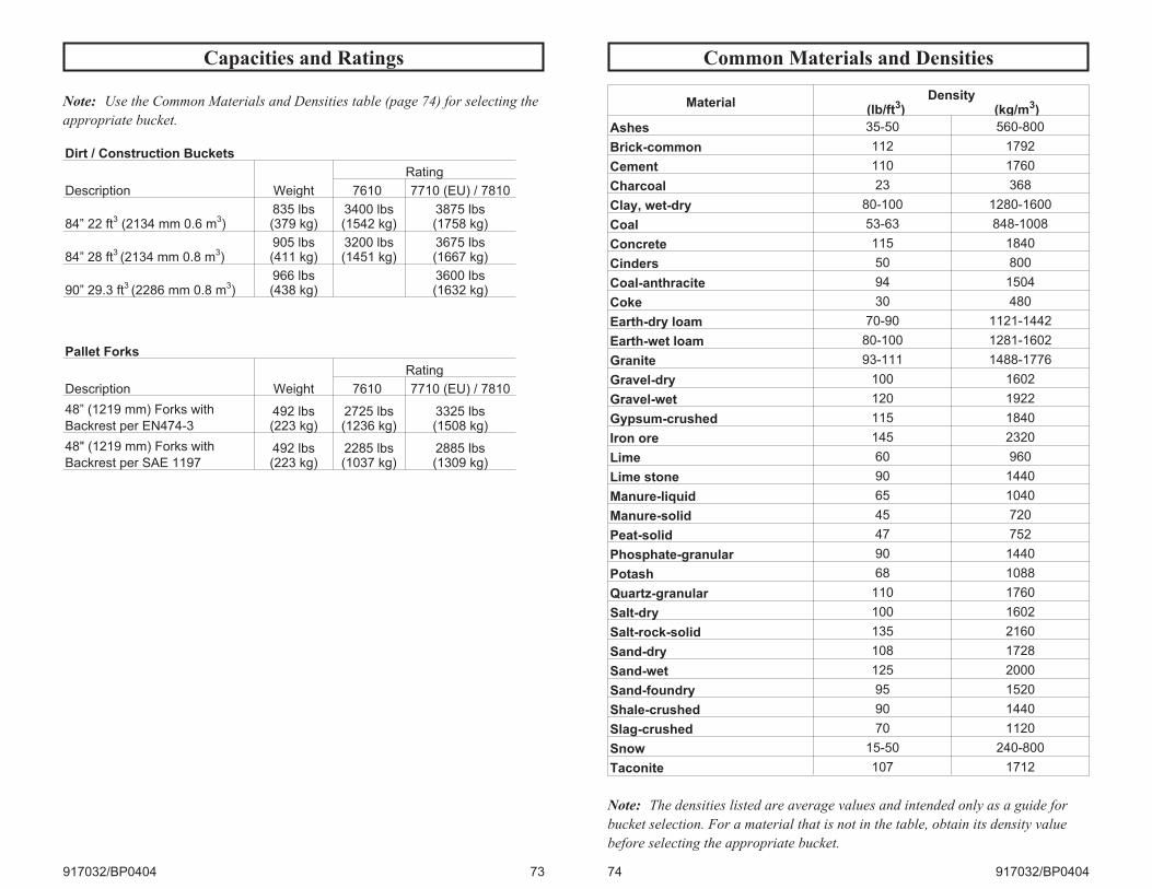
Capacities and Ratings
917032/BP0404 73
Note: Use the Common Materials and Densities table (page 74) for selecting the
appropriate bucket.
Dirt / Construction Buckets
Description Weight
Rating
7610 7710 (EU) / 7810
84” 22 ft3
(2134 mm 0.6 m3)
835 lbs(379 kg)
3400 lbs(1542 kg)
3875 lbs(1758 kg)
84” 28 ft3(2134 mm 0.8 m
3)
905 lbs(411 kg)
3200 lbs(1451 kg)
3675 lbs(1667 kg)
90” 29.3 ft3(2286 mm 0.8 m
3)
966 lbs(438 kg)
3600 lbs(1632 kg)
Pallet Forks
Description Weight
Rating
7610 7710 (EU) / 7810
48” (1219 mm) Forks with
Backrest per EN474-3492 lbs(223 kg)
2725 lbs(1236 kg)
3325 lbs(1508 kg)
48" (1219 mm) Forks with
Backrest per SAE 1197492 lbs(223 kg)
2285 lbs(1037 kg)
2885 lbs(1309 kg)
Common Materials and Densities
74 917032/BP0404
MaterialDensity
(lb/ft3) (kg/m3)
Ashes 35-50 560-800
Brick-common 112 1792
Cement 110 1760
Charcoal 23 368
Clay, wet-dry 80-100 1280-1600
Coal 53-63 848-1008
Concrete 115 1840
Cinders 50 800
Coal-anthracite 94 1504
Coke 30 480
Earth-dry loam 70-90 1121-1442
Earth-wet loam 80-100 1281-1602
Granite 93-111 1488-1776
Gravel-dry 100 1602
Gravel-wet 120 1922
Gypsum-crushed 115 1840
Iron ore 145 2320
Lime 60 960
Lime stone 90 1440
Manure-liquid 65 1040
Manure-solid 45 720
Peat-solid 47 752
Phosphate-granular 90 1440
Potash 68 1088
Quartz-granular 110 1760
Salt-dry 100 1602
Salt-rock-solid 135 2160
Sand-dry 108 1728
Sand-wet 125 2000
Sand-foundry 95 1520
Shale-crushed 90 1440
Slag-crushed 70 1120
Snow 15-50 240-800
Taconite 107 1712
Note: The densities listed are average values and intended only as a guide for
bucket selection. For a material that is not in the table, obtain its density value
before selecting the appropriate bucket.
Bucket Selection
To use the table, find the material to be
loaded and read its maximum density.
Then multiply the volumetric rating of
the attachment by the material density
to determine if the attachment can
safely be used. See page 73 for a listing
of attachments and their load ratings.
Note: Where the material density is
listed as a range (clay at 80-100 lb/ft3,
for example), always use the maximum
density (100 lb/ft3 in this example) for
making calculations. Also, see the
following examples.
Example 1: If clay (density of 80-100
lb/ft3) is to be hauled using a SL7810
model loader using a 28 ft3
Dirt/Construction bucket, the bucket
capacity is 28 ft3 and the loader rating is
3675 lbs. Multiply the density of clay
(100 lb/ft3) by the capacity of the bucket
(28 ft3) to achieve the weight to be
carried (100 lb/ft3 x 28 ft3 = 2800
lbs). This number is less than the
machine rating, allowing safe use of this
bucket in this application.
Example 2: If granite (density of
1488-1776 kg/m3) is to be hauled using
a SL7610 model loader using a 0.6 m3
Dirt/Construction bucket, the bucket
capacity is 0.6 m3 and the loader rating
is 1486 kg. Multiply the density of
granite (1776 kg/m3) by the capacity of
the bucket (0.6 m3) to achieve the
weight to be carried (1776 kg/m3 x 0.6
m3 = 1066 kg). This number is less than
the machine rating, allowing safe use of
this bucket in this application.
917032/BP0404 75
Notes
76 917032/BP0404
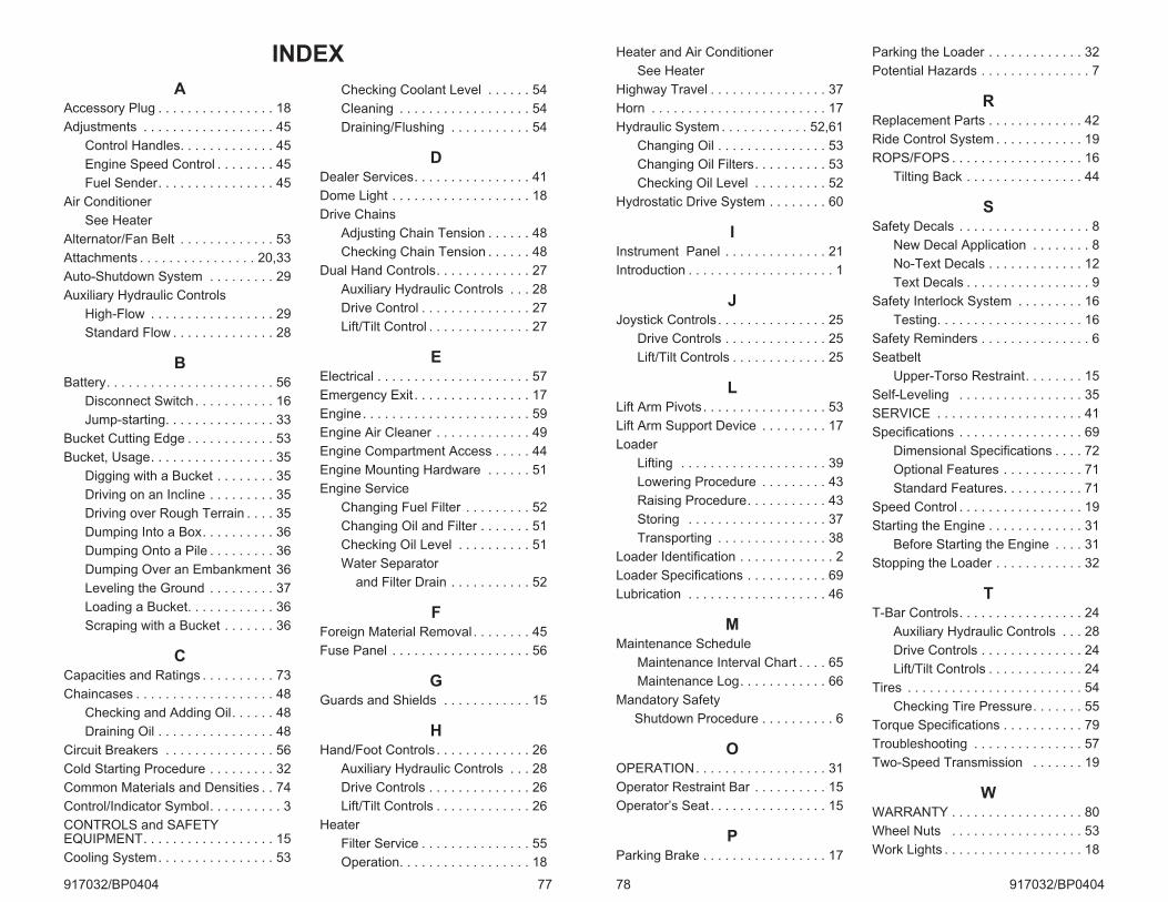
INDEX
AAccessory Plug . . . . . . . . . . . . . . . . 18
Adjustments . . . . . . . . . . . . . . . . . . 45
Control Handles. . . . . . . . . . . . . 45
Engine Speed Control . . . . . . . . 45
Fuel Sender. . . . . . . . . . . . . . . . 45
Air Conditioner
See Heater
Alternator/Fan Belt . . . . . . . . . . . . . 53
Attachments . . . . . . . . . . . . . . . . 20,33
Auto-Shutdown System . . . . . . . . . 29
Auxiliary Hydraulic Controls
High-Flow . . . . . . . . . . . . . . . . . 29
Standard Flow . . . . . . . . . . . . . . 28
BBattery. . . . . . . . . . . . . . . . . . . . . . . 56
Disconnect Switch . . . . . . . . . . . 16
Jump-starting. . . . . . . . . . . . . . . 33
Bucket Cutting Edge . . . . . . . . . . . . 53
Bucket, Usage. . . . . . . . . . . . . . . . . 35
Digging with a Bucket . . . . . . . . 35
Driving on an Incline . . . . . . . . . 35
Driving over Rough Terrain . . . . 35
Dumping Into a Box. . . . . . . . . . 36
Dumping Onto a Pile . . . . . . . . . 36
Dumping Over an Embankment 36
Leveling the Ground . . . . . . . . . 37
Loading a Bucket. . . . . . . . . . . . 36
Scraping with a Bucket . . . . . . . 36
CCapacities and Ratings . . . . . . . . . . 73
Chaincases . . . . . . . . . . . . . . . . . . . 48
Checking and Adding Oil. . . . . . 48
Draining Oil . . . . . . . . . . . . . . . . 48
Circuit Breakers . . . . . . . . . . . . . . . 56
Cold Starting Procedure . . . . . . . . . 32
Common Materials and Densities . . 74
Control/Indicator Symbol. . . . . . . . . . 3
CONTROLS and SAFETYEQUIPMENT. . . . . . . . . . . . . . . . . . 15
Cooling System. . . . . . . . . . . . . . . . 53
Checking Coolant Level . . . . . . 54
Cleaning . . . . . . . . . . . . . . . . . . 54
Draining/Flushing . . . . . . . . . . . 54
DDealer Services. . . . . . . . . . . . . . . . 41
Dome Light . . . . . . . . . . . . . . . . . . . 18
Drive Chains
Adjusting Chain Tension . . . . . . 48
Checking Chain Tension . . . . . . 48
Dual Hand Controls. . . . . . . . . . . . . 27
Auxiliary Hydraulic Controls . . . 28
Drive Control . . . . . . . . . . . . . . . 27
Lift/Tilt Control . . . . . . . . . . . . . . 27
EElectrical . . . . . . . . . . . . . . . . . . . . . 57
Emergency Exit . . . . . . . . . . . . . . . . 17
Engine. . . . . . . . . . . . . . . . . . . . . . . 59
Engine Air Cleaner . . . . . . . . . . . . . 49
Engine Compartment Access . . . . . 44
Engine Mounting Hardware . . . . . . 51
Engine Service
Changing Fuel Filter . . . . . . . . . 52
Changing Oil and Filter . . . . . . . 51
Checking Oil Level . . . . . . . . . . 51
Water Separator
and Filter Drain . . . . . . . . . . . 52
FForeign Material Removal . . . . . . . . 45
Fuse Panel . . . . . . . . . . . . . . . . . . . 56
GGuards and Shields . . . . . . . . . . . . 15
HHand/Foot Controls . . . . . . . . . . . . . 26
Auxiliary Hydraulic Controls . . . 28
Drive Controls . . . . . . . . . . . . . . 26
Lift/Tilt Controls . . . . . . . . . . . . . 26
Heater
Filter Service . . . . . . . . . . . . . . . 55
Operation. . . . . . . . . . . . . . . . . . 18
917032/BP0404 77
Heater and Air Conditioner
See Heater
Highway Travel . . . . . . . . . . . . . . . . 37
Horn . . . . . . . . . . . . . . . . . . . . . . . . 17
Hydraulic System . . . . . . . . . . . . 52,61
Changing Oil . . . . . . . . . . . . . . . 53
Changing Oil Filters. . . . . . . . . . 53
Checking Oil Level . . . . . . . . . . 52
Hydrostatic Drive System . . . . . . . . 60
IInstrument Panel . . . . . . . . . . . . . . 21
Introduction . . . . . . . . . . . . . . . . . . . . 1
JJoystick Controls . . . . . . . . . . . . . . . 25
Drive Controls . . . . . . . . . . . . . . 25
Lift/Tilt Controls . . . . . . . . . . . . . 25
LLift Arm Pivots . . . . . . . . . . . . . . . . . 53
Lift Arm Support Device . . . . . . . . . 17
Loader
Lifting . . . . . . . . . . . . . . . . . . . . 39
Lowering Procedure . . . . . . . . . 43
Raising Procedure. . . . . . . . . . . 43
Storing . . . . . . . . . . . . . . . . . . . 37
Transporting . . . . . . . . . . . . . . . 38
Loader Identification . . . . . . . . . . . . . 2
Loader Specifications . . . . . . . . . . . 69
Lubrication . . . . . . . . . . . . . . . . . . . 46
MMaintenance Schedule
Maintenance Interval Chart . . . . 65
Maintenance Log. . . . . . . . . . . . 66
Mandatory Safety
Shutdown Procedure . . . . . . . . . . 6
OOPERATION. . . . . . . . . . . . . . . . . . 31
Operator Restraint Bar . . . . . . . . . . 15
Operator’s Seat . . . . . . . . . . . . . . . . 15
PParking Brake . . . . . . . . . . . . . . . . . 17
Parking the Loader . . . . . . . . . . . . . 32
Potential Hazards . . . . . . . . . . . . . . . 7
RReplacement Parts . . . . . . . . . . . . . 42
Ride Control System . . . . . . . . . . . . 19
ROPS/FOPS . . . . . . . . . . . . . . . . . . 16
Tilting Back . . . . . . . . . . . . . . . . 44
SSafety Decals . . . . . . . . . . . . . . . . . . 8
New Decal Application . . . . . . . . 8
No-Text Decals . . . . . . . . . . . . . 12
Text Decals . . . . . . . . . . . . . . . . . 9
Safety Interlock System . . . . . . . . . 16
Testing. . . . . . . . . . . . . . . . . . . . 16
Safety Reminders . . . . . . . . . . . . . . . 6
Seatbelt
Upper-Torso Restraint. . . . . . . . 15
Self-Leveling . . . . . . . . . . . . . . . . . 35
SERVICE . . . . . . . . . . . . . . . . . . . . 41
Specifications . . . . . . . . . . . . . . . . . 69
Dimensional Specifications . . . . 72
Optional Features . . . . . . . . . . . 71
Standard Features. . . . . . . . . . . 71
Speed Control . . . . . . . . . . . . . . . . . 19
Starting the Engine . . . . . . . . . . . . . 31
Before Starting the Engine . . . . 31
Stopping the Loader . . . . . . . . . . . . 32
TT-Bar Controls. . . . . . . . . . . . . . . . . 24
Auxiliary Hydraulic Controls . . . 28
Drive Controls . . . . . . . . . . . . . . 24
Lift/Tilt Controls . . . . . . . . . . . . . 24
Tires . . . . . . . . . . . . . . . . . . . . . . . . 54
Checking Tire Pressure. . . . . . . 55
Torque Specifications . . . . . . . . . . . 79
Troubleshooting . . . . . . . . . . . . . . . 57
Two-Speed Transmission . . . . . . . 19
WWARRANTY . . . . . . . . . . . . . . . . . . 80
Wheel Nuts . . . . . . . . . . . . . . . . . . 53
Work Lights . . . . . . . . . . . . . . . . . . . 18
78 917032/BP0404
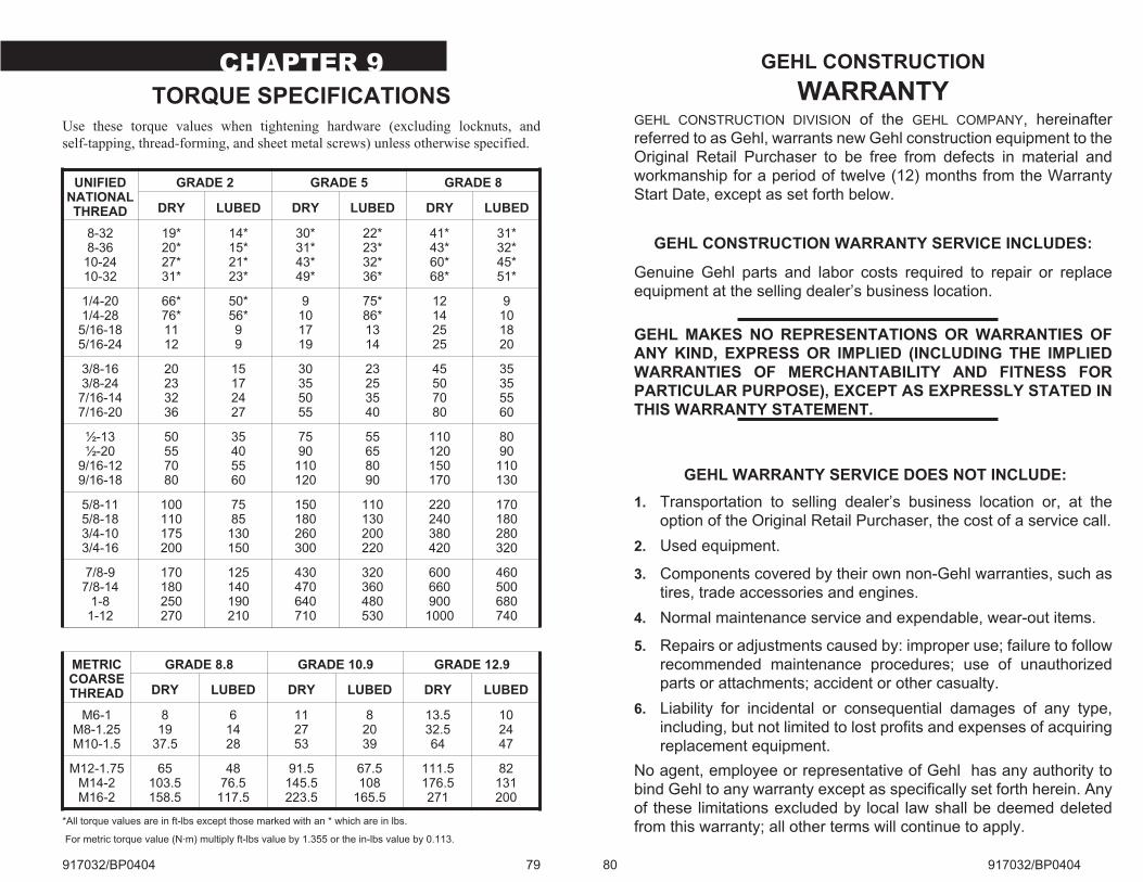
CHAPTER 9
TORQUE SPECIFICATIONS
917032/BP0404 79
UNIFIEDNATIONALTHREAD
GRADE 2 GRADE 5 GRADE 8
DRY LUBED DRY LUBED DRY LUBED
8-328-3610-2410-32
19*20*27*31*
14*15*21*23*
30*31*43*49*
22*23*32*36*
41*43*60*68*
31*32*45*51*
1/4-201/4-285/16-185/16-24
66*76*1112
50*56*99
9101719
75*86*1314
12142525
9101820
3/8-163/8-247/16-147/16-20
20233236
15172427
30355055
23253540
45507080
35355560
½-13½-20
9/16-129/16-18
50557080
35405560
7590110120
55658090
110120150170
8090
110130
5/8-115/8-183/4-103/4-16
100110175200
7585130150
150180260300
110130200220
220240380420
170180280320
7/8-97/8-14
1-81-12
170180250270
125140190210
430470640710
320360480530
600660900
1000
460500680740
METRICCOARSETHREAD
GRADE 8.8 GRADE 10.9 GRADE 12.9
DRY LUBED DRY LUBED DRY LUBED
M6-1M8-1.25M10-1.5
819
37.5
61428
112753
82039
13.532.564
102447
M12-1.75M14-2M16-2
65103.5158.5
4876.5117.5
91.5145.5223.5
67.5108
165.5
111.5176.5271
82131200
*All torque values are in ft-lbs except those marked with an * which are in lbs.
For metric torque value (N·m) multiply ft-lbs value by 1.355 or the in-lbs value by 0.113.
Use these torque values when tightening hardware (excluding locknuts, and
self-tapping, thread-forming, and sheet metal screws) unless otherwise specified.
80 917032/BP0404
GEHL CONSTRUCTION
WARRANTYGEHL CONSTRUCTION DIVISION of the GEHL COMPANY, hereinafter
referred to as Gehl, warrants new Gehl construction equipment to the
Original Retail Purchaser to be free from defects in material and
workmanship for a period of twelve (12) months from the Warranty
Start Date, except as set forth below.
GEHL CONSTRUCTION WARRANTY SERVICE INCLUDES:
Genuine Gehl parts and labor costs required to repair or replace
equipment at the selling dealer’s business location.
GEHL MAKES NO REPRESENTATIONS OR WARRANTIES OF
ANY KIND, EXPRESS OR IMPLIED (INCLUDING THE IMPLIED
WARRANTIES OF MERCHANTABILITY AND FITNESS FOR
PARTICULAR PURPOSE), EXCEPT AS EXPRESSLY STATED IN
THIS WARRANTY STATEMENT.
GEHL WARRANTY SERVICE DOES NOT INCLUDE:
1. Transportation to selling dealer’s business location or, at the
option of the Original Retail Purchaser, the cost of a service call.
2. Used equipment.
3. Components covered by their own non-Gehl warranties, such as
tires, trade accessories and engines.
4. Normal maintenance service and expendable, wear-out items.
5. Repairs or adjustments caused by: improper use; failure to follow
recommended maintenance procedures; use of unauthorized
parts or attachments; accident or other casualty.
6. Liability for incidental or consequential damages of any type,
including, but not limited to lost profits and expenses of acquiring
replacement equipment.
No agent, employee or representative of Gehl has any authority to
bind Gehl to any warranty except as specifically set forth herein. Any
of these limitations excluded by local law shall be deemed deleted
from this warranty; all other terms will continue to apply.
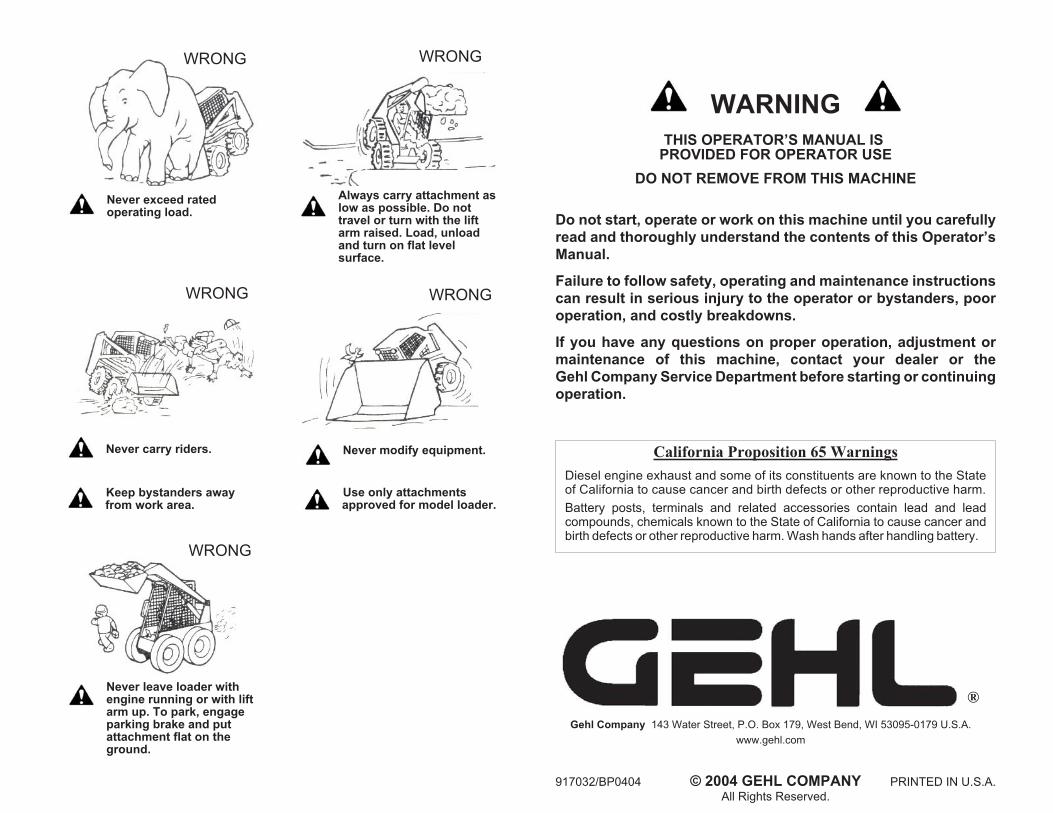
Never exceed ratedoperating load.
Never carry riders.
Keep bystanders awayfrom work area.
Never leave loader withengine running or with liftarm up. To park, engageparking brake and putattachment flat on theground.
Always carry attachment aslow as possible. Do nottravel or turn with the liftarm raised. Load, unloadand turn on flat levelsurface.
Never modify equipment.
Use only attachmentsapproved for model loader.
WRONG
WRONG
WRONG
WRONG
WRONG
917032/BP0404 © 2004 GEHL COMPANY PRINTED IN U.S.A.
All Rights Reserved.
WARNING
THIS OPERATOR’S MANUAL ISPROVIDED FOR OPERATOR USE
DO NOT REMOVE FROM THIS MACHINE
Do not start, operate or work on this machine until you carefully
read and thoroughly understand the contents of this Operator’s
Manual.
Failure to follow safety, operating and maintenance instructions
can result in serious injury to the operator or bystanders, poor
operation, and costly breakdowns.
If you have any questions on proper operation, adjustment or
maintenance of this machine, contact your dealer or the
Gehl Company Service Department before starting or continuing
operation.
California Proposition 65 Warnings
Diesel engine exhaust and some of its constituents are known to the Stateof California to cause cancer and birth defects or other reproductive harm.
Battery posts, terminals and related accessories contain lead and leadcompounds, chemicals known to the State of California to cause cancer andbirth defects or other reproductive harm. Wash hands after handling battery.
®
Gehl Company 143 Water Street, P.O. Box 179, West Bend, WI 53095-0179 U.S.A.
www.gehl.com