Embed Size (px)
Citation preview


1
Forex LVL 1.55E - 2580Fb
7 1/4'' to 24''
FOREX LVL(LAMINATED VENEER LUMBER)
1 3/4''
NOTES
1. Tabulated values are specified strengths for standard term duration of load. Specified strengths shall be permitted to be adjusted for other load durations as permitted by the code
2. Tabulated values do not include the resistance factor
3. Tabulated bending specified strength (fb) for FOREX LVL 2580Fb- 1.55E are based on a reference depth of 12 inches. For other depth, the tabulated bending stress (fb) must be adjusted by a size factor Kzb
Where : Kzb= (12/d)1/8
4. The deflection of a simple span beam with a uniformly distributed load is calculated as follows
Δ= 270 WL4
Ebd3
Where : D = total deflection (in) E = modulus of elasticity (psi) W = applied uniform load (lb/ft) b = member thickness (in) L = design span (ft) d = member depth (in)
5. Tabulated tension parallel to grain specified strength (ft) is applicable to lengths up to 20 feet.
For lengths greater than 20 feet, the tabulated tension to grain specified strength (ft) must be adjusted by the length fator Kzt
Where : Kzt = (20/L) 0.146
L = length of the member (ft)
6. Tabulated longitudinal shear specified strengths (Fv) have a shear size factor Kzv=1.0
7. Applicable to all tabulated values except Specific Gravity (SG)
8. Applicable for nailed connection
9. Applicable for bolted connection
Bending (3) Fb = 2580 Longitudinal shear perpendicular to glue line –joist /beam(6) Fv = 250
Modulus of elasticity apparent (4) E = 1,55 Longitudinal shear parallel to glue line - plank (6) Fv = 165
Tension parallel to grain (5) Ft = 1780 Specific Gravity – Lateral, Nails in Face (8) SG = 0,46
Compression perpendicular to grain- joist / beam Fcp = 510 Specific Gravity – Lateral, Nails in Edge (8) SG = 0,42
Compression perpendicular to grain - plank Fcp = 260 Specific Gravity – Lateral, Bolts in Face (9) SG = 0,40
Compression parallel to grain Fc = 2375 Specific Gravity – Withdrawal, Nails in Face and in Edge (8) SG = 0,44
DESIGN PROPERTIES FOREX LVL 2580Fb - 1.55E

DESIGNED TO PERFORMFOREX laminated veneer lumber (LVL) is made from ultrasonically graded veneers assembled longitudinally(all plys in the same direction) to yield maximum strength. Top grade veneers have few imperfections. Scanners are used to identify defects from the lower quality veneers. A machine specially designed eliminatesthe faulty parts and assembles the good material yeilding strong and uniform veneers. Veneer combinationssuited for the different grades are then assembled using waterproof adhesives under heat and pressure. Forex LVL can be used as single ply or as assembled beams which are exceptionally strong, strait and solid.Forex LVL is available in custom lengths and width further increasing its value to builders.
AVAILABLE GRADESForex LVL is available in 2 grades : 3100Fb – 2.0E, 2580Fb - 1.55E. It comes in a variety of depths and lengthsup to 60 feets . The standard natural finish accepts good quality structural adhesives. It can be built-up onsite or factory laminated which eliminate the need for nailing. The product also comes with a water resistantcoating to protect the LVL during construction and warehousing.
RELIABLE DESIGNForex LVL design values can be incorporated to in house or external softwares to speed up the design and improve accuracy.
PRODUCT CERTIFICATIONForex LVL is certified under – APA - program based on ASTM 5456 standard.
2

CONTENTSHANDLING, STORAGE & USAGE GUIDELINES 4
FOREX LVL INSTALLATION DETAILS 4
MULTIPLE MEMBER CONNECTION 5
BEAM HOLE DETAILS 6
PRODUCT SPECIFICATIONS & DESIGN VALUES 7
PRODUCT IDENTIFICATION MARKINGS 7
NOTES FOR USE OF ALLOWABLE UNIFORM FLOOR AND ROOF LOADS TABLES 8
ALLOWABLE UNIFORM FLOOR LOADS (PLF) – 100% 1 - Ply 1 3/4 ” 9
ALLOWABLE UNIFORM FLOOR LOADS (PLF) – 100% 2 - Ply 3 1/2 ” 10
ALLOWABLE UNIFORM FLOOR LOADS (PLF) – 100% 3 - Ply 5 1/4 ” 11
ALLOWABLE UNIFORM FLOOR LOADS (PLF) – 100% 4 - Ply 7 ” 12
ALLOWABLE UNIFORM ROOF LOADS (PLF) – 115% (SNOW) 1 - Ply 1 3/4 ” 13
ALLOWABLE UNIFORM ROOF LOADS (PLF) – 115% (SNOW) 2 - Ply 3 1/2 ” 14
ALLOWABLE UNIFORM ROOF LOADS (PLF) – 115% (SNOW) 3 - Ply 5 1/4 ” 15
ALLOWABLE UNIFORM ROOF LOADS (PLF) – 115% (SNOW) 4 - Ply 7 ” 16
MINIMUM BEARING LENGTH REQUIREMENTS 17
WARRANTY 17
4
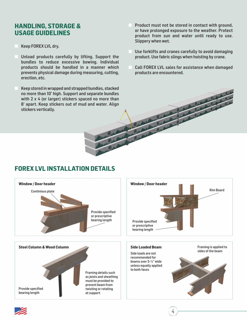
HANDLING, STORAGE & USAGE GUIDELINES
n Keep FOREX LVL dry.
n Unload products carefully by lifting. Support the bundles to reduce excessive bowing. Individual products should be handled in a manner which prevents physical damage during measuring, cutting, erection, etc.
n Keep stored in wrapped and strapped bundles, stacked no more than 10’ high. Support and separate bundles with 2 x 4 (or larger) stickers spaced no more than 8’ apart. Keep stickers out of mud and water. Align stickers vertically.
FOREX LVL INSTALLATION DETAILS
n Product must not be stored in contact with ground, or have prolonged exposure to the weather. Protect product from sun and water until ready to use. Slippery when wet.
n Use forklifts and cranes carefully to avoid damaging product. Use fabric slings when hoisting by crane.
n Call FOREX LVL sales for assistance when damaged products are encountered.
Window / Door header Window / Door header
Steel Column & Wood Column Side Loaded Beam
Continious plate
Provide specifiedor prescriptivebearing length
Provide specifiedbearing length
Framing details suchas joists and sheathingmust be provided toprevent beam fromtwisting or rotating at support
Side loads are not recommended forbeams over 5-½” wideunless equally appliedto both faces
Framing is applied tosides of the beam
Provide specifiedor prescriptivebearing length
Rim Board
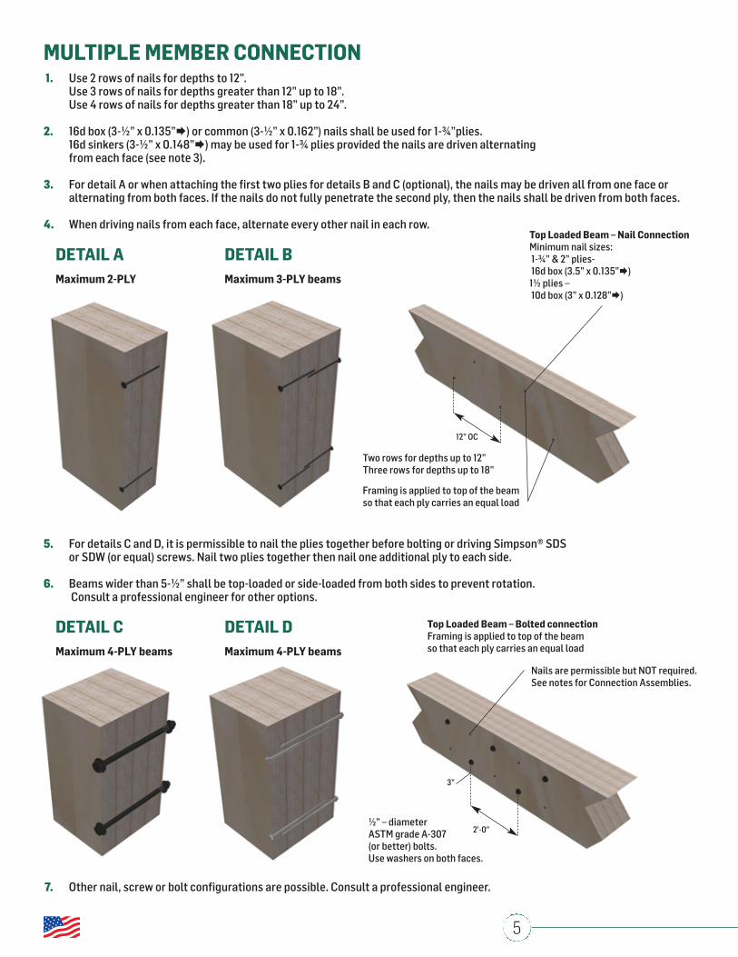
Top Loaded Beam – Bolted connectionFraming is applied to top of the beamso that each ply carries an equal load
Nails are permissible but NOT required.See notes for Connection Assemblies.
½” – diameterASTM grade A-307(or better) bolts.Use washers on both faces.
3”
2’-0”
5
MULTIPLE MEMBER CONNECTION1. Use 2 rows of nails for depths to 12”. Use 3 rows of nails for depths greater than 12” up to 18”. Use 4 rows of nails for depths greater than 18” up to 24”.
2. 16d box (3-½” x 0.135”) or common (3-½” x 0.162”) nails shall be used for 1-¾”plies. 16d sinkers (3-½” x 0.148”) may be used for 1-¾ plies provided the nails are driven alternating from each face (see note 3).
3. For detail A or when attaching the first two plies for details B and C (optional), the nails may be driven all from one face or alternating from both faces. If the nails do not fully penetrate the second ply, then the nails shall be driven from both faces.
4. When driving nails from each face, alternate every other nail in each row.
5. For details C and D, it is permissible to nail the plies together before bolting or driving Simpson® SDS or SDW (or equal) screws. Nail two plies together then nail one additional ply to each side.
6. Beams wider than 5-½” shall be top-loaded or side-loaded from both sides to prevent rotation. Consult a professional engineer for other options.
7. Other nail, screw or bolt configurations are possible. Consult a professional engineer.
DETAIL AMaximum 2-PLY
DETAIL CMaximum 4-PLY beams
DETAIL DMaximum 4-PLY beams
DETAIL BMaximum 3-PLY beams
Top Loaded Beam – Nail Connection Minimum nail sizes:1-¾” & 2” plies-16d box (3.5” x 0.135”)
1½ plies –10d box (3” x 0.128”)
Two rows for depths up to 12”Three rows for depths up to 18”
Framing is applied to top of the beamso that each ply carries an equal load
12” OC

6
BEAM HOLE DETAILS
NOTES
1. THE Allowed Hole Zone in this chart is suitable for Uniformly loaded beams using maximum loads for any tables listed. For other load conditions or hole configurations, please contact FOREX LVL.
2. If more than one hole is to be cut in the beam, the length of the uncut beam between holes must be a minimum of twice the diameter of the largest hole.
3. Rectangular holes are not allowed.
4. Holes in cantilevers require additional analysis.
Beam Depths 5-½” 7-¼” 9-¼” 11-¼” 11-⅞” 14” 16” 18” 20” 22” 24”
Maximum Hole diameter 1-⅛” 1-½” 2” 2” 2” 2” 2” 2” 2” 2” 2”

7
PRODUCT SPECIFICATIONS & DESIGN VALUES
FOREX LVL 2580Fb- 1.55E 1-¾” – ALLOWABLE DESIGN PROPERTIES
PRODUCT IDENTIFICATION MARKINGS
NOTES
1. The design properties table has been developed using the provisions of National Design Specification® for Wood Construction 2015 Edition and the allowable stress design properties provided in APA Product Report® PR-L318.
2. The design properties are applicable to loading in a beam orientation with lateral support at bearing points and continuous lateral support along the compression edge of the beam.
3. Design properties are based on dry service conditions only.
4. All single ply beams are limited to a depth of 14’’ maximum. Plies that are 16’’ or deeper must be used in multiple-ply applications.
5. The design properties table does not include the repetitive load factor (Cr=1.04) for beams with two plies or more.
6. The design properties table does not include the effect of allowable holes.
7. Stiffness values (EI) are based on the apparent modulus of elasticity (E=1.55x10⁶ psi) and the effect of shear deformation has been included.

8
Notes for Use of Allowable Uniform Floor and Roof Loads Tables
1. The load tables have been developed using the provisions of National Design Specification® for Wood Construction 2015 Edition and the allowable stress design properties provided in APA Product Report® PR-L318.
2. The load tables are not intended to substitute the provision of services by a structural engineer according to local project requirements. For any beam configurations that do not correspond to the assumptions of this table, the services of a structural engineer may be required.
3. The load tables are based on the maximum uniform load for floor (100% duration) or roof (115% duration) applications in residential buildings, using the most restrictive of either simple spans or continuous spans of equal length. The span length is measured from the centre of the supports. The loads shown in the tables may be added to the self-weight of the beam.
4. Forex 1.55E LVL must only be used in dry service conditions where the moisture content of the LVL will be maintained at 16% or less.
5. LVL beams require lateral support at beam bearing points and continuous lateral support of the compression edge of the beam.
6. All single ply beams are limited to a depth of 14’’ maximum. Plies that are 16’’ or deeper must be used in multiple-ply applications.
7. Deflection limits must be verified with local building code and project requirements. The deflection limits used in the tables for floors (100% duration) are L/360 for live load and L/240 for total load. The deflection limits used in the tables for roofs (115% duration) are L/240 for live load and L/180 for total load.
8. To use the tables, the user must check that both the live load and the total load values listed are not exceeded for a given span. Where the symbol “ * ” is shown for the allowable live load , the total load governs the design, unless the user has chosen a more stringent limit for the live load deflection (see notes 9 and 10).
9. To apply live load deflection limits of L/480 or L/600 for floor applications (100% duration), multiply the allowable load in the Live Load L/360 row by 0.75 or 0.5 respectively.
10. To apply live load deflection limits of L/360 or L/480 for roof applications (115% duration), multiply the allowable load in the Live Load L/240 row by 0.67 or 0.5 respectively.
11. If the actual span of the beam falls in between two span lengths in the SPAN column, use the allowable loads given for the greater span length.
12. The load tables include the repetitive load factor (Cr=1.04) for beams with two plies or more.
13. The load tables include the effect of allowable holes in the middle 1/3 of the depth and the middle 1/3 of the span, all according to the guidelines provided in this product manual.
14. The bearing conditions in the load table assume bearing across the full width of the beam, and a bearing material that has a bearing strength equivalent or greater than Forex 1.55E LVL (510 psi). The load tables include an assumed maximum available bearing length of 4 ½’’ at the exterior supports of the beam.
15. For applications where the total load does not exceed the value given in the table, the length of bearing values may be reduced proportionately.

9
ALLOWABLE UNIFORM FLOOR LOADS (PLF) – 100%(Can be applied to the beam in addition to its own weight.)
Notes
1. Deflection limits must be verified with local building code and project requirements. The deflection limits used in the tables for floors (100% duration) are L/360 for live load and L/240 for total load. The deflection limits used in the tables for roofs (115% duration) are L/240 for live load and L/180 for total load. 2. The bearing conditions in the load table assume bearing across the full width of the beam, and a bearing material that has a bearing strength equivalent or greater than Forex 1.55E LVL (510 psi). The load tables include an assumed maximum available bearing length of 4 ½’’ at the exterior supports of the beam.

10
ALLOWABLE UNIFORM FLOOR LOADS (PLF) – 100%(Can be applied to the beam in addition to its own weight.)
Notes
1. Deflection limits must be verified with local building code and project requirements. The deflection limits used in the tables for floors (100% duration) are L/360 for live load and L/240 for total load. The deflection limits used in the tables for roofs (115% duration) are L/240 for live load and L/180 for total load. 2. The bearing conditions in the load table assume bearing across the full width of the beam, and a bearing material that has a bearing strength equivalent or greater than Forex 1.55E LVL (510 psi). The load tables include an assumed maximum available bearing length of 4 ½’’ at the exterior supports of the beam.

11
ALLOWABLE UNIFORM FLOOR LOADS (PLF) – 100%(Can be applied to the beam in addition to its own weight.)
Notes
1. Deflection limits must be verified with local building code and project requirements. The deflection limits used in the tables for floors (100% duration) are L/360 for live load and L/240 for total load. The deflection limits used in the tables for roofs (115% duration) are L/240 for live load and L/180 for total load. 2. The bearing conditions in the load table assume bearing across the full width of the beam, and a bearing material that has a bearing strength equivalent or greater than Forex 1.55E LVL (510 psi). The load tables include an assumed maximum available bearing length of 4 ½’’ at the exterior supports of the beam.

12
ALLOWABLE UNIFORM FLOOR LOADS (PLF) – 100%(Can be applied to the beam in addition to its own weight.)
Notes
1. Deflection limits must be verified with local building code and project requirements. The deflection limits used in the tables for floors (100% duration) are L/360 for live load and L/240 for total load. The deflection limits used in the tables for roofs (115% duration) are L/240 for live load and L/180 for total load. 2. The bearing conditions in the load table assume bearing across the full width of the beam, and a bearing material that has a bearing strength equivalent or greater than Forex 1.55E LVL (510 psi). The load tables include an assumed maximum available bearing length of 4 ½’’ at the exterior supports of the beam.

13
ALLOWABLE UNIFORM ROOF LOADS (PLF) – 115% (SNOW)(Can be applied to the beam in addition to its own weight.)
Notes
1. Deflection limits must be verified with local building code and project requirements. The deflection limits used in the tables for floors (100% duration) are L/360 for live load and L/240 for total load. The deflection limits used in the tables for roofs (115% duration) are L/240 for live load and L/180 for total load. 2. The bearing conditions in the load table assume bearing across the full width of the beam, and a bearing material that has a bearing strength equivalent or greater than Forex 1.55E LVL (510 psi). The load tables include an assumed maximum available bearing length of 4 ½’’ at the exterior supports of the beam.

14
ALLOWABLE UNIFORM ROOF LOADS (PLF) – 115% (SNOW)(Can be applied to the beam in addition to its own weight.)
Notes
1. Deflection limits must be verified with local building code and project requirements. The deflection limits used in the tables for floors (100% duration) are L/360 for live load and L/240 for total load. The deflection limits used in the tables for roofs (115% duration) are L/240 for live load and L/180 for total load. 2. The bearing conditions in the load table assume bearing across the full width of the beam, and a bearing material that has a bearing strength equivalent or greater than Forex 1.55E LVL (510 psi). The load tables include an assumed maximum available bearing length of 4 ½’’ at the exterior supports of the beam.

15
ALLOWABLE UNIFORM ROOF LOADS (PLF) – 115% (SNOW)(Can be applied to the beam in addition to its own weight.)
Notes
1. Deflection limits must be verified with local building code and project requirements. The deflection limits used in the tables for floors (100% duration) are L/360 for live load and L/240 for total load. The deflection limits used in the tables for roofs (115% duration) are L/240 for live load and L/180 for total load. 2. The bearing conditions in the load table assume bearing across the full width of the beam, and a bearing material that has a bearing strength equivalent or greater than Forex 1.55E LVL (510 psi). The load tables include an assumed maximum available bearing length of 4 ½’’ at the exterior supports of the beam.
3‐Ply 5 1/4”

116
ALLOWABLE UNIFORM ROOF LOADS (PLF) – 115% (SNOW)(Can be applied to the beam in addition to its own weight.)
Notes
1. Deflection limits must be verified with local building code and project requirements. The deflection limits used in the tables for floors (100% duration) are L/360 for live load and L/240 for total load. The deflection limits used in the tables for roofs (115% duration) are L/240 for live load and L/180 for total load. 2. The bearing conditions in the load table assume bearing across the full width of the beam, and a bearing material that has a bearing strength equivalent or greater than Forex 1.55E LVL (510 psi). The load tables include an assumed maximum available bearing length of 4 ½’’ at the exterior supports of the beam.

17
MINIMUM BEARING LENGTH REQUIREMENTSFOREX LVL 2580Fb - 1.55E 1-¾”
NOTES
1. The minimum bearing length table has been developed using the provisions of National Design Specification® for Wood Construction 2015 Edition and the allowable stress design properties provided in APA Product Report® PR-L318.
2. Minimum required bearing length is 1 ½” at beam end supports and 3 ½” at interior supports.
3. Bearing across the full width of the beam is required.
4. Bearing lengths are based on an allowable bearing stress perpendicular to grain of 510 psi for Forex 1.55E LVL. The structural adequacy of the support material or member must also be verified by the user.
5. Bearing lengths are based on dry service conditions only.
6. No decrease in bearing length is permitted for duration of load.
LIFETIME LIMITED WARRANTYFOREX LVL warrants its LVL products to complywith our specifications, to be free from defects inmaterial and workmanship, and to meet or exceed our performance specifications for thenormal and expected life of the structure whencorrectly stored, installed and used according toour Installation Guide.