Embed Size (px)
Citation preview
Foreword
Manual instruction
Thanks for purchasing our UPS, it is safe and reliable, so few maintenance is
required.
Read this manual carefully and completely. It includes instructions of safety
installation and operation. They will help your UPS obtain the longest life and service.
This manual accounts the internal working principle and the relative protection
functions. This manual also contains information about the usage of the equipment.
Please obey the instructions and all the warning stated in the manual or on the
machine. Don’t operate the machine before finishing reading the safety and operation
instructions.
Note: Because of the continuous improvements, our products may differ somewhat
from the contents included in this manual. You can contact local office to get the
information when necessary.

1
Content
1.Safety instruction ............................................ 2 1.1 Safety instruction ........................................ 2 1.2 Symbols indication ........................................ 3
2.Product Introduction .......................................... 4 2.1 The appearance of the product ............................. 4 2.2 The principle of the product .............................. 5 2.3 Model ..................................................... 5
3.Installation .................................................. 6 3.1 Unpacking and inspection .................................. 6 3.2 Notes ..................................................... 6 3.3 UPS input connection ...................................... 6 3.4 UPS output connection ..................................... 7 3.5 Long backup external battery connection .................... 8
4.Panel display,operation and running ............................ 9 4.1 Faceplate display illumination ............................ 9 4.2 Operation ................................................ 12 4.3 Parameter setting ........................................ 13 4.4 Parameters inquiring ..................................... 18 4.5 Run mode ................................................. 20
5.Maintenance .................................................. 23
6.Troubleshooting and properties of product ..................... 24 6.1 LED indication and warning table ......................... 24 6.2 Troubleshooting .......................................... 26 6.3 EMC standard/Safety standard ............................. 27 6.4 Product Performance ...................................... 27 6.5 Communication interface .................................. 29
2
1. Safety instruction
Abstract
This chapter mainly introduce the safety marks and notes of M900 series on-line
UPS. Read this chapter carefully before operating on the equipment.
1.1 Safety instruction
There is dangerous voltage and high temperature inside the UPS. During the
installation, operation and maintenance, please abide the local safety instructions
and relative laws, otherwise it will result in personnel injury or equipment damage.
Safety instructions in this manual act as a supplementary for the local safety
instructions.
Our company will not assume the liability that caused by disobey of safety
instructions. Please note the following:
1. Don’t use the UPS when the actual load exceeds the rated load.
2. There are high-capacity batteries in the standard type UPS. You mustn’t open
the enclosure or it will lead to electric shock. If it needs internal maintenance
or battery replacement, please send it to the designated site.
3. Internal short-circuit of the UPS will cause electric shock or fire. So don’t
place the containers equipped with liquid on the top of the UPS so as not to
cause danger of electric shock and so on.
4. Don’t put the UPS in a place with high temperature or humidity as well as the
corrosive gas, much dust.
5. Keep good air circulation between in-vent on front panel and out-vent on back
panel.
6. Avoid direct sunlight or near heat-dispensed objects.
7. In case that the smoke appears on the UPS, please cut off the power as soon as
possible and contact the dealer service site.

3
1.2 Symbols indication
The safety symbols cited in this manual are shown as the below, which are used to
inform readers of safety issues that should be obeyed when installation, operation
and maintenance.
Safety Symbol Indication
Attention
Static discharge sensitive
Electric shock
There are three levers of safety grade: Dangerous, Warning and Attention. The
remark is on the right side of the safety symbol, the detailed comments is behind,
shown as following:
Dangerous
Indicate risk of serious injury or death or seriously damage the equipment
Warning:
Indicate risk of serious injury or damage the equipment.
Attention:
Indicate risk of injury or damage the equipment.
4
2. Product Introduction
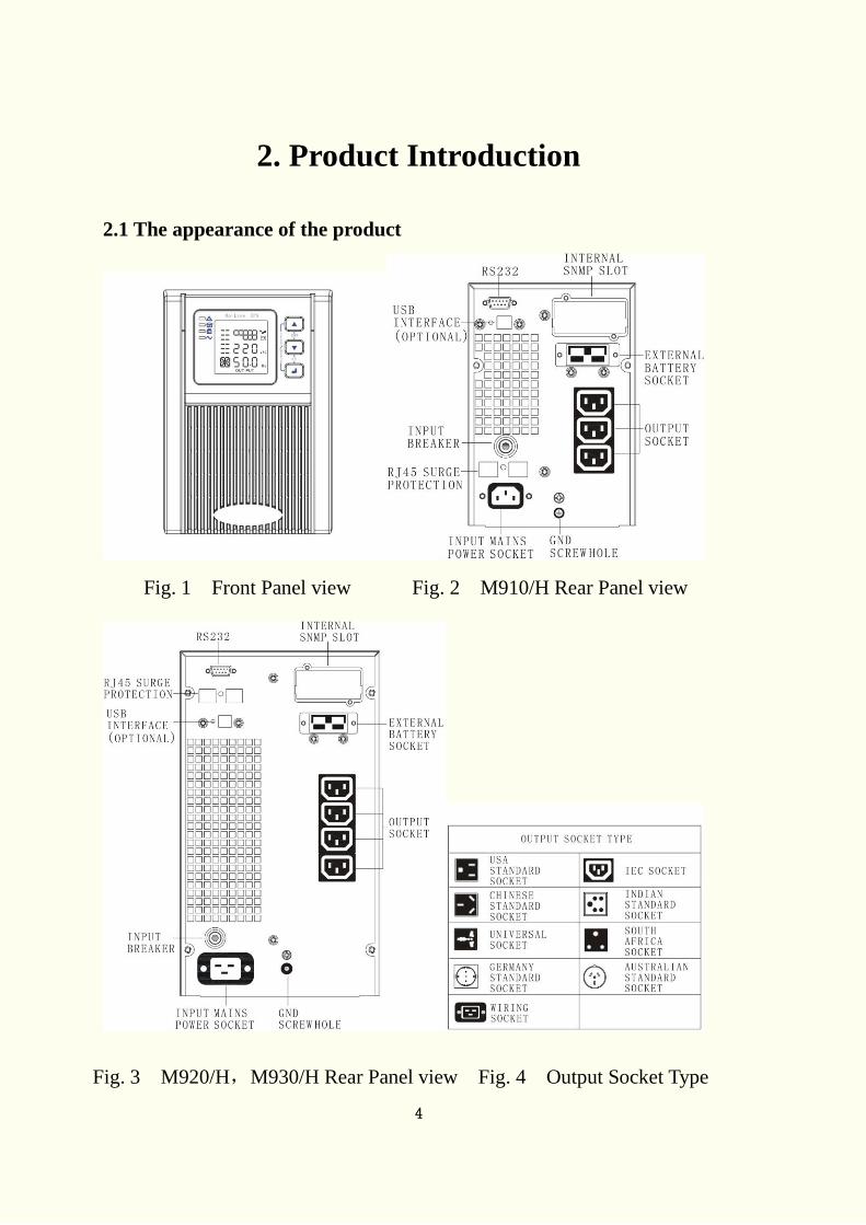
2.1 The appearance of the product
Fig. 1 Front Panel view Fig. 2 M910/H Rear Panel view
Fig. 3 M920/H,M930/H Rear Panel view Fig. 4 Output Socket Type
5
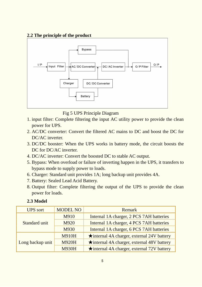
2.2 The principle of the product
Fig 5 UPS Principle Diagram
1. input filter: Complete filtering the input AC utility power to provide the clean
power for UPS.
2. AC/DC converter: Convert the filtered AC mains to DC and boost the DC for
DC/AC inverter.
3. DC/DC booster: When the UPS works in battery mode, the circuit boosts the
DC for DC/AC inverter.
4. DC/AC inverter: Convert the boosted DC to stable AC output.
5. Bypass: When overload or failure of inverting happen in the UPS, it transfers to
bypass mode to supply power to loads.
6. Charger: Standard unit provides 1A; long backup unit provides 4A.
7. Battery: Sealed Lead Acid Battery.
8. Output filter: Complete filtering the output of the UPS to provide the clean
power for loads.
2.3 Model
UPS sort MODEL NO Remark
Standard unit
M910 Internal 1A charger, 2 PCS 7AH batteries
M920 Internal 1A charger, 4 PCS 7AH batteries
M930 Internal 1A charger, 6 PCS 7AH batteries
Long backup unit
M910H ★internal 4A charger, external 24V battery
M920H ★internal 4A charger, external 48V battery
M930H ★internal 4A charger, external 72V battery
6
The 12V/9AH battery which is sealed lead acid maintenance free can be chosen
as internal battery of the standard unit.
The 7A charger can be chosen as internal charger of the long backup unit.
Two internal chargers can be used in long backup unit.
3.Installation
3.1 Unpacking and inspection
1. Unpacking the UPS and check that whether it’s damaged during the
transportation. If damaged or some parts missing, don’t start the
machine and inform the carrier and franchiser.
2. Check the annex (please consult Appendix Table 1).
3. Check if the equipment is just what you wanted to purchase. You can affirm
through inspecting the model number on back panel of the equipment.
3.2 Notes
1. Please place the UPS in a clean, stable environment, avoid the vibration, dust,
too humidity, flammable gas and liquid, corrosive.
2. The ambient temperature around UPS should keep in a range of 0℃~40℃. If
UPS works above 40℃, it is required that the rated value of the largest load
decreases 12% while the temperature increases every 5℃ . The highest
temperature cannot be more than 50℃ when UPS works.
3. UPS should be placed in a sufficiently ventilated place.
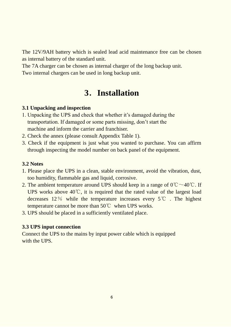
3.3 UPS input connection
Connect the UPS to the mains by input power cable which is equipped
with the UPS.
7
Fig 6 Input Connection
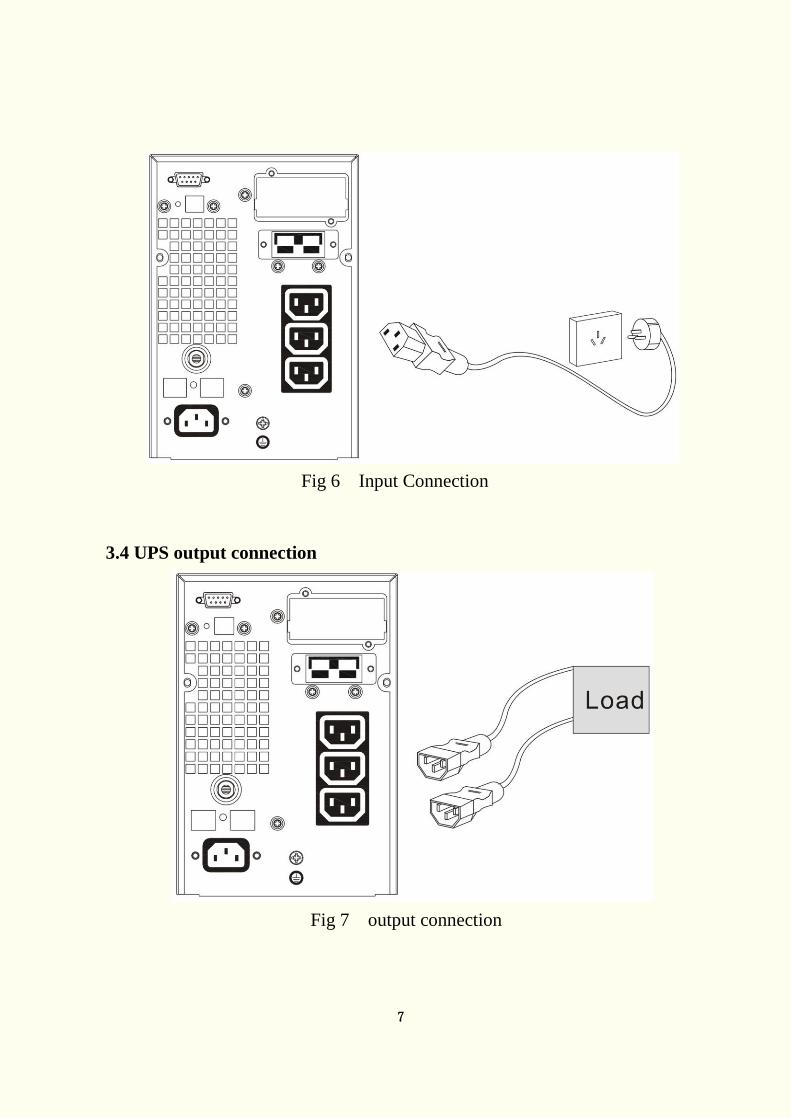
3.4 UPS output connection
Fig 7 output connection
8
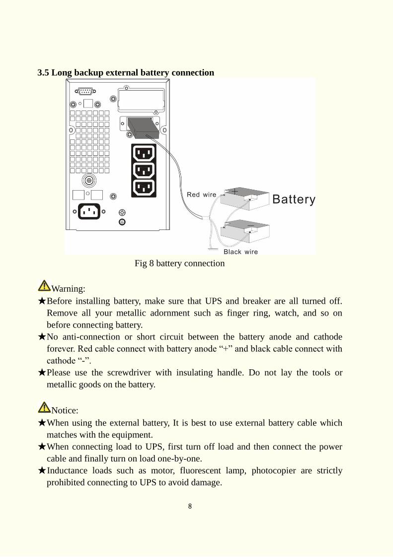
3.5 Long backup external battery connection
Fig 8 battery connection
Warning:
★Before installing battery, make sure that UPS and breaker are all turned off.
Remove all your metallic adornment such as finger ring, watch, and so on
before connecting battery.
★No anti-connection or short circuit between the battery anode and cathode
forever. Red cable connect with battery anode “+” and black cable connect with
cathode “-”.
★Please use the screwdriver with insulating handle. Do not lay the tools or
metallic goods on the battery.
Notice:
★When using the external battery, It is best to use external battery cable which
matches with the equipment.
★When connecting load to UPS, first turn off load and then connect the power
cable and finally turn on load one-by-one.
★Inductance loads such as motor, fluorescent lamp, photocopier are strictly
prohibited connecting to UPS to avoid damage.
9
★Plug UPS on the special socket with over-current protection, the power socket
that used should be connected with ground wire.
★UPS is likely to have output voltage no matter whether the power input cable is
plugged in mains input socket. If you wish UPS have no output, first break off
the switch and then cancel the mains.
★When connect laser printer, select the capacity of UPS according to the UPS
start power because the startup power is higher.
4. Panel display, operation and running
The operation is simple, operators only need to read the manual and follow the
operation instructions listed in this manual without any special training.
4.1 Faceplate display illumination
4.1.1 Keys function
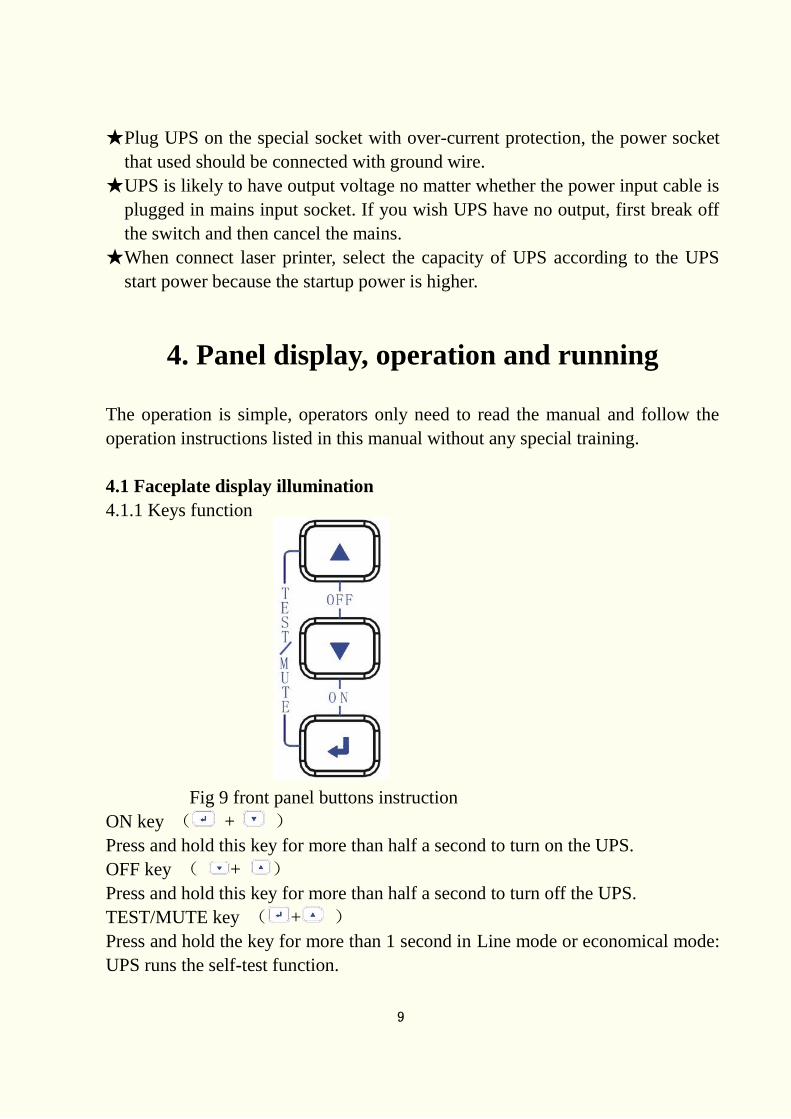
Fig 9 front panel buttons instruction
ON key ( + )
Press and hold this key for more than half a second to turn on the UPS.
OFF key ( + )
Press and hold this key for more than half a second to turn off the UPS.
TEST/MUTE key ( + )
Press and hold the key for more than 1 second in Line mode or economical mode:
UPS runs the self-test function.
10
Press and hold the key for more than 1 second in battery mode: UPS runs the
mute function.
INQUIRING key or
Non-function setting mode:
Press and hold the key for more than half a second (less than 2 seconds): Indicate
the items of the LCD item section orderly.
Press and hold this key for more than 2 seconds: Circularly and orderly display
the items every 2 seconds, when press and hold the key for some time again, it
will turn to output status.
Function setting mode:
Press and hold the key for more than half a second (less than 2 seconds): Select
the set option.
Function setting key
Non-function setting mode:
Press and hold the key for more than 2 seconds: Function setting interface.
Function setting mode:
Press and hold the key for more than half a second (less than 2 seconds): Affirm
the set option.
Press and hold the key for more than 2 seconds, exit from this function setting
interface.
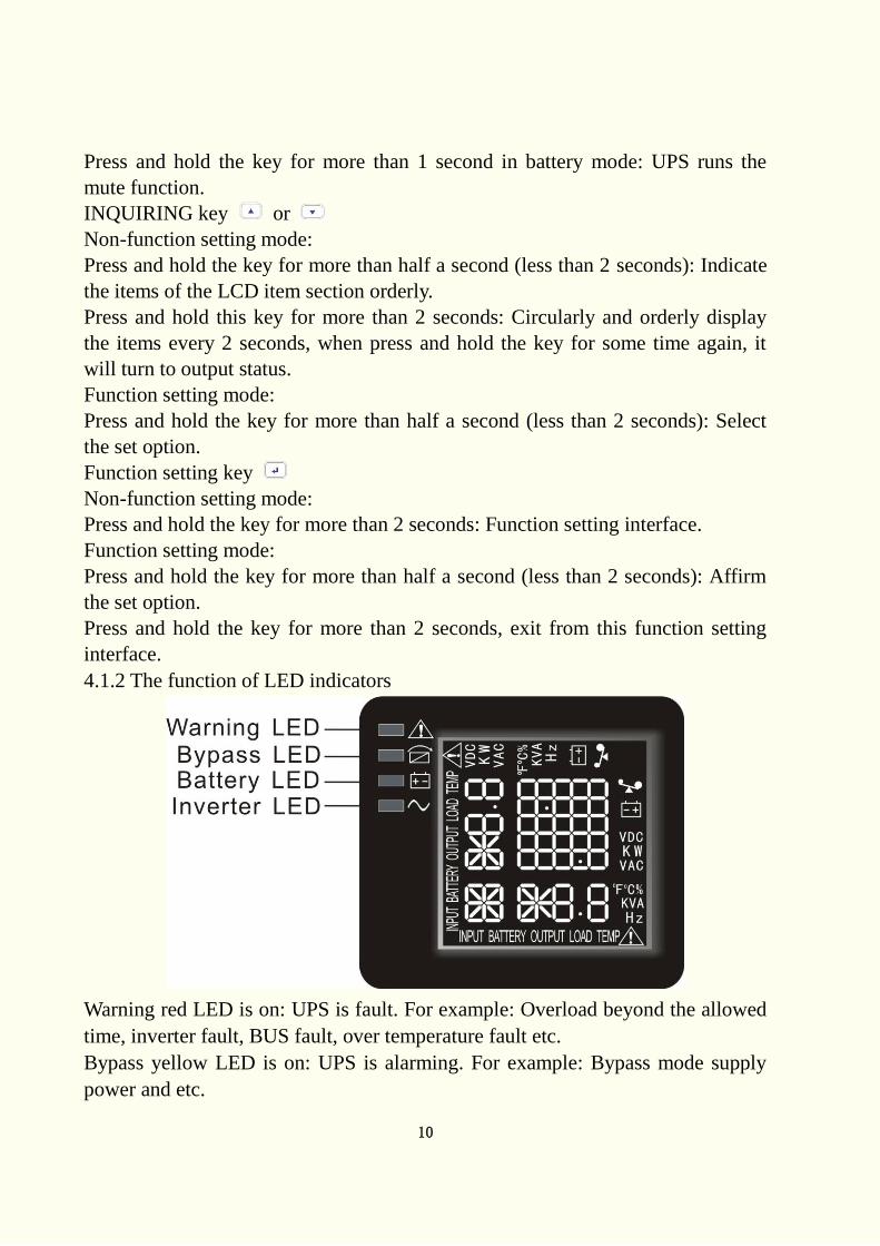
4.1.2 The function of LED indicators
Warning red LED is on: UPS is fault. For example: Overload beyond the allowed
time, inverter fault, BUS fault, over temperature fault etc.
Bypass yellow LED is on: UPS is alarming. For example: Bypass mode supply
power and etc.
11
Battery yellow LED is on: UPS is alarming. For example: Battery mode supply
power and etc.
Inverter green LED is on: UPS is normally powered by mains or ECO mode or
battery mode.
After starting the UPS, the four LEDs will light and go out one-by-one. It
circulates several times until starting the UPS successful.
NOTE: As to the LED indication in different modes, please refer to the LED
display panel and warning table.
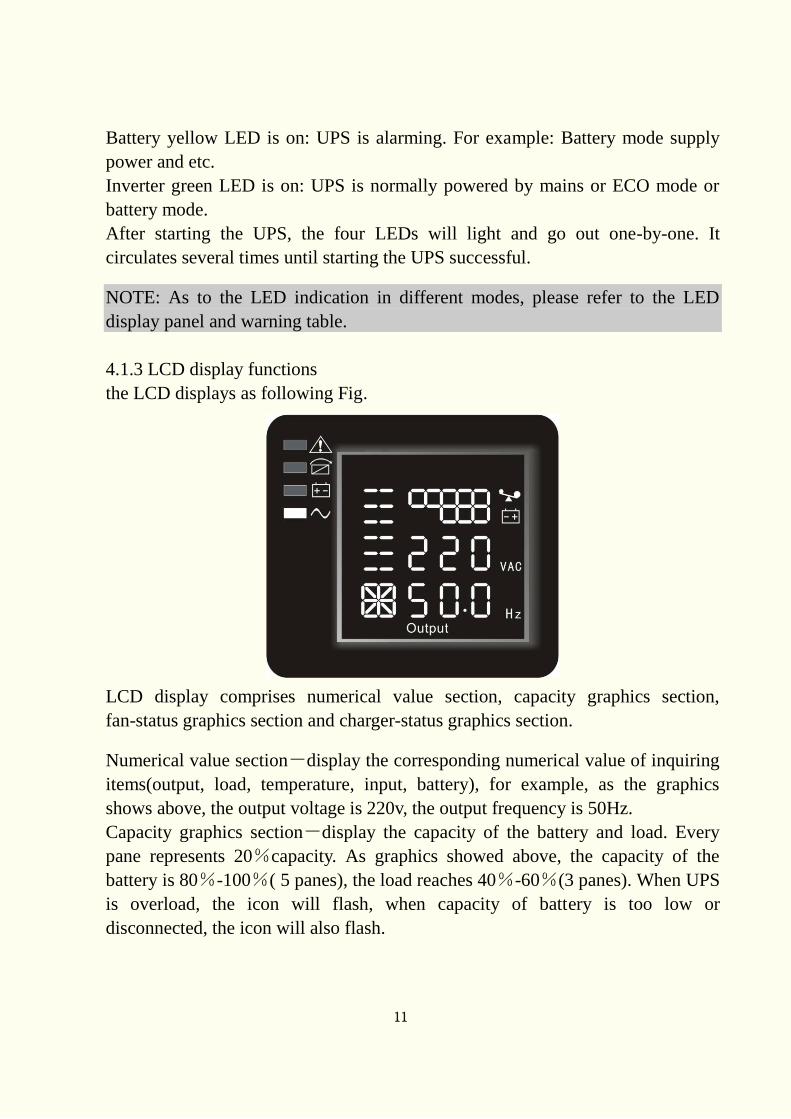
4.1.3 LCD display functions
the LCD displays as following Fig.
LCD display comprises numerical value section, capacity graphics section,
fan-status graphics section and charger-status graphics section.
Numerical value section-display the corresponding numerical value of inquiring
items(output, load, temperature, input, battery), for example, as the graphics
shows above, the output voltage is 220v, the output frequency is 50Hz.
Capacity graphics section-display the capacity of the battery and load. Every
pane represents 20%capacity. As graphics showed above, the capacity of the
battery is 80%-100%( 5 panes), the load reaches 40%-60%(3 panes). When UPS
is overload, the icon will flash, when capacity of battery is too low or
disconnected, the icon will also flash.
12
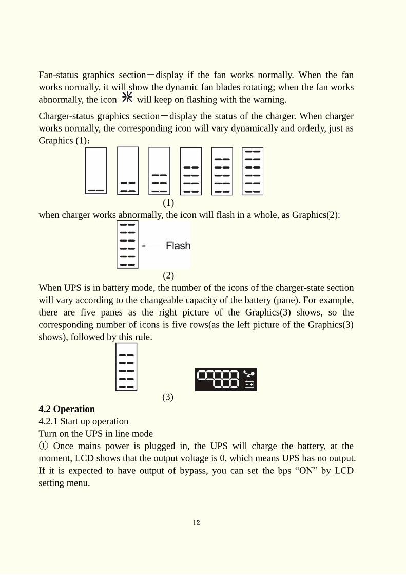
Fan-status graphics section-display if the fan works normally. When the fan
works normally, it will show the dynamic fan blades rotating; when the fan works
abnormally, the icon will keep on flashing with the warning.
Charger-status graphics section-display the status of the charger. When charger
works normally, the corresponding icon will vary dynamically and orderly, just as
Graphics (1):
(1)
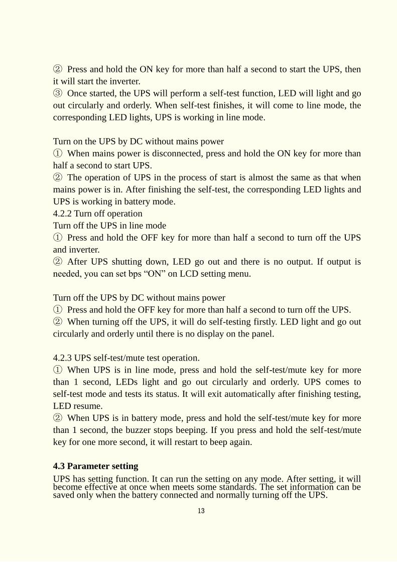
when charger works abnormally, the icon will flash in a whole, as Graphics(2):
(2)
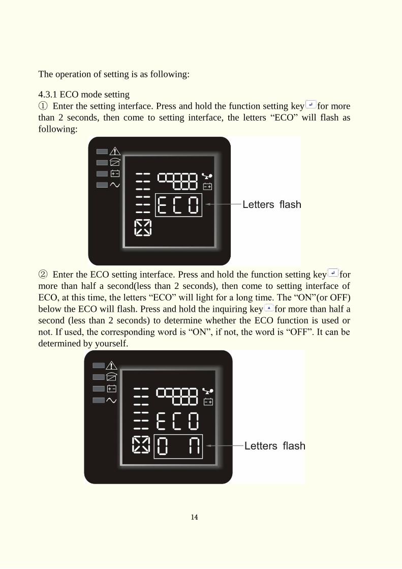
When UPS is in battery mode, the number of the icons of the charger-state section
will vary according to the changeable capacity of the battery (pane). For example,
there are five panes as the right picture of the Graphics(3) shows, so the
corresponding number of icons is five rows(as the left picture of the Graphics(3)
shows), followed by this rule.
(3)
4.2 Operation
4.2.1 Start up operation
Turn on the UPS in line mode
① Once mains power is plugged in, the UPS will charge the battery, at the
moment, LCD shows that the output voltage is 0, which means UPS has no output.
If it is expected to have output of bypass, you can set the bps “ON” by LCD
setting menu.
13
② Press and hold the ON key for more than half a second to start the UPS, then
it will start the inverter.
③ Once started, the UPS will perform a self-test function, LED will light and go
out circularly and orderly. When self-test finishes, it will come to line mode, the
corresponding LED lights, UPS is working in line mode.
Turn on the UPS by DC without mains power
① When mains power is disconnected, press and hold the ON key for more than
half a second to start UPS.
② The operation of UPS in the process of start is almost the same as that when
mains power is in. After finishing the self-test, the corresponding LED lights and
UPS is working in battery mode.
4.2.2 Turn off operation
Turn off the UPS in line mode
① Press and hold the OFF key for more than half a second to turn off the UPS
and inverter.
② After UPS shutting down, LED go out and there is no output. If output is
needed, you can set bps “ON” on LCD setting menu.
Turn off the UPS by DC without mains power
① Press and hold the OFF key for more than half a second to turn off the UPS.
② When turning off the UPS, it will do self-testing firstly. LED light and go out
circularly and orderly until there is no display on the panel.
4.2.3 UPS self-test/mute test operation.
① When UPS is in line mode, press and hold the self-test/mute key for more
than 1 second, LEDs light and go out circularly and orderly. UPS comes to
self-test mode and tests its status. It will exit automatically after finishing testing,
LED resume.
② When UPS is in battery mode, press and hold the self-test/mute key for more
than 1 second, the buzzer stops beeping. If you press and hold the self-test/mute
key for one more second, it will restart to beep again.
4.3 Parameter setting
UPS has setting function. It can run the setting on any mode. After setting, it will become effective at once when meets some standards. The set information can be saved only when the battery connected and normally turning off the UPS.
14
The operation of setting is as following:
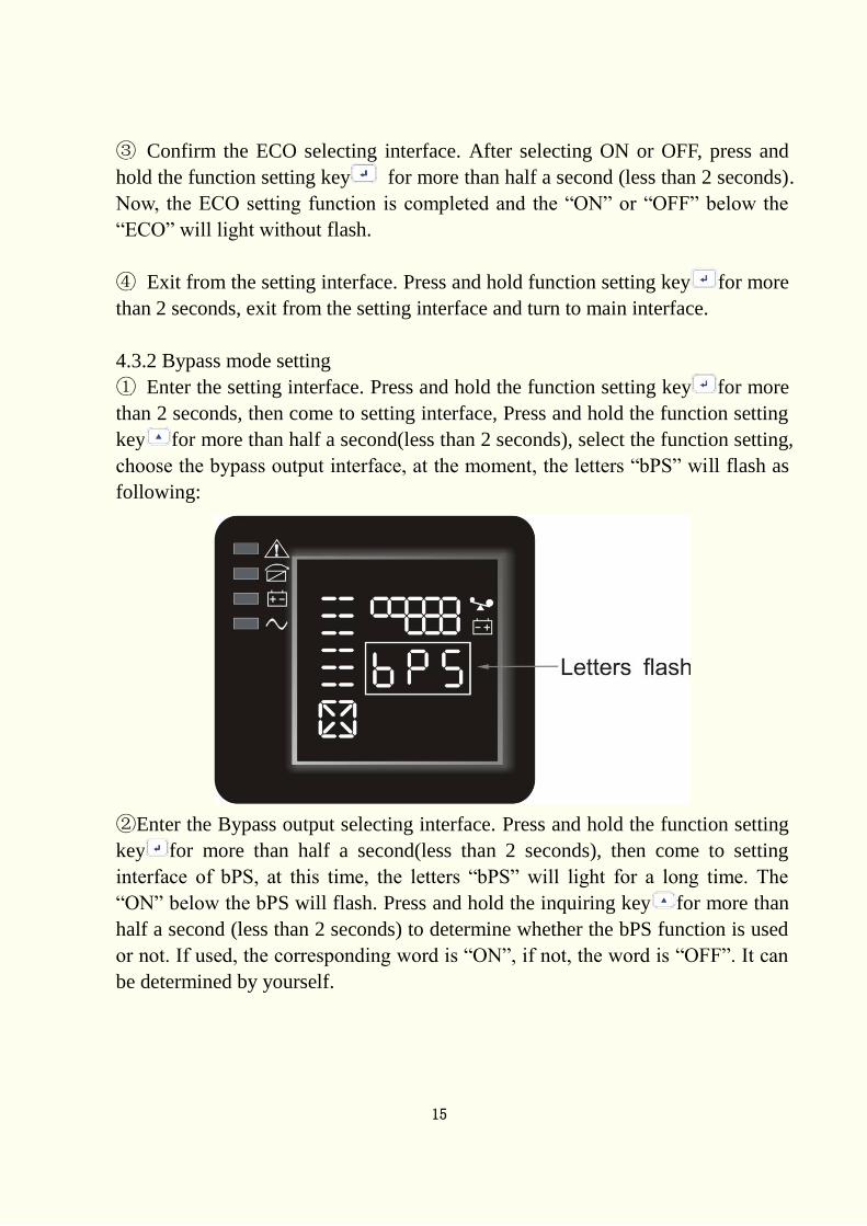
4.3.1 ECO mode setting
① Enter the setting interface. Press and hold the function setting key for more
than 2 seconds, then come to setting interface, the letters “ECO” will flash as
following:
② Enter the ECO setting interface. Press and hold the function setting key for
more than half a second(less than 2 seconds), then come to setting interface of
ECO, at this time, the letters “ECO” will light for a long time. The “ON”(or OFF)
below the ECO will flash. Press and hold the inquiring key for more than half a
second (less than 2 seconds) to determine whether the ECO function is used or
not. If used, the corresponding word is “ON”, if not, the word is “OFF”. It can be
determined by yourself.
15
③ Confirm the ECO selecting interface. After selecting ON or OFF, press and
hold the function setting key for more than half a second (less than 2 seconds).
Now, the ECO setting function is completed and the “ON” or “OFF” below the
“ECO” will light without flash.
④ Exit from the setting interface. Press and hold function setting key for more
than 2 seconds, exit from the setting interface and turn to main interface.
4.3.2 Bypass mode setting
① Enter the setting interface. Press and hold the function setting key for more
than 2 seconds, then come to setting interface, Press and hold the function setting
key for more than half a second(less than 2 seconds), select the function setting,
choose the bypass output interface, at the moment, the letters “bPS” will flash as
following:
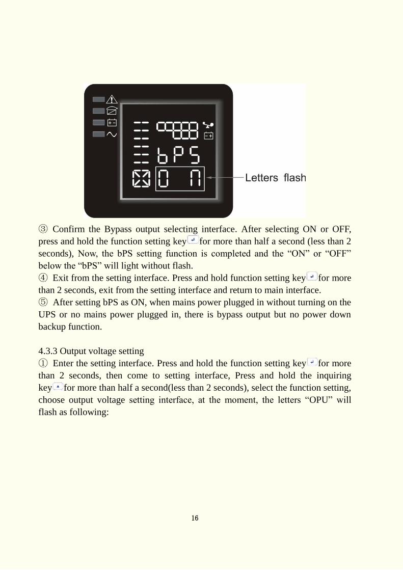
②Enter the Bypass output selecting interface. Press and hold the function setting
key for more than half a second(less than 2 seconds), then come to setting
interface of bPS, at this time, the letters “bPS” will light for a long time. The
“ON” below the bPS will flash. Press and hold the inquiring key for more than
half a second (less than 2 seconds) to determine whether the bPS function is used
or not. If used, the corresponding word is “ON”, if not, the word is “OFF”. It can
be determined by yourself.
16
③ Confirm the Bypass output selecting interface. After selecting ON or OFF,
press and hold the function setting key for more than half a second (less than 2
seconds), Now, the bPS setting function is completed and the “ON” or “OFF”
below the “bPS” will light without flash.
④ Exit from the setting interface. Press and hold function setting key for more
than 2 seconds, exit from the setting interface and return to main interface.
⑤ After setting bPS as ON, when mains power plugged in without turning on the
UPS or no mains power plugged in, there is bypass output but no power down
backup function.
4.3.3 Output voltage setting
① Enter the setting interface. Press and hold the function setting key for more
than 2 seconds, then come to setting interface, Press and hold the inquiring
key for more than half a second(less than 2 seconds), select the function setting,
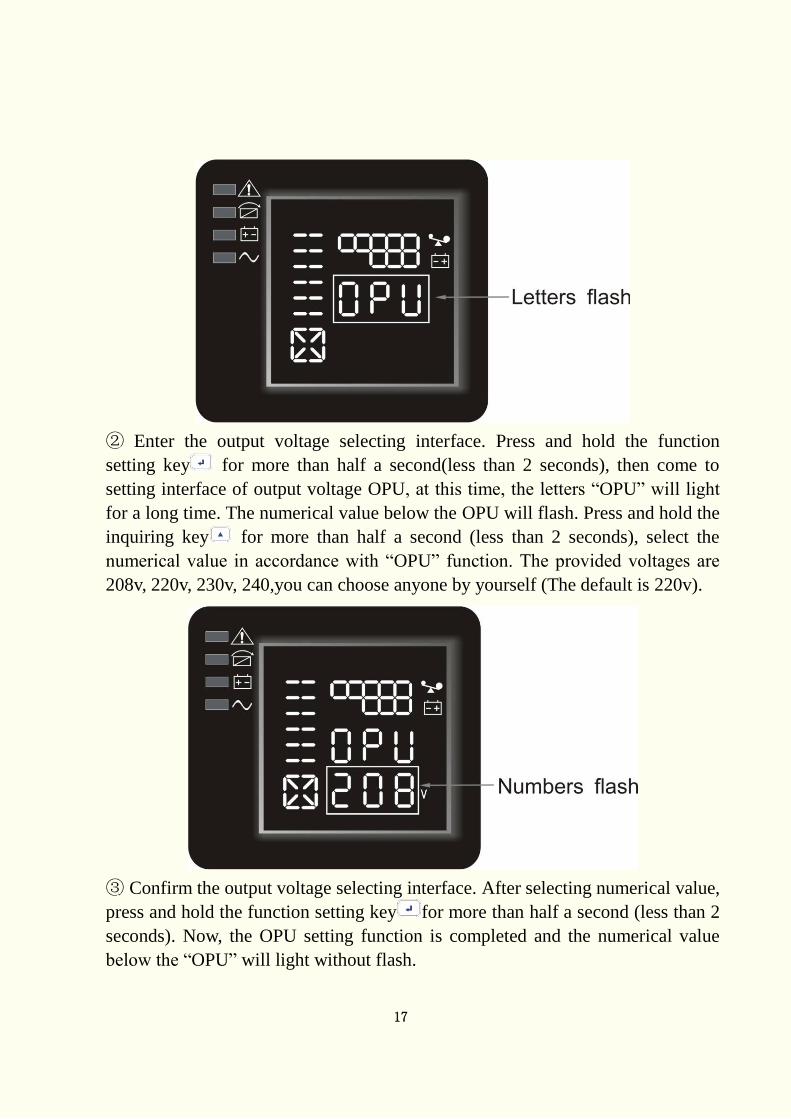
choose output voltage setting interface, at the moment, the letters “OPU” will
flash as following:
17
② Enter the output voltage selecting interface. Press and hold the function
setting key for more than half a second(less than 2 seconds), then come to
setting interface of output voltage OPU, at this time, the letters “OPU” will light
for a long time. The numerical value below the OPU will flash. Press and hold the
inquiring key for more than half a second (less than 2 seconds), select the
numerical value in accordance with “OPU” function. The provided voltages are
208v, 220v, 230v, 240,you can choose anyone by yourself (The default is 220v).
③ Confirm the output voltage selecting interface. After selecting numerical value,
press and hold the function setting key for more than half a second (less than 2
seconds). Now, the OPU setting function is completed and the numerical value
below the “OPU” will light without flash.
18
④ Exit from the setting interface. Press and hold function setting key for more
than half a second (less than 2 seconds), exit from the setting interface and return
to main interface.
NOTE:
When setting the output voltage, you’d better cut off the load of the UPS first.
4.4 Parameters inquiring
Press and hold the inquiring key or for more than half a second(less than 2
seconds) to inquire about items. The inquired items include input, battery, output,
load, temperature. The displayed items on LCD screen are showed as following:
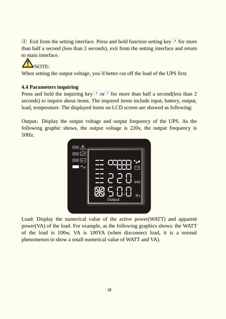
Output:Display the output voltage and output frequency of the UPS. As the
following graphic shows, the output voltage is 220v, the output frequency is
50Hz.
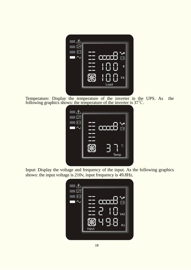
Load: Display the numerical value of the active power(WATT) and apparent
power(VA) of the load. For example, as the following graphics shows: the WATT
of the load is 100w, VA is 100VA (when disconnect load, it is a normal
phenomenon to show a small numerical value of WATT and VA).
19
Temperature: Display the temperature of the inverter in the UPS. As the following graphics shows: the temperature of the inverter is 37℃.
Input: Display the voltage and frequency of the input. As the following graphics
shows: the input voltage is 210v, input frequency is 49.8Hz.
20
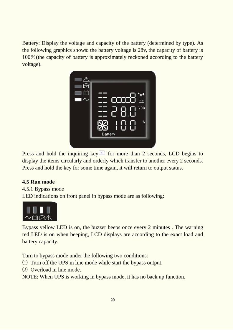
Battery: Display the voltage and capacity of the battery (determined by type). As
the following graphics shows: the battery voltage is 28v, the capacity of battery is
100%(the capacity of battery is approximately reckoned according to the battery
voltage).
Press and hold the inquiring key for more than 2 seconds, LCD begins to
display the items circularly and orderly which transfer to another every 2 seconds.
Press and hold the key for some time again, it will return to output status.
4.5 Run mode
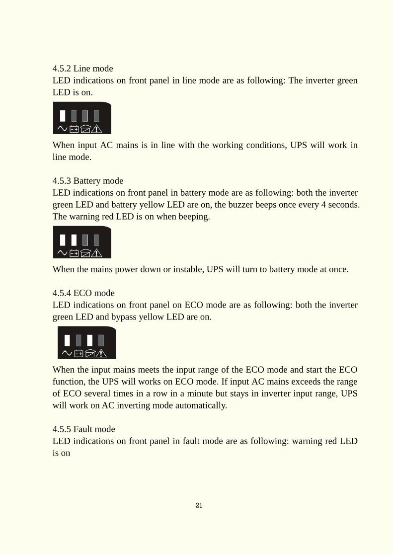
4.5.1 Bypass mode
LED indications on front panel in bypass mode are as following:
Bypass yellow LED is on, the buzzer beeps once every 2 minutes . The warning
red LED is on when beeping, LCD displays are according to the exact load and
battery capacity.
Turn to bypass mode under the following two conditions:
① Turn off the UPS in line mode while start the bypass output.
② Overload in line mode.
NOTE: When UPS is working in bypass mode, it has no back up function.
21
4.5.2 Line mode
LED indications on front panel in line mode are as following: The inverter green
LED is on.
When input AC mains is in line with the working conditions, UPS will work in
line mode.
4.5.3 Battery mode
LED indications on front panel in battery mode are as following: both the inverter
green LED and battery yellow LED are on, the buzzer beeps once every 4 seconds.
The warning red LED is on when beeping.
When the mains power down or instable, UPS will turn to battery mode at once.
4.5.4 ECO mode
LED indications on front panel on ECO mode are as following: both the inverter
green LED and bypass yellow LED are on.
When the input mains meets the input range of the ECO mode and start the ECO
function, the UPS will works on ECO mode. If input AC mains exceeds the range
of ECO several times in a row in a minute but stays in inverter input range, UPS
will work on AC inverting mode automatically.
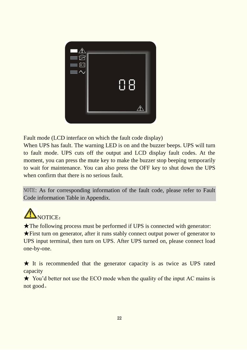
4.5.5 Fault mode
LED indications on front panel in fault mode are as following: warning red LED
is on
22
Fault mode (LCD interface on which the fault code display)
When UPS has fault. The warning LED is on and the buzzer beeps. UPS will turn
to fault mode. UPS cuts off the output and LCD display fault codes. At the
moment, you can press the mute key to make the buzzer stop beeping temporarily
to wait for maintenance. You can also press the OFF key to shut down the UPS
when confirm that there is no serious fault.
NOTE: As for corresponding information of the fault code, please refer to Fault
Code information Table in Appendix.
NOTICE:
★The following process must be performed if UPS is connected with generator:
★First turn on generator, after it runs stably connect output power of generator to
UPS input terminal, then turn on UPS. After UPS turned on, please connect load
one-by-one.
★ It is recommended that the generator capacity is as twice as UPS rated
capacity
★ You’d better not use the ECO mode when the quality of the input AC mains is
not good。
23
5. Maintenance Only minimum maintenance is required for this series of UPS. The battery is
sealed lead acid maintenance free. It only needs to be kept charging to obtain the
expected life. Whether it is started or not, the UPS would charge batteries once it
is connected to mains and provide protection for over-charging and deep
discharging.
5.1 Battery maintenance
1 It is recommended that the batteries are manually charged or discharged
once every three or four months if UPS has not been used for a long time or the
power is long-term uninterruptible. The battery will be fully discharge to
low-voltage protection shutdown. Then it needs to be fully charged once.
2. In high temperature area, batteries should be manually charged and discharged
once every two months. The process is the same as that said above.
3. Under normal circumstances of using, the battery working life is three to five
years. If you find that the battery do not act well such as obviously shortening
of backup time, too much imbalance on battery voltage so on, the battery
should be replaced as soon as possible, which must be performed by qualified
personnel.
4. When replace battery, it is recommended to change battery all together instead
of changing separately.
NOTICE:
★Before replacing batteries, first please turn off the UPS and break off the mains.
Remove your metallic adornment such as finger ring, watch and so on.
★When replace batteries, please use the screwdriver with insulating handle. Do
not lay the tools or metallic goods on the battery.
★Never reverse or short circuit between the battery anode and cathode.
24
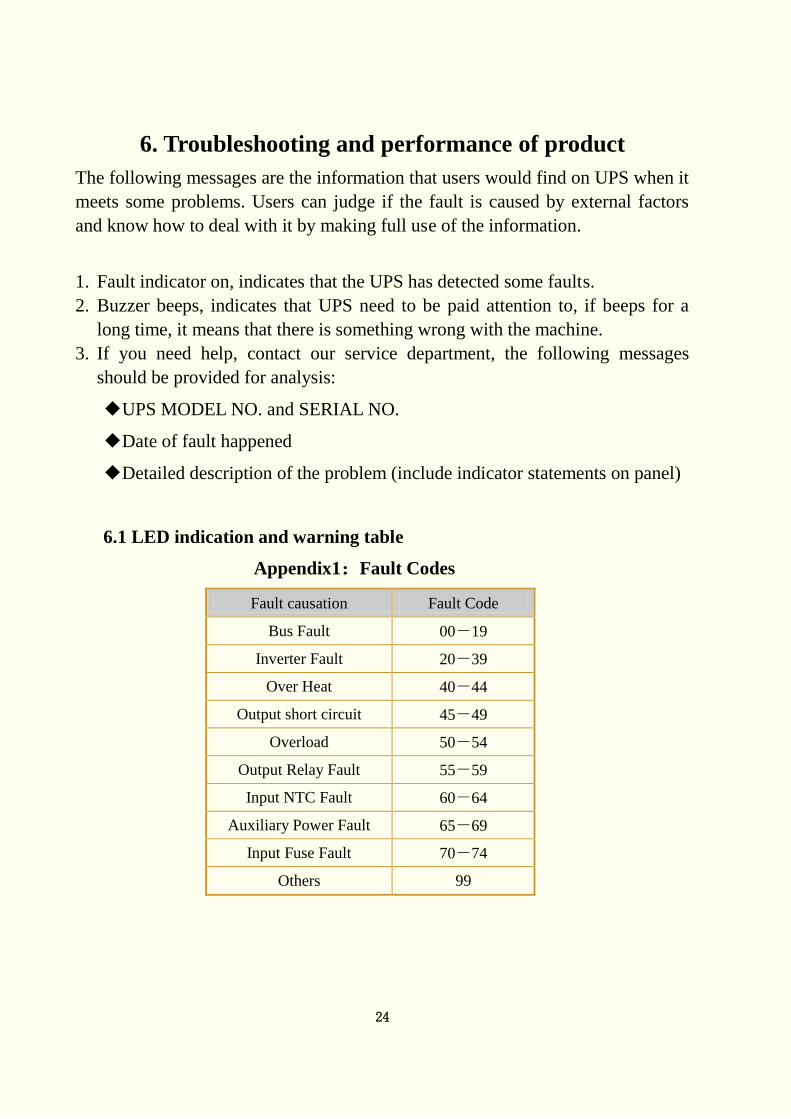
6. Troubleshooting and performance of product
The following messages are the information that users would find on UPS when it
meets some problems. Users can judge if the fault is caused by external factors
and know how to deal with it by making full use of the information.
1. Fault indicator on, indicates that the UPS has detected some faults.
2. Buzzer beeps, indicates that UPS need to be paid attention to, if beeps for a
long time, it means that there is something wrong with the machine.
3. If you need help, contact our service department, the following messages
should be provided for analysis:
◆UPS MODEL NO. and SERIAL NO.
◆Date of fault happened
◆Detailed description of the problem (include indicator statements on panel)
6.1 LED indication and warning table
Appendix1:Fault Codes
Fault causation Fault Code
Bus Fault 00-19
Inverter Fault 20-39
Over Heat 40-44
Output short circuit 45-49
Overload 50-54
Output Relay Fault 55-59
Input NTC Fault 60-64
Auxiliary Power Fault 65-69
Input Fuse Fault 70-74
Others 99
25
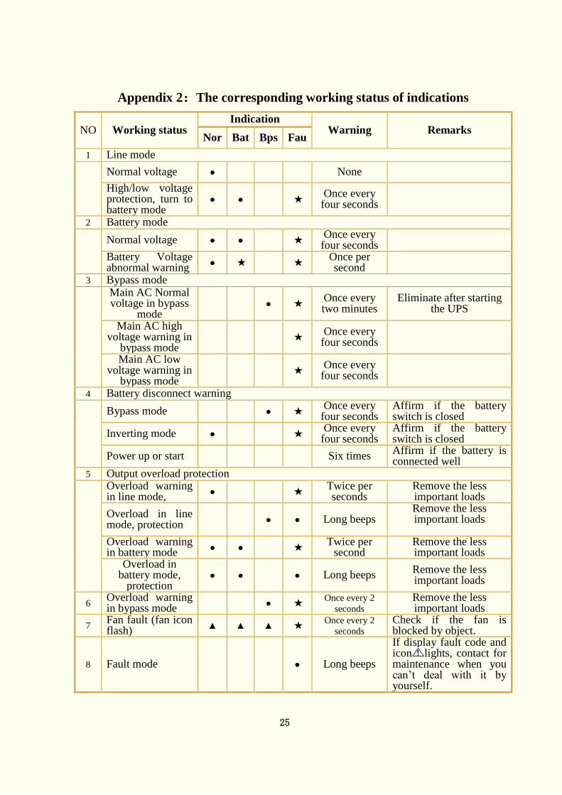
Appendix 2:The corresponding working status of indications
NO Working status
Indication
Warning Remarks Nor Bat Bps Fau
1 Line mode
Normal voltage ● None
High/low voltage protection, turn to battery mode
● ● ★ Once every
four seconds
2 Battery mode
Normal voltage ● ● ★ Once every
four seconds
Battery Voltage abnormal warning
● ★
★ Once per second
3 Bypass mode
Main AC Normal voltage in bypass
mode
● ★ Once every two minutes
Eliminate after starting the UPS
Main AC high voltage warning in
bypass mode
★ Once every
four seconds
Main AC low voltage warning in
bypass mode
★ Once every
four seconds
4 Battery disconnect warning
Bypass mode ● ★ Once every
four seconds
Affirm if the battery switch is closed
Inverting mode ● ★ Once every
four seconds
Affirm if the battery switch is closed
Power up or start Six times Affirm if the battery is connected well
5 Output overload protection
Overload warning in line mode,
● ★ Twice per seconds
Remove the less important loads
Overload in line mode, protection
● ● Long beeps
Remove the less important loads
Overload warning in battery mode
● ● ★ Twice per
second
Remove the less important loads
Overload in battery mode,
protection
● ● ● Long beeps Remove the less important loads
6 Overload warning in bypass mode
● ★ Once every 2
seconds
Remove the less important loads
7 Fan fault (fan icon flash)
▲ ▲ ▲ ★ Once every 2
seconds
Check if the fan is blocked by object.
8 Fault mode ● Long beeps
If display fault code and icon lights, contact for maintenance when you can’t deal with it by yourself.
26
● _indicator lights for a long time
★ _indicator flashes
▲ _the status of indicator depends on other conditions
NOTE: When UPS has fault, it is convenient for you to know the working status
of UPS and the exact information about the fault promptly by referring to the two
tables listed above.
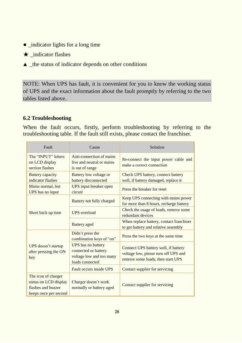
6.2 Troubleshooting
When the fault occurs, firstly, perform troubleshooting by referring to the
troubleshooting table. If the fault still exists, please contact the franchiser.
Fault Cause Solution
The “INPUT” letters
on LCD display
section flashes
Anti-connection of mains
live and neutral or mains
is out of range
Re-connect the input power cable and
make a correct connection
Battery capacity
indicator flashes
Battery low voltage or
battery disconnected
Check UPS battery, connect battery
well, if battery damaged, replace it
Mains normal, but
UPS has no input
UPS input breaker open
circuit Press the breaker for reset
Short back up time
Battery not fully charged Keep UPS connecting with mains power
for more than 8 hours, recharge battery
UPS overload Check the usage of loads, remove some
redundant devices
Battery aged When replace battery, contact franchiser
to get battery and relative assembly
UPS doesn’t startup
after pressing the ON
key
Didn’t press the
combination keys of “on” Press the two keys at the same time
UPS has no battery
connected or battery
voltage low and too many
loads connected
Connect UPS battery well, if battery
voltage low, please turn off UPS and
remove some loads, then start UPS
Fault occurs inside UPS Contact supplier for servicing
The icon of charger
status on LCD display
flashes and buzzer
beeps once per second
Charger doesn’t work
normally or battery aged Contact supplier for servicing
27
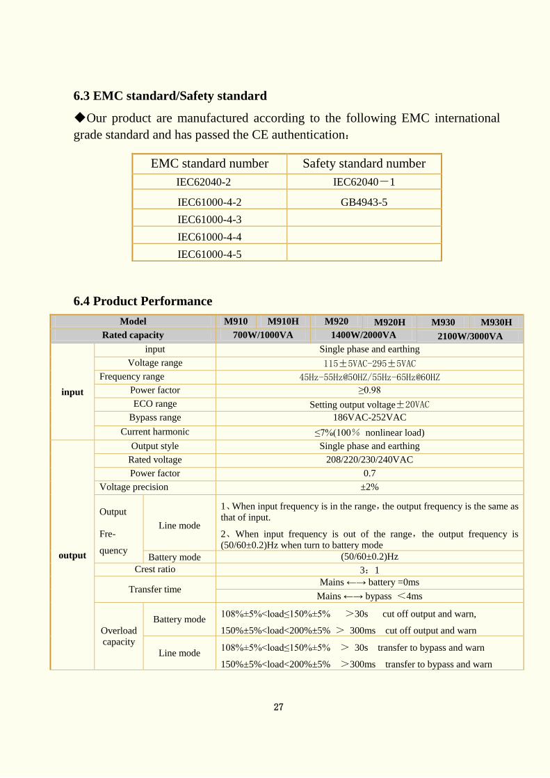
6.3 EMC standard/Safety standard
◆Our product are manufactured according to the following EMC international
grade standard and has passed the CE authentication:
6.4 Product Performance
Model M910 M910H M920 M920H M930 M930H
Rated capacity 700W/1000VA 1400W/2000VA 2100W/3000VA
input
input Single phase and earthing
Voltage range 115±5VAC-295±5VAC
Frequency range 45Hz-55Hz@50HZ/55Hz-65Hz@60HZ
Power factor ≥0.98
ECO range Setting output voltage±20VAC
Bypass range 186VAC-252VAC
Current harmonic ≤7%(100% nonlinear load)
output
Output style Single phase and earthing
Rated voltage 208/220/230/240VAC
Power factor 0.7
Voltage precision ±2%
Output
Fre-
quency
Line mode
1、When input frequency is in the range,the output frequency is the same as
that of input.
2、When input frequency is out of the range,the output frequency is
(50/60±0.2)Hz when turn to battery mode
Battery mode (50/60±0.2)Hz
Crest ratio 3:1
Transfer time Mains ←→ battery =0ms
Mains ←→ bypass <4ms
Overload
capacity
Battery mode 108%±5%<load≤150%±5% >30s cut off output and warn,
150%±5%<load<200%±5% > 300ms cut off output and warn
Line mode 108%±5%<load≤150%±5% > 30s transfer to bypass and warn
150%±5%<load<200%±5% >300ms transfer to bypass and warn
EMC standard number Safety standard number
IEC62040-2 IEC62040-1
IEC61000-4-2 GB4943-5
IEC61000-4-3
IEC61000-4-4
IEC61000-4-5
28
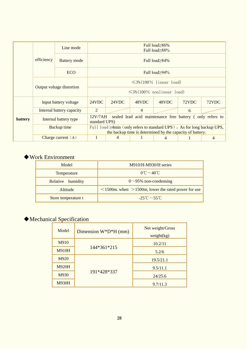
efficiency
Line mode Full load≥86%
Full load≥88%
Battery mode Full load≥84%
ECO Full load≥94%
Output voltage distortion ≤3%(100% linear load)
≤5%(100% nonlinear load)
battery
Input battery voltage 24VDC 24VDC 48VDC 48VDC 72VDC 72VDC
Internal battery capacity 2 4 6
Internal battery type 12V/7AH sealed lead acid maintenance free battery ( only refers to
standard UPS)
Backup time Full load ≥4min(only refers to standard UPS),As for long backup UPS,
the backup time is determined by the capacity of battery.
Charge current(A) 1 4 1 4 1 4
◆ Work Environment
Model M910/H-M930/H series
Temperature 0℃~40℃
Relative humidity
humidity humidityu humidity
0~95% non-condensing
Altitude <1500m. when >1500m, lower the rated power for use
Store temperature t -25℃~55℃
◆ Mechanical Specification
Model Dimension W*D*H (mm) Net weight/Gross
weight(kg)
M910
144*361*215 10.2/11
M910H 5.2/6
M920
191*428*337
19.5/21.1
M920H 9.5/11.1
M930 24/25.6
M930H 9.7/11.3
29
6.5 Communication interface
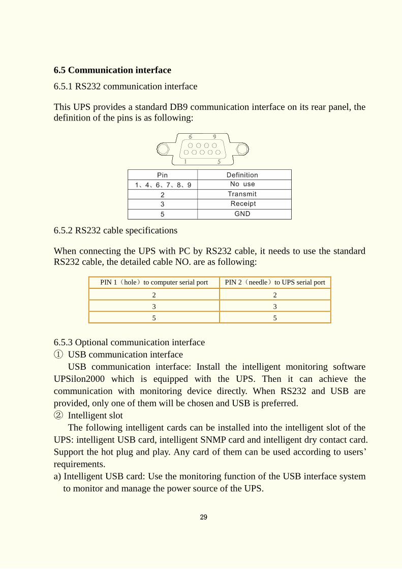
6.5.1 RS232 communication interface
This UPS provides a standard DB9 communication interface on its rear panel, the
definition of the pins is as following:
6.5.2 RS232 cable specifications
When connecting the UPS with PC by RS232 cable, it needs to use the standard
RS232 cable, the detailed cable NO. are as following:
PIN 1(hole)to computer serial port PIN 2(needle)to UPS serial port
2 2
3 3
5 5
6.5.3 Optional communication interface
① USB communication interface
USB communication interface: Install the intelligent monitoring software
UPSilon2000 which is equipped with the UPS. Then it can achieve the
communication with monitoring device directly. When RS232 and USB are
provided, only one of them will be chosen and USB is preferred.
② Intelligent slot
The following intelligent cards can be installed into the intelligent slot of the
UPS: intelligent USB card, intelligent SNMP card and intelligent dry contact card.
Support the hot plug and play. Any card of them can be used according to users’
requirements.
a) Intelligent USB card: Use the monitoring function of the USB interface system
to monitor and manage the power source of the UPS.
30
b) Intelligent SNMP card: When connecting to the internet by SNMP card, it
communications with the monitoring computer to monitor power source of the
UPS from far end.
c) Intelligent dry contact card: Use the monitoring function of the dry contact
interface system to monitor and manage the power source of the UPS.
NOTE: Remove the cover before installing the optional accessories.
Intelligent Slot can be used together with RS232.
The operating instruction of the UPSilon2000 can be acquired from the CD.
As for the operating instructions of the intelligent USB card, SNMP card and dry
contact card, please refer to the relative special instructions.