Embed Size (px)
Citation preview
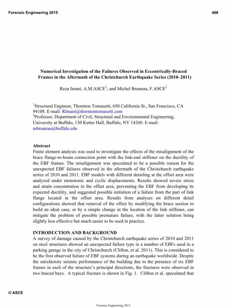
Numerical Investigation of the Failures Observed in Eccentrically Braced Frames in the Aftermath of Christchurch Earthquake Series (2010–2011)
Reza Imani, A.M.ASCE1; and Michel Bruneau, F.ASCE2
1Structural Engineer, Thornton Tomasetti, 650 California St., San Francisco, CA 94108. E-mail: [email protected] 2Professor, Department of Civil, Structural and Environmental Engineering, University at Buffalo, 130 Ketter Hall, Buffalo, NY 14260. E-mail: [email protected] Abstract Finite element analysis was used to investigate the effects of the misalignment of the brace flange-to-beam connection point with the link-end stiffener on the ductility of the EBF frames. The misalignment was speculated to be a possible reason for the unexpected EBF failures observed in the aftermath of the Christchurch earthquake series of 2010 and 2011. EBF models with different detailing at the offset area were analyzed under monotonic and cyclic displacements. Results showed severe stress and strain concentration in the offset area, preventing the EBF from developing its expected ductility, and suggested possible initiation of a failure from the part of link flange located in the offset area. Results from analyses on different detail configurations showed that removal of the offset by modifying the brace section to build an ideal case, or by a simple change in the location of the link stiffener, can mitigate the problem of possible premature failure, with the latter solution being slightly less effective but much easier to be used in practice. INTRODUCTION AND BACKGROUND A survey of damage caused by the Christchurch earthquake series of 2010 and 2011 on steel structures showed an unexpected failure type in a number of EBFs used in a parking garage in the city of Christchurch (Clifton, et al. 2011). This is considered to be the first observed failure of EBF systems during an earthquake worldwide. Despite the satisfactory seismic performance of the building due to the presence of six EBF frames in each of the structure’s principal directions, the fractures were observed in two braced bays. A typical fracture is shown in Fig. 1. Clifton et al. speculated that
Forensic Engineering 2015 468
© ASCE
Forensic Engineering 2015
the factstifin c
Fig
The(20to deftestfinistrubetwAccbuiandet aEBbratresThifact COFouthiscyc
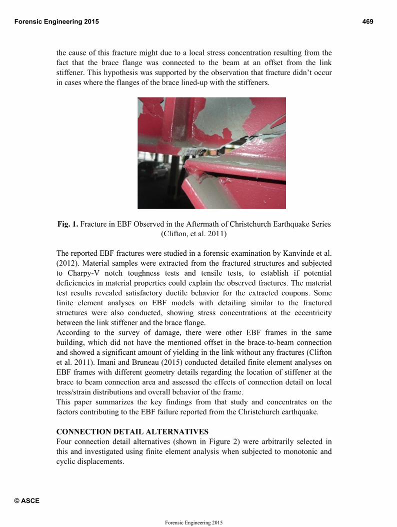
cause of thit that the b
ffener. This hcases where
g. 1. Fracture
e reported E012). Materia
Charpy-V ficiencies in t results revite element uctures wereween the lincording to lding, which
d showed a sal. 2011). ImF frames wice to beam ss/strain distris paper sumtors contribu
ONNECTIOur connectios and investiclic displacem
is fracture mbrace flange hypothesis wthe flanges o
e in EBF Ob
BF fracturesal samples wnotch toughmaterial pro
vealed satisfanalyses o
e also condnk stiffener athe survey h did not hasignificant am
mani and Bruith different connection ributions andmmarizes thuting to the E
ON DETAILon detail alteigated usingments.
might due towas conne
was supporteof the brace
bserved in th(Clifto
s were studiewere extracthness tests operties coulfactory duction EBF moducted, showand the brace
of damage,ave the menmount of yieuneau (2015)
geometry darea and assd overall beh
he key findiEBF failure r
L ALTERNAernatives (sh
g finite elem
a local streected to the ed by the oblined-up wit
e Aftermathon, et al. 201
ed in a forened from theand tensil
ld explain thile behavior
odels with dwing stress e flange. , there were
ntioned offseelding in the) conducted
details regardsessed the efhavior of theings from threported from
ATIVES hown in Fig
ment analysis
ess concentrabeam at a
bservation thth the stiffen
h of Christch11)
nsic examinae fractured ste tests, to he observed r for the extdetailing simconcentratio
e other EBFet in the brae link withou
detailed finding the locffects of cone frame. hat study anm the Christ
gure 2) weres when subje
ation resultinan offset frohat fracture dners.
hurch Earthqu
ation by Kantructures anestablish i
fractures. Ttracted coupmilar to thons at the
F frames inace-to-beam ut any fractunite element ation of stifnnection det
nd concentrtchurch earth
e arbitrarily ected to mon
ng from theom the link didn’t occur
uake Series
nvinde et al. nd subjected if potential
The material pons. Some
he fractured eccentricity
n the same connection
ures (Clifton analyses on
ffener at the tail on local
ates on the hquake.
selected in notonic and
Forensic Engineering 2015 469
© ASCE
Forensic Engineering 2015
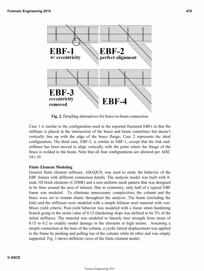
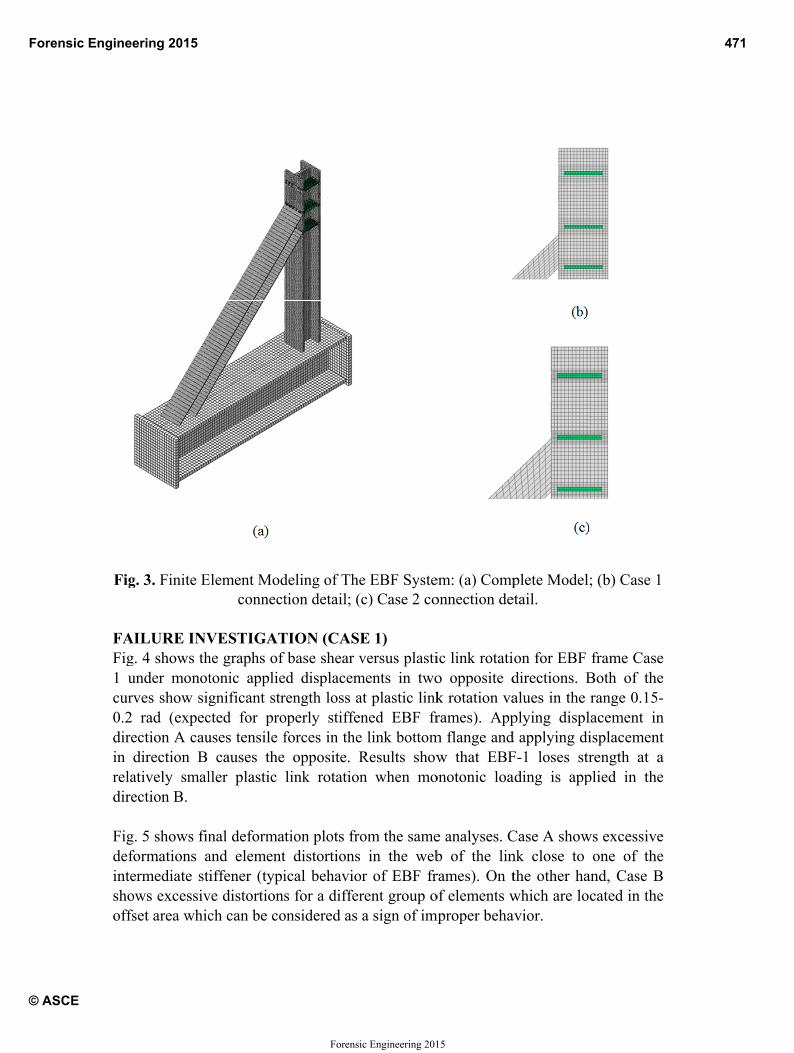
Casstifverconstifbra341 FinGenEBnodto bframbralinkMisbrainit0.1simto tsup
F
se 1 is similffener is placrtically line nfiguration; ffener has bece is welded
1-10.
nite Elementneral finite F frames wi
de 3D brick be finer aroume was moce were setk) and the stses yield crinch going totial stiffness5 to 0.2 to
mple connectthe frame bypported. Fig.
ig. 2. Detail
ar to the conced at the inup with theThe third caeen moved d to the beam
t Modeling element sofith differentelements (Cund the areadeled. To
t to remain tiffeners weriteria. Post-yo the strain v). The matecrudely moion at the ba
y pushing an3 shows dif
ing alternati
nfiguration untersection oe edge of tase, EBF-3, to align verm. Note that
ftware, ABAt connection
C3D8R) and a of interest.eliminate uelastic throure modeled yield behavivalue of 0.15erial was model damage
ase of the cold pulling top
fferent views
ves for brac
used in the rof the bracethe brace flais similar to
rtically with t all four co
AQUS, was details. Thea non-unifo Due to sym
unnecessary ughout the awith a simpor was mod5 (hardeningodeled to lin
in the elemlumn, a cyclp of the colus of the finite
e-to-beam c
reported frace and beam ange; Case o EBF-1, exthe point w
onfigurations
used to stue analysis m
orm mesh pammetry, onlycomplexitieanalysis. Th
ple bilinear sdeled with a g slope was dnearly lose
ments at highlic lateral disumn while ite element m
onnection
ctured EBFscenterlines 2 represent
xcept that thwhere the flas are allowed
udy the behamodel was battern that wy half of a tes, the columhe beam (insteel materia
linear straindefined to bstrength froh strains. Asplacement wts other end
model.
s in that the but doesn’t ts the ideal he link end-ange of the d per AISC
avior of the uilt with 8-as designed typical EBF mn and the
ncluding the al with von-n hardening e 3% of the m strain of
Assuming a was applied was simply
f
Forensic Engineering 2015 470
© ASCE
Forensic Engineering 2015
Fig
FAFig1 ucur0.2 direin reladire Figdefinteshooffs
g. 3. Finite E
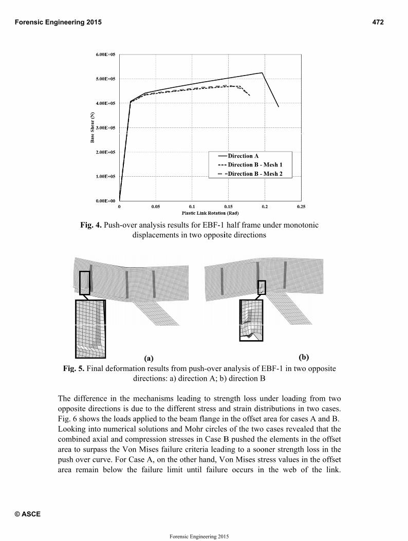
AILURE INVg. 4 shows thunder monotrves show sig
rad (expecection A caudirection B atively smalection B.
g. 5 shows finformations aermediate stows excessivset area whic
Element Modconnect
VESTIGAThe graphs of tonic appliegnificant strcted for prouses tensile f
causes the ller plastic
nal deformatand elementiffener (typi
ve distortionsch can be co
deling of Thetion detail; (
TION (CASEbase shear v
ed displacemrength loss aoperly stiffenforces in the
opposite. Rlink rotation
tion plots frot distortions ical behavios for a differ
onsidered as
e EBF Systec) Case 2 co
E 1) versus plasti
ments in twoat plastic linkned EBF fr
e link bottomResults shown when mo
om the samein the web
or of EBF frrent group oa sign of im
em: (a) Componnection de
ic link rotatio opposite dk rotation varames). App
m flange andw that EBF
onotonic loa
e analyses. Cb of the linrames). On tof elements w
mproper beha
plete Modeletail.
ion for EBF directions. Balues in the plying displd applying diF-1 loses strading is app
Case A shownk close to the other hawhich are loavior.
; (b) Case 1
frame Case Both of the range 0.15-
lacement in isplacement rength at a
plied in the
ws excessive one of the
and, Case B cated in the
Forensic Engineering 2015 471
© ASCE
Forensic Engineering 2015
Fi
TheoppFigLoocomareapusarea
Fig. 4. P
ig. 5. Final d
e difference posite directig. 6 shows thoking into nmbined axiala to surpass sh over curvea remain be
Push-over andispl
deformation direc
in the mecions is due t
he loads applumerical soll and comprethe Von M
e. For Case elow the fa
nalysis resultlacements in
results fromctions: a) dir
hanisms leato the differlied to the belutions and Mession stressises failure cA, on the ot
ailure limit
ts for EBF-1 n two opposi
m push-over arection A; b)
ading to streent stress aneam flange inMohr circlesses in Case Bcriteria leadther hand, Vuntil failure
half frame uite directions
analysis of E) direction B
ength loss und strain disn the offset as of the two B pushed th
ding to a sooVon Mises str
e occurs in
under monots
EBF-1 in twoB
under loadingtributions inarea for case cases reveae elements i
oner strengthress values i
n the web o
tonic
o opposite
g from two n two cases. es A and B.aled that the in the offset h loss in the in the offset of the link.
Forensic Engineering 2015 472
© ASCE
Forensic Engineering 2015
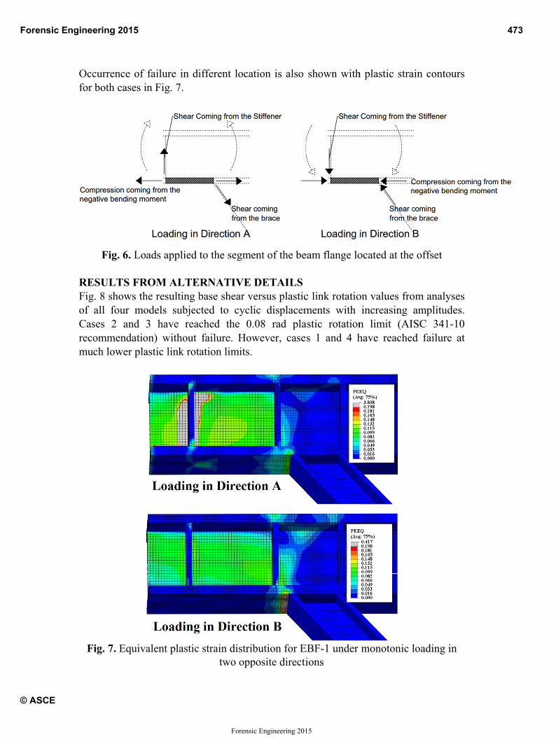
Occfor
REFigof Casrecomu
F
currence of both cases i
Fig. 6. Lo
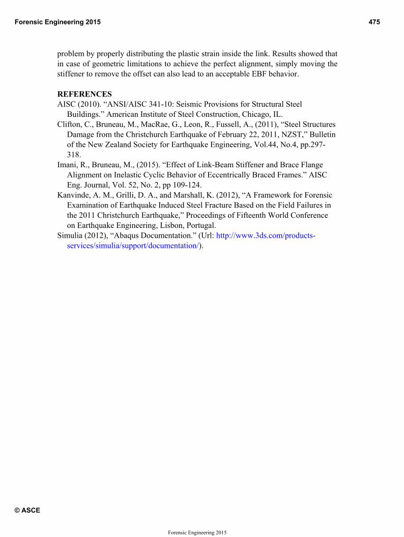
ESULTS FRg. 8 shows thall four moses 2 and 3ommendatioch lower pla
Fig. 7. Equiva
failure in diin Fig. 7.
ads applied t
ROM ALTEhe resulting bodels subjec3 have reac
on) without astic link rota
alent plastic
ifferent loca
to the segme
RNATIVE base shear vcted to cyclched the 0.failure. Howation limits.
strain distribtwo opp
ation is also
ent of the be
DETAILSversus plasticic displacem.08 rad plawever, case
bution for Eposite directi
shown with
eam flange lo
c link rotatioments with astic rotations 1 and 4 h
EBF-1 under ions
h plastic stra
ocated at the
on values froincreasing
n limit (AIhave reache
monotonic l
ain contours
e offset
om analyses amplitudes.
ISC 341-10 d failure at
loading in
Forensic Engineering 2015 473
© ASCE
Forensic Engineering 2015
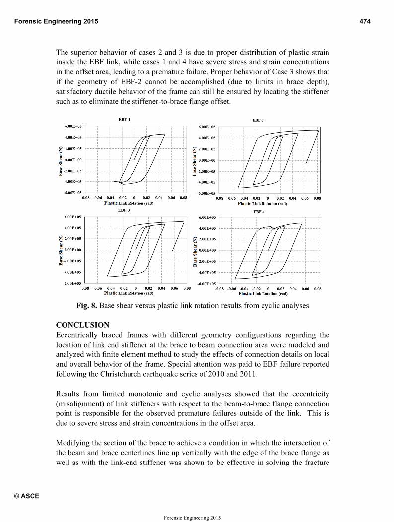
Theinsiin tif tsatisuc
COEcclocaanaandfoll Res(mipoidue Mothe wel
e superior beide the EBFthe offset arethe geometryisfactory ducch as to elimi
Fig. 8. B
ONCLUSIOcentrically bation of link
alyzed with fd overall behlowing the C
sults from lisalignment)nt is respon
e to severe st
odifying the beam and b
ll as with th
ehavior of c link, while ea, leading toy of EBF-2ctile behavioinate the stif
Base shear ve
N braced framk end stiffenfinite elemenhavior of theChristchurch
limited mon) of link stiffnsible for thetress and stra
section of thbrace centerlhe link-end s
cases 2 and cases 1 and
o a prematur cannot be
or of the framffener-to-bra
ersus plastic
mes with difer at the brant method toe frame. Spe
earthquake
notonic and feners with re observed pain concentr
he brace to alines line upstiffener was
3 is due to pd 4 have sevre failure. Praccomplish
me can still bace flange of
link rotation
fferent geomace to beam o study the efecial attentioseries of 20
cyclic analrespect to thpremature farations in the
achieve a con vertically ws shown to b
proper distriere stress anroper behavi
hed (due to be ensured bffset.
n results from
metry configconnection ffects of con
on was paid t10 and 2011
lyses showehe beam-to-bailures outsie offset area.
ndition in wwith the edgebe effective
ibution of pnd strain conior of Case 3limits in br
by locating t
m cyclic ana
gurations regarea were m
nnection detato EBF failu
1.
ed that the brace flange ide of the lin.
which the intee of the bracin solving t
lastic strain ncentrations 3 shows that race depth), the stiffener
alyses
garding the modeled and ails on local ure reported
eccentricity connection
nk. This is
ersection of ce flange as the fracture
f
Forensic Engineering 2015 474
© ASCE
Forensic Engineering 2015
problem by properly distributing the plastic strain inside the link. Results showed that in case of geometric limitations to achieve the perfect alignment, simply moving the stiffener to remove the offset can also lead to an acceptable EBF behavior. REFERENCES AISC (2010). “ANSI/AISC 341-10: Seismic Provisions for Structural Steel
Buildings.” American Institute of Steel Construction, Chicago, IL. Clifton, C., Bruneau, M., MacRae, G., Leon, R., Fussell, A., (2011), “Steel Structures
Damage from the Christchurch Earthquake of February 22, 2011, NZST,” Bulletin of the New Zealand Society for Earthquake Engineering, Vol.44, No.4, pp.297-318.
Imani, R., Bruneau, M., (2015). “Effect of Link-Beam Stiffener and Brace Flange Alignment on Inelastic Cyclic Behavior of Eccentrically Braced Frames.” AISC Eng. Journal, Vol. 52, No. 2, pp 109-124.
Kanvinde, A. M., Grilli, D. A., and Marshall, K. (2012), “A Framework for Forensic Examination of Earthquake Induced Steel Fracture Based on the Field Failures in the 2011 Christchurch Earthquake,” Proceedings of Fifteenth World Conference on Earthquake Engineering, Lisbon, Portugal.
Simulia (2012), “Abaqus Documentation.” (Url: http://www.3ds.com/products-services/simulia/support/documentation/).
Forensic Engineering 2015 475
© ASCE
Forensic Engineering 2015


![V107 4 2016 S IN INSI I NINS 189 ISSN 1991-1696 … · 190 S IN INSI I NINS V107 4 2016 ... frequently in chemical processes and fault detection processes (dynamics). [21] further](https://img.pdfslide.us/doc/110x75/5b7c00157f8b9a9d078b65b1/v107-4-2016-s-in-insi-i-nins-189-issn-1991-1696-190-s-in-insi-i-nins-v107-4.jpg)