Embed Size (px)
Citation preview
METRA. The World’s best kits.™ metraonline.com © COPYRIGHT 2016 METRA ELECTRONICS CORPORATION
REV.
1/6
/201
6 I
NST9
9-58
31 CAUTION: Metra recommends disconnecting the negative battery terminal before beginning any installation, unless the vehicle manufacturer recommends against so. Please check with your local Dealership for more information. All accessories, switches, climate controls panels, and especially air bag indicator lights must be connected before reconnecting the battery or cycling the ignition. Also, do not remove the factory radio with the key in the on position, or the vehicle running. It would be best to remove the key from the ignition and then wait a few seconds before removing the factory radio.
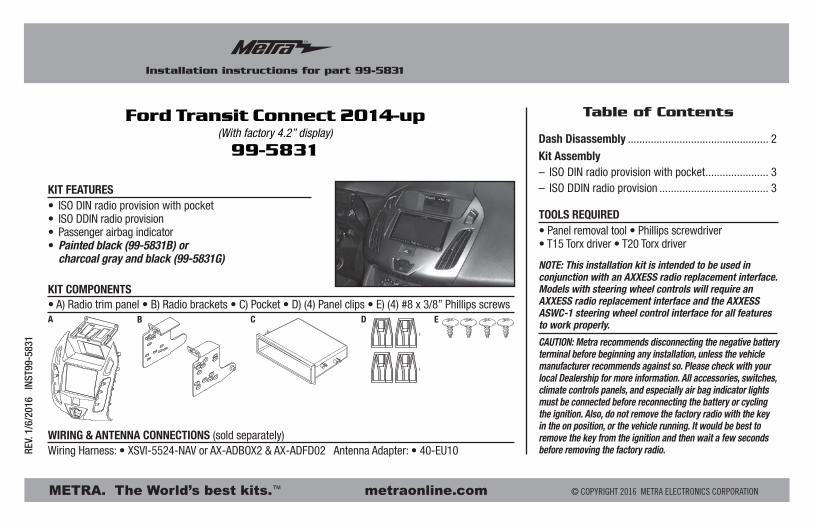
Installation instructions for part 99-5831
• ISO DIN radio provision with pocket• ISO DDIN radio provision• Passenger airbag indicator• Painted black (99-5831B) or charcoal gray and black (99-5831G)
• A) Radio trim panel • B) Radio brackets • C) Pocket • D) (4) Panel clips • E) (4) #8 x 3/8” Phillips screws
KIT FEATURES
KIT COMPONENTS
WIRING & ANTENNA CONNECTIONS (sold separately)Wiring Harness: • XSVI-5524-NAV or AX-ADBOX2 & AX-ADFD02 Antenna Adapter: • 40-EU10
• Panel removal tool • Phillips screwdriver • T15 Torx driver • T20 Torx driver
TOOLS REQUIRED
Ford Transit Connect 2014-up(With factory 4.2” display)
99-5831
A C D EB
Dash Disassembly ................................................. 2
Kit Assembly– ISO DIN radio provision with pocket ...................... 3– ISO DDIN radio provision ...................................... 3
Table of Contents
NOTE: This installation kit is intended to be used in conjunction with an AXXESS radio replacement interface. Models with steering wheel controls will require an AXXESS radio replacement interface and the AXXESS ASWC-1 steering wheel control interface for all features to work properly.

99-5831
2
Dash Disassembly
1. Remove the top panel above the display. (Figure A)
2. Remove (2) T-15 Torx screws above the display/radio panel. (Figure B)
3. Unplug and remove the display/radio panel. (Figure C)
4. Remove the A/C vents and hazard switch from the panel and set aside for kit assembly.
5. Remove (2) T-20 Torx screws from the top of the radio, and then unplug and remove from the dash cavity. (Figure D)
Continue to kit assembly.
(Figure A) (Figure C)
(Figure B) (Figure D)
99-5831
3
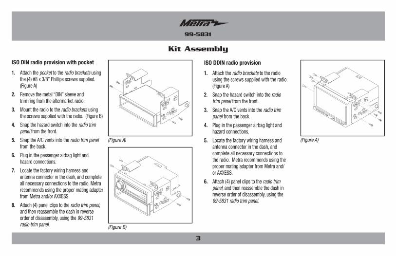
Kit Assembly
(Figure A) (Figure A)
(Figure B)
ISO DIN radio provision with pocket
1. Attach the pocket to the radio brackets using the (4) #8 x 3/8” Phillips screws supplied. (Figure A)
2. Remove the metal “DIN” sleeve and trim ring from the aftermarket radio.
3. Mount the radio to the radio brackets using the screws supplied with the radio. (Figure B)
4. Snap the hazard switch into the radio trim panel from the front.
5. Snap the A/C vents into the radio trim panel from the back.
6. Plug in the passenger airbag light and hazard connections.
7. Locate the factory wiring harness and antenna connector in the dash, and complete all necessary connections to the radio. Metra recommends using the proper mating adapter from Metra and/or AXXESS.
8. Attach (4) panel clips to the radio trim panel, and then reassemble the dash in reverse order of disassembly, using the 99-5831 radio trim panel.
ISO DDIN radio provision
1. Attach the radio brackets to the radio using the screws supplied with the radio. (Figure A)
2. Snap the hazard switch into the radio trim panel from the front.
3. Snap the A/C vents into the radio trim panel from the back.
4. Plug in the passenger airbag light and hazard connections.
5. Locate the factory wiring harness and antenna connector in the dash, and complete all necessary connections to the radio. Metra recommends using the proper mating adapter from Metra and/ or AXXESS.
6. Attach (4) panel clips to the radio trim panel, and then reassemble the dash in reverse order of disassembly, using the 99-5831 radio trim panel.
REV.
1/6
/201
6 I
NST9
9-58
31
KNOWLEDGE IS POWEREnhance your installation and fabrication skills by enrolling in the most recognized and respected mobile electronics school in our industry.Log onto www.installerinstitute.com or call 800-354-6782 for more information and take steps toward a better tomorrow.
Metra recommends MECP certified technicians
Installation instructions for part 99-5831
METRA. The World’s best kits.™ metraonline.com © COPYRIGHT 2016 METRA ELECTRONICS CORPORATION
IMPORTANTIf you are having difficulties with the installation of this product, please call our Tech Support line at 1-800-253-TECH. Before doing so, look over the instructions a second time, and make sure the installation was performed exactly as the instructions are stated. Please have the vehicle apart and ready to perform troubleshooting steps before calling.
INSTRUCCIONES DE INSTALACIÓN PARA LA PIEZA 99-5831
METRA. The World’s best kits.™ metraonline.com1-800-221-0932 © COPYRIGHT 2016 METRA ELECTRONICS CORPORATION
REV.
1/6
/201
6 I
NST9
9-58
31
PRECAUCIÓN: Metra recomienda desconectar la terminal negativa de la batería antes de iniciar cualquier instalación, a menos que el fabricante del vehículo recomiende lo contrario. Verifique con su concesionario local si existe más información. Todos los accesorios, interruptores, paneles de controles de clima y especialmente las luces del indicador de las bolsas de aire deben estar conectados antes de reconectar la batería o ciclar la ignición. Además, no quite el radio de fábrica con la llave en la posición de encendido ni con el vehículo funcionando. Sería mejor retirar la llave de la ignición y esperar unos cuantos segundos antes de quitar el radio de fábrica.
Indice
• Herramienta para quitar paneles • Destornillador Phillips • Destornillador Torx T15 • Destornillador Torx T20
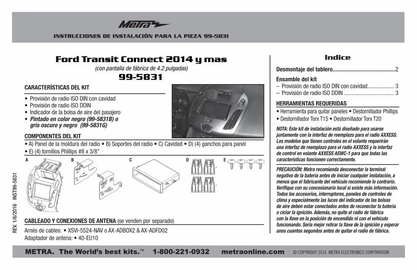
HERRAMIENTAS REQUERIDAS• Provisión de radio ISO DIN con cavidad• Provisión de radio ISO DDIN• Indicador de la bolsa de aire del pasajero • Pintado en color negro (99-5831B) o gris oscuro y negro (99-5831G)
• A) Panel de la moldura del radio • B) Soportes del radio • C) Cavidad • D) (4) ganchos para panel • E) (4) tornillos Phillips #8 x 3/8”
CARACTERÍSTICAS DEL KIT
COMPONENTES DEL KIT
CABLEADO Y CONEXIONES DE ANTENA (se venden por separado)
Arnés de cables: • XSVI-5524-NAV o AX-ADBOX2 & AX-ADFD02Adaptador de antena: • 40-EU10
Desmontaje del tablero................................................2
Ensamble del kit– Provisión de radio ISO DIN con cavidad .................. 3– Provisión de radio ISO DDIN .................................. 3
Ford Transit Connect 2014 y mas(con pantalla de fábrica de 4.2 pulgadas)
99-5831
A C D EB
NOTA: Este kit de instalación está diseñado para usarse juntamente con la interfaz de reemplazo para el radio AXXESS. Los modelos que tienen controles en el volante requerirán una interfaz de reemplazo para el radio AXXESS y la interfaz de control en volante AXXESS ASWC-1 para que todas las características funcionen correctamente.
99-5831
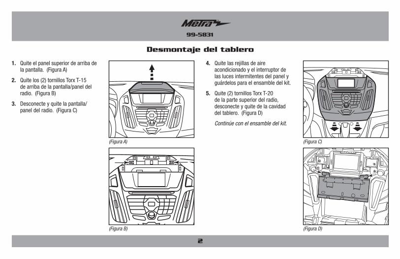
Desmontaje del tablero
2
1. Quite el panel superior de arriba de la pantalla. (Figura A)
2. Quite los (2) tornillos Torx T-15 de arriba de la pantalla/panel del radio. (Figura B)
3. Desconecte y quite la pantalla/panel del radio. (Figura C)
4. Quite las rejillas de aire acondicionado y el interruptor de las luces intermitentes del panel y guárdelos para el ensamble del kit.
5. Quite (2) tornillos Torx T-20 de la parte superior del radio, desconecte y quite de la cavidad del tablero. (Figura D)
Continúe con el ensamble del kit.
(Figura A) (Figura C)
(Figura B) (Figura D)
99-5831
3
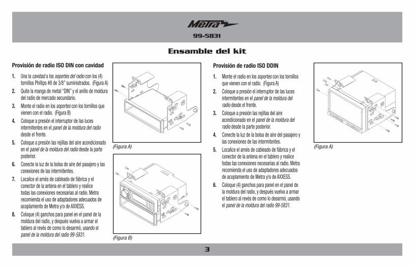
Ensamble del kit
(Figura A) (Figura A)
(Figura B)
Provisión de radio ISO DIN con cavidad
1. Una la cavidad a los soportes del radio con los (4) tornillos Phillips #8 de 3/8” suministrados. (Figura A)
2. Quite la manga de metal “DIN” y el anillo de moldura del radio de mercado secundario.
3. Monte el radio en los soportes con los tornillos que vienen con el radio. (Figura B)
4. Coloque a presión el interruptor de las luces intermitentes en el panel de la moldura del radio desde el frente.
5. Coloque a presión las rejillas del aire acondicionado en el panel de la moldura del radio desde la parte posterior.
6. Conecte la luz de la bolsa de aire del pasajero y las conexiones de las intermitentes.
7. Localice el arnés de cableado de fábrica y el conector de la antena en el tablero y realice todas las conexiones necesarias al radio. Metra recomienda el uso de adaptadores adecuados de acoplamiento de Metra y/o de AXXESS.
8. Coloque (4) ganchos para panel en el panel de la moldura del radio, y después vuelva a armar el tablero al revés de como lo desarmó, usando el panel de la moldura del radio 99-5831.
Provisión de radio ISO DDIN
1. Monte el radio en los soportes con los tornillos que vienen con el radio. (Figura A)
2. Coloque a presión el interruptor de las luces intermitentes en el panel de la moldura del radio desde el frente.
3. Coloque a presión las rejillas del aire acondicionado en el panel de la moldura del radio desde la parte posterior.
4. Conecte la luz de la bolsa de aire del pasajero y las conexiones de las intermitentes.
5. Localice el arnés de cableado de fábrica y el conector de la antena en el tablero y realice todas las conexiones necesarias al radio. Metra recomienda el uso de adaptadores adecuados de acoplamiento de Metra y/o de AXXESS.
6. Coloque (4) ganchos para panel en el panel de la moldura del radio, y después vuelva a armar el tablero al revés de como lo desarmó, usando el panel de la moldura del radio 99-5831.
INSTRUCCIONES DE INSTALACIÓN PARA LA PIEZA 99-5831
METRA. The World’s best kits.™ metraonline.com1-800-221-0932 © COPYRIGHT 2016 METRA ELECTRONICS CORPORATION
REV.
1/6
/201
6 I
NST9
9-58
31
KNOWLEDGE IS POWEREnhance your installation and fabrication skills by enrolling in the most recognized and respected mobile electronics school in our industry.Log onto www.installerinstitute.com or call 800-354-6782 for more information and take steps toward a better tomorrow.
Metra recomienda técnicos con certificación del Programa de Certificación en Electrónica Móvil (Mobile Electronics Certification Program, MECP).
EL CONOCIMIENTO ES PODERMejore sus habilidades de instalación y fabricación inscribiéndose en la escuela de dispositivos electrónicos móviles más reconocida y respetada de nuestra industria. Regístrese en www.installerinstitute.com o llame al 800-354-6782 para obtener más información y avance hacia un futuro mejor.
IMPORTANTESi tiene dificultades con la instalación de este producto, llame a nuestra línea de soporte técnico al 1-800-253-TECH. Antes de hacerlo, revise las instrucciones por segunda vez y asegúrese de que la instalación se haya realizado exactamente como se indica en las instrucciones. Por favor tenga el vehículo desarmado y listo para ejecutar los pasos de resolución de problemas antes de llamar.


![[Cite as , 2016-Ohio-5831.] Court of Appeals of Ohio · 2016-09-15 · [cite as kolosai v.azem, 2016-ohio-5831.] court of appeals of ohio eighth appellate district county of cuyahoga](https://img.pdfslide.us/doc/110x75/5f52c2ef22d86c4f234983c3/cite-as-2016-ohio-5831-court-of-appeals-of-2016-09-15-cite-as-kolosai-vazem.jpg)