Embed Size (px)
Citation preview

0l, AD
ALLEVIATION OF THE SIDE FORCE AND THE YAWING MOMENTACTING ON A SLENDER CONE-CYLINDER BODY AT HIGH ANGLES
OF ATTACKUSING SMALL JET INJECTION AT SUBSONIC ANDTRANSONIC SPEEDS.
SECOND ANNUAL TECHNICAL REPORT
BY
D. ALMOSNINO and J. ROM
SEPTEMBER 1979.
___ EUROPEAN RESEARCH OFFICE L
I ~~UNITED.STATES ARMYU L U L&~LONDON, ENGLAND A
LA. 1 GRANT No. DAERO-78-G-119
C.3E DEPARTMENT OF AERONAUTICAL ENGINEERING
TECHNION - ISRAEL INSTITUTE OF TECHNOLOGYHAIFA, ISRAEL.
Approved for Public Release; Distribution Unlimited,
80 2 4 019

UNCLASSIFIEDSECURITY CLASSIFICATION Of THIS PAGE MW1., Data Ent~rod) R&D 24l6A
REPORT DOCMtENTATION PAGE BEFORE COPEIGFORMI REPORT NUMBER 12 GOVT ACCESSION NO. 3. ftECIPkCNT-S CATALOG NUMBER
.TITLEin Suips TYPE.--- 0
(> Alleviation of the Side Force and the Yawing AnTYPE 0ehia Repo.,*,
Moment Acting on a Slender Cone-Cylinder Body '19 Sep 78- Sep 79.at High Angles of Attack, Usinq Small Jet S'wiwvINIOMoG.19. RER*iT "UNDER
Iniection at Subsonic and Transonic Speeds. ______________
7. £uvh*.o- MT NuM59"fe)
~J.~Rom ) . 'j AERY-78-G-19'IT
9. PERFORMING ORGANIZATION NAME AND ADDRESS 10. PROGRAM ELEMENT. PROJECT. TASK
Israel Institute of Technology,'RASUR UI UUR
Dept. of Aeronautical Engineering)TechnionHaifa, Israel 111 847~
"I~OTROLLING OFFICE NAME AND ADDRESS eftQAE-!-
US Army Research & Standardization Group See 7p9)Box 65, FPO NY 09510 \. 3I. NUMDER or PAGES
14. MONITORING AGENCY NAMES A ADRESS01L different fromw Contrlinga Office) IS. SECURITY CLASS. (of ltis rapact)
/ ~ Unclassified
15aL OECLASSIFICATION'OWwORADiNOSCHEDULE
16. 013TRISUTION STATEMENT (of Vila *mkt)
APPROVED FOR PUBLIC RELEASE
DISTRIBUTION UNLIMITED
77 DISTRIBUTION STATEMENT (of Cho aberace entered in Block 20. if different how faper)
I*. SUPPLEMENTARY NOTES
IS9 KEY WORDS (ContinueO 0 0~0 Ol. d*s ffa,.c..wy and Identify by block rvsbor)
itAinrRACT iCt~as .0mm podsf Nt movw d dfp by week mna1..)
-The effects of small symetrical jets of the side forces of slender bodiesat high angles of attack are investigated. Control as well as alleviationof these forces are,'under-constdera-1eff. The effectvof Reynolds numberand blowing rate are investigated. Side force alleviation -ha-sbe1*1\5obtained for subsonic and transonic flows. -T4~aation of Mach number**4eetfthe magnitude and direction of-t 4eCside forces.,
I,.. DOI ~ Q3 mTIO OF WO 6 I OSOLET $ I ~UNCLASSIFIEDSECUfIITY CL.AmFICATION OF THIS PAGE (Whom bota got~d

AD
ALLEVIATION OF THE SIDE FORCE AND THE YAWING MOMENTACTING ON A SLENDER CONE-CYLINDER BODY AT HIGH ANGLES
OF ATTACKUSING SMALL JET INJECTION AT SUBSONIC ANDTRANSONIC SPEEDS.
SECOND ANNUAL TECHNICAL REPORT
BY
D. ALMOSNINO and J. ROM
SEPTEMBER 1979.
EUROPEAN RESEARCH OFFICE
UNITED STATES ARMY
LONDON, ENGLAND
GRANT No. DAERO-78-G-119
DEPARTMENT OF AERONAUTICAL ENGINEERING ..TECHNIO1 - ISRAEL INSTITUTE OF TECHNOLOGY
HAIFA, ISRAEL.
Approved for Public Release; Distribution Unlimiced.
ABSTRACT
The research presented in this report is a further step in the
investigation of the aerodynamic characteristics of slender bodies
at high angles of attack, in subsonic and transonic Mach numbers,
and it continues the research already done on the effect of small,
symmetrical jet blowing from the nose of a cone-cylinder body on the
alleviation and control of side forces and yawing moments at high
angles of incidence.
In the present investigation the effects of Reynolds number,
Mach number and the effect of varying the blowing rate are investi-
gated. Strong effects on the transition of the boundary layer are
found in the range of Reynolds numbers 0.6 x 10" 0.8 x 10⁶.
Favourable results of side force control and alleviation are obtained
when jet blowing is used together with a transition ring, at low sub-
sonic speed. The experimental results, (including oil flow visualiza-
tion) indicate that the jet injection affects both the transition of
the boundary layer and also the stabilization of the symmetry of the
vortex formation at low speed.
Side force alleviation has been obtained also at high subsonic
and transonic Mach numbers, using a quite low blowing coefficient.
Schlieren photographs indicate that in this case the effect of the
blowing is to stabilize the separation of the vortices from the body,
and seems also to inhibit the vortex breakdown.
The blowing becomes ineffective at the chosen station of injection,
at M 0,85, possibly because of the relative reduction in the blowing
_ _ _a

rate coefficient and because of the shock waves which exist at these
Mach numbers. The variation of Mach number is found to affect the
magnitude of the side force and yawing moment, and more significantly
their directions. However, the observed side forces and yawing moments
are smaller in magnitude at high subsonic and trasonic Mach numbers in
comparison with those obtained in laminar conditions at low speeds.
I.. ... .

- IIl -
TABLE OF CONTENTS
PAGE No.
ABSTRACT I-II
TABLE OF CONTENTS II
LIST OF SYMBOLS IV
LIST OF FIGURES V - VI
1. INTRODUCTION 1- 2
2 LATERAL BEHAVIOUR OF SLENDER BODIES AT HIGHANGLES OF ATTACK, AT SUBSONIC AND TRANSONICSPEEDS 2- 6
3. STUDIES Or SIDE FORCE AND YAWING MOMENT ALLEVIATION ANDCONTROL ON A CONE-CYLINDER BODY AT HIGH ANGLES OFATTACK, USING SMALL SYMMETRICAL JETS INJECTED FROMTHE NOSE, AT SUBSONIC AND TRANSONIC MACH NUMBERS 6 - 14
3.1. The Model and the Experimental Facilities 6 - 7
3.2. Results 7
3.2.1. Low Subsonic Tests 7 - 11
3.2.2. High Subsonic and Transonic Speeds Tests 11 - 12
3.2 3. Reynolds Number Effect 13 - ].4
3,3. Conclusions 14 - 15
REFERENCES 16 - 19
FIGURES 20- 44

- IV-
LIST OF SYMBOLS
Cn yawing moment coefficient, N/qSD
CM pitching moment coefficient, M/qSd
CNOR normal force coefficient, FNOR/qS
Sside force coefficient, Y/qS
C blowing rate coefficient, i u /qS
D reference chord (body diameter)
FN0R normal force to the body
ijet mass flow rate
M Mach number
M, N pitching and yawing moments (about nose tip point).
1 2q dynamic pressure, -V
ReD Reynolds number, tased on body diameter, V, -D2 "
S reference area, (body cross section, -- 1)
uj theoretical jet velocity (assuming fully expanded isentropic
flow)
V freestream velocity
x length measured from nose tip point, along body axis of
revolution
Y side force
a angle of attack
air density
geometrical angles
air viscosity
NOTE: All forces and moments are given in body axes of reference.
g; ,

LIST OF FIGURES
FIGURE No.
1. The cone-cylinder model.
2. Normal force and pitching moment coefficients vs. angleof attack, V - 32 m/sec, no injection.
3. Side force coefficient vs. angle of attack, V - 32 m/sec,no injection.
4. Yawing moment coefficient vs. angle of attack, V - 32 m/sec,no injection.
5. Variation of side force coefficient vs. blowing rate co-efficient, at various angles of attack, V - 32 m/sec,no ransition strip.
6. Variation of yawing moment coefficient vs. blowing rat:ecoefficient, at various angles of attack, V - 32 m/sec,no transition strip.
7. Variation of side force coefficient vs. blowing ratecoefficient, at various angles of attack, V - 32 m/sec,with transition strip at x/d - 0.333.
8. Variation of yawing moment coefficient vs. blowing ratecoefficient, at various angles of attack, V = 32 m/sec,with transition strip at x/d = 0.333.
9. Normal force coefficient and pitching moment coefficientvs. blowing rate coefficient, at various angles of attack,V - 32 m/sec, no transition strip.
10. Normal force coefficient and pitching moment coefficientvs. blowing rate coefficient, at various angles of attack,V - 32 m/sec, with transition strip at x/d - 0.333.
11. Blowing rate coefficient needed for side force alleviationat various angles of attack.
12. Normal force and pitching moment coefficient vs. Mach number,at two angles of attack, no transition strip, no injection.
13. Side force and yawing moment coefficient vs. Mach number, attwo angles of attack, no transitionstrip, no injection.
14. Side force coefficient vs. angle of attack at various Machnumbers, no injection, no transition strip.
.VW

-VI-
LIST OF FIGURES (CONT'D)
FIGURE No.
15. Yawing moment coefficient vs. angle of attack at variousMach numbers, no injection, no transition strip.
16. Side force and yawing moment coefficients vs. blowing ratecoefficient at M - 0.4, at two angles of attack, notransition strip.
17. Side force and yawing moment coefficients vs. blowing ratecoefficient at M = 0.7, at two angles of attack.
18. Side force and yawing moment coefficients vs. blowingrate coefficient at M - 0.85, at 470 angle of attack.
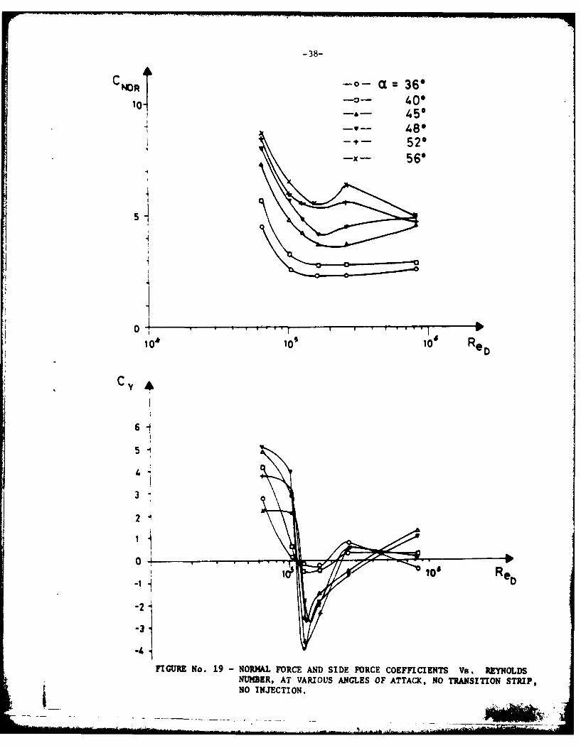
19. Normal force and side force coefficiants vs. Reynoldsnumber, at various angles of attack, no transition strip,no injection.
20. Pitching moment coefficient, vs. Reynolds number at variousangles of attack, no transition strip.
21. Yawing moment coefficient vs. Reynolds number, at variousangles of attack, no transition strip.
22. Oil flow visualization of the cone-cylinder model atV = 32 m/sec, a = 400, with a transition ring atx/D = 0.333.
23. Oil flow visualization of the cone-cylinder model at V = 32m/sec, a = 550, no transition ring.
24. Schlieren photographs of the cone-cylinder model at variousMach numbers, a = 470, no jet blowing.
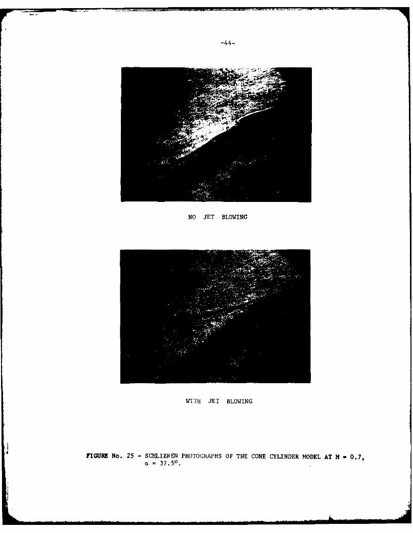
25. Schlieren photographs of the cone cylinder model at M 0.7,a = 37.50 with and without jet blowing.
_ !

1. INTRODUCTION
This report summarizes the research performed under Grant No.
DAERO-78-G-119 during the period December 1st 1978 to August 31st
1979.
The interest in the performance at high angles of attack of
missiles and aircraft is growing. Efforts are made to investigate
the behaviour of slender and not so slender bodies at high angles of
attack and to understand the phenomena related to the development of
asymmetries in the separated vortex flow established about such
bodies.
This asymmetry in the flow causes large side forces and yawing
moments which act upon the body at zero side-slip angles. There-
fore, efficient means of alleviating and controlling side-forces and
yawing moments on such slender bodies at high angles of attack are
investigated. The work presented here is an experimental investigat-
ion of the forces and moments acting on a cone-cylinder body at high
angles of attack, in the subsonic and transonic speed ranges. This
investigation includes the study of the effect of injection of small
symmetrical air jets from the nose of the body and their effects on the
lateral forces and moments.
This program is a continuation of the previous experimental work
presented by Sharir, Portnoy and Rom [9], and also by Rom and Almosnino
[10].
The investigation includes eftects of Reynolds number and transition
44

-2-
strips, rate of jet blowing, and Mach number on the forces and moments
acting on the body at high angles of attack, and it also includes some
flow visualization tests which help to understand the influence of Jet
injection on the flow field close to the body surface.
2. LATERAL BEHAVIOUR OF SLENDER BODIES AT HIGH ANGLES OF.ATTACK, ATSUBSONIC AND TRAISONIC SPEEDS.
Separation of the boundary layer occurs at moderate ,.gle of attack
because of the adverse cross flow pressure gradient on the leeward side
of the slender body.
The separated boundary layer then rolls-up to form a system of
distinct vortices. (The description of separation is more complicated
when the body is not slender).
The rolled up vortex sheet may stay close to the body and be con-
tinuously fed from the separated boundary layer, or it may leave the
body entirely further downstream. Separation line may be expected
to be found near the line of minimum pressure coefficient on the leeward
side of the body, since the separation is caused by the adverse pressure
gradient [1].
Due to geometrical irregularities of the nose of the body and
irregularities in the outer flow, one side of the boundary layer may
separate first from the body, maintaining a certain vortex strength
in the corresponding rolled-up vortex sheet. The other side of the
boundary layer may remain attached and separate only further down-
stream on the body with a corresponding stronger vortex. In this manner
the asymmetric vortex system is generated behind the body at high angles
[ 4 ..

-3-
of attack. This description is supported for example by results
presented in Ref. 2 where it is shown that the side forces are
associated with the asymmetry of circumferential pressure distribution
and the asymmetry of the vortex sheet separation. Visualization presented
in Ref. 1 show that the separation line is shifted towards the windward
side of the body as the angle of incidence is increased. Measurement
of the circumferential angles of separation indicate that asymmetry of
the separation increases as the angle of incidence is increased ( in
laminar boundary layer conditions). The maximum angular difference
nearly coincided with the maximum measured side force. (Maximum angular
difference was of the order of 200 to 400 for sharp slender nose shap'v).
it was found in Refs. 1,2, and 3 that as the angle of attack was high
enough, several vortex separations accured along the body.
The nose shape is a most significant parameter which affects the
side forces. This is supported for example by results of Refs. 6,7, and
8. Refs. 23 and 29 for example show that reorientation of the nose
about the body axis of revolution has a most considerable effect on
the side force and yawing moment sign and magnitude. As it seems
from the state of the art today, it is generally, accepted that the
following phenomenological rules associated with flow asymmetry hold
true:
(1) Initial direction of the side force or yawing moment is un-
predictable because of its connection with small irregularities
in nose geometry. However, once the direction is established,
it does not change for given geometry and flow conditions.

-4-
Change of sign may occur as the angle of incidence is
increased, (even more than once).
(2) Reynolds number has almost no effect on the angle of
incidence for the onset of the asymmetry, but it has a
notable effect on the magnitude of the side force.
(3) Magnitude of the side force increases with the increasing
finess ratio of the nose.
(4) Side forces and yaving moments are very small below a w 250.
Beyond this they increase quite sharply and reach their peaks
between 350 - 500, depending on the Reynolds and Mach numbers
and on the geometry of the configuration.
(5) Installing transition strips may cause reduction of the side
force as much as 80%, causing early transition to turbulent
boundary layer at low Reynolds numbers. (Surface roughness
has also that kind of effect).
Several works try to give a model to predict the position of separa-
tion, the asymmetric vortex structure and the forces and moments acting
on slender bodies at high angles of attack. (For exale, Refs. 3,4,5,
11, 12, 13, 15, 16, 19, 20, 25, 30). As stated in Ref. 14, the success
of these methods is only partial, and the theoretical state of the art
for calculating steady asymmetric vortex patterns around bodies of
revolution at low speeds is semi-empirical. • At present only
engineering methods of limited range of applicability are available.
Side forces and moments may be potentially hazardeous to the
control and stability nf slender configurations such as modern fighters

-5-
and missiles maneuvering at high angles of attack. These side forces
and moments may be overcome by sufficient control authority, or by
aerodynamic devices which suppress the asymetric vortex pattern.
The most common aerodynamic devices used for side force alleviation
are transition strips of all kinds, and vortex generators such as small
strakes usually placed on the forebody or near the nose.
In Ref. 6 reduction of side forces is achieved by adding meri-
dianal strips of grit at angular positions 6 - ± 300. In Ref. 7,
the positioning of a ring on the nose caused a great reduction in the
large yawing moments at high angles of attack. Ref. 8 shows that
addition of vortex generators at the nose caused the separated vortices
to be more symetric at the critical angles of incidence.
Ref. 22 demonstrates the effectiveness of a pair of helical
separation trips to disrupt the lee-side vortices, achieving great
reduction of side forces and yawing moments. The effect of small
strakes on reduction of side forces and yawing moments U demonstrated
in Ref. 23.
It should be noted that the devices described above do suffer from
certain defaults. Some of the transition strips used, reduced side
forces but also had affected the normal force and pitching moment
causing early "stall" effect. Strakes seem to be effective in
alleviating side forces only in a certain limited range of angles of
attack. In general, the role of these devices is a passive one, and
apart from alleviating side forces, these devices could not be used for
active lateral control of side forces and yawing moments at high angles of
attack, for the benefit of improved maneuverability.
-777. 7 7

-6-
The present research continues the investigation on the effect
of air jets blown from the nose of a body of revolution for the
alleviation and also for the control of side forces and yawing
moments at high angles of attack, in subsonic and transonic Mach
numbers (previous results are reported in Refs. 9,10).
3. STUDIES OF SIDE FORCE AND YAWING MOMENT ALLEVIATION AND CONTROLON A CONE-CYLINDER BODY AT HIGH ANGLES OF ATTACK, USING SMALLSYMMETRICAL JETS INJECTED FROM THE NOSE, AT SUBSONIC ANDTRANSONIC MACH NUMBERS. -
3.1. The model and the Experimental Facilities
The experiments are conducted in the Subsonic Wind Tunnel of the
Aeronautical Research Center of the Technion with a cross section of
lm x lm, and in the Transonic Wind Tunnel (blow down, induction type),
with a cross section of 0.8m x O.6m. The model shown in Fig. 1 is
3cm. dia. cylindrical body having an overall finess ratio of 6. The
nose of the body is a pointed cone, with length/diameter ratio of 2.
Using the results of previous experiments [9, 10], it was decided to
concentrate the tests on a sharp cone forebody, and to inject the air
jets from a station which was close to the nose apex at angles of - 300
to the horizontal plane of the body. This location of the pair of
holes for injection gave the best results in the previous tests. The
diameter of the holes was 1.2mm each, perpendicular to the body axis
of revolution. (The diameter of the holes is chosen so as to
obtain blowing velocities of the same order of magnitude as the
tunnel flow speed).
A system of rigid and flexible tubing was arranged in the model
so as to supply the air for symmetrical blowing. A special device
- *1
tA
7
developed and built, which enabled continuous change of the
rate of blowing and its measurement, so that the rate of blowing was
directly recorded by the computer together with all other data read-
ings during the experiments. Internal strain gage balances are used
to measure the aerodynamic forces and moments. The balance chosen
has particularly sensitive elements for the measurements of side
forces and yawing moments. Visualization tests have been performed
using oil-flow at low subsonic speeds and Schlieren photography at
high subsonic and at transonic Mach numbers. Visualization tests have
been carried out with and without injection, for comparison of the
flow patterns. Tests with and without injection were repeated so as
to verify the repeatability of the results.
Special measures were taken in the model installation to assure
that the same angular position of the cone and th. cylinder 1i each
experiment is obtained in the tunnel so as to prevent any changes in
the side force direction and magnitude due to variation in model
installation.
The symmetry of the blowing jets is checked by blowing with no
external flow and detecting zero lateral forces and moments.
3.2. Results
3.2.l.Low Subsonic Tests
The low subsonic tests are carried out at 32 m/sec. in an angle of
attack range of -10° to 90° . Comparison is made between tests without
a transition device, and tests with a transition strip (ring) of 0.1mm.
thickness placed at x/d 0.333 from the nose tip. (The thickness and
L. .........

-8
location of the transition ring are chosen according to Refs. 27, 28. The
effect of the jet blowing is also tested with the without transition ring..
From Fig. 2 it can be seen that the normal force and pitching moment
coefficients are only moderately affected by the transition ring especially
near the region of their peak. Normal force peak with a transition ring
is about 10-15% less than without transition, while there is only a slight
difference between the curves up to 400 angle of attack.
However, Figs. 3 and 4 show that the influence of the transition ring
is quite large on the side force and yawing moment coefficients. There is
a great reduction in the side force and yawing moment, using the transition
ring, up to about 560 angle of attack, while peak position for the side
force being shifted down to about a = 410 (from a = 480 without the
transition ring). The maximum side force coefficient is reduced by 25Z,
using the transition rings. It is also interesting to note the development
of a negative secondary peak of side force , with the transition ring, at
about a = 600. Worth noting is also the fact that without the transition
ring the maximum side force coefficient is at a = 480, while the yawing
moment peak is occuring at about a = 40° . The position of both these
peaks occurs at about a - 410 when the transition ring is present. The
angle of onset of side forces is unaffected by the transition ring and
stays at about 240.
Effects of Jet Injection on Side Forces and Yawing Moments, with andwithout Transition Ring.
The effect of jet injection is demonstrated in Figs. 5 and 6 (no
------ ---
-9
transition ring) and in Figs. 7 and 8 (with transition ring). In Figs.
5 and 6 it can be seen that jet blowing from the chosen station on the
0nose effectively alleviated side forces and yawing moments above a - 44
Blowing is ineffective below a = 440, without a transition ring.
The behaviour of the curve describing the variation of C y or Cn
versus the blowing coefficient Cp has a special form (when the blowing
is effective). It can be seen that there is a sharp reduction in C and
Cn at a very low blowing rate, and as C 1 grows there is a change of
sign, reaching a negative but lower peak (in absolute value). That peak
is usually much more "flat" and when C is increased further, a second
zero of C and Cn may be achieved, sometimes accompanied later by a
second positive peak at high blowing rates. The very sharp change in
C and Cn at very low blowing rates might be caused by the jets, which
* act to trip the boundary layer. This possibility is supported by some oil
flow visualization photographs, in which there is a distinct curved pattern
starting from the injection holes, rolling up along the conical nose, up to
the shoulder, or to the nearest separation lines. However, Figs.22,23 which
are examples of the oil flow visualization photographs show that the small
jets also affect the symmetry of the separation lines along the leeward side
of the body. The effect of the jets on the boundary layer transition is
clear also from their influence on CNOR especially at high angles of
incidence (Figs. 9, 10).
When a transition ring is present,(Figs. 7 and 8), the sharp
change in C and C disappears i.t a = 320 and 360, and startsn
appearing again at a - 40 up to about 580. This can be explained by
the fact that the small transition ring is more effective at the lower

- 10o -I..
range of angles of attack in reducing sides forces, but it is less
efficient at the higher angle of attack range, where the cross flow
plane becomes more dominant, and there the effect of the jets is
stronger.
Fig. 10 supports this view, where the normal force is unaffected
by the Jets at a - 320, 360 with a transition ring, and starts being
affected at higher angles of incidence.
The influence of injection apart from transitional effect is
clearly demonstrated in Fig. 2Z , where the transition ring is
present, and the angle of incidence is 40° . Here the injection completely
alters the separation pattern, apart from making it more symmetrical.
The pair of separation lines on the leeside of the cone which continues
over the shoulder along the cylinder without injection, breaks at the
shoulder when injection is present,and a new pair of separation lines
appears on the cylinder. The shoulder between the cone and the
cylinder has been observed to have its own effects on the flow pattern,
some of which are weaker or non-existent in models such as ogive-
cylinder bodies. It should be noted that in the last case a higher
blow rate was used for side force alleviation than in "transitional"
cases (See Fig. 7 for a - 400).
The amount of flow rate coefficient needed for side force alleviation
vs. the angle of incidence is sketched in Fig. 11.
It is clear that high blowing rate is needed at the lower range
of a , up to about 460 480. Then there is the range of a(48° to 580
with transition ring, or 480 to 640 without it) where very low blowing

- 11 -
coefficient is needed to eliminate even high side forces. The last
range corresponds to the negative slope region of Cy vs. a, in
general (Fig. 3).
The sharp rise in the required blowing coefficient at a - 60°,
(with transition ring) corresponds with the negative peak of side force
(Fig. 3), and the amount needed for side force alleviation is almost the
same as was needed to alleviate the side force of the same positive
amount at a - 400. (The border lines which appear in Fig. 11 for
some values of a are indicaLing the region of blowing rates in which
side force is effectively zero or strongly alleviated).
3.2.2, High Subsonic and Transonic Speeds Tests
The effect of Mach number at two fixed angles of incidence, a = 460,
a= 48°, is shown in Figs. 12, 13. The rise in CNOR and the equivalent
change in CM because of Mach number effect starts at about M = 0.63.
It is interesting to see that both side force and yawing moment change
their sign around M = 0.7, because of Mach number effects. (The
reason might be connected with the first appearance of shock waves
at that Mach number). The C, and Cn curves then reach an
unstable peak between M = 0.77 and M = 0.92. This result is different
from the conclusions presented in Ref. 14 which states that side forces
on body of revolution are reduced to zero for crossflow Mach number
greater than about 0.5.
It can be seen (Fig. 13) that there is a great reduction in the side
force and yawing moment when the Mach number exceeds M = 0.92. (Equiva-
lent cross flow Mach number is about 0.66).
. . . . . . . . . . . . . . . . , ..1. .'

- 12 -
Fig. 2- shows the development of the flow as the Mach number
grows from 0,4 to 1.1, using Schlieren photographs.
The variation of C and C vs. the angle of incidence atn
various Mach numbersis shown in Figs. 14, 15. Noteworthy is the sharp
change in CY and C at M = 0.4, from a mild positive peak to an
sharp negative peak, and then again to a mild positive peak. The
reason might be connected with vortex breakdown. In general, the
side forces and yawing moments above M = 0.4 are about 4 or 5 times
less than at M = 0.1, and the reason is that the flow becomes fully
turbulent, together with possible vortex breakdown phenomenon. (See
also discussion of Reynolds number effect).
The Effect of Jet Blowing at High Subsonic and Transonic Mach Numbers.
The effect of jet blowing on C and Cn is presented in Figs. 16
to 18.
The rates of jet blowing coefficient became quite small as the
Mach number increased, so its effect is only partial.
At K - 0.4 (Fig. 16) jet blowing is ineffective at a = 460 and
causes an unstable change in C% and Cn at a = 48.50. This is
explained by results shown in Figs. 14, 15, where a sharp slope in Cy
and C is observed in this region.n
At M = 0.7 (Fig. 17) there is a considerable alleviation of Cy
and Cn at a - 37.50, but the blowing caused higher C y and Cn
at a - 46 , where the side force is initially close to zero.
Schlieren photographs taken at a - 37.50 and at that Mach number

with and without injection reveal some information about the effect of
jet blowing in this case. It can be clearly seen in Fig. 25 that the
main nose separated vortex line is broken near the shoulder of the
cone without injection, (possibly because of the small shock line
starting at this point). Secondary separations are observed further
on the cylindrical part. However, with the blowing it can be seen
that a distinct vortex is separated from the nose, trailing high
above the cylindrical part and not broken in the shoulder region.
Secondary separations are still observed on the cylinder.
At M - 0.85 (Fig. 18), jet blowing at a - 470 managed to
alleviate C,, but only reduced C n . No effect of jet blowing at
this rate is noted at N-
One also should remember that at transonic Mach numbers, where
shock waves are involved, there might be a stronger importance to
the position of the jet blowing stations.
The effect of the small rate of jet blowing at transonic and
high subsonic Mach numbers is noteworthy (when extitent). Clearly
the effect is not due to transition of the boundary layer because
of the already high Reynolds numbers, and tunnel noise level. The
Scblieren photograph of Fig. 25 clearly reveals that it has to do
with vortex separation and breakdown. (The fact that jets can
finhibit vortex breakdown is already known).3.2.3. Reynolds Number Effect
Fig. 19 shows the effect of Reynolds number on CNOR and C.,
at various angles of attack. It is clear that there is a strong

- 14 -
transition effect of ReD on these forces, at all angles of attack,
causing a sharp drop in CNOR at the higher Reynolds numbers which
explains the lower CNOR for a given a at M = 0.4, compared to the
M - 0.1 results. At higher angles of incidence the variation of the
CNOR is somewhat similar to the variation of the drag coefficient
(and indeed at those angles a large portion of the CNOR is due to
the drag). The behaviour of C is very interesting.
It is clear that there is a sharp change of sign in C Y in the
transitional region, and then a more moderate rise, changing sign
again at a higher ReD' These results show clearly that the direction
of sideforce might be changed because of Reynolds number effects in the
transition region. Therefore under such conditions the side force may
not stay in its original direction as some investigators suggested.
(in this connection see also Refs. 17, 21 and 25).
Figs. 20 and 21 show the effect of Reynolds number on the pitching
moment and on the yawing moment coefficients. The variation in the
pitching and yawing moments at various Reynolds numbers indicate that
unstable behaviour of the model may occur at high angles of attack,
requiring special attention in the control considerations of these
designs at certain ranges of speeds and altitudes. In view of these
phenomena, blowing of jets may be a useful method for stabilization and
controlling at such flight conditions.
3.3. Conclusions
The experimental investigation performed on the cone-cylinder
body revealed important features of such configurations at high
-15 -
angles of attack, and their dependence on Mach number and Reynolds
number.
At least some of the so called uncertainties in the prediction
of the general behaviour of side forces and yawing moments are found
to be clearly dependent on these parameters. The strong effect of
jet blowing on latteral forces and moments at various Mach numbers
and Reynolds numbers has been demonstrated. At low subsonic speed,
jet blowing at the chosen station may be used efficiently for side
force alleviation and even control, especially when a transition ring
is present also. Jet blowing at small rates is sufficient to
alleviate side forces in some cases at high subsonic and transonic
Mach numbers, but the rate required for controlling these forces must
be much larger. Further experiments are needed at the transonic range
in order to investigate the effects of parameters such as higher blowing
rates and the effects of changes in the blowing stations. More visua-
lization tests can also be useful in order to understand better the
various roles of jet injection, in alleviating side forces and yawing
moments.

-16-
REFERENCES
1. Pick, G.S., Investigation of side forces on ogive cylinder bodies
at high angles of attack in the M - 0.5 to 1.1 range , AIAA Paper
No. 71-570, June 1971.
2. Krouse, J.R., Induced side forces on slender bodies at angles of
attack and Mach numbers of 0.55 - 0.80, NSRDC Test Rept. May 1971.
3. Thomson, K.D., and Morrison, D.F., The spacing position and strength
of vortices in the wake of slender cylindrical bodies at large
incidence, Weapons Research Establishment, Salisbury, South Australia,
Tech. Rapt. NSA 25, June 1969, (also Jr. of Fluid Mech., Vol. 50,
Pt. 4, Dec. 1971, pp. 751-78 3).
4. Lamont, P.J., and Runt, B.L., Pressure and force distribution on a
sharp-nosed circular cylinder at large angles of inclination to a
uniform subsonic stream, Jr. of Fluid Mechanics, Vol. 76, Pt. 3,
pp. 519-559, Aug. 1976.
5. Lamont P.J., and Hunt, B.L., Prediction of aerodynamic out of plane
forces on ogive-nosed circular cylinders, Jr. of Spacecraft and
Rockets, Vol. 14, No. 1, Jan. 1977, pp. 31-44.
6. Keener, E.R., and Chapman, G.T., Onset of aerodynamic side forces
at zero sideslip on symmetric forebodies at high angles of attack,
AIAA Paper 74-770, Aug. 1974.
7. Letko, W., A low speed experimental study of directional characteristics
of sharp-nosed fuselage through a large angle of attack range at zero
angle of sideslip, NACA TN 2911, March 1951.
8. Clark, W.R., Peoples, J.R., and Briggs, M.M., Occurence and inhibition
of large yawing moments during high incidence flight of slender missile
configurations, AIAA Paper No. 72-968, Sept. 1972.

9. Sharir, D., Portnoy, H., and Rom, J., "A Study of the effects of
jets injected from a slender body of revolution on the side forces
acting on it at large angles of attack in low speeds, TAE Rept.
337, May 1978, Technion, Israel Inst. of Technology.
10. Rom, J., and Almosnino, D., Studies of Non-linear aerodynamic
characteristics of finned slender bodies at high angles of attack,
TAE Rept. No. 349, Nov., 1978, Technion,Israel Inst. of Technology.
11. Fidler, J.E.,Approximate method for estimating wake vortex strength,
AIAA Jr. Vol. 12, No. 5, May 1974.
12. Marshall, F.J., and Deffenbaugh, F.D., Separated flow over bodies of
revolution using an unsteady discrete vorticiry cross wake, NASA CR
2414, June 1974.
13. Mendenhall, M.R., and Nielsen, J.N., Effect of symmetrical vortex
shedding on the longitudinal aerodynamic characteristics of wing-
body-tail combinations, NASA CR 2473, Jan. 1975.
14. Nielsen, J.N., Nonlinearities in missile aerodynamics, AIAA Paper
No. 78-20, Jan. 1978.
15. Angelucci, S.B., A multi vortex method for axisymmetric bodies at
angles of attack, Jr. of Aircraft, Vol. 8, No. 12, 1971, pp 959-966.
16. Angelucci, S.B., Multi vortex model for bodies of arbitrary cross
sectional shapes, AIAA Paper No. 73-104, 1973.
17. Clark, W.H., and Nelson, R.C., Body vortex formation on missiles at
high angles of attack, AIAA Paper No. 76-65, Jan. 1976.
18. Clark, W.U., Body vortex formation on missiles in incomressibe
flows, AIAA Paper No. 77-1154, Aug. 1977.

- 18 -
19. Deffenbaugh, F.D., and Koerner, W.G., Asymetric wake development and
associated side force on missiles at high angles of attack, AIAA Paper
No. 76-364, July 1976.
20. Smith, J.H.B., Inviscid fluid models, based on rolled-up vortex sheets,
for three dimensional separation at high Reynolds number, RAE TECH.
MEMO. AERO 1738, Nov. 1977.
21. Przirembel, C.E.G., and Shereda, D.E., Aerodynamics of slender bodies
at high angles of attack", Jr. of Spacecraft and Rockets, Vol. 16,
No. 1, Jan-Feb, 1979.
22. Rao, D.M , Side-Force alleviation on slender, pointed forebodies at
high angles of attack, AIAA Paper No. 78-1339, 1978.
23. Coe, P.L., Chambers, J.R., and Letko, W., Asymmetric lateral-directional
characteristics of pointed bodies of revolution at high angles of
attack, NASA TN D-7095, Nov. 1972.
24. Clarkson, M.H., Malcolm, G.N., and Chapman, G.T., "A Subsonic, high-
angle-of-attack flow investigation at several Reynolds numbers, AIAM
Jr., Vol. 16, No. 1, Jan. 1978.
25. Redding, P.J., and Ericsson, L.E., Maximum vortex-induce side force,
Jr. of Spacecraft and Rockets, Vol. 15, No. 4, July-Aug. 1978.
26. Schwind, R.G., and Mullen, J. Jr., "Laser Velocimeter measurements
of slender body wake vortices, AIAA Paper No. 79-u302, Jan. 1979.
27. Braslow, A.L., and Knox E.C., Simplified method for determination
of critical height of distributed roughness particles for boundary-
layer transition at Mach numbers from 0 to 5, NACA TN 4363,1958.
"!

- ig -
28. Stewart, D.G., and Fisher, S.A., "Some observations of boundary
layer transition on cones at subsonic and supersonic speeds, ARL
Note ME 267, 1965.
29. Keener, E.P., Chapman, G.T., Cohen, L., and Taleghani, J., Side
forces on a tangent ogive forebody with a finess ratio of 3.5
at high angles of attack and Mach numbers from 0.1 to 0.7,
NASA TMX-3437, Feb. 1977.
30. Wardlaw, A.B., Jr., Multivortex model of asyuetric shedding on
slender bodies at high angle of attack, AIAAPaper Yo. 75-123, Jan.
1975.
b
-20-
4 I4-J Ia
'-4
Ii 0ii ~i
Ii b UI i S
'-4
1~ IIAi U
I

-21-
Cnor10.
8.
6. 6.- - No transition strip
4. Transition stripat X OM.333d
2.
0.16 32 48 61 s0 96
-32.
-. 0.
-48.
Cm
FIGURE No. 2 - NOT L FORCE AND PITCHING MOMENT COEFICIENTS Vs. ANGLEOF ATTACK, V - 32 a/sec, NO INJECTION.
34 . . ... . ." '

-22-
aDaODN
oU
I-d
-C
WS
-7a* Iad
c 9.
00
toa
co1
4 t S - to

-23-
0n u
0 II
0 EI
(.4zI.-4
.00
z
04-
00fa
II 0a
-24-
A 3
2
0
010 20 30 4
cy - ~ - a= 48
-A- Q:44*
3
010 20 30 40
13
2
3~lO
1, 4 o a 6 '
3~ 52i

Co a20 30 60
-0 a x36* C4& 103
.. 1
c0
12 a 4
CL A'
102 04
a=52
VARIATION OF YAWING MOMENT COEFFICIENT Vs. BLOWING RATEFIGURE No. 6 -COEFFICIENT, AT VARIOUS ANGLES OF ATTACK, V 32 r/sec,
No TRANSITION STRIP.
cv-.- a 32-50
0
C-. a 40O
~~a= 44e
-oa z= 48.50
0 0
-2I
-C- 560
a. 50. 5@0 0
1O 20 s0oScp 103
KIGU2 No. 7 - VAITO OFSD OC OFIIN Vs. BLOWING RAT
COEFFICIENT, AT VARIOUS ANGLES OF ATTACK, V - 32 m/sec, WITH

CM -27-
t 6
2
10 200
30 s0o5 60 70 so
-60
- 12
3 -- a 32.0
2
0 1
-33
-3
VARIATION OF YAWING MOM1ENT COEFFICIENT Vs. BLOWING RATEFIGURE No. 8 -COEFFICIENT, AT VARIOUS ANGLES OF ATTACK, V *32 rn/eec,
WITH TRANSITION STRIP AT x/d 0.Q333.

7.7
C -a--2 7a-N
12
0Iw
6
2
0
CN10 30 so 70 CW 10 3
4
FE CURE No. R - CONTINUED

CNOR -8
10
8
2
1020 30 40 Cp a0 3
o = 36.1a oiao = 4.3"
-10 'va 461X L 5210+ Cl 6.4-2
-20
-30
-35
FIGURE No. 9 -NORMAL FORCE COEFFICIENT AND PITCHING MOMNENT COEFFICIENTVs. BLOWING RATE COEFFICIENT, AT VARIOUS ANGLES OF ATTACK,L V 32 r/sec, NO TRANSITION STRIP.

~ 56-3
--t= 5 .1*
x' gO C0 z -5
2.m32
30 '0
V2
F0
10.-
1b
d
C m FIGURE No. 10 NOWRMAL FORCE COEFFICIENT AND PITCHING MOMENT COEFFICIENTVs. BLOWING RATE COEFFICIENT, AT VARIOUS ANGLES OF ATTACK,V -32 m/sec, WITH TRANSITION STRIP AT x/d *0.333.

-30-
60H
-0- WTH TRANSITION AT x/d 0.333
--X NO TRANSITION
5O
40
YMAX. (FIRST PEAK)
(POSITIVE)
30
CYMU.(SECOND PEAK)(NEGATIVE)
(6
20
cYKA (POSITIVE)
NO TRANSITION
10
030 34 36 42 46 50 54 so 62 [el
FIGURE No. 11 - BLOWING RATE COEFFICIENT NEEDED FOR SIDE FORCE ALLEVIATIONAT VARIOUS ANGLES OF ATTACK.

-31-
Cnor a4
S -A- a=48*
6
0 0A 0. 5 0.6 0.7 0.s 0.9 1.0 I1.1
-16
.18
-20
-22
-24
Cm
FIGURE No. 12 -NORMAL FORCE AND PITCHING I43NET CO)EFFICIENTS Ve MACHNMBKER, AT TWO ANGLES OF ATTACK, NO TRANSITION STRIP, NOINJECTION.

K -32-
-A- a= 4 8*
Il= 8
0.50
c n10
4
z
-2
-4
FIGURE No. 13 -SIDE FORCE AND YAWING MOMENT COEFFICIENT Va. MACH NUMBOER,AT TWO ANGLES 0! ATTACK, SO TRANSITION STRIP, NO INJECTION.

c-JJ
to
40
x- U
4 0 P.
-34-
U0
04
IL.

-35-
01
FIGURE~~~~~~~~~~~~~~ No16SDOCEADYWN.OMN OFIINT a LWNRAECEFCETATM 04 TToANLSO TAK
NOTASTINSRP

-36-
C"
0 10
0.8 -- 37 S
0.63
04
4641
4
FIGU No. 17 -sIDs yo=C AND yAMING Nb3NT =MFFCI="T Vs. * 57241 RA72OOU7CIUWT AT 14- 0.7, AT 711 AGLES 07p ATrACE.

c y1.2
1-.1
0.9.
0.8-
0.6 0.5 1 1.5 Cp 10
CN
0.5 1 .5 cg'10,
.4
FIGURE No. 18 -SIDE FORCE AND) YAWING MOMENT COEFFICIENTS Vs. BLOWINGRATE COEFFICIENT AT M -0.85, AT 47 0 ANGLE OF ATTACK.
-38-
c NR -o a 36*1ol 400
450
48052*560
10* 10 10' R
61
5-
3-
FIGURE No. 19 -NORMAL FORCE AND SIDE FORCE COEFFICIENTS Vs. REYNOLDSNUMBER, AT VARIOUS ANGLES OF ATTACK, NO TRANSITION STRIP,j NO INJECTION.

-19-
0~ 0. e
0z
z
0
zu
p 1-4
... ...... ....
C A , il am I

-40-
KC16
12
10 R
-121
[ -16
-20-
FIGURE No. 21 -YAWING MOMENT COEFFICIENT Vs. REYNOLDS NUMBER, ATVARIOUS ANGLES OF ATTACK~, NO TRANSITION STRIP.

-41-
NO JET BLOWING
WITH JET BLOWING
FIGURE No. 22 - OIL FLOW VISUALIZATION OF THE CONE-CYLINDER MODEL ATV - 32 m/sec, a - 400, WITH A TRANSITION RING AT x/D 0.333.

-42-
NO JET BLOWING
WITH JET BLOWING
FIGURE No. 23 - OIL FLOW VISUALIZATION OF THE CONE-CYLINDER MODEL AT V=32
m/seec, a 550, NO TRANSITION RING.

-43-
M -0.46 M -0. 71
M- 0.87 M -1.06
FIGURE No. 24 -SCHLIUEK PROTOGRAPHS OF TME CONE-CYLINDER MODEL AT VARIOUSHACK NUMBERS, c - 470, NO JET BLOWING.
-44-
No JET BLOWING
WITH JET BLOWING
FIGURE No. 25 -SCHLIEREN PHOTOGRAPHS OF THE CONE CYLINDER MODEL AT M 0.7,