Embed Size (px)
Citation preview

Our
Product for your Project
A l l a t o n e s i g h t
s e l f - l I m I T I n g H e aT I n g Ta P e s
f l U o Ro P o ly m e R- I n s U l aT e D H e aT I n g C a b l e · m I n e R a l- I n s U l aT e D H e aT I n g C a b l e
C o n T Ro l T e C H n I q U e

Our reputation as specialist for electrical heating systems is due to the functionality and high economic benefit of our products. We take pride in translating this into action for you and your project. Our experience is your advantage.
Everything must fit to each other: We offer all services under one roof, from developing and planning to manufacturing and commissi-oning. Located in Dortmund with a staff of more than 90 employees, we realise projects all around the world – and are therefore close to you, our customer.
We know about the requirements of our customers. Take our word for it!
We focus on the projects you wish to realize.Electric Heating Systems made by Klöpper-Therm.
The specialists for electric heating systems
2

Ta b l e o f C o n T e n T s
P Ro D U C T o V e RV I e W 3
The specialists for electric heating systems
Self-limiting Heating Tapes Explosion-proofDatasheet self-limiting heating tape Type KT-J Page 4
Datasheet self-limiting heating tape Type HKT-J Page 9
Product list connection components Page 14
Self-limiting Heating Tapes for Industrial Applications
Datasheet self-limiting heating tape Type KT-JT Page 22
Product list connection components Page 27
2
Fluoropolymer-insulated Heating Cables
Datasheet single wire heating cable Type TCTEX-H.*/TCTEX-L-* Page 30
Datasheet Ex-connection sleeve Type PTFE Ex 7025 Page 35
Datasheet Ex-connection sleeve Type PTFE Ex 7160 Page 36
Product list connection components Page 38
3Mineral-insulated Heating Cables
Datasheet mineral-insulated heating cable Page 44
Product list connection components Page 50
45Inquiry form for projection of heat tracing systems Page 70
1
Control TechniqueUniplex III Page 55
Uniplex III Page 60
Unigate RS 485 Profibus Page 62
Pt-100 Page 63
Control boxes Page 68

The specialists for electric heating systems
4
self-limiting Heating Tape Type KT-J
for Frost Protection and Process Temperatures up to max. 65 °C
Type Power Art.-No.KT23J 9 W/m at +10 °C 101228
KT25J 15 W/m at +10 °C 101229
KT28J 25 W/m at +10 °C 101230
KT210J 32 W/m at +10 °C 101231
All heating tapes are tailored according to the specifi c requirements of our customers.

T y P e K T- J
R U b R I K 2
The specialists for electric heating systems
s e l f - l I m I T I n g H e aT I n g Ta P e s 5
Description The Klöpper-Therm heating tape type KT-J is a parallel heating cable with self-limiting characteristic. An irradiation cross-linked semiconductive polymer core material is extruded over the multi-stranded, tin-pla-ted copper bus wires (1.22mm²). The semiconductive core material increases or decreases its heat output in response to temperature changes. Two jackets provide extra dielectric strength, moisture resistance and pro-tection from impact and abrasion damage. The inner thermoplastic jacket is extruded over and bonded to the core material. A thermoplastic elastomer outer jacket is then extruded over the inner jacket. A tinned copper braid is installed over the second jacket, provi-ding a continuous ground path. The braid is covered by a fl uoropolymer overjacket, featuring an excellent chemical resistance. Thus, the heating tape provides an optimum protection against corrosive or chemical impacts.
Principle of Operation The parallel bus wires apply voltage along the entire length of the heating tape. The semiconductive core provides an infi nite number of parallel conductive paths, permitting the heating tape to be cut to any length in the fi eld with no dead or cold zones developing. The heating tape derives its self-limiting characteristic from the inherent pro-perties of the semiconductive core material. As the core material temperature increases, the number of conductive paths in the core material decreases, automatically decreasing the heat output. As the temperature of the core ma-terial decreases, the number of conductive paths increases, causing the heat output to increase. This occurs at every point along the length of the heating tape, thus adjusting the power output to the varying conditions along the pipe. The self-limiting effect allows the heating tape to be overlapped without creating hot spots or burnout. Since the heating tape regulates its heat output itself, it provides an effi cient use of power, producing heat only when and
where it is needed and limiting the maximum sheath temperature at the same time.
Application The Klöpper-Therm heating tape type KT-J is highly suitable in maintaining the fl uid fl ow of a medium under low ambient tem-
peratures. Frost protection systems and systems with low power density such as product pipelines, fi re protection, process water,
dust suppression systems, hot water and anti-icing (domestic technique) are typical applications for this product.
1 23
45
6
1 fl uoropolymer overjacket
2 metal braid
3 outer thermoplastic elastomer jacket
4 self-limited conductive core
5 bonded inner thermoplastic jacket
6 stranded-plated copper conductors
1

The specialists for electric heating systems
6
Rating Data of Heating Tapes
*The temperature classification of electrical equipment is applied in hazardous areas and defines the surface temperature the electrical devices do not exceed during proper operation. Regarding the marking of electrical equipment you have to distinguish between gas explosion and dust explosion hazard areas.
The heating tapes have been certified for use in hazardous areas, endangered by gases and dusts, of zones 1 and 2 or 21 and 22 according to EC Type Examination Certificate No. KEMA 04 ATEX 2146U. Klöpper-Therm delivers a complete range of connection boxes, connection and end seal kits, certified together with the heating tapes under EC-Type Examination Certificate No. KEMA 05 ATEX 2102X.
Dimensions (nominal): width 11.9 mm, thickness 6.0 mmWeight: 130 g/mMinimum assembly temperature: -40 °CMinimum bending radius: 12 mm at -40 °C
Type Designation
Watt/Meterat 10 °C
Service Voltage
(V AC)
Maximum Length of
Heating Tape (per Branch)
(m)
Maximum Exposure
Temperature Permanent
(°C)
Maximum Exposure
Temperature Temporary
(°C)
Temperature Class
(Gas Ex-Area)
Max. Surface Temperature
(Dust Ex-Area)
KT23J 9 230 185 65 85 T6 T85 °C
KT25J 15 230 155 65 85 T6 T85 °C
KT28J 25 230 125 65 85 T5 T100 °C
KT210J 32 230 115 65 85 T5 T100 °C

T y P e K T- J
R U b R I K 2
The specialists for electric heating systems
s e l f - l I m I T I n g H e aT I n g Ta P e 7
Circuit Breaker Selection (C-Characteristic)
Remarks:1. The circuit breaker size must be based on minimum start-up temperature, since the inrush current of the heating tapes increases with decreasing ambient temperature.
2. Do not exceed maximum recommended heating tape length per branch, indicated for each type of heating tape. The longer heating tape lengths marked with two stars (**) are only possible by parallel connection of two or several branches (each of these branches must not exceed the recommended heating tape length per branch!) on the breaker. Do not exceed max. recommended length of heating tape indicated in the table.
3. When connecting two or more different wattage heating tapes in parallel on the same breaker, please use the 16 amps column (16A) and divide 16 amps by the maximum heating tape length indicated with reference to the desired minimum start-up temperature. Thus you get an amps/meter value for each type of heating tape. Multiply the length of each heating tape with the derived amps/meter value. The single amp values calculated have to be added up. The added value must not exceed the amperage rating of the breaker.
4. For electrical heating systems, Klöpper-Therm stipulates the use of a residual current device with a residual cur-rent rating not exceeding 300 mA. Residual current devices with a residual current rating of 30 mA should be used preferably.
TypeDesignation
Start-up Temperatur
(°C)
Max. Recommended Heating Tape Length (in Meters) vs. Circuit / Breaker Size
16 A 20 A 25 A 32 A
KT23J +10-5
-20-30
241**192**159143
302**240**199**179
377**300**249**224**
482**384**319**286**
KT25J +10-5
-20-30
170**135112101
213**169**140126
266**212**175**157**
341**271**225**202**
KT28J +10-5
-20-30
90746357
113927871
141**1169889
180**148**125114
KT210J +10-5
-20-30
57484138
72605247
89756559
115968376
1

The specialists for electric heating systems
8
Power Output Rating at 230 V AC
0
5
10
15
20
25
30
35
40
0
Rohrtemperatur in °C
Wat
t /
Met
er
5 10 15 20 25 30 35 40 45 50 55 60 65
KT210J
KT28J
KT25J
KT23J
Remark: The power rating is valid for applications on insulated steel pipes.
pipe temperature in °C
wat
t/m
eter

self-limiting Heating Tape Type HKT-J
for Fost Protection and Process Temperatures up to max. 120°C, steam-cleaned resistant
Type Power Art.-No.HKT25J 15 W/m at +10 °C 101237
HKT210J 31 W/m at +10 °C 101227
HKT215J 46 W/m at +10 °C 101240
HKT220J 63 W/m at +10 °C 101241
T y P e H K T- J
R U b R I K 2
The specialists for electric heating systems
s e l f - l I m I T I n g H e aT I n g Ta P e 9
1
All heating tapes are tailored according to the specifi c requirements of our customers.

The specialists for electric heating systems
10
Description The Klöpper-Therm heating tape type HKT-J is a par-allel heating cable with self-limiting characteristic. An irradiation cross-linked semiconductive polymer core material is extruded over the multi-stranded, tinplated copper bus wires (1.22 mm²). The semiconductive core material increases or decreases its heat output in response to temperature changes. A fluoropolymer overjacket provides extra dielectric strength, moisture resistance and protection from impact and abrasion damage. A braid of tin-plated copper is installed over the fluoropolymer overjacket, providing a continuous ground path. The braid is covered by a fluoropolymer overjacket, featuring an excellent chemical resistance. Thus, the heating tape can be used in humid or corro-sive environment.
Principle of Operation The parallel bus wires apply voltage along the entire length of heating tape. The semiconductive core provides a nearly infinite number of parallel conductive paths, permitting the heating tape to be cut to any length in the field with no dead or cold zones developing. The heating tape derives its self-limiting characteristic from the inherent properties of the semiconductive core material. As the core material temperature increases, the number of con-ductive paths in the core material decreases, automatically decreasing the heat output. As the temperature of core material decreases, the number of conductive paths increases, causing the heat output to increase. This occurs at every point along the length of the heating tape, thus adjusting the power output to the varying conditions along the pipe. The self-limiting effect allows the heating tape to be overlapped without creating hot spots or burnout. Since the heating tape regulates its heat output itself, it limits the maximum sheath temperature while providing
useful power for process temperature maintenance.
Application The Klöpper-Therm heating tape type HKT-J is highly suitable in maintaining the fluid flow of a medium over a wide range of
operating temperatures. This product is used for frost protection systems of steam-cleaned pipes and temperature maintenance
up to 120°C. Typical applications include hydrocarbon and chemical plant piping.
1 23
45
1 fluoropolymer overjacket
2 metal braid
3 fluoropolymer jacket
4 self-limiting conductive core
5 stranded nickel-plated copper conductors

T y P e H K T- J
R U b R I K 2
The specialists for electric heating systems
s e l f - l I m I T I n g H e aT I n g Ta P e 11
1
Rating Data of Heating Tapes
*The temperature classification of electrical equipment is applied in hazardous areas and defines the surface temperature the electrical devices do not exceed during proper operation. Regarding the marking of electrical equipment you have to distinguish between gas explosion and dust explosion hazardous areas.
The heating tapes have been certified for use in hazardous areas, endangered by gases and dusts, of zones 1 and 2 or 21 and 22 according to EC Type Examination Certificate No. KEMA 04 ATEX 2146U. Klöpper-Therm delivers a complete range of connection boxes, connection and end seal kits, certified together with the heating tapes under EC-Type Examination Certificate No. KEMA 05 ATEX 2102X.
Dimensions (nominal): width 10.5 mm, thickness 5.1 mmWeight: 112 g/mMinimum assembly temperature: -40 °CMinimum bending radius: 25 mm at -40 °C
TypeDesignation
Watt/Meterat 10 °C
ServiceVoltage
(V AC)
Max. Length of Heating Tape(per Branch)
(m)
Max. Exposure Temperature Permanent
(°C)
Max. Exposure Temperature Temporary
(°C)
Temperature Class
(Gas Ex-Area)
Max. Surface Temperature
(Dust Ex-Area)*
HKT25J 15 230 155 120 190 T3 T200 °C
HKT210J 32 230 115 120 190 T3 T200 °C
HKT215J 46 230 95 120 190 T3 T200 °C
HKT220J 63 230 75 120 190 T3 T200 °C

The specialists for electric heating systems
12
Circuit Breaker Selection (C-Characteristic):
Remarks:1. The circuit breaker size must be based on minimum start-up temperature, since the inrush current of the heating tapes increases with decreasing ambient temperature.
2. Do not exceed maximum recommended heating tape length per branch, indicated for each type of heating tape. The longer heating tape lengths marked with two stars (**) are only possible by parallel connection of two or several branches (each of these branches must not exceed the recommended heating tape length per branch!) on the breaker. Do not exceed max. recommended length of heating tape indicated in the table.
3. When connecting two or more different wattage heating tapes in parallel on the same breaker, please use the 16 amps column (16A) and divide 16 amps by the maximum heating tape length indicated with reference to the desi-red minimum start-up temperature. Thus, you get an amps/meter value for each type of heating tape. Multiply the length of each heating tape with the derived amps/meter value. The single amp values calculated have to be added up. The added value must not exceed the amperage rating of the breaker.
4. For electrical heating systems, Klöpper-Therm stipulates the use of a residual current device with a residual cur-rent rating not exceeding 300 mA. Residual current devices with a residual current rating of 30 mA should be used preferably.
Type Designation
Start-up Temperature
(°C)
Max. Recommended Heating Tape Length (in Meters) vs. Circuit / Breaker Size
16 A 20 A 25 A 32 A
HKT25J +10-5
-20-30
174**161**149143
218**201**187**178**
272**251**234**223**
348**322**299**286**
HKT210J +10-5
-20-30
99938783
124**116**108104
155**145**135**130**
199**185**173**166**
HKT215J +10-5
-20-30
70656159
87817774
109**102**96**92**
139**130**123**118**
HKT220J +10-5
-20-30
53514847
66636058
83**79**7573
106**101**96**93**

T y P e H K T- J
R U b R I K 2
The specialists for electric heating systems
s e l f - l I m I T I n g H e aT I n g Ta P e 13
Power Output Rating at 230 V AC
0
10
20
30
40
50
60
70
0
Rohrtemperatur in °C
Wat
t /
Met
er
20 40 60 80 100 120
HKT220J
HKT215J
HKT210J
HKT25J
1
Remark: The power rating is valid for applications on insulated steel pipes.
pipe temperature in °C
wat
t/m
eter

The specialists for electric heating systems
14
PSO-CS-1Connection and End Seal Kit
for inserting one self-limiting heating tape by a stand-off in an EEX e junction box consisting of:stand-off and adapter M25 made of plastic, gasket and lock-nut M25, sealing grommet for 1 heating tape, 1 connection and 1 end seal, 1 tube of silicone green/yellow insulation hose for metal braid wire end sleeves marking label for connection box
article no.: 101245
PSO-CS-2Connection and End Seal Kit
for inserting two self-limiting heating tapes by a stand-off in an EEx e junction box consisting of:stand-off and adapter M25 made of plastic, gasket and locknut M25, sealing grommet for 2 heating tape, 2 con-nections and 2 end seals, 1 tube of silicone, green/yellow insulation hose for metal braid, wire end sleeves, marking label for junction box
article no.: 101246
ASO-CS-1Connection and End Seal Kit
for inserting one self-limiting heating tape by a stand-off in an EEx e junction box consisting of:stand-off and adapter M25 made of aluminium, gasket and locknut M25, sealing grommet for 1 heating tape, 1 connection and 1 end seal, 1 tube of silicone, green/yellow insulation hose for metal braid, wire end sleeves, marking label for junction box
article no.: 101247

f o R s e l f - l I m I T I n g H e aT I n g Ta P e s T y P e K T- J a n D H K T- J
R U b R I K 2
The specialists for electric heating systems
C o n n e C T I o n C o m P o n e n T s 15
ASO-CS-2Connection and End Seal Kit
for inserting two self-limiting heating tapes by a stand-off in an EEx e junction box consisting of:stand-off and adapter M25 made of aluminium, gasket and locknut M25, sealing grommet for 2 heating tapes, 2 con-nections and 2 end seals, 1 tube of silicone, green/yellow insulation hose for metal braid, wire end sleeves, marking label for junction box
article no.: 101248
CS-1G-KTConnection and End Seal Kit
for direct entry of one self-limiting heating tape type KT in an EExe junction box consisting of:EExe gland M25 with sealing grommet for KT-heating tape,gasket and locknut, 1 connection and 1 end seal, 1 tube of silicone, green/yellow insulation hose for metal braid, wire end sleeve, marking label for junction box
article no.: 101250
CS-1G-HKTConnection and End Seal Kit
for direct entry of one self-limiting heating tape type HKT in an EExe junction box consisting of:EExe gland M25 with sealing grommet for HKT-heating tape, gasket and locknut, 1 connection and 1 end seal, 1 tube of silicone, green/yellow insulation hose for metal braid, wire end sleeves, marking label for junction box
article no.: 101251
1

The specialists for electric heating systems
16
CS-1Connection and End Seal Kit
for one heating tape consisting of:1 connection and 1 end seal, 1 tube of silicone, green/yellow insulation hose for metal braid, wire end sleeves
article no.: 101249
IS-KTInsulation Entry for one Heating Tape Type KT
consisting of:1 EEx e gland M25 with sealing grommet for KT-heating tape and locknut, 1 aluminium sheet 0.6 mm with hole M25
article no.: 101252
IS-HKTInsulation Entry for one Heating Tape Type HKT
consisting of:1 EEx e gland M25 with sealing grommet for HKT-heating tape and locknut, 1 aluminium sheet 0.6 mm with hole M25
article no.: 101253

f o R s e l f - l I m I T I n g H e aT I n g Ta P e s T y P e K T- J a n D H K T- J
R U b R I K 2
The specialists for electric heating systems
C o n n e C T I o n C o m P o n e n T s 17
AK-P132-2HZB-1xM25-1V25-1B25Connection Box EEx e for Heating Tape
polyester in combination with connection kit PSO and ASO, type of protection IP 66, dim. 145x145x71 mm, 4 sheath terminals up to 6 mm², 1 x EEx e Gland M25, 1 x EEx e blind plug M25, 1 x hole M25 for stand-off PSO/ASO
article no.: 101634
AK-P132-2HZB-1xM25-1V25-2B25-EX eConnection Box EEx e for Heating Tape
for connecting up to 3 heating tapes via glands, polyester, type of protection IP 66, dim. 145x145x71 mm, 4 terminal blocks up to 6 mm², 1 x 44x e gland M25, 2 x EEx e blind plug M25, 1 x hole M25
article no.: 101633
BS-110Box Support for Connection Box CB-3G
made of stainless steel, 3-piece, consisting of:supporting plate 145x145 mm, stand-off 110 mm,screw set M12
stand-off article no.: 101688supporting plate article no.: 101674screw set article no.: 101691
BS-160Box Support for Connection Box CB-3G
made of stainless steel, 3-piece consisting of:supporting plate 145 x 145 mm, stand-off 160 mm,screw set M12
stand-off article no.: 101689supporting plate article no.: 101674screw set article no.: 101691
1

The specialists for electric heating systems
18
KH2-2Fixation Tape 0.5 m Length
1 threaded clamp with lock
article no.: 101821
KH3-2Fixation Tape 1.0 m Length
1 threaded clamp with lock
article no.: 101822
KH5-8Fixation Tape 1.0 m Length
1 stainless steel cable tie with lock 5/8“(clamping tool required)
article no.: 101820

f o R s e l f - l I m I T I n g H e aT I n g Ta P e s T y P e K T- J a n D H K T- J
R U b R I K 2
The specialists for electric heating systems
C o n n e C T I o n C o m P o n e n T s 19
HS 1-1Warning Sign German‘Achtung Elektrische Begleitheizung’
dimensions: 170 x 80 mm
article no.: 100172
HS 1-2Warning Sign English/French‘Attention Electrical Tracing’‘Tracage Electrique’
dimensions: 150 x 70 mm
article no.: 100174
HS 1-3Warning Sign Russian‘ОСТОРОЖНО! ЭЛЕКТРИЧЕСКИЙ КАБЕЛЬНЫЙ НАГРЕВ’
dimensions: 150 x 70 mm
article no.: 100173
1

The specialists for electric heating systems
20
FT 70Filament Tape
glass fi bre reinforced, chloride-free, up to 70 °C50 m per roll, 15 mm width
article no.: 101818
FT 130Filament Tape
glass fi bre reinforced, chloride-free, up to 130 °C50 m per roll, 15 mm width
article no.: 101819
GT 180Glass Silk Tape
chloride-free, up to 180°C50 m per roll, 15 mm width
article no.: 101814
AT 120Aluminium Adhesive Foil
50 μm strong, up to 120°C, chloride-free,50 m per roll, 100 mm width
article no.: 101802
AT 150Aluminium Adhesive Foil
100 μm strong, up to 150°C, chloride-free,50 m per roll, 65 mm width
article no.: 101803

f o R s e l f - l I m I T I n g H e aT I n g Ta P e s T y P e K T- J a n D H K T- J
R U b R I K 2
The specialists for electric heating systems
C o n n e C T I o n C o m P o n e n T s 21
AF 1000Aluminium Foil
50 μm strong, 25 m per roll, 1000 mm width
article no.: 101800
AF 500Aluminium Foil
50 μm strong, 50 m per roll, 500 mm width
article no.: 101799
AF 333Aluminium Foil
50 μm strong, 50 m per roll, 333 mm width
article no.: 101798
AF 167Aluminium Foil
50 μm strong, 50 m per roll, 167 mm width
article no.: 101797
1

The specialists for electric heating systems
22
self-limiting Heating Tape Type KT-JT
for Frost Protection and Process Temperatures up to max. 65 °C
Type Power Art.-No.KT23JT 9 W/m at +10 °C 101232
KT25JT 15 W/m at +10 °C 101233
KT28JT 25 W/m at +10 °C 101234
KT210JT 32 W/m at +10 °C 101235
All heating tapes are tailored according to the specifi c requirements of our customers.
T y P e K T- J T
R U b R I K 2
The specialists for electric heating systems
s e l f - l I m I T I n g H e aT I n g Ta P e s I n D U s T Ry 23
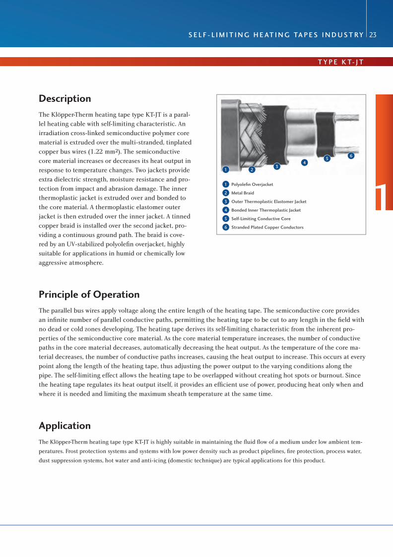
Description The Klöpper-Therm heating tape type KT-JT is a paral-lel heating cable with self-limiting characteristic. An irradiation cross-linked semiconductive polymer core material is extruded over the multi-stranded, tinplated copper bus wires (1.22 mm²). The semiconductive core material increases or decreases its heat output in response to temperature changes. Two jackets provide extra dielectric strength, moisture resistance and pro-tection from impact and abrasion damage. The inner thermoplastic jacket is extruded over and bonded to the core material. A thermoplastic elastomer outer jacket is then extruded over the inner jacket. A tinned copper braid is installed over the second jacket, pro-viding a continuous ground path. The braid is cove-red by an UV-stabilized polyolefi n overjacket, highly suitable for applications in humid or chemically low aggressive atmosphere.
Principle of Operation The parallel bus wires apply voltage along the entire length of the heating tape. The semiconductive core provides an infi nite number of parallel conductive paths, permitting the heating tape to be cut to any length in the fi eld with no dead or cold zones developing. The heating tape derives its self-limiting characteristic from the inherent pro-perties of the semiconductive core material. As the core material temperature increases, the number of conductive paths in the core material decreases, automatically decreasing the heat output. As the temperature of the core ma-terial decreases, the number of conductive paths increases, causing the heat output to increase. This occurs at every point along the length of the heating tape, thus adjusting the power output to the varying conditions along the pipe. The self-limiting effect allows the heating tape to be overlapped without creating hot spots or burnout. Since the heating tape regulates its heat output itself, it provides an effi cient use of power, producing heat only when and where it is needed and limiting the maximum sheath temperature at the same time.
Application The Klöpper-Therm heating tape type KT-JT is highly suitable in maintaining the fl uid fl ow of a medium under low ambient tem-
peratures. Frost protection systems and systems with low power density such as product pipelines, fi re protection, process water,
dust suppression systems, hot water and anti-icing (domestic technique) are typical applications for this product.
1 23
45
6
1 Polyolefi n Overjacket
2 Metal Braid
3 Outer Thermoplastic Elastomer Jacket
4 Bonded Inner Thermoplastic Jacket
5 Self-Limiting Conductive Core
6 Stranded Plated Copper Conductors
1

The specialists for electric heating systems
24
Rating Data of Heating Tapes
dimensions (nominal): width 12.0 mm, thickness 5.8 mmweight: 130 g/mminimum assembly temperature: -40 °Cminimum bending radius: 12 mm at -40 °C
Klöpper-Therm delivers a complete program of terminal boxes, connection and end seal kits for the self-limiting heating tapes type KT-JT.
TypeDesignation
Watt/Meterat 10 °C
Service Voltage
(V AC)
Maximum Length of Heating Tape
(per Branch)
(m)
Maximum Exposure Temperature Permanent
(°C)
Maximum Exposure Temperature Temporary
(°C)
KT23JT 9 230 185 65 85
KT25JT 15 230 155 65 85
KT28JT 25 230 125 65 85
KT210JT 32 230 115 65 85

T y P e K T- J T
R U b R I K 2
The specialists for electric heating systems
s e l f - l I m I T I n g H e aT I n g Ta P e s I n D U s T Ry 25
Circuit Breaker Selection (C-Characteristic):
Remarks:1. The circuit breaker size must be based on minimum start-up temperature, since the inrush current of the heating tapes increases with decreasing ambient temperature.
2. Do not exceed maximum recommended heating tape length per branch, indicated for each type of heating tape. The longer heating tape lengths marked with two stars (**) are only possible by parallel connection of two or several branches (each of these branches must not exceed the recommended heating tape length per branch!) on the breaker. Do not exceed max. recommended length of heating tape indicated in the table.
3. When connecting two or more different wattage heating tapes in parallel on the same breaker, please use the 16 amps column (16A) and divide 16 amps by the maximum heating tape length indicated with reference to the desired minimum start-up temperature. Thus you get an amps/meter value for each type of heating tape. Multiply the length of each heating tape with the derived amps/meter value. The single amp values calculated have to be added up. The added value must not exceed the amperage rating of the breaker.
4. For electrical heating systems, Klöpper-Therm stipulates the use of a residual current device with a residual cur-rent rating not exceeding 300 mA. Residual current devices with a residual current rating of 30 mA should be used preferably.
TypeDesignation
Start-upTemperatur
(°C)
Max. Recommended Heating Tape Length (in Meters) vs. Circuit Breaker Size
16 A 20 A 25 A 32 A
KT23JT +10-5
-20-30
241**192**159143
302**240**199**179
377**300**249**224**
482**384**319**286**
KT25JT +10-5
-20-30
170**135112101
213**169**140126
266**212**175**157**
341**271**225**202**
KT28JT +10-5
-20-30
90746357
113927871
141**1169889
180**148**125114
KT210JT +10-5
-20-30
57484138
72605247
89756559
115968376
1

The specialists for electric heating systems
26
Power Output Rating at 230 V AC
0
5
10
15
20
25
30
35
40
0
Rohrtemperatur in °C
Wat
t /
Met
er
5 10 15 20 25 30 35 40 45 50 55 60 65
KT210JT
KT28JT
KT25JT
KT23JT
Remark: The power rating is valid for applications on insulated steel pipes.
pipe temperature in °C
wat
t/m
eter

f o R s e l f - l I m I T I n g H e aT I n g Ta P e s T y P e K T- J T
R U b R I K 2
The specialists for electric heating systems
C o n n e C T I o n s C o m P o n e n T s 27
CS-1G-KTConnection and End Seal Kit
for direct entry of a self-limiting heating tape type KT in a connection box consisting of: gland M25 with sealing grommet for KT-heating tape, gasket and locknut, 1 connection and 1 end seal, 1 tube of silicone, green/yellow insulation hose for metal braid, wire end sleeves
article no.: 101250
IS-KTInsulation Entry for Heating Tape Type KT
consisting of:gland M25 with sealing grommet for KT-heating tapeand locknut, aluminium plate 0.6mm with hole M25
article no.: 101252
AK-P132-2HZB-1xM25-1V25-2B25-Ex e (CB-3G)Connection Box for Heating Tape
for connecting up to 3 heating tapes via glands type of protection IP 66, polyester, dim. 145x145x71 mm, 8 terminal blocks up to 6mm², 1 x gland M25, 2 x blind plugs M25, 1 x hole M25
article no.: 101633
AK-PC1111-7 3HZBConnection Box for Heating Tape
for connecting up to 3 heating tapes type of protection IP 66, polycarbonate, dim. 110x110x66 mm, 4 series terminals and 2 PE-terminals 4mm², 7 pre-embossments M25/M20
article no.: 101626
1

The specialists for electric heating systems
28
KH2-2Fixation Tape 0.5 m length
1 threaded clamp with lock
article no.: 101821
KH3-2Fixation Tape 1.0 m length
1 threaded clamp with lock
article no.: 101822
BS-110Box Support for Connection Box CB-3G
made of stainless steel, 3-piece, consisting of:supporting plate 145 x 145 mm, stand-off 110 mm,screw set M12
stand-off article no.: 101688supporting plate article no.: 101674screw set article no.: 101691

f o R s e l f - l I m I T I n g H e aT I n g Ta P e s T y P e K T- J T
R U b R I K 2
The specialists for electric heating systems
C o n n e C T I o n s C o m P o n e n T s 29
FT 70Filament Tape
glass fi bre reinforced, chloride-free, up to 70 °C50 m per roll, 15 mm width
article no.: 101818
AT120Aluminium Adhesive Foil
50 μm strong, up to 120 °C, chloride-free50 m per roll, 100 mm width
article no.: 101802
HS 1-1Warning Sign German‘Achtung Elektrische Begleitheizung’
dimensions: 170 x 80 mm
article no.: 100172
1
The specialists for electric heating systems
30
single Wire Plastic Heating Cable
Type TCTeX-H-/TCTeX-l-
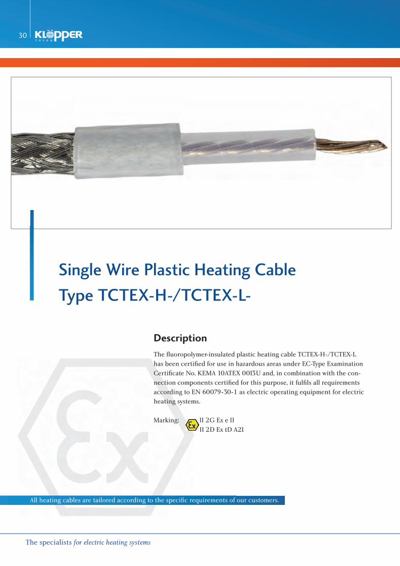
Description The fl uoropolymer-insulated plastic heating cable TCTEX-H-/TCTEX-L has been certifi ed for use in hazardous areas under EC-Type Examination Certifi cate No. KEMA 10ATEX 0013U and, in combination with the con-nection components certifi ed for this purpose, it fulfi ls all requirements according to EN 60079-30-1 as electric operating equipment for electric heating systems.
Marking: II 2G Ex e II II 2D Ex tD A21
All heating cables are tailored according to the specifi c requirements of our customers.

Structure of Plastic-insulated Heating Cable Type TCTEX-H-
Resistance conductor: see table next pageConductor isolation: PFA, wall thickn. 0.80 mm (1) 1.00 mm)Metal braid: Cu-nickel-plated 16 x 5 x 0.15, cross section 1.41 mm² Min. 70% cover: 2) 16 x 5 x 0.20, cross section 2.51 mm² 3) 16 x 6 x 0.20, cross section 3.01 mm²Outer sheath: PFA, wall thickn.: 0.60 mm (4) 0.70 mm) (5) 0.80 mm)
General Characteristics
Resistance at +20 °C: see table next page
Temperature range: -60 °C / +260 °CPower output: max. 30 W/m (actual value accord. to application)Test voltage (U
eff ): 2,50 kV (core/braid)
Nominal voltage (U0/U): 450 V / 750 V
Mechanical stability: 7 Joule, design accord. to EN 60079-30-1Bending radius minimum: 1.08 Ω/km up to 1.71 Ω/km, 25 mm 2.9 Ω/km up to 8.000 Ω/km, 15 mmMin. assembly temperature: -60 °C
T y P e T C T e X- H -
R U b R I K 2
The specialists for electric heating systems
f l U o Ro P o ly m e R- I n s U l aT e D H e aT I n g C a b l e 31
1 resistance conductor
2 conductor isolation
3 metal braid (min. 70% cover)
4 outer sheath
2
12 3
4

The specialists for electric heating systems
32
Technical Data and Type Overview
Article Designation
Resistanceat +20 °C
Ohm/km
Alloy of Conductor
Structure of Conductor
Number x Diameter
Diameter Heating
Conductor
mm2
Cross SectionHeating
Conductormm2
Outer DiameterHeating Cablemm
Temperature Coefficientof Electric Resistance
10-6/K
TCTEX-H -1.08 1) 3) 4) 1.08 Cu-nickel-pltd. 126 x 0.404 5.800 16.00 10.20 +0.2 +4300
TCTEX-H -1.71 3) 4) 1.71 Cu-nickel-pltd. 80 x 0.404 4.600 10.00 8.60 +0.2 +4300
TCTEX-H -2.9 2) 4) 2.9 Cu-nickel-pltd. 84 x 0.300 3.600 6.00 7.60 +0.2 +4300
TCTEX-H -4 2) 4.0 Cu-nickel-pltd. 63 x 0.300 2.750 4.45 6.55 +0.2 +4300
TCTEX-H -4.4 2) 4.4 Cu-nickel-pltd. 56 x 0.300 2.900 4.00 6.70 +0.2 +4300
TCTEX-H -7.2 7.2 Cu-nickel-pltd. 50 x 0.250 1.940 2.50 5.54 +0.2 +4300
TCTEX-H -10 10 Cu-nickel-pltd. 56 x 0.203 1.750 1.81 5.35 +0.2 +4300
TCTEX-H -11.7 11.7 Cu-nickel-pltd. 30 x 0.250 1.600 1.47 5.20 +0.2 +4300
TCTEX-H -15 15 Cu-nickel-pltd. 37 x 0.200 1.420 1.16 5.02 +0.2 +4300
TCTEX-H -17.8 17.8 Cu-nickel-pltd. 32 x 0.200 1.300 1.00 4.90 +0.2 +4300
TCTEX-H -25 25 CuNi 1 7 x 0.423 1.269 0.98 4.87 +0.2 +3000
TCTEX-H -31.5 31.5 CuNi 2 7 x 0.530 1.590 1.54 5.19 +0.2 +1000 up to +1600
TCTEX-H -50 50 CuNi 2 7 x 0.423 1.269 0.98 4.87 +0.2 +1000 up to +1600
TCTEX-H -50 50 CuNi 2 15 x 0.289 1.33 0.98 4.93 +0.2 +1000 up to +1600
TCTEX-H -65 65 CuNi 2 7 x 0.370 1.110 0.75 4.71 +0.2 +1000 up to +1600
TCTEX-H -80 80 CuNi 2 7 x 0.335 1.010 0.62 4.61 +0.2 +1000 up to +1600
TCTEX-H -100 100 CuNi 10 7 x 0.520 1.560 1.48 5.16 +0.2 +350 up to +450
TCTEX-H -100 100 CuNi 2 7 x 0.3 0.90 0.49 4.50 +0.2 +1000 up to +1600
TCTEX-H -150 150 CuNi 10 7 x 0.423 1.269 0.98 4.87 +0.2 +350 up to +450
TCTEX-H -180 180 CuNi 6 7 x 0.32 0.96 0.56 4.56 +0.2 +500 up to +900
TCTEX-H -200 200 CuNi 10 7 x 0.366 1.098 0.73 4.70 +0.2 +350 up to +450
TCTEX-H -320 320 CuNi23Mn 7 x 0.410 1.230 0.92 4.83 +0.2 +180
TCTEX-H -360 360 CuNi 10 7 x 0.273 0.819 0.41 4.42 +0.2 +350 up to +450
TCTEX-H -380 380 CuNi23Mn 7 x 0.376 1.128 0.77 4.73 +0.2 +180
TCTEX-H -480 480 CuNi23Mn 7 x 0.335 1.010 0.62 4.61 +0.2 +180
TCTEX-H -600 600 CuNi23Mn 7 x 0.300 0.900 0.49 4.50 +0.2 +180
TCTEX-H -650 650 CuNi23Mn 7 x 0.288 0.864 0.46 4.46 +0.2 +180
TCTEX-H -700 700 CuNi23Mn 7 x 0.277 0.831 0.42 4.43 +0.2 +180
TCTEX-H -810 810 CuNi 44 7 x 0.329 0.987 0.59 4.59 +0.2 -80 up to +40
TCTEX-H -1000 1000 CuNi 44 7 x 0.296 0.888 0.48 4.49 +0.2 -80 up to +40
TCTEX-H -1440 1440 CuNi 44 7 x 0.246 0.738 0.33 4.34 +0.2 -80 up to +40
TCTEX-H -1750 1750 CuNi 44 9 x 0.200 0.700 0.28 4.40 +0.2 -80 up to +40
TCTEX-H -1750 1750 CuNi 44 7 x 0.224 0.672 0.28 4.27 +0.2 -80 up to +40
TCTEX-H -2000 2000 NiCr30/20 7 x 0.305 0.915 0.51 4.52 +0.2 +300 up to +400
TCTEX-H -3000 3000 NiCr30/20 7 x 0.249 0.747 0.34 4.35 +0.2 +300 up to +400
TCTEX-H -8000 8000 NiCr80/20 7 x 0.155 0.465 0.13 4.07 +0.2 +50 up to +150
Ty p e T C T e X- H -

T y P e T C T e X- l-
R U b R I K 2
The specialists for electric heating systems
f l U o Ro P o ly m e R- I n s U l aT e D H e aT I n g C a b l e 33
Structure of Plastic-insulated Heating Cable Type TCTEX-L-
Resistance conductor: see table next pageConductor isolation: PFA, wall thickn. 0.90 mm (1) 1.00 mm)Metal braid: Cu-nickel-plated 16 x 5 x 0.15, cross section 1.41 mm² Outer sheath: PFA, wall thickn.: 0.40 mm (4) 0.70 mm) (5) 0.80 mm)
General Characteristics
Resistance at +20°C: see table next page
Temperature range: -60 °C / +260 °CPower output: max. 30 W/m (actual value accord. to application)Test voltage (U
eff ): 2,50 kV (core/braid)
Nominal voltage (U0/U): 450 V / 750 V
Mechanical stability: 4 Joule, design accord. to EN 60079-30-1Bending radius minimum: 15 mmMin. assembly temperature: -60 °C
1 resistance conductor
2 conductor isolation
3 metal braid (min. 70% cover)
4 outer sheath
12 3
4
2

T y P e T C T e X- l-
The specialists for electric heating systems
34
Technical Data and Type Overview
Article Designation
Resistanceat +20 °C
*Ohm/km
Alloy of Conductor
Structure of Conductor
Number x Diameter
Diameter Heating
Conductor
mm2
Cross SectionHeating
Conductor
mm2
Outer DiameterHeating Cablemm
Temperature Coefficientof Electric Resistance
10-6/K
TCTEX-L -7.2 7.2 Cu-nickel-pltd. 50 x 0.250 1.940 2.50 4.94 +0.2 +4300
TCTEX-L -10 10 Cu-nickel-pltd. 56 x 0.203 1.750 1.81 4.75 +0.2 +4300
TCTEX-L -11.7 11.7 Cu-nickel-pltd. 30 x 0.250 1.600 1.47 4.60 +0.2 +4300
TCTEX-L -15 15 Cu-nickel-pltd. 37 x 0.200 1.420 1.16 4.42 +0.2 +4300
TCTEX-L -17.8 17.8 Cu-nickel-pltd. 32 x 0.200 1.300 1.00 4.30 +0.2 +4300
TCTEX-L -25 25 CuNi 1 7 x 0.423 1.269 0.98 4.27 +0.2 +3000
TCTEX-L -31.5 31.5 CuNi 2 7 x 0.530 1.590 1.54 4.95 +0.2 +1000 up to +1600
TCTEX-L -50 50 CuNi 2 7 x 0.423 1.269 0.98 4.27 +0.2 +1000 up to +1600
TCTEX-L -50 50 CuNi 2 15 x 0.289 1.33 0.98 4.33 +0.2 +1000 up to +1600
TCTEX-L -65 65 CuNi 2 7 x 0.370 1.110 0.75 4.11 +0.2 +1000 up to +1600
TCTEX-L -80 80 CuNi 2 7 x 0.335 1.010 0.62 4.01 +0.2 +1000 up to +1600
TCTEX-L -100 100 CuNi 10 7 x 0.520 1.560 1.48 4.56 +0.2 +350 up to +450
TCTEX-L -100 100 CuNi 2 7 x 0.3 0.90 0.49 3.90 +0.2 +1000 up to +1600
TCTEX-L -150 150 CuNi 10 7 x 0.423 1.269 0.98 4.27 +0.2 +350 up to +450
TCTEX-L -180 180 CuNi 6 7 x 0.32 0.96 0.56 3.96 +0.2 +500 up to +900
TCTEX-L -200 200 CuNi 10 7 x 0.366 1.098 0.73 4.10 +0.2 +350 up to +450
TCTEX-L -320 320 CuNi23Mn 7 x 0.410 1.230 0.92 4.23 +0.2 +180
TCTEX-L -360 360 CuNi 10 7 x 0.273 0.819 0.41 3.82 +0.2 +350 up to +450
TCTEX-L -380 380 CuNi23Mn 7 x 0.376 1.128 0.77 4.13 +0.2 +180
TCTEX-L -480 480 CuNi23Mn 7 x 0.335 1.010 0.62 4.01 +0.2 +180
TCTEX-L -600 600 CuNi23Mn 7 x 0.300 0.900 0.49 3.90 +0.2 +180
TCTEX-L -650 650 CuNi23Mn 7 x 0.288 0.864 0.46 3.87 +0.2 +180
TCTEX-L -700 700 CuNi23Mn 7 x 0.277 0.831 0.42 3.83 +0.2 +180
TCTEX-L -810 810 CuNi 44 7 x 0.329 0.987 0.59 3.99 +0.2 -80 up to +40
TCTEX-L -1000 1000 CuNi 44 7 x 0.296 0.888 0.48 3.89 +0.2 -80 up to +40
TCTEX-L -1440 1440 CuNi 44 7 x 0.246 0.738 0.33 3.74 +0.2 -80 up to +40
TCTEX-L -1750 1750 CuNi 44 9 x 0.200 0.700 0.28 3.70 +0.2 -80 up to +40
TCTEX-L -1750 1750 CuNi 44 7 x 0.224 0.672 0.28 3.76 +0.2 -80 up to +40
TCTEX-L -2000 2000 NiCr30/20 7 x 0.305 0.915 0.51 3.92 +0.2 +300 up to +400
TCTEX-L -3000 3000 NiCr30/20 7 x 0.249 0.747 0.34 3.75 +0.2 +300 up to +400
TCTEX-L -8000 8000 NiCr30/20 7 x 0.155 0.465 0.13 3.47 +0.2 +50 up to +150

e x- C o n n e C T I o n s l e e V e T y P e P T f e e X 7025
R U b R I K 2
The specialists for electric heating systems
C o n n e C T I o n C o m P o n e n T s 35
ex-Connection sleeve
Type PTfe ex 7025
EC – Type Examination Certifi cate BVS 05 ATEX E 031X > Universal, that means to be used independently from manufacturer for EC-type-examined
single-core polymer-insulated heating cables with a conductor cross section of max. 2.5 mm² > Usable as Ex-connection sleeve for connecting heating cable with cold cable or
as Ex-transition sleeve for connecting heating cable with heating cable > Connection of conductors and braids via crimp connections by using nickel-plated parallel connectors > Inside silicone seal plugs preventing intrusion of water and dust > Heating cable diameter: max. 6.4 mm, min. 3.8 mm > Temperature range: -40 °C up to +200 °C > Rated voltage: max. 750 V > Rated current: max. 32 A > Type of protection: IP67 > Materials: sleeve body: PTFE, seal plugs: silicone, locking rings: stainless steel > Dimensions: Ø 30.5 mm, length 132 mm> Marking: II 2G Ex e II –40 °C Tp +200 °C II 2D Ex tD A21 IP67 –40 °C Tp +200 °C
article no.: 100967
2
e x- C o n n e C T I o n s l e e V e T y P e P T f e e X 716 0
The specialists for electric heating systems
36
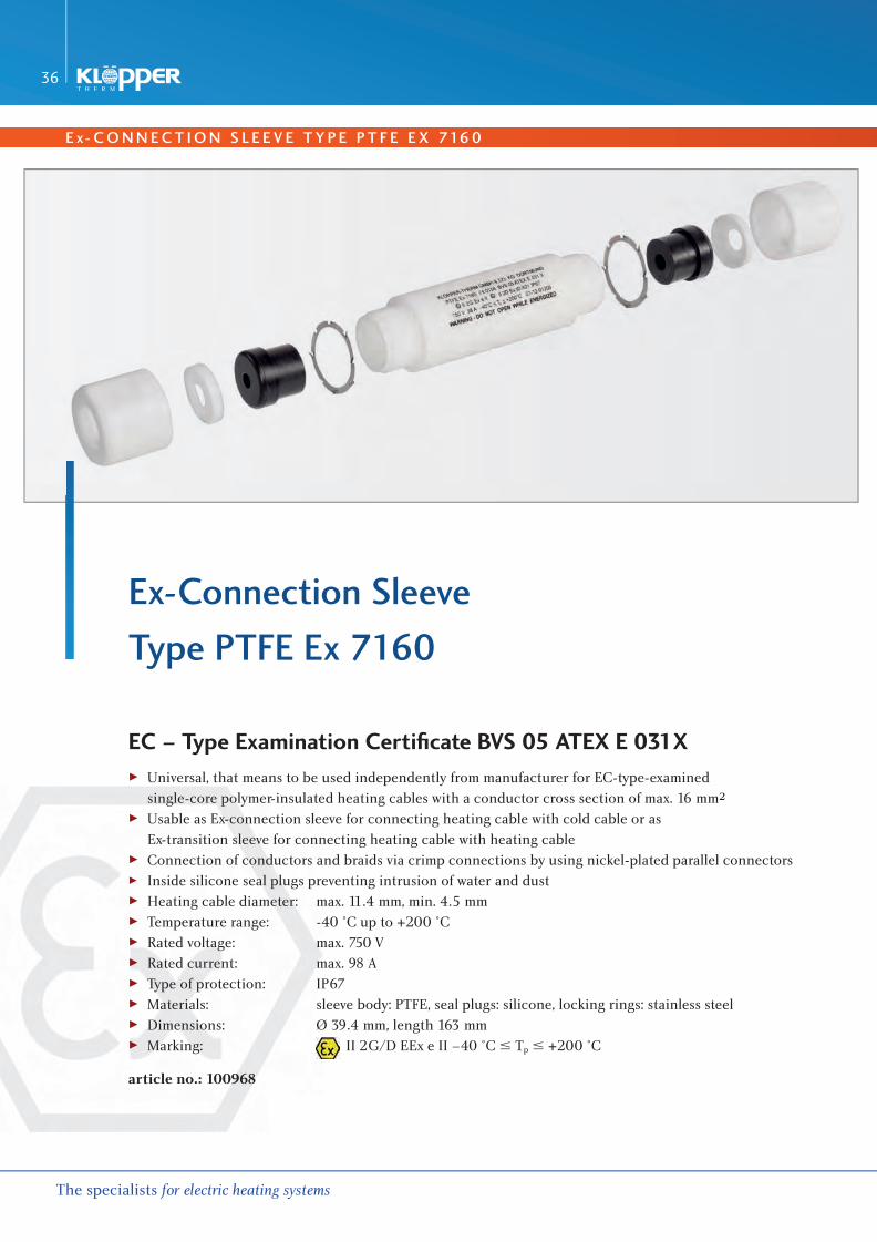
ex-Connection sleeve
Type PTfe ex 7160
EC – Type Examination Certifi cate BVS 05 ATEX E 031X > Universal, that means to be used independently from manufacturer for EC-type-examined
single-core polymer-insulated heating cables with a conductor cross section of max. 16 mm² > Usable as Ex-connection sleeve for connecting heating cable with cold cable or as
Ex-transition sleeve for connecting heating cable with heating cable > Connection of conductors and braids via crimp connections by using nickel-plated parallel connectors > Inside silicone seal plugs preventing intrusion of water and dust > Heating cable diameter: max. 11.4 mm, min. 4.5 mm > Temperature range: -40 °C up to +200 °C > Rated voltage: max. 750 V > Rated current: max. 98 A > Type of protection: IP67 > Materials: sleeve body: PTFE, seal plugs: silicone, locking rings: stainless steel> Dimensions: Ø 39.4 mm, length 163 mm> Marking: II 2G/D EEx e II –40 °C Tp +200 °C
article no.: 100968

T y P e T C T e x
R U b R I K 2
The specialists for electric heating systems
f l U o Ro P o ly m e R- I n s U l aT e D H e aT I n g C a b l e 37
fluoropolymer-insulated Heating Cable
for Frost Protection and Process Temperatures
Type Resistance Art.-No.
TCTEX-H-8000 8.00 Ω/m 100912
TCTEX-H-3000 3.00 Ω/m 100911
TCTEX-H-2000 2.00 Ω/m 100910
TCTEX-H-1750* 1.75 Ω/m 100907
TCTEX-H-1440 1.44 Ω/m 100906
TCTEX-H-1000 1.00 Ω/m 100905
TCTEX-H-810 0.81 Ω/m 100904
TCTEX-H-700 0.70 Ω/m 100903
TCTEX-H-650* 0.65 Ω/m 100902
TCTEX-H-600* 0.60 Ω/m 100901
TCTEX-H-480 0.48 Ω/m 100900
TCTEX-H-380 0.38 Ω/m 100899
TCTEX-H-360 0.36 Ω/m 100898
TCTEX-H-320 0.32 Ω/m 100897
TCTEX-H-200 0.20 Ω/m 100896
TCTEX-H-180* 0.18 Ω/m 100895
TCTEX-H-150 0.15 Ω/m 100894
Type Resistance Art.-No.
TCTEX-H-100 0.10 Ω/m 100892
TCTEX-H-80 0.080 Ω/m 100891
TCTEX-H-65 0.065 Ω/m 100890
TCTEX-H-50 0.050 Ω/m 100888
TCTEX-H-31.5 0.0315 Ω/m 100887
TCTEX-H-25 0.025 Ω/m 100886
TCTEX-H-17.8 0.0178 Ω/m 100885
TCTEX-H-15 0.015 Ω/m 100884
TCTEX-H-11.7* 0.0117 Ω/m 100883
TCTEX-H-10 0.010 Ω/m 100882
TCTEX-H-7.2 0.0072 Ω/m 100881
TCTEX-H-4.4 0.0044 Ω/m 100880
TCTEX-H-4.0* 0.0040 Ω/m 100879
TCTEX-H-2.9 0.0029 Ω/m 100878
TCTEX-H-1.71* 0.00171 Ω/m 100877
TCTEX-H-1.08* 0.00171 Ω/m 100876
1 2 3 41 resistance conductor
2 conductor isolation
3 metal braid
4 outer sheath
conductor isolation: PFA >= 0,7mmouter sheath: PFA >= 0,5mmtemperature range: up to 250 °C / max. 30 W/mnominal voltage: 450 / 750V
* only on request
2

The specialists for electric heating systems
38
TCT-Ex Cold CableFluoropolymer-insulated
TCT-Ex-H-7,2-100, 2.5 mm², 1 m lengtharticle no.: 100926
TCT-Ex-H-7,2-100, 2.5 mm², 2 m lengtharticle no.: 100927
TCT-Ex-H-2,9-150, 6 mm², 1.5 m lengtharticle no.: 100925
TCT-Ex-1,71-150, 10 mm², 1.5 m lengtharticle no.: 112918
other lengths and cross sections possible
PTFE Ex 7025Ex-connection Sleeve for ATEX
certifi ed polymer-insulated heating cableup to 2.5 mm², 32 A max
article no.: 100967
PTFE Ex 7160Ex-connection Sleeve for ATEX
certifi ed polymer-insulated heating cableup to 16 mm², max. 98 A
article no.: 100968

T y P e T C T e x
R U b R I K 2
The specialists for electric heating systems
f l U o Ro P o ly m e R- I n s U l aT e D H e aT I n g C a b l e 39
CSL 20025Connection Sleeve for Non-hazardous Area
in shrinking techniquetemperature range up to 200 °C
article no.: 100929
CSL 8025Connection Sleeve for Non-hazardous Area
in shrinking techniquetemperature range up to 80 °C
article no.: 100928
AK-P132-2TCT-2VM16-1VM25-1BM25-Ex eConnection Box EEx e
for connecting a TCT-Ex-heating loop, polyester, type of protection IP66, dim. 145x145x71 mm, 6 terminal blocks up to 6 mm², 1 x EEx e gland M25, 1 x EEx e seal plug M25, 2 x gland M16
article no.: 101636
AK-P051-6TCT-6V16-1V25-1B25-Ex eConnection Box EEx e
for connecting up to 3 TCT-Ex-heating loops, polyester, type of protection IP66, dim. 170x170x91 mm, 8 terminal blocks + 4 PE-terminals 4 mm², 1 x EEx e gland M25, 1 x EEx e seal plug M25, 6 x gland M16
article no.: 116907
Remark: Other box sizes and equipment as well as design for industrial application possible.
2

KH2-2Fixation Tape 0.5 m Length
1 threaded clamp with lock
article no.: 101821
KH3-2Fixation Tape 1.0 m Length
1 threaded clamp with lock
article no.: 101822
KH5-8Fixation Tape 1.0 m Length
1 stainless steel tightening strap with lock 5/8“ (tightening tool required)
article no.: 101820
The specialists for electric heating systems
40
BS-110Box Support for Connection Box CB-TCT-Ex-1L
made of stainless steel, 3-piece, consisting of: supporting plate 145 x 145 mm, stand-off 110 mm, screw set M12
stand-off article no.: 101688supporting plate article no.: 101674screw set article no.: 101691
BS-170Box Support for Connection Box CB-TCT-Ex-3L
made of stainless steel, 3-piece, consisting of: supporting plate 170 x 170 mm, stand-off 110 mm, screw set M12
stand-off article no.: 101677supporting plate article no.: 101674screw set article no.: 101691

T y P e T C T e x
R U b R I K 2
The specialists for electric heating systems
f l U o Ro P o ly m e R- I n s U l aT e D H e aT I n g C a b l e 41
HS 1-1Warning Sign German‘Achtung Elektrische Begleitheizung’
dimensions: 170 x 80 mm
article no.: 100172
HS 1-2Warning Sign English / French‘Attention Electrical Tracing’‘Attention Tracage Électrique’
dimensions: 150 x 70 mm
article no.: 100174
HS 1-3Warning Sign Russian‘ОСТОРОЖНО! ЭЛЕКТРИЧЕСКИЙ КАБЕЛЬНЫЙ НАГРЕВ’
dimensions: 150 x 70 mm
article no.: 100173
2

The specialists for electric heating systems
42
FT 70Filament Tape
glass fi bre reinforced, chloride-free, up to 70 °C50 m per roll, 15 mm width
article no.: 101818
FT 130Filament Tape
glass fi bre reinforced, chloride-free, up to 130 °C50 m per roll, 15 mm width
article no.: 101819
GT 180Glass fi bre Tape
chloride-free, up to 180 °C50 m per roll, 15 mm width
article no.: 101814
AT120Aluminium Adhesive Foil
50 μm strong, up to120 °C, chloride-free50 m per roll, 100 mm width
article no.: 101802
AT150Aluminium Adhesive Foil
100 μm strong, up to 150 °C, chloride-free50 m per roll, 65 mm width
article no.: 101803
T y P e T C T e x
R U b R I K 2
The specialists for electric heating systems
f l U o Ro P o ly m e R- I n s U l aT e D H e aT I n g C a b l e 43
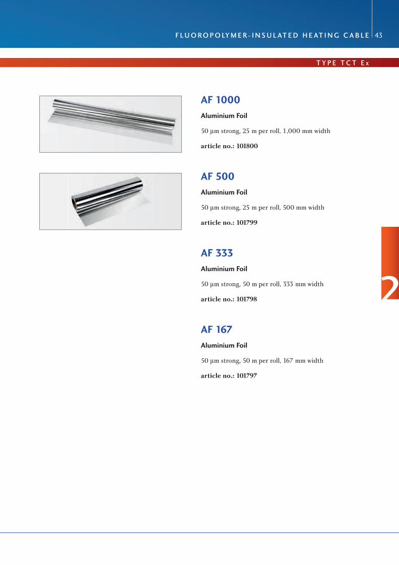
AF 1000Aluminium Foil
50 μm strong, 25 m per roll, 1,000 mm width
article no.: 101800
AF 500Aluminium Foil
50 μm strong, 25 m per roll, 500 mm width
article no.: 101799
AF 333Aluminium Foil
50 μm strong, 50 m per roll, 333 mm width
article no.: 101798
AF 167Aluminium Foil
50 μm strong, 50 m per roll, 167 mm width
article no.: 101797
2

The specialists for electric heating systems
44
Description The mineral-insulated heating cables type KT * *** * x * * have been certi-fi ed under type examination certifi cate no. BVS 05 ATEX E 158 U for use in hazardous area, created by gases and dusts and, in combination with the connection components certifi ed, they fulfi l all requirements according to EN 60079-0:2006, EN 60079-30-1:2007, EN 61241-0:2006 and EN 61241-1:2004 as electric operating equipment for electric heating systems. The electric heating systems are subject to the EC-type examination certifi cate no. BVS 05 ATEX E 161 X.
Mineral-insulated heating cables are also offered as sleeve joint ex works. This offers the advantage to use highly temperature-resistant, welded sleeves
mineral-insulted Heating Cables
Type KT * *** *x* *
All our heating cables are tailored according to the specifi c requirements of our customers.

T y P e o V e RV I e W
R U b R I K 2
The specialists for electric heating systems
m I n e R a l- I n s U l aT e D H e aT I n g C a b l e 45
Resistance conductor: see table next pagesIsolation: magnesium oxide MgOSheath material: copper-nickel, max. operating temperature 400 °C stainless steel in different material quality grades with max. operating temperatures up to 850 °CCoating (optional): different plastic coatings (corrosion protection), coating thickness from 0.5 to 1.5 mm
General Characteristics
Resistance at +20 °C: see attachment of datasheet MI-heating cableInstallation temperature: min. -40 °CTemperature range: min. -60 °C up to 850 °C max. (see pos 5.)Test voltage (U
eff): 2U + 1000 volt (core/braid)
Rated voltage (U): 300 V or 400 V see following pages (between outer sheath and conductor)Mechanical stability: 7 joule, design according to EN 60079-30-1:2007Bending radius minimum: 5fold outer diameterPower output: max. 200 W/m (actual value according to application)
12
341 Resistance conductor
2 Isolation
3 Sheath material
4 Coating (Optional)
Structure of MI-Heating Cables
3
The specialists for electric heating systems
46
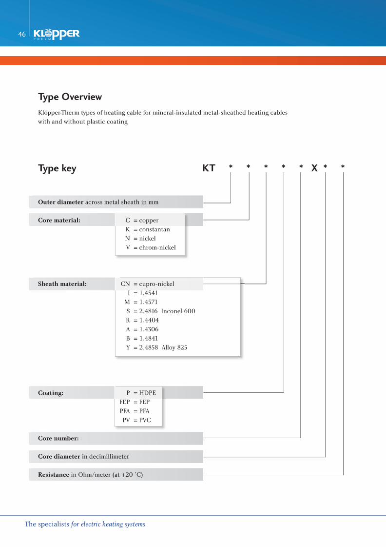
Type Overview Klöpper-Therm types of heating cable for mineral-insulated metal-sheathed heating cables with and without plastic coating
Type key KT * * * * * X * *
Outer diameter across metal sheath in mm
Core material: C = copper K = constantan N = nickel V = chrom-nickel
Sheath material: CN = cupro-nickel I = 1.4541 M = 1.4571 S = 2.4816 Inconel 600 R = 1.4404 A = 1.4306 B = 1.4841 Y = 2.4858 Alloy 825
Coating: P = HDPE FEP = FEP PFA = PFA PV = PVC
Core number:
Core diameter in decimillimeter
Resistance in Ohm/meter (at +20 °C)
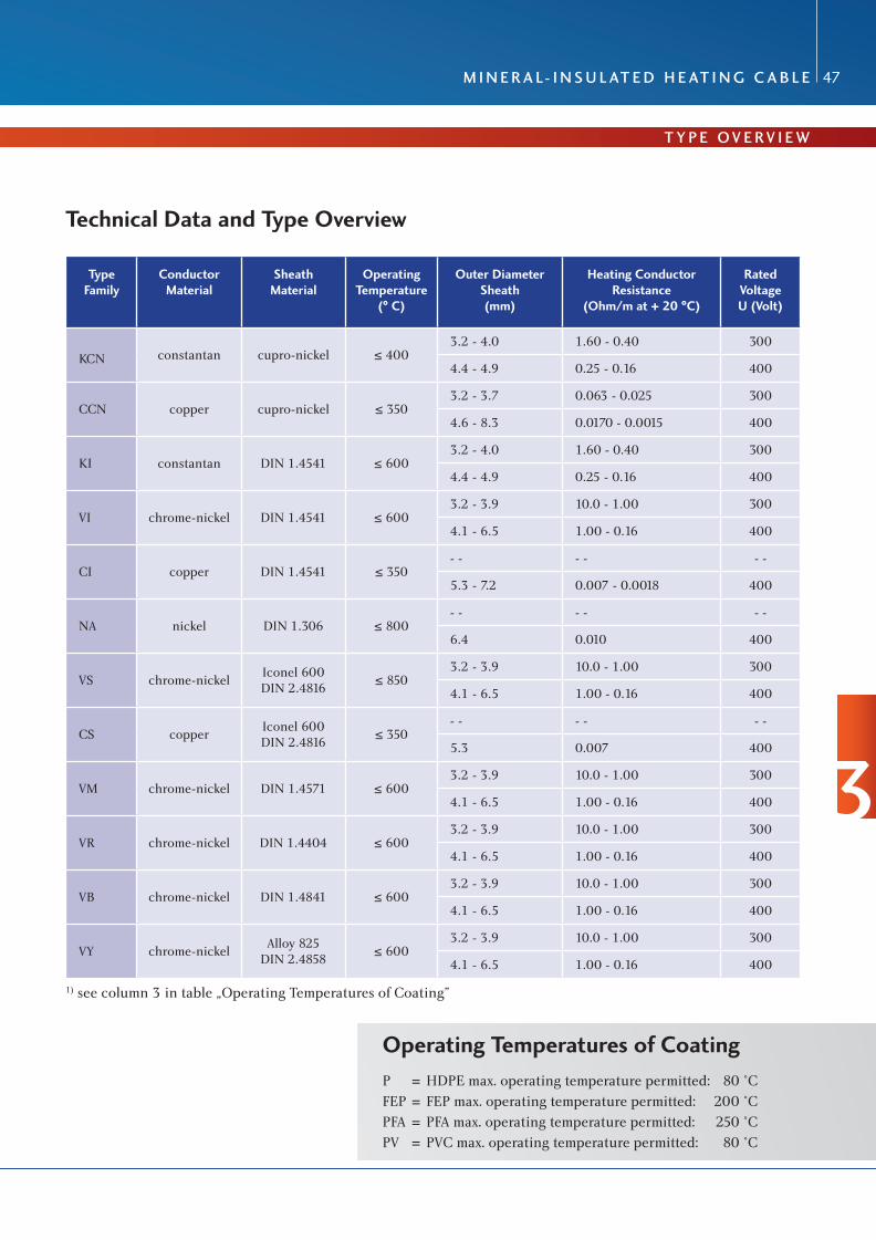
Technical Data and Type Overview
Type Family
Conductor Material
Sheath Material
Operating Temperature
(° C)
Outer Diameter Sheath (mm)
Heating Conductor Resistance
(Ohm/m at + 20 °C)
Rated Voltage U (Volt)
KCN constantan cupro-nickel ≤ 4003.2 - 4.0 1.60 - 0.40 300
4.4 - 4.9 0.25 - 0.16 400
CCN copper cupro-nickel ≤ 3503.2 - 3.7 0.063 - 0.025 300
4.6 - 8.3 0.0170 - 0.0015 400
KI constantan DIN 1.4541 ≤ 6003.2 - 4.0 1.60 - 0.40 300
4.4 - 4.9 0.25 - 0.16 400
VI chrome-nickel DIN 1.4541 ≤ 6003.2 - 3.9 10.0 - 1.00 300
4.1 - 6.5 1.00 - 0.16 400
CI copper DIN 1.4541 ≤ 350- - - - - -
5.3 - 7.2 0.007 - 0.0018 400
NA nickel DIN 1.306 ≤ 800- - - - - -
6.4 0.010 400
VS chrome-nickelIconel 600DIN 2.4816
≤ 8503.2 - 3.9 10.0 - 1.00 300
4.1 - 6.5 1.00 - 0.16 400
CS copperIconel 600DIN 2.4816
≤ 350- - - - - -
5.3 0.007 400
VM chrome-nickel DIN 1.4571 ≤ 6003.2 - 3.9 10.0 - 1.00 300
4.1 - 6.5 1.00 - 0.16 400
VR chrome-nickel DIN 1.4404 ≤ 6003.2 - 3.9 10.0 - 1.00 300
4.1 - 6.5 1.00 - 0.16 400
VB chrome-nickel DIN 1.4841 ≤ 6003.2 - 3.9 10.0 - 1.00 300
4.1 - 6.5 1.00 - 0.16 400
VY chrome-nickelAlloy 825
DIN 2.4858≤ 600
3.2 - 3.9 10.0 - 1.00 300
4.1 - 6.5 1.00 - 0.16 400
T y P e o V e RV I e W
R U b R I K 2
The specialists for electric heating systems
m I n e R a l- I n s U l aT e D H e aT I n g C a b l e 47
1) see column 3 in table „Operating Temperatures of Coating”
Operating Temperatures of Coating P = HDPE max. operating temperature permitted: 80 °CFEP = FEP max. operating temperature permitted: 200 °CPFA = PFA max. operating temperature permitted: 250 °CPV = PVC max. operating temperature permitted: 80 °C
3
The specialists for electric heating systems
48
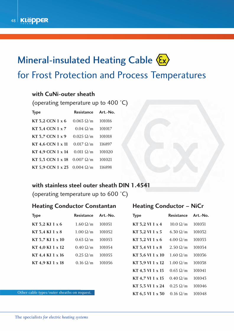
mineral-insulated Heating Cable
for Frost Protection and Process Temperatures
with CuNi-outer sheath (operating temperature up to 400 °C)Type Resistance Art.-No.
KT 3,2 CCN 1 x 6 0.063 Ω/m 101016
KT 3,4 CCN 1 x 7 0.04 Ω/m 101017
KT 3,7 CCN 1 x 9 0.025 Ω/m 101018
KT 4,6 CCN 1 x 11 0.017 Ω/m 116897
KT 4,9 CCN 1 x 14 0.011 Ω/m 101020
KT 5,3 CCN 1 x 18 0.007 Ω/m 101021
KT 5,9 CCN 1 x 23 0.004 Ω/m 116898
with stainless steel outer sheath DIN 1.4541(operating temperature up to 600 °C)
Heating Conductor Constantan Heating Conductor – NiCrType Resistance Art.-No. Type Resistance Art.-No.
KT 3,2 KI 1 x 6 1.60 Ω/m 101051 KT 3,2 VI 1 x 4 10.0 Ω/m 101031
KT 3,4 KI 1 x 8 1.00 Ω/m 101052 KT 3,2 VI 1 x 5 6.30 Ω/m 101032
KT 3,7 KI 1 x 10 0.63 Ω/m 101053 KT 3,2 VI 1 x 6 4.00 Ω/m 101033
KT 4,0 KI 1 x 12 0.40 Ω/m 101054 KT 3,4 VI 1 x 8 2.50 Ω/m 101034
KT 4,4 KI 1 x 16 0.25 Ω/m 101055 KT 3,6 VI 1 x 10 1.60 Ω/m 101036
KT 4,9 KI 1 x 18 0.16 Ω/m 101056 KT 3,9 VI 1 x 12 1.00 Ω/m 101038
KT 4,3 VI 1 x 15 0.63 Ω/m 101041
KT 4,7 VI 1 x 15 0.40 Ω/m 101043
KT 5,3 VI 1 x 24 0.25 Ω/m 101046
KT 6,5 VI 1 x 30 0.16 Ω/m 101048Other cable types/outer sheaths on request.

R U b R I K 2
The specialists for electric heating systems
m I n e R a l- I n s U l aT e D H e aT I n g C a b l e 49
mineral-insulated Cold Cable
KT 5,3 CI 1x18, 2.5 mm², 1 m length including connection, gland M20outer sheath: stainless steel
article no.: 101189
KT 5,3 CI 1x18, 2.5 mm², 2 m length including connection, gland M20outer sheath: stainless steel
article no.: 101190
KT 5,3 CC 1x18, 2.5 mm², 1 m length including connection, gland M20outer sheath: CU
article no.: 101180
KT 6,4 CC 1x28.6 mm², 1 m length including connection, gland M20outer sheath: CU
article no.: 101181
3

The specialists for electric heating systems
50
Connection SleevesEx-connection sleeve 3-piece
for mineral-insulated heating cable stainless steel, adapted to the particular cross section of heating and cold cableapplication temperature 300 °C
article no.: 1010xxx - 1011xxxdifferent cable sizes on request.
Ex-connection sleeve 1-piece
for mineral-insulated heating cable CU, adapted to the particular cross section of heating and cold cable
article no.: 101084 (for transition sleeves)
AK-P132-2MI-2xM20-1VM25-1BM25-EX e (CB-MI-Ex-1L)Connection Box EEx e
for connecting a TCT-Ex-heating loop polyester, type of protection IP66, dim. 145x145x71 mm, 6 terminal blocks up to 6 mm², 1 x EEx e gland M25, 1 x EEx e blind plug M25, 2 x hole M20
article no.: 101635
AK-P051-6MI-1V25-6B20-1S25-EX e (CB-MI-Ex-3L)Connection Box EEx e
for connecting up to 3 MI-Ex-heating loops polyester, type of protection IP66, dim. 170x170x91 mm, 8 terminal blocks + 4 PE-terminals 4 mm², 1 x EEx e gland M25, 1 x EEx e blind plug M25, 6 x hole M20
article no.: 116909
Other box sizes and equipment as well as design for industrial application possible.

R U b R I K 2
The specialists for electric heating systems
m I n e R a l- I n s U l aT e D H e aT I n g C a b l e 51
KH2-2Fixation Tape 0.5 m length
1 threaded clamp with lock
article no.: 101821
KH3-2Fixation Tape 1.0 m length
1 threaded clamp with lock
article no.: 101822
KH5-8Fixation Tape 1.0 m length
1 stainless steel tightening strap with lock 5/8“(tightening tool required)
article no.: 101820
BS-110Box Support for Connection Box CB-MI-Ex-1L
made of stainless steel, 3-piece, consisting of: supporting plate 145x145 mm, stand-off 110 mm, screw set M12
stand-off article no.: 101688supporting plate article no.: 101674screw set article no.: 101691
BS-160Box Support for Connection Box CB-TCT-Ex-3L
made of stainless steel, 3-piece, consisting of:supporting plate 145 x 145 mm, stand-off 160 mm,screw set M12
stand-off article no.: 101689supporting plate article no.: 101674screw set article no.: 101691
3

The specialists for electric heating systems
52
FT 3-8Stainless Steel Tightening Strap 3/8“, 90 m/rl.for fi xation of heating cables
article no.: 101808
FT 5-8Stainless Steel Tightening Strap 5/8“, 30 m/rl.for fi xation of heating cables
article no.: 101809
FL 3-8Stainless Steel Tightening Strap 3/8“, 100 pcs./PE.for fi xation of heating cables
article no.: 101810
FL 5-8Stainless Steel Tightening Strap 5/8“, 100 pcs./PE.for fi xation of heating cables
article no.: 101811
MT 5-8Stainless Steel Assembly Tape 5/8“ 20 m/rl.strap distance 40 mm, for fi xation of heating cables
article no.: 101825
WHA 001Tightening Toolfor FT/MT
article no.: 103758

R U b R I K 2
The specialists for electric heating systems
m I n e R a l- I n s U l aT e D H e aT I n g C a b l e 53
HS 1-1Warning Sign German‘Achtung Elektrische Begleitheizung’
dimensions: 170 x 80 mm
article no.: 100172
HS 1-2Warning Sign English / French‘Attention Electrical Tracing’
Dimension: 150 x 70 mm
article no.: 100174
HS 1-3Warning Sign Russian‘ОСТОРОЖНО! ЭЛЕКТРИЧЕСКИЙ КАБЕЛЬНЫЙ НАГРЕВ’
Dimension: 150 x 70 mm
article no.: 100173
C o n n e C T I o n s C o m P o n e n T s
3

The specialists for electric heating systems
54
AF 1000Aluminium Foil 50 μm strong, 25 m per roll, 1,000 mm width
article no.: 101800
AF 500Aluminium Foil 50 μm strong, 50 m per roll, 500 mm width
article no.: 101799
AF 333Aluminium Foil 50 μm strong, 50 m per roll, 333 mm width
article no.: 101798
AF 167Aluminium Foil 50 μm strong, 50 m per roll, 167 mm width
article no.: 101797
SF 1000Stainless Steel Foil Material 1.4301,1,000 mm width, 25 m per roll
article no.: 101805
SF 100Stainless Steel Foil Material 1.4301 100 mm width, 25 m per roll
article no.: 101806
SF 200Stainless Steel Foil Material 1.4301 200 mm width, 25 m per roll
article no.: 101807

R U b R I K 2
The specialists for electric heating systems
C o n T Ro l T e C H n I q U e 55
U n I P l e X I I I
article no.: 113143
CONTROL
UNIPLEX III – Powerful control for heating systems
The latest release of the Klöpper-Therm heating controller UNIPLEX again convinces by development competence and trendsetting technology within one device. Especially designed for the control and monitoring of electric heating systems, several function modules have been combined in one device. Temperature controller, safety temperature limiter and current controller have been placed on a space-saving 19”-rack mounting in Eurocard size.
The main features:> high safeness by safety temperature limiter (STB), certified according to ATEX and classified as Safety Integrity Level SIL 2> configurable as PI- or two-position controller> continuous control of heating circuits by driving a solid state relay (SSR) > integrated current controller (pulse-width- modulation) for adjusting the desired heating current (reduces the number of heating cable types or resistance types used)> customized adaption of heating current to variable maintenance temperatures> large display indicating nominal, actual and control value (control value as bar graph)
> comfortable operating menu in different languages (language selection)> serial RS-485 interface and Ethernet interface for connection to higher control systems> front USB connection for diagnosis/configuration> password-protected access on three levels> reset of limiter by tool/code entry> various limit value monitoring for temperature and current> automatic self-testing> extended application possibilities by additional controller sensor and limiter sensor > connection of 4–20 mA sensor or set point encoder
4

The specialists for electric heating systems
56
UNIPLEX III – Technical Data
Dimensions> 19”-rack mounting Front panel 8 HP (40.64 mm) wide, 3 HE (133.35 mm) high Printed Circuit Board Eurocard size 100 x 160mm Connector 48-pin female in model F
Ambient conditions> Ambient temperature 0 °C to +50 °C in operation, -20 °C to +70 °C during storage > Relative humidity < 95 % at 30 °C, non-condensing
Power supplyThe power supply takes place via a switch mode converter with a transformer, which ensures the electrical decoupling of the assembly.> Voltage supply 24 V DC 6 20%, ripple max. 1V
PP
> Power consumption typically 3 W> Mains failure bridging > 20 ms, otherwise automatic reset
Input for temperature measuring sensor Pt100 in 3-wire circuit> Measuring range -200 °C to +650 °C > Resolution 1K in the range -200 °C to +650 °C> Measuring tolerance 61K up to +300 °C, 63K up to +650 °C > Sensor current 1 mA (kept constant via current source)
Input for current converterThe input is electrically decoupled by means of a magnetic measuring transformer. > Measuring range 0mA to 100mA > Conversion factor 1 : 10 up to 1 : 1000 freely adjustable> Input resistance (burden) 50 ohms > maximum permissible input voltage 67 V
PP
> True-RMS measurement approx. 1000 samples/s
Control output for heating contactor and solid state relay> connected output voltage 24 V DC against GND > maximum current load approx. 1000 mA, self-limiting
Relay outputs for software-selectable messages> 1-pin NO contact, closed circuit principle
> Switching capacity 24 V DC, 1 A, 30 W bzw. 24 V AC, 1 A, 30 VA
Potential-free inputs for software-selectable signalsExternal voltage signal, voltage present = input active > max. permissible input voltage 24 V DC> min. necessary input current 10 mA

R U b R I K 2
The specialists for electric heating systems
C o n T Ro l T e C H n I q U e 57
U n I P l e X I I I
Temperature Controller
> On-off controller (contact) and P-controller (output to current controller)> Supervision regarding low and excess temperature> Sensor connection Pt 100 in three-wire connection> Supervision of the temperature sensor regarding cable break and short circuit> Current measuring input for connecting an external current transformer> Real measurement of current-effective value> Signal output for triggering a solid state relay according to the full wave switch mode> Supervision of the load circuit regarding under- and overcurrent incl. signalling> Error message via potential-free contacts> Memory of the error status even in case of a decline in voltage.> Controller to be switched off by keyboard entry or by an external signal, the limiter continues operation with all functions.> Processing of an external limiter signal for triggering off the internal limiter and for switching off the output signals of the controller.> Standstill control> Suppression of low temperature message in case of start-up operations> Switching off the controller after internal/external limiter has triggered off, sensor fault and overcurrent.
LCD-Display and Keyboard
LCD-display for plain text output of:> parameter names> parameter values> error messages in ‘plain text’ > controller/limiter actual value> controller/limiter setpoint> current actual value> current setpoint - adjustment of HC number (HC heating circuit)> adjustments hardware addressKeyboard for:> entry of setpoints> parameter setting of controller> selection of displayPassword-protected parameter entryIndication of operating and error status via light-emitting diodes 4

The specialists for electric heating systems
58
Serial Interface: > Connection via serial data bus to a PC (RS485 norm) or via Ethernet TCP/IP interface to a network. In addition
the UNIPLEX can be attached to nearly all process control systems by a separate Profibus-coupler.> Adjustment of all setpoints at the PC possible.> Transfer of all measuring values, parameter, error messages and the controller state to the PC.> Mutual locking for operating from the PC or the front panel of the UNIPLEX II card.> Password locking for changing the parameter and acknowledging errors.> Detailed and comfortable parameter and status recording at the PC.> Connection length up to approx. 800 m (standard RS485) or connection to a network available (Ethernet TCP/IP
or Profibus).> Installation of the UNIPLEX II- cards in the decentralised switchgear, operation and display in the central con-
trol station at the PC.
Ethernet TCP/IP- Interface:
> Connection via an Ethernet network to a PC, TCP/IP report, 10Mbit/s.> Adjustment of all setpoints at the PC possible, transfer of all measuring values, parameter, error messages and controller states to the PC.> ‘Control’ for the data transfer to a visualisation system (OPC- Control) available (for each UNIPLEX II one ‘Control’ has to be installed).
> ‘Control’ for the direct communication of a PC with a UNIPLEX II available.
Connection of Measuring Sensor:
> Pt100 measuring sensor, EEx d or EEx e; three-wire connection in hazardous area> Pt100 measuring sensor, EEx i via process signal isolator, three-wire connection in hazardous area.> Pt100 standard measuring sensor in 2- or 3-wire connection for all other applications in non-hazardous area.

R U b R I K 2
The specialists for electric heating systems
C o n T Ro l T e C H n I q U e 59
U n I P l e X I I I
Sample Wiring Diagram UNIPLEX IIBraided cables have to be used, a one-sided earthing of the braid is necessary!
4

The specialists for electric heating systems
60
V I SUA L I S I E RUNG
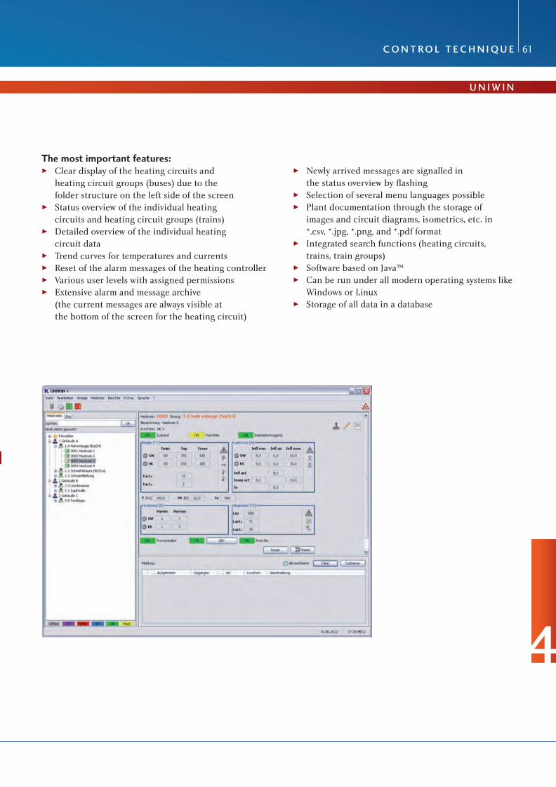
UNIWIN – The convenient software cockpit for heating controllers
The UNIWIN visualisation software guarantees the clear display and convenient operation of the UNIPLEX III heating controllers and offers access to the current status of the heating circuits within the system. Electrical heating plants that consist of a number of individual electrical heating systems can be configured into logical process-engineering groups using the UNIWIN software. The plant structure can be assigned to these groups. For a perfect overview, all important heating circuit and plant data, the status overview, and a message archive with various sorting and selection functions are always available for access on the computer.
R U b R I K 2
The specialists for electric heating systems
C o n T Ro l T e C H n I q U e 61
U n I W I n
The most important features:> Clear display of the heating circuits and heating circuit groups (buses) due to the folder structure on the left side of the screen> Status overview of the individual heating circuits and heating circuit groups (trains)> Detailed overview of the individual heating circuit data> Trend curves for temperatures and currents> Reset of the alarm messages of the heating controller> Various user levels with assigned permissions> Extensive alarm and message archive (the current messages are always visible at the bottom of the screen for the heating circuit)
> Newly arrived messages are signalled in the status overview by flashing> Selection of several menu languages possible> Plant documentation through the storage of images and circuit diagrams, isometrics, etc. in *.csv, *.jpg, *.png, and *.pdf format> Integrated search functions (heating circuits, trains, train groups)> Software based on Java™> Can be run under all modern operating systems like Windows or Linux> Storage of all data in a database
4

The specialists for electric heating systems
62
Profi bus Gateway KT Unigate®
RS485 – Profi busDP
The sub-rack KT UNIGATE has been designed for adapting the serial interface of the UNIPLEX-controller to the Profi busDP according to EN 50 170. It functions as gateway and works as Profi busDP Slave. It can be operated by any master in conformity with the norms. According to the ISO/OSI-model, a communication can be divided into seven layers, layer 1 up to layer 7. The gateway converts layers 1 and 2 from the UNIPLEX bus system (RS485) into the profi bus system. Layer 3 up to 6 are empty, layer 7 contains a specifi c adaptation to the UNIPLEX system.
The gateway has been equipped with interface RS485. Thus, the profi bus gateway makes an access to all devices connected to RS485-bus possible via a single profi bus address. Up to thirty UNIPLEX-controllers can be operated at one gateway. The number of gateways in the profi bus only depends on the maximum number of participants permitted and the cycle time of the control system. The profi bus master transmits the output data cyclically to the gateway. In the gateway, the data received by the master are transmitted to the UNIPLEX-controllers. The UNIPLEX-controllers respond according to the recorded conventions. The gateway records the data received by the UNIPLEX-controllers into the internal RAM. During the next poll cycle with the gate-way the updated data will then be transmitted. The data exchange via the RS485-interface is parameterized on a cyclical transmission. All data are transmitted consistently from the gateway in both directions.
P Ro f I b U s g aT e Way K T U n I g aT e ®

R U b R I K 2
The specialists for electric heating systems
C o n T Ro l T e C H n I q U e 63
R e s I s Ta n C e T H e R m o m e T e R
Resistance Thermometer
Pt 100 100/e/ex d and PT 100/m/ex de
4

The specialists for electric heating systems
64
R e s I s Ta n C e T H e R m o m e T e R P T 10 0 / m / e x d
Resistance Thermometer Pt 100/E/Ex d EC-Type Examination Certificate DMT 02 ATEX E 271 X
> short response time by low-mass, all-metal design
> connection ends with approx. 160 mm length, designed with wire end sleeves 0.75-1.5 mm²
> Ex d sealing end Ø 18 mm, 52 mm length with thread M16 x 1.5 and locknut for installation in Ex e terminal box (for gases) or terminal box of category 2D (for dusts) incl. through-hole
> measuring range: -60 °C up to +600 °C
> Min./max. temperature permitted at sealing end: -40 °C/+70 °C
> metal-sheathed cable: Ø 3mm material: 1.4571 bending radius: ≥ 15 mm standard nominal length: x = 1,000 mm, other nominal lengths on request
> measuring point: Ø 3.5 mm, 18 mm length (standard) Ø 6.0 mm, 55 mm length (optional)
> material: 1.4571not bendable to 30 or 65 mm!
> measuring resistance PT 100 Ohm DIN EN 60751 / class B
> marking: II 2 G Ex d IIC T6
II 2 D Ex tD A21 IP66 T85 °C
Wiring2-wire-connection 3-wire-connection 4-wire-connection(optional) (standard) (optional)
nom
inal
len
gth
X
PE-c
onn
ecti
on
OptionalWith additional reinforcing sleeve 6 x 55 mm above measuring point
red red red
red red
white white white
white
green/yellow
green/yellow
green/yellow

R U b R I K 2
The specialists for electric heating systems
C o n T Ro l T e C H n I q U e 65
R e s I s Ta n C e T H e R m o m e T e R P T 10 0 / m / e x d e
Resistance Thermometer Pt 100/M/Ex d EC – Type Examination Certificate DMT 02 ATEX E 271X
> short response time by low-mass, all-metal design
> connection cable 4 x 0.75 mm² (incl. PE), Ø 7 mm approx., incl. shielding and TPE-sheath Please indicate required cable length!
> connection ends with approx. 100 mm length, designed with wire end sleeves 0.75/2.5 mm²
> Ex de transition sleeve Ø 18 mm, 100 mm length
> measuring range: -60 °C up to +600 °C
> min./max. temperature permitted at transition sleeve: -40 °C/+70 °C
> metal-sheathed cable: Ø 3 mm material: 1.4571 bending radius: ≥ 15 mm standard nominal length: x = 1,000 mm, other nominal lengths on request
> measuring point: Ø 3.5 mm, 18 mm length (standard) Ø 6.0 mm, 55 mm length (optional)
> material: 1.4571 not bendable to 30 or 65 mm!
> measuring resistance PT 100 Ohm DIN EN 60751 / class B
> marking: II 2 G Ex d IIC T6 II 2 D Ex tD A21 IP66 T85 °C
Wiring3-wire-connection
nom
inal
len
gth
X4
x 0
,75
mm
2 (
incl
. PE
)
shie
ld
PE-c
onn
ecti
on
OptionalWith additional reinforcing sleeve 6 x 55 mm above measuring point.
blue
black
brown
screening
green/yellow 4

The specialists for electric heating systems
66
R e s I s Ta n C e T H e R m o m e T e R R P T 10 0 W I T H f l U o Ro P o ly m e R o U T e R s H e aT H
Resistance Thermometer Pt 100 in 3-wire-connection
> short response time
> connection ends with 150 mm length (Cu-wire, silver-plated), designed with wire end sleeves
> connection cable with braid and fluoropolymer outer sheath
> braid insulated from metal sleeve: -70 °C up to +200 °C
> measuring range: Ø 3 mm, 3 x 0,22 mm²
sheath material: Teflon-FEP single wire insulation: Teflon-FEP bending radius: ≥ 20 mm standard nominal length: x = 3,000 mm, other nominal lengths on request
> measuring tip: Ø 6 mm, 60 mm length material: 1.4571 The measuring tip must not be deformed!
> measuring resistance PT 100 Ohm DIN EN 60751 / class B
Wiring3-wire-connection
150
nom
inal
len
gth
X
shie
ld
Ø 5
Ø 3
506
0
tefl
on-F
EP
shri
nki
ng
hos
ete
flon
-FE
P
3 x
0,2
2 m
2
shie
lded
mea
suri
ng
tip
mat
eria
l 1.4
571
brai
d in
sula
ted
from
met
al s
leev
e
redred
white

R U b R I K 2
The specialists for electric heating systems
C o n T Ro l T e C H n I q U e 67
R e s I s Ta n C e T H e R m o m e T e R P T 10 0
Measuring Sensor Pt-100 / E / EEx-dEEx-d Design (DMT 02 ATEX E 271 X)
measuring range: -60 °C … 600 °Csheathed cable Ø 3 mm , stainless steel material 1.4571measuring tip Ø 3.5 mm (optional: 6 mm)measuring resistance PT 100 DIN EN 60 751 / class Bsealing end with thread M16 x 1,5
nominal length: 1 m in 3-wire-connectionarticle no.: 101738
nominal length: 3 m in 3-wire-connectionarticle no.: 101741Other nominal lengths as well as 2- and 4-wire-connection optional
nominal length: 1 m plus 3 m connection cablearticle no.: 101744Other nominal lengths as well as 2- and 4-wire-connection optional
Measuring Sensor Pt-100measuring range: -70 °C … 200 °Cmeasuring tip Ø 6 mm, 60 mm lengthmeasuring resistance PT-100 DIN EN 60 751 / class Bin 3-wire-connectionconnection cable 3 m Tefl on-FEP-cable 3 x 0.22 mm²
article no.: 101746
4

The specialists for electric heating systems
68
AK-P051-6MI-1V25-6B20-1S25-Ex eConnection box EEx e for max. 2 PT-100 Measuring Sensors
polyester, type of protection IP66, dim. 145x145x71 mm7 terminal blocks up to 6 mm², 1 EEx e gland M25,2 x hole M16
article no.: 101638
Control Box AKR-P061-1K25-1B25-2S25-1JW2001-UT4-Ex(CB-1C)connection box EEx e with thermostat EEx d for temperatu-re control, setting range 0 - 120 °C, switching capacity 16 A at 250V, 1 change-over contact, measuring sensor: stainless steel, capillary length 3 m, polyester, type of protection IP66, dim. 227 x 170 x 91 mm
article no.: 119175
Control Box ARK-P061-1TCT-1R200-1SI200 (CB-1C-1L)connection box EEx e with: thermostat EEx d for tempera-turecontrol, setting range 0 – 120°C, thermostat EEx d for temperature limitation, setting range 50 – 300 °C, measu-ring sensor: stainless steel, capillary length 3 m, switching capacity 16 A at 250 V, 1 change-over contact, polyester, type of protection IP 66, dim. 227 x 170 x 91 mm
article no.: 115032
BS-110Box Support for Connection Box CB-2S
made of stainless steel, 3-piece, consisting of:supporting plate 145 x 145 mm, stand-off 110 mm,screw set M12
stand-off article no.: 101688supporting plate article no.: 101674screw set article no.: 101691

R U b R I K 2
The specialists for electric heating systems
C o n T Ro l T e C H n I q U e 69
C o n n e C T I o n C o m P o n e n T s
Control Box RK-P041-1R200(CB-Ind-1C)Connection Box
with thermostat for temperature control, setting range 0 – 50 °C or 0 – 200 °C, switching capacity 16 A at 250 V, 1 change-over contact, measuring sensor: stainless steel, capillary length 3 m, polyester, type of protection IP 66, dim. 170 x 170 x 91 mm
article no.: 112738
Control Box RK-P051-1R200-1SI200 (CB-Ind-1C-1SC)Connection Box
with thermostat for temperature control, setting range 0 – 50°C or 0 – 200°C, switching capacity 16 A at 250 V, 1 change-over contact, thermostat as overheating protec-tion, setting range 0 – 200 °C or 20 – 500 °C, switching capacity 16 A at 250 V, 1 change-over contact, measuring sensor: stainless steel, capillary length 3 m, polyester, type of protection IP 66, dim. 227x 170 x 91 mm
article no.: 112628
Further combinations of different thermostats possible also as combined boxes (feeding and control) for connecting several heating systems.
4

The specialists for electric heating systems
70
Inquiry form
for Project Planning of Heat Tracing Systems
On the following pages you can find our inquiry form for project planning of heat tracing systems. Please fill in this form and scan the inquiry. You can send us your inquiry by fax, mail or e-mail, we will contact you as quickly as possible.
Should you have any questions or require assistance please do not hesitate to contact us. You can find our contact details on page 71. We are looking forward to your inquiry.

R U b R I K 2
The specialists for electric heating systems
I n q U I Ry f o R m 71
f o R T H e P l a n n I n g o f e l e C T R I C a l H e aT T R a C I n g f o R P I P e s / Ta n K s
5
Company: Project:
Inquiry no.: Plant:
Cont. pers.: Phone:
eMail: Fax:
1.00 Electrical Heat Tracing for maintaining the medium temperature, covering the heat loss of pipes / tanks
1.01 Pipe lengths and nominal widths of the pipelines [-]
or tanks to be heated *)
1.02 Material of pipelines or tanks [-]
1.03 Number and dimensions of the valves and [pce/DN]
fittings installed in the piping system or tank
1.04 Number of flanges in the piping system [pce]
1.05 Number and sort of supports [pce]
1.06 Necessary medium temperature (temp. to be maintained) [°C]
1.07 Maximum permitted medium temperature [°C]
1.08 Maximum possible medium temperature [°C]
1.09 Deepest ambient temperature [°C]
1.10 Planned insulation material [-]
1.11 Existing insulation strength [mm]
1.12 Supply voltage/frequency available [V/Hz]
1.13 Temperature class (for use in hazardous area) [-]
1.14 Requirements conc. control, capillary thermostate [.-.]
or resistance thermometer Pt100 (Ex(i) or Ex(d))
1.15 Control accuracy, controller reaction [-]
(2 point or continuous)
1.16 Ambient conditions (dry, humid, aggressive, windy, etc.) [-]

The specialists for electric heating systems
72
2.00 Electrical Heat Tracing for maintaining the medium temperature including heating up of pipe or tank within scheduled time
2.01 Heating-up of pipe/tank - pipe/tank + medium [°C] from °C to °C
2.02 Heating-up period requested in hours [h]
2.03 Mass of pipe/tank [kg/m]
2.04 Specific heating capacity of pipe/tank material [kJ/kg K]
2.05 Mass of flanges and fittings [kg]
2.06 Medium [-]
2.07 Melting temperature of the medium [°C]
2.08 Latent heat of the medium [kJ/kg]
2.09 Density of the medium [kg/m3]
2.10 Specific heating capacity of the medium [kJ/kg K]
2.11 Dynamic viscosity of the medium [Pas]
Remarks:
*) If available please add the following documents:• Outline of piping plan incl. branches
• Information concerning installation of pipe (e.g. tube bridges, building, burried installation etc.)
• Drawings/sketches of the tank and information about tank connections/links
• Isometries, R&I‘s, list of tube lines, tank list, plans of pumps, valves, fittings etc.
• Information conc. the location of electrical distributors (possibilities regarding electrical supply of the
heating circuits)
Will you please send outlines and questions mentionning the inquiry no., hereto.

R U b R I K 2
The specialists for electric heating systems
Our
Product for your Project

KLÖPPER-THERM GmbH & Co. KGUnterste-Wilms-Straße 2144143 DortmundGermany
Postfach 10224044022 DortmundGermany
1 +49 231/5178-0I +49 231/5178-333
The specialists for electric heating systems


![AE1368 Insulating to Reduce Heating Costs [2014] · Insulating to Reduce Heating Costs ... Well insulated walls and 16 inches of ... Polyurethane insulation is a cellular](https://img.pdfslide.us/doc/110x75/5ada65ac7f8b9a53618c86cd/ae1368-insulating-to-reduce-heating-costs-2014-to-reduce-heating-costs-well.jpg)