Embed Size (px)
Citation preview
RUSSIAN MARITIME REGISTER OF SHIPPING
RULES FOR THE CLASSIFICATION,
CONSTRUCTION AND EQUIPMENT OF FLOATING OFFSHORE
OIL-AND-GAS PRODUCTION UNITS
ND No. 2-020201-018-E
Saint-Petersburg
2021
RULES FOR THE CLASSIFICATION, CONSTRUCTION AND EQUIPMENT OF FLOATING OFFSHORE OIL-AND-GAS
PRODUCTION UNITS
© Russian Maritime Register of Shipping, 2021
Rules for the Classification, Construction and Equipment of Floating Offshore Oil-and-Gas Production Units (FPU) of Russian Maritime Register of Shipping have been approved in accordance with the established approval procedure. The date of coming into force of the present Rules is 1 January 2021.
The present Rules set forth specific requirements for FPU, consider the recommendations of the IMO Code for the Construction and Equipment of MODU, as adopted by the IMO Assembly on 19 October 1989 (IMO resolution A.649(16)), take account of international practice of FPU construction and operation, requirements of the rules of the IACS members, international standards, as well as experience of Russian Maritime Register of Shipping relating to the classification and construction of ships, mobile offshore drilling units and fixed offshore platforms, stated in the relevant rules.
The present Rules supplement the Rules for the Classification and Construction of Sea-Going Ships, Rules for the Equipment of Sea-Going Ships and Rules for the Classification, Construction and Equipment of Mobile Offshore Drilling Units and Fixed Offshore Platforms.
In case of discrepancies between the Russian and English versions, the Russian version shall prevail.
Rules for the Classification, Construction and Equipment of Floating Offshore Oil-and-Gas Production Units
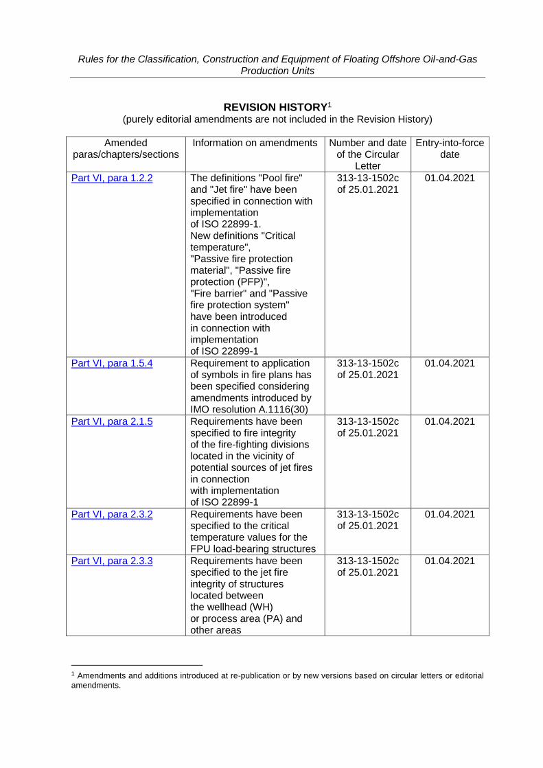
REVISION HISTORY1 (purely editorial amendments are not included in the Revision History)
Amended paras/chapters/sections
Information on amendments Number and date of the Circular
Letter
Entry-into-force date
Part VI, para 1.2.2 The definitions "Pool fire" and "Jet fire" have been specified in connection with implementation of ISO 22899-1. New definitions "Critical temperature", "Passive fire protection material", "Passive fire protection (PFP)", "Fire barrier" and "Passive fire protection system" have been introduced in connection with implementation of ISO 22899-1
313-13-1502c of 25.01.2021
01.04.2021
Part VI, para 1.5.4 Requirement to application of symbols in fire plans has been specified considering amendments introduced by IMO resolution A.1116(30)
313-13-1502c of 25.01.2021
01.04.2021
Part VI, para 2.1.5 Requirements have been specified to fire integrity of the fire-fighting divisions located in the vicinity of potential sources of jet fires in connection with implementation of ISO 22899-1
313-13-1502c of 25.01.2021
01.04.2021
Part VI, para 2.3.2 Requirements have been specified to the critical temperature values for the FPU load-bearing structures
313-13-1502c of 25.01.2021
01.04.2021
Part VI, para 2.3.3 Requirements have been specified to the jet fire integrity of structures located between the wellhead (WH) or process area (PA) and other areas
313-13-1502c of 25.01.2021
01.04.2021
1 Amendments and additions introduced at re-publication or by new versions based on circular letters or editorial
amendments.
Rules for the Classification, Construction and Equipment of Floating Offshore Oil-and-Gas Production Units
Amended paras/chapters/sections
Information on amendments Number and date of the Circular
Letter
Entry-into-force date
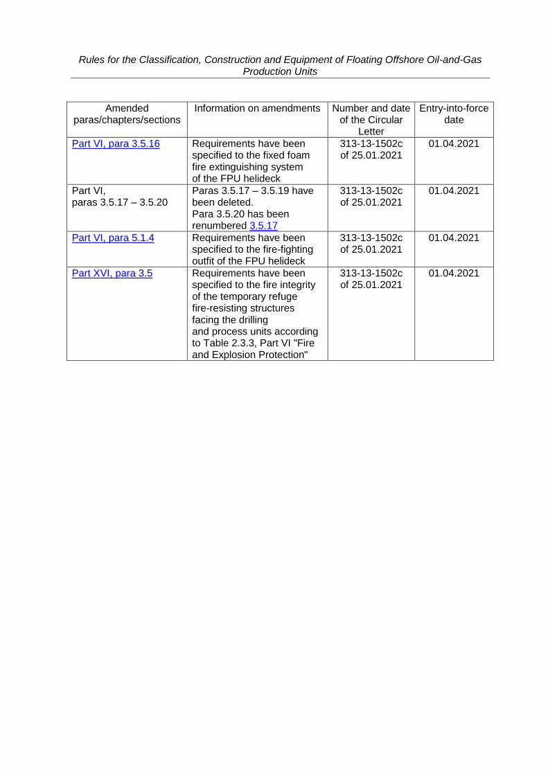
Part VI, para 3.5.16 Requirements have been specified to the fixed foam fire extinguishing system of the FPU helideck
313-13-1502c of 25.01.2021
01.04.2021
Part VI, paras 3.5.17 – 3.5.20
Paras 3.5.17 – 3.5.19 have been deleted. Para 3.5.20 has been renumbered 3.5.17
313-13-1502c of 25.01.2021
01.04.2021
Part VI, para 5.1.4 Requirements have been specified to the fire-fighting outfit of the FPU helideck
313-13-1502c of 25.01.2021
01.04.2021
Part XVI, para 3.5 Requirements have been specified to the fire integrity of the temporary refuge fire-resisting structures facing the drilling and process units according to Table 2.3.3, Part VI "Fire and Explosion Protection"
313-13-1502c of 25.01.2021
01.04.2021
CLASSIFICATION AND CONSTRUCTION OF FLOATING OFFSHORE OIL-AND-GAS
PRODUCTION UNITS (FPU)
Rules for the Classification, Construction and Equipment of Floating Offshore Oil-and-Gas Production Units (Part I)
6
PART I. CLASSIFICATION
1 GENERAL
1.1 APPLICATION
1.1.1 These Rules for the Classification, Construction and Equipment of Floating Offshore Oil-and-Gas Production Units1 cover the following types of self-propelled and non-self-propelled floating offshore structures:
floating production, storage and offloading units depending on the flow chart chosen; single point moorings. Mobile offshore drilling units, fixed offshore platforms and drilling ships shall meet the
requirements of the Rules for the Classification, Construction and Equipment of Mobile Offshore Drilling Units and Fixed Offshore Platforms2 of Russian Maritime Register of Shipping3.
1.1.2 Technical requirements apply to machinery, arrangements, instruments and equipment installed on floating offshore structures, except for structures, machinery, arrangements, instruments and equipment of systems for production, treatment and processing of products, technical requirements to which are set forth in the Rules for the Oil-and-Gas Equipment of Floating Offshore Oil-and-Gas Production Units, Mobile Offshore Drilling Units and Fixed Offshore Platforms.
1.1.3 The equipment, machinery and piping of the floating offshore oil-and-gas production unit (FPU), which ensure its operation as a floating offshore structure, shall meet the requirements of the Rules for the Classification and Construction of Sea-Going Ships4 and the MODU/FOP Rules of the Register to the extent that they are applicable and sufficient, unless otherwise specified.
1.1.4 The materials, products, welding and inspection of welded joints used for hull structures, machinery and equipment parts shall comply with the RS Rules and the MODU/FOP Rules to the extent that they are applicable and sufficient.
1 Hereinafter referred to as "the FPU Rules". 2 Hereinafter referred to as "the MODU/FOP Rules". 3 Hereinafter referred to as "the Register". 4 Hereinafter referred to as "the RS Rules".
Rules for the Classification, Construction and Equipment of Floating Offshore Oil-and-Gas Production Units (Part I)
7
1.2 DEFINITIONS AND EXPLANATIONS
1.2.1 For the purpose of the FPU Rules, the following definitions have been adopted.
A c c o m m o d a t i o n a r e a is the FPU area used for the crew and special personnel accommodation.
B r i d l e is a chain cable connecting a ship or a mooring buoy to an anchor. Combined bridle is a bridle with intermediate chain lengths (between the inner end and anchor chain lengths) replaced with the wire rope ones.
F l o a t i n g o f f s h o r e o i l - a n d - g a s p r o d u c t i o n u n i t ( F P U ) is a floating offshore ship-, pontoon- or otherwise-shaped structure provided with a position-keeping system and intended for performing one or several functions: production, intake, storage, processing and offloading of products.
F l o a t i n g p r o d u c t i o n a n d o f f l o a d i n g u n i t ( F P O ) is a floating offshore structure intended for intake, processing and offloading of products.
F l o a t i n g p r o d u c t i o n , s t o r a g e a n d o f f l o a d i n g u n i t ( F P S O ) is a floating offshore self-propelled or non-self-propelled structure intended for intake, processing, storage and offloading of products.
F l o a t i n g s i n g l e p o i n t m o o r i n g ( F S P M ) is a floating offshore structure intended for mooring tankers or FPU and for offloading of products at sea or at anchorage.
F l o a t i n g s t o r a g e a n d o f f l o a d i n g u n i t ( F S O ) is a floating offshore self-propelled or non-self-propelled structure intended for intake, storage and offloading of products.
M u l t i p h a s e ( m u l t i l e v e l ) s w i v e l is a rotating device, which provides transfer of products, other media (water, gas, etc.), as well as electric power, monitoring and control signals between its rotating and stationary parts.
P r o c e s s a r e a is the FPU area wherein the equipment for intake, processing, storage and offloading of products is installed.
P r o d u c t s are crude hydrocarbons in the form of oil, natural or oil gas and gas condensate.
R i s e r is a structure composed of a rigid or flexible pipeline which connects the equipment of underwater production system or subsea pipeline manifold with FPU or a single point mooring for product transportation.
S t a t i o n a r y s i n g l e p o i n t m o o r i n g ( S S P M ) is an offshore structure installed on the seabed and intended for mooring tankers or FPU and for offloading of products at sea or at anchorage.
T u r r e t is a device providing FPU and FSPM connection and enabling FPU to rotate around FSPM, as well as to transport products and other media via the multiphase swivel.

Rules for the Classification, Construction and Equipment of Floating Offshore Oil-and-Gas Production Units (Part I)
8
2 CLASS OF FPU
2.1 GENERAL
2.1.1 FPU are covered by the requirements of 2.1, Part I "Classification" of the RS Rules.

Rules for the Classification, Construction and Equipment of Floating Offshore Oil-and-Gas Production Units (Part I)
9
2.2 CLASS NOTATION
2.2.1 The class notation assigned by the Register to a floating offshore structure consists of the character of classification, distinguishing marks and descriptive notations defining design and purpose of a floating offshore structure.
2.2.2 Floating structures complying with the requirements of Section 2, Part I "Classification" of the RS Rules are assigned one of the following descriptive notations added to the character of classification, namely: FPO, FPSO, FSO, FSPM or SSPM, depending on the flow chart chosen and subject to compliance with the requirements of the FPU Rules.
For self-propelled ships, when adding descriptive notations to the character of classification such as FSO or FPSO, the sign (ESP) shall be mandatory added after the descriptive notation. This means the necessity to survey these ships based on the Enhanced Survey Programme.
2.2.3 If a ship is intended for periodical operation at fixed location in regasification and gas offloading mode or gas intake, processing, liquefaction and storage mode, when one descriptive notation from those specified in 2.2.2 is assigned, the descriptive notation gas carrier shall be also added to the character of classification. This ship shall meet the requirements of the Rules for the Classification and Construction of Ships Carrying Liquefied Gases in Bulk and the Rules for the Classification and Construction of Ships Carrying Compressed Natural Gas to the extent that is practicable and reasonable.

Rules for the Classification, Construction and Equipment of Floating Offshore Oil-and-Gas Production Units (Part I)
10
3 TECHNICAL DOCUMENTATION
3.1 General provisions pertinent to the review and approval of technical documentation on FPU, materials and products are given in Section 3, Part I "Classification" of the RS Rules and in Section 4, Part I "Classification" of the MODU/FOP Rules.
3.2 The design documentation for ship under construction, technical design documentation, as well as working documentation for FPU under construction shall be submitted to the Register for review and approval in accordance with the requirements of Section 3, Part I "Classification" of the RS Rules and Section 4, Part I "Classification" of the MODU/FOP Rules to the extent that is applicable to FPU.
3.3 Technical documentation reflecting the specific feature of FPU shall be additionally submitted, namely:
area and conditions of operation, anchorage system (in accordance with 4.1.2 to 4.1.12, Part I "Classification" of the MODU/FOP Rules);
drawings and diagrams of an offloading system, hull structures in way of production complexes, of a turret, torch, an integrated automatic control system, a mooring arrangement, helideck equipment.
3.4 Prior to the commencement of work on conversion/modernization of FPU, technical documentation for those parts of the hull, machinery and equipment of FPU, which are liable to conversion/modernization, shall be submitted to the Register for review.
3.5 When fitting new machinery or arrangements on FPU in operation, which meet the requirements of the FPU Rules and differ substantially from those fitted initially, the additional technical documentation concerning the items of new equipment shall be submitted to the Register for review.
3.6 Upon completion of construction, trails and commissioning of FPU, the final documentation shall be submitted to the Register.
The amount of the documentation and the order of its submission shall be agreed upon with the Register prior to completion of the FPU construction.
Rules for the Classification, Construction and Equipment of Floating Offshore Oil-and-Gas Production Units (Part I)
11
4 SURVEY PROCEDURE AND SCOPE
4.1 The following types of surveys are performed by the Register: .1 initial surveys: initial survey during construction under the Register technical supervision, initial survey during construction under the supervision of another classification society
(ACS) or any other competent body, or without the ACS supervision, initial survey in service; .2 periodical surveys in service as follows: special surveys; annual surveys; survey of the outside of the ship's bottom; intermediate surveys; .3 occasional surveys in service. 4.2 Survey of FPU in service shall be carried out in compliance with the
requirements of Section 2 of the General Regulations for the Classification and Other Activity, Section 3, Part I "Classification" of the MODU/FOP Rules, and of the Rules for the Classification Surveys of Ships in Service and the Guidelines on Technical Supervision of Ships in Service to the extent that is practicable and reasonable, unless otherwise specified.
4.3 FPU under construction is subject to surveys in the scope prescribed by the MODU/FOP Rules, Guidelines on Technical Supervision during Construction of Mobile Offshore Drilling Units and Fixed Offshore Platforms and Manufacture of Materials and Products, technical design and working documentation.
4.4 Date of the FPU survey upon construction is the date of the actual completion of the survey and issue of a Classification Certificate and ship's documents for FPU.
Rules for the Classification, Construction and Equipment of Floating Offshore Oil-and-Gas Production Units (Part II)
12
PART II. HULL
1 GENERAL REQUIREMENTS
1.1 The requirements of this Part apply to the floating offshore structures specified in 1.1.1, Part I "Classification".
1.2 Depending on the FPU structural type, the dimensions of hull structural members shall meet the following normative documents:
steel ship- and pontoon-shaped FPU – Part II "Hull" of the RS Rules; steel semi-submersible, self-elevating, gravity (including reinforced and steel concrete),
tension leg and moored FPU – Part II "Hull" of the MODU/FOP Rules. The dimensions of the FPU hull structural members of other structural types shall be
defined according to specifications describing operation conditions, methods for determination of external loads, design operating modes, safety factors and requirements to structural members. When developing the specifications, the requirements of the IMO Code for the Construction and Equipment of MODU (2009 MODU Code) (IMO resolution A.1023(26) with Appendices). ISO standards of 19900 series or API standards.
In case the cargo tanks are planned to be installed on FPU, the FPU structure shall meet the requirements of Part II "Gas Carrier Design" of the Rules for the Classification and Construction of Ships Carrying Liquefied Gases in Bulk and cargo tanks shall meet the requirements of Part IV "Cargo Tanks" of the Rules for the Classification and Construction of Ships Carrying Liquefied Gases in Bulk.
In case the hull of existing oil tanker or gas carrier is planned to be used as the FPU hull, the hull suitability shall be confirmed by the technical condition assessment performed in compliance with the requirements of Appendix 2 of the Rules for Classification Surveys of Ships in Service.
1.3 Materials for production of the FPU structures shall meet the requirements of Part XIII "Materials" of the RS Rules and Part XIII "Materials" of the MODU/FOP Rules.
Rules for the Classification, Construction and Equipment of Floating Offshore Oil-and-Gas Production Units (Part III)
13
PART III. EQUIPMENT, ARRANGEMENTS AND OUTFIT
1 GENERAL
1.1 APPLICATION
1.1.1 FPU are covered by the applicable requirements of Part III "Equipment, Arrangements and Outfit" of the RS Rules and Part III "Equipment, Arrangements and Outfit of MODU/FOP" of the MODU/FOP Rules, unless otherwise specified in this Part.
1.1.2 The requirements of this Part do not apply to the following equipment, arrangements and outfit:
industrial equipment used for drilling or associated operations; equipment for formation of products; equipment for treatment of products; equipment for processing of products.
Rules for the Classification, Construction and Equipment of Floating Offshore Oil-and-Gas Production Units (Part III)
14
1.2 DEFINITIONS AND EXPLANATIONS
1.2.1 Definitions and explanations, except listed below, are given in the General Regulations for the Classification and Other Activity, Part I "Classification" and Part III "Equipment, Arrangements and Outfit" of the RS Rules, Part I "Classification" and Part III "Equipment, Arrangements and Outfit of MODU/FOP" of the MODU/FOP Rules, as well as in Part I "Classification" and Part II "Hull" of the FPU Rules.
L o n g b r i d l e is the bridle that has an anchor-adjacent section, which rests on the seabed within the entire range of design loads.
S h o r t b r i d l e is the bridle that may lift off from the seabed over its entire length under design loads.
Rules for the Classification, Construction and Equipment of Floating Offshore Oil-and-Gas Production Units (Part III)
15
1.3 SCOPE OF TECHNICAL SUPERVISION
1.3.1 General provisions on the technical supervision of equipment, arrangements and outfit are set forth in the General Regulations for the Classification and Other Activity and in Part I "Classification" of the RS Rules, Part I "Classification" and Part III "Equipment, Arrangements and Outfit of MODU/FOP" of the MODU/FOP Rules, as well as in Part I "Classification" of the FPU Rules.
1.3.2 Technical supervision covers the products included into the FPU equipment, arrangements and outfit and stated in the list given in 1.3, Part III "Equipment, Arrangements and Outfit" of the RS Rules to the extent which is reasonable for the particular FPU type.
1.3.3 The items of equipment, arrangements and outfit listed in 1.3, Part III "Equipment, Arrangements and Outfit" of the RS Rules shall be monitored by the Register to meet the requirements of Part XIII "Materials" and Part XIV "Welding" of the RS Rules, as well as Part XIII "Materials" and Part XIV "Welding" of the FPU Rules.
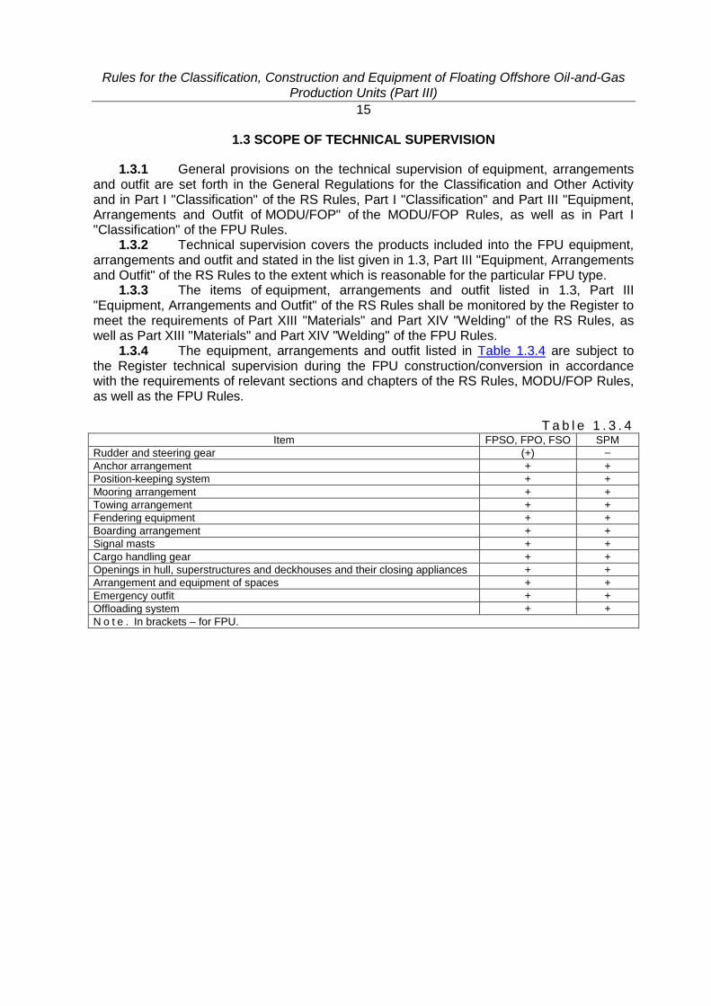
1.3.4 The equipment, arrangements and outfit listed in Table 1.3.4 are subject to the Register technical supervision during the FPU construction/conversion in accordance with the requirements of relevant sections and chapters of the RS Rules, MODU/FOP Rules, as well as the FPU Rules.
T a b l e 1 . 3 . 4 Item FPSO, FPO, FSO SPM
Rudder and steering gear (+) –
Anchor arrangement + +
Position-keeping system + +
Mooring arrangement + +
Towing arrangement + +
Fendering equipment + +
Boarding arrangement + +
Signal masts + +
Cargo handling gear + +
Openings in hull, superstructures and deckhouses and their closing appliances + +
Arrangement and equipment of spaces + +
Emergency outfit + +
Offloading system + +
N o t e . In brackets – for FPU.
Rules for the Classification, Construction and Equipment of Floating Offshore Oil-and-Gas Production Units (Part III)
16
1.4 GENERAL REQUIREMENTS
1.4.1 Installation of machinery directly on the decks, being the top of cargo and fuel oil tanks, shall be performed in compliance with 1.4.1, Part III "Equipment, Arrangements and Outfit" of the RS Rules.

Rules for the Classification, Construction and Equipment of Floating Offshore Oil-and-Gas Production Units (Part III)
17
1.5 MATERIALS AND WELDING
1.5.1 Steel structures shall comply with the requirements of Part II "Hull" and Part XIII "Materials".
1.5.2 Welding of structural elements of equipment, arrangements and outfit shall be performed in compliance with the requirements of Part II "Hull" and Part XIV "Welding".
Rules for the Classification, Construction and Equipment of Floating Offshore Oil-and-Gas Production Units (Part III)
18
1.6 DESIGN ACCELERATIONS DUE TO HEAVE AT SEA
1.6.1 The dimensionless accelerations due to heave at sea shall be applied when determining the load upon arrangements and equipment on the ship- or pontoon-shaped FPU of the unrestricted service and those restricted area of navigation R1 given in 1.7, Part III "Equipment, Arrangements and Outfit" of the RS Rules.
1.6.2 With regard to non-ship-shaped FPU of other areas of navigation, accelerations may be applied different from those required herein which shall be substantiated by calculations approved by the Register.
Rules for the Classification, Construction and Equipment of Floating Offshore Oil-and-Gas Production Units (Part III)
19
2 RUDDER AND STEERING GEAR
2.1 The rudder and steering gear and the active means of the FPU steering shall meet the requirements of Section 2, Part III "Equipment, Arrangements and Outfit" of the RS Rules.
Rules for the Classification, Construction and Equipment of Floating Offshore Oil-and-Gas Production Units (Part III)
20
3 ANCHOR ARRANGEMENT
3.1 GENERAL
3.1.1 The anchor arrangement on self-propelled FPU shall meet the requirements of Section 3, Part III "Equipment, Arrangements and Outfit" of the RS Rules as applied to transport ships.
3.1.2 The anchor arrangement on manned FSPM shall meet the requirements of Section 3, Part III "Equipment, Arrangements and Outfit of MODU/FOP" of the MODU/FOP Rules.
3.1.3 The anchor arrangement on SSPM or unmanned FSPM may be of a temporary nature.
Taking into account the personnel, machinery and power source, the temporary anchor arrangement shall provide:
FPU anchorage during its fitting-out afloat (loading of solid ballast, systems testing); FPU position-keeping (additionally to the tug service) while holding anchorage in transit
under conditions which severity is in excess of the permissible ones; FPU positioning and position-keeping during installation on the seabed. 3.1.4 Chain lockers and chain pipes shall be located outside the hazardous area. If
such arrangement is impracticable, these structures shall be protected from gas penetration.
Rules for the Classification, Construction and Equipment of Floating Offshore Oil-and-Gas Production Units (Part III)
21
3.2 TEMPORARY ANCHOR ARRANGEMENT
3.2.1 General requirements. 3.2.1.1 The anchor arrangement may be fitted not only on the FPU hull, but on the
temporary overhang (exposed) platforms, and the individual items of the anchor arrangement (hawse pipes, chocks, connecting shackles, etc.) may be located to be used for other arrangements (towing, mooring, etc.) taking into account the possibility of their further application in the FPU transit to the new operational area or for utilization.
3.2.1.2 The development and use of temporary anchor arrangement are allowed, provided the following is submitted:
data on the seabed, seismic activity and prevailing hydrometeorological conditions in the specific area;
necessary data and calculations defining the operation conditions of all the anchor arrangement elements;
arrangement plans indicating temporary anchor arrangement location including anchors, anchor lines comprising chains, wire, synthetic fibre ropes or their combination, machinery and any other elements;
design calculation of anchor arrangements during the performance of particular operations.
3.2.2 Calculation principles for temporary anchor arrangement. 3.2.2.1 The FPU anchor equipment shall be determined by special calculations based
on the environmental conditions and corresponding loads during performance of specific operations, having regard for the FPU additional position-keeping and positioning provided by auxiliary tow order vessels.
The anchor equipment may be selected according to 3.1.5 and 3.1.6, Part III "Equipment, Arrangements and Outfit of MODU/FOP" of the MODU/FOP Rules by the equipment number Ne determined by the formula
𝑁𝑒 = 𝐾1𝐾2∆2/3 + 𝐾3𝐴, (3.2.2.1) where 𝐾1 , 𝐾2, 𝐾3 = coefficients accounting for the hull shape, wave effect and wind conditions at the
anchorage, respectively; Δ = displacement volume of FPU during operation, in m3; A = total windage projected area of the structures above the waterline on the plane
normal to the horizontal projection of an anchor line, in m2.
The coefficient К1 is recommended to obtain from the ratio R/R', where R' and R are
resistances of the submerged part of a conventional ship and FPU with the same displacements and towing speed, respectively.
The coefficients К2 and К3 shall be taken in compliance with Table 3.2.2, Part III "Equipment, Arrangements and Outfit of MODU/FOP" of the MODU/FOP Rules.
The Register may accept other values of coefficients, provided it is proved that the proposed values are in agreement with the actual construction, service and repair conditions.
3.2.2.2 The anchor arrangement elements shall be designed taking into account 4.3.3, Part III "Equipment, Arrangements and Outfit of MODU/FOP" of the MODU/FOP Rules.
3.2.2.3 Safety factors for each particular element of the anchor arrangement are recommended to obtain similarly to anchor arrangements in accordance with 3.1.5 and 3.3.4, Part III "Equipment, Arrangements and Outfit of MODU/FOP" of the MODU/FOP Rules.
Rules for the Classification, Construction and Equipment of Floating Offshore Oil-and-Gas Production Units (Part III)
22
The rated forces for the particular elements of the anchor arrangement are determined based on the breaking load value for anchor lines meeting the requirements of 3.6, Part III "Equipment, Arrangements and Outfit" and 6.3, Part IX "Machinery" of the RS Rules.
3.2.3 Temporary anchor arrangement structure. 3.2.3.1 FPU is recommended to be provided with at least two anchors. Temporary anchor arrangement shall generally include: bower anchors; anchor lines; devices for securing and releasing the inboard end of the chain cable (senhouse slips, etc.); machinery for dropping and hoisting bower anchors and the FPU positioning with the
dropped anchors (where the anchor arrangement is used for the FPU positioning); stoppers ensuring the FPU riding at anchors; chain lockers or platforms for storage of anchor ropes and chain cables, and other
special equipment necessary for a specific marine operation. The number of separate anchor arrangement elements is determined by calculations. 3.2.3.2 The following types of anchors may be used as bower anchors: Hall's or
Gruson's and admiralty stocked anchors. 3.2.3.3 Chains of various strength grades are recommended to be used as anchor
lines. If justified with due regard to the short-term nature of operations, the chains may be replaced with wire and synthetic fibre ropes of adequate strength.
3.2.3.4 The anchor lines characteristics shall be determined on the basis of special calculations on the assumption that they will ensure the required holding power and anchor loading under specific conditions at the design environmental effects. Anchor lines and their complete set shall meet the requirements of Section 7, Part XIII "Materials" of the RS Rules. Where combination anchor lines are used, which include chain and rope inserts, the complete set shall ensure the continuous rope tension (due to the weight of chain sections) to preclude formation of sheepshank knots on the rope inserts.
3.2.3.5 Each bower-anchor chain cable and rope shall be provided with a stopper intended for the FPU riding at anchor. Where the length of the anchor lines is fixed and there is no need for position mooring the stopper may be replaced with the device for securing and releasing the inboard end of the chain cable.
The stoppers shall be supplemented with the devices for securing and releasing the inboard ends of the anchor chain cables and ropes where the FPU position mooring is necessary for its installation.
3.2.3.6 Laying of anchor lines shall provide for their free run when dropping or hoisting the anchors in compliance with the requirements of 3.6.3, Part III "Equipment, Arrangements and Outfit" of the RS Rules.
Chain lockers shall meet the requirements of 3.6.4, Part III "Equipment, Arrangements and Outfit" of the RS Rules.
The platforms for stowing chain cables or ropes shall be dimensioned and located so that they ensure the free stowage of the specified length of anchor chain cables using the FPU cargo handling gear, the free lead of chain cables through the chain pipes and their free veering away when dropping the anchors.
3.2.3.7 If fitted with the proper equipment, the carriage, dropping and hoisting the anchors and anchor chain cables or ropes may be provided by the auxiliary tow order vessels.
3.2.3.8 Anchor machinery shall be fitted for dropping and hoisting the bower anchors, and also for position mooring during the FPU installation. If there is no need for the FPU position mooring, as well as where the carriage, dropping and hoisting of anchors are provided by the auxiliary tow order vessels, FPU may be not equipped with anchor machinery.
Rules for the Classification, Construction and Equipment of Floating Offshore Oil-and-Gas Production Units (Part III)
23
The power of anchor machinery shall be determined based on the actual mass and overall characteristics of anchor equipment, the requirements for the FPU positioning, the conditions during operations performance etc.
Where FPU is provided with the anchor machinery, or the winches available on FPU are used for anchor and chain cable handling operations, these machinery shall meet the requirements of the RS Rules and MODU/FOP Rules. Where the auxiliary tow order vessels machinery is used for anchor handling operations, it shall be verified for compliance with the MODU/FOP Rules considering the characteristics of the FPU anchor arrangement. Anchor machinery shall be designed to meet the requirements of 6.3, Part IX "Machinery" of the RS Rules.
3.2.3.9 A spare set of anchor equipment (anchor, anchor line and joining devices) is recommended to be provided on board FPU for the prolonged (more than a week) towings at sea.
Rules for the Classification, Construction and Equipment of Floating Offshore Oil-and-Gas Production Units (Part III)
24
4 POSITION-KEEPING SYSTEMS
4.1 GENERAL
4.1.1 The requirements of this Section apply to the systems intended for position-keeping of FPU at a certain location with restriction of shiftings within the prescribed limits and ensuring normal conditions to perform technological processes at a site.
4.1.2 The requirements cover the following: .1 anchoring systems which include anchors and flexible anchor lines; .2 anchoring systems which include anchors and tension anchor lines; .3 dynamic positioning systems; .4 thruster assisted position mooring systems. 4.1.3 The position-keeping system including winches and chain stoppers shall be
located on the open deck within non-hazardous areas, unless special measures are provided to avoid risk of ignition during normal operations and accidental disconnection.
Rules for the Classification, Construction and Equipment of Floating Offshore Oil-and-Gas Production Units (Part III)
25
4.2 POSITION MOORING SYSTEM
4.2.1 The FPU position mooring system shall provide their position-keeping: under operation conditions at the design external loads and with a tied up transport ship
(TS) (including condition with one anchor line broken at reduced safety factors meeting the requirements of 4.3.10 and 4.3.11, Part III "Equipment, Arrangements and Outfit" of the MODU/FOP Rules);
under extreme conditions without a tied up transport ship and at the stormy weather potential once in 100 years (including condition with one anchor line broken at reduced safety factors).
4.2.2 Position mooring system shall ensure the limitation of the FPU horizontal movements at design conditions.
4.2.3 The laying out of anchor lines for the FPU position-keeping shall not result in the limitations on the TS maneuvering and draught.
4.2.4 Position mooring system are divided by the way of position-keeping into two types: type I: positioned with the anchor lines which ensure position-keeping above the
specified seabed location being exposed to horizontal loads; type II: positioned with the tension anchor lines which ensure both the position-keeping
above the specified seabed location and the minimum changes of the distance from the structure bottom to the seabed being exposed to horizontal and vertical loads at the maximum depression (lowering) of sea level (due to waves, ebb-tide, natural level depression).
4.2.5 Multi-anchor (distributed) and single-anchor type I systems are recommended for position-keeping of the FPU in question.
4.2.6 Position mooring system shall be designed in compliance with Section 4, Part III "Equipment, Arrangements and Outfit of MODU/FOP" of the MODU/FOP Rules.
4.2.7 Position mooring system parameters are recommended to be determined using the step-by-step approach as follows:
determine the laying out, mass and number of anchors (anchor lines), the length, diameter and strength grade of bridles with the use of analogues taking into account the level of external loads due to natural factors and the distribution of sea depths at the position mooring system location;
determine the mass of anchors and the forces of anchor lines pretension; calculate the maximum forces in bridles exposed to external loads due to the natural
factors potential once in 100 years; determine safety factors and compare them with the standard ones; make the corrections of position mooring system parameters according to the
comparison results and repeat the calculation if needed; calculations shall be continued until the satisfactory precision of values of acting and
permissible forces is reached. 4.2.8 When performing calculations for position mooring system, the software
having Type Approval Certificate issued by the Register shall be used. 4.2.9 The documentation meeting the requirements of 4.2.2 and 4.2.3, Part III
"Equipment, Arrangements and Outfit of MODU/FOP" of the MODU/FOP Rules shall be submitted to the Register.
4.2.10 System design shall meet the requirements of 4.3, Part III "Equipment, Arrangements and Outfit of MODU/FOP" of the MODU/FOP Rules.
4.2.11 System equipment (winches, tensioning devices, fairleads and guiding devices) and system control stations shall meet the requirements of 4.4 and 4.8, Part III "Equipment, Arrangements and Outfit of MODU/FOP" of the MODU/FOP Rules, respectively.
Rules for the Classification, Construction and Equipment of Floating Offshore Oil-and-Gas Production Units (Part III)
26
4.3 ANCHORS
4.3.1 Depending on the seabed, pile, plate, suction, gravity, shot-driven and explosive-driven anchors, as well as ship anchors may be used for the FPU position-keeping.
4.3.1.1 Pile anchors are capable to withstand vertical and horizontal loads and are installed (embedded) using hammers, drilling and washout with a water jet under pressure.
4.3.1.2 Plate anchors are manufactured by welding of plate components, and they have high holding power in clay and silt seabed.
4.3.1.3 Suction anchors are caissons used in soft and medium hard soils, and are embedded by pumping out water from the caisson.
4.3.1.4 Gravity anchors are reinforced concrete/steel and concrete structures which holding power is equal to its weight in water along all directions.
4.3.1.5 Explosive-driven anchors are used in shallow water, and embedded into the seabed by a shot or a series of explosions and turned around by the anchor line tension towards the position corresponding to the maximum resistance to loading.
4.3.1.6 Ship anchors embedded during dragging are used for the grounds other than the hard ones.
4.3.2 Anchors are subdivided subject to the following: direction of operation (all-around and directional); operating principle (gravity, pile and circular); material (steel and reinforced concrete); design (solid, combined, pontoons, frames and composite). Gravity anchors are subdivided subject to the following: shape of cross-section (pyramid-shaped, segment, mushroom-shaped, plate-type and a
"frog" with one or two knives); mass: small (< 50 t), medium (> 50 t, but < 100 t), large (> 100 t, but < 300 t) and very
large (> 300 t, but < 900 t). 4.3.3 Characteristics of anchors shall be selected subject to the load applied, soil
properties, safety factors for shear (1,05 – 1,3) and capsizing (1,1 – 1,4). In this case, anchor displacements while in operation shall be prevented and the requirements for the accuracy of anchor installation (normally 5 % of the sea depth unless the additional requirements for the installation accuracy are specified) shall be considered.
When selecting the anchor type, the characteristics of the facilities, which may be used during the anchor transportation and installation, shall also be considered.
4.3.4 The anchor mass shall be defined by the holding power value with due regard to a safety factor, which is assumed according to normative documents, and depends on the anchor type and shape, soil characteristics and effective loads.
4.3.5 Anchor holding power shall ensure its resistance to displacements and rotations exposed to external forces due to its design and the scheme of transmitting bridle-to-anchor forces.
4.3.6 The load transmitted to an anchor is defined by the value of a rated force on the bridle at the seabed level and the angle of its approach to the seabed surface which shall be determined by calculating the FPU position-keeping system.
Rules for the Classification, Construction and Equipment of Floating Offshore Oil-and-Gas Production Units (Part III)
27
4.4 BRIDLES
4.4.1 Bridles intended for transmitting load to an anchor may consist of a chain cable, a wire rope, synthetic ropes or combinations thereof. Chain bridles, sometimes with the wire rope inserts, are generally used for position-keeping of large FPU.
4.4.2 For chain bridles the chain cables of categories 1, 2, 3, as well as R3, R3S, R4, R4S and R5 according to Section 7, Part XIII "Materials" of the RS Rules may be used.
4.4.3 Bridle diameter is determined considering the maximum design load on FPU. 4.4.4 Long and short bridles may be used in the position mooring system. 4.4.5 For gravity reinforced concrete anchors, angle between the bridle and the
horizontal plane at the point of its securing to the anchor α ≤ 15 – 20°. In this case, the vertical component of the force transmitted to the anchor and the corresponding reduction of its holding power shall be considered.
4.4.6 Suspended weight may be used for reducing the angle α and for increasing the damping properties of the bridle.
4.4.7 The bridle rigidity is defined as the ratio of the horizontal force increment to the initiated displacement of its top end. The rigidity depends on the location depth, bridle length, initial tension of the bridle and its linear weight.
Rules for the Classification, Construction and Equipment of Floating Offshore Oil-and-Gas Production Units (Part III)
28
4.5 DESIGN LOADS
4.5.1 Design external loads for the position mooring system design shall be determined in accordance with Section 3, Part II "Hull".
4.5.2 The FPU response to external effects may be conventionally divided into four frequency ranges:
quasi-static or a zero frequency range determined by the sea level, averaged wind and current;
slowly varying (low-frequency) range induced by gust wind and second order wave loads (drift loads), and by current;
medium-frequency range determined by first order wave loads and diffraction; high-frequency range (including heave, pitch and roll resonances) associated with
higher order wave effects and resulted in the longitudinal and transverse vibrations of lines. The first two may be conventionally considered as the static ones, while the rest two as
the dynamic ones. When using the static approach, it is assumed that the line tension depends on the co-ordinates of the line ends only, while the dynamic one additionally considers the speed and accelerations thereof.
4.5.3 The following parameters are critical for FPU: maximum and minimum tensions of lines; the FPU horizontal, vertical and angular displacements and its accelerations due to
wind, current and wave; displacements of the FPU movable joint of the main pipeline; parameters affecting fatigue strength of the lines (moments of zero-, second- and fourth-
order displacement spectra). 4.5.4 For prolonged holding of the bend and rotation angle of the bottom flexible
assembly of the rigid pipe within 1 – 2°, it is recommended to ensure at first approximation the horizontal mean displacement (statics + drift) equal to 2 – 4 % of the sea depth under the FPU bottom (the lesser figure refers to depths of 600 – 1000 m, the greater one, to depths under 100 m; the values for depths of 100 – 600 m are obtained by linear interpolation).
It is recommended to ensure at first approximation the maximum horizontal displacement (dynamics) under the bottom equal to 8 – 12 % of the sea depth with the same depth ratios in order to be within the limits for the angles of deformations of pipe slip joints due to surging, swaying and heaving motions, and also in order to ensure the angular oscillation amplitudes for flexible ground joint within 4,5 – 6°.
Where a flexible pipe is available, the permissible horizontal displacements are as follows (per cent of the depth under the bottom with the same depth ratios):
mean: 3 – 5 and 5 – 10; maximum: 10 – 15 and 15 – 30. 4.5.5 In addition to the factors and external loads specified in Part II "Hull", the
temperature of water and air, fouling, as well as all types of the FPU motions, and FSPM-FPU motions (heave, roll, pitch, sway, surge, yaw) shall be considered.
4.5.6 Various loading conditions of FPU (different amount of product and liquid ballast) shall be additionally considered for FSPM-FPU, and limiting mooring and offloading conditions, i.e. TS position-keeping conditions shall be calculated.
4.5.7 Considering the position mooring system particular response to resonance oscillations on the environmental effect frequencies, special attention shall be paid to the evaluation of the resonance oscillations in determining design loads, in particular:
sway and yaw motions of the moored TS; surge motions of TS; pitch motions of the hull, and FSPM-FPU which may cause the formation of "snakes" in
slack chains;
Rules for the Classification, Construction and Equipment of Floating Offshore Oil-and-Gas Production Units (Part III)
29
heave motions of FSPM with the moored TS (or without it) which causes the change of the anchor line tension;
yaw of FSPM with the moored TS (or without it) including instantaneous loads on a tension anchor line.
In addition, the secondary factors which may initiate the resonance shall be considered: head sea impact in calculating wave loads within a coastal strip in an splash zone
(FSPM is fully in the splash zone); change of the water particle velocities direction at the joint action of current and waves; dynamic effects due to the vortex shedding at high current velocities. 4.5.8 Due to the complicated development of theoretical methods for such
calculations, it is recommended to determine the motions and loading by model tests together with design methods. In doing so, the following shall be considered:
reduced effect of field dampening compared to the model test; effect of fouling on wave resistance and inertia forces; effect of resonance on anchor lines sagging. 4.5.9 Position mooring system shall be designed so that the sudden failure of any
anchor line will not cause progressive failure of the remaining anchor lines and position-keeping system as a whole.
4.5.10 The position mooring system elements shall be designed with due regard to the corresponding safety factors using the procedures which allow to identify extreme loading conditions for each element.
Safety factors shall be obtained in compliance with the modes and conditions specified in 1.2.2 and 1.2.3, Part IV "Stability" of the MODU/FOP Rules.
Safety factors given in Tables 4.3.10 and 4.3.11, Part III "Equipment, Arrangements and Outfit of MODU/FOP" of the MODU/FOP Rules, which may be reduced considering the operational conditions, FPU purpose and anchor line type, may be used as a first approximation.
Safety factors for bridles shall be taken in reference to the rated static breaking strength. Safety factors for anchors shall be taken in reference to their holding power.
4.5.11 The maximum tension Tmax at the safety factor SF value shall be determined by the formula
𝑆𝐹 = РВ/𝑇𝑚𝑎𝑥 (4.5.11-1) where РВ = minimum rated breaking strength of the anchor line.
The FPU maximum movements shall meet the condition
𝑥𝑢𝑙𝑡/𝑥 ≥ 𝑘 (4.5.11-2) where 𝑥𝑢𝑙𝑡 = ultimate values of the FPU movements established by the requirements for design and by
the equipment operating manuals; 𝑥 = maximum rated movements for the rated operating mode under consideration;
𝑘 = safety factor the value of which may be taken equal to 1,15 when the quasi-static method is used, and equal to 1,05 when the dynamic method is used.
4.5.12 The fatigue endurance level of anchor lines, determined by the calculation,
shall not be less than thrice the rated service life of the position mooring system. 4.5.13 The total forces due to wind, current and wave shall be calculated at various
angles between them and taking into account the dynamic effect of waves. The angular displacements of the hull and the horizontal displacements of FPU and TS in motions, as well as the deviations of the horizontal force acting on the bridle shall be calculated
Rules for the Classification, Construction and Equipment of Floating Offshore Oil-and-Gas Production Units (Part III)
30
according to the procedure and the program recognized and certified by the Register, respectively.
4.5.14 In addition to the above loads, the initial tension of anchor lines shall be considered.
4.5.15 The diameter of an anchor chain cable, which safety factor is assumed at least 1,5, shall be selected taking into account the effect of the maximum total loads due to initial tension, wind, wave and current on the bridle.
4.5.16 Strength for the position mooring system securing elements (chain locker pipes and chain stoppers) on FPU shall exceed the strength of the weakest link of an anchor line by 30 %.
4.5.17 The calculation of the unit high-frequency oscillations shall take into account the position mooring system rigidity at depths below 70 m and the dynamic calculation of the position mooring system behaviour shall be carried out at depths exceeding 450 m. In particular cases, such a calculation may be required for the lesser water depths as well.
The position mooring system rigidity characteristic shall be determined according to the procedure approved by the Register, and computer program shall be approved by the Register.

Rules for the Classification, Construction and Equipment of Floating Offshore Oil-and-Gas Production Units (Part III)
31
4.6 DYNAMIC POSITIONING SYSTEM
4.6.1 The dynamic positioning system shall meet the requirements of 4.9, Part III "Equipment, Arrangements and Outfit of MODU/FOP" of the MODU/FOP Rules.
Rules for the Classification, Construction and Equipment of Floating Offshore Oil-and-Gas Production Units (Part III)
32
4.7 MOORING SWIVEL
4.7.1 The mooring swivel shall provide the FPU free rotation about the vertical axis and monitor the movement of the tied up TS.
4.7.2 The mooring swivel structure shall withstand the following loads: mooring line; its own weight; dynamic loads due to the FPU motions, wind and current. 4.7.3 The bearings of the mooring swivel/turret shall have sufficient rigidity to
prevent impermissible displacements. 4.7.4 When designing bearings the following factors shall be taken into
consideration: plastic deformation of rolling components and raceways (bearing capacity); fatigue in critical local sections of the outer and inner races; bolts fatigue; carrying capacity of the bearings on the whole, determined by the bearing capacity
of the bolts and cross sections of the races, taking into account the rigidity of structures supporting the races (fixed and rotating).
4.7.5 Carrying capacity of the bearing shall be determined taking into account the balance of forces acting on the rolling elements and the following loads on the race components:
forces caused by securing bolts including possible shear forces; possible pressure at connection point of the component in question with the structure
supporting the race; forces in the cross section of the race (i.e. on end surfaces of the component in
question). 4.7.6 The safety factor for the bearing races shall be not less than: 1,7 by the maximum bearing capacity of the race and bolts; 1,5 by the fatigue strength (90 % probability) at the load factor of 0,7. 4.7.7 The bolt tightness force shall be 65 – 80 % of their yield strength. 4.7.8 For bolts subject to strong tension account shall be taken of cracking due to
stress-actuated corrosion. 4.7.9 Pressure bolts shall be as far as possible equally spaced over a circle.
Rules for the Classification, Construction and Equipment of Floating Offshore Oil-and-Gas Production Units (Part III)
33
4.8 TURRET
4.8.1 The turret shall provide the FPU free rotation about the vertical axis, securing of a number of anchor lines and reliable connection of the fixed and moving parts of cargo pipeline (refer to 4.7.1).
4.8.2 In addition to the loads mentioned in 4.7.5, account shall be taken of the forces caused by the most adverse operating conditions of the anchor lines. Particular emphasis shall be placed on design tolerances and stresses during transfer of critical load.
The support of leading blocks shall be designed for a load equal to minimum strength in case of anchor line being broken. The nominal equivalent stress in the support structure shall not exceed 0,8 the yield strength of the material.
Strength calculations and finite element analysis (FEA) made for unfavourable load acting on the anchor lines shall be submitted.
4.8.3 The turret essential machinery shall be considered as main one. Components and systems shall be chosen with a margin so that failure of a single component cannot result in loss of operability of the turret.
The turret machinery in case of the blackout accident shall be supplied from the emergency source of power within 18 h.
Emergency shutdown system shall be activated automatically when a fire is detected and the maximum permissible concentration of hydrocarbon gas is up to 50 % of the permissible level in way of the turret.
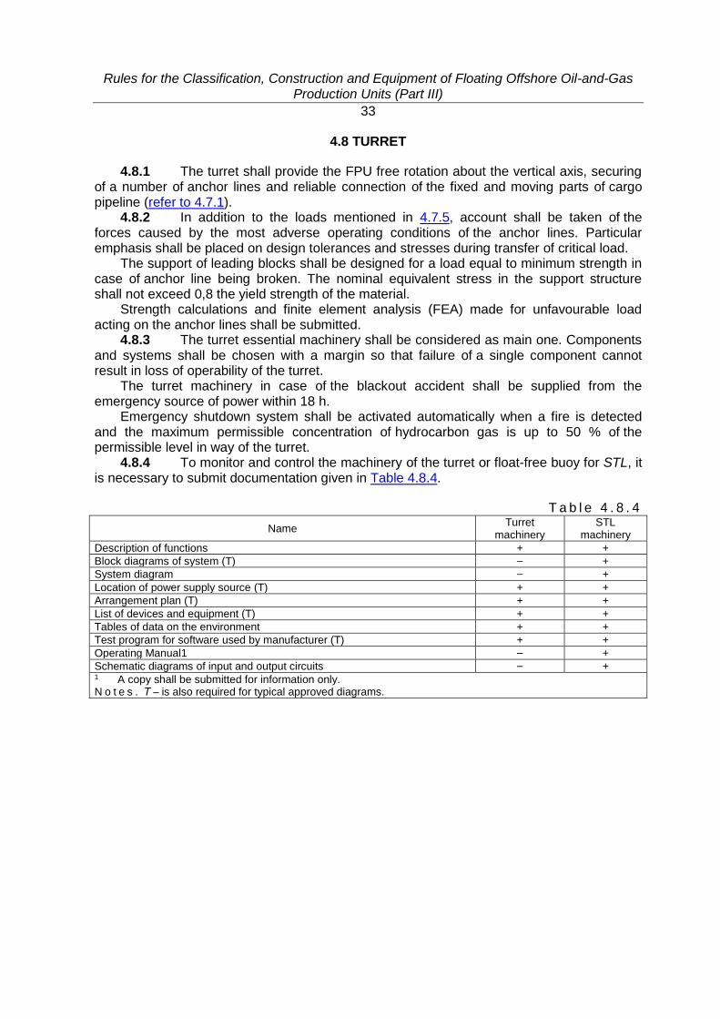
4.8.4 To monitor and control the machinery of the turret or float-free buoy for STL, it is necessary to submit documentation given in Table 4.8.4.
T a b l e 4 . 8 . 4
Name Turret
machinery STL
machinery
Description of functions + +
Block diagrams of system (T) – +
System diagram – +
Location of power supply source (T) + +
Arrangement plan (T) + +
List of devices and equipment (T) + +
Tables of data on the environment + +
Test program for software used by manufacturer (T) + +
Operating Manual1 – +
Schematic diagrams of input and output circuits – + 1 A copy shall be submitted for information only. N o t e s . Т – is also required for typical approved diagrams.
Rules for the Classification, Construction and Equipment of Floating Offshore Oil-and-Gas Production Units (Part III)
34
5 MOORING ARRANGEMENT
5.1 GENERAL
5.1.1 The mooring arrangement on self-propelled FPU shall meet the requirements of Section 4, Part III "Equipment, Arrangements and Outfit" of the RS Rules.
5.1.2 TS mooring shall be as follows: stern mooring with flexible mooring lines; side mooring with flexible mooring lines. 5.1.3 Each FPU shall be provided with the mooring arrangement which ensures TS
warping and its maintaining at a certain distance. 5.1.4 In determining the mooring arrangement characteristics it is recommended to
consider the following conditions: complex solution of the problems associated with mooring and cargo handling
operations (approach, TS position-keeping near FPU, limits for movements during cargo handling operations);
monitoring of mooring and cargo handling operations taking into account the dynamic effects of external forces;
simplicity, workability and repairability of the structure, availability of a "weak link"; dimensions and position of the mooring arrangement shall provide transmission of the
loads carried to the FPU hull structure; relative position of the mooring arrangement components shall contribute to the safer
system "FPU-TS", including the attending personnel injury risk reduction. 5.1.5 The type and location of the mooring arrangement, the loads applied shall be
determined, considering the TS characteristics, environmental loads, operational restrictions, structural features of FPU and vessels involved.
5.1.6 The mooring arrangement shall ensure position-keeping of a tied up ship exposed to the following:
wind; current; tides; waves; ice; draught changes; negative and positive water setup. 5.1.7 The forces caused by draught changes, tidal oscillations, and during cargo
handling operations shall be balanced by the proper handling of mooring lines, in particular, by the installation of appropriate winches.
5.1.8 The wave and ice effect is recommended to assume according to the results of model tests, in-situ measurements or computer-based calculations.

Rules for the Classification, Construction and Equipment of Floating Offshore Oil-and-Gas Production Units (Part III)
35
5.2 INITIAL CALCULATION BACKGROUND
5.2.1 The strength calculations of the mooring arrangement and its supporting hull structures shall be performed according to the procedure agreed with the Register.
Rules for the Classification, Construction and Equipment of Floating Offshore Oil-and-Gas Production Units (Part III)
36
6 TOWING ARRANGEMENT
6.1 The towing arrangement on self-propelled FPU shall meet the requirements of Section 5, Part III "Equipment, Arrangements and Outfit" of the RS Rules.
6.2 FPU shall be provided with the emergency towing arrangement in compliance with 5.7, Part III "Equipment, Arrangements and Outfit" of the RS Rules.
Rules for the Classification, Construction and Equipment of Floating Offshore Oil-and-Gas Production Units (Part III)
37
7 FENDERING EQUIPMENT
7.1 The fendering equipment shall withstand glancing blow of TS in the fully loaded condition or in ballast and ensure the absence of sparking on impact.
7.2 The dimensions and arrangement of the fendering equipment shall be selected so that to ensure protection against the TS of various types considering the rise of tide.
7.3 Where auxiliary vessels are supposed to mooring at FPU, provision shall be made for fenders to protect the FPU hull against damages.
7.4 The characteristics, design and arrangement of the fendering equipment and fenders shall meet the requirements of 4.1.3.2, Part XV "MODU and FOP Safety Assessment" of the MODU/FOP Rules.
7.5 It is recommended to use the structures of high power-capacity rubber shock-absorbers of various types, e.g. axially-compressed cylindrical or specially sectioned (V-shaped, M-shaped).
7.6 The attachment points of the fendering equipment shall include safety device ("weak link") to prevent damage to this equipment due to accidental overloading.
7.7 The fendering equipment strength shall be determined in compliance with the provisions of 5.2.
7.8 The fendering equipment parameters shall be taken considering the following: power-capacity, reaction force and deformation of the fendering equipment taking into
account the impact energy determined according to 3.17.1, Part II "Hull"; necessity of individual design for specific conditions; use of slowly-restorable structures which have high power-capacity at a small reaction
force and low pressure on the side of the ship being moored, as well as a capability of dissipating the ship impact energy with transmitting the loads to the unit hull structures;
low friction coefficient and stability to shear loads; simplicity, workability and repairability; installation of a system to monitor the ship mooring and the means to prevent damage to
the ship hull due to accidental overloading.
Rules for the Classification, Construction and Equipment of Floating Offshore Oil-and-Gas Production Units (Part III)
38
8 BOARDING ARRANGEMENT
8.1 Each FPU shall be provided with a boarding arrangement ensuring access to FPU and its abandonment at any time with due regard to the relevant restrictions (wave height, wind velocity, etc.).
8.2 For FPU methods and equipment shall be additionally developed for emergency evacuation in accident situations.
8.3 Two ways of carrying/evacuating the personnel shall be considered: by ships and helicopters.
8.4 A cargo crane provided with a man-riding cage is recommended as a general means for access to FPU elevated above the water surface, and a verical ladder for access to low FSPM.
8.5 The transfer of people shall be assured at least under the following conditions: wind velocity: 8 to 12,5 m/s; wave height with 3 % probability h3%: 0,75 to 1,25 (force 3); current speed: up to 1 knot. 8.6 The boarding arrangement shall be located on both FPU sides. 8.7 The boarding arrangement shall provide the safe approach of ships with
displacement below 2500 t at a speed of up to 1 knot, and withstand the appropriate loads produced by ships swinging foul without damage to their separate elements and the whole structure.
8.8 The action of ice on the boarding arrangement being inoperable shall be precluded.

Rules for the Classification, Construction and Equipment of Floating Offshore Oil-and-Gas Production Units (Part III)
39
9 SIGNAL MASTS
9.1 Signal masts intended for carrying signal means and aerials shall be designed to meet the requirements of Section 6, Part III "Equipment, Arrangements and Outfit" of the RS Rules.

Rules for the Classification, Construction and Equipment of Floating Offshore Oil-and-Gas Production Units (Part III)
40
10 CARGO HANDLING GEAR
10.1 Cargo handling gear of FPU shall comply with the Rules for the Cargo Handling Gear of Sea-Going Ships.
Rules for the Classification, Construction and Equipment of Floating Offshore Oil-and-Gas Production Units (Part III)
41
11 OPENINGS IN HULL, SUPERSTRUCTURES, DECKHOUSES AND THEIR CLOSING APPLIANCES
11.1 The requirements apply to the arrangement and closing appliances
of openings located above the FPU margin line. The margin line means the line of the intersection of the upper surface of the bulkhead deck (or its continuation) with the outer surface of side shell plating at side.
11.2 Openings in hull, superstructures and deckhouses of FPU, to which a the minimum freeboard has been assigned, and their closing appliances shall meet the Register requirements specified for ships of unrestricted service given in Section 7, Part III "Equipment, Arrangements and Outfit" of the RS Rules and in Section 8, Part III "Equipment, Arrangements and Outfit" of the MODU/FOP Rules to the extent that is reasonable and practicable for FPU in question.
11.3 The coaming height of openings for doors, companion hatches, skylights, ventilation trunks and ventilators, as well as closing appliances of these openings shall be determined with regard to the requirements for the FPU intact and damage stability.
Сovers of companion hatches shall be watertight and fitted with quick acting devices for securing and opening, and also with position indicators.
11.4 Tight manholes having clear dimensions of at least 500 × 600 mm shall be fitted for access to tanks and cofferdams.
11.5 Side scuttles in mooring and cargo control room shall have electric heating and screen wipers. In addition, the control station shall be provided with a washing system for glasses and with light filters.
11.6 Openings in the FPU watertight subdivision bulkheads and their closing appliances shall meet the requirements of 7.12, Part III "Equipment, Arrangements and Outfit" of the RS Rules.
Doors in those bulkheads shall be remotely operated from the central control station on the deck, which is above the damage waterline after flooding.
Water-and-gastight doors made of steel shall be fitted in superstructures, the doors meeting the requirements of 2.1.3.1, Part VI "Fire Protection" of the RS Rules shall be fitted in inner spaces.
The detachable panels of doors used as an emergency exit shall be dimensioned at least 400×500 mm.
Rules for the Classification, Construction and Equipment of Floating Offshore Oil-and-Gas Production Units (Part III)
42
12 ARRANGEMENT AND EQUIPMENT OF SPACES
12.1 The arrangement and equipment of spaces shall meet the requirements of Section 8, Part III "Equipment, Arrangements and Outfit" of the RS Rules for cargo ships.
12.2 Stairways shall be at least 600 mm wide (between stringers), their angle of inclination shall not exceed 55° (60° in cargo tanks), and in extraordinary cases, it may be equal to 65°. The width of vertical ladders shall not be less than 300 mm and of spar ladders, not less than 250 mm.
12.3 The means of access to cargo tanks shall meet the requirements of 7.14.2, Part III "Equipment, Arrangements and Outfit" of the RS Rules.
12.4 Guard rails of open decks and working stations shall be four-rowed and of 1100 mm high, and in inner spaces, three-rowed and of 1000 mm high.
12.5 Deck machinery and devices shall be provided with covers. 12.6 Spare parts and appliances shall be taken according to the supplier's
recommendations given in specifications for the supply of machinery, apparatus and other equipment, and for arrangements and systems, according to the requirements of the Register and other regulatory documents.
Spare parts and appliances shall be kept in lockers, cabinets, boxes and on shelves, and ashore as well.
12.7 Requirements for the mooring and cargo control room, and for the main machinery control room are specified in Part VII "Machinery Installations" and Part XV "Automation".
Rules for the Classification, Construction and Equipment of Floating Offshore Oil-and-Gas Production Units (Part III)
43
13 EMERGENCY OUTFIT
13.1 Necessity and completion of the FPU emergency outfit shall be determined by the shipowner independently with regard to the FPU area of operation, particulars and the requirements of the national standards.
13.2 Emergency outfit and fire fighting equipment shall be stored in specially equipped spaces with free access.
Rules for the Classification, Construction and Equipment of Floating Offshore Oil-and-Gas Production Units (Part IV)
44
PART IV. STABILITY
1 GENERAL
1.1 APPLICATION
1.1.1 The requirements of this Part apply to the following: .1 new FPU if they are afloat and their hull shape cannot be considered as traditional
for ships or barges; .2 ship- or displacement barge-shaped FPU intended for the purposes listed in 1.1.1,
Part I "Classification" and operated afloat; .3 existing FPU, if their stability has changed after repairs and/or conversion; .4 FPU in operation and the above stated ships in service to the extent that is
reasonable and practicable.
Rules for the Classification, Construction and Equipment of Floating Offshore Oil-and-Gas Production Units (Part IV)
45
1.2 DEFINITIONS AND EXPLANATIONS
1.2.1 The definitions and explanations are given in the General Regulations for the Classification and Other Activity, in Part I "Classification" and Part IV "Stability" of the RS Rules, in Part I "Classification", Part II "Hull" and Part IV "Stability" of the MODU/FOP Rules, taking MODU and FOP as FPU (if they have similar design), and also in Part I "Classification", Part II "Hull" and Part III "Equipment, Arrangements and Outfit" of the FPU Rules.
1.2.2 Design conditions shall be taken according to 1.2.3, Part IV "Stability" of the MODU/FOP Rules.

Rules for the Classification, Construction and Equipment of Floating Offshore Oil-and-Gas Production Units (Part IV)
46
1.3 SCOPE OF TECHNICAL SUPERVISION
1.3.1 The scope of technical supervision shall meet the requirements of 1.3, Part IV "Stability" of the MODU/FOP Rules.
Rules for the Classification, Construction and Equipment of Floating Offshore Oil-and-Gas Production Units (Part IV)
47
1.4 GENERAL TECHNICAL REQUIREMENTS
1.4.1 Calculations and diagrams shall be made in compliance with 1.4, Part IV "Stability" of the MODU/FOP Rules.

Rules for the Classification, Construction and Equipment of Floating Offshore Oil-and-Gas Production Units (Part IV)
48
1.5 INCLINING TEST
1.5.1 The inclining shall be carried out in compliance with 1.5, Part IV "Stability" of the MODU/FOP Rules.
1.5.2 FPU as a complete unit is inclined with use of solid ballast in two conditions: with missing anchor lines (chain cables, wire ropes) of the position-keeping system; after fitting anchor lines at the operational draught, but prior to their tensioning.
Rules for the Classification, Construction and Equipment of Floating Offshore Oil-and-Gas Production Units (Part IV)
49
2 GENERAL REQUIREMENTS FOR STABILITY
2.1 POSITION-KEEPING SYSTEM. SUPPORT ON SEABED
2.1.1 The effect of the position-keeping system (passive: anchoring system, mooring ropes of ships/ buoys, towing lines, crane ship's slings; or active: dynamic positioning and thruster assisted position mooring systems) on stability shall be considered if it results in more severe consequences. This effect shall be considered:
in normal condition: in survival condition if it offers the reduced criteria in terms of stability (e.g. on breaking
one, some or all tensioned lines) and no technique is provided to break free FPU of the position-keeping system action within three hours.
Rules for the Classification, Construction and Equipment of Floating Offshore Oil-and-Gas Production Units (Part IV)
50
2.2 LOADING CONDITIONS
2.2.1 The FPU loading conditions shall meet the requirements of 2.2, Part IV "Stability" of the MODU/FOP Rules. In addition, the FPU stability shall be verified for the following conditions of an intact FPU (considering icing and snow) according to 2.5.5, Part IV "Stability" of the MODU/FOP Rules:
fully equipped, free floating (without anchor lines); floating with free hanging anchor lines; in normal condition using the passive position-keeping system at the maximum sea level
(tide + storm surge); in normal condition using the passive position-keeping system at the minimum sea level
(low-tide).

Rules for the Classification, Construction and Equipment of Floating Offshore Oil-and-Gas Production Units (Part IV)
51
2.3 RIGHTING MOMENT CURVES
2.3.1 The FPU righting moment curves shall be computed and plotted in compliance with the requirements of 2.3, Part IV "Stability" of the MODU/FOP Rules.

Rules for the Classification, Construction and Equipment of Floating Offshore Oil-and-Gas Production Units (Part IV)
52
2.4 HEELING MOMENT CURVES
2.4.1 The FPU heeling moment curves shall be computed and plotted in compliance with the requirements of 2.4, Part IV "Stability" of the MODU/FOP Rules.
Rules for the Classification, Construction and Equipment of Floating Offshore Oil-and-Gas Production Units (Part IV)
53
2.5 DESIGN ENVIRONMENTAL (NATURAL) CONDITIONS
2.5.1 The parameters of the environmental impact on FPU shall be determined in compliance with the requirements and recommendations of 2.5, Part IV "Stability" of the MODU/FOP Rules.
Rules for the Classification, Construction and Equipment of Floating Offshore Oil-and-Gas Production Units (Part IV)
54
3 STABILITY CRITERIA
3.1 GENERAL REQUIREMENTS
3.1.1 The FPU stability criteria shall meet the requirements of 3.1, Part IV "Stability" of the MODU/FOP Rules.

Rules for the Classification, Construction and Equipment of Floating Offshore Oil-and-Gas Production Units (Part IV)
55
3.2 DESIGN AMPLITUDE OF MOTIONS
3.2.1 The FPU design amplitude of motions shall meet the requirements of Part IV "Stability" of the MODU/FOP Rules.
Rules for the Classification, Construction and Equipment of Floating Offshore Oil-and-Gas Production Units (Part IV)
56
3.3 REQUIREMENTS FOR THE STATICAL STABILITY CURVE
3.3.1 The FPU statical stability curve shall meet the requirements of Part IV "Stability" of the MODU/ FOP Rules.
Rules for the Classification, Construction and Equipment of Floating Offshore Oil-and-Gas Production Units (Part IV)
57
3.4 ADDITIONAL REQUIREMENTS FOR STABILITY
3.4.1 The FPU stability in voyage/at passage in the normal condition and survival condition (with the position-keeping system detached and attached) with the worst loading condition, in terms of stability, shall meet the following requirements.
The corrected metacentric height with the presence of free surfaces of liquids simultaneously in all cargo tanks and ballast tanks shall be not less than 0,15 m ignoring icing and snow on the open parts of the deck, and not less than 0,10 m adjusted for both factors.
The area under the righting moment curve up to the second intercept angle between righting moment curves and wind heeling moment or up to the angle of flooding through the opening considered to be open, whichever is less, without regard to motions shall exceed the area under the wind heeling moment limited by the same angle by at least 1,4 times. Additionally, the area ratio with due regard to the motions under design wind and wave conditions shall not be less than 1,1.
The stability of the ship-shaped FPU in voyage/at passage and in case of icing shall meet the requirements of Part IV "Stability" of the RS Rules.

Rules for the Classification, Construction and Equipment of Floating Offshore Oil-and-Gas Production Units (Part V)
58
PART V. SUBDIVISION
1 GENERAL
1.1 APPLICATION
1.1.1 The requirements of this Part apply to FPU listed in 1.1.1, Part IV "Stability" of the FPU Rules.

Rules for the Classification, Construction and Equipment of Floating Offshore Oil-and-Gas Production Units (Part V)
59
1.2 DEFINITIONS AND EXPLANATIONS
1.2.1 The definitions and explanations are given in the General Regulations for the Classification and Other Activity, Part I "Classification" and Part V "Subdivision" of the RS Rules, Part I "Classification" and Part V "Subdivision" of the MODU/FOP Rules, taking MODU and FOP as FPU (if the FPU hull design corresponds to the types, which are defined in 1.2, Part I "Classification" of the MODU/FOP Rules and also in Part I "Classification", Part II "Hull" and Part III "Equipment, Arrangements and Outfit" of the FPU Rules).
Rules for the Classification, Construction and Equipment of Floating Offshore Oil-and-Gas Production Units (Part V)
60
1.3 SCOPE OF TECHNICAL SUPERVISION
1.3.1 The scope of technical supervision shall meet the requirements of 1.3, Part V "Subdivision" of the MODU/FOP Rules.
Rules for the Classification, Construction and Equipment of Floating Offshore Oil-and-Gas Production Units (Part V)
61
1.4 GENERAL TECHNICAL REQUIREMENTS
1.4.1 The general technical requirements shall comply with 1.4, Part V "Subdivision" of the MODU/FOP Rules.
Rules for the Classification, Construction and Equipment of Floating Offshore Oil-and-Gas Production Units (Part V)
62
1.5 GENERAL REQUIREMENTS FOR SUBDIVISION
1.5.1 Subdivision of units is considered to be satisfactory if damage trim and stability meet the requirements of Section 2.
1.5.2 Depending on the FPU type, the requirements of Section 2 shall be met in the following cases:
.1 in transit – for all FPU;
.2 in operation afloat – for FPSO and FSPM.

Rules for the Classification, Construction and Equipment of Floating Offshore Oil-and-Gas Production Units (Part V)
63
2 TRIM AND STABILITY OF DAMAGED FPU
2.1 GENERAL
2.1.1 The general requirements shall comply with 2.1, Part V "Subdivision" of the MODU/FOP Rules.
Rules for the Classification, Construction and Equipment of Floating Offshore Oil-and-Gas Production Units (Part V)
64
2.2 EXTENT AND ZONES OF DESIGN DAMAGES
2.2.1 FPU subdivision shall meet the requirements of Part V "Subdivision" of the RS Rules for trim and stability of damaged oil tankers.
2.2.2 The extent of the FSO side damage shall meet the requirements of Regulation 24, Annex I "Regulations for the Prevention of Pollution by Oil" to MARPOL 73/78, but not less than that specified in 2.2.4.
2.2.3 Zones of the FPU side damage shall be assumed depending on the FPU length according to 3.4.5.4.1, Part V "Subdivision" of the RS Rules.
2.2.4 The requirements for the FPU damage trim and stability shall be met to the following extent of the side damages:
.1 longitudinal extent shall be 1/12 of the waterline perimeter or 7,2 m (whichever is less);
.2 transverse extent of damage shall be 1,5 m, measured inboard from the inner surface of the shell plating normal thereto;
.3 vertical extent as measured from the base line upwards without limit. 2.2.5 Protective measures like the fendering equipment are also recommended for
use to keep to a minimum the impact side damage, e.g. as may happen during the unloading and mooring of supply vessels. However, such protection shall not be considered as reducing the design transverse extent of the side damage.
2.2.6 Design extent of side and transom damages for SPM in transit condition and for FSPM in operating condition:
.1 longitudinal extent shall be 1/3L2/3 or 14,5 m (whichever is less);
.2 transverse extent shall be 1,5 m or 0,2 of the breadth (whichever is less);
.3 vertical extent as measured from the base line upwards without limit. 2.2.7 Design extent of bottom damages of FPU specified in 2.2.6: .1 longitudinal extent shall be 1/3L2/3 or 5 m (whichever is less); .2 transverse extent shall be 1/6 of the breadth or 5 m (whichever is less); .3 vertical extent as measured in the centreline from the hull body lines shall be 1 m.
Rules for the Classification, Construction and Equipment of Floating Offshore Oil-and-Gas Production Units (Part V)
65
2.3 PERMEABILITY INDEX
2.3.1 In the calculations of damage trim and stability the permeability index of flooded space shall be assumed equal to:
.1 0,85 – for spaces occupied by machinery, electric generating sets and by processing equipment as well;
.2 0,95 – for accommodation spaces and empty spaces including empty tanks;
.3 0,6 – for the spaces intended for dry stores. 2.3.2 Permeability of flooded tanks with liquid cargo or liquid stores or water ballast
is determined on the assumption that all the cargo is discharged from the tank and sea water is ingressed taking into consideration the permeability index being equal to 0,95.
2.3.3 The permeability index of spaces may be assumed lower than specified above only in case a special calculation is performed which is approved by the Register.

Rules for the Classification, Construction and Equipment of Floating Offshore Oil-and-Gas Production Units (Part V)
66
2.4 NUMBER OF FLOODED COMPARTMENTS
2.4.1 The requirements for trim and stability of a damaged FPU shall be met at flooding of any compartment with the damages specified in 2.2.
2.4.2 The requirements for the trim and stability of damaged FPU shall be met at flooding of two or more adjacent compartments with the damages specified in 2.2 in the following cases:
when adjacent watertight bulkhead spacing is less than the design longitudinal damage extent specified in 2.2.2 and 2.2.4.1;
at the option of the FPU owner to ensure unsinkability with the design damage at any hull location.

Rules for the Classification, Construction and Equipment of Floating Offshore Oil-and-Gas Production Units (Part V)
67
2.5 REQUIREMENTS FOR TRIM AND STABILITY CHARACTERISTICS OF DAMAGED FPU
2.5.1 The trim and stability characteristics of damaged FPU and FSPM shall meet the applicable requirements of Part V "Subdivision" of the MODU/FOP Rules.
Rules for the Classification, Construction and Equipment of Floating Offshore Oil-and-Gas Production Units (Part V)
68
3 REQUIREMENTS FOR FREEBOARD
3.1 When FPU with unclosed openings is afloat in the protected water area or is towed on river:
freeboard shall be at least 0,6h3%, where h3% is a wave height of 3 % probability of exceeding at the maximum potential intensity of waves in a relevant water area;
elevation above the waterline of the lower edges of unclosed openings through which the FPU hull may be flooded shall be not less than 1,2h3%.
3.2 All FPU in transit or when towed at sea shall meet the requirements of the Load Line Rules for Sea-Going Ships.
3.3 The freeboard and reserve-buoyancy ratio values given below shall be ensured in marine operations and at the maximum permissible draught of units without taking into account the icing and snow on the open areas of deck, superstructures and deckhouses.
3.3.1 The freeboard F, in mm, with the permanent personnel aboard the type A FPU (refer to Section 4 of the Load Line Rules for Sea-Going Ships) shall not be less than 581/3 ( is the FPU displacement volume, in m3, at the maximum permissible draught in sea water with a specific gravity of 1,025 t/m3).
3.3.2 The freeboard for the type B FPU (refer to Section 4 of the Load Line Rules for Sea-Going Ships) shall not be less than 761/3.
3.3.3 The FPU reserve-buoyancy ratio shall not be less than: 15 % for the type A FPU with no openings on the freeboard deck except manholes
having covers with closely-spaced bolts; 40 % for the type A FPU with openings apart from manholes; 45 % for the type B FPU. 3.3.4 When it is difficult to meet the above requirements, these may be mitigated
provided that the substantiation, which evidences the FPU safety, will be submitted to the Register in each particular case.
3.4 The SSPM freeboard at the operational location shall be taken as the largest value among the recommended in terms of sea and ice conditions specified in Part II "Hull"of the MODU/FOP Rules, and also determined by the formula
𝐹1 = ℎ50 + ∆50 + 2,0, (3.4) where h50 = wave height potential once in 50 years, in m;
∆50 = extreme height of tide potential once in 50 years, in m.
3.5 The FPU freeboard at the operational location shall be determined by the
formula 𝐹1 = 0,6ℎ50 + 1,50. (3.5) The freeboard of the ship-shaped FPU (e.g., converted from tankers), when it is
impossible to meet Formula (3.5), shall comply with the requirements of the Load Line Rules for Sea-Going Ships, considering FPU as the type B ship.

Rules for the Classification, Construction and Equipment of Floating Offshore Oil-and-Gas Production Units (Part VI)
69
PART VI. FIRE AND EXPLOSION PROTECTION
1 GENERAL
1.1 APPLICATION
1.1.1 The requirements of this Part apply to structural fire and explosion protection of FPU, its fire extinguishing, fire detection and alarm systems, systems for explosion effect mitigation, as well as fire-fighting equipment and outfit.
1.1.2 In addition to the requirements of this Part, the requirements of Part VI "Fire Protection" of the RS Rules and Part VI "Fire Protection" of the MODU/ FOP Rules shall be met to the extent that is practicable and reasonable with regard to the requirements of this Part.
1.1.3 FPU complying with the FPU Rules may at the same time be subject to the requirements and regulations imposed by other authorities. If so, more stringent requirements shall be followed.
1.1.4 Equipment and outfit intended for fire prevention and fighting in the wellhead and process areas of FPU and not covered by this Part shall be determined by the customer. The necessity of installation of the equipment and outfit and characteristics thereof shall be determined by the customer with regard to the presence and number of special salvage teams on board FPU and the presence of ships with the mark FF in their class notation in the FPU water area. The scope of the Register technical supervision of the said equipment and outfit shall be determined by the customer and agreed with the Register.
1.1.5 Arrangement of the process equipment, as well as technical solutions to ensure safe well operations, collection, storage, treatment and offloading of the well products shall comply with the requirements of the authorized State bodies exercising supervision of safety in oil and gas industry.
Rules for the Classification, Construction and Equipment of Floating Offshore Oil-and-Gas Production Units (Part VI)
70
1.2 DEFINITIONS AND EXPLANATIONS
1.2.1 The definitions and explanations are given in the General Regulations for the Classification and Other Activity, Part VI "Fire Protection" of the RS Rules, in Part I "Classification" and Part VI "Fire Protection" of the MODU/FOP Rules, as well as in the previous parts of the FPU Rules.
1.2.2 Unless otherwise specified, the following definitions have been adopted in this Part.
E m e r g e n c y s h u t d o w n ( E S D ) are control actions undertaken to shut down equipment or processes in response to a hazardous situation.
E m e r g e n c y r e s p o n s e is an action taken by the personnel on or outside the FPU to control or mitigate the effects of a hazardous event or initiate and execute evacuation from FPU.
E m e r g e n c y s t a t i o n is a place where emergency response personnel go to undertake their emergency duties.
E m e r g e n c y d e p r e s s u r i z a t i o n ( E D P ) is controlled disposal of pressurized fluids to a flare or ventilation system when required to avoid or minimize a hazardous situation.
S t r u c t u r a l f i r e p r o t e c t i o n is a complex of structural means of structural fire protection intended:
for prevention of fire; for containment of flame and smoke spreading throughout the FPU; for creation of conditions for safe evacuation of personnel; for effective fire extinction. Z o n e ( a r e a c l a s s i f i c a t i o n ) is a distance in any direction from the source
of emission to the point where the flammable atmosphere has been diluted by air to a sufficiently low level.
S o u r c e o f i g n i t i o n is any source with sufficient energy to initiate combustion. S o u r c e o f r e l e a s e is a point from which the products can be released into the
atmosphere. C l a s s o f f i r e ( t y p e o f f i r e ) characterises fire intensity and extent. I n t e g r a t e d i n s t a l l a t i o n is an offshore structure which contains accommodation
spaces and auxiliary systems with process and/or wellhead equipment.
C r i t i c a l t e m p e r a t u r e is the maximum temperature that the equipment, assembly or structure to be protected may be allowed to reach.
P a s s i v e f i r e p r o t e c t i o n m a t e r i a l is coating or cladding that, in the event of a fire, will provide thermal protection to restrict the rate at which heat is transmitted to the object or area being protected.
M a n n e d i n s t a l l a t i o n is a FPU that is designed to be operated by the personnel normally present on board.
F l a m m a b l e a t m o s p h e r e is a mixture of flammable gas or vapour in the air which burns when ignited.
H a z a r d o u s e v e n t is an incident which occurs when a hazard is realized. H a z a r d is a potential for human injury, damage to the environment, material damage
or their combination. H a z a r d o u s a r e a is a three-dimensional space in which a flammable atmosphere
may be expected to be present at such frequencies as to require special precautions for monitoring of potential ignition sources.
H a z a r d a s s e s s m e n t is a process of hazard or hazardous event analysis in relation to standards or criteria which have been developed as a basis for decision-making.
Rules for the Classification, Construction and Equipment of Floating Offshore Oil-and-Gas Production Units (Part VI)
71
P a s s i v e f i r e p r o t e c t i o n (PFP) is coating or cladding arrangement or free-standing system which, in the event of fire, will provide thermal protection to restrict the rate at which heat is transmitted to the object or area being protected.
P o o l f i r e is turbulent diffusion combustion of vaporizing hydrocarbon fuel spilled and retained on a surface above a horizontal body of the fuel that has zero or low initial momentum.
P r e v e n t i o n ( o f a h a z a r d o u s e v e n t ) is a reduction of potential risk of a hazardous event. Propagation is an effect of fire causing extent of the consequences of a hazardous event.
F i r e b a r r i e r is a separating element that resists the passage of flame and/or heat and/or effluents for a period of time under specified conditions.
R i s k is a combination of probabilities suggesting that an undesirable event will occur and lead to serious consequences.
P a s s i v e f i r e p r o t e c t i o n s y s t e m is a removable jacket or inspection panel, cable transit system, pipe penetration seal or other such system that, in the event of a fire, will provide thermal protection to restrict the rate at which heat is transmitted to the object or area being protected.
G r a d e o f r e l e a s e is a measure of potential frequency and duration of a release (independent of release rate, quantity of substances released, ventilation rate and fluid properties).
F i r e a n d e x p l o s i o n s t r a t e g y ( F E S ) is result of the process involving fire assessment data to define measures required to control these hazardous events and importance thereof.
J e t f i r e is turbulent diffusion flame resulting from the combustion of a fuel continuously released (with some significant momentum) in a particular direction.
C o n t r o l ( o f h a z a r d s ) is a limitation on the extent and/or duration of a hazardous event to prevent its escalation.
P h y s i c a l e x p l o s i o n is a result of a sudden release of stored energy, e.g. pressure vessel rupture, gas fittings failure or high voltage electrical discharge.
F u n c t i o n a l r e q u i r e m e n t s are minimum criteria which shall be satisfied to meet the stated health, safety and environmental objectives.
C h e m i c a l e x p l o s i o n is a violent combustion of a flammable gas or mist which generates pressure effects due to confinement of the combustion-induced flow and/or the acceleration of the flame front by obstacles in the flame path.
C e l l u l o s i c f i r e ( C F ) is fire involving combustible material such as wood, paper, furniture, etc.
Rules for the Classification, Construction and Equipment of Floating Offshore Oil-and-Gas Production Units (Part VI)
72
1.3 ABBREVIATIONS
1.3.1 The following abbreviations have been adopted in this Part: ESD – emergency shutdown; EDP – emergency depressurization; TR – temporary refuge; FM – fire monitor; CPR – cargo pump room; CT – cargo tank; AS – accommodation spaces; UPS – uninterruptible power supply; ER – engine room; LFL – low flammable limit; OS – offloading system; SSSV – sub-surface safety valve; CS – control station; FES – fire and explosion strategy; JF – jet fire; PA – process area; CCS – central control station; EER – evacuation, escape and rescue.
Rules for the Classification, Construction and Equipment of Floating Offshore Oil-and-Gas Production Units (Part VI)
73
1.4 SCOPE OF SURVEYS
1.4.1 The scope of surveys shall comply with the requirements of 1.3.1 and 1.3.2, Part VI "Fire Protection" of the RS Rules.
1.4.2 To obtain the approval of the Register for the newly applied active fire-fighting means and passive means of structural fire protection, the materials specified in 1.3.3, Part VI "Fire Protection" of the RS Rules shall be submitted to the Register.
1.4.3 For approval of the structural fire protection, the Register shall be provided with the results of the fire tests carried out according to procedure in Part 3 "Test for "A", "B" and "F" Class Divisions" of the International Code for Application of Fire Test Procedures, 2010, as adopted by IMO resolution MSC.307(88) (FTP Code) .
For "H" class divisions, fire tests shall meet the requirements given in the definition "H" class divisions" in Part VI "Fire Protection" of the MODU/FOP Rules.
The following FPU features shall be taken into account: jet fire with high impulse and efficient burning; very large size of FPU; actual fire may have characteristics different from those which can be reproduced in a fire
test; testing critical equipment (refer to 2.3.4). It shall be noted that many important parameters concerning the serviceability
of materials or systems are not taken into account in the standard tests and test reports, e.g. different environmental conditions, ageing and mechanical effect.
1.4.4 When selecting material consideration shall be given to the fire type and size, duration of protection, environment, material application and maintenance, and smoke generation in fire situations.
Structural fire protection materials shall be approved for their intended use. Where approval from a recognized third party or governmental body are not available, their fire integrity shall be documented by test reports from a recognized testing laboratory. Interpolation of test results to optimize the quantity of material to be applied shall be documented.
1.4.5 Documentation on structural fire protection material shall vary according to the type of application and may include:
quality control aspects: verification of applicable temperatures and humidity requirements, installation time, inspection and control requirements, surface preparation; mechanical tests: damage from friction and impact damage, mechanical damage, destruction at compression, seawater absorption, bending, adhesion and vibration, resistance to drenching and hose-stream; corrosion protection: quality of protection, inspection requirements for fouling, effects of temperatures and thermal shocks, cathodic disbonding, ozone and/or ultraviolet ageing,
Rules for the Classification, Construction and Equipment of Floating Offshore Oil-and-Gas Production Units (Part VI)
74
ease of reinstatement after fouling; fire tests: cellulosic fire characteristic, product fire characteristic, jet fire characteristic, fire spread characteristic, combustion products; other characteristics: relative conditions resource/effect, explosion resistance, full-scale experiments, health care activities.
Rules for the Classification, Construction and Equipment of Floating Offshore Oil-and-Gas Production Units (Part VI)
75
1.5 FIRE PLANS
1.5.1 On FPU with superstructures and deckhouses, at the control stations or in conspicuous positions in service spaces, there shall be exhibited general arrangement plans in compliance with 1.4.1, Part VI "Fire Protection" of the RS Rules.
1.5.2 Where the personnel is present on FPU permanently or temporarily, then a stitched set of plans with information specified in 1.5.1 shall be available at all times on board in a readily accessible position (e.g. at the control station).
Where the personnel is present on FPU occasionally, then one stitched set of plans shall be available on board in a readily accessible position, while the other – be permanently kept on the shore base and the operator's representative shall hand it in to the officer in charge of the personnel before sending him to FPU.
1.5.3 A set of plans protected against marine environment shall be permanently stowed outside the superstructure in a weathertight enclosure. The set of plans and its location on FPU shall be in compliance with the requirements of 1.3.3, Part VI "Fire Protection"of the MODU/FOP Rules.
1.5.4 Plans and booklets referred to in this Chapter shall be in compliance with 1.3.4, Part VI "Fire Protection" of the MODU/FOP Rules. The symbols for items listed in 1.3.1, Part VI "Fire Protection" of the MODU/FOP Rules shall be in compliance with IMO resolution A.952(23) "Graphical Symbols for Shipboard Fire Control Plans" as amended by IMO resolution A.1116(30).
1.5.5 Technical instructions for maintenance and use of all installations for extinction and containment of fire shall be kept in a separate file in an accessible position.

Rules for the Classification, Construction and Equipment of Floating Offshore Oil-and-Gas Production Units (Part VI)
76
1.6 CATEGORIES OF SPACES
1.6.1 Categories of the FPU spaces shall meet the requirements of 1.5, Part VI "Fire Protection" of the RS Rules and 2.1.1.8, Part VI "Fire Protection" of the MODU/FOP Rules.

Rules for the Classification, Construction and Equipment of Floating Offshore Oil-and-Gas Production Units (Part VI)
77
1.7 SUBDIVISION OF MATERIALS
1.7.1 Subdivision of materials according to the International Code for Application of Fire Test Procedures shall meet the requirements of 1.6, Part VI "Fire Protection" of the RS Rules.
Rules for the Classification, Construction and Equipment of Floating Offshore Oil-and-Gas Production Units (Part VI)
78
2 STRUCTURAL FIRE PROTECTION
2.1 GENERAL
2.1.1 Structural fire protection shall provide for the following objectives: to prevent escalation of fire by separating different fire hazardous areas; to protect essential safety systems; to protect critical components, such as separators, risers, ESD and topside; to minimize damage to FPU by protecting the critical structural members, and in
particular those members essential to the support of temporary refuge (TR), escape routes leading to TR and other critical equipment;
to expedite controlled destruction of fragments of structures to minimize the risk of collapse of structures and equipment onto TR/means of evacuation;
to protect personnel in TR(s) until safe evacuation can take place; to protect any sections of escape routes from TR(s) to evacuation station. 2.1.2 Structural fire protection shall comply with the following functional
requirements: to provide structural fire protection in compliance with the requirements of the fire and
explosion strategy (FES); to provide structural fire protection of essential systems and equipment or enclosures
containing such systems and equipment; to provide structural fire protection following an explosion in such a way that deformation
of the structure caused by an explosion will not affect its operation. Selection of structural fire protection systems shall take into account the duration
of protection required, type of fire and critical temperature for the structures/equipment. 2.1.3 Review of evaluations of most common fire scenarios may be sufficient to
determine the structural fire protection requirements without more detailed calculations. These evaluations may show that certain fire scenarios are beyond the capability of essential safety systems.
It may then be necessary to undertake risk assessment to evaluate whether it is reasonably practicable to provide additional structural fire protection or to use some other approach to prevent, control or reduce fire hazard.
2.1.4 Materials shall meet the requirements of 2.1.1, Part VI "Fire Protection" of the RS Rules.
2.1.5 Fire-resisting and fire-retarding divisions shall meet the requirements of 2.1.2, Part VI "Fire Protection" of the RS Rules and 2.1.4, Part VI "Fire Protection" of the MODU/FOP Rules.
The fire-fighting divisions located in the vicinity of potential sources of jet fires shall be additionally "J" class rated and subject to fire test procedure specified in ISO 22899-1 "Determination of the resistance to jet fires of passive fire protection materials – Part 1: General requirements".
These fire-fighting divisions shall have combined fire integrity that may be defined as fire integrity to resist two-phase fire – initial jet fire followed by a hydrocarbon pool fire. Potential sources of jet fires are considered to be valves, flange and other detachable joints, etc. in the process system that are maintained under pressure during fuel extraction and could release a jet of flammable liquid or gas.
The combined fire integrity (H/J) shall only apply for "H" class divisions. For example, "H-60/J-30" class division" means: "H" class fire integrity defined according to the requirements specified in the definition
"H class divisions", Part VI "Fire Protection" of the MODU/FOP Rules;
Rules for the Classification, Construction and Equipment of Floating Offshore Oil-and-Gas Production Units (Part VI)
79
additional "J-30" class fire integrity defined according to the requirements of ISO 22899-1; thus, the maximum temperature (at any point) of the unexposed side shall not rise more than 180 °C above the initial temperature identified in Part 3, Annex 1 of the FTP Code.
Thickness of the "J" class bulkhead or deck specimen subject to jet fire test according to 6.6 of ISO 22899-1 shall correspond to the thickness of the "H" class bulkhead or deck specimen tested.
Additional "J" class fire integrity is characterized by the additional PFP thickness to withstand the effects of the jet fire added to the thickness calculated during the "H" class division testing. The additional thickness shall be indicated in H/J Type Approval Certificate.
2.1.6 Closures of openings in fire-resisting and fire-retarding divisions shall meet the requirements of 2.1.3, Part VI "Fire Protection" of the RS Rules and 2.1.5, Part VI "Fire Protection" of the MODU/FOP Rules.
2.1.7 Closures of doorways, trunks and other openings shall meet the requirements of 2.1.4, Part VI "Fire Protection" of the RS Rules.
2.1.8 Stairways and escape routes shall meet the requirements of 2.1.3, Part VI "Fire Protection" of the MODU/FOP Rules.
2.1.9 Service spaces (high fire risk) (galleys, saunas, storerooms for flammable materials) shall meet the requirements of 2.1.5, Part VI "Fire Protection" of the RS Rules.
2.1.10 Helicopter facilities shall meet the requirements of 2.3, Part VI "Fire Protection" of the MODU/FOP Rules.
2.1.11 Spaces for electric and gas welding operations and oxygen and acetylene cylinders storerooms shall meet the requirements of 2.1.5.4, Part VI "Fire protection" of the RS Rules.
2.1.12 Fixed piping system for oxygen and acetylene shall meet the requirements of 2.4.3, Part VI "Fire Protection" of the MODU/FOP Rules.
Rules for the Classification, Construction and Equipment of Floating Offshore Oil-and-Gas Production Units (Part VI)
80
2.2 ARRANGEMENT OF SPACES AND EQUIPMENT
2.2.1 General arrangement of spaces and equipment on FPU shall meet the following objectives:
to minimize the possibility of hazardous accumulations of both liquid and gaseous products, and to provide for the rapid removal of any possible accumulations;
to minimize the risk of ignition; to minimize the spread of flammable liquids and gases which may result in a hazardous
event; to segregate areas required to be non-hazardous from those designated as being
hazardous by vertical zones at a distance not exceeding 30 m measured horizontally and up to the upper edge of the superstructure/deckhouse of the production module block measured vertically;
to reduce the consequences from fire and explosion; to provide for adequate arrangements for evacuation, escape and rescue (EER plans); to facilitate effective emergency response. 2.2.2 General arrangement of spaces and equipment on FPU shall meet the
following functional requirements: to minimize fire risks, taking into account arrangement of spaces and equipment on
FPU, as it may have a major effect on the consequences from fires and on the EER plans, to locate so far as is reasonably practicable the temporary refuge (TR), accommodation
spaces and EER facilities at a maximum possible distance from the areas containing equipment handling products;
to use fire resistance barriers for preventing the escalation of fire to another area; any penetration through such a barrier shall not endanger the barrier integrity;
to consider the provision of such barriers when designing ventilation, ESD/EDP systems, fire water supply and when developing the EER routes;
essential safety systems (such as control stations, TR, muster areas, fire pumps) shall be located where they are least likely to be affected by fires; in some situations such systems shall be designed to withstand fire at least until the personnel on board have been safely evacuated or the situation has been brought under control.
2.2.3 Location of non-hazardous areas surrounded or partly surrounded by hazardous ones is not normally accepted.
2.2.4 Each area shall be arranged so that to minimize the consequences of fire and explosion, in particular:
.1 the process area (areas of production, treatment, storage, and disposal of well products) shall not be adjacent to the service area and shall be enclosed by "H-60" class divisions;
.2 the service area (control stations, service and accommodation spaces, temporary refuge shall be segregated by "A-60" class divisions;
.3 the auxiliary area (equipment for generating and distributing electrical energy, fuel tanks, fire pumps and equipment not directly associated with performing cargo handling operations) shall be enclosed by "A-60" class divisions.
2.2.5 FPU shall be divided into different areas according to the type of activities that will be carried out and the associated hazard potential. Areas of high risk potential shall be segregated from areas of low risk potential, and from areas containing important safety functions.
2.2.6 Accommodation and other spaces important for safety shall be located in areas classified as non-hazardous by location, and as far as practicable away from hazardous areas.
Rules for the Classification, Construction and Equipment of Floating Offshore Oil-and-Gas Production Units (Part VI)
81
Use of fire-resisting bulkheads, blast bulkheads, cofferdams, etc. shall be considered in cases where segregation by physical distance is not sufficient.
2.2.7 Cofferdams shall be of sufficient size for easy access and shall cover the entire adjacent tank bulkhead. Minimum distance between bulkheads shall be 600 mm.
Pump rooms and ballast tanks may serve as cofferdams. 2.2.8 Stores for hazardous substances shall be segregated from, and located at a
safe distance from accommodation spaces and control stations. Indoor storage areas shall have access from open deck and have efficient ventilation.
2.2.9 The cuts in the barriers between zones shall be reduced to minimum and any cut for a pipeline, cables, etc. shall be effectively isolated and have the same fire integrity as the barrier through which the systems pass.
2.2.10 It is accepted that FPU of the main type is a ship with engine room and deckhouse positioned aft. The above-mentioned spaces may be positioned forward if the requirements of 2.4.10, Part VI "Fire Protection" of the RS Rules are met.
2.2.10.1 Cargo tanks (CT) shall be isolated from adjacent machinery, accommodation and service spaces, control stations, chain lockers, storerooms, drinking and fresh water tanks by cofferdams.
2.2.10.2 The lower portion of the cargo pump room (CPR) may be recessed into machinery space and boiler room (BR) to accommodate the pumps. Deck head of the recess is, in general, not to exceed one-third of the moulded depth above the keel. However, in ship-shaped units of less than 25000 t deadweight, where it can be demonstrated that this hight does not allow satisfactory access and piping arrangement, a recess up to one-half of the moulded depth above keel may be acceptable.
Access to the cargo pump room shall be provided from the open deck. 2.2.10.3 Fuel oil tanks shall not be located within the cargo area. Such tanks may,
however, be located at forward and aft ends of cargo tank area instead of cofferdams. Fuel oil bunker in double bottom tanks situated under CT is not permitted. 2.2.10.4 CT deck shall be arranged in such a way as to allow efficient external fire
fighting assistance. 2.2.10.5 CT shall not have a common boundary with ER, and accommodation, service
spaces and control stations shall be located outside CT or hazardous areas. Access doors and passageways into the said spaces shall be located at a distance of at
least 3 m but not exceeding 5 m from the end of the superstructure or deckhouse and shall not face either CT, or bow or stern offloading system (OS). All working areas, large spaces in the superstructure or deckhouse and all corridors of more than 7 m in length shall have two escape routes.
2.2.10.6 Where arrangement of accommodation spaces is provided in the same superstructure with the process equipment, consideration shall be given to the appropriate location of the accommodation spaces to avoid impairment from fire and explosion. In some cases, it may be appropriate to locate accommodation spaces on the FPU lower level of the unit (under the process area).
Wheelhouse doors may be fitted within the limits specified in 2.2.10.5 if their arrangement provides their quick closing and efficient gas tightness of the wheelhouse.
2.2.10.7 Openings, such as doors, windows and ventilation ducts, shall normally be avoided in the boundaries between the main areas. In particular, this applies to openings in accommodation spaces, control stations and other spaces important for safety which face areas for product storage.
Sidescuttles on the external bulkheads of the superstructures or deckhouses facing CT, bow or stern offloading system (OS), those on the side bulkheads of the superstructure or deckhouse which are located at a distance less than specified in 2.2.10.5 from CT, those in the shell plating below the upper deck, as well as in the first tier of the superstructure or

Rules for the Classification, Construction and Equipment of Floating Offshore Oil-and-Gas Production Units (Part VI)
82
deckhouse shall be of the fixed (non-opening) type. It is recommended to cover the windows in the wheelhouse or control station with removable steel plates.
2.2.10.8 Anodes, tank washing machines and other permanently attached equipment and units in tanks and cofferdams shall be securely fastened to the hull structures and withstand sloshing in the tanks, vibration and other operational loads.
Due consideration shall be given to avoid spark-production in case of impact. 2.2.10.9 Access shall be provided for the inspection of CT, void and other gas-
hazardous spaces by personnel wearing protective clothing and a self-contained breathing apparatus as well as for unobstructed evacuation of injured persons by means of stretches and rescue baskets.
2.2.10.10 Hatches, openings for ventilation, sounding pipes and other deck openings for CT shall not be arranged in enclosed compartments.
Access openings to CPR and to the forward and aft OS spaces may be allowed, provided their closures are of the type approved by the Register.
2.2.10.11 Bolted plates for removal of equipment/machinery may be fitted in the boundaries facing CT.
2.2.10.12 To avoid ignition of potential flammable release provision shall be made for well killing, e.g. assisted by multipurpose supply ship and using blowout preventer (BOP) or diverter.
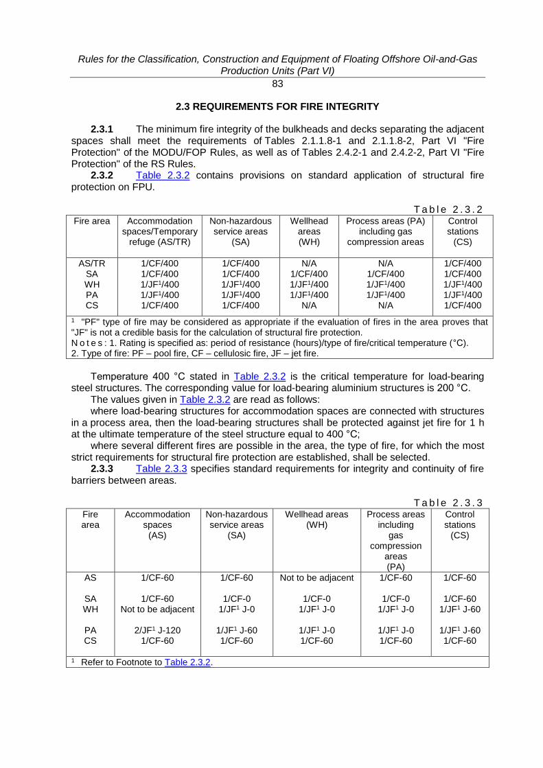
Rules for the Classification, Construction and Equipment of Floating Offshore Oil-and-Gas Production Units (Part VI)
83
2.3 REQUIREMENTS FOR FIRE INTEGRITY
2.3.1 The minimum fire integrity of the bulkheads and decks separating the adjacent spaces shall meet the requirements of Tables 2.1.1.8-1 and 2.1.1.8-2, Part VI "Fire Protection" of the MODU/FOP Rules, as well as of Tables 2.4.2-1 and 2.4.2-2, Part VI "Fire Protection" of the RS Rules.
2.3.2 Table 2.3.2 contains provisions on standard application of structural fire protection on FPU.
T a b l e 2 . 3 . 2 Fire area Accommodation
spaces/Temporary refuge (AS/TR)
Non-hazardous service areas
(SA)
Wellhead areas (WH)
Process areas (PA) including gas
compression areas
Control stations
(CS)
AS/TR SA WH PA CS
1/CF/400 1/CF/400 1/JF1/400 1/JF1/400 1/CF/400
1/CF/400 1/CF/400 1/JF1/400 1/JF1/400 1/CF/400
N/A 1/CF/400 1/JF1/400 1/JF1/400
N/A
N/A 1/CF/400 1/JF1/400 1/JF1/400
N/A
1/CF/400 1/CF/400 1/JF1/400 1/JF1/400 1/CF/400
1 "PF" type of fire may be considered as appropriate if the evaluation of fires in the area proves that "JF" is not a credible basis for the calculation of structural fire protection. N o t e s : 1. Rating is specified as: period of resistance (hours)/type of fire/critical temperature (°С). 2. Type of fire: PF – pool fire, CF – cellulosic fire, JF – jet fire.
Temperature 400 °С stated in Table 2.3.2 is the critical temperature for load-bearing
steel structures. The corresponding value for load-bearing aluminium structures is 200 °С. The values given in Table 2.3.2 are read as follows: where load-bearing structures for accommodation spaces are connected with structures
in a process area, then the load-bearing structures shall be protected against jet fire for 1 h at the ultimate temperature of the steel structure equal to 400 °С;
where several different fires are possible in the area, the type of fire, for which the most strict requirements for structural fire protection are established, shall be selected.
2.3.3 Table 2.3.3 specifies standard requirements for integrity and continuity of fire barriers between areas.
T a b l e 2 . 3 . 3 Fire area
Accommodation spaces
(AS)
Non-hazardous service areas
(SA)
Wellhead areas (WH)
Process areas including
gas compression
areas (PA)
Control stations
(CS)
AS
SA WH
PA CS
1/CF-60
1/CF-60 Not to be adjacent
2/JF1 J-120
1/CF-60
1/CF-60
1/CF-0 1/JF1 J-0
1/JF1 J-60 1/CF-60
Not to be adjacent
1/CF-0 1/JF1 J-0
1/JF1 J-0 1/CF-60
1/CF-60
1/CF-0 1/JF1 J-0
1/JF1 J-0 1/CF-60
1/CF-60
1/CF-60 1/JF1 J-60
1/JF1 J-60 1/CF-60
1 Refer to Footnote to Table 2.3.2.
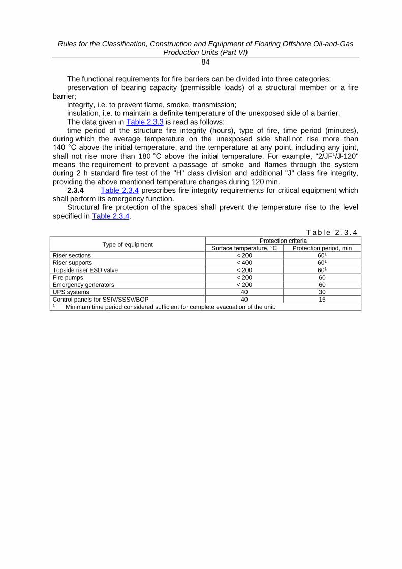
Rules for the Classification, Construction and Equipment of Floating Offshore Oil-and-Gas Production Units (Part VI)
84
The functional requirements for fire barriers can be divided into three categories: preservation of bearing capacity (permissible loads) of a structural member or a fire
barrier; integrity, i.e. to prevent flame, smoke, transmission; insulation, i.e. to maintain a definite temperature of the unexposed side of a barrier. The data given in Table 2.3.3 is read as follows: time period of the structure fire integrity (hours), type of fire, time period (minutes),
during which the average temperature on the unexposed side shall not rise more than 140 °C above the initial temperature, and the temperature at any point, including any joint, shall not rise more than 180 °C above the initial temperature. For example, "2/JF1/J-120" means the requirement to prevent a passage of smoke and flames through the system during 2 h standard fire test of the "H" class division and additional "J" class fire integrity, providing the above mentioned temperature changes during 120 min.
2.3.4 Table 2.3.4 prescribes fire integrity requirements for critical equipment which shall perform its emergency function.
Structural fire protection of the spaces shall prevent the temperature rise to the level specified in Table 2.3.4.
T a b l e 2 . 3 . 4
Type of equipment Protection criteria
Surface temperature, °С Protection period, min
Riser sections < 200 601
Riser supports < 400 601
Topside riser ESD valve < 200 601
Fire pumps < 200 60
Emergency generators < 200 60
UPS systems 40 30
Control panels for SSIV/SSSV/BOP 40 15 1 Minimum time period considered sufficient for complete evacuation of the unit.
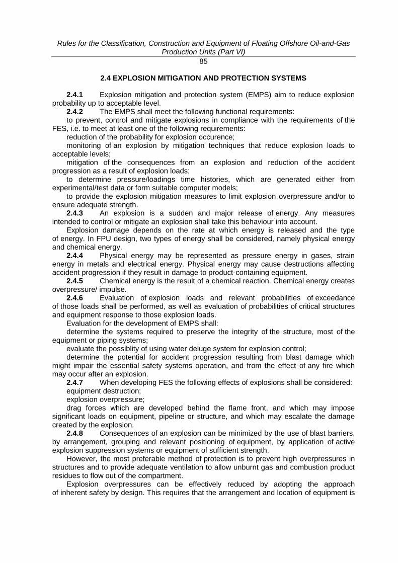
Rules for the Classification, Construction and Equipment of Floating Offshore Oil-and-Gas Production Units (Part VI)
85
2.4 EXPLOSION MITIGATION AND PROTECTION SYSTEMS
2.4.1 Explosion mitigation and protection system (EMPS) aim to reduce explosion probability up to acceptable level.
2.4.2 The EMPS shall meet the following functional requirements: to prevent, control and mitigate explosions in compliance with the requirements of the
FES, i.e. to meet at least one of the following requirements: reduction of the probability for explosion occurence; monitoring of an explosion by mitigation techniques that reduce explosion loads to
acceptable levels; mitigation of the consequences from an explosion and reduction of the accident
progression as a result of explosion loads; to determine pressure/loadings time histories, which are generated either from
experimental/test data or form suitable computer models; to provide the explosion mitigation measures to limit explosion overpressure and/or to
ensure adequate strength. 2.4.3 An explosion is a sudden and major release of energy. Any measures
intended to control or mitigate an explosion shall take this behaviour into account. Explosion damage depends on the rate at which energy is released and the type
of energy. In FPU design, two types of energy shall be considered, namely physical energy and chemical energy.
2.4.4 Physical energy may be represented as pressure energy in gases, strain energy in metals and electrical energy. Physical energy may cause destructions affecting accident progression if they result in damage to product-containing equipment.
2.4.5 Chemical energy is the result of a chemical reaction. Chemical energy creates overpressure/ impulse.
2.4.6 Evaluation of explosion loads and relevant probabilities of exceedance of those loads shall be performed, as well as evaluation of probabilities of critical structures and equipment response to those explosion loads.
Evaluation for the development of EMPS shall: determine the systems required to preserve the integrity of the structure, most of the
equipment or piping systems; evaluate the possiblity of using water deluge system for explosion control; determine the potential for accident progression resulting from blast damage which
might impair the essential safety systems operation, and from the effect of any fire which may occur after an explosion.
2.4.7 When developing FES the following effects of explosions shall be considered: equipment destruction; explosion overpressure; drag forces which are developed behind the flame front, and which may impose
significant loads on equipment, pipeline or structure, and which may escalate the damage created by the explosion.
2.4.8 Consequences of an explosion can be minimized by the use of blast barriers, by arrangement, grouping and relevant positioning of equipment, by application of active explosion suppression systems or equipment of sufficient strength.
However, the most preferable method of protection is to prevent high overpressures in structures and to provide adequate ventilation to allow unburnt gas and combustion product residues to flow out of the compartment.
Explosion overpressures can be effectively reduced by adopting the approach of inherent safety by design. This requires that the arrangement and location of equipment is
Rules for the Classification, Construction and Equipment of Floating Offshore Oil-and-Gas Production Units (Part VI)
86
such as to minimize equipment and pipelines congestion, limit the use of confining walls, limit module volumes and provide adequate ventilation.
2.4.9 The following explosion-mitigation measures shall be provided: to locate equipment in a well ventilated compartment handling products where the
consequences of an explosion are limited or where the explosion-proof structure can be fitted; to limit the number of bulkheads to separate areas or modules; to use grated flooring; to avoid long and narrow modules; to locate process equipment in the open areas, if environmental conditions allow, as
explosion pressure is dependent on the level of congestion and confinement; to avoid significant obstructions, if this cannot be achieved, ventilation outlets in the
bulkheads with frequent obstructions shall be provided. 2.4.10 Where explosion pressure relief valves are provided, they shall be so placed
as to minimize the distance between any potential source of ignition and the valve. Such valves shall have the maximum possible free area, as the arrangement of equipment near them, can have major influence on the maximum overpressures expected in the area.
Main escape routes, essential safety systems and vulnerable process equipment shall not be located in the path of the pressure relief valves, due to possible damage by blast effects and flying fragments. Such equipment shall not be placed close to barriers which may be displaced in the event of an explosion.
Cable trays, junction boxes, pipelines and miscellaneous equipment shall not be allowed to block the explosion pressure relief valves and reduce the free area near them, nor shall they be located in the areas where they will increase turbulence and thus explosion overpressures.
2.4.11 Besides the above said, to minimize explosion effects due to overpressures and drag forces, the following shall be adopted for equipment arrangement:
to minimize number of ignition sources; to orient horizontal pressure vessels in the direction of main ventilation flow; to keep the openings in the module boundaries clear of obstructions; to maximize openings, particularly in floors and ceilings; to take into account that the accuracy of any explosion overpressure prediction is not
fully known, and in particular depends on the prediction technique applied; to provide the maximum strenght of critical equipment/structures/barriers and not to limit
a design by calculated explosion overpressure; to consider explosion suppression by means of ventilation, water sprays, chemicals and
dilution; to perform successive calculation of destruction (failure) so that the accident first occurs
in less critical directions; to minimize the flame spreading; to increase the strength of supports for pipeline, pressurized vessels and equipment to
prevent damage caused by drag forces; to consider the likelihood of impact and damage caused by the flying fragments. The recommended variants of module layout are shown in Fig. 2.4.11.
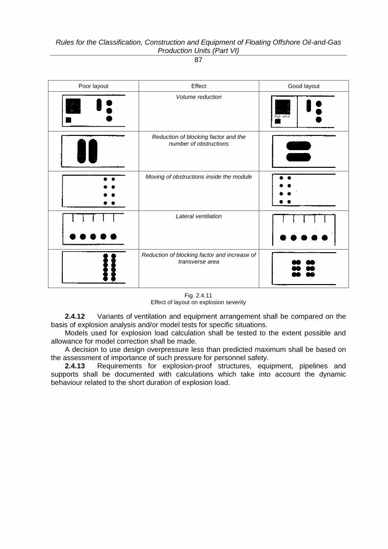
Rules for the Classification, Construction and Equipment of Floating Offshore Oil-and-Gas Production Units (Part VI)
87
Poor layout Effect Good layout
Volume reduction
Reduction of blocking factor and the number of obstructions
Moving of obstructions inside the module
Lateral ventilation
Reduction of blocking factor and increase of transverse area
Fig. 2.4.11 Effect of layout on explosion severity
2.4.12 Variants of ventilation and equipment arrangement shall be compared on the basis of explosion analysis and/or model tests for specific situations.
Models used for explosion load calculation shall be tested to the extent possible and allowance for model correction shall be made.
A decision to use design overpressure less than predicted maximum shall be based on the assessment of importance of such pressure for personnel safety.
2.4.13 Requirements for explosion-proof structures, equipment, pipelines and supports shall be documented with calculations which take into account the dynamic behaviour related to the short duration of explosion load.
Rules for the Classification, Construction and Equipment of Floating Offshore Oil-and-Gas Production Units (Part VI)
88
3 FIRE-FIGHTING EQUIPMENT AND SYSTEMS
3.1 GENERAL
3.1.1 The requirements of this Section apply to all FPU fire-fighting equipment and fire extinguishing systems.
Where provision is made for extra fire-fighting equipment and fire extinguishing systems on FPU in addition to those prescribed by this Section, such equipment and systems may be allowed, provided the requirements thereto in this Section are met.
3.1.2 The fire extinguishing systems shall also meet the requirements of Section 3, Part VI "Fire Protection" and Sections 2, 4 and 5, Part VIII "Systems and Piping" of the RS Rules; Section 3, Part VI "Fire Protection" of the MODU/FOP Rules and Part VIII "Systems and Piping"of the FPU Rules, unless provided otherwise in this Section.
3.1.3 Fire-fighting equipment and fire extinguishing systems shall provide: control of fire and development of accident situation; reduction of fire effect to enable emergency actions or personnel evacuation; fire extinction; reduction of damage to structures and equipment. 3.1.4 Fire-fighting equipment and fire extinguishing systems shall comply with the
following functional requirements: to provide availability of fire-fighting strategy; to meet the recognized standards for specific application; to consider intended purposes and environmental conditions; to provide type approval of the most fire-fighting equipment and system components by
the recognized testing laboratories for specified operating conditions; to provide availability of operating manual; to preclude any effect of actuation time of the fire-fighting equipment and systems on
their ability to perform the intended function; to provide manual shutdown station for automatically activated systems. 3.1.5 The activation of fire-fighting equipment and systems can be automatic,
manual or both. The starting devices depend on the intended location, size and type of fire, and on FES.
3.1.6 The selection of fire-fighting equipment and fire extinguishing system is influenced by many factors, e.g. size and installation complexity, mode of operation, presence of a ship with the mark FF in its class notation and FES availability.
In addition to the water fire main system and in accordance with the purpose for which they are intended, the FPU spaces shall be protected by one of the fixed fire extinguishing systems according to Table 3.1.2 of Part VI "Fire Protection" of the MODU/FOP Rules.
At initial design stage of FPU with the personnel onboard Table 3.1.6 may be used. The final choice of type and quantity of fire-fighting equipment and fire extinguishing
systems shall be based on the fire analysis and assessments of the fire extinguishing systems.
3.1.7 The following spaces shall be protected by automatic fire extinguishing systems:
spaces for diesel-generators and fire pumps with liquid fuel motor drives; accommodation spaces defined in the design on the basis of the fire risk analysis; spaces for electrical equipment (transformers, distribution gears/devices, control
cabinets) without permanent work stations; cable containing spaces (tunnels, ducts, shafts, double floors, galleries, chambers, etc.)
if the cables and wires are rated for 220 V voltage or more and their number is 12 or more.
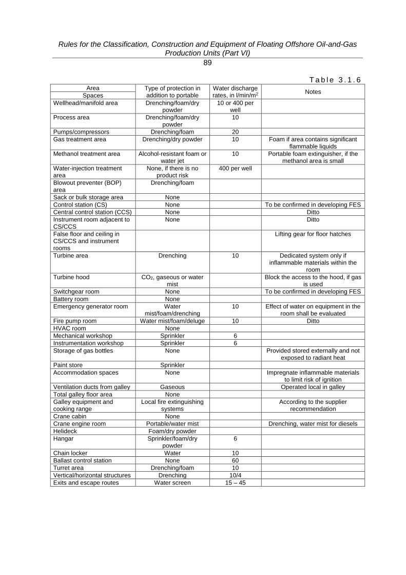
Rules for the Classification, Construction and Equipment of Floating Offshore Oil-and-Gas Production Units (Part VI)
89
T a b l e 3 . 1 . 6 Area Type of protection in
addition to portable Water discharge rates, in l/min/m2
Notes Spaces
Wellhead/manifold area Drenching/foam/dry powder
10 or 400 per well
Process area Drenching/foam/dry powder
10
Pumps/compressors Drenching/foam 20
Gas treatment area Drenching/dry powder 10 Foam if area contains significant flammable liquids
Methanol treatment area Alcohol-resistant foam or water jet
10 Portable foam extinguisher, if the methanol area is small
Water-injection treatment area
None, if there is no product risk
400 per well
Blowout preventer (BOP) area
Drenching/foam
Sack or bulk storage area None
Control station (CS) None To be confirmed in developing FES
Central control station (CCS) None Ditto
Instrument room adjacent to CS/CCS
None Ditto
False floor and ceiling in CS/CCS and instrument rooms
Lifting gear for floor hatches
Turbine area Drenching 10 Dedicated system only if inflammable materials within the
room
Turbine hood CO2, gaseous or water mist
Block the access to the hood, if gas is used
Switchgear room None To be confirmed in developing FES
Battery room None
Emergency generator room Water mist/foam/drenching
10 Effect of water on equipment in the room shall be evaluated
Fire pump room Water mist/foam/deluge 10 Ditto
HVAC room None
Mechanical workshop Sprinkler 6
Instrumentation workshop Sprinkler 6
Storage of gas bottles None Provided stored externally and not exposed to radiant heat
Paint store Sprinkler
Accommodation spaces None Impregnate inflammable materials to limit risk of ignition
Ventilation ducts from galley Gaseous Operated local in galley
Total galley floor area None
Galley equipment and cooking range
Local fire extinguishing systems
According to the supplier recommendation
Crane cabin None
Crane engine room Portable/water mist Drenching, water mist for diesels
Helideck Foam/dry powder
Hangar Sprinkler/foam/dry powder
6
Chain locker Water 10
Ballast control station None 60
Turret area Drenching/foam 10
Vertical/horizontal structures Drenching 10/4
Exits and escape routes Water screen 15 – 45
Rules for the Classification, Construction and Equipment of Floating Offshore Oil-and-Gas Production Units (Part VI)
90
3.1.8 The type of automatic fire extinguishing system, fire-fighting technique, extinguishing medium, etc. shall be determined on the basis of technological, structural, layout and arrangement features of the protected spaces.
3.1.9 Automatic fire extinguishing systems shall include fire detection and alarm system functions.
3.1.10 Fire control stations shall be located outside the areas protected by them.
Rules for the Classification, Construction and Equipment of Floating Offshore Oil-and-Gas Production Units (Part VI)
91
3.2 WATER FIRE MAIN SYSTEM
3.2.1 The water fire main system shall meet the applicable requirements of 3.2.1.5, 3.2.1.10, 3.2.1.11, 3.2.3.4, 3.2.3.5, 3.2.3.7, 3.2.5.2, 3.2.5.3, 3.2.6.1, 3.2.6.6, 3.2.6.9 of Part VI "Fire Protection" of the RS Rules.
3.2.2 The system shall be designed considering structural features of FPU as a multi-level structure and shall include:
ring mains at the level of accommodation spaces; other levels and compartments shall be fitted with pipes branching from the inner fire main with the necessary number of fire monitors (FM), hydrants;
at least two diesel driven fire pumps supplying water to FM, hydrants, pressure water-spraying and foam fire-extinguishing systems (on manned FPU of usual type);
pipelines and shut-off fittings for water supply to fire extinguishing systems (sprinkler, foam, etc.).
3.2.3 Pumps shall be capable of delivering sea water. The water treatment shall be provided if fouling can impair the system operation, as well as input filter shall be fitted if the FPU waste can damage the pump.
3.2.4 The capacity and head of each fire pump shall be sufficient to ensure simultaneous operation of water or foam fire extinguishing systems and hand fire monitors for design basis fire and are determined by calculation.
3.2.5 As a rule, the system shall cover one most probable fire zone (if water drenching systems are provided) and some hand fire-fighting equipment (jets from FM/hoses). If FES requires, the fire containment measures and any planned temporary drenching systems shall be considered.
3.2.6 The capacity of fire pumps is chosen so that they shall be capable of delivering sufficient amount of water to the systems consuming it in operation.
3.2.7 The capacity of an emergency fire pump shall provide the fire main pressure for fire-fighting and drenching in case of a fire specified in 3.2.5.
3.2.8 The fire pumps shall be located in different FPU compartments so as not to be damaged simultaneously in the event of an accident. The compartments shall be equipped with an automatic fire alarm system.
3.2.9 The fire pumps shall be connected with the sea water collector below the unit waterline and protected from penetration of ice and bottom suspended matter.
The fire pumps inlets shall be separated so that in case of failure of one pump the other pump inlet remains operable.
3.2.10 Possibility of inspection of the system functioning within the whole range of its operational characteristics shall be provided.
3.2.11 Fire pump relief pressure valves may be required to prevent damage to the pipeline due to high working pressures.
3.2.12 Sea water storage tanks shall meet the requirements of 3.3.2, Part VIII "Systems and Piping" of the MODU/FOP Rules.
The capacity of the tanks shall be such that minimum permissible amount of water therein permits the operation of at least one fire hose nozzle whithin 15 min, but in any case the capacity shall be not less than 10 m3.
Where fixed foam fire extinguishing system is provided, the capacity of the tanks shall be such that minimum permissible amount of water therein permits the operation of at least one fire hose nozzle whithin 15 min and at least one foam unit whithin 30 min, but in any case the capacity shall not be less than 20 m3.
3.2.13 The fire pumps diesel engines shall be fitted with independent fuel tanks. Reserves of fuel shall provide continuous pump operation for at least 6 h.
Rules for the Classification, Construction and Equipment of Floating Offshore Oil-and-Gas Production Units (Part VI)
92
3.2.14 All seawater consumers on FPU (except fire pumps) shall be automatically disconnected from the seawater supply system in case of fire. The said requirement does not apply to separate water supply systems for fire-fighting and other seawater consumers.
3.2.15 The required parameters of water in the ring fire main shall be constantly maintained.
3.2.16 Fire pumps shall be started: automatically: upon receiving the fire detection signal, upon receiving the signal of low pressure in the ring fire mains, upon receiving the signal from the manual fire detectors; manually: from the button in CCS, from the button in TR, from the button on helideck (if available). If the communication with the control room is lost the fire pumps shall be started
automatically. 3.2.17 The indicators of the fire main water pressure drop shall be provided in CCS. 3.2.18 Once started, the fire pump may be switched off only manually. 3.2.19 Fire pumps shall be located and protected so that they will be capable to
deliver water during the fire. Protection from damage to the associated power cables, hydraulic systems/pipeline and control circuits shall be provided.
3.2.20 The system shall be fitted with cut-off valves allowing, if necessary, disconnection of only one fire pump during maintenance operations or repairs.
3.2.21 The ring mains shall be routed so that the unit metal structures can screen them from possible fire or impact damage.
3.2.22 The system shall be provided with devices sending signals to CCS about remote opening and closing of shut-off fittings.
3.2.23 The fire main shall be provided with branch pipes for receiving water from service and fire-fighting vessels. The branch pipes shall be located on the FPU opposite sides.
3.2.24 The FPU protected by water fire main system shall be provided with at least one international shore connection in compliance with 5.1.18, Part VI "Fire Protection" of the RS Rules, by means of which water can be delivered to the TS water fire main system if this is required for fire-fighting on board the ship.
3.2.25 The ring fire mains shall be equipped with the necessary fittings and connections for testing, holding periodical checks, washing and air venting during the initial filling.
3.2.26 The fire hydrants arrangement and the length of hoses shall ensure the delivery of at least two jets of water from different hydrants to any FPU area.
3.2.27 Each fire hydrant shall be provided with a fire hose of equal diameter and sufficient (as a rule, up to 25 m) length and with a fire hose nozzle capable of both jet and spray discharge of water/foam.
3.2.28 The fire hoses contained in the lockers shall be connected to the fire hydrants and nozzles.
3.2.29 The places where the fire hydrants are located and fire extinguishing systems are activated shall be fitted with lighted or fluorescent signs and emergency lighting.
3.2.30 The connection of fire hydrants and fire monitors to the fire main shall be such that shutoff of water supply to the sprinkler or foam fire extinguishing systems shall not disrupt water supply to fire hydrants or fire monitors in this area.
3.2.31 Fire monitors (FM) may be used to provide water-spraying, foam fire extinguishing or drenching.

Rules for the Classification, Construction and Equipment of Floating Offshore Oil-and-Gas Production Units (Part VI)
93
3.2.31.1 The design of monitors shall consider their location, diameter of the supply pipe, arrangement of control valves and environment conditions.
3.2.31.2 A fire monitor may be remotely or locally started and operated. Remotely started monitors shall be arranged so that they cannot cause injury or block escape routes when operated. Any remotely operated monitor shall be provided with local manual override control.
3.2.31.3 The monitor shall be provided with an access far removed from the unit protected area and so located as to protect an operator from the effects of heat radiated by the fire, unless the monitor is started only automatically/remotely.
3.2.31.4 Each monitor shall have sufficient movement horizontally and vertically in order to permit the monitor to cover the FPU complete area of protection. Monitors shall be provided with locking devices.
Rules for the Classification, Construction and Equipment of Floating Offshore Oil-and-Gas Production Units (Part VI)
94
3.3 DRENCHING SYSTEM
3.3.1 Fixed drenching system may be used: to control of pool fires and thus reduce the fire spread probability; to provide cooling of equipment and structures not impinged by jet fires; to limit effects of fires to facilitate emergency response and EER activities. 3.3.2 The drenching system is intended to protect: areas with the pipelines and equipment directly related to production; critical equipment such as pressure vessels and well heads; specific structural members; personnel during escape and evacuation by reducing heat radiation and smoke
spreading. 3.3.3 When designing drenching system the following shall be taken into account: approved technique for hydraulic analysis shall be used; water pressure available at the inlet to the system or an individual section shall be sufficient
for the efficient operation of all nozzles in that system or section under design water rate; selected nozzle type, location and operation shall be suitable for the fulfilment of the
system function during a fire; size of nozzles and associated pipeline shall be selected to prevent them from becoming
clogged by corrosion products; nozzles location and orientation shall be so that to ensure the supply of the required
quantity of water on the protected surfaces; expected time of system operation shall be at least 3 h. 3.3.4 Release of the system shall be possible both manually at the fire risk area and
remotely at the control station where the operating status of the system (e.g. "valve is open/closed") is monitored.
3.3.5 Piping shall be designed to be robust and adequately secured and supported, as well as protected against the effects of fires and explosions (with due account to the oscillations).
3.3.6 Means shall be provided to enable the valve testing without discharging water through the pipeline and nozzles.

Rules for the Classification, Construction and Equipment of Floating Offshore Oil-and-Gas Production Units (Part VI)
95
3.4 PRESSURE WATER-SPRAYING SYSTEM
3.4.1 When evaluating pressure water-spraying system the following shall be considered:
system suitability for specific application; sufficient water and air supply; size of the area to be protected and arrangement of the equipment; the fuel type and the nature of the occurring fire; effect on electrical and other sensitive equipment within the area of pressure water-
spraying system application. 3.4.2 At a first approximation it is recommended to use applicable requirements
specified in 3.4, Part VI "Fire Protection" of the RS Rules.
Rules for the Classification, Construction and Equipment of Floating Offshore Oil-and-Gas Production Units (Part VI)
96
3.5 FOAM FIRE EXTINGUISHING SYSTEM
3.5.1 FPU shall be provided with a fixed deck foam fire extinguishing system. 3.5.2 Foam fire extinguishing system shall meet the applicable requirements of 3.7,
Part VI "Fire Protection" of the RS Rules. 3.5.3 The estimated time for fire extinguishing shall be taken equal to 15 min. 3.5.4 The deck in way of cargo tanks (CT) and CT themselves shall be protected by
a fixed deck foam fire extinguishing system or equivalent fixed fire extinguishing system approved by the Register.
The requirements of 3.1.4, Part VI "Fire Protection" of the MODU/FOP Rules shall be also considered.
The installation of fixed deck foam fire extinguishing system is not obligatory if FPU is designed to prevent product penetration onto the upper deck and if the unit hull is not intended for product storage.
3.5.5 Provisions shall be made for the installation in the FPU process areas of fixed foam generators connected to the foam solution distribution pipeline which provides foam supply sufficient to cover the whole area but not less than 500 m2.
3.5.6 The installation shall provide foam solution discharge rate of at least 0,08 l/s per m2.
3.5.7 The foam generators shall be equally spaced along the FPU perimeter. 3.5.8 Sufficient foam concentrate and water shall be supplied to ensure foam
solution generation in the volume equal to 3-fold supply. The percentage of foam concentrate in the solution is determined depending on the type of foam concentrate and the water used (fresh or sea water). To increase the resistance of medium expansion mechanical foam (expansion ratio 80 – 100) to the effect of sea water, the foam concentration in the solution shall be at least 12 %.
3.5.9 The number of portable foam generators, foam applicators or portable combination foam units shall be determined by calculations. For making such calculations Table 3.7.1.3 shall be used and requirements of 3.7.2.3, Part VI "Fire Protection" of the RS Rules shall be considered.
In all cases FPU shall be equipped with at least one portable foam generator, or one foam applicator, or one portable combination foam unit of the required capacity. This number of the said devices shall be confirmed by the appropriate calculation.
3.5.10 Supply system may be constantly filled with the solution of foam concentrate or be dry (not filled with the solution). The possibility of using dry system is determined by calculation.
3.5.11 The system allowable response time from the moment of fire occurrence including the time of sensors (detectors) activation shall not exceed 3 min.
3.5.12 On the supply pipelines (delivering water and foam) at every process area, the installation of fire hydrants or manifolds with coupling heads shall be provided for connecting ships with the mark FF in their class notation and supply vessels with the valves to provide water and foam concentrate delivery into the FPU system.
3.5.13 The pipeline valves, as well as fire hydrants, manifolds and other fire-fighting equipment shall be manufactured in accordance with the Register requirements.
3.5.14 The number and location of manifolds shall be in compliance with the calculation based on the required quantities of water and foam solution for fire extinction but it shall be not less than two for each process area.
3.5.15 The manifolds shall be provided with common gate fitted directly at the supply pipeline, as well as with valves at each coupling head and drainage arrangements.
Rules for the Classification, Construction and Equipment of Floating Offshore Oil-and-Gas Production Units (Part VI)
97
3.5.16 The fixed foam fire extinguishing system of the FPU helideck shall meet the requirements in 6.4.1, Part XVII "Distinguishing Marks and Descriptive Notations in the Class Notation Specifying Structural and Operational Particulars of Ships" of the RS Rules.
3.5.17 The hoses of the ship with the mark FF in its class notation shall be easily accessible, located near the ends of fire mains, preferably in the areas where the ships may safely moor and shall make it possible to connect four hoses, each 64 mm in diameter. The system inlet openings shall be provided with valves.

Rules for the Classification, Construction and Equipment of Floating Offshore Oil-and-Gas Production Units (Part VI)
98
3.6 SPRINKLER SYSTEM
3.6.1 Automatic sprinkler system shall be used in areas where cellulosic fires are expected.
3.6.2 The system shall meet the applicable requirements of 3.3, Part VI "Fire Protection" of the RS Rules.
Rules for the Classification, Construction and Equipment of Floating Offshore Oil-and-Gas Production Units (Part VI)
99
3.7 DRY POWDER SYSTEM
3.7.1 Fixed dry powder system shall provide effective fire extinguishing. The nature of potential fires shall be considered in selecting the type of dry powder and equipment.
3.7.2 When powder and foam concentrate are expected to be used at the same location, their compatibility shall be confirmed.
Self-contained combined systems are available for simultaneous or sequential use of foam and dry powder.
3.7.3 Portable dry powder fire extinguishers or fixed systems may be used. 3.7.4 Dry powder systems shall meet the applicable requirements of 3.10, Part VI
"Fire Protection" of the RS Rules. 3.7.5 Several powder fire extinction stations may be used.
Rules for the Classification, Construction and Equipment of Floating Offshore Oil-and-Gas Production Units (Part VI)
100
3.8 WATER-SCREEN SYSTEM
3.8.1 Water-screen system wall shall be provided in the FPU process area. The design length of the water-screen shall be taken equal to the length of the process area plus 10 m in both directions or equal to the length of cylindrical part of the cargo ship hull if mooring alongside is provided. Sea water may be used in the water-screen system.
3.8.2 The quantity of water, water-screen nozzles, capacity and pressure head, as well as inner diameter of the supply and distribution pipelines shall be calculated so that to provide a continuous water screen of at least 3 m higher above the cargo deck level at the beginning of loading. The pressure head in the water-screen system pipes shall be at least 0,7 MPa.
3.8.3 The distance between the nozzles shall not exceed 0,5 m. The minimum water discharge rate shall be at least 1 l/s per 1 linear metre of the screen length.
3.8.4 The fire main, considering the quantity of water necessary for the sufficient operation of the water-screen system, shall provide the water discharge rate for cooling metal structures of 0,05 l/s per 1,0 m2 or 0,1 l/s per 1,0 m of the process area length plus 10 m outside the area.
3.8.5 Water screens can be used to protect escape routes and survival craft embarkation stations against heat radiation from possible fires.
3.8.6 The activation of the water screen systems shall be performed both manually, from the place of possible fire, and remotely.
Rules for the Classification, Construction and Equipment of Floating Offshore Oil-and-Gas Production Units (Part VI)
101
4 FIRE DETECTION AND ALARM SYSTEMS
4.1 GENERAL
4.1.1 Fire detection and alarm systems shall meet the requirements of 4.1, Part VI "Fire Protection" of the RS Rules.
4.1.2 Fire detection and alarm systems shall be designed to serve the following purposes:
fire, smoke, inflammable gases detection; continuous automatic monitoring to warn the personnel of fire or explosion hazard. Fire detection and alarm systems shall provide manual or automatic control. 4.1.3 Fire detection and alarm systems shall meet the following functional
requirements: ensure compliance with the FES requirements; have devices to allow testing of the arrangements and system internal functions; control and alarm panel shall be easily accessible at a permanently manned control
station; visual alarm signal shall be given for personnel assembly, and supplemented with the
audible alarm signal in high-noise areas. 4.1.4 Fire detection and alarm systems shall solve the following tasks: initiate EDP; isolate electrical equipment to prevent further propagation of fire; ventilation shutdown; activate fire extinguishing systems where they are intended for monitoring or mitigation
of product ignition; initiate personnel assembly. 4.1.5 Monitoring functions of fire detection and alarm systems shall provide
detection of the following: hazardous accumulations of gases/oil mist; pump seal leaks; fires in the early stage. 4.1.6 Fire detection and alarm systems shall have the following functions: manual activation of alarm signal; indication of fire location or hazardous accumulation of inflammable gases or oil mist.
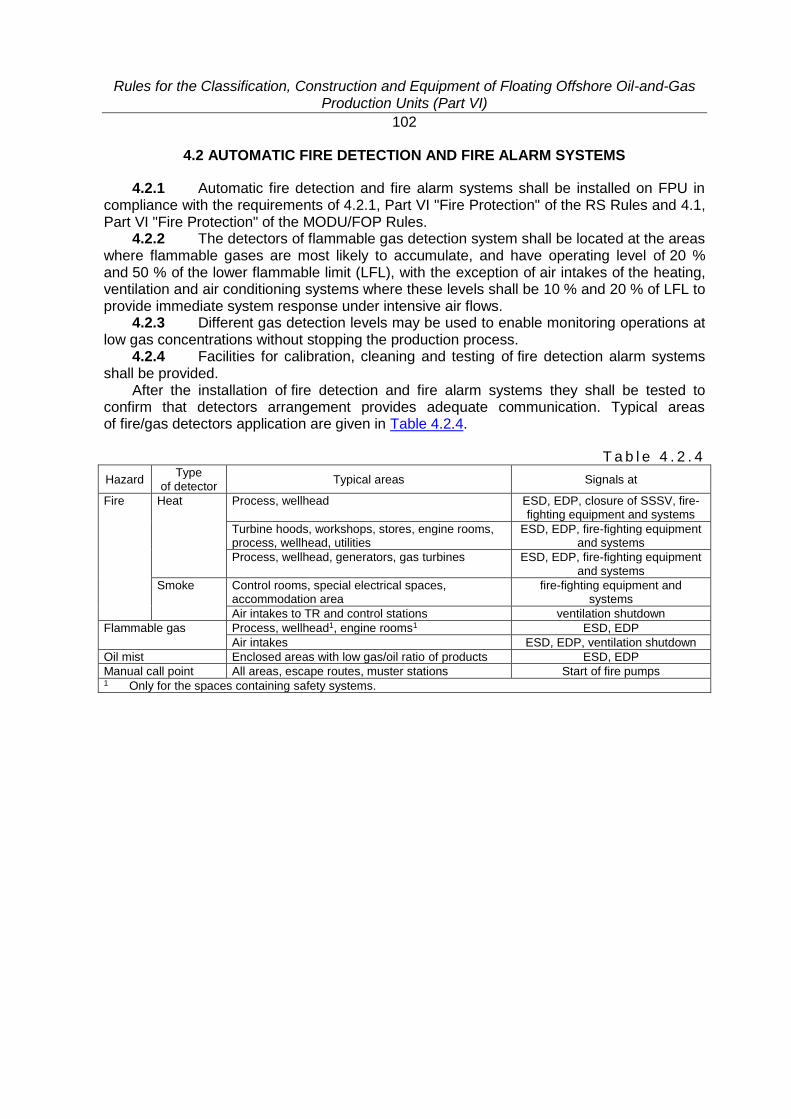
Rules for the Classification, Construction and Equipment of Floating Offshore Oil-and-Gas Production Units (Part VI)
102
4.2 AUTOMATIC FIRE DETECTION AND FIRE ALARM SYSTEMS
4.2.1 Automatic fire detection and fire alarm systems shall be installed on FPU in compliance with the requirements of 4.2.1, Part VI "Fire Protection" of the RS Rules and 4.1, Part VI "Fire Protection" of the MODU/FOP Rules.
4.2.2 The detectors of flammable gas detection system shall be located at the areas where flammable gases are most likely to accumulate, and have operating level of 20 % and 50 % of the lower flammable limit (LFL), with the exception of air intakes of the heating, ventilation and air conditioning systems where these levels shall be 10 % and 20 % of LFL to provide immediate system response under intensive air flows.
4.2.3 Different gas detection levels may be used to enable monitoring operations at low gas concentrations without stopping the production process.
4.2.4 Facilities for calibration, cleaning and testing of fire detection alarm systems shall be provided.
After the installation of fire detection and fire alarm systems they shall be tested to confirm that detectors arrangement provides adequate communication. Typical areas of fire/gas detectors application are given in Table 4.2.4.
T a b l e 4 . 2 . 4
Hazard Type
of detector Typical areas Signals at
Fire Heat Process, wellhead ESD, EDP, closure of SSSV, fire-fighting equipment and systems
Turbine hoods, workshops, stores, engine rooms, process, wellhead, utilities
ESD, EDP, fire-fighting equipment and systems
Process, wellhead, generators, gas turbines ESD, EDP, fire-fighting equipment and systems
Smoke Control rooms, special electrical spaces, accommodation area
fire-fighting equipment and systems
Air intakes to TR and control stations ventilation shutdown
Flammable gas Process, wellhead1, engine rooms1 ESD, EDP
Air intakes ESD, EDP, ventilation shutdown
Oil mist Enclosed areas with low gas/oil ratio of products ESD, EDP
Manual call point All areas, escape routes, muster stations Start of fire pumps 1 Only for the spaces containing safety systems.
Rules for the Classification, Construction and Equipment of Floating Offshore Oil-and-Gas Production Units (Part VI)
103
4.3 MANUAL FIRE ALARMS
4.3.1 Manual fire alarms shall be provided on FPU in compliance with the requirements of 4.2.2, Part VI "Fire Protection" of the RS Rules and 4.2 of Part VI "Fire Protection" of the MODU/FOP Rules.
4.3.2 Manual call points shall be easily accessible and located so that the personnel will be able to give an alarm signal in a hazardous situation and immediately start the prescribed actions.

Rules for the Classification, Construction and Equipment of Floating Offshore Oil-and-Gas Production Units (Part VI)
104
4.4 FIRE DETECTION AND FIRE ALARM SYSTEM OF UNMANNED SINGLE POINT MOORING
4.4.1 Fire detection and fire alarm system of unmanned SPM and unattended machinery spaces shall meet the requirements of 4.2.3, Part VI "Fire Protection" of the RS Rules.
4.4.2 For accommodation protection an automatic water fire main system shall be provided, while for other spaces an automatic gas fire extinguishing system shall be actuated, and alarms shall be given by an automatic fire alarm and detection system.
4.4.3 All fire extinguishing systems shall be activated remotely from the FPU control station.
Rules for the Classification, Construction and Equipment of Floating Offshore Oil-and-Gas Production Units (Part VI)
105
4.5 GAS DETECTION AND ALARM SYSTEMS AND EQUIPMENT
4.5.1 Fixed automatic gas detection and alarm systems shall be provided on FPU in compliance with the requirements of 4.3, Part VI "Fire Protection" of the MODU/FOP Rules.
4.5.2 Where smoke generation and gas ignition may be expected to occur in the temporary refuge, the fire detection and alarm systems shall be worked out for giving signals to provide closing of the ventilation systems before gas reaches the temporary refuge.
4.5.3 Electrical, electronic and programmable devices of detectors shall meet the requirements for ESD.
4.5.4 Temporary shutdown of the fire detection and alarm systems, or part of the system, is reasonable if adequate alternative arrangements are provided.
4.5.5 The fire detection and alarm system control scheme shall be designed, located or protected so that it will be available in hazardous situations where fire and gas detection is required.
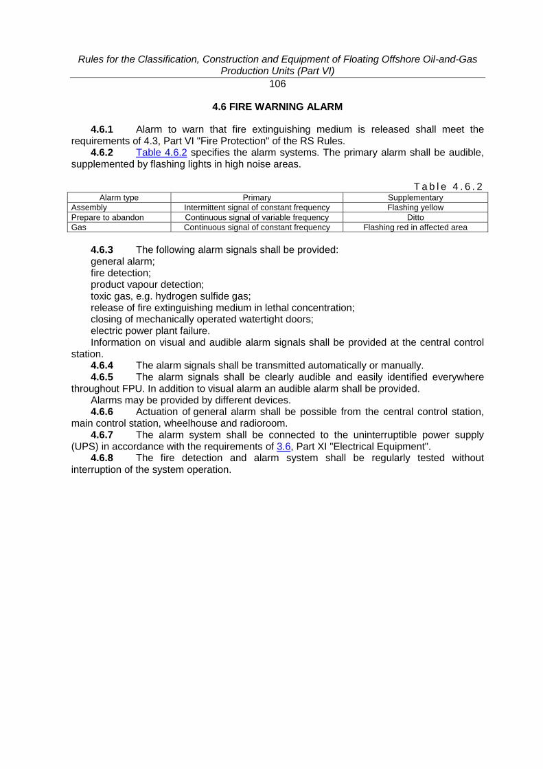
Rules for the Classification, Construction and Equipment of Floating Offshore Oil-and-Gas Production Units (Part VI)
106
4.6 FIRE WARNING ALARM
4.6.1 Alarm to warn that fire extinguishing medium is released shall meet the requirements of 4.3, Part VI "Fire Protection" of the RS Rules.
4.6.2 Table 4.6.2 specifies the alarm systems. The primary alarm shall be audible, supplemented by flashing lights in high noise areas.
T a b l e 4 . 6 . 2 Alarm type Primary Supplementary
Assembly Intermittent signal of constant frequency Flashing yellow
Prepare to abandon Continuous signal of variable frequency Ditto
Gas Continuous signal of constant frequency Flashing red in affected area
4.6.3 The following alarm signals shall be provided: general alarm; fire detection; product vapour detection; toxic gas, e.g. hydrogen sulfide gas; release of fire extinguishing medium in lethal concentration; closing of mechanically operated watertight doors; electric power plant failure. Information on visual and audible alarm signals shall be provided at the central control
station. 4.6.4 The alarm signals shall be transmitted automatically or manually. 4.6.5 The alarm signals shall be clearly audible and easily identified everywhere
throughout FPU. In addition to visual alarm an audible alarm shall be provided. Alarms may be provided by different devices. 4.6.6 Actuation of general alarm shall be possible from the central control station,
main control station, wheelhouse and radioroom. 4.6.7 The alarm system shall be connected to the uninterruptible power supply
(UPS) in accordance with the requirements of 3.6, Part XI "Electrical Equipment". 4.6.8 The fire detection and alarm system shall be regularly tested without
interruption of the system operation.
Rules for the Classification, Construction and Equipment of Floating Offshore Oil-and-Gas Production Units (Part VI)
107
5 FIRE-FIGHTING OUTFIT, SPARE PARTS AND TOOLS
5.1 GENERAL
5.1.1 Spare parts and tools shall meet the applicable requirements of 5.2, Part VI "Fire Protection"of the RS Rules, unless otherwise stated.
5.1.2 Items of fire-fighting outfit shall be of approved type and be ready for use at any time. Fire-fighting outfit shall be located in a readily accessible place.
5.1.3 As a minimum, the fire-fighting outfit shall comply with 5.1, Part VI "Fire Protection" of the RS Rules as applied to oil tankers and shall ensure fire fighting in the process area.
5.1.4 Additionally, FPU equipped with helidecks shall be provided with fire-fighting outfit in compliance with 6.4.1.15, Part XVII "Distinguishing Marks and Descriptive Notations in the Class Notation Specifying Structural and Operational Particulars of Ships" of the RS Rules.
5.1.5 Spare parts for fire extinguishing systems and tools (except one set of fire tools) may be kept in the appropriate shore base.
Rules for the Classification, Construction and Equipment of Floating Offshore Oil-and-Gas Production Units (Part VII)
108
PART VII. MACHINERY INSTALLATIONS
1 GENERAL
1.1 APPLICATION
1.1.1 The requirements of this Part apply to the machinery installations, equipment of machinery spaces, shafting lines, propellers, machinery condition monitoring systems, spare parts and active means of steering ensuring functioning of a floating offshore structure or a unit for its intended purpose and observance of safety requirements thereon.
The said equipment is also covered by the applicable requirements of Part VII "Machinery Installations"of the RS Rules and Part VII "Machinery Installations and Machinery" of the MODU/FOP Rules.
1.1.2 On FPU without machinery spaces but provided with machinery and arrangements for functioning of FPU for its intended purpose, the requirements of this Part are applied to the extent that is reasonable and practicable.
Rules for the Classification, Construction and Equipment of Floating Offshore Oil-and-Gas Production Units (Part VII)
109
1.2 DEFINITIONS AND EXPLANATIONS
1.2.1 Definitions and explanations are given in the General Regulations for Classification and Other Activity, in Part I "Classification" and Part VII "Machinery Installations" of the RS Rules, in Parts I "Classification" and VII "Machinery Installations and Machinery" of the MODU/FOP Rules as well as Part I "Classification", Part III "Equipment, Arrangements and Outfit" and Part VI "Fire and Explosion Protection" of the FPU Rules.
Rules for the Classification, Construction and Equipment of Floating Offshore Oil-and-Gas Production Units (Part VII)
110
1.3 SCOPE OF TECHNICAL SUPERVISION
1.3.1 General provisions covering the procedure of classification, technical supervision during construction, as well as technical documentation to be submitted to the Register for consideration and approval are stated in the General Regulations for Classification and Other Activity and in Part I "Classification" of the RS Rules, in Part I "Classification" of the MODU/FOP Rules and in Part I "Classification" of the FPU Rules.
1.3.2 During FPU construction, the manufacture, installation and testing of component parts of machinery installation are subject to technical supervision by the Register in compliance with 1.3, Part VII "Machinery Installations" of the RS Rules.
Rules for the Classification, Construction and Equipment of Floating Offshore Oil-and-Gas Production Units (Part VII)
111
2 GENERAL REQUIREMENTS
2.1 POWER OF MAIN MACHINERY
2.1.1 The power of ship-shaped self-propelled FPU shall meet the requirements of 2.1, Part VII "Machinery Installations" of the RS Rules.

Rules for the Classification, Construction and Equipment of Floating Offshore Oil-and-Gas Production Units (Part VII)
112
2.2 NUMBER OF MAIN BOILERS
2.2.1 The number of main boilers when a steam power plant is used shall be substantiated.
Rules for the Classification, Construction and Equipment of Floating Offshore Oil-and-Gas Production Units (Part VII)
113
2.3 ENVIRONMENTAL CONDITIONS
2.3.1 Environmental conditions shall meet the requirements stated in 2.3.1, Part VII "Machinery Installations" of the RS Rules.
2.3.2 Main and auxiliary machinery, as well as emergency machinery and equipment on the ship-shaped self-propelled FPU in transit shall meet the requirements of Table 2.3.1-1, Part VII "Machinery Installations" of the RS Rules.
2.3.3 All machinery, equipment and systems which ensure safe operation of non-self-propelled FPU, ship-shaped and non-ship shaped, as well as manned FSPM shall remain operable at static inclination of 15°, dynamic inclination of 22,5° inclusive, in any direction.
2.3.4 Operating conditions of the machinery installation of SSPM and unmanned FSPM used in marine operations shall be specified in the documentation and substantiated with regard to 2.3.5.
2.3.5 The values of inclinations given in 2.3.2 – 2.3.4 may be changed depending on the FPU type, size and operating conditions, at that the appropriate substantiation shall be submitted to the Register for review.

Rules for the Classification, Construction and Equipment of Floating Offshore Oil-and-Gas Production Units (Part VII)
114
2.4 MATERIALS
2.4.1 Materials for the manufacture of parts of the shafting and propellers of self-propelled FPU shall meet the requirements of 2.4, Part VII "Machinery Installations" of the RS Rules.
Rules for the Classification, Construction and Equipment of Floating Offshore Oil-and-Gas Production Units (Part VII)
115
2.5 INDICATING INSTRUMENTS
2.5.1 All the indicating instruments shall meet the requirements of 2.5, Part VII "Machinery Installations" of the RS Rules.
Rules for the Classification, Construction and Equipment of Floating Offshore Oil-and-Gas Production Units (Part VII)
116
2.6 APPLICATION OF RELIABILITY MEASURES
2.6.1 The reliability measures are established in compliance with the requirements of 2.6, Part VII "Machinery Installations" of the RS Rules.

Rules for the Classification, Construction and Equipment of Floating Offshore Oil-and-Gas Production Units (Part VII)
117
2.7 FUEL OIL
2.7.1 Fuel oil used on FPU shall meet the requirements of 1.1.2, Part VII "Machinery Installations" of the RS Rules.
2.7.2 Crude oil may be used as fuel for boilers providing that the requirements of 13.11, Part VIII "Systems and Piping" of the RS Rules are met.
2.7.3 Natural gas (methane) may be used as fuel for dual-fuel internal combustion engines (ICE), provided that the requirements of 13.12, Part VIII "Systems and Piping" and Section 9, Part IX "Machinery" of the RS Rules are met.

Rules for the Classification, Construction and Equipment of Floating Offshore Oil-and-Gas Production Units (Part VII)
118
3 CONTROL DEVICES AND STATIONS. MEANS OF COMMUNICATION
3.1 CONTROL DEVICES
3.1.1 Control devices of self-propelled FPU shall meet the requirements of 3.1, Part VII "Machinery Installations" of the RS Rules.
Rules for the Classification, Construction and Equipment of Floating Offshore Oil-and-Gas Production Units (Part VII)
119
3.2 CONTROL STATIONS
3.2.1 The bridge control stations of main engines and propellers, as well as main machinery control room on self-propelled FPU shall be equipped in compliance with the requirements of 3.2.1, Part VII "Machinery Installations" of the RS Rules.
3.2.2 Main machinery control room and cargo control room (CCR) shall be located as far from machinery spaces as practicable.
3.2.3 CCR shall be equipped with means of communication, control devices, means of monitoring and alarm devices in compliance with the requirements of 3.2.11, Part VII "Machinery Installations" of the RS Rules.
Rules for the Classification, Construction and Equipment of Floating Offshore Oil-and-Gas Production Units (Part VII)
120
3.3 MEANS OF COMMUNICATION
3.3.1 At least two independent means shall be provided for communicating orders from the navigating bridge of self-propelled FPU to the position in the engine room or in the main machinery control room meeting the requirements of 3.3.1, Part VII "Machinery Installations" of the RS Rules.
3.3.2 Two-way communication shall be provided between: CCR and navigating bridge on self-propelled FPU; CCR and spaces containing cargo and ballast pumps; process control station, CCR, main machinery control room and other spaces containing
equipment essential for the FPU safety.
Rules for the Classification, Construction and Equipment of Floating Offshore Oil-and-Gas Production Units (Part VII)
121
4 MACHINERY SPACES. ARRANGEMENT OF MACHINERY AND EQUIPMENT
4.1 ARRANGEMENT OF MACHINERY AND EQUIPMENT
4.1.1 Arrangement of machinery and equipment shall meet the requirements of 4.2, Part VII "Machinery Installations" of the RS Rules and 2.3, Part VII "Machinery Installations and Machinery" of the MODU/FOP Rules.

Rules for the Classification, Construction and Equipment of Floating Offshore Oil-and-Gas Production Units (Part VII)
122
4.2 ARRANGEMENT OF FUEL OIL TANKS
4.2.1 Arrangement of fuel oil tanks shall meet the requirements of 4.3, Part VII "Machinery Installations" of the RS Rules.

Rules for the Classification, Construction and Equipment of Floating Offshore Oil-and-Gas Production Units (Part VII)
123
4.3 INSTALLATION OF MACHINERY AND EQUIPMENT
4.3.1 Installation of machinery and equipment shall meet the requirements of 4.4, Part VII "Machinery Installations" of the RS Rules.

Rules for the Classification, Construction and Equipment of Floating Offshore Oil-and-Gas Production Units (Part VII)
124
4.4 MEANS OF ESCAPE FROM MACHINERY SPACES
4.4.1 Means of escape from machinery spaces shall meet the requirements of 4.5, Part VII "Machinery Installations"of the RS Rules and 2.6, Part VII "Machinery Installations and Machinery" of the MODU/FOP Rules.

Rules for the Classification, Construction and Equipment of Floating Offshore Oil-and-Gas Production Units (Part VII)
125
4.5 INSULATION OF HEATED SURFACES
4.5.1 Insulation of heated surfaces shall meet the requirements of 4.6, Part VII "Machinery Installations" of the RS Rules.

Rules for the Classification, Construction and Equipment of Floating Offshore Oil-and-Gas Production Units (Part VII)
126
5 SHAFTING AND PROPELLERS
5.1 Shafting and propellers of self-propelled FPU shall meet the requirements of Sections 5 and 6, Part VII "Machinery Installations" of the RS Rules, respectively.

Rules for the Classification, Construction and Equipment of Floating Offshore Oil-and-Gas Production Units (Part VII)
127
6 DYNAMIC POSITIONING SYSTEM
6.1 The steerable propellers of the dynamic positioning system shall meet the requirements of Section 7, Part VII "Machinery Installations" of the RS Rules.
Rules for the Classification, Construction and Equipment of Floating Offshore Oil-and-Gas Production Units (Part VII)
128
7 TORSIONAL VIBRATION
7.1 Torsional vibration calculations of propulsion plants, diesel-generators and ICE-driven auxiliary machinery shall be made in compliance with the requirements of Section 8, Part VII "Machinery Installations" of the RS Rules.
Rules for the Classification, Construction and Equipment of Floating Offshore Oil-and-Gas Production Units (Part VII)
129
8 VIBRATION OF MACHINERY AND EQUIPMENT
8.1 The allowable vibration level of the FPU machinery and equipment shall meet the vibration standards given in Section 9, Part VII "Machinery Installations" of RS the Rules.

Rules for the Classification, Construction and Equipment of Floating Offshore Oil-and-Gas Production Units (Part VII)
130
9 SPARE PARTS AND TOOLS
9.1 The main machinery shall be supplied with a set of appropriate tools and appliances necessary for dismantling and assembling of the machinery in service conditions. The recommended list of the spare parts is given in Appendix 1 to Part VII "Machinery Installations" of the RS Rules.
Rules for the Classification, Construction and Equipment of Floating Offshore Oil-and-Gas Production Units (Part VII)
131
10 MACHINERY TECHNICAL CONDITION MONITORING SYSTEM
10.1 When the technical condition monitoring and control system is applied to the FPU classification survey on the basis of the Planned Maintenance Scheme, it shall meet the requirements of Section 10, Part VII "Machinery Installations" of the RS Rules.
Rules for the Classification, Construction and Equipment of Floating Offshore Oil-and-Gas Production Units (Part VIII)
132
PART VIII. SYSTEMS AND PIPING
1 GENERAL
1.1 APPLICATION
1.1.1 The requirements of this Part cover the following systems and piping: .1 bilge systems; .2 ballast systems; .3 cargo handling systems; .4 air, overflow, sounding pipes; .5 ventilation systems; .6 domestic service systems; .7 fuel oil systems; .8 lubricating oil systems; .9 water cooling systems; .10 compressed air systems; .11 exhaust gas systems; .12 steam and blow-off systems; .13 feed water systems; .14 thermal liquid systems; .15 condensate systems; .16 product heating systems; .17 exhaust gas systems; .18 systems for level control in tanks; .19 cargo tank washing systems; .20 fuel oil systems for helicopters. 1.1.2 Pumping and piping shall meet the applicable requirements of Part VIII
"Systems and Piping" of the RS Rules and Part VIII "Systems and Piping"of the MODU/FOP Rules.
1.1.3 The fuel oil used on FPU shall meet the requirements of 2.7, Part VII "Machinery Installations" of the FPU Rules.
1.1.4 Machinery and elements of the systems shall remain operative under climatic conditions specified in 2.1.1, Part XI "Electrical Equipment"and in 2.3.2 – 2.3.5, Part VII "Machinery Installations" of the FPU Rules.

Rules for the Classification, Construction and Equipment of Floating Offshore Oil-and-Gas Production Units (Part VIII)
133
1.2 DEFINITIONS AND EXPLANATIONS
1.2.1 For the purpose of the present Part, the definitions given in 1.2, Part VIII "Systems and Piping" of the RS Rules have been adopted, where by the ship FPU is meant.

Rules for the Classification, Construction and Equipment of Floating Offshore Oil-and-Gas Production Units (Part VIII)
134
1.3 SCOPE OF TECHNICAL SUPERVISION
1.3.1 The scope of technical supervision shall meet the requirements of 1.3, Part VIII "Systems and Piping" of the RS Rules.
1.3.2 The technical documentation submitted to the Register for review and approval shall also include schematic diagrams of the process systems conveying dangerous and flammable media.

Rules for the Classification, Construction and Equipment of Floating Offshore Oil-and-Gas Production Units (Part VIII)
135
1.4 PROTECTION AND INSULATION OF PIPING
1.4.1 Protection and insulation of pipes shall meet the requirements of 1.4, Part VIII "Systems and Piping" of the RS Rules.

Rules for the Classification, Construction and Equipment of Floating Offshore Oil-and-Gas Production Units (Part VIII)
136
1.5 WELDING AND NON-DESTRUCTIVE TESTING OF WELDED JOINTS
1.5.1 Welding and non-destructive testing of welded joints in pipelines shall be effected in compliance with the applicable requirements of 2.5 and Section 3, Part XIV "Welding" of the RS Rules.
Rules for the Classification, Construction and Equipment of Floating Offshore Oil-and-Gas Production Units (Part VIII)
137
2 GENERAL REQUIREMENTS FOR SYSTEMS AND PIPING
2.1 Materials used for manufacture of metal pipes, the allowable radii of pipe bends and heat treatment thereof after bending, allowable pipe wall thickness and types of pipe joints shall meet the requirements of Section 2, Part VIII "Systems and Piping" of the RS Rules.
2.2 Plastic pipes in the units shall be manufactured, assembled and tested in compliance with the requirements of Section 3, Part VIII "Systems and Piping" of the RS Rules.
2.3 Construction of the manually and remotely operated valves, their marking, arrangement and installation, construction of the sea-inlet water boxes and ice boxes, bottom and side valves, openings in shell plating shall meet the requirements of 4.1 – 4.3, Part VIII "Systems and Piping" of the RS Rules, as well as 2.4, Part VIII "Systems and Piping" of the MODU/FOP Rules.
2.4 The air pipe automatic closing devices shall meet the requirements of 4.4, Part VIII "Systems and Piping" of the RS Rules and 2.4.2, Part VIII "Systems and Piping" of the MODU/FOP Rules.
2.5 Piping laying through watertight and fire-resisting structures, in tanks and cargo holds in the vicinity of electrical and radio equipment, inside machinery and other spaces shall be effected with due regard to the requirements of Section 5, Part VIII "Systems and Piping" of the RS Rules and 2.5, Part VIII "Systems and Piping" of the MODU/FOP Rules.
2.6 Tests of piping and fittings shall meet the requirements of Section 21, Part VIII "Systems and Piping" of the RS Rules.
Rules for the Classification, Construction and Equipment of Floating Offshore Oil-and-Gas Production Units (Part VIII)
138
3 REQUIREMENTS FOR THE GENERAL PURPOSE PIPING SYSTEMS
3.1 BILGE SYSTEM
3.1.1 The bilge system shall meet the applicable requirements of Section 7, Part VIII "Systems and Piping" of the RS Rules and 3.1.1, Part VIII "Systems and Piping" of the MODU/FOP Rules.
Rules for the Classification, Construction and Equipment of Floating Offshore Oil-and-Gas Production Units (Part VIII)
139
3.2 BALLAST SYSTEM
3.2.1 The ballast system shall meet the applicable requirements of Section 8, Part VIII "Systems and Piping" of the RS Rules, 3.1.2, Part VIII "Systems and Piping" of the MODU/FOP Rules and 2.4.2, Part V "Subdivision" of the FPU Rules.
3.2.2 The system equipped with fixed pumps shall be capable to remove and take in ballast for all ballast tanks irrespective of their replacement in any combination and sequence.
3.2.3 A system equipped with submersible pumps shall be divided in such a way so that ballast tanks can be filled/emptied independently of one another where tanks are emptied by means of pumps and filled by gravity or by means of pumps.
Rules for the Classification, Construction and Equipment of Floating Offshore Oil-and-Gas Production Units (Part VIII)
140
3.3 CARGO SYSTEM
3.3.1 The cargo system shall meet the requirements of Section 9, Part VIII "Systems and Piping" of the RS Rules as far as it is applicable and sufficient.
3.3.2 FPU shall be provided with stripping system for effective stripping of tanks.
Rules for the Classification, Construction and Equipment of Floating Offshore Oil-and-Gas Production Units (Part VIII)
141
3.4 CARGO TANK WASHING SYSTEM
3.4.1 Cargo tank washing system shall meet the requirements of 9.12, Part VIII "Systems and Piping" of the RS Rules.
Rules for the Classification, Construction and Equipment of Floating Offshore Oil-and-Gas Production Units (Part VIII)
142
3.5 OFFLOADING SYSTEMS
3.5.1 General. 3.5.1.1 Cargo tanks of FPU having a descriptive notation FPSO or FSO in the class
notation shall meet the requirements of IMO resolutions МЕРС.139(53), МЕРС.142(54), as well as, in the case of liquefied gas storage, the applicable requirements of Part IV "Cargo Tanks" of the Rules for the Classification and Construction of Gas Carriers.
3.5.1.2 Offloading systems include piping with the installed shut-off valves, which transport the finished product from the production unit for processing the well fluids to the inlet manifolds of transport ships or floating single point mooring (FSPM).
3.5.1.3 Transport ships intended for offshore operations with FPU shall be equipped with cargo handling gear and other systems required to perform mooring and offloading operations in compliance with 9.5, Part VIII "Systems and Piping" of the RS Rules and the requirements of the FPU Rules.
3.5.1.4 Structural measures shall be taken to ensure the following: examination of the entire cargo line to provide reliability of attachment and tightness
thereof; examination and operational testing of the fitted shut-off, control and safety valves and
arrangements; check of emergency disconnecting systems provided for the mooring arrangement and
cargo handling gear. 3.5.1.5 In the dark periods of time cargo operation areas shall be illuminated to
ensure visual observation of offloading system equipment condition. 3.5.1.6 Materials shall be selected with consideration for the chemical and physical
properties of the well fluids, as well as the environmental conditions. 3.5.1.7 Possible pressure changes (fluctuations) in the piping components
of offloading system during normal operation and/or in emergency situations shall be taken into account when selecting structural components.
3.5.1.8 Provision shall be made for pressure transducers to ensure termination of transfer when pressure in the system increases/drops over/below the set values.
3.5.1.9 Provision shall be made for automatic and remotely operated shut-off devices allowing, if necessary, to disconnect the offloading system from the source of the well fluids with due regard to the formation pressure value.
3.5.1.10 Shut-off devices shall be operated from emergency shutdown system (ESD) and process equipment safety and control system (ECS) (refer to 9.2, Part XI "Electrical Equipment").
3.5.1.11 Provision shall be made for preventing hydraulic impact which can occur when the above devices come into action (limitation of closing/opening rate, appropriate blocking, discharge of products to special tank or to by-pass pipeline, etc.).
3.5.2 All hoses with design pressure not exceeding 1,6 MPa as regards their construction and tests, shall meet the requirements of Section 6, Part VIII "Systems and Piping" of the RS Rules.
3.5.3 Production swivel. 3.5.3.1 The production swivel shall ensure: tight and reliable connection of the fixed and rotating parts of the cargo pipeline; tightness of the swivel sections and connections to the piping in respect to the
environment and one another; safe release and co-rotation with the structures of turret, mooring swivel or other
applicable arrangements;
Rules for the Classification, Construction and Equipment of Floating Offshore Oil-and-Gas Production Units (Part VIII)
143
transportation, if provided by the design, of other media (e.g, fire water, nitrogen, hydraulic liquids, etc.), as well as electric power, monitoring and control signals in all operating modes.
3.5.3.2 The swivels shall be made of steel with flange and welded joints and provided with lubricating oil system of bearings and leak return system.
Parts of the swivel exposed to pressure shall be designed in compliance with the requirements to cargo piping systems. Account shall be taken of at least the following:
torque required to turn the swivel at the maximum design pressure from fixed position; weight of swivel and hoses; dynamic loads due to the unit motions, wind and current; loads due to pipelines; loads due to pressure; temperature loads. 3.5.3.3 The swivel shall be tested at the firm (manufacturer) in compliance with the
test program approved by the Register. At least, the following tests shall be provided in the program:
static (without rotation) testing by hydraulic pressure exceeding the design pressure not less than by 1,5 times during at least two hours (no leak or appreciable pressure drop is permitted);
dynamic testing at four full rotations of the swivel rotating section with pressure equal to the nominal pressure being delivered to the swivel hull. Each rotation shall be performed by steps of 30° during approximately 30 s. The first three rotations shall be clockwise and the last rotation shall be counterclockwise. The breakaway and rotational torque shall be recorded.
The requirements of this paragraph apply to the swivel sections ensuring transportation of the products. Leakage values during tests in other sections shall comply with the technical documentation approved by the Register.
3.5.3.4 If provision is made for several rotating sections, their hulls shall be subjected to joint and component testing.
3.5.3.5 Mean values of the friction torque during the rotation of rotating sections and of leakages through the sealing shall not exceed the values established by the approved technical documentation of the manufacturer.
3.5.3.6 If provision is made for joint operation of the production swivel and turret, mooring swivel or another arrangement, their alignment and safe release of each section shall be confirmed during the assembly test.
3.5.4 Cargo hoses. 3.5.4.1 Materials used for manufacture of hoses shall meet the requirements
of Section 6, Part VIII "Systems and Piping" and Part XIII "Materials" of the RS Rules. Materials specifications shall meet the adopted standards and contain strength
characteristics. 3.5.4.2 Connection pieces and flanges of the hoses shall be manufactured of steel. The flanges shall be forged and their outer surfaces including faces shall be protected
by electroplating, zinc spraying or by other permissible method. Coating shall be applied in conformity with relevant standards and procedures.
3.5.4.3 The hoses shall be equipped with: arrangement for transfer of the hose to ship; quick-action device for emergency disconnection with shut-off valve; special sections for bending the hose over the gun wall of TS, where necessary; special sections protected from the action of broken ice.
Rules for the Classification, Construction and Equipment of Floating Offshore Oil-and-Gas Production Units (Part VIII)
144
3.5.4.4 When operating under ice conditions, contact of the cargo hoses with ice hummocks shall be avoided, unless this is envisaged by the hose construction (clearance not less than 4 m above the consolidated ice level).
3.5.4.5 The floating hoses shall meet the following requirements: buoyancy reserve is minimum 20 %; buoyant material of the hoses which is applied around the hose body is firmly glued to
the body and its coating and all longitudinal butts of that material are tightly glued together; buoyant material is distributed over the entire length of the hoses in such a way so that
the hoses jointed together as a single link be afloat and have similar draught. 3.5.4.6 Double wall hoses for holding any product shall be provided with leakage
detection system. 3.5.5 Other structural units. 3.5.5.1 The composition of the equipment shall ensure emergency shut-off in case
of excessive pressure increase. 3.5.5.2 A continuous monitoring of pressure in the pipeline and pump characteristics
is required. 3.5.5.3 To ensure emergency stop of the product offloading, provision shall be made for: automatic, remote and manual operation of the pipeline valves (to prevent oil spill and
reduce fire hazard); installation of safety valves on the inlet pipeline which in case of exceeding the
permissible pressure discharge the product into the collection tank; shut-off of the submerged pipeline; shutdown valves on the pipelines between the SPM and storage or between FPU and TS. When developing arrangements and apparatus for emergency stop of product supply
the formation of hydrates, hydraulic impact and clogging shall be avoided. 3.5.6 Product transportation control. 3.5.6.1 Cargo control room (CCR) on FPU shall be located on the open deck (upper
or 1st tier deckhouse) far apart from the machinery spaces and far aft of all cargo tanks according to 2.4.9, Part VI "Fire Protection" and 3.2.10, Part VII "Machinery Installations" of the RS Rules.
CCR shall be equipped with: control, monitoring means and alarm devices for cargo handling operations according
to 3.2.11, Part VII "Machinery Installations" of the RS Rules; means of communication according to 3.3.2, Part VII "Machinery Installations" of the RS
Rules. In particular, the cargo operations control system shall provide: remote control of valves; remote control of pump revolutions; automatic closing of valves when the limiting level of cargo in tanks is reached; remote monitoring of level in tanks; alarm to indicate the highest level in ballast tanks; remote monitoring of the discharge and suction pressure of cargo and ballast pumps; automated operation of the inert gas system. 3.5.6.2 The pumps shall be stopped within a minimum possible time in case
of emergency disconnection. 3.5.6.3 The pressure indicators shall be fitted in appropriate locations to stop cargo
pump if the pressure in the pipeline exceeds the set value of the maximum permissible pressure or drops below the set minimum value thereof.
3.5.6.4 Valve interlocking shall be provided as follows: main distributing valves shall be closed unless other components have been connected; valves located adjacent to detachable joints shall be closed until the joints are detached.
Rules for the Classification, Construction and Equipment of Floating Offshore Oil-and-Gas Production Units (Part VIII)
145
3.5.6.5 For hydraulically driven valves provision shall be made for hydropneumatic accumulators providing at least two full cycles of the actuator "opening-closing" operation.
3.5.6.6 The pressure release and reducing device in the cargo pipeline shall meet the following requirements:
pumping plants shall be equipped with pressure release devices in case of pressure increase above the maximum value;
the safety devices shall be adjusted to the pressure equal to maximum permissible working pressure;
if the product contains substances which can bring the safety valves out of service or rapid pressure rise can occur the bursting discs shall be installed in place of safety valves;
all systems operating under pressure (containing toxic or flammable media) shall be equipped with a pressure release system in cases of fire;
the pressure release system shall reduce pressure in the system to the level at which the failure shall not occur having regard to the fire duration, heat input conditions and material properties;
when selecting material account shall be taken of the temperature decrease effect during pressure release in the shut-off fittings and outlet pipeline;
opening of the pressure release valves shall be supplied from the source of power ensuring uninterruptible power supply, or from the accumulator.
3.5.6.7 Two-way communication shall be provided between FPU and production consumers (including shore-based facilities), as well as salvage vessels.
This equipment on the unit may be portable, fixed or combined and to ensure reliable communication the equipment shall be duplicated.
3.5.7 Corrosion protection. 3.5.7.1 An appropriate corrosion-resistant coating shall be applied on productive
swivels, piping and fittings. Such coating is not required for parts manufactured from corrosion-resistant materials.
3.5.7.2 When designing, corrosive action of the marine environment, as well as corrosive effect due to the presence of СО2, О2 and Н2S in the products shall be taken into consideration.
Rules for the Classification, Construction and Equipment of Floating Offshore Oil-and-Gas Production Units (Part VIII)
146
3.6 AIR, OVERFLOW AND SOUNDING PIPES
3.6.1 Air, overflow and sounding pipes shall meet the applicable requirements of Section 10, Part VIII "Systems and Piping" of the RS Rules, 3.1.3, Part VIII, "Systems and Piping" of the MODU/FOP Rules.
3.6.2 In case when FPU is equipped with a fixed inert gas system it shall be provided with closed measurement devices for taking ullages of cargo and slop tanks.
Rules for the Classification, Construction and Equipment of Floating Offshore Oil-and-Gas Production Units (Part VIII)
147
3.7 VENTILATION SYSTEM
3.7.1 Ventilation systems shall meet the applicable requirements of Section 12, Part VIII "Systems and Piping" of the RS Rules and 3.3.1, Part VIII "Systems and Piping" of the MODU/FOP Rules.
3.7.2 Smoke ventilation. 3.7.2.1 Smoke ventilation shall be designed to ensure safe evacuation of people at
the initial stage of fire. 3.7.2.2 Smoke extraction shall be provided from spaces and escape routes if the time
of filling them with smoke is below the design time required to evacuate people from these spaces and by the specified escape routes.
3.7.2.3 It is recommended to provide smoke extraction from: accommodation spaces; escape routes; corridors of more than 15 m in length having no natural lighting through light openings in
external boundaries, in continuously or temporarily attended spaces in process and auxiliary areas.
3.7.2.4 The requirements of 3.7.2 do not cover: spaces in which time for filling them with smoke exceeds the time required to evacuate
people from the space; spaces of less than 200 m2, equipped with automatic water or foam fire extinguishing
systems; spaces equipped with automatic gas fire extinguishing systems; corridors if for all spaces having doors leading to this corridor direct smoke extraction is
designed. 3.7.2.5 The required capacity of smoke ventilation shall be determined by calculation. 3.7.2.6 For smoke protection of space provision shall be made for the following: installation of fans of explosion-proof design corresponding to the hazardous zone category; air ducts made of non-combustible materials with fire-resistance rating approved by the
Register; smoke valves made of non-combustible materials which automatically open in fire; emission of smoke to atmosphere at a height not less than 2 m above the deck; installation of devices to prevent penetration of smoke through the air ducts of smoke
ventilation from one space to another. 3.7.2.7 Fans for smoke extraction shall be located in separate rooms with fire-
resisting bulkheads. 3.7.2.8 In fire the outside air shall be delivered to smoke-free stairway trunks with air
overpressure and to air locks. 3.7.2.9 In the spaces to be protected simultaneous activation of automatic fire
extinguishing systems (gas or powder) and smoke ventilation is not allowed. 3.7.2.10 The system shall be designed so that to minimize the probability of smoke
penetration to accommodation spaces and to areas temporarily occupied by the personnel during accidents.
3.7.3 Other requirements. 3.7.3.1 The temporary refuge shall be equipped with mechanical ventilation to ensure
overpressure therein as compared with the pressure in adjacent spaces and the maximum pressure shall be safe for the personnel who stay in the temporary shelter.
Rules for the Classification, Construction and Equipment of Floating Offshore Oil-and-Gas Production Units (Part VIII)
148
3.8 DOMESTIC SERVICE SYSTEMS
3.8.1 Steam shall be supplied to steam heaters in the machinery spaces, sanitary spaces, storerooms, conditioners, air and water heaters, to clear distant pieces, to steam sewage tanks, heating coils of ballast and fresh water tanks.
3.8.2 Spaces containing electrical equipment which ensures safety of the unit and functioning of the vital systems and arrangements shall be heated by electric heaters.
Rules for the Classification, Construction and Equipment of Floating Offshore Oil-and-Gas Production Units (Part VIII)
149
4 REQUIREMENTS FOR MACHINERY SYSTEMS
4.1 FUEL OIL SYSTEM
4.1.1 The fuel oil system shall meet the requirements of 3.2.1, Part VIII "Systems and Piping" of the MODU/FOP Rules, as well as Section 13, Part VIII "Systems and Piping" of the RS Rules to the extent that is reasonable and practicable.

Rules for the Classification, Construction and Equipment of Floating Offshore Oil-and-Gas Production Units (Part VIII)
150
4.2 LUBRICATING OIL SYSTEM
4.2.1 The lubricating oil system shall meet the requirements of Section 14, Part VIII "Systems and Piping" of the RS Rules and 3.2.2.2, Part VIII "Systems and Piping" of the MODU/FOP Rules to the extent that is reasonable and practicable.
Rules for the Classification, Construction and Equipment of Floating Offshore Oil-and-Gas Production Units (Part VIII)
151
4.3 WATER COOLING SYSTEM
4.3.1 The water cooling system shall meet the requirements of Section 15, Part VIII "Systems and Piping" of the RS Rules to the extent that is reasonable and practicable.
4.3.2 The sea water pumps used for cooling the internal combustion engines shall be located below the water level.
4.3.3 The cooling system of prime movers of the electric generators and auxiliary machinery shall ensure an uninterrupted operation thereof under all operational conditions.
Rules for the Classification, Construction and Equipment of Floating Offshore Oil-and-Gas Production Units (Part VIII)
152
4.4 COMPRESSED AIR SYSTEM
4.4.1 The compressed air system shall meet the requirements of Section 16, Part VIII "Systems and Piping" of the RS Rules to the extent that is reasonable and practicable.

Rules for the Classification, Construction and Equipment of Floating Offshore Oil-and-Gas Production Units (Part VIII)
153
4.5 EXHAUST GAS SYSTEM
4.5.1 The exhaust gas system shall meet the requirements of 3.2.5.2, Part VIII "Systems and Piping" of the MODU/FOP Rules, as well as Section 11, Part VIII "Systems and Piping" of the RS Rules to the extent that is reasonable and practicable.
Rules for the Classification, Construction and Equipment of Floating Offshore Oil-and-Gas Production Units (Part VIII)
154
4.6 FEED WATER, STEAM AND BLOW-OFF, THERMAL LIQUID SYSTEMS
4.6.1 If FPU is equipped with the boiler(s), the feed water, steam and blow-off and thermal liquid systems shall meet the requirements of Sections 17, 18 and 20, Part VIII "Systems and Piping" of the RS Rules to the extent that is reasonable and practicable.
4.6.2 Provision shall be made for insertion of additives into the feed water. 4.6.3 Laying of steam pipes and blow-off pipes as well as calculation for thermal
expansion shall meet the requirements of Section 18, Part VIII "Systems and Piping" of the RS Rules.
Rules for the Classification, Construction and Equipment of Floating Offshore Oil-and-Gas Production Units (Part VIII)
155
4.7 CONDENSER INSTALLATIONS
4.7.1 In case when main or auxiliary turbines are installed, the condenser installations shall meet the requirements of Section 19, Part VIII "Systems and Piping" of the RS Rules.
Rules for the Classification, Construction and Equipment of Floating Offshore Oil-and-Gas Production Units (Part VIII)
156
5 SPECIAL SYSTEMS
5.1 FUEL OIL SYSTEMS FOR HELICOPTERS
5.1.1 The fuel oil systems for helicopters shall meet the requirements of 13.13, Part VIII "Systems and Piping" of the RS Rules and 3.3.4, Part VIII "Systems and Piping" of the MODU/FOP Rules to the extent that is reasonable and practicable.
Rules for the Classification, Construction and Equipment of Floating Offshore Oil-and-Gas Production Units (Part VIII)
157
5.2 PROCESS PIPING
5.2.1 The process pipelines which, in case when FPU is used for its designed purpose, may contain dangerously explosive gases or flammable liquids shall not pass through accommodation and service spaces, control stations and machinery spaces, tanks and dry compartments.
5.2.2 The pipelines containing incompatible substances shall be laid as far as possible apart.
5.2.3 The pipelines shall be inclined (in practice, up to 0,02) to ensure their emptying when inoperative. When determined the inclination value account shall be taken of the viscosity properties of oil, extent of the pipeline, its laying conditions. In justified cases, the pipelines may be inclined less than specified above or laid without any inclination, but in this case measures shall be taken to ensure emptying of the pipelines.

Rules for the Classification, Construction and Equipment of Floating Offshore Oil-and-Gas Production Units (Part VIII)
158
5.3 INERT GAS SYSTEM
5.3.1 In case of application on FPU the inert gas system it shall meet the requirements of 9.16, Part VIII "Systems and Piping" of the RS Rules.
Rules for the Classification, Construction and Equipment of Floating Offshore Oil-and-Gas Production Units (Part IX)
159
PART IX. MACHINERY
1 GENERAL
1.1 The requirements of the present Part apply to machinery and equipment intended to provide operation of the floating offshore structure (FPU) and to ensure fulfillment of safety requirements.
1.2 The above machinery and equipment are subject to the applicable requirements of Part IX "Machinery" of the RS Rules and Part VII "Machinery Installations and Machinery" of the MODU/FOP Rules.
Rules for the Classification, Construction and Equipment of Floating Offshore Oil-and-Gas Production Units (Part IX)
160
2 GENERAL REQUIREMENTS
2.1 Internal combustion engines intended to operate on FPU shall meet the requirements specified in Sections 2 and 9, Part IX "Machinery" of the RS Rules.
2.2 Auxiliary machinery shall meet the requirements specified in Section 5, Part IX "Machinery" of the RS Rules.
2.3 Deck machinery shall meet the requirements specified in Section 6, Part IX "Machinery" of the RS Rules.
2.4 All the external rotating parts of machinery shall be protected with casings. 2.5 Where the equipment with high noise level is used measures shall be taken to
protect personnel from the noise. 2.6 Machinery, equipment and pipelines with surface temperatures exceeding 220 °С
shall be insulated.

Rules for the Classification, Construction and Equipment of Floating Offshore Oil-and-Gas Production Units (Part IX)
161
3 ARRANGEMENT OF MACHINERY AND EQUIPMENT
3.1 Installation of internal combustion engines in hazardous spaces is not allowed.
3.2 Arrangement of machinery and equipment shall comply with the requirements specified in Section 4, Part VII "Machinery Installations" of the RS Rules.
Rules for the Classification, Construction and Equipment of Floating Offshore Oil-and-Gas Production Units (Part X)
162
PART X. BOILERS, HEAT EXCHANGERS AND PRESSURE VESSELS
1 GENERAL
1.1 The scope of technical supervision, materials used, strength of structural elements, heat treatment and scope of testing of boilers, heat exchangers and pressure vessels shall comply with the requirements of Sections 1 and 2, Part Х "Boilers, Heat Exchangers and Pressure Vessels" of the RS Rules.

Rules for the Classification, Construction and Equipment of Floating Offshore Oil-and-Gas Production Units (Part X)
163
2 BOILERS
2.1 Boilers, their oil burning equipment, control, regulation, protection and alarm systems shall comply with the requirements of Sections 3 to 5, Part Х "Boilers, Heat Exchangers and Pressure Vessels" of the RS Rules.

Rules for the Classification, Construction and Equipment of Floating Offshore Oil-and-Gas Production Units (Part X)
164
3 HEAT EXCHANGERS AND PRESSURE VESSELS
3.1 Heat exchangers and pressure vessels shall comply with the requirements of Section 6, Part Х "Boilers, Heat Exchangers and Pressure Vessels" of the RS Rules.
Rules for the Classification, Construction and Equipment of Floating Offshore Oil-and-Gas Production Units (Part XI)
165
PART XI. ELECTRICAL EQUIPMENT
1 GENERAL
1.1 APPLICATION
1.1.1 The requirements of the present Part cover electrical equipment of machinery installations, systems and arrangements of FPU subject to the Register technical supervision, as well as particular kinds of electrical equipment in compliance with 1.3.
1.1.2 The applicable requirements of the present Part are applied to fixed electrical equipment and automation equipment not listed in 1.3 but capable to adversely affect the operation of essential machinery and appliances in case of their fault or failure.
Rules for the Classification, Construction and Equipment of Floating Offshore Oil-and-Gas Production Units (Part XI)
166
1.2 DEFINITIONS AND EXPLANATIONS
1.2.1 Definitions and explanations shall be found in General Regulations for the Classification and Other Activity, in Part I "Classification" and in Part XI "Electrical Equipment" of the RS Rules, in Part I "Classification" and in Part X "Electrical Equipment" of the MODU/FOP Rules, as well as in Part I "Classification", Part III "Equipment, Arrangements and Outfit" and Part VI "Fire and Explosion Protection" of the FPU Rules.

Rules for the Classification, Construction and Equipment of Floating Offshore Oil-and-Gas Production Units (Part XI)
167
1.3 SCOPE OF TECHNICAL SUPERVISION
1.3.1 The applicable kinds of essential equipment listed in 1.3.2 and 1.3.3, Part Х "Electrical Equipment" of the MODU/FOP Rules are subject to technical supervision.
1.3.2 On FPU with rotatable structures the distribution boards, control and monitoring desks and panels of rotating structures, arrangements for transmitting electric power and control and monitoring signals to (slip-ring unit) swivels/rotatable structures are also subject to technical supervision.
Rules for the Classification, Construction and Equipment of Floating Offshore Oil-and-Gas Production Units (Part XI)
168
1.4 TECHNICAL DOCUMENTATION
1.4.1 Prior to the technical supervision of electrical equipment manufacture, the documentation on each kind of equipment, listed in 1.4.2, Part Х "Electrical equipment" of the MODU/FOP Rules shall be submitted to the Register for consideration.
1.4.2 For FPU with rotatable structures the slip-ring unit busbar calculation for dynamic and thermal short circuit stability shall be submitted to the Register for consideration prior to the technical supervision of electrical equipment manufacture.

Rules for the Classification, Construction and Equipment of Floating Offshore Oil-and-Gas Production Units (Part XI)
169
2 GENERAL REQUIREMENTS
The applicable requirements of Section 2, Part X "Electrical Equipment" of the MODU/FOP Rules cover the FPU electrical installations and electrical equipment with consideration of stated below.
Rules for the Classification, Construction and Equipment of Floating Offshore Oil-and-Gas Production Units (Part XI)
170
2.1 OPERATING CONDITIONS
2.1.1 Climatic operating conditions of electrical equipment shall meet the requirements stated in 2.1.1, Part Х "Electrical Equipment" of the MODU/FOP Rules.
2.1.2 Electrical equipment shall be capable of reliable performance under the mechanical effects given in 2.1.2, Part Х "Electrical Equipment" of the MODU/FOP Rules.
2.1.3 Requirements to operating conditions of electrical equipment of unmanned FSPM and SSPM used in marine operations shall meet the requirements in 2.1, Part X "Electrical Equipment" of the MODU/FOP Rules.
2.1.4 Electrical equipment shall be designed to remain operable in case of deviations in power supply parameters given in 2.1.3, Part Х "Electrical Equipment" of the MODU/FOP Rules.
Rules for the Classification, Construction and Equipment of Floating Offshore Oil-and-Gas Production Units (Part XI)
171
2.2 ELECTROMAGNETIC COMPATIBILITY
2.2.1 The equipment shall operate trouble-free under conditions of interference stated in 2.2, Part XI "Electrical Equipment" of the RS Rules and 2.2, Part X "Electrical Equipment" of the MODU/FOP Rules.

Rules for the Classification, Construction and Equipment of Floating Offshore Oil-and-Gas Production Units (Part XI)
172
2.3 MATERIALS
2.3.1 Materials shall meet the requirements of 2.3, Part X "Electrical Equipment" of the MODU/FOP Rules.
Rules for the Classification, Construction and Equipment of Floating Offshore Oil-and-Gas Production Units (Part XI)
173
2.4 DESIGN REQUIREMENTS AND PROTECTION OF ELECTRICAL EQUIPMENT
2.4.1 Protection of electrical equipment shall meet the requirements of 2.4, Part Х «Electrical Equipment» of the MODU/FOP Rules.
Rules for the Classification, Construction and Equipment of Floating Offshore Oil-and-Gas Production Units (Part XI)
174
2.5 PROTECTIVE EARTHING OF NON-CURRENT CARRYING METAL PARTS OF ELECTRICAL EQUIPMENT
2.5.1 Earthing of metal parts of electrical equipment shall meet the requirements of 2.5, Part X "Electrical Equipment" of the MODU/FOP Rules.

Rules for the Classification, Construction and Equipment of Floating Offshore Oil-and-Gas Production Units (Part XI)
175
2.6 LIGHTNING PROTECTION
2.6.1 Lightning protection shall meet the requirements of 2.6, Part X "Electrical Equipment" of the MODU/FOP Rules.
Rules for the Classification, Construction and Equipment of Floating Offshore Oil-and-Gas Production Units (Part XI)
176
2.7 ARRANGEMENT OF ELECTRICAL EQUIPMENT
2.7.1 Arrangement of electrical equipment shall meet the requirements of 2.7, Part X "Electrical Equipment" of the MODU/FOP Rules.

Rules for the Classification, Construction and Equipment of Floating Offshore Oil-and-Gas Production Units (Part XI)
177
2.8 SPECIAL ELECTRICAL ROOMS
2.8.1 Special electrical rooms shall meet the requirements of 2.8, Part X "Electrical Equipment" of the MODU/FOP Rules.
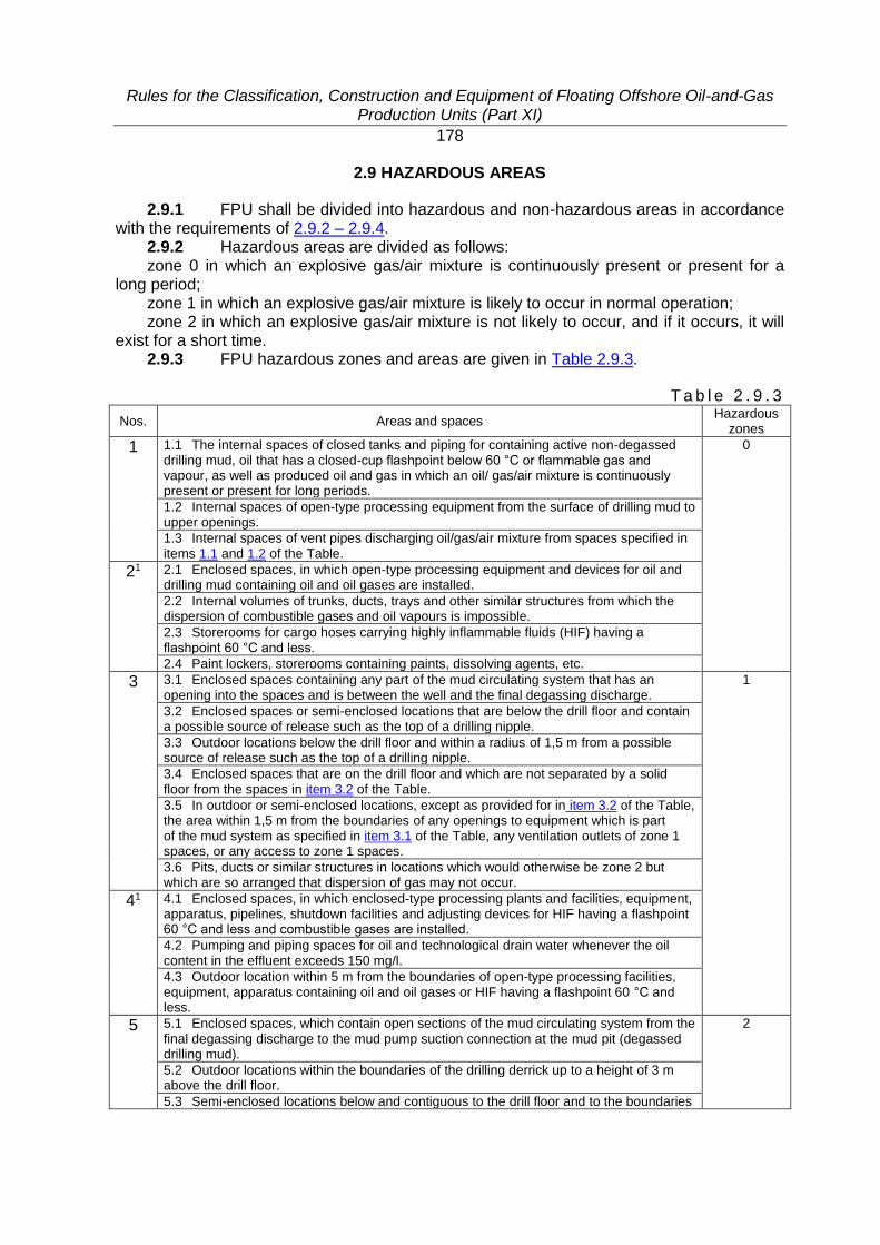
Rules for the Classification, Construction and Equipment of Floating Offshore Oil-and-Gas Production Units (Part XI)
178
2.9 HAZARDOUS AREAS
2.9.1 FPU shall be divided into hazardous and non-hazardous areas in accordance with the requirements of 2.9.2 – 2.9.4.
2.9.2 Hazardous areas are divided as follows: zone 0 in which an explosive gas/air mixture is continuously present or present for a
long period; zone 1 in which an explosive gas/air mixture is likely to occur in normal operation; zone 2 in which an explosive gas/air mixture is not likely to occur, and if it occurs, it will
exist for a short time. 2.9.3 FPU hazardous zones and areas are given in Table 2.9.3.
T a b l e 2 . 9 . 3
Nos. Areas and spaces Hazardous
zones
1 1.1 The internal spaces of closed tanks and piping for containing active non-degassed drilling mud, oil that has a closed-cup flashpoint below 60 °C or flammable gas and vapour, as well as produced oil and gas in which an oil/ gas/air mixture is continuously present or present for long periods.
0
1.2 Internal spaces of open-type processing equipment from the surface of drilling mud to upper openings.
1.3 Internal spaces of vent pipes discharging oil/gas/air mixture from spaces specified in items 1.1 and 1.2 of the Table.
21 2.1 Enclosed spaces, in which open-type processing equipment and devices for oil and drilling mud containing oil and oil gases are installed.
2.2 Internal volumes of trunks, ducts, trays and other similar structures from which the dispersion of combustible gases and oil vapours is impossible.
2.3 Storerooms for cargo hoses carrying highly inflammable fluids (HIF) having a flashpoint 60 °C and less.
2.4 Paint lockers, storerooms containing paints, dissolving agents, etc.
3 3.1 Enclosed spaces containing any part of the mud circulating system that has an opening into the spaces and is between the well and the final degassing discharge.
1
3.2 Enclosed spaces or semi-enclosed locations that are below the drill floor and contain a possible source of release such as the top of a drilling nipple.
3.3 Outdoor locations below the drill floor and within a radius of 1,5 m from a possible source of release such as the top of a drilling nipple.
3.4 Enclosed spaces that are on the drill floor and which are not separated by a solid floor from the spaces in item 3.2 of the Table.
3.5 In outdoor or semi-enclosed locations, except as provided for in item 3.2 of the Table, the area within 1,5 m from the boundaries of any openings to equipment which is part of the mud system as specified in item 3.1 of the Table, any ventilation outlets of zone 1 spaces, or any access to zone 1 spaces.
3.6 Pits, ducts or similar structures in locations which would otherwise be zone 2 but which are so arranged that dispersion of gas may not occur.
41 4.1 Enclosed spaces, in which enclosed-type processing plants and facilities, equipment, apparatus, pipelines, shutdown facilities and adjusting devices for HIF having a flashpoint 60 °C and less and combustible gases are installed.
4.2 Pumping and piping spaces for oil and technological drain water whenever the oil content in the effluent exceeds 150 mg/l.
4.3 Outdoor location within 5 m from the boundaries of open-type processing facilities, equipment, apparatus containing oil and oil gases or HIF having a flashpoint 60 °C and less.
5 5.1 Enclosed spaces, which contain open sections of the mud circulating system from the final degassing discharge to the mud pump suction connection at the mud pit (degassed drilling mud).
2
5.2 Outdoor locations within the boundaries of the drilling derrick up to a height of 3 m above the drill floor.
5.3 Semi-enclosed locations below and contiguous to the drill floor and to the boundaries

Rules for the Classification, Construction and Equipment of Floating Offshore Oil-and-Gas Production Units (Part XI)
179
Nos. Areas and spaces Hazardous
zones
of the derrick or to the extent of any enclosure which is liable to trap gases.
5.4 In outdoor locations below the drill floor, within a radius of 1,5 m area beyond the zone 1 area as specified in item 3.3 of the Table.
5.5 The areas 1,5 m beyond the zone 1 areas specified in 3.5 of the Table and beyond the semi-enclosed locations specified in item 3.2 of the Table.
5.6 Outdoor areas within 1,5 m of the boundaries of any ventilation outlet from or access to a zone 2 space (from non-hazardous space).
5.7 Semi-enclosed derricks to the extent of their enclosure above the drill floor or to a height of 3 m above the drill floor, whichever is greater.
5.8 Air-closed spaces (locks) between zone 1 and the non-hazardous areas.
6 6.1 Outdoor location within 3 m from the boundaries of enclosed-type processing facilities, equipment, apparatus, as well as from the boundaries of Christmas trees.
6.2 Semi-enclosed spaces, in which processing facilities, arrangements, equipment, apparatus are installed; spaces within a radius of 15 m about the well axis from lower structures of the platform to the full height of the drilling derrick.
6.3 Semi-enclosed spaces below the drilling derrick working floor within the boundaries of enclosure containing oil and oil gases or HIF having a flashpoint 60 °C and less.
6.4 Semi-enclosed spaces, in which Christmas trees are installed within the boundaries of enclosure.
6.5 Semi-enclosed spaces for storage of cargo hoses carrying HIF having a flashpoint 60 °C and less.
6.6 The spaces extended in horizontal and vertical directions within 3 m from the boundaries from air pipes and safety valves and devices for air ejection from exhaust ventilation systems of zone 1 and 2 spaces.
6.7 The spaces extended in horizontal and vertical directions within 0,5 m from the boundaries from any holes and openings (windows, doors) of zone 1 and 2 spaces.
1 The areas and spaces specified in items 2, 4 and 6 of the Table form part of hazardous zones only under condition of FPU/MODU/FOP compliance with the requirements of the RF supervisory bodies.
2.9.4 Other locations and spaces not associated with zones 0, 1 and 2 relate to
non-hazardous area. 2.9.5 Hazardous zones classification for locations and spaces in accordance with
Table 2.9.3 (items 1, 3 and 5) may, in each particular case, be changed on the Register requirement depending on the structural features of the unit and the conditions of locations and spaces ventilation.

Rules for the Classification, Construction and Equipment of Floating Offshore Oil-and-Gas Production Units (Part XI)
180
2.10 OPENINGS. ACCESS AND VENTILATION CONDITIONS AFFECTING THE EXTENT OF HAZARDOUS AREAS
2.10.1 Openings and ventilation of hazardous zones shall meet the requirements of 2.10, Part X "Electrical Equipment" of the MODU/FOP Rules.
Rules for the Classification, Construction and Equipment of Floating Offshore Oil-and-Gas Production Units (Part XI)
181
2.11 ELECTRICAL EQUIPMENT AND CABLES IN HAZARDOUS AREAS
2.11.1 Electrical equipment and cables in hazardous areas shall meet the requirements of 2.11, Part X "Electrical Equipment" of the MODU/FOP Rules, as well as the applicable requirements of 19.2, Part XI "Electrical Equipment" of the RS Rules, in particular:
regarding electrical equipment – 19.2.4.1, 19.2.4.2, 19.2.4.4 – 19.2.4.12; regarding cable laying – 19.2.6; regarding integrated cargo and ballast systems – 19.2.7.

Rules for the Classification, Construction and Equipment of Floating Offshore Oil-and-Gas Production Units (Part XI)
182
2.12 ANTISTATIC EARTHING
2.12.1 Antistatic earthing shall meet the requirements of 2.12, Part X "Electrical Equipment" of the MODU/FOP Rules.

Rules for the Classification, Construction and Equipment of Floating Offshore Oil-and-Gas Production Units (Part XI)
183
3 MAIN SOURCE OF ELECTRICAL POWER
3.1 COMPOSITION AND CAPACITY OF MAIN SOURCE OF ELECTRICAL POWER
3.1.1 Composition and capacity of main source of electrical power shall meet the requirements of 3.1, Part X "Electrical Equipment" of the MODU/FOP Rules.
3.1.2 FPU main source might consist of two independent feeders from external power sources laid in different cable runs spaced as far as possible.
3.1.3 Composition and capacity of electrical units of the main source or feeders from external power sources shall be determined with regard to the following modes of the FPU operation:
.1 operation at sea and/or maneuvering;
.2 production and treatment of products;
.3 inboard/outboard transfer of products including preparatory and completion operations;
.4 emergency modes, for instance, fire, flooding or others emergency conditions affecting the FPU safety;
.5 other modes in compliance with arrangement and purpose of FPU, for example: living quarter operation (for manned SPM), taking-in of fuels and supply, routine maintenance.

Rules for the Classification, Construction and Equipment of Floating Offshore Oil-and-Gas Production Units (Part XI)
184
3.2 GENERATING SETS
3.2.1 Generating sets shall meet the requirements of 3.2, Part X "Electrical Equipment" of the MODU/FOP Rules.
Rules for the Classification, Construction and Equipment of Floating Offshore Oil-and-Gas Production Units (Part XI)
185
3.3 NUMBER AND CAPACITY OF TRANSFORMERS
3.3.1 Number and capacity of transformers shall meet the requirements of 3.3, Part X "Electrical Equipment" of the MODU/FOP Rules.
Rules for the Classification, Construction and Equipment of Floating Offshore Oil-and-Gas Production Units (Part XI)
186
3.4 POWER SUPPLY FROM AN EXTERNAL SOURCE OF ELECTRICAL POWER
3.4.1 Power supply from external source of electrical power shall meet the requirements of 3.4, Part X "Electrical Equipment" of the MODU/FOP Rules.

Rules for the Classification, Construction and Equipment of Floating Offshore Oil-and-Gas Production Units (Part XI)
187
3.5 CONNECTION OF UNITS OF MAIN SOURCE OF ELECTRICAL POWER
3.5.1 Connection of units of main source of electrical power shall meet the requirements of 3.5, Part X "Electrical Equipment" of the MODU/FOP Rules.
Rules for the Classification, Construction and Equipment of Floating Offshore Oil-and-Gas Production Units (Part XI)
188
3.6 UNINTERRUPTIBLE POWER SUPPLIES
3.6.1 Uninterruptible power supplies (UPS) shall meet the requirements of 3.6, Part X "Electrical Equipment" of the MODU/FOP Rules.

Rules for the Classification, Construction and Equipment of Floating Offshore Oil-and-Gas Production Units (Part XI)
189
4 DISTRIBUTION OF ELECTRICAL POWER
4.1 Distribution of electrical power shall meet the requirements of Section 4, Part X "Electrical Equipment" of the MODU/FOP Rules.
Rules for the Classification, Construction and Equipment of Floating Offshore Oil-and-Gas Production Units (Part XI)
190
5 ELECTRIC DRIVES OF MACHINERY AND ARRANGEMENTS
5.1 Electric drives of machinery and arrangements shall meet the requirements of Section 5, Part X "Electrical Equipment" of the MODU/FOP Rules.

Rules for the Classification, Construction and Equipment of Floating Offshore Oil-and-Gas Production Units (Part XI)
191
6 LIGHTING
6.1 Lighting shall meet the requirements of Section 6, Part Х "Electrical Equipment" of the MODU/ FOP Rules, taking into consideration of the following amendment.
6.2 Escape lighting shall meet the requirements of Part XVI "General Requirements and Safety Principles" and shall be provided at the escape routes, as well as in the staff muster stations.
Rules for the Classification, Construction and Equipment of Floating Offshore Oil-and-Gas Production Units (Part XI)
192
7 INTERNAL COMMUNICATION AND ALARMS
7.1 Internal communication and alarms shall meet the requirements of Section 7, Part Х "Electrical Equipment" of the MODU/FOP Rules.
Rules for the Classification, Construction and Equipment of Floating Offshore Oil-and-Gas Production Units (Part XI)
193
8 ELECTRIC PROTECTION SYSTEM
8.1 Electric protection system shall meet the requirements of Section 8, Part Х "Electrical Equipment" of the MODU/FOP Rules.
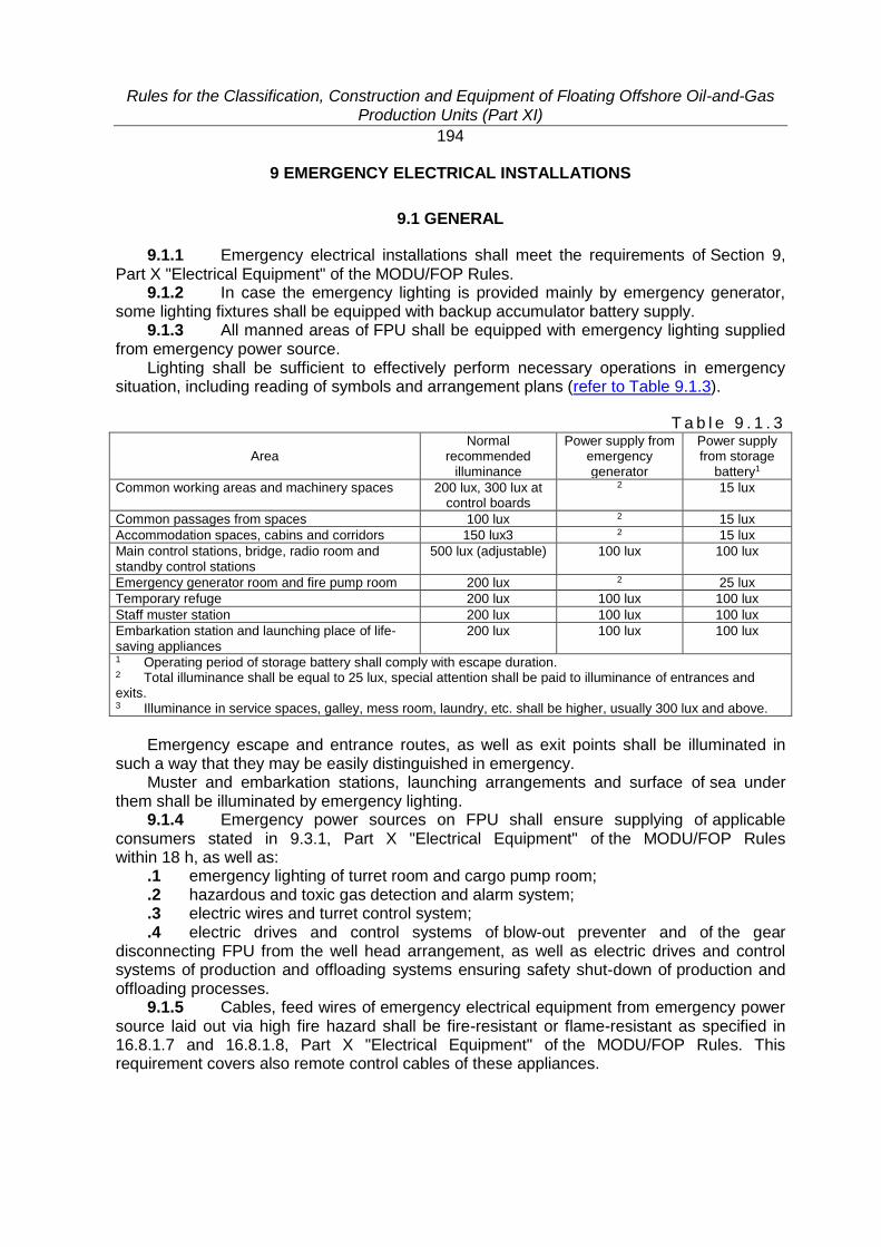
Rules for the Classification, Construction and Equipment of Floating Offshore Oil-and-Gas Production Units (Part XI)
194
9 EMERGENCY ELECTRICAL INSTALLATIONS
9.1 GENERAL
9.1.1 Emergency electrical installations shall meet the requirements of Section 9, Part X "Electrical Equipment" of the MODU/FOP Rules.
9.1.2 In case the emergency lighting is provided mainly by emergency generator, some lighting fixtures shall be equipped with backup accumulator battery supply.
9.1.3 All manned areas of FPU shall be equipped with emergency lighting supplied from emergency power source.
Lighting shall be sufficient to effectively perform necessary operations in emergency situation, including reading of symbols and arrangement plans (refer to Table 9.1.3).
T a b l e 9 . 1 . 3
Area Normal
recommended illuminance
Power supply from emergency generator
Power supply from storage
battery1
Common working areas and machinery spaces 200 lux, 300 lux at control boards
2 15 lux
Common passages from spaces 100 lux 2 15 lux
Accommodation spaces, cabins and corridors 150 lux3 2 15 lux
Main control stations, bridge, radio room and standby control stations
500 lux (adjustable) 100 lux 100 lux
Emergency generator room and fire pump room 200 lux 2 25 lux
Temporary refuge 200 lux 100 lux 100 lux
Staff muster station 200 lux 100 lux 100 lux
Embarkation station and launching place of life-saving appliances
200 lux 100 lux 100 lux
1 Operating period of storage battery shall comply with escape duration. 2 Total illuminance shall be equal to 25 lux, special attention shall be paid to illuminance of entrances and exits. 3 Illuminance in service spaces, galley, mess room, laundry, etc. shall be higher, usually 300 lux and above.
Emergency escape and entrance routes, as well as exit points shall be illuminated in
such a way that they may be easily distinguished in emergency. Muster and embarkation stations, launching arrangements and surface of sea under
them shall be illuminated by emergency lighting. 9.1.4 Emergency power sources on FPU shall ensure supplying of applicable
consumers stated in 9.3.1, Part X "Electrical Equipment" of the MODU/FOP Rules within 18 h, as well as:
.1 emergency lighting of turret room and cargo pump room;
.2 hazardous and toxic gas detection and alarm system;
.3 electric wires and turret control system;
.4 electric drives and control systems of blow-out preventer and of the gear disconnecting FPU from the well head arrangement, as well as electric drives and control systems of production and offloading systems ensuring safety shut-down of production and offloading processes.
9.1.5 Cables, feed wires of emergency electrical equipment from emergency power source laid out via high fire hazard shall be fire-resistant or flame-resistant as specified in 16.8.1.7 and 16.8.1.8, Part X "Electrical Equipment" of the MODU/FOP Rules. This requirement covers also remote control cables of these appliances.

Rules for the Classification, Construction and Equipment of Floating Offshore Oil-and-Gas Production Units (Part XI)
195
9.1.6 Systems for tackling emergencies, emergency power supply as well as control and monitoring systems associated with them shall be self-contained and located in such a way that they are not damaged due to the causes affecting the main power supply system.
Rules for the Classification, Construction and Equipment of Floating Offshore Oil-and-Gas Production Units (Part XI)
196
9.2 EMERGENCY SHUTDOWN AND SAFETY SYSTEMS
9.2.1 FPU shall be provided with an emergency shutdown system (ESD) and process equipment control and safety system (ECS). The ESD and ECS systems may be combined in one system.
9.2.2 The objective of an emergency shutdown system (ESD) is initiating actions to shut down and isolate electrical and processing equipment in order to prevent escalation of abnormal conditions into a major hazardous event and to limit the extent and duration of any such events which do occur.
9.2.3 The main objective of ECS is to shutdown the equipment for production, storage and offloading hydrocarbons, as well as to relieve overpressure by means of specially provided systems to prevent hazard for the whole installation protection of FPU, its personnel and equipment in emergency situations and to prevent the environmental pollution in case of equipment breakage or process failure.
9.2.4 Emergency shutdown (ESD) system. 9.2.4.1 Emergency shutdown (ESD) system shall comply with the following functional
requirements: isolate FPU from the major product inventories within pipelines and reservoirs which, if
released on failure, would pose an intolerable risk to the personnel, environment and equipment;
sectionalize topside inventory to limit the quantity of material released on loss of containment;
monitor potential ignition sources such as fired units, engines and non-essential electrical equipment;
control subsurface safety valve(s) on FPU; where appropriate, depressurize product inventory and vent it to a safe place. 9.2.4.2 ESD system shall be designed so that: it shall provide all necessary information at the control station so that the operator could
manage the emergency situation; it may be initiated manually or automatically or both. When manual initiation is required,
the ESD system shall not require the operators to make complex or non-routine decisions; once initiated, all control actions required by ESD system shall occur automatically; manual stations for initiation of ESD shall be located in easily accessible, well marked
positions protected against unintentional activation; it shall contain facilities for testing of both input/output devices and internal functions; the reliability of the system is provided by redundancy of its elements; the system contains means of automatic self-control of the operational condition of its
elements and provides alarm signals to the FPU personnel if an element is faulty; the system maintains its operability under possible fire conditions within the period
of time sufficient for restoring the process equipment safe condition. 9.2.4.3 ESD system shall provide 3 levels of emergency shutdown (the first level is
the highest), which are selected based on the necessity of preventing the emergency situation escalation from one zone of FPU to another:
1st level – emergency shutdown initiated automatically during the fire or major product spill. The personnel evacuation from FPU may become necessary. The 1st level emergency shutdown may also be initiated manually;
2nd level – process shutdown initiated automatically in case of significant deviation of process parameters on FPU from maximum allowable values or as a result of initiating the 1st or 2nd level of emergency shutdown, e.g., the emergency shutdown of a shore reservoir;
3rd level – local shutdown initiated by switching off of specific types of equipment.
Rules for the Classification, Construction and Equipment of Floating Offshore Oil-and-Gas Production Units (Part XI)
197
9.2.4.4 Upon the emergency shutdown the following explosion proof electrical equipment located in non-enclosed spaces and certified for operation within zone 2 shall continue functioning:
.1 emergency lighting within 30 min;
.2 preventer emergency control system;
.3 general alarm system;
.4 public address system;
.5 communication radio equipment supplied from its own accumulator batteries; 9.2.4.5 All ESD levels shall be initiated automatically (on receiving fire protection
system signals) or manually from CCS. 9.2.4.6 Manual initiating of each ESD level shall be performed by pushing one button.
The time required for the process control systems to activate each ESD level after the latter has been initiated by the operator shall be reduced to minimum.
9.2.4.7 ESD system shall be arranged so that the highest level shutdown initiation provides for automatic activation of all the lower levels shutdown operations.
9.2.4.8 Protection shall be provided against the ESD activations caused by accidental or short-time signals of process disruption, including switching over from/to reserve or emergency power supply.
9.2.4.9 In case of complete power, compressed air or hydraulic supply failure the way for restoring safe condition of the process equipment shall be provided.
9.2.4.10 Taking into consideration exceptional circumstances under which the danger of explosion can spread onto hazardous areas, special means shall be provided for effecting selective manual disconnection or shutdown of:
ventilation; all non-essential electrical equipment in non-hazardous areas; all essential electrical equipment including the equipment supplied from accumulators
and generator prime movers, except such previously tested equipment as emergency lighting, general alarm system, etc., which shall function in case of emergency.
The radio installation supplied from accumulator batteries is not required to be previously tested or incorporated into ESD system.
9.2.4.11 Technical devices for ESD systems manual activation shall be located in the following rooms:
emergency control stations; auxiliary control stations, e.g., main escape routes, helideck, etc. 9.2.4.12 The valve activated automatic shutdown shall take place under the following
conditions: discovered fire in turret and crude oil tanks areas; discovered product vapour concentration is 50 % of LFL in turret and cargo tank areas. 9.2.4.13 The automatically activated ventilation shutdown shall be performed under the
following conditions: discovered maximum gas concentration is 20 % of LFL in air inlets in the non-hazardous
areas; discovered fire in the enclosed non-hazardous area. 9.2.4.14 ESD system shall be based on open valve and equipment circuits. Electric ESD systems shall be designed so that the risk of unforeseen shutdown due to
a failure in the functioning of the system or of unforeseen shutdown operation is minimized. 9.2.4.15 ESD initiation shall activate audible and visual alarm signals at the control
stations. The alarm signals shall be indicated so that the equipment initiating the ESD activation
and its location can be easily identified at the control stations.
Rules for the Classification, Construction and Equipment of Floating Offshore Oil-and-Gas Production Units (Part XI)
198
9.2.4.16 ESD system activating sensors, actuators/triggers and the equipment and circuits associated with them shall be installed and operate independently of monitoring and control systems.
9.2.4.17 Manual ESD actuation system shall be, as far as practicable, independent of the automatic ESD actuation system.
9.2.4.18 ESD system shall be designed so that it can be tested when FPU is in operation.
9.2.5 Equipment safety and control system (ECS) in the FPU process area. 9.2.5.1 ECS system is intended to shutdown the equipment for production, treatment,
storage and offloading hydrocarbons, as well as to relieve overpressure by means of specially provided systems to prevent hazard to the whole FPU.
9.2.5.2 ECS design shall be developed in accordance with the FPU design, set of equipment installed and production process peculiarities. Requirements of Part XIV "Automation" of the MODU/FOP Rules shall be considered as applicable.
9.2.5.3 ECS shall function automatically and independently of other control and monitoring systems. ECS manual activation shall be provided as follows: from the control station, wellhead areas (well cutoff valves), helideck and embarkation stations. The possibility of ECS remote activation shall be provided.
9.2.5.4 ECS activation periodic checks shall be provided by simulating emergency situations specified in ECS design.
9.2.5.5 The requirements of this chapter apply to ECS equipment subject to technical supervision by the Register irrespective of an automation mark in the FPU class notation.
9.2.5.6 Depending on possible consequences of emergency situation, the following process shutdown shall be provided by ECS:
shutdown of separate FPU blocks and systems both with and without emptying them of the product and stopping the entire process;
complete shutdown of the hydrocarbon production and treatment of other systems both with and without emptying them of the product;
complete shutdown of all process equipment (except emergency life support systems), closing cutoff valves on the wellheads and pipelines connecting FPU with the other structures of the offshore oil and gas field facilities or with transport ships, emptying the process equipment and pipelines through the systems provided for this purpose.
9.2.5.7 In case of emergency situation in one of the wells or one of the equipment blocks the possibility of their shutdown shall be provided (i.e. partial shutdown of the process).
ECS shall provide the following compulsory stages of partial shutdown: closing of all wellhead valves and plates (including those fitted in the block
of submerged blowout preventer equipment); complete shutdown of the production and treatment block and equipment and systems
associated with it. The number of stages depends on the particular FPU design. 9.2.5.8 The algorithm of closing/opening cutoff valves, switching on/off other devices,
the list of possible process failures and troubleshooting, list of parameters values which are characteristic to partial or complete process stopping shall be specified in the corresponding sections of the equipment operating manuals.
9.2.5.9 All process shutdown operations shall be performed automatically upon the command given by the process control system.
In case of automatic control system failure the possibility for operator's intervention shall be provided and the work shall proceed manually.
9.2.5.10 The process shall be terminated in case of fire in the process area.
Rules for the Classification, Construction and Equipment of Floating Offshore Oil-and-Gas Production Units (Part XI)
199
9.2.5.11 When the product vapour concentration in the air of the hazardous zones (0, 1, 2) reaches 20 % of LEL (lower flame limit) alarm actuation shall be provided and emergency exhaust ventilation (EEV) shall be activated.
9.2.5.12 In case of further concentration increase up to 50 % of LEL, blackout, fire, and high/low pressure in the wellhead product delivery pipeline, all the processes in the oil and gas production systems shall be shutdown, including EEV.
9.2.5.13 Realization of algorithms of emergency shutdown of hydrocarbon production process of products in any module or block shall not lead to an emergency situation on other FPU modules or blocks.
9.2.5.14 The complete shutdown of all process equipment and processes upon the operator's signal from the CCS or other control stations is provided in case of the emergency situation escalation: oil/gas blowout; seal failure of the systems containing products; fire alarm actuation.
9.2.5.15 In case of complete process equipment and processes shutdown the following shall be provided:
closing of wellhead valves; product treatment process shutdown; disconnection of main sources of electric power; 9.2.5.16 The signal for automatic operation of closing devices (cutoff valves) shall be
provided in response to: the signal from air monitoring sensors; fire alarm actuation; loss of power supply; safety systems failures; ship contact with FPU when mooring; installation loss of stability; structures collapse due to the helicopter crash and fall onto the topside. 9.2.5.17 Response to above mentioned signals shall also be provided manually upon
the signal from the control panel or by pressing emergency stop buttons located in other FPU areas.
9.2.5.18 Provision shall be made for the possibility of remote control of all the steps of shutdown process.

Rules for the Classification, Construction and Equipment of Floating Offshore Oil-and-Gas Production Units (Part XI)
200
10 ELECTRICAL MACHINES
10.1 Electrical machines shall meet the requirements of Section 10, Part Х "Electrical Equipment" of the MODU/FOP Rules.

Rules for the Classification, Construction and Equipment of Floating Offshore Oil-and-Gas Production Units (Part XI)
201
11 TRANSFORMERS
11.1 Transformers shall meet the requirements of Section 11, Part Х "Electrical Equipment" of the MODU/FOP Rules.

Rules for the Classification, Construction and Equipment of Floating Offshore Oil-and-Gas Production Units (Part XI)
202
12 POWER SEMICONDUCTOR UNITS
12.1 Power semiconductor units shall meet the requirements of Section 12, Part Х "Electrical Equipment" of the MODU/FOP Rules.

Rules for the Classification, Construction and Equipment of Floating Offshore Oil-and-Gas Production Units (Part XI)
203
13 ACCUMULATOR BATTERIES
13.1 Accumulator batteries shall meet the requirements of Section 13, Part Х "Electrical Equipment" of the MODU/FOP Rules.

Rules for the Classification, Construction and Equipment of Floating Offshore Oil-and-Gas Production Units (Part XI)
204
14 ELECTRICAL APPARATUS AND ACCESSORIES
14.1 Electrical apparatus and accessories shall meet the requirements of Section 14, Part Х "Electrical Equipment" of the MODU/FOP Rules.

Rules for the Classification, Construction and Equipment of Floating Offshore Oil-and-Gas Production Units (Part XI)
205
15 ELECTRICAL COOKING AND HEATING APPLIANCES
15.1 Electrical cooking and heating appliances shall meet the requirements of Section 15, Part Х "Electrical Equipment" of the MODU/FOP Rules.

Rules for the Classification, Construction and Equipment of Floating Offshore Oil-and-Gas Production Units (Part XI)
206
16 CABLES AND WIRES
16.1 Cables and wires shall meet the requirements of Section 16, Part Х "Electrical Equipment" of the MODU/FOP Rules.

Rules for the Classification, Construction and Equipment of Floating Offshore Oil-and-Gas Production Units (Part XI)
207
17 ELECTRIC PROPULSION PLANTS
17.1 Electric propulsion plants shall meet the requirements of Section 17, Part Х "Electrical Equipment" of the MODU/FOP Rules.
Rules for the Classification, Construction and Equipment of Floating Offshore Oil-and-Gas Production Units (Part XI)
208
18 REQUIREMENTS FOR ELECTRICAL EQUIPMENT DESIGNED FOR VOLTAGE ABOVE 1000 V UP TO 15 KV
18.1 Electrical equipment designed for voltage above 1000 V up to 15 kV shall
meet the requirements of Section 18, Part Х "Electrical Equipment" of the MODU/FOP Rules.

Rules for the Classification, Construction and Equipment of Floating Offshore Oil-and-Gas Production Units (Part XI)
209
19 SPARE PARTS
19.1 Spare parts shall meet the requirements of Section 19, Part Х "Electrical Equipment" of the MODU/FOP Rules.

Rules for the Classification, Construction and Equipment of Floating Offshore Oil-and-Gas Production Units (Part XII)
210
PART XII. REFRIGERATING PLANTS
1 GENERAL
1.1 The refrigerating plants installed stationary on FPU shall meet the requirements of Sections 1 – 8, 11 and 12, Part XII "Refrigerating Plants" of the RS Rules.

Rules for the Classification, Construction and Equipment of Floating Offshore Oil-and-Gas Production Units (Part XIII)
211
PART XIII. MATERIALS
1 GENERAL
1.1 Materials and products used during FPU construction and outfitting shall meet the requirements of Part XIII "Materials" of the RS Rules, Part XII "Materials" of the MODU/FOP Rules, as well as Part IX "Materials and Welding" of the Rules for the Classification and Construction of Gas Carriers, whichever is applicable.
Rules for the Classification, Construction and Equipment of Floating Offshore Oil-and-Gas Production Units (Part XIV)
212
PART XIV. WELDING
1 GENERAL
1.1 Requirements of the present Part apply to welding of the FPU hull structures, machinery and machinery installations, steam boilers, heat exchangers, pressure vessels, piping, equipment and arrangements.
1.2 Welded joints and structures subject to the Register technical supervision shall meet the requirements of Part XIV "Welding" of the RS Rules and Part XIII "Welding" of the MODU/FOP Rules.
1.3 As far as structures stated in 1.1 are concerned, the following is subject to the Register technical supervision:
.1 welding consumables;
.2 welding procedures (selection of welding consumables, preparation of components for welding, assembly, pre- and postheating, heat treatment);
.3 methods and scope of inspection, criteria for evaluation of welded joints. 1.4 The scope of technical documentation on welding, which shall be agreed as
part of the FPU design is set out in Part I "Classification" of the RS Rules. Technical documentation on items specified in 1.1 shall include information on welding required by those parts of the RS Rules, which cover the items concerned.
1.5 Welding of items stated in 1.1 shall be effected by certified welders (operators) and Register-approved welding works (shops, bays) using welding consumables and welding procedures approved by the Register.
1.6 To effect welding operations and non-destructive testing of welded joints in structures subject to the Register technical supervision the works shall have adequate equipment.
1.7 Where welding is performed at low temperatures working conditions shall be provided to enable the welder to produce sound welds. The welding site shall be protected from draught and precipitation. When welding is performed at low temperature, the weld, if necessary, shall be protected from excessively rapid cooling.
1.8 On condition proper quality of welded joints is ensured, welding operations on structures specified in 1.1 of hull structural steel of normal and higher strength 20 mm or below in thickness are permitted at ambient temperature –25 °С, provided the welding consumables have been tested at this temperature according to the Register-approved procedure.
1.9 The welding of piping made of low alloy steel, piping of the steam main as well as piping, which shall operate at temperatures above 350 °С shall not be conducted at temperatures below zero.
1.10 The edge preparation of the parts to be welded shall be effected by methods which ensure the required quality of welded joints.
1.11 From the edges of the parts to be welded, oil, moisture, scale, rust and other contaminating substances shall be removed.
1.12 When welding of structures is effected at temperatures below zero the edges being welded shall be free from snow, hoar-frost and ice and be dry.
1.13 When structures are welded, the sequence of welding operations shall be such as to ensure the absence of excessive residual stresses or distortions.
1.14 Inspection of welding operations and welded joints during manufacture of structures and components shall be performed by the inspection authorities of the works. The results of the inspection shall be registered according to the procedure adopted at

Rules for the Classification, Construction and Equipment of Floating Offshore Oil-and-Gas Production Units (Part XIV)
213
works, field not less than 5 years after the FPU commissioning and submitted to the surveyor to the Register at his request for examination.
1.15 The non-destructive testing of welded joints shall be effected according to the Register-approved standards or procedures and by laboratories recognized by the Register.
Rules for the Classification, Construction and Equipment of Floating Offshore Oil-and-Gas Production Units (Part XV)
214
PART XV. AUTOMATION
1 GENERAL
1.1 APPLICATION
1.1.1 Requirements of Sections 1 – 5, 8 and 9 apply to the automation equipment liable to technical supervision without regard to the automation mark in the class notation of FPU.
1.1.2 Requirements of Sections 6 and 7 additionally apply to the equipment of FPU, which class notation is added with one of the automation marks and/or one of the dynamic positioning system marks in accordance with Part I "Classification".
1.1.3 Requirements of Section 6 also apply to FPU without the automation mark in the class notation but those equipped with the central control station and remote control systems for the machinery and arrangements.
1.1.4 The present part of the Rules contains technical requirements for the automation equipment and FPU where it is installed as well as it contains the minimum scope of the remote, automated and automatic control, protection, alarm and indication systems.
Rules for the Classification, Construction and Equipment of Floating Offshore Oil-and-Gas Production Units (Part XV)
215
1.2 DEFINITIONS AND EXPLANATIONS
1.2.1 Definitions and explanations are given in the General Regulations for the Classification and Other Activity, Part I "Classification" and Part XV "Automation" of the RS Rules, Part I "Classification" and XIV "Automation" of the MODU/FOP Rules, as well as in Part I "Classification", Part III "Equipment, Arrangements and Outfit" and Part VI "Fire and Explosion Protection" of the FPU Rules.
1.2.2 Thruster assisted position mooring system is a position mooring system where an auxiliary dynamic positioning system is used to supplement a position mooring system.
Rules for the Classification, Construction and Equipment of Floating Offshore Oil-and-Gas Production Units (Part XV)
216
1.3 SCOPE OF TECHNICAL SUPERVISION
1.3.1 Automation components, control devices and systems listed in 1.3.2, Part XIV "Automation" of the MODU/FOP Rules in the applicable scope are liable to the technical supervision of the design and manufacture of equipment and its details.
Rules for the Classification, Construction and Equipment of Floating Offshore Oil-and-Gas Production Units (Part XV)
217
1.4 TECHNICAL DOCUMENTATION
1.4.1 Technical documentation in accordance with the requirements of 1.4, Part XV "Automation" of the RS Rules and 1.4, Part XIV "Automation" of the MODU/FOP Rules shall be submitted to the Register in respect of the automation equipment listed in 1.3.1.
Rules for the Classification, Construction and Equipment of Floating Offshore Oil-and-Gas Production Units (Part XV)
218
2 DESIGN OF AUTOMATION SYSTEMS, AUTOMATION COMPONENTS AND CONTROL DEVICES
2.1 GENERAL
2.1.1 Automation systems shall comply with the requirements of 2.1, Part XIV "Automation" of the MODU/FOP Rules.
2.1.2 Automation components, devices and systems fitted on open decks shall operate without fails at a design external temperature appropriate to the FPU area of operation.

Rules for the Classification, Construction and Equipment of Floating Offshore Oil-and-Gas Production Units (Part XV)
219
2.2 REQUIREMENTS FOR COMPONENTS, DEVICES AND SYSTEMS OF THE AUTOMATED CONTROL, ALARM, PROTECTION, INDICATION AND LOGGING
2.2.1 Components, devices and systems of the automated control, alarm, protection, indication and logging shall comply with the requirements of 2.2 – 2.4, Part XIV "Automation" of the MODU/FOP Rules correspondingly.
Rules for the Classification, Construction and Equipment of Floating Offshore Oil-and-Gas Production Units (Part XV)
220
3 POWER SUPPLY OF AUTOMATION SYSTEMS
3.1 Power supply of the automation system shall comply with the requirements of Section 3, Part XIV "Automation" of the MODU/FOP Rules.
Rules for the Classification, Construction and Equipment of Floating Offshore Oil-and-Gas Production Units (Part XV)
221
4 AUTOMATED MACHINERY AND INSTALLATIONS
4.1 Automated machinery and installations shall comply with the requirements of Section 4, Part XIV "Automation" of the MODU/FOP Rules.

Rules for the Classification, Construction and Equipment of Floating Offshore Oil-and-Gas Production Units (Part XV)
222
5 COMPUTERS AND COMPUTER-BASED AUTOMATION SYSTEMS
5.1 Computers and computer-based automation systems shall comply with the requirements of Section 5, Part XIV "Automation" of the MODU/FOP Rules.

Rules for the Classification, Construction and Equipment of Floating Offshore Oil-and-Gas Production Units (Part XV)
223
6 OBJECTS WITH THE AUT MARK IN THE CLASS NOTATION
6.1 Objects with the AUT mark in the class notation shall comply with the requirements of Section 6, Part XIV "Automation" of the MODU/FOP Rules.

Rules for the Classification, Construction and Equipment of Floating Offshore Oil-and-Gas Production Units (Part XV)
224
7 DYNAMIC POSITIONING SYSTEMS
7.1 Dynamic positioning systems shall comply with the requirements of Section 7, Part XIV "Automation" of the MODU/FOP Rules.

Rules for the Classification, Construction and Equipment of Floating Offshore Oil-and-Gas Production Units (Part XV)
225
8 POSITION MOORING SYSTEM
8.1 Position mooring system shall comply with the requirements of 8.1 and 8.2, Part XIV "Automation" of the MODU/FOP Rules.

Rules for the Classification, Construction and Equipment of Floating Offshore Oil-and-Gas Production Units (Part XV)
226
9 THRUSTER ASSISTED POSITION MOORING SYSTEM
9.1 Applicable requirements of 7.7, 7.8, 7.12 and 8.2, Part XIV "Automation" of the MODU/FOP Rules apply to the control systems of the thruster assisted position mooring system.
Rules for the Classification, Construction and Equipment of Floating Offshore Oil-and-Gas Production Units (Part XVI)
227
PART XVI. GENERAL REQUIREMENTS AND SAFETY PRINCIPLES
1 GENERAL
1.1 FPU safety shall comply with the requirements of Part XV "MODU and FOP Safety Assessment" of the MODU/FOP Rules, as well as with the requirements set forth below.
1.2 Safety and location of equipment, machinery and arrangements providing FPU operation shall meet the requirements of the RS Rules to the extent that they are practicable and reasonable, unless otherwise specified.
1.3 Structural, technical and organizational measures shall be taken to ensure the FPU safety.
1.4 The basic principle for the FPU safety is the separation of functional areas (zones) of the unit (accommodation, storage, processing areas etc.) in accordance with their explosion hazard potential. Zones of high risk potential (hazardous zones) shall be separated from the others.
Hazardous zones are enclosed spaces, semi-enclosed and out-door locations and spaces in which, due to presence of explosive gas or explosive gas/air mixture, explosion hazard exists continuously or periodically.
Other zones and areas are considered to be non-hazardous. 1.5 Classification of the FPU hazardous zones shall comply with the requirements
of 19.2.3, Part XI "Electrical Equipment" of the RS Rules. 1.6 Electrical equipment installed in FPU hazardous zones shall comply with the
requirements of 2.9, Part XI "Electrical Equipment" of the RS Rules. The equipment in zones 0 to 2 shall be of explosion-proof and safe type. 1.7 During installation of the equipment it shall be isolated from or located at a
safe distance from hazardous zones, accommodation spaces and provided with effective ventilation. Adequate structural measures shall be also taken to protect process and accommodation areas from the effect of explosions and fires.
1.8 The locations within zone 2, as well as non-hazardous processing machinery spaces shall generally not be adjacent to hazardous spaces and areas. Where passageways are available, they shall be fitted with air-lock(s), where pressurization is provided by mechanical supply ventilation.
1.9 Electric power plants shall be segregated from hazardous zones with fire walls and divisions having fire resistance limit of 1 h (A-60 class) facing potential effect of fire.
1.10 Fixed heating appliances, boilers and internal combustion engines shall normally be located at a safe distance from hazardous areas. In areas where they may cause ignition as a result of accidental gas or liquid discharge special measures shall be taken (gas-tight closures, gas detection systems, insulation and cooling of hot surfaces, using fire-resisting bulkheads, etc).
1.11 The equipment shall be located to provide: safe escape from working areas; effective ventilation of working areas; minimum excessive pressure in case of hot gas release; access for fighting fires and combating accidents; prevention of serious consequences from dropping objects; minimum possibility of propagation of fires, damage and accidents; safe suppression of hazardous liquid accidental blowout; simultaneous performance of operations.
Rules for the Classification, Construction and Equipment of Floating Offshore Oil-and-Gas Production Units (Part XVI)
228
1.12 Safety systems shall be located so that in accident situations they can remain operable.
Safety systems control devices shall be located in such places where they are easily accessible and ready for use in the event of an accident.
1.13 Accommodation and public spaces shall be located as far as practically away from hazardous zones taking into account prevailing winds.
Outer protective walls of accommodation spaces shall be capable of withstanding the effects of fire for at least 1 h (A-60 class).
1.14 Product filling and transfer system shall be located as far as practically away, but at least 10 m from accommodation and service spaces.
1.15 Control stations of automated fire extinguishing installations and fire alarm system are located in the central control station (CCS), while duplicate control and means of communication shall be located in the temporary refuge.
Rules for the Classification, Construction and Equipment of Floating Offshore Oil-and-Gas Production Units (Part XVI)
229
2 ESCAPE ROUTES
2.1 The recommendations of the present Section aim to ensure timely and unobstructed evacuation of FPU personnel in the event of fire and to provide continuous fire shelter from the effects of hazards along escape routes.
2.2 Escape routes shall provide safe escape of the personnel from the FPU spaces.
2.3 The evacuation shall be provided to the temporary refuge, muster and survival craft embarkation station, landing area, as well as to other the FPU areas where there are no fire hazards.
2.4 Escape routes protection from outside of the spaces shall be provided taking into account the following factors:
fire hazard category of the spaces from which the escape is performed; number of personnel to be evacuated; fire resistance of structures; number of escape routes from the FPU decks, platforms and spaces. 2.5 The number of escape routes from each deck, platform and tier of process
and accommodation area shall be assumed in compliance with the design but shall in no case be less than two.
2.6 Dead-end corridors in the FPU spaces shall not exceed 7 m in length. 2.7 Width in the clear of escape routes and doors shall be at least 1,2 m
and 0,8 m, respectively, height of passageways along the escape routes shall be at least 2,2 m, and height in the clear of doors shall be at least 1,8 m.
2.8 Non-hazardous enclosed spaces with processing equipment and facilities, if possible, shall not be connected with the hazardous areas and spaces. If necessary, the passages between them shall meet the requirements of 2.10, Part X "Electrical Equipment" of the MODU/FOP Rules.
2.9 In some justified cases sliding doors may be fitted in the spaces which can accommodate simultaneously not more than 5 persons. All escape route doors shall be readily operable in the direction of escape, except for the sliding doors leading outside.
2.10 Escape routes, muster and survival craft embarkation stations shall be so located that various structures might protect them from direct heat effects in the event of fire in the most hazardous area of the processing.
2.11 Emergency lighting shall be provided along the escape route as well as signs of exits and escape routes which shall be applied in fluorescent paint or shall be of photoluminescent material.

Rules for the Classification, Construction and Equipment of Floating Offshore Oil-and-Gas Production Units (Part XVI)
230
3 TEMPORARY REFUGE
3.1 All FPU attended by the personnel shall be provided with temporary refuge intended for protection of the personnel from the effect of fire and other accidents during the time necessary for accident elimination or safe escape in compliance with the approved escape plans.
3.2 The temporary refuge shall be located in the FPU accommodation area and be adequately equipped so as to provide life support and communications of the personnel for at least two hours in the event of an accident.
3.3 Escape routes shall ensure evacuation of all people on board FPU to reach the temporary refuge in the shortest possible time but not exceeding 10 min.
3.4 The capacity of the temporary refuge shall be sufficient to shelter 100 % of the crew members and provide some reserve places for transient persons on board FPU.
3.5 Bulkheads, deck, ceiling, as well as doors, hatches, hatchways of the temporary refuge facing the drilling and process units shall have a fire resistance limit not less than H-120/J-120.
3.6 No scuttles (windows) shall be permitted in the temporary refuge. 3.7 The FPU temporary refuge shall be provided with: self-contained filter unit maintaining, where necessary, excessive pressure in relation to
the adjacent spaces; self-contained drenching system for protection of external surfaces of shelter bulkheads,
decks and ceiling; duplicating control means for fire extinguishing systems; fire and gas detection systems; emergency GMDSS communication with self-contained source of power; monitor and control system for FPU main processing equipment; self-contained ventilating and air conditioning system. 3.8 In the temporary refuge area it is recommended to arrange the following: inlet for water pumped from salvage ships into the fire-fighting system; external supply switchboard to provide the fire pump operation. 3.9 Temporary refuge shall be provided with emergency outfit, medicines,
emergency supply of water and provisions and other items in accordance with the list approved by the Register.
Rules for the Classification, Construction and Equipment of Floating Offshore Oil-and-Gas Production Units (Part XVI)
231
4 BASIC PRINCIPLES OF SAFETY CONTROL
4.1 The FPU safety assessment shall be carried out throughout the unit life cycle: design, construction, operation, utilization.
4.2 The FPU safety assessment shall be performed at the stage of the field facilities design concept. The meaning of this assessment shall make sure at the early design stage that the selected FPU concept does not result in necessity to introduce principal alterations in the design and construction due to safety requirements. The objective of the FPU safety assessment shall ensure acceptable safety in accordance with the set criteria.
4.3 The FPU safety assessment shall be included in the plan of design development and FPU construction.
4.4 As a basis for safety assessment, the following information shall be submitted: description of the FPU environment; description of the FPU functioning and operational details; layout drawings showing machinery, arrangements and systems performing the most
essential functions. Particular emphasis shall be placed on the location wherein works are performed and the equipment having a significant destructive potential, is installed, as well as on the fire safety, accommodation complexes, escape routes, protective zones and evacuation systems;
key structural diagrams; description of the most impotent measures provided for accident probability reduction; description of measures provided for restriction of accident consequences; description of escape routes; description of the level of safety associated with new processes and technical
innovations planned for use; accidents corresponding to the design accident effect on FPU; calculation showing that the consequences of accident effects meet adequate safety
criteria specified. 4.5 The safety assessments shall confirm the reasonably low probability
of casualties evaluated by the use of annual individual risks, and also of societal risks, or large losses and unacceptable environment pollution that may happen as a result of the accident.
4.6 For FPU safety assessment the analysis of accident situations shall be carried out. This analysis falls into two main trends. The first one deals with the analysis through conformity to the existing standards, specifications, etc., and the second one, with the analysis of accident situations for scenarios of a higher risk.
4.7 Analysis of potential accident situations is defined as a number of measures aimed to minimize the accident probability and severe consequences for FPU.
The sequence of the measures is usually as follow: determination of potential accident situations; assessment of the risk level to be accepted; prevention or elimination of accident situations. 4.8 The analysis of accident situations is used in design (since a design concept),
construction and operation of FPU. In this case, all the design modes of operation shall be considered: transportation, marine operations, installation on site, operational mode, extreme loading, removal from location, etc.
The analysis of accident situations shall be also applied to existing FPU if they are subjected to major modifications.
Rules for the Classification, Construction and Equipment of Floating Offshore Oil-and-Gas Production Units (Part XVI)
232
4.9 The analysis of potential accident situations shall be approved by the Register and shall include the following:
description of conditions at the beginning of an accident situation, initial data for analysis;
description of accident control measures, FPU equipment and systems specified for mitigating accident consequences;
information on analysis techniques, physical and statistical models; description of the accident development process including its design presentation; protective measures for personnel and individuals present on board the FPU in the
event of an accident. 4.10 The risk evaluation is a part of the FPU safety control which lies in the
systematic use of all available information for identification of hazards and risk evaluation of potential undesirable events.
Risk assessment for FPU shall be conducted in compliance with the requirements of Part XV "MODU and FOP Safety Assessment" of the MODU/FOP Rules.
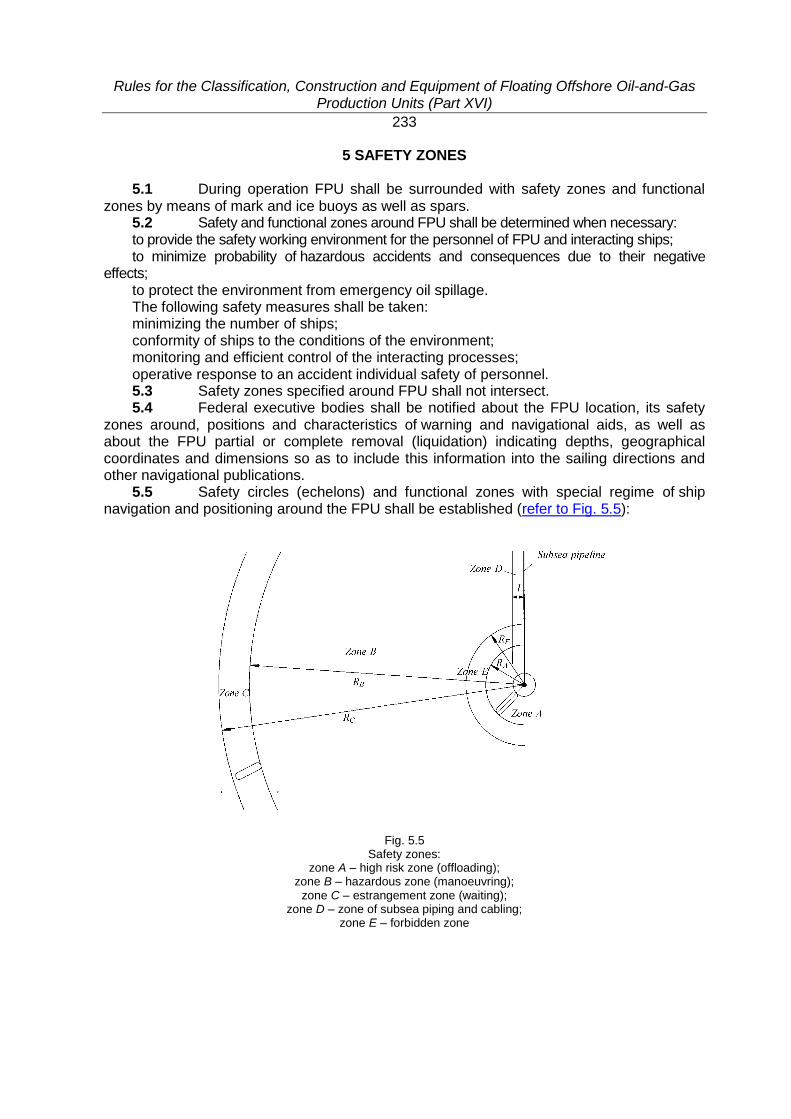
Rules for the Classification, Construction and Equipment of Floating Offshore Oil-and-Gas Production Units (Part XVI)
233
5 SAFETY ZONES
5.1 During operation FPU shall be surrounded with safety zones and functional zones by means of mark and ice buoys as well as spars.
5.2 Safety and functional zones around FPU shall be determined when necessary: to provide the safety working environment for the personnel of FPU and interacting ships; to minimize probability of hazardous accidents and consequences due to their negative
effects; to protect the environment from emergency oil spillage. The following safety measures shall be taken: minimizing the number of ships; conformity of ships to the conditions of the environment; monitoring and efficient control of the interacting processes; operative response to an accident individual safety of personnel. 5.3 Safety zones specified around FPU shall not intersect. 5.4 Federal executive bodies shall be notified about the FPU location, its safety
zones around, positions and characteristics of warning and navigational aids, as well as about the FPU partial or complete removal (liquidation) indicating depths, geographical coordinates and dimensions so as to include this information into the sailing directions and other navigational publications.
5.5 Safety circles (echelons) and functional zones with special regime of ship navigation and positioning around the FPU shall be established (refer to Fig. 5.5):
Fig. 5.5 Safety zones:
zone A – high risk zone (offloading); zone B – hazardous zone (manoeuvring);
zone C – estrangement zone (waiting); zone D – zone of subsea piping and cabling;
zone E – forbidden zone
Rules for the Classification, Construction and Equipment of Floating Offshore Oil-and-Gas Production Units (Part XVI)
234
high risk zone (offloading zone A) in which a tanker is under loading. In these conditions no other ships shall enter this zone except support vessel called for by the FPU operator or master of the tanker for the purpose of rendering assistance and/or preventing accident situation;
hazardous zone (manoeuvring zone B) in which the tanker is manoeuvring so as to approach/depart the FPU. During these manoeuvring operations any other ships except a support vessel called for by the operator or master of the tanker are forbidden to enter this zone;
estrangement zone (waiting zone C) which is specified for anchorage of other ships waiting for the operator's permission to approach the FPU;
zone of subsea piping and cabling (zone D); forbidden zone (zone E). Dimensions and navigation regimes of safety zones as well as the presence of ships
therein shall be set forth for each particular FPU by special instructions and technical specifications which shall be agreed upon with the Register.

EQUIPMENT OF FLOATING OFFSHORE OIL-AND-GAS PRODUCTION UNITS (FPU)
Rules for the Classification, Construction and Equipment of Floating Offshore Oil-and-Gas Production Units (Part I)
236
PART I. LIFE-SAVING APPLIANCES
1 GENERAL
1.1 Life-saving appliances of FPU shall meet the requirements of Part II "Life-Saving Appliances" of the Rules for the Equipment of Sea-Going Ships which are applicable to oil tankers carrying cargoes with the flash point not exceeding 60 °C.
1.2 Life-saving appliances and equipment of survival craft shall be reliable in use during operation under intended climatic conditions.
1.3 FPU to which, by virtue of their designation and purpose the application of the requirements specified in 1.1 rendered unreasonable or impracticable, may waive the requirement when the substantiation is provided according to the procedure approved by the Register.
1.4 Each life boat or liferaft shall be stowed in a safe position and protected from fire and explosion, as far as reasonable and practicable.
Rules for the Classification, Construction and Equipment of Floating Offshore Oil-and-Gas Production Units (Part I)
237
2 SURVIVAL CRAFT
2.1 Each FPU shall be provided on each side with one or more life boats complying with the requirements of 6.18, Part II "Life-Saving Appliances" of the Rules for the Equipment of Sea-Going Ships of an aggregate capacity sufficient to accommodate the total number of persons on board.
2.2 In addition to the requirements of 2.1, liferaft(s) shall be provided, complying with the requirements of 6.8 – 6.12, Part II "Life-Saving Appliances" of the Rules for the Equipment of Sea-Going Ships, capable of being launched on either side of FPU and having an aggregate capacity sufficient to accommodate the total number of persons on board.
2.3 Where the survival craft is stowed in a position from the stem or stern to the closest survival craft is more than 100 m, FPU shall carry, in addition to the life rafts required by 2.2, a life raft stowed as far forward or aft, or one as far forward and another as far aft, as is reasonable or practicable.
Such life rafts may be securely fastened so as to permit manual release. 2.4 Each FPU shall be provided with at least one rescue boat complying with the
requirements of 6.19, Part II "Life-Saving Appliances" of the Rules for the Equipment of Sea-Going Ships.
2.5 A life boat may be accepted as a rescue boat, provided that it and its launching and recovery arrangements also comply with the requirements for rescue boats.
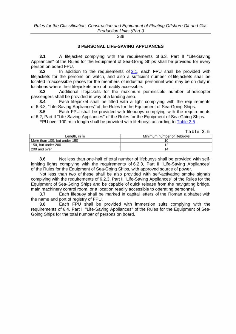
Rules for the Classification, Construction and Equipment of Floating Offshore Oil-and-Gas Production Units (Part I)
238
3 PERSONAL LIFE-SAVING APPLIANCES
3.1 A lifejacket complying with the requirements of 6.3, Part II "Life-Saving Appliances" of the Rules for the Equipment of Sea-Going Ships shall be provided for every person on board FPU.
3.2 In addition to the requirements of 3.1, each FPU shall be provided with lifejackets for the persons on watch, and also a sufficient number of lifejackets shall be located in accessible places for the members of industrial personnel who may be on duty in locations where their lifejackets are not readily accessible.
3.3 Additional lifejackets for the maximum permissible number of helicopter passengers shall be provided in way of a landing area.
3.4 Each lifejacket shall be fitted with a light complying with the requirements of 6.3.3, "Life-Saving Appliances" of the Rules for the Equipment of Sea-Going Ships.
3.5 Each FPU shall be provided with lifebuoys complying with the requirements of 6.2, Part II "Life-Saving Appliances" of the Rules for the Equipment of Sea-Going Ships.
FPU over 100 m in length shall be provided with lifebuoys according to Table 3.5.
T a b l e 3 . 5 Length, in m Minimum number of lifebuoys
More than 100, but under 150 10
150, but under 200 12
200 and over 14
3.6 Not less than one-half of total number of lifebuoys shall be provided with self-
igniting lights complying with the requirements of 6.2.3, Part II "Life-Saving Appliances" of the Rules for the Equipment of Sea-Going Ships, with approved source of power.
Not less than two of these shall be also provided with self-activating smoke signals complying with the requirements of 6.2.3, Part II "Life-Saving Appliances" of the Rules for the Equipment of Sea-Going Ships and be capable of quick release from the navigating bridge, main machinery control room, or a location readily accessible to operating personnel.
3.7 Each lifebuoy shall be marked in capital letters of the Roman alphabet with the name and port of registry of FPU.
3.8 Each FPU shall be provided with immersion suits complying with the requirements of 6.4, Part II "Life-Saving Appliances" of the Rules for the Equipment of Sea-Going Ships for the total number of persons on board.
Rules for the Classification, Construction and Equipment of Floating Offshore Oil-and-Gas Production Units (Part I)
239
4 LIFEBOATS, LIFERAFTS AND RESCUE BOATS ARRANGEMENT. LAUNCHING STATIONS
4.1 Lifeboats, liferafts and rescue boats arrangement, as well as launching
stations shall comply with the requirements of Part II "Life-Saving Appliances" of the Rules for the Equipment of Sea-Going Ships.
4.2 Muster stations shall be provided as close to the embarkation stations as possible. Each muster station shall have sufficient space to accommodate all persons assigned to muster at that station.
4.3 Muster stations shall be readily accessible from accommodation and work areas.
4.4 Muster and embarkation stations shall be adequately illuminated by lighting supplied from the main and emergency sources of power.
Rules for the Classification, Construction and Equipment of Floating Offshore Oil-and-Gas Production Units (Part II)
240
PART II. SIGNAL MEANS
1 GENERAL
1.1 FPU in transit shall be provided with signal navigation lights in compliance with the requirements of Part I "Signal Means" of the Rules for the Equipment of MODU/FOP and the construction of the FPU signal means shall comply with the requirements of Part III "Signal Means" of the Rules for the Equipment of Sea-Going Ships.
1.2 Navigational lights and sound signals at the anchorage shall comply with the requirements of International Lighthouse Service and RF Regulations for Providing Artificial Islands, Installations and Units with Warning Signals and Navigation Equipment (Ministry of Defence Head Office of Navigation and Oceanography of Russian Federation).
1.3 Pyrotechnic signal means shall be provided in compliance with the requirements of 2.5.1 and 3.5.1, Part III "Signal Means" of the Rules for the Equipment of Sea-Going Ships as for oil tankers.
1.4 Landing areas and obstacles to helicopter operations shall be marked and illuminated in compliance with the General Aviation Requirements for Maintenance of Helicopters on Board Ships and Raised Platforms (OAT GA).
1.5 Places of location of mooring arrangements shall be marked by special lights, the range of visibility shall comply with meteorological conditions (fog, precipitations) under which the mooring is permitted.
1.6 Fitting and installation of lights and means specified in 1.2, 1.4 and 1.5 are subject to technical supervision by the relevant competent bodies.
Rules for the Classification, Construction and Equipment of Floating Offshore Oil-and-Gas Production Units (Part III)
241
PART III. RADIO EQUIPMENT
1 GENERAL
1.1 The requirements of this Part apply to the radio equipment of FPU in addition to the requirements of Part IV "Radio Equipment" of the Rules for the Equipment of Sea-Going Ships, unless otherwise specified.
Rules for the Classification, Construction and Equipment of Floating Offshore Oil-and-Gas Production Units (Part III)
242
2 LIST OF RADIO EQUIPMENT
2.1 Each FPU shall be provided with radio equipment, depending on the radio equipment complement of towing or escort vessel.
Where the towing or escort vessel is equipped in accordance with the requirements of Section 2, Part IV "Radio Equipment" of the Rules for the Equipment of Sea-Going Ships, FPU shall be provided with the following radio equipment:
.1 VHF radio installation;
.2 MF radio installation;
.3 VHF EPIRB or satellite EPIRB depending on the sea area;
.4 facilities for reception of maritime safety information depending on the sea area: NAVTEX service receiver, EGC receiver, HF direct-printing radiotelegraph receiver. Where the towing or escort vessel is not equipped in accordance with the requirements
of Section 2, Part IV "Radio Equipment" of the Rules for the Equipment of Sea-Going Ships, FPU shall be provided with the full list of radio equipment meeting the requirements of Section 2, Part IV "Radio Equipment" of the Rules for the Equipment of Sea-Going Ships.
2.2 When FPU is in tow mode with no persons on board, the radio equipment specified in 2.1 may not be installed.
2.3 FPU in operating or severe storm condition shall be provided with the main and duplicating radio equipment. Completion of such equipment shall be determined in accordance with 2.6.3 and Table 2.2.1, Part IV "Radio Equipment" of the Rules for the Equipment of Sea-Going Ships, depending on the sea area of the FPU location.
2.4 Each FPU served by helicopters shall be provided with the two-way VHF radiotelephone apparatus for communication with aircrafts.
2.5 Each FPU shall be provided with effective means of communication between the main machinery control room and any station or stations, which have means of radio equipment control.
2.6 FPU shall be fitted with a security alarm system. 2.7 All FPU radio equipment shall meet the technical requirements given in
Part IV "Radio Equipment" of the Rules for the Equipment of Sea-Going Ships. 2.8 The radio equipment installed in hazardous zones or being portable shall be
of intrinsically safe type.

Rules for the Classification, Construction and Equipment of Floating Offshore Oil-and-Gas Production Units (Part III)
243
3 RADIO EQUIPMENT ARRANGEMENT
3.1 The control of radio equipment shall be carried out from the position where FPU is routinely controlled when in tow, and where a constant watch is kept while FPU is under operating or severe storm condition.
3.2 The duplicating radio equipment shall be arranged in a space, placed as far as possible from the location of the main radio equipment so that no single accident in any part of FPU could disable all means of radio communications.
3.3 If under operational conditions of FPU the acoustic noise level in spaces fitted with radio equipment is high and may interfere in the proper use of radio equipment, then the relevant noise protection shall be provided.
Rules for the Classification, Construction and Equipment of Floating Offshore Oil-and-Gas Production Units (Part III)
244
4 AERIALS
4.1 Transmitting aerials shall be located outside hazardous zones. 4.2 All transmitting and receiving aerials shall not be within 9 m from cargo crane
booms and other high metal structures, which can give rise to screening effect.
Rules for the Classification, Construction and Equipment of Floating Offshore Oil-and-Gas Production Units (Part IV)
245
PART IV. NAVIGATIONAL EQUIPMENT
1 GENERAL
1.1 The requirements of this Part apply to the FPU navigational equipment and supplement the requirements of Part V "Navigational Equipment" of the Rules for the Equipment of Sea-Going ships.
1.2 The FPU navigational equipment shall be installed in such a number and to have such technical performance as to ensure:
.1 determination of its own position and observation of surrounding conditions;
.2 the independent navigational support of a self-propelled FPU in sea transit while following to the operational location.

Rules for the Classification, Construction and Equipment of Floating Offshore Oil-and-Gas Production Units (Part IV)
246
2 LIST OF NAVIGATIONAL EQUIPMENT
2.1 Depending on the group to which the particular FPU is related, it shall be provided with the navigational equipment in accordance with Table 2.1.
T a b l e 2 . 1
Nos Item
Quantity in groups
Self-propelled
Non-self-propelled
1 Standard magnetic compass 1 –
2 Steering magnetic compass installed at the main steering position 1 –
3 Gyrocompass 1 –
4 Dynamic pressure log, induction log or other of a ground type 1 –
5 Echo sounder 1 –
6 Automatic identification system (AIS) equipment 1 1
7 Radionavigation system/systems receiver 1 1
8 Hand lead 1 –
9 Navigational sextant 1 –
10 Chronometer 1 –
11 Stopwatch 2 1
12 Prismatic binocular 3 2
13 Anemometer 1 1
14 Barometer 2 1
15 Inclinometer 2 2
16 Sea water and air temperature indicator 1 1
17 Wave parameters indicator 1 1
18 Sea current speed and direction indicator 1 1
19 Radar station 1 1
2.2 The self-propelled FPU engaged on international voyages and constructed on
or after 31 December 2008 shall be equipped with the system of long-range identification and tracking of ships (LRIT system).
The self-propelled FPU engaged on international voyages, constructed before 31 December 2008 and intended for navigation in sea areas A1 and A2 or in sea areas A1, A2 and A3, shall be equipped with LRIT system not later than the first survey of the radio installation after 31 December 2008.
The self-propelled FPU engaged on international voyages, constructed before 31 December 2008 and intended for navigation in sea areas A1, A2, A3 and A4 shall be equipped with LRIT system not later than the first survey of the radio installation after 1 July 2009. However, whilst these self-propelled FPU operate within sea areas A1, A2 and A3 they shall be equipped with LRIT system not later than the first survey of the radio installation after 31 December 2008.
LRIT system is not obligatory for FPU, irrespective of the date of construction, fitted with an automatic identification system (AIS) and intended to operate exclusively within sea area A1.
Rules for the Classification, Construction and Equipment of Floating Offshore Oil-and-Gas Production Units (Part IV)
247
3 NAVIGATIONAL EQUIPMENT ARRANGEMENT
3.1 The navigational devices listed in Table 2.1 shall be installed in the control station.
3.2 The navigational equipment shall not be installed in hazardous spaces and areas, unless it is of the appropriate intrinsically safe type.
Rules for the Classification, Construction and Equipment of Floating Offshore Oil-and-Gas Production Units (Part V)
248
PART V. EQUIPMENT AND ARRANGEMENTS FOR PREVENTION OF POLLUTION OF THE ENVIRONMENT
1 GENERAL
1.1 The requirements of this Part apply to the FPU construction, arrangements, equipment and systems intended for the prevention of pollution by oil, sewage, and garbage, as well as air pollution.
1.2 The requirements are specified in Part XX "Equipment for Prevention of Pollution" of the Rules for the Equipment of MODU/FOP and covers:
Annex I to MARPOL 73/78, "Regulations for the Prevention of Pollution by Oil"; Annex IV to MARPOL 73/78, "Regulations for the Prevention of Pollution by Sewage
from Ships"; Annex V to MARPOL 73/78, "Regulations for the Prevention of Pollution by Garbage
from Ships"; Annex VI to MARPOL 73/78, "Regulations for the Prevention of Air Pollution from
Ships". The application of the requirements of Annex I to MARPOL specially to FPU is regulated
by the IMO Guidelines adopted by IMO resolution MEPC.139(53) as amended by
IMO resolution MEPC.142(54).

Российский морской регистр судоходства
Правила классификации, постройки и оборудования морских плавучих нефтегазодобывающих комплексов
Russian Maritime Register of Shipping
Rules for the Classification, Construction and Equipment of Floating
Offshore Oil-And-Gas Production Units
The edition is prepared
by Russian Maritime Register of Shipping 8, Dvortsovaya Naberezhnaya,
191186, St. Petersburg, Russian Federation
www.rs-class.org/en/