Embed Size (px)
Citation preview

Minitrend QX & Multitrend SX Recorders
See, Store and Send Data Securely
For the best in data acquisition, data securityand peace of mind .. choose

43-TV-25-30 Iss.2 GLO June 06 UK ii

Table of Contents
Section 1: Preface .............................................................................. 1Preface ........................................................................................................... 1
Thank you for choosing a Honeywell X Series recorder .......................................... 1Supplementary documentation ................................................................................. 1Notes ......................................................................................................................... 1Trademarks ............................................................................................................... 1
Safety ............................................................................................................. 2Symbols ..................................................................................................................... 2Static Electricity........................................................................................................ 3
Protocols used in this manual ........................................................................ 3Safety and Symbol Identification .............................................................................. 3
Warnings and Safety Precautions .................................................................. 3Do’s and Don’ts......................................................................................................... 3Hazardous Voltage.................................................................................................... 4
Section 2: Installation .........................................................................................5Environment and Location ............................................................................ 5Mechanical Installation .................................................................................. 6
Installation Instructions............................................................................................ 9Electrical Installation ................................................................................... 12
Installation Category.............................................................................................. 12Analogue Input Card .............................................................................................. 15Analogue Output Card............................................................................................ 17Pulse Input Card..................................................................................................... 18Transmitter Power Supply Card ............................................................................. 19Alarm Relay Cards & Digital Input/Output Cards................................................. 20Communications Connections ................................................................................ 23USB Devices ........................................................................................................... 24
Section 3: Overview ..........................................................................................25Functions and Features ................................................................................ 25
Recorder Functionality ........................................................................................... 27Features .................................................................................................................. 28Options - Hardware ................................................................................................ 30
Section 4: Recorder Setup ................................................................................35Power up ...................................................................................................... 35
1. Menu Access ....................................................................................................... 352. Log On/Off .......................................................................................................... 363. Local Settings ..................................................................................................... 364. Time and Date Settings ....................................................................................... 375. Firmware Options............................................................................................... 37Menu Path............................................................................................................... 37Help ........................................................................................................................ 37Main Menu.............................................................................................................. 38
43-TV-25-30 Iss.2 GLO June 06 UK iii
Configure Menu....................................................................................................... 39Setup Menu.............................................................................................................. 40Layout...................................................................................................................... 78Passwords................................................................................................................ 80Settings .................................................................................................................... 83Alarms Menu ........................................................................................................... 85Screen Menu ............................................................................................................ 86Batch Setup/Batch Control...................................................................................... 87Recording Menu ...................................................................................................... 90Messages Menu ....................................................................................................... 92Process Menu .......................................................................................................... 95Status Menu ............................................................................................................. 96
Finish ..........................................................................................................104
Section 5: Password Security ....................................................................... 105Log On/Off ............................................................................................................ 105Users and Groups.................................................................................................. 105Administrator ........................................................................................................ 105Password Policy .................................................................................................... 107User Interface requirements.................................................................................. 108Audit Trail ............................................................................................................. 108Level Permissions.................................................................................................. 109Default Password Access ...................................................................................... 111
Section 6: Screen Configuration ................................................................... 119Process Screen Overview ...................................................................................... 119Menu Bar............................................................................................................... 120Screen Menu Bar ................................................................................................... 121Screen Activity ....................................................................................................... 124Screen Designer Screens ....................................................................................... 128
Section 7: Firmware Options ......................................................................... 129Firmware Credit System .............................................................................129
Firmware Options ................................................................................................. 130Applying your Firmware credits ........................................................................... 130Remote Viewer....................................................................................................... 131
Section 8: Communication ............................................................................ 133Comms Configuration ................................................................................133
Standard Communication Interfaces..................................................................... 133Protocols .....................................................................................................134
USB Barcode Reader............................................................................................. 135Comms and Trend Manager Pro Suite .......................................................135
Software Installation ............................................................................................. 135System Setup.......................................................................................................... 135Data logging and transfer ..................................................................................... 136PC Ethernet connections....................................................................................... 136Getting connected - IP Address............................................................................. 137Local Area Network setup ..................................................................................... 138Links to Remote Networks ..................................................................................... 139OPC Interface - Open Process Control................................................................. 140OPC Clients .......................................................................................................... 142Web Browser.......................................................................................................... 142
iv 43-TV-25-30 Iss.2 GLO June 06 UK

Communications Server ............................................................................. 143Comms Server Overview ...................................................................................... 143Comms Server Status Screen ................................................................................ 146Comms Server Setup............................................................................................. 149
Comms Server Database ............................................................................ 152System Setup ......................................................................................................... 153
Section 9: PC Software Suite .........................................................................155The TrendManager Pro Software Suite ................................................................ 155
Section 10: Spares List ...................................................................................157Minitrend QX Recorder ........................................................................................ 157Multitrend SX Recorder ........................................................................................ 161
Section 11: Instrument Care and Maintenance .............................................167Cleaning Instructions ................................................................................. 167Backlights .................................................................................................. 167Operating Temperature .............................................................................. 167Touch Screen ............................................................................................. 167Calibration ................................................................................................. 168
Section 12: Technical Data & Specifications ................................................169Field IO Specification ................................................................................ 169Analogue Input .......................................................................................... 170Alarm/Digital Input Specification ............................................................. 170
Alarm/Relay Output Card Options ....................................................................... 170Digital Input Cards............................................................................................... 171
Specification Tables ................................................................................... 173Specification Design Attributes ....................................................... 173Specification Analogue Inputs .......................................................... 175Specification Logging .................................................................. 176Specification Physical Parameters ................................................... 176Input Range Performance Accuracy Table........................................................... 177Input Actuation (Linear) ................................................................................................................. 177Specification Options................................................................ 178Specification Environmental and Operating Conditions.......................... 179LED Flash Codes.................................................................................................. 180
Appendix A: Quality and Safety .....................................................................181CE Mark ..................................................................................................... 181Safety ......................................................................................................... 181
Appendix B: Maths Expressions ....................................................................183Full Maths & Script Processing ................................................................. 183
Maths Variable and Function Tables .................................................................... 184Full Maths............................................................................................................. 190Script Function Application Examples ................................................................. 191Maths Error Messages.......................................................................................... 195
43-TV-25-30 Iss.2 GLO June 06 UK v

Appendix C: Thermocouple Connections .................................................... 197How Thermocouples work .........................................................................197Thermocouple CJC Compensation .............................................................198
Internal Automatic ................................................................................................ 198Ext 0°C Reference ................................................................................................. 199External with a Specified Temperature ................................................................. 199External Input Reference....................................................................................... 200
Appendix D: Alarms ....................................................................................... 201Alarms Menu ......................................................................................................... 201
Appendix E: Ethernet ..................................................................................... 203Ethernet ................................................................................................................. 203
Appendix F: Fuzzy Logging ........................................................................... 205
Appendix G: F sub zero Sterilisation ............................................................ 209The significance of F0........................................................................................... 209
Appendix H: Calibration ................................................................................. 211AI Calibration and CJC Calibration ...........................................................211Sensor Compensation .................................................................................211
Appendix I: Battery Data ................................................................................ 213Location: Processor Board .........................................................................213
Safety Guidelines................................................................................................... 213
Appendix J: Function Codes and Memory Maps ........................................ 215Modbus Memory Map Supplement: ...........................................................215
Totalisers ............................................................................................................... 215Input Text message ................................................................................................ 215Analogue Input Value ............................................................................................ 216Communications Input .......................................................................................... 216Pen Values ............................................................................................................. 216
Modbus Function Codes .............................................................................216
Index ................................................................................................................ 217
vi 43-TV-25-30 Iss.2 GLO June 06 UK

Section 1: Preface
Preface
Thank you for choosing a Honeywell X Series recorderThank you for purchasing the newest in our range of electronic data recording for Honey-well X Series Advanced Graphic Recorders. The Minitrend QX and Multitrend SX paperless chart recorders are the latest develop-ment of the solid-state replacement for traditional paper recorders.
Many options, features and functions are available to meet a wide range of applications and requirements including: Power, Water Treatment, Thermal Processing, Food and Beverage, Pharmaceutical/Biotech and Manufacturing industries.
This manual explains the product functionality operation, configuration and communication as well as Safety Precautions, Installation & Wiring, Recorder Setup, Troubleshooting and Spares List. It is recommended that the user reads the manual before installing and operat-ing the recorder.
Supplementary documentationSupplementary documentation to accompany these recorders are:
Documents can be downloaded from the web site at www.XSeries-info.net.
Notes
• The contents of this manual are correct at the time of issue. The contents may change at any time without prior notification. This is due to continuous develop-ments to the recorder and it’s functionality.
• Every effort has been made to ensure the accuracy of this document, however should there be any anomalies found, please contact your nearest Honeywell supplier. See back page for contact addresses.
• All rights are reserved. No part of this manual should be copied or reproduced, stored on a retrieval system or transmitted in any form without the prior permission from Honeywell International Inc.
Trademarks
• Microsoft, MS-DOS, Windows, Windows 2000, Windows XP and Windows CE are all registered trademarks of Microsoft Corporation.
Table 1.1 : Supplementary recorder documentation
Manual Part number
TrendManager Pro V5 & X Series Software Suite 43-TV-25-11
Screen Designer X Series Recorders 43-TV-25-31
Specification - Minitrend QX 43-TV-03-10
Specification - Multitrend SX 43-TV-03-11
43-TV-25-30 Iss.2 GLO June 06 UK 1

Safety
• Compact Flash® and CF (logo) are trademarks of the Compact Flash Association (CFA).
• For the purpose of this manual the ™ and ® symbols will not follow their own trade-mark names or registered trademark names in every instance.
• Company names and Product names mentioned in this manual are trademarks or registered trademarks of their individual owners.
SafetyThe X Series range of instruments is compliant with the requirements of BS EN 61010-1:2001 “Safety Requirements for Electrical Equipment for Measurement, Control and Labo-ratory Use” and UL 61010C-1 and CSA 22.2-1010.1, as options. If the equipment is used in a manner not specified, the protection provided by the equipment may be impaired.
The X Series range of instruments is compliant to the requirements for Class 1, Div.2 Haz-ardous (Classified) Locations.
SymbolsOne or more of the following symbols may appear on the recorder labelling.
Table 1.2 : Safety Symbols
Symbol Meaning
Caution - refer to manual for instructions
Caution - risk of electric shock
Direct Current
Protective conductor terminal
Earth (ground) terminal
Static Electricity
2 43-TV-25-30 Iss.2 GLO June 06 UK

Protocols used in this manual
Static ElectricityAll circuit boards and electronic modules associated with this recorder contain components which are susceptible to damage caused by electrostatic discharge. Should it be necessary to handle such components, appropriate precautions in accordance with ANSI/ESD S20.20 Electrostatic Discharge Control Program Standard, should be observed.
Protocols used in this manual
Safety and Symbol Identification
Warnings and Safety Precautions
Do’s and Don’ts
1. Before any connections are made to the recorder, ensure the protective earth terminal is connected to a protective conductor before applying power or any other connections.
Directive 2002/96/ECWEEE: Waste Electrical and Electronic Equipment
Table 1.2 : Safety Symbols
Symbol Meaning
Table 1.3 :
Symbol Description
WARNING The WARNING symbol indicates a potentially hazardous situation, which, if not avoided, could result in death or serious injury.
CAUTION This CAUTION symbol may indicates a potential-ly hazardous situation, which, if not avoided, may result in property damage.
NOTICE A NOTICE symbol indicates important informa-tion that must be remembered and aids in job performance.
WARNINGIMPROPER INTERRUPTION OF CONNECTIONSAny interruption of the protective conductor outside the recorder, or disconnection of the protective earth terminal is likely to make the recorder dangerous under some fault conditions. Intentional interruption of the protective conductor is dangerous.
Failure to comply with these instructions could result in death or serious injury.
43-TV-25-30 Iss.2 GLO June 06 UK 3

Warnings and Safety Precautions
In order to comply with the requirements of safety standard EN 61010-1:2001, the recorder should have one of the following as a disconnecting device, located within easy reach of the operator, and be clearly labelled as the disconnecting safety device:
• A switch or circuit breaker which complies with the requirements of IEC 60947-1 and IEC 60947-3.
• A separable coupler which can be disconnected without the use of a tool.
• A separable plug, without a locking device, to mate with a socket outlet in the building.
2. Whenever it is likely that protection has been impaired, the recorder should be made inoperative and secured against operation. The manufacturer's service centre should be contacted.
3. Repair is not to be attempted by a customer. Any adjustment or maintenance expected of an operator as part of the normal operation of the product is referred to as Opera-tional Maintenance. Any maintenance not expected of the operatoris referred to as Corrective Maintenance and is to be carried out only by authorized service personnel or returned to an authorized repair centre.
4. Where conductive pollution such as condensation or conductive dust is present, ade-quate air conditioning, filtering and/or sealing must be installed.
5. This recorder contains one battery on the Processor board which must be treated and disposed of with care. Batteries must not be short circuited. Batteries should be dis-posed of in accordance with local regulations, they must not be disposed of with normal refuse.
6. Improper signal and supply wiring - WARNING
7. If the equipment is used in a manner not specified by the manufacturer, the protection provided by the equipment may be inadequate.
8. The protective earth terminal must remain connected (even if the recorder is isolated from the mains supply) if any of the measuring, communications, or relay terminals are connected to hazardous voltages.
Hazardous VoltageHazardous Voltages are defined by EN61010-1 as follows:
WARNINGIMPROPER SIGNAL AND SUPPLY WIRINGSignal and supply wiring should be kept separate. Where this is impractical, shielded cables should be used for the signal wiring. Where signal wiring is carrying, or could carry under fault conditions, hazardous voltage (defined as >30 V rms and 42.4 V peak, or >60 Vd.c.), double insulation must be used for all signal wiring.
Failure to comply with these instructions could result in death or serious injury.
WARNINGHAZARDOUS VOLTAGE LEVELSVoltage levels above 30V rms and 42.4V peak or 60V dc are deemed to be "Hazardous Live".
Failure to comply with these instructions could result in death or serious injury.
4 43-TV-25-30 Iss.2 GLO June 06 UK

Section 2: Installation
Damage checks Any damage caused to the recorder or the contents should be reported immediately to your shipper.
UnpackingRemove the contents, check the packaging and remove all documentation and accessories supplied. Retain the box and any packaging for future transportation.
ContentsCheck that the contents and accessories are correct against the order or Model Selection Guide using the model number on the recorder. Contact your authorised Honeywell distrib-utor or Honeywell immediately should there be any query.
The contents are based on Unit Model Number ordered and will vary from unit to unit. The following list is provided as a general guide and not specific to any single unit.
• Recorder - specification as ordered (check against the Model Selection Guide)
• Mounting fixings - Mounting clamps and panel gasket
• Connector kit - mating half connectors to recorder spec. Including a CJC connector for Thermocouple operation.
• Quick Start Guide - to get you started
• First time Password system instructions - for ESS recorders only
• CD - Viewer software + documentation
• Plastic stylus x 2 (for use with the touch screen)
• Manual (optional) - Hardcopy English, French or German
• Any other items ordered as an option (Table VI in the Model Selection Guide)
Re-packing
Environment and Location• The recorder is designed to be mounted into a panel. See “Installation Instruc-
tions” on page 9.
• Mount in a suitable location where the ideal viewing angle will not exceed 65° from the left or right, 65° looking down and 40° looking up at the recorder display.
• The location should be free from vibration.
• The environment should be of non-condensing humidity.
• The ambient temperature should be between 0°C and 50°C.
• The relative humidity should be between 10% to 90%.
NOTICEShould the original packing be destroyed or lost, new packaging can be ordered or as a last alternative, then ONLY pack the recorder in polystyrene granules if the recorder is FIRST sealed in a strong plastic bag. Failure to do this will invalidate your warranty.
43-TV-25-30 Iss.2 GLO June 06 UK 5
Mechanical Installation
Mechanical InstallationMounting and Viewing AnglesBoth the Minitrend QX and Multitrend SX recorders have an unlimited mounting angle. For the best view of the display the viewing angle should not exceed 65° from the left or right, 65° look-ing down and 40° looking up at the recorder display.
Panel cut-out size for the Minitrend QX recorder
Please note the recommended spacing for adjacent mounting
Panel Cut-out
Panel Cut-out
Panel Cut-out
138.00(5.43”)
138.00(5.43”)
>7.00(0.28”)>6.00
(0.237”)
+1- 0
+1- 0
Figure 2.1 Minitrend QX Panel cut-out
6 43-TV-25-30 Iss.2 GLO June 06 UK

Mechanical Installation
Panel cut-out size for the Multitrend SX recorder
The Minitrend QX and Multitrend SX recorders are DIN Standard sizes and should be pan-el mounted.
Panel Cut-out
Panel Cut-out
Panel Cut-out
281.00(11.06”)
281.00(11.06”)
>20.00(0.787”)>20.00
(0.787”)
Please note the recommended spacing for adjacent mounting
Figure 2.2 Multitrend SX Panel cut-out
43-TV-25-30 Iss.2 GLO June 06 UK 7

Mechanical Installation
Minitrend QX Dimension details
4 Mounting clamp positions. For standard units fit only two brackets on opposite sides of the unit, either top and bottom or left and right slots. NEMA 4X rated recorders require all four mounting brackets to be fitted.
Figure 2.3 Minitrend QX Recorder dimensions
8 43-TV-25-30 Iss.2 GLO June 06 UK

Mechanical Installation
Multitrend SX Dimension details
Installation Instructions
• Minimum panel thickness = 2mm (0.078”), max = 20mm (0.78”)
• Both recorders must be inserted from the front of the panel,
• Two mounting clamps are supplied and can be fixed either on the top and bottom sides or on the left and right sides of the case.
4 Mounting clamp positions. For standard units fit only two brackets on opposite sides of the unit, either top and bottom or left and right slots. NEMA 4X rated re-corders require all four mounting brackets to be fitted.
Figure 2.4 Multitrend SX recorder dimensions
43-TV-25-30 Iss.2 GLO June 06 UK 9

Mechanical Installation
Panel Mounting Clamp InstallationThe Minitrend QX and the Multitrend SX recorders slide into the panel cut-out and are held in place by two (or four) panel clamps. The panel clamps should be fitted on diagonally op-posite sides of the unit and tightened against the rear of the panel using two fixing screws.
The mounting clamp assembly and fitting instructions differ slightly for the two recorders.Minitrend QX
1. Insert the panel gasket onto the recorder so it goes between the back of the recorder bezel and the panel. From the front panel, place unit in the panel and push through the panel.
2. To loosen each clamp, unscrew the long screw to accommodate the panel thickness.
3. From behind the panel, the orientation of the clamp should be with the screw head towards the rear of the unit. See Figure 2.1 on page 11
4. Take the first clamp and locate the two lugs on the clamp into the slots on the unit. See Figure 2.1 on page 11
5. Take the second clamp and do the same but in the diagonal position to the opposite side. See Figure 2.3 on page 8
6. Tighten the screw using a flat blade screwdriver and the clamp will secure against the panel.
Multitrend SX
1. Insert the panel gasket onto the recorder so it goes between the back of the recorder bezel and the panel. From the front panel, place unit in the panel and push through the panel.
2. To loosen each clamp, unscrew the long screw to accommodate the panel thickness.
3. From behind the panel, the orientation of the clamp should be with the screw head towards the rear of the unit. See Figure 2.2 on page 11
4. Position the circular mounting boss in the hole on one side of the case with the lip of the boss inside the case. Ensure the front of the clamp is up against the panel.
5. Fix the second clamp on the opposite side of the unit. See Figure 2.4 on page 14
6. Tighten the screw using a flat blade screwdriver and the clamp will secure against the panel.
CAUTIONCONTROL UNIT DAMAGEDo not over tighten mounting clamp screws. Minitrend QX torque setting should be 0.5 - 0.75Nm/4.4 - 6.6lbf-in
Multitrend SX torque setting should be 0.5 - 0.70Nm/4.4 - 6.2lbf-in
Failure to comply with these instructions may result in product damage
10 43-TV-25-30 Iss.2 GLO June 06 UK

Mechanical Installation
Mounting Clamp Diagram
2 mounting clamp positions, one re-quired on either side of the unit
Mounting clamp slots
Figure 2.1 QX Mounting clamp
Figure 2.2 SX Mounting clamp
4 mounting clamp positions (2 shown). 2 clamps are re-quired on opposite sides of the unit
43-TV-25-30 Iss.2 GLO June 06 UK 11

Electrical Installation
Electrical Installation
Installation Category
• Installation category - Installation category II, Pollution degree 2
• Follow National and local electrical codes for installation in a Class 1, Div.2 area.
For voltage, frequency and power refer to the appropriate Specification sheet: See “Sec-tion 12: Technical Data & Specifications” on page 169.
FusesThere is a fuse situated on the DC input version power supply, type 2A time-delay, this can be replaced by the user. Replacement of fuses should be carried out by qualified service personnel.
If the fuse should blow again there is probably a problem elsewhere within the unit and the recorder should be returned for inspection to your authorised Honeywell distributor or Hon-eywell Service department.
CablesTo fully comply with the requirements of the CE Mark, all cables connected to the rear of the unit should use screened cable terminated at both ends. A low impedance earth cable (<50 mΩ) must be connected to the earthing stud on the rear of the recorder, to ensure that the recorder is always earthed.
Before performing any installation please read the section on “Safety” on page 2.and “Warnings and Safety Precautions” on page 3.All connections to the unit are made via the rear panel, the layout of which is shown in Fig-ure 2.3 on page 13
Signal Wiring
The Honeywell recorder is intended for panel-mount use, and only the front face is intend-ed to be exposed to the operator. Disconnection from the supply MUST be made possible by means of a switch, circuit breaker or other means of supply isolation. The disconnection device must be included in the panel installation, clearly marked, in close proximity to the Honeywell equipment, and within easy reach of the operator. The protective earth termi-nal must remain connected (even if the recorder is isolated from the mains supply) if any of the analogue or relay terminals are connected to hazardous voltage.
WARNINGENSURE SAFETY EARTH CONNECTIONAlways ensure the unit is connected to safety earth when connecting to an AC or DC supply.
Failure to comply with these instructions could result in death or serious injury.
12 43-TV-25-30 Iss.2 GLO June 06 UK
Electrical Installation
AC PowerAC supply is connected via the standard configuration IEC chassis plug on the rear panel, 100 - 250 Vac, 50-60 Hz (40 VA Minitrend QX, 60VA Multitrend SX). Absolute limits 90V-132Vac and 180V-264Vac
24V DC Power / 24V AC PowerSupply range is 24V DC +/- 10% (absolute limits are 20V to 50V DC). Also accepts 20 to 30V AC. Power to the D.C.variant is connected via a rectangular 3-way connector as iden-tified in Figure 2.3 on page 13 for the Minitrend QX and Figure 2.4 on page 14 for the Multitrend SX.
WARNINGHAZARDOUS VOLTAGESWhen using the recorder as portable equipment the optional rear cover must be fitted when hazardous voltages are connected.
Failure to comply with these instructions could result in death or serious injury.
Figure 2.3 QX Connector diagram
Earth screw (ground)
24V DC/AC Input
24V TX Power Supply Output
SPNC Relay
AC supply 100 - 250 VAC
Analogue Input /Analogue Output /or Pulse InputSlot ASlot B
Alarm Relay or Digital I/O Slot G
RS485USB Host
Wire seal provision
Ethernet
CJC Sensor
43-TV-25-30 Iss.2 GLO June 06 UK 13

Electrical Installation
Card and Slot positions
Table 2.1 : Card priority positions
Cards Minitrend QX Multitrend SX
Analogue Input card A, B A, B, C, D, E, F
Analogue Output card B E, F
Pulse Input card A, B A, B, C, D, E, F
Alarm Relay or Digital I/O card G G, H, I
Earth screw (ground)
24V DC/AC Input
SPNC Relay
24V TX Power SupplyOutput
LED
AC supply 100 - 250 VAC
Analogue Input/Analogue Output/or Pulse Input
Slot A
Slot B
Slot C
Slot D
Slot E
Slot F
Alarm Relay or Digital I/O
Slot G
Slot H
Slot I
Ethernet
RS485 USB Host
Figure 2.4 SX Rear panel
CJC Sensor position in the middle of the Analogue Input connector. Slots A - F
14 43-TV-25-30 Iss.2 GLO June 06 UK

Electrical Installation
Analogue Input CardEach Analogue Input card has up to 8 input channels. Connections are made via 2 x 12-way screw terminal plugs that fit into a PCB header on the rear of the unit. The 2-way CJC sensor should remain fitted in the central 2-way header.
The Minitrend QX can have two analogue input cards fitted giving up to 16 input channels (2 x 8 channel cards). The slot positions are A & B, these are identified on the rear panel on the back of the unit. Either slot can be used, it is recommended that slot A is used if only one card is fitted.
The Multitrend SX can have up to 6 analogue input cards fitted, up to 48 input channels. The slot positions A, B, C, D, E or F; these are identified on the rear panel. PC boards are fitted in order, slot ”A” starts from the top.
For more information of setting up calibration for an Analogue card, see “Calibration” on page 71.
Analogue Input Channel NumbersAnalogue Input cards are either 4, 6 or 8 channels with a full length connector taking up 8 channels even if only 4 or 6 are operational.
Table 2.2 :
Analogue Input card
CardPosition
Slot A Slot B Slot C Slot D Slot E Slot F
Channel number
1 to 8 9 to 16 17 to 24 25 to 32 33 to 40 41 to 48
WARNINGHAZARDOUS VOLTAGESInsulation from channel to channel: Normally a channel can be safely connected to a hazardous voltage up to 300V AC common mode* with respect to earth. However, where a channel is connected to a safety low voltage circuit, an immediately adjacent channel must be adequately insulated from hazardous voltages between 150V AC and 300V AC max. This insulation should comprise of at least 1.5mm air gap, or a bar-rier rated greater than 1400V AC. This is to ensure that protection of the safety low voltage circuit is fully maintained.*Common Mode voltage is a voltage applied between the whole channel and earth, not between pins on a channel. 300V AC is permitted at Measurement Category CAT ll (Overvoltage Category ll)
Failure to comply with these instructions could result in death or serious injury.
NOTICEFor 12 and 24-way connectors; torque setting 0.4 Nm/3.5lbf-in. Do not over tighten. Recommended wire size for termination connector is 22-12 AWG (22-14 SWG)
43-TV-25-30 Iss.2 GLO June 06 UK 15

Electrical Installation
Analogue Input Connection Details
Current InputFor Current (mA) Input fit a 10Ω resistor across the + and - pins of the 12-way mating half analogue connector. Figure 2.6 on page 16 shows a 10Ω (±0.1%) resistor fitted to chan-nel 5 for a current (mA) input.
ThermocouplesEnsure polarity of thermocouple is correct.
Resistance ThermometersIf using 2 or 3 wire R/T the + and - terminals must be linked together. See Figure 2.6 on page 16.
Analogue Input Signal Wiring
CH1 CH2 CH3 CH4 CH5 CH6 CH7 CH8
CJC
Figure 2.5 Analogue Input connector
-ve +ve
Current
10R
Ohms
R/T R/T
2-wire R/T3-wire R/T
-ve +ve
Figure 2.6 Input signal wiring
+ve optional connection
Passive Burnout ThermocouplesVolts/mV
-ve +ve -ve +ve
Active Burnout Thermocouples
R/T
4-wire R/T
16 43-TV-25-30 Iss.2 GLO June 06 UK

Electrical Installation
CJC ConnectorsThe CJC connector resides between channel 4 and channel 5 on the Analogue Input card. For information on connecting the CJC sensor, see Figure 2.5 on page 16.
Analogue Output CardThe Analogue Output card connections are made via 1 x 12-way screw terminal plug that fits into a PCB header on the rear of the unit.
The Analogue Output card position for the Minitrend QX is shown in Figure 2.3 on page 13, and Figure 2.4 on page 14 for the Multitrend SX.
Analogue Output Channel NumbersThe Analogue Output cards are either 2 or 4 channels using a connector that only takes up half the length of the connector slot. Looking from the rear of the unit the Analogue Out con-nector is on the left of the Analogue slot with a blanking plate on the right.
CAUTION
CONTROL UNIT DAMAGEDo not apply a hazardous live voltage between + and - pins within a channel. (eg. 60V maximum on voltage ranges, 1.2V maximum on millivolts ranges). Do not apply a volt-age above 1.2V to the * pin.
Failure to comply with these instructions may result in product damage
WARNINGHAZARDOUS VOLTAGESInsulation from channel to channel: Normally a channel can be safely connected to a hazardous voltage up to 300V AC common mode* with respect to earth. However, where a channel is connected to a safety low voltage circuit, an immediately adjacent channel must be adequately insulated from hazardous voltages between 150V AC and 300V AC max. This insulation should comprise of at least 1.5mm air gap, or a barrier rated greater than 1400V AC. This is to ensure that protection of the safety low voltage circuit is fully maintained.*Common Mode voltage is a voltage applied between the whole channel and earth, not between pins on a channel. 300V AC is permitted at Measurement Category CAT ll (Overvoltage Category ll)
Failure to comply with these instructions could result in death or serious injury.
43-TV-25-30 Iss.2 GLO June 06 UK 17

Electrical Installation
Analogue Output Connection Details
Pulse Input CardThe Pulse Input card connections are made via 1 x 12-way screw terminal plugs that fits into a PCB header on the rear of the unit.
The Pulse Input card position for the Minitrend QX is shown in Figure 2.3 on page 13, and Figure 2.4 on page 14 for the Multitrend SX.
Table 2.3 :
Analogue Output card
CardPosition
Slot B Slot E Slot F
Channel number
9 to 12 33 to 36 41 to 44
Output 1 Output 2 Output 3 Output 4
Loop -Loop +
NCLoop -
Loop +NC
Loop -Loop +
NCLoop -
Loop +NC
1 2 3 4 5 6 7 8 9 10 11 12
NC = Not connected
WARNINGHAZARDOUS VOLTAGESInsulation from channel to channel: Normally a channel can be safely connected to a hazardous voltage up to 300V AC common mode* with respect to earth. However, where a channel is connected to a safety low voltage circuit, an immediately adjacent channel must be adequately insulated from hazardous voltages between 150V AC and 300V AC max. This insulation should comprise of at least 1.5mm air gap, or a bar-rier rated greater than 1400V AC. This is to ensure that protection of the safety low voltage circuit is fully maintained.*Common Mode” voltage is a voltage applied between the whole channel and earth, not between pins on a channel. 300V AC is permitted at Measurement Category CAT ll (Overvoltage Category ll)
Failure to comply with these instructions could result in death or serious injury.
18 43-TV-25-30 Iss.2 GLO June 06 UK

Electrical Installation
Pulse Input Channel NumbersThe Pulse Input card has channels using a connector that only takes up half the length of the connector slot. Looking from the rear of the unit the Pulse Input connector is on the right of the slot with a blanking plate on the left.
Pulse Input Connection DetailsDo not connect anything to terminals marked NC (Not Connected). For Frequency and Volt-age levels see “Specification Tables” on page 173.
Transmitter Power Supply CardThe Minitrend QX Transmitter power supply option is 24V DC 200 mA and is fitted to the power supply card within the unit. Connection is made via a 2-way connector at the rear of the unit, the mating half is supplied with this option. For connector position see Figure 2.3 on page 13. The 24V transmitter power supply is not isolat-ed from the recorder, and is not referenced to ground
The Multitrend SX Transmitter power supply option is 24V DC 1 A and is fitted below the power supply card within the unit. Connection is made via two 10-way connectors, see Fig-ure 2.4 on page 14, mating halves supplied with this option. The Multitrend SX transmitter power supply is isolated from the recorder.
A red LED light will illuminate when there is voltage on the connectors this is situated be-tween the two connectors at the back of the unit. Figure 2.4 on page 14.
Recommended wire size for termination connector 22-12 AWG (22-14 SWG).
Table 2.4 :
Pulse Input card
CardPosition
Slot A Slot B Slot C Slot D Slot E Slot F
Channel number
1 to 4 9 to 12 17 to 20 25 to 28 33 to 36 41 to 44
- + NC - + NC - + NC - + NC
Channel 1 Channel 2 Channel 3 Channel 4
Minitrend 24V DC TXP
24V 0V
43-TV-25-30 Iss.2 GLO June 06 UK 19

Electrical Installation
Alarm Relay Cards & Digital Input/Output CardsThe Alarm Relay Cards and the Digital Input/Output Cards are both options available for the Minitrend QX and the Multitrend SX recorders.
All Alarm Relay card inputs provide 240V AC isolation channel to channel and channel to recorder. Digital Input/Outputs will provide isolation to 100V AC test voltage (not for mains connection).
All digital inputs have volt free contacts, and are sampled at 10Hz max.
The Minitrend QX has only one slot available for digital inputs and relay outputs for either a 4 or 8 channel Alarm Relay card or an 8 or 16 channel Digital I/O card fitted in slot G, the position is identified on the rear panel. The Multitrend SX can have up to three Alarm Relay cards fitted in any combination of Alarm Relay card or Digital I/O cards. The first Alarm Relay card or Digital I/O card is fitted in slot G, any additional cards will locate in positions H and I.
Figure 2.7 Transmitter Power Supply card for the SX recorder
24V 0VLED
WARNING
HAZARDOUS VOLTAGESDigital Input/Output card channels must not be connected to any hazardous live volt-ages (no higher than 30V AC rms or 60V DC).
Alarm Relay Card channelsAlarm Relay Card channels can be connected to hazardous voltages up to 300V AC, at Measurement Category CAT II (Overvoltage Category II)
Failure to comply with these instructions could result in death or serious injury.
20 43-TV-25-30 Iss.2 GLO June 06 UK

Electrical Installation
4 and 8 Alarm Relay CardsThe 24-way connector for the Alarm Relay Card, connects to 3 A, 240 VAC SPCO relays. The pin-outs for 4 and 8 relay Alarm Relay cards are numbered from left to right and they read as follows for each channel; NC (normally closed), C (common), NO (normally open). Devices driven by the relays are connected via two 12-way screw terminal plugs.
The last two channels, 7&8, 23&24 or 39 & 40, can be used as digital inputs, connect across Common (C) and Normally Open (NO).
A Form C dry contact relay is used for this type of card. The inputs are designed to accept “Dry contact, no volt inputs”. The relays should be used for non-inductive loads only/
Where a device requires a voltage to operate it, such as a 12 Volt buzzer, connect it to the normally open (NO) contacts (unless the fail-safe setting is activated).
The maximum voltage which may be used with the alarm relays is 240V
Alarm Relay Channel NumbersThe Alarm Relay cards are either 4 or 8 channels with a full length connector taking up 8 channels even though the cards only operate on 4 channels or 8 channels. The 8 channels Alarm Relay card has 2 digital inputs available on the last 2 channels. There are no Digital Inputs available on the 4 channels Alarm Relay card.
Table 2.5 :
Alarm Relay card 4 channel Alarm Relay card 8 channel
Card position
Channel number
Digital Inputs
Card position
Channel number
Digital Inputs
Slot G 1 to 4 N/A Slot G 1 to 8 7 & 8
Slot H 17 to 20 N/A Slot H 17 to 24 23 & 24
Slot I 33 to 36 N/A Slot I 33 to 40 39 & 40
NOTICEFor 12 and 16-way connectors; torque setting 0.4 Nm/3.5lb-in. Do not over tighten.Recommended wire size for termination connector is 22-12 AWG (22-14 SWG)
CAUTIONIMPROPER MAINS SWITCHINGFor 8 channel Alarm Relay cards.Switching mains on the normally-open contact on channels 7 and 8 is not recommended,as surges and spikes on the mains supply could cause damage to the input circuitry. The normally-closed contact is unaffected, and can be used like all the other channels.
43-TV-25-30 Iss.2 GLO June 06 UK 21

Electrical Installation
8 and 16 Digital Input/Output CardThe Digital Input/Output Card has 1A 24V DC rated relays that are connected via two 16-way connectors, the left connector for the first 8 channels and right connector for the second 8 channels. The pin-outs for 8 and 16 I/O cards are labelled from left to right, 1 to 16 on the left side and 17 to 32 on the right. Each channel can be set up as an input or an output. For output the relay is normally open type.
A Form A dry contacts relay is used for this type of card. The inputs are designed to accept “Dry contact, no volt inputs”.
.
Figure 2.8 Alarm Relay Card connector details
NC C NO NC C NO NC C NO NC C NO NC C NO NC C NO NC C NO NC C NO
Relay contacts position
Channels 7 and 8 can be set as Digital Inputs.
(Use C and NO)
CH 1 CH 2 CH 3 CH 4 CH 5 CH 6 CH 7 CH 8
NC = Normally Closed C = Common NO = Normally Open
NOTICEFor Digital Inputs, short together the 2 pins of the channels with a switch or a relay.
Figure 2.9 Digital Input/Output card connector details
1 2 3 4 5 6 7 8 9 10 11 12 13 14 15 16 17 18 19 20 21 22 23 24 25 26 27 28 29 30 31 32
CH1 CH2 CH3 CH4 CH5 CH6 CH7 CH8 CH9 CH10 CH11 CH12 CH13 CH14 CH15 CH16
NO C NO C NO C NO C NO C NO C NO C NO C NO C NO C NO C NO C NO C NO C NO C NO C
NO = Normally OpenC = Common
22 43-TV-25-30 Iss.2 GLO June 06 UK

Electrical Installation
Digital Input Card Channel NumbersThe Digital input cards are either 8 or 16 channels with a full length connector taking up 16 channels even if only 8 channels are in operation. Both the digital input cards can be used as a relay card if required.
Communications Connections
RS485The RS485 port uses a 3-way connection. After connec-tion, select the RS485 port from the Comms menu andselect the required protocol from the Protocol menu eg.Modbus. Diagram shows a view looking from the rear ofthe unit. See “Comms Menu” on page 61.
EthernetThe Ethernet port uses a standard RJ45 Ethernet connection. After connection, select theEthernet port from the Comms menu and select the required protocol from the Protocolmenu eg.Modbus.
24V DC Instrument Power Input3-way connector. Diagram shows a view looking from the rearof the unit.
Table 2.6 :
Digital Input card 8 channel Digital Input card 16 channel
Card position
Channel number
Card position
Channel number
Slot G 1 to 8 Slot G 1 to 16
Slot H 17 to 24 Slot H 17 to 32
Slot I 33 to 40 Slot I 33 to 48
1 2 3
+A -B GND
8 7 6 5 4 3 2 1
RD
-
RD
+TD
-TD
+
2 4 6 8
1 73 5
A B
RJ45 Pin 1 is to the right from the rear of the unit
1 2 3
+ - GND
43-TV-25-30 Iss.2 GLO June 06 UK 23
Electrical Installation
SPNC Relay (Single Pole Normally Closed). 2-way connector. This is a fail saferelay which means if the power goes off the relay closes and can beset to trigger an alarm. So should the power fail the relay is in a “failsafe” condition. Diagram shows a view looking from the rear of theunit. Either pins can be Common or Normally closed.
NOTE: Once the recorder is powered up, if there are no active alarms associated with the“Fixed Relay”, the contacts will open. When the alarm is on they will close
USB DevicesFor a list of the latest compatible USB devices, go to: www.XSeries-info.net
Print SupportPrint Support is a firmware option that can be activated using the credit system, refer to theOptions item in “Credits” on page 70.
Not all printers will be compatible with the print support feature on the recorder. The guide-lines are they must be a USB printer that shows as a standard PCL (printer control lan-guage). The system will not support multi function devices or printers that require specificdrivers. Avoid photo printers and printers that allow stand alone operation with cameras ormedia specific printers such as pictbridge.
There isn’t a constant factor to which printers work and those that wont. We recommend thatyou follow the guidelines outlined here and plug it in and see.
Examples of printers that are compatible with the system are:
To set up your printer configuration go to “Printer Menu” on page 75.
KeyboardsAll keyboards are native USB keyboards. Local keyboard layouts are not supported; all key-boards are recognised as US layout (QWERTY).
Cordless keyboards and mice are not supported :
Barcode ReaderMost USB barcode readers emulate keyboards and cause no recognition problems. Exem-ples of tested barcode readers are::
• HP Deskjet 995C • HP Photosmart 7760
• HP Laserjet 1022n • HP Laserjet 1300
• HP Deskjet 970Cxi • HP Deskjet 450cbi
• Dell Model # SK-8115 Keyboard • IBM ACC42 with USB hubs
• Dell Model # C-BG17-Dual Cordless Keyboard and Mouse Combination
• IBM SK-8815 with USB hubs
• Logitech Model # LX300 Cordless Keyboard and Mouse Combination
• IBM SK-8806 with USB hubs
• Peninsula Phoenix 2 • Wasp - WWR 2905 Pen Scanner
• Quick Scan QS2500 • Barcode Traders LC4400 Series
1 2
24 43-TV-25-30 Iss.2 GLO June 06 UK

Section 3: Overview
Functions and Features.
Crystal Clear Display
• Minitrend QX has a 5.5” Digital Colour LCD (TFT), QVGA Resolution (320 x 240 pixels)
• Multitrend SX has a 12.1” Digital Colour LCD (TFT), SVGA Resolution (800 x 600 pix-els)
• Clear and intuitive operation, Industrial rugged Touch Screen with rapid navigation
• Custom build screens in the recorder or using Screen Designer
QX - Up to 192 “soft alarms” - 6 per pen SX - Up to 576 “soft alarms” - 6 per pen
Data Storage media:
• Compact Flash - up to 2Gb
• USB ports for keyboard,mouse and storage
QX - Up to 32 Totalisers (1 per pen)SX - Up to 96 Totalisers (1 per pen)
24V Transmitter Power Supply
24V Power Supply
QX - Up to 16 Digital Inputs /24V Outputs SX - Up to 48 Digital Inputs /24V Outputs
QX - Up to 4 Analogue OutputsSX - Up to 8 Analogue Outputs
QX - Up to 8 Relay Alarm OutputsSX - Up to 24 Relay Alarm Outputs
Fast Scanning Mode (QX = 8 Inputs, SX = 16 inputs)
Standard OptionKey:
Common Relay Output
Up to 16 Analogue Inputsfor the Minitrend QX andup to 48 for the MultirendSX • mA (external shunt) • ohms • Volts • mV • Thermocouple • RTD
QX - Up to 8 Pulse InputsSX - Up to 24 Pulse Inputs
Communications: • TCP/IP, RS485 Modbus (slave) • 10/100 Ethernet, Web and FTP • USB ports for keyboard and mouse
• OPC Server
43-TV-25-33 GLO Iss.2 June 06 UK 25

Functions and Features
Comprehensive Connectivity
• 10/100 Ethernet (DHCP), Web and OPC Server
• TCP/IP and RS485 Modbus Protocol
• USB ports for keyboard, mouse and printer
Data Storage
• On-board non-volatile memory - up to 2GB
• Removable Compact Flash and USB storage (See “Storage Media Format” on page 90. for formatting information of Compact Flash cards and USB keys).
• No moving parts - all solid state data storage
Security Stringent - Total Data integrity
• Password Protection - 21CFR Part 11
• ESS - Extended Security System
Plus..
• Health Watch for preventative maintenance
• Remote Access - Advanced Software Data Analysis at your PC
• Independent Chart and Logging speeds
• Global Language Support
• Rapid review and replay of data at recorder
• Approvals - CE, CSA, UL, FM
• NEMA 4X / IP66 option
• Up to 50Hz (20 msec) Logging
• Up to 16 Analogue Inputs for the Minitrend QX.
• Up to 48 Analogue Inputs for the Multitrend SX
• Remote Viewer via the recorder web page
• Events
• Batch
• Print Support
26 43-TV-25-30 Iss.2 GLO June 06 UK

Functions and Features
Recorder Functionality• Minitrend QX and Multitrend SX recorders provide flexible electronic data acquisi-
tion and recording in a high functionality instrument. Minitrend QX is a DIN standard 144mm format recorder with a 5.5” QVGA display and the Multitrend SX is a large 12.1” diagonal display format recorder.
• The Minitrend QX has up to 16 Analogue inputs and the Multitrend SX has up to 48 Analogue inputs. Both with at least 70Mb of available on-board memory plus additional removable storage media.
• Both recorders use digital colour TFT LCD screens to provide easy to read displays with wide viewing angles for the best all around data viewing.
• The touch screen operator interface provides fast, easy access to the recorder menus mak-ing set up and data analysis quick and efficient. Navigation through the menus and text entry are direct and intuitive.
Example of a recorder menu path from the Main Menu to change the Pen Scale configuration with clear rapid navigation
43-TV-25-30 Iss.2 GLO June 06 UK 27

Functions and Features
Features
Display
• 5.5” Colour Active TFT for the Minitrend QX and 12.1” Colour Active TFT for the Multitrend SX - with more than 256,000 colours makes it easy to interpret process data and take action with the intuitive bar charts, digital values, trends or customised displays. A screen saver function can be set from 1 to 720 minutes to extend the life of the backlight.
• Touch Screen - the heavy duty durable touch screen provides easy data entry and rapid navigation though the menus.
• Help Files - A complete contextual help system can be accessed and visualised on the screen of the recorder.
Communications
• Ethernet Connectivity - the Ethernet (DHCP standard) connection, with support for vari-ous protocols, provides comprehensive connectivity to local area networks (LANs). The standard Ethernet interface makes networking of the recorder to a LAN or the world wide web fast and convenient. Dynamic Host Configuration Protocol (DHCP) automatically acquires the settings (IP address) for network communications from a DHCP server.
• RS485 Modbus - the RS485 connection allows process data to be transferred to other devices, or to record data received in MODBUS RTU protocol (slave mode only).
• Simple Network Time Protocol (SNTP) - The recorder can be synchronised over the eth-ernet network via a SNTP client or synchronise other recorders via a Server.
• Web Server - with the recorder connected to a LAN, all process variables, alarm and mes-sages can be viewed from an internet browser with automatic refresh.
Data StorageInternal Data Storage - At least 70MB expandible internal non-volatile flash memory isavailable for data storage and chart history (replay of data on the display).
Data Export - Removable compact flash and USB flash storage device provides multiple data storagealternatives. Data is stored in a secure binary encrypted format, with the recorder’s configurations, pro-viding added security of the data files.
Internal memory / Logging rate = 1 sec
Type Pens 70MB 180MB 400MB 890MB 1850MB
QX 8 24days 61d 137d 301d 622d
QX, SX 16 12d 30.5d 68.5d 150d 311d
QX, SX 32 6d 15d 34d 75d 155d
SX 48 4 10d 22d 50d 103d
SX 96 2 5d 11d 25d 51d
Removable Compact flash and USB flash storage devices
28 43-TV-25-30 Iss.2 GLO June 06 UK

Functions and Features
External USB Devices• The recorder has two USB host ports, one front and one at the rear, for attaching external
USB devices such as a keyboard, mouse or a USB data storage key. The keyboard and mouse can be used to navigate the recorder’s screen along with text entry.
Remote Viewer• This is a firmware option that extends the user interface of the recorder onto the desktop
PC. Providing remote viewing of the unit launched from a web browser software. Full remote control is available as an option. This function is password protected to prevent unauthorized access. Compatible with Microsoft™ Internet explorer 6 and higher.
Security
• Total Data Integrity - data is stored in secure encrypted files making it easy to retrieve the data dependent on process information. Data is automatically recognised without having to remember file names.
• Password Protection - Up to 4 levels of password protection with up to 50 different users are available. Multiple levels of password protection and an audit trail of actions enhance the security of the data.
• Extended Security System (option) - ESS provides features including entry of unique User ID’s and associated passwords, time-out of password entry, password expiration, and traceability of user actions. ESS is compatible with the requirements of 21CFR part 11.
EventsEvents is a firmware option that can be activated using the credit system. Events are certainconditions or operations which can be set up and logged according to the time and date ofthe occurrence. Subsequently events can be reviewed in a list or represented on a graph.An Event is made up from a Cause and an Effect. For example, set up a cause such as Pen1 going into an alarm state and the effect of this could be to start a totaliser or acknowledgethe alarm.
BatchThe Batch function allows the user to segment portions of data for further analysis. Batchenhances the management of data collected in a non-continuous process, known as batchprocessing, used in thermal treatment, sterilisation, food processing and chemical reactions.
Batches are controlled with command lines entered into the recorder, these include Start,Stop, Pause, Resume and Abort batch. Batch Markers are placed on to the recorder’s chartand entered into the messages system for every batch command applied.
Other Standard features ..
• CE Mark - Conformity with 73/23/EEC, Low Voltage and 89/336/EEC EMC Directive.
• Soft Alarms - 6 "software" alarms per pen are easily set up to display and record selected out-of-limit conditions. These can be tied to the relay or digital outputs to activate the user’s external equipment.
• Common Relay Output - A separate relay output at the rear of the unit can be set up as an alarm output.
• Communications - the recorder supports Modbus TCP/IP (slave mode), web and e-mail over Ethernet (DHCP standard) communications port and Modbus RTU (slave mode) via an RS485 port. USB ports allow the use of an ASCII barcode reader.
43-TV-25-30 Iss.2 GLO June 06 UK 29

Functions and Features
• Independent Display Chart Speeds and Logging rates - logging rates can be pro-grammed completely separate from the chart display speed, allowing the data to be dis-played and stored at the rates that best suit the application.
• Language Support - standard language prompts for English UK & US, French, German, Italian, Portuguese (Braz), Polish, Slovakian and Turkish.
• Logarithmic Scales - all displayed scales can be set as linear or logarithmic. max 99 decades
• Enclosure rating - standard NEMA 3 / IP55 type front face protection. NEMA 4X / IP66 available as an option.
• Fuzzy Logging - this standard feature provides a unique method to increase the storage capacity of the recorder. The data is monitored to determine changes in process data; if no changes are observed data is logged periodically. If data is changing rapidly, it is recorded normally at the programmed rate. By not logging data that is static, data compression of up to 100:1 or more can be achieved saving valuable memory.
• Security tag - “wire seal provision” provides added security to seal the front door and rear when using optional rear cover to prevent undetected entry to these areas of the recorder.
• USB Ports - Front and rear USB host ports for data and setup transfers or remote screen through these ports. Attach external devices (keyboard or mouse).
• Replay with Zoom - Select replay mode and zoom-in on a specific area on the screen. The data can easily be replayed at the recorder with the ability to “zoom”. The touch screen makes it fast to review and analyse historical data.
Options - Hardware• Alarm & Digital IO Cards - 4 or 8 outputs relay contacts SPCO 240V, 8 I/O or 16 I/O -
SPNO 24VDC. Programmable alarm set points can be configured to activate up to 16 out-puts for the Minitrend QX and 48 outputs for the Multitrend SX.
• Analogue Output - 2 or 4 outputs available per card for the Minitrend QX with 2, 4, 6 or 8 outputs available for the Multitrend SX recorder. Output type: 0-20mA or 4-20mA.
• Nema 4X / IP66 - Nema 4X / IP66 protection available as an option.
• Portable Recorders - Portable cases available as an accessory item.
• Digital Input - a number of digital input options are available. The digital inputs allow users to initiate, from a remote location through a dry contact closure, selected recorder functions.
• Pulse Frequency - four frequency inputs per board, are available to measure pulse signals up to 25 kHz (max. 2 cards).
• Approvals - CSA, UL and FM CL1 Div 2 approvals.
• 24VAC/DC or 48VDC Power Supply - 20 to 55VDC / 20 to 30VAC.
• 24VDC Transmitter Power Supply - Minitrend QX can supply up to 200mA to external transmitters, up to 4 loops (not DC version), Multitrend SX up to 1A (not DC version).
• Print Support - Enables the printer option to print from various screens using a basic USB standard PCL (Printer Control Language) printer.
30 43-TV-25-30 Iss.2 GLO June 06 UK

Functions and Features
Multitrend SX Standard ScreensThe Multitrend SX recorder has up to 30 screens displaying multiple combinations of charts, barsand DPMs can be configured, 4 examples below.
Horizontal Chart, 8 Vertical Bars & 8 DPMS
16 Horizontal Barsshowing Max/Min values and
Totals for each pen
16 Digital Panel Meters showing Max/Min values and
Totals for each pen
DPM and Scales
43-TV-25-30 Iss.2 GLO June 06 UK 31

Functions and Features
Minitrend QX Standard ScreensThe Minitrend QX recorder has up to 20 screens displaying multiple combinations of charts, barsand DPMs can be configured, 6 examples below.
8 Digital Panel Meters 8 Horizontal Bars
Horizontal Chart, 4 Vertical Bars and 4 DPMs
Horizontal Chart and DPMs
DPMs and Scales Vertical Chart, 8 Horizontal Bars and 8 DPMs
32 43-TV-25-30 Iss.2 GLO June 06 UK

Functions and Features
Minitrend QX Rear Connections
Wire seal
AC supply 100 - 250VAC
Common Relay Output (SPNC)
24V TX Power Supply Output
USB Host
Ethernet
Earth screw (ground)
20 to 50VDC/20 to 30VAC Input Instrument power
Analogue Input /Analogue Output /or Pulse InputSlot ASlot B
Alarm or Digital I/O Slot G
RS485
100-250VAC Rear Panel AC power is connected via the standard configuration IEC chassis plug on the rear panel
CJC Sensor
43-TV-25-30 Iss.2 GLO June 06 UK 33
Functions and Features
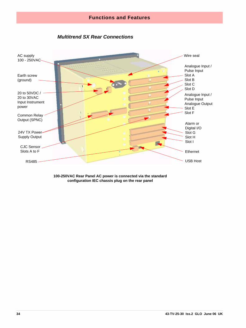
Multitrend SX Rear Connections
Wire seal
Ethernet
Earth screw (ground)
20 to 50VDC / 20 to 30VAC Input Instrument power
Analogue Input /Pulse InputSlot ASlot BSlot CSlot DAnalogue Input /Pulse InputAnalogue OutputSlot ESlot F
Alarm or Digital I/O Slot GSlot HSlot I
RS485 USB Host
AC supply 100 - 250VAC
Common Relay Output (SPNC)
24V TX Power Supply Output
100-250VAC Rear Panel AC power is connected via the standard configuration IEC chassis plug on the rear panel
CJC Sensor Slots A to F
34 43-TV-25-30 Iss.2 GLO June 06 UK

Section 4: Recorder Setup
Configuration of the recorder is performed in the Menu screens and the data is displayed inthe Process screens. This section takes you through the Menu system and how to set upyour recorder. See “Section 6: Screen Configuration” on page 119 for information onsetting up screens to display the data.
User Interface ControlAll user actions can be performed via the touch screen using the stylus. All on-screen selec-tion and navigation areas are large enough so the unit can be operated without falsely se-lecting an adjacent option using the stylus provided.
The stylus is to be used to operate the touch screen. It has a rounded end to avoid damageto the screen. Only a light touch is required to activate the screen. Two styluses are providedand there is a special slot at the top of the recorder to slide the stylus in from the right.
Other User Interface ControlAll user actions can be performed using a mouse or keyboard attached to the front or backUSB host port.
Power up1. Menu AccessWhen the recorder is powered up the display will show a splash screen followed by an ini-tialisation screen displaying the default language flag.
The first screen to appear on the recorder is a default process screen with the menu bar atthe top. Select the Menu button to access the menu system to configure the recorder. TheMenu button takes you to the Main Menu.
From the Main Menu you may be required to Log In, if the Password function is active, see“2. Log On/Off” on page 36.
The next configuration required is to set the recorder to the correct local settings, see “3.Local Settings” on page 36.
Access to Main Menu
Figure 4.1 Default process screen
43-TV-25-30 Iss.2 GLO June 06 UK 35

2. Log On/OffIf Password (ESS - Extended Security System, 21CFR) security is active on your recordera password is required to enter the menu system and process screens. Limited access isavailable without logging on.
For ESS recorders only, locate the First Time Password System Setup sheet included inwith your recorder or see “First Time’ Password System Setup” on page 106.
All UsersWhen Log On is required the Log On button will appear in the top right of the Main Menuscreen. The Log On button can be set to switch to auto Log Off at a specified period of time.To Log On select the Log On button at the top right of the Main Menu screen.
• Log On - User is presented with a user name and password entry box. First time user login is “Admin”. No password is required. Access for the first time user is removed once the password system has been configured.
• Log Off - Once the user has logged on, the option in the Main Menu will turn to Log Off, once selected the user is logged off and returned to the current process screen.
First Time Log OnThe first time the system is used a default user name and password is available, the username is “Admin” and will have no password, this is known as the “first time” user. Access tothe first time user is removed once the password system has been configured. The first timeuser is reinstated if the password system is reset.
For more detailed information see “Section 5: Password Security” on page 105.
3. Local SettingsGo from the Main Menu to Configure > Setup > Edit > General > Localisation
All text is displayed in the currently selected language. Help system language can be select-ed independently, currently English only available. To configure local settings, languages,time zones, daylight saving, temperature units and mains frequency for input filtering, see“Localisation” on page 69 section.
Log On Button
Log Off Button
36 43-TV-25-30 Iss.2 GLO June 06 UK

Default Time ZoneGo from the Main Menu to Configure > Setup > Edit > General > Localisation > Time Zone
The recorder is set to the default Time Zone for Eastern Time (US, Canada), (GMT -5.00).When the configuration is complete select the Finish button to Commit.
4. Time and Date SettingsGo from the Main Menu to Configure > Settings > Set Time
Set the Recorder Time and Date settings, see “Set Time” on page 83.
When the configuration is complete select the Finish button to Commit.
5. Firmware OptionsGo from the Main Menu to Configure > Setup > Edit > General > Factory > Credits
Check your recorder has been set up with the correct amount of credits, displayed as anumber against the Credits item in the menu. Then select the Options item in the Creditsmenu and enable the firmware options you require by changing the cross to a tick/checksymbol.
When the configuration is complete select the Finish button to Commit, Discard or CommitLater. Select the Back button to return to the previous menu.
Menu PathAs each button is selected in the menu system a menu path will appear at the top of thescreen to enable the user to know where they are in the system. The user can select thesebuttons to return to previous menus and enables the user to jump back more than one menuat a time.
Help
Help is available on all menu screens and is context sensitive from each screen. The Helpicon will reside either in the top right or bottom right on all menu screens. All the Help fileshave a Home button that will take you to the Help System main index. Navigating in the helpdoes not stop the logging.
Menu path. Select to go back to previous menus
A grey arrows indicatesa further sub menu
43-TV-25-30 Iss.2 GLO June 06 UK 37

Main Menu
• Configure - Configure the recorder through the Setup, Layout and Pass-words menus. See “Configure Menu” on page 39
• Alarms - Displays the current alarm status. Alarm configuration and theirassociated condition. See “Alarms Menu” on page 85
• Screen - The Screen Menu an Edit button to configure Pen/Channel map-ping, Replay previous data, Screen List to change the screen currentlybeing displayed and Clean Screen facility. See “Screen Menu” onpage 86
• Batch - The Batch function manages sections of data. Batch markers areconfigured by the user and are used to identify and analyse batches ofdata. See “Batch Setup/Batch Control” on page 87
• Recording - Display the current recording status of the unit and allowsrecording control. See “Recording Menu” on page 90
• Messages - Displays all or specified message types. See “MessagesMenu” on page 92
• Process - Controls for any process in use eg. Max/Mins or Totals can becontrolled from this screen See “Process Menu” on page 95
• Status - Displays status information screens that are available to the user,these will provide information for reporting and diagnostic purposes. See“Status Menu” on page 96
• Finish - When an operation is complete use the Finish button to Commit,Discard or Commit Later. See “Finish” on page 104
• Help - The Help icon appears as a question mark on all menu screens. TheHelp files are context sensitive and will supply information for each menuscreen where the icon appears. See “Help” on page 37
Select a button to take you to the next menu
38 43-TV-25-30 Iss.2 GLO June 06 UK

Configure Menu(Main Menu > Configure >)
The Configure screen gives access to the Setup, Layout, Password menus and Settings(Time and Date). The majority of the recorder configuration is done in the Setup menus.
• Setup - In the Setup menu the user can configure how the recorderacquires, stores and actions data. The Edit Setup gives access to sub-menus for Field IO, Pens, Comms, Recording and for General recorder setup. See “Edit Setup” on page 41
• Layout - The user can configure how the data is presented on the screen.From the Layouts screen choose to Edit, Saved or Load layouts in therecorder. See “Layout” on page 78
• Passwords - Manages the security and access to full password configura-tion that allows restricted access within the recorder, providing passwordprotection at different levels. Administrate, Load and Save passwords fromthis menu. See “Passwords” on page 80
• Settings - Recorder settings such as Set Time to configure the recorder'stime and date. See “Settings” on page 83.
Select a button to take you to the next menu
43-TV-25-30 Iss.2 GLO June 06 UK 39

Setup Menu(Main Menu > Configure > Setup)
In the Setup menu the user can configure how the recorder acquires, stores and actions da-ta. The Setup screen gives access to the Edit menu where the majority of the recorder con-figuration is done, also Save and Load setups from this screen.
Edit Setup(Main Menu > Configure > Setup > Edit Setup)
The Edit Setup gives access to sub-menus for Field IO, Pens, Comms, Recording and forGeneral recorder set up. See “Edit Setup” on page 41.
Save Setup(Main Menu > Configure > Setup > Save)
The Save button will produce a list of destinations to save the set up to.
The Compact Flash and the front USB device port are found under the front flap on the re-corder. There is another USB port at the rear of the recorder. The first USB device fitted willbe USB1, therefore the second USB device fitted is USB2.
Load Setup(Main Menu > Configure > Setup > Layout)
Setups can be loaded from Compact Flash or USB key. The Load button will produce a listof source files to load setups from.
The Compact Flash and the front USB device port are found under the front flap on the re-corder. There is another USB port at the rear of the recorder. The first USB device fitted willbe USB1, therefore the second USB device fitted is USB2.
Back ButtonTakes you back to the previous menu
40 43-TV-25-30 Iss.2 GLO June 06 UK

Edit Setup(Main Menu > Configure > Setup > Edit Setup)
Edit Setup will access the main configuration of the recorder through further sub-menus for:Field IO, Pens, Comms, Events, General and Screen recorder set up.
The Edit button may display a warning message if the Commit Later option has been select-ed This means changes to the configuration have been made but the changes have notbeen committed to the recorder. See “Commit Later” on page 104.
• Field IO - This button displays a sub menu containing Analogue In, Ana-logue Out, Alarm/Digital IO and Pulse Inputs card menus. See “Field IOMenu” on page 42
• Pens - This button displays all the configuration areas for setting up Pensincluding Scales, Maths, Alarms, Logging and Totalisers. See “PensMenu” on page 51
• Comms - This button displays a sub menu containing Protocols, Web,SNTP and TCP/IP menus. See “Comms Menu” on page 61
• Events - Events is a firmware option that can be activated using the creditsystem. Events are certain conditions or operations which can be set upand logged according to the time and date of the occurrence. Subsequentlyevents can be reviewed in a list or represented on a graph. See “EventsMenu” on page 66.
• General - This button displays a sub menu containing general recorderinformation including Ident, Localisation, Factory, Batch, Printer set up andGroups (Pens) menus. See “General Menu” on page 68
• Screen - This button displays a sub menu containing Screen Saver, Chartspeed and screen Brightness set up. See “Screen Setup” on page 76
Select a button to take you to the next menu
43-TV-25-30 Iss.2 GLO June 06 UK 41

Field IO Menu(Main Menu > Configure > Setup > Edit Setup> Field IO)
Select which type of Field Inputs/Outputs are required for configuration depending on whattype of cards are fitted in the recorder.
• Analogue In - Select this to configure each Analogue Input channel. See“Analogue In Menu” on page 44
• Analogue Out - Select this to configure each Analogue Output channel.See “Analogue Out Menu” on page 46
• Alarm/Digital IO - Select this to configure Relay Alarm Output card or Dig-ital Input/Output card. See “Alarm / Digital IO” on page 47
• Pulse Inputs - Select this to configure each Pulse Input channel. See“Pulse Input” on page 49
Select a button to take you to the next menu
42 43-TV-25-30 Iss.2 GLO June 06 UK

Table 4.1 : Card Positions and Channel Numbers
Minitrend QX
Slot position Card type Channel numbers
Slot A 8 Analogue InPulse Inputs
1 to 81 to 4
Slot B 8 Analogue InPulse Inputs4 Analogue Out
9 to 169 to 129 to 12
Slot G 4 Relay Output 8 Relay/2 Digital In8 Digital Input/Output16 Digital Input/Output
1 to 41 to 81 to 81 to 16
Table 4.2 :
Multitrend SX
Slot position Card type Channel numbers
Slot A 8 Analogue InPulse Input
1 to 81 to 4
Slot B 8 Analogue InPulse Input
9 to 169 to 12
Slot C 8 Analogue InPulse Input
17 to 2417 to 20
Slot D 8 Analogue InPulse Input
25 to 3225 to 28
Slot E 8 Analogue InPulse Input4 Analogue Out
33 to 4033 to 3633 to 36
Slot F 8 Analogue InPulse Input4 Analogue Out
41 to 4841 to 4441 to 44
Slot G 4 Relay Output 8 Relay/2 Digital In8 Digital Input/Output16 Digital Input/Output
1 to 41 to 81 to 81 to 16
Slot H 4 Relay Output 8 Relay/2 Digital In8 Digital Input/Output16 Digital Input/Output
17 to 2017 to 2417 to 2417 to 32
Slot I 4 Relay Output 8 Relay/2 Digital In8 Digital Input/Output16 Digital Input/Output
33 to 3633 to 4033 to 4033 to 48
43-TV-25-30 Iss.2 GLO June 06 UK 43

Analogue In Menu(Main Menu > Configure > Setup > Edit Setup> Field IO > Analogue In)
Press the Analogue In button to display all the analogue inputs available.
Click on individual Analogue In number to set up each channel profile. Each channel has alist of menu items to be configured.
Refer to connection details and “Analogue Input Channel Numbers” on page 15.
.
• Enabled - Toggle On and Off.
• Type - Select this for a list of available Signal Inputs.
• Sample Rate - Select this for a list of available Analogue Input samplespeeds. A Fast Scanning range of 50Hz (20ms) is available as a firmwareoption. See “Firmware Credit System” on page 129.
• Range (Ohms, Volts and Amps only) - Toggle between Preset and UserDefined. The Preset option will make available a list of Range Types orselect User Defined to specify High and Lower Limits.
• Range Type (Ohms, Volts and Amps only) - Only available when Range isset to Preset. Select for a list of available ranges. The factory default rangeis +/-12V. See “User Defined Maximum Input Ranges” on page 170
• Voltage Units (Volts only) - Select Volts or Millivolts.
• High Limit - Available when Range is User Defined. Select and enter thehigh limit value.
• Lower Limit - Available when Range is User Defined. Select and enter thelower limit value.
• RT Type - Only available when Type is set to RT (Resistance Thermome-ter). Select this for a list of available RT types.
The Analogue In screendisplays all the availableAnalogue Input channels.
Each channel displays its’individual settings.
Select a numbered channelto edit the configuration ofeach input
Menu path to current menu
44 43-TV-25-30 Iss.2 GLO June 06 UK

• Burnout Type - Only available when Type is set to TC (Thermocouple).Toggle between Active and Passive. Active means it will send out a currentto the TC. Set to Passive means it takes a reading without sending out acurrent. The T/C is wired differently for Active an Passive Burnout (seeFigure 2.6, “Input signal wiring,” on page 16).
• Show Burnout - Only available when Type is set to TC. Toggle betweenUpscale and Downscale Burnout.
• TC Type - Only available when Type is set to TC. Select this for a list ofavailable TC types.
• CJ Comp - Only available when Type is set to TC. Select this for a list ofavailable CJ Compensation.
• • Int Automatic - Uses the cold junction sensor in the recorder as a variable ref-erence temperature
• • Ext 0 Deg C - Assumes the cold junction is held at 0°C to provide a 0mV refer-ence, external to the recorder
• • Ext with Spec Temp - Uses a reference junction held at a constant tempera-ture. Specify the temperature that the cold junction sensor is to be set at.
• • Ext Input - Use a thermocouple or resistance thermometer from another chan-nel to measure the cold junction sensor
• External Input - Only available when CJ Compensation is set to Ext Input.Select the input required as an external input.
• Use Pen Scale - Toggle On and Off, this is enabled by default. Analogue #defaults to the corresponding Pen #, eg. A1 will default to Pen 1. If youchange A1 to display another pen scale eg.Pen 3, you must go into Pen 3and change the maths to A1. This will ensure that Pen Scale 3 will displayA1 input. With this enabled the Engineering zero and span is the same asthe pen scale. Disable this and the Engineering zero and span will notreflect the pen scale.
• Eng. Span - (Ohms, Volts and Amps only). Only available when not using“Use Pen Scale” option. This is the highest value of the engineering rangeand corresponds to the top of the input range. Select and enter a valueusing the on-screen keyboard.
• Eng. Zero - (Ohms, Volts and Amps only). Only available when not using“Use Pen Scale” option. This is the bottom of the engineering scale andrepresents the bottom of the input scale. Select and enter a value using theon-screen keyboard.
• Units - (Ohms, Volts and Amps only). This is the Units of Measurement foreach input. Select and enter a value. Max 13 characters. For Thermocoupleand Resistance Thermometer units, see “Localisation” on page 69.
• Label - Select and enter a identification label for the input. Select and entera label. Max 15 characters.
43-TV-25-30 Iss.2 GLO June 06 UK 45

• SQRT Extract - (Ohms, Volts and Amps only). Toggle On and Off. Thesquare root extraction in the analogue input is used to linearise a non-linearinput.
• Sensor Comp - Sensor Compensation may be required to improve accu-racy on a sub range. This is an adjustment to the value of the signal inputon each channel, based on the Engineering units settings. See “SensorCompensation” on page 211
• Demo Setup - Only available if there is no Analogue Input card fitted.Examples of various inputs are available without having an actual signalinput coming into the recorder.
• • Demo Type - Select this for a list of available Demo Type inputs.
• • Cycle Time - Enter the Cycle Time, in seconds, of the Demo Input. Select and use the on-screen keyboard.
• • Add Noise - This is to Add Noise to the Demo Input as a percentage value. Select and use the on-screen keyboard.
When the configuration is complete select the Finish button to Commit, Discard or CommitLater. Select the Back button to return to the previous menu.
Analogue Out Menu(Main Menu > Configure > Setup > Edit Setup> Field IO > Analogue Out)
Only available when an Analogue Out card is fitted as an option, 2 or 4 outputs are availableper card.
Refer to connection details and “Analogue Output Channel Numbers” on page 17
Press the Analogue Out button to display all the analogue outputs available. Click on indi-vidual Analogue Out number to set up each channel profile.
• Enabled - Toggle On and Off.
The Analogue Out screendisplays all the availableAnalogue Output channels.
Each channel displays itsindividual settings.
Select a numbered channelto edit the configuration ofeach output
Menu path to current menu
46 43-TV-25-30 Iss.2 GLO June 06 UK

• Allow Overrange - Toggle On and Off. Disabled as default, this will allowthe output signal to go overrange to 21mA, if disabled the maximum is20mA.
• Transmit Pen - Eg. Select a pen to output 4-20 mA loop. This will take thescale value from the pen it is transmitting and convert to 4-20mA output sig-nal. eg if the scale is 0-50% this signal will fit the scale so 4mA = 0% and20mA = 50%. For 0-20mA output signal with the same 0-50% scale, thiswould read 0mA = 0% and 20mA = 50%.
• Output - Select either 4-20mA or 0-20mA.
• Label - Select and enter an identification label. Select and use the on-screen keyboard. Up to 16 characters.
When the configuration is complete select the Finish button to Commit, Discard or CommitLater. Select the Back button to return to the previous menu.
Alarm / Digital IO(Main Menu > Configure > Setup > Edit Setup> Field IO > Alarm/Digital IO)
The Alarm/Digital IO button will display all the digital inputs/outputs available. Click on eachindividual Alarm IO or Digital IO number to set up each channel profile.
Cards available are:
2 types of Alarm Relay cards
• 4 Alarm Relay Output
• 8 Alarm Relay Output with 2 Digital Inputs
2 types of Digital IO cards
• 8 Digital Inputs or Outputs
• 16 Digital Inputs or Outputs
Alarm Relay Card4 Alarm relay output card or 8 Alarm relay Output with 2 Digital Inputs (6 fixed outputs and2 configurable Digital Input or output) cards.
Digital IO CardThere are 8 or 16 Digital channels per card that can be setup as inputs or outputs. The Dig-ital I/O card also has 4 channels that can be set as pulse inputs (channels 1 to 4). The op-erating frequency for pulse inputs on the Digital I/O card is 1kHz max.
To view and log a channel selected as a Pulse input, set up an extra pen with a Maths func-tion of LPULn in Edit Maths in the Pens menu. For more information see “Appendix B:Maths Expressions” on page 183.
For connection details see For connection details See “Alarm Relay Channel Numbers”on page 21
43-TV-25-30 Iss.2 GLO June 06 UK 47

For all cards select an Alarm/Digital # to display the configuration menu. Each Alarm/Digitalhas a list of menu items to be configured.
• Enabled - Toggle On and Off
• Digital Type - Set to Output Relay contact (Power) for the Alarm Relaycards. Toggle between Input and Output or Pulse Input for the Digital IOcard. On the 4 Relay Alarm card, only output type is available. Channels 1to 6 on the 8 Alarm Relay card are outputs, channels 7 & 8 can be eitherinputs or outputs. Note: Pulse Input only available on channels 1 to 4 for slot G, 17 to 20for slot H and 33 to 36 for slot I.
• Output - (Output only). The relay outputs can be set to be either Latched orSingle Pulse. A Latched relay will be maintained in its active state until thetrigger source has returned to a non-alarm state (unless acknowledged).For Single Pulse the relay will go active for a period of time, specified by theuser, then return to a non active state. The time out period remains inde-pendent of the length of time the active state remains. If the output is set toSingle Pulse, when the alarm is activated the signal will display a singlepulse for the duration set. See Pulse Duration. The alarm will trigger againwhen it goes back into an active alarm state.
• Pulse Duration - (Output only). Available when Single Pulse is selected.Specify the pulse length in seconds from 0.1 (100ms) to 6480 (108 min-utes) in 0.1 second increments. Select and enter the pulse length.
• Failsafe - (Output only). Toggles On and Off. Each relay channel can beindependently selected with the fail safe option. This will invert the state of
The Digital IO screen displays all the available channels that can be set up to be digital inputs or outputs.
Each channel displays its individual settings.
Select a numbered channel to edit the con-figuration of each input or output.
Menu path to current menu
Figure 4.2 Example of Digital IO
NOTICEOutputs that are set to Single Pulse should not be used as a part ofa maths expression as it can cause spurious values.
48 43-TV-25-30 Iss.2 GLO June 06 UK

the relay output. With Failsafe Off, normally open (NO) relays have opencontacts when the power is off, and open contacts when there is no activealarm. The contacts will close when an associated alarm goes active. WithFailsafe On, normally open relays have closed contacts when the recorderis powered on and there are no open active alarms, and the contacts openwith an alarm active or when the power is removed. See “Failsafe RelayPositions” on page 172.
• Label - Select and enter an identification label. Up to 16 characters.
• Active Label - (Input and Output only). This is the label that is shown whenan alarm becomes active. Select and enter a label. Not available for PulseInput. Up to 12 characters.
• Inactive Label - (Input and Output only). This is the label that is shownwhen an alarm becomes inactive. Select and enter a label. Not available forPulse Input. Up to 12 characters.
• Report - This will acknowledge the Alarm/Digital IO to a selected destina-tion. Select User message to add the Digital IO occurance to the messageslist only. Select Mark On Chart to display the occurance on a chart and tothe messages list.
When the configuration is complete select the Finish button to Commit, Discard or CommitLater. Select the Back button to return to the previous menu.
Pulse Input(Main Menu > Configure > Setup > Edit Setup> Field IO > Pulse Input)
Only available when a Pulse Input card is fitted as an option. The Pulse Input card operatesup to a frequency of 25kHz max. See “Pulse Input Channel Numbers” on page 19.
If a Pulse input card is fitted in slot A the first 4 pens will display the maths function of HPULnin Edit Maths in the Pens menu as default to display the pulse reading. For more informationsee “Appendix B: Maths Expressions” on page 183.
Press the Pulse Input button to display the available pulse inputs.
The Pulse Input screen displays all the available pulse input channels that can be set up.
Each channel displays its individual settings.
Select a numbered channel to edit the configuration of each Pulse input.
Menu path to current menu
43-TV-25-30 Iss.2 GLO June 06 UK 49

Click on individual Pulse Input number to set up each channel profile.
• Enabled - Toggle On and Off.
• Hertz - Fixed as Frequency Measure (in Hertz).
• Update Rate - Fixed at 1Hz
• Label - Select and enter an identification label for the pulse input. Selectand enter a label. Up to 16 characters.
When the configuration is complete select the Finish button to Commit, Discard or CommitLater. Select the Back button to return to the previous menu.
50 43-TV-25-30 Iss.2 GLO June 06 UK

Pens Menu(Main Menu > Configure > Setup > Edit Setup> Pens)
Select the Pens button to display all the pens available.
Click on individual pen number to set up each pen profile.
• Enabled - Toggle On and Off.
• Tag - Select and use the on-screen keyboard to type in an identifier for thepen. Up to 48 characters.
• Maths Type - Analogue signals may have a mathematical calculation per-formed on them before they are represented as a pen. Basic maths isstandard in all recorders. Full Maths or Math Scripting are options that mustbe activated. See “Options” on page 97
• Edit Math - Edit the Math for this particular pen. For details see “AppendixB: Maths Expressions” on page 183.
• Scale - Select Scale to go to a sub menu to set up the scale parameters.See “Scale Menu” on page 52
• Logging - Select Logging to go to a sub menu to set up the logging config-uration. See “Logging Menu” on page 53
• Alarms - Select Alarms to go to a sub menu to set up the alarm profile.See “Alarms Menu” on page 55
• Totaliser - Select Totaliser to go to a sub menu to set up the totaliser set-tings. See “Totaliser Menu” on page 57
• Group - Groups of pens can be specified and tagged with a group numberto display on the recorder. Select this to display the list of available PenGroups. Select which group you want this pen to be added to.
• Colour - Each Pen has a Default Pen Colour but this can be changed ifrequired. Select and use the colour palette to set the pen colour.
The Pens screen displays all the available pens.
Each pen displays its scale settings.
Select a pen number to edit the setup of each pen including the Scale, Logging, Alarms and Totaliser
Menu path to current menu
43-TV-25-30 Iss.2 GLO June 06 UK 51

• Trace Width - Select and set the Trace Width for this pen when it is dis-played on a chart. The default trace width is 1 with a maximum of 7.
When the configuration is complete select the Finish button to Commit, Discard or CommitLater. Select the Back button to return to the previous menu.
Scale Menu(Main Menu > Configure > Setup > Edit Setup> Pens > Scale)
Individually configure each scale per pen in the scale menu.
Click on Scale to set up each scale profile per pen.
• Units - Scale measurement Units. Select this and enter the units. Up to 16characters.
• Span - This is the highest value of the scale. Select to enter the Spanvalue.
• Zero - This is the bottom of the scale. Select to enter the Zero value.
• Scale Type - Toggle between Linear or Logarithmic (Log).
• Divs Select - Only available with Linear Scale Type. Toggle between Autoor User Defined.
• Major Divs - Only available when Divs Select is set to User Defined. Selectand enter the major division position.
• Minor Divs - Only available when Divs Select is set to User Defined. Selectand enter the minor division position.
• Start Decade - Only available when the Scale Type is set to Log. Selectand enter the start value of the first decade.
Select the Scale button to take you to the Scale menu
Menu path to current menu
52 43-TV-25-30 Iss.2 GLO June 06 UK

• No. Decades - Only available when the Scale Type is set to Log. Selectand enter the number of decades required. Max 99 decades.
• Numb Format - Displays the Notation of the number format, Scientific orNormal.
• • Notation - Toggle between Scientific or Normal number format. The scientific fomat displays the value to the power of 10 shown here. Notice the value has been rounded up..
• • Auto - Toggle Between Automatic number formatting and User Defined.
• • After Decimal - Only available when User Defined is selected. Select and enter the number of decimal places. (up to 15 decimal places)
When this pen setup is complete go back to the Pen # menu and complete the pen setupfor all other pens.
Logging Menu (Main Menu > Configure > Setup > Edit Setup> Pens > Logging)
Click on Logging to set up each logging profile per pen.
• Enabled - Toggles On and Off to activate or de-activate logging for thispen.
• Type - Toggles between Continuous or Fuzzy logging. Continuous logs every value based on the Method chosen (Sample, Aver-age or Max/Min). Fuzzy Logging has been developed as a secure data storage technique
Normal Scientific
Pen Logging can be set to log as Continuous or Fuzzy
Menu path to current menu
43-TV-25-30 Iss.2 GLO June 06 UK 53

which has a self teaching data storage algorithm so the recorder storesdata at a variable rate to match the process being monitored. Fuzzy Log-ging has intelligent resources to enable the most effective and efficient wayof using the scan rate, storage capacity and recording time. See “Appen-dix F: Fuzzy Logging” on page 205
• Rate Units - Set the Units for the logging rate to be displayed. Select andchoose the logging rate units from the drop down menu.
• Rate - This is the speed at which data is required to be logged. If the Millisecond option is selected as the Rate Units for the logging, thena drop down menu of options will appear. When all other Rate Units areselected a keypad will appear for user entry. Fastest rate is 20mS and slow-est is 60 hours.
• Alarm Rate Units - Set the Units for the Alarm logging rate to be displayed.Select and choose the alarm logging rate units from the drop down menu.
• Alarm Rate - This is the new logging rate used when this pen goes into anactive alarm state. To enable this feature to change the logging rate in analarm state, see Change Log in the Alarms menu. If the Millisecond option is selected as the Alarm Rate Units for the log-ging, then a drop down menu of options will appear. When all other AlarmRate Units are selected a keypad will appear for user entry.
• Method - Only available if the logging Type is set to Continuous. Selectfrom a list of Methods. Sample: logs the last sampled reading. Average: logs the average of all the samples taken since the last log. Max/Min: logs the highest and the lowest of the sampled readings since thelast log.
• Align - Only available if the logging Type is set to Continuous. Select andenter a value from the list to align the logging at specified intervals. Thiswill hold the start of logging until the aligned time selected occurs based onthe recorders real time clock.
• Auto Fit - Only available if the logging Type is set to Fuzzy. Toggles On andOff. AutoFit ensures that the last sampled data point is logged before thesignal goes out of the tolerance set in Band 1 or Band 2. When displayedon a graph, the input signal will automatically fit to this last logged point.This gives a better fit for stepped input changes.
• Band 1 % - Only available if the logging Type is set to Fuzzy. This is wherethe tolerance is set for the input signal. Specify, as a percentage of thescale range, the tolerance band allowed above and below the input signal.Select and enter a value.
• Fuzzy Band 2 - Only available if the logging Type is set to Fuzzy. TogglesOn and Off. This is to enable a second tolerance to be set, configure it to beOn to activate. Only used in conjunction with Autofit On, to specify the Band2 %.
54 43-TV-25-30 Iss.2 GLO June 06 UK

• Band 2 % - Only available if the logging Type is set to Fuzzy. This is wherea tighter tolerance can be specified which must be set within the limits ofBand 1. Specify, as a percentage of the scale range, the tolerance bandallowed above and below the input signal. Select and enter a value.
When the setup is complete go back to the Pen # menu and complete the pen setup.
Alarms Menu(Main Menu > Configure > Setup > Edit Setup> Pens > Alarms)
This is for setting up alarms on this pen only. Select the first available alarm eg. Alarm 1 andconfigure each alarm.
When an alarm has been configured an Alarm Marker or Pen Pointer will appear for eachalarm depending on the type of process screen. See “Alarm Markers” on page 125
• Enabled - Select Enable to see a list of ways to enable or disable thealarm. Disable, Enabled Always or Dig Enabled.
• Enabled by Digital - Only available when Enabled is set to Dig Enabled.Select and choose which digital signal(s) will enable this alarm (on this penonly).
• Type - Select this to display a list of different types of Alarms. High, Low,Deviation. Set a High alarm to activate when the signal goes above theAlarm Level, or set a Low alarm to activate when the signal goes below theAlarm Level. Deviation is the how far this pen can deviate from the Ref Penbefore triggering an alarm. See Deviation Level.
• Level - Select and enter a figure at which the alarm is to be triggered.
• Deviation Level - Only available when Alarm Type is set to Deviation.Select and use the numeric keypad to enter the amount of deviation (inengineering units) to a designated pen (Ref Pen) before an alarm is trig-gered.
The Pen Alarms screen displays up 6alarm set points per pen.
Each alarm displays its individualalarm setting.
Select an alarm number to edit thesetup of each alarm
Menu path to current menu
43-TV-25-30 Iss.2 GLO June 06 UK 55

• Ref Pen - Only available when the alarm Type is set to Deviation. Selectand enter the pen that this alarm is referenced to. This works like an actualpen that dynamically tracks a designated pen.
• Tag - Enter a tag or name to identify this alarm. Up to 17 characters.
• Allow Change - If activated this will allow quick configuration changes tothis alarm level from the Alarms > Configure button on the Main Menu. This does not change the original setup.
• Relays Out - Select and choose which Relay Output(s) is triggered by thisalarm (on this pen only). The Fixed button will use the common relay outputon the power board (24V relay).
• Latched - A latched alarm will maintain in its active state until the triggersource has returned to a non-alarm state and the alarm has been acknowl-edged. A latched alarm will continue to flash, if an alarm marker or penpointer is displayed, until it is acknowledged and in a non-alarm state. Nor-mal alarms can also be acknowledged. See “Acknowledging Alarms” onpage 201 A Reflash option is available to keep the alarm flashing whilst inan alarm state even after it has been acknowledged. See Reflash.
• Change Log - Toggles On and Off. Select this to change the Log speedwhen an alarm occurs. The Log rate changes when alarm is active andstays at the alarm rate for as long as the alarm is active then returns to thenormal logging rate. Set up the new alarm logging rate in Alarm Rate in“Logging Menu” on page 53.
• Mark Chart - Toggles On and Off. Selecting On will place a Mark on theChart with automated messages when the alarm becomes active. From theposition of the Mark on Chart the chart background colour will change toshow it is in an alarm state.
• Hysteresis - (not available for Deviation). Toggles On and Off. When this isactivated, you can set a tolerance level for an alarm. It allows a specifedpercentage value of the span of the scale to be added to the alarm level.
• Hyst Level % - (not available for Deviation alarm). Enter as a percentageof the span of the scale. This is how much tolerance the signal can havepast the set alarm activation point until the alarm is de-activated. The exam-ple in Figure 4.3 shows the alarm activating at 40% which is the set lowalarm level. The alarm is not de-activated until the signal is at 50%, which is10% past the set alarm level. So the Hyst Level % would be set to 10%.Reverse the process for a high alarm.
• Damping - Toggles On and Off. Damping is a time delay that works goinginto alarm only. When switched On, the alarm level must be breached for aspecific period of time before an alarm is triggered.
• Damping Time - Set the amount of Damping time in seconds
• Reflash - Toggles On and Off. Activate this to re-enable an active alarmthat has been acknowledged. Set the Reflash Time.
56 43-TV-25-30 Iss.2 GLO June 06 UK

• Reflash Time - Only enabled when Reflash is active. Set the time periodafter the alarm has been acknowledged for the alarm to reflash if it is still inan alarm state.
When the setup is complete go back to the Pen # menu and complete the pen setup.
Totaliser Menu(Main Menu > Configure > Setup > Edit Setup> Pens > Totaliser)
The Totals option must be active to use this option. See Table 7.1, “Firmware Options,”on page 129.
The Totaliser function is normally associated with flow monitoring applications. The input tothe recorder would be a measure of flow rate (eg. In litres per second) and the total amountthat has flowed over a specified time period. Multiple totalisations are possible with the useof extra pens (firmware Credit option). Totalisation values are 10 digits plus exponent.
Select Totaliser from the Pen screen to display the totalising setup menu.
50%40%
0%
100%
Low Alarm Level
10% Hysteresis level
Alarm de-activated at this point
Alarm activated at this point
Figure 4.3 Hysteresis Level
Menu path to current menu
Totaliser menus showing Normal and Sterilisation types
43-TV-25-30 Iss.2 GLO June 06 UK 57

Click on Totaliser to set up the totalising profile per pen.
• Enabled - Toggles On and Off to activate or de-activate totalising for thispen.
• Type - Select this for a list of Types of totalising. Normal or Sterilisation.Normal totaliser function is usually associated with flow monitoring applica-tions. Sterilisation* is where items are subjected to heat over a period of time.Each pen can be totalised according to the Fo or Po sterilisation* functionat 250 °F (121.11°C). The Standard Reference Temperature and ThermalResistance (Z Value) are adjustable. All temperature limits are adjustable.Start temp, Reference temp and Z factor are all user defined, allowing sup-port for many different types of sterilisation applications. See “Sterilisa-tion” on page 59
• Tag - Select and enter an identifier for the pen. Up to 17 characters.
• Add to Msgs - Toggles On and Off. Select this to add a totaliser to themessages screen. Eg. Total1: Total 1 Reset
• Units - Normal Totaliser only. This is the Units of Measurement for the total-iser. Select and enter the units. Up to 12 characters.
• Time Factor - Normal Totaliser only. The normal totaliser units are dividedby the time factor.
• Unit Factor - Normal Totaliser only. This is the totalising factor for the con-version from pen input units to a totaliser value. The normal totaliser unitsare multiplied by the unit factor.
• No Backflow - Normal Totaliser only. If the flow reading should go into anegative value, eg. The flow meter has been switched off, and “No Back-flow” is inactive, the totaliser will subtract from the total value. When “NoBackflow” is active any negative values are ignored and the total value isheld while the flow meter is off until the backflow level is exceeded.
• Backflow Level - Only active when No Backflow is set. Set the level atwhich totalising will stop if the signal flow goes below this limit and if the NoBackflow option is active.
• Restrict Range - Normal Totaliser only. Toggles On and Off. When activethe totaliser restarts at Min range once it reaches Max range.
• Min. Range - Normal Totaliser only. Only available when Restrict Range isactive. Select and enter the minimum limit for the totals to range to.
• Max. Range - Normal Totaliser only. Only available when Restrict Range isactive. Select and enter the maximum limit for the totals to range from.
• Use Remainder - Normal Totaliser only. Only available when RestrictRange is active. Toggles On and Off. If the total exceeds the maximum range set, the total will reset to the mini-
58 43-TV-25-30 Iss.2 GLO June 06 UK

mum range set. When Use Remainder is active, it will carry over anyamount in excess of the maximum range set.
• Temp Input Units - For Sterilisation, select the temperature input units.
• Start Temp - For Sterilisation, select the Start Temperature.
• Ref. Temp - For Sterilisation, select the Reference Temperature.
• Z Factor Temp - For Sterilisation, select the Z factor temperature
• Include Cooling - For Sterilisation, Include Cooling if required
• Completion Value - For Sterilisation, if cooling is not required, enter aCompletion Value. The totaliser will stop at this value.
• Numb Format - Displays the Notation of the number format, Scientific orNormal.
• • Notation - Toggle between Scientific or Normal number format.
• • Auto - Toggle Between Automatic number formatting and User Defined.
• After Decimal - Only available when User Defined is selected. Select and enter thenumber of decimal places. (up to 15 decimal places)
When the setup is complete go back to the Pen # menu and complete the pen setup.
Sterilisation*Specification for Sterilisation. The definition Fo/Po is the sterilisation/pasteurisation time inminutes required to destroy a stated number of organisms with a known z at temperature T.For example, "F18/250" represents the time in minutes required to destroy a stated numberof organisms at a temperature of 250F (121.11C) with a z = 18 degrees F. F values are usedto compare the sterilizing values of different processes, however, F values cannot be com-pared unless the z values are the same. When temperature is not specified (for example, F= 8.6) it is understood that the temperature is 250F (121.11C); the subscript O (as in theterm Fo = 7.4) is used to indicate that the z = 18 degrees F and the temperature is 250F(121.11C)
Displaying TotalsTotals can be displayed by setting up a separate pen to display the totalised value. Totalsare best displayed in a DPM screen. If you use a separate pen to display a total be awarethat if the total is stopped the pause symbol will not appear as it does for a totaliser pen.
First, select a pen you are going to use to display the total of another pen. Extra pens areavailable as a Firmware option see “Credits” on page 70). For this example this will be Pen4.
In the pens menu for the totalising pen (Pen 4), select Edit Maths and enter “T” followed bythe pen number you wish to totalise eg.T3. Pen 4 is now set to totalise the value of Pen 3.
It may be necessary to set a larger scale for the totalising pen (pen 4) as the totalising valuemay become larger than the pen scale of the pen being totalised (pen 3).
When the configuration is complete select the Finish button to Commit, Discard or CommitLater. Select the Back button to return to the previous menu.
43-TV-25-30 Iss.2 GLO June 06 UK 59

Go to the recorder’s process screen and select a screen showing DPMs. The totalising pen(pen 4) will display the totalising value of pen 3.
60 43-TV-25-30 Iss.2 GLO June 06 UK

Comms Menu(Main Menu > Configure > Setup > Edit Setup> Comms)
Standard Communication InterfacesRear Ethernet Communication Port
The rear of the recorder is fitted with an Ethernet10/100 port and RS485 port, which sup-ports:
• RS485 Modbus protocol and TCP/IP Modbus
• Web Browser. See “Web” on page 63
• OPC Server connectivity to third party software. OPC Server connection must be enabled by selecting the OPC option in “Credits” on page 70. For more details on OPC Servers see “OPC Interface - Open Process Control” on page 140
Rear RS485 Port
• RS485: 2 wire to support Modbus RTU.
This can be supported as a separate communications module that plugs into the back of the recorder. This is a Master-Slave system where the recorders are slave devices
Front and Rear USB Communication PortsThe front and rear of the recorder is fitted with a USB communication port.
The USB Host ports will provide an interface for:
• Data downloads.
• Setup uploads.
• External keyboard & mouse
• Barcode reader
• Mass storage device (USB key)
43-TV-25-30 Iss.2 GLO June 06 UK 61

• Modbus - Modbus can be used with RS485 or Ethernet ports. See “Mod-bus” on page 62
• Web - Enables web access to view the recorder web page. See “Web” onpage 63
• SNTP - Simple Network Time Protocols. See “SNTP” on page 63
• TCP/IP - Transmission Control Protocol / Internet Protocol. See “TCP/IP”on page 64
Modbus(Main Menu > Configure > Setup > Edit Setup> Comms > Modbus)
Modbus can be used with RS485 or Ethernet ports. The Modbus protocol defines a mes-sage structure that controllers will recognise and use, regardless of the type of network overwhich they can communicate.
• Enabled - Toggle On and Off
• Port - Select this for a list of available Protocols, either Ethernet or RS485.For port configuration see “Ports” on page 65
• Protocol - Select this for a list of available ports. Modbus or Modbus X*.Modbus and Modbus X can both use Ethernet or RS485 Ports. Protocolsdefine the format in which the data is transferred from the recorder to a PCor transfer between other devices and peripherals.
• Slave ID - This is a unique Modbus ID/Address used by the recorder toidentify Modbus messages. Applications that talk to the recorder with Mod-bus will need to know this number to return messages to the device. If youare using the Communication Server of Trend Server Pro the samenumber must match.
• Baud Rate - (Only available when the RS485 port in selected). Select thisfor a list of available Baud Rates. This is the speed, in bps (bits per sec-ond), at which data is transferred.
• Byte Options - (Only available when the RS485 port is selected). Selectthis button for a list of available Byte Options. The Byte Options consist of 3digits comprising of Parity (set to None N, Even E or Odd O), 8 Data Bitsand Stop Bits, signifying the end of the character string, 1 or 2,
• Line Turn Around - Only available when the RS485 port in selected). Thisis for a 2-wire line type. Data has to be fully transmitted before the line canbe turned-around and data can be received, or vice versa.
• Reply Delay - Enter a delay time, in milli seconds, before the recordersends a reply. Recommended delay should be set to 12mS (min.) if usingthe Comms Server.
*Modbus X - Modbus X protocol differs from standard Modbus by the 4 floating point orderthat is reversed for application compatibility.
When the configuration is complete select the Finish button to Commit, Discard or CommitLater. Select the Back button to return to the previous menu.
62 43-TV-25-30 Iss.2 GLO June 06 UK

Web(Main Menu > Configure > Setup > Edit Setup > Comms > Web)
The Web browse function is enabled/disabled from the recorder. Select this to enable andallow the recorder to be browsed on a web page. Internet access is required. The Web but-ton is password protected if passwords are enabled. For web browsing information see“Web Browser” on page 142 and “Internet Security Settings” on page 142.
“Level Permissions” on page 109 for information on permission levels to the Web Brows-er and access within the web page for Full Remote Control.
SNTP(Main Menu > Configure > Setup > Edit Setup > Comms > SNTP)
Simple Network Time Protocols is a protocol for synchronising the clock on the recorder witha Network Server.
• Server Enable - Toggle On and Off. Activate this to make this recorder theserver. Other recorders, set up as clients, can synchronise their time to thisserver recorder.
• Client Enable - Toggle On and Off. Activate this to set this recorder to syn-chronise time with the server. See Figure 4.4 on page 64.
• Server Name - Only available when Client Enable is active. This is thename of the Network Server that can be used for time synchronisation.Enter the server name to be used for time synchronisation (this could be aTime Server on the internet or on your network). If a recorder is acting asthe Server, the Client recorders must have the recorder’s name as theServer Name (up to 32 characters). See “Ident” on page 69 for therecorder’s name.
• Period - Only available when Client Enable is active. Select and enter thetime period in seconds required between checking and updating the timeusing the on-screen keyboard. This will default to 120 seconds.
• Threshold - Only available when Client Enable is active. This is a specifiedamount of time (in seconds) that the recorder clock must be within toensure synchronisation with the network server. Eg. if set to 3600 therecorder time must be within 1 hour of the network server to ensure timesync will take place.
43-TV-25-30 Iss.2 GLO June 06 UK 63

Client/Server NetworkFigure 4.4 on page 64 shows a Network Server at the top, a recorder acting as both aserver and a client in the middle and a string of client recorders at the bottom. A recordercan be set up to be a server and a client. Setting it as both means this recorder will synchro-nise time with the network server. But will also allow other recorders to time sync with it. Thissaves many recorders trying to time sync with the network server.
When the configuration is complete select the Finish button to Commit, Discard or CommitLater. Select the Back button to return to the previous menu.
TCP/IP(Main Menu > Configure > Setup > Edit Setup > Comms > TCP/IP)
Transmission Control Protocol/Internet Protocol.
A protocol for communication between computers, recorders and other devices.
• Static IP - Toggle On and Off. This is an IP address which is the sameevery time.
• IP Address - (Available when Static IP is On). This is an identificationaddress for communications between two peripherals. The IP Addressidentifies a specific recorder or device. Select and enter a valid IP address.
• Sub Net Mask - (Available when Static IP is On). Acts as a filter when iden-tifying an IP address
• Gateway - (Available when Static IP is On). A configuration parametertransmitted to each network device
• DNS/WINS/MDNS - Set to Automatic, click on this to activate and de-acti-vate options. DNS = Domain Name System, WINS = Windows InternetName Service, MDNS = Managed Data Network Services. See “DNS/WINS/MDNS” on page 65
Figure 4.4 Client/Server network
64 43-TV-25-30 Iss.2 GLO June 06 UK

• Ports - The Port numbers are associated with the IT system in use. Portnumbers are set to a default but can be changed by the user to allow datatraffic to use a specified port. See “Ports” on page 65
When the configuration is complete select the Finish button to Commit, Discard or CommitLater. Select the Back button to return to the previous menu.
DNS/WINS/MDNS
(Main Menu > Configure > Setup > Edit Setup > Comms > TCP/IP > DNS/WINS/MDNS)Set to Automatic, click on this to activate and de-activate options. DNS = Domain Name Sys-tem, WINS = Windows Internet Name Service, MDNS = Managed Data Network Services.
• Auto DNS - This is a sub menu for DNS/WINS/MDNS. Toggles On and Off.
• Pri. DNS Address - This is a sub menu for DNS/WINS/MDNS. Only availa-ble when Auto DNS is deactivated.
• Sec. DNS Address - This is a sub menu for DNS/WINS/MDNS. Only avail-able when Auto DNS is deactivated.
• Auto WINS - This is a sub menu for DNS/WINS/MDNS. Toggles On andOff.
• Pri. WINS Address - This is a sub menu for DNS/WINS/MDNS. Only avail-able when Auto WINS is deactivated.
• Sec. WINS Address - This is a sub menu for DNS/WINS/MDNS. Onlyavailable when Auto WINS is deactivated.
• Auto MDNS - This is a sub menu for DNS/WINS/MDNS. Toggles On andOff.
When the setup is complete go back to the TCP/IP menu and complete the Comms setup.
Ports(Main Menu > Configure > Setup > Edit Setup > Comms > TCP/IP > Ports)
The port numbers are associated with the IT system in use. Port numbers are set to a defaultbut can be changed by the user to allow data traffic to use a specified port.
• HTTP - HyperText Transport Protocol is the communications protocol thatenables Web browsing. Select and enter the desired port number ifrequired.
• FTP Data – File Transfer Protocol port for transferring data. Select andenter the desired port number if required.
• FTP Control – File Transfer Protocol. Select and enter the desired portnumber if required.
• Modbus - communications protocol used for automation applications.Select and enter the desired port number if required.
When the setup is complete go back to the TCP/IP menu and complete the Comms setup.
43-TV-25-30 Iss.2 GLO June 06 UK 65

Events Menu(Main Menu > Configure > Setup > Edit Setup > Events)
Events is a firmware option that can be activated using the credit system.
Events are certain conditions or operations which can be set up and logged according to thetime and date of the occurrence. Subsequently events can be reviewed in a list or represent-ed on a graph. An event is made up from a Cause and an Effect. Set up a cause such asPen 1 going into an alarm state and the effect of this could be to start a totaliser or acknowl-edge the alarm.
Select the first available event eg. Event 1. In the Event 1 menu tick to enable and changethe Event tag if required. Each Event has two Causes and two Effects available, these canbe used in different combinations:
• An event can have two causes that triggers just one effect eg. A pen going into alarm and a Totaliser starts, this could have the effect of starting Logging.
• An event can have one cause that has two effects, eg. A pen could go into alarm and the effects could be that the alarm is acknowledged and a Totaliser is started. See “Event 1 example:” on page 67.
• An event can have two causes that have two effects, eg. A pen goes into alarm and a Total-isers is started, the effects could be the alarm is acknowledged and a mark on chart is dis-played to show the start of the totaliser
When selecting Totalisers and Alarms etc. ensure they are enabled and configured in thePens menu.
Table 4.3, “Events - Cause and Effect,” on page 68 for a full list of Causes and Effects.
NOTICERemember that either Cause 1 OR Cause 2 will trigger Effect 1 AND Effect 2. Cause 1 and Effect 1 are not linked, just as Cause 2 and Effect 2 are not linked
66 43-TV-25-30 Iss.2 GLO June 06 UK

Event 1 example: Adding Cause 1
Event 1 example: Adding Effect 2
Event 1 example: Adding Effect 1
Select which Pen numberand which alarm on thatpen, will have the alarmacknowledged.
Figure 4.5 Event 1 example:
43-TV-25-30 Iss.2 GLO June 06 UK 67
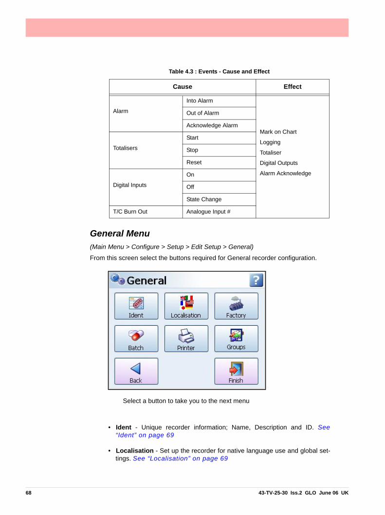
General Menu(Main Menu > Configure > Setup > Edit Setup > General)
From this screen select the buttons required for General recorder configuration.
• Ident - Unique recorder information; Name, Description and ID. See“Ident” on page 69
• Localisation - Set up the recorder for native language use and global set-tings. See “Localisation” on page 69
Table 4.3 : Events - Cause and Effect
Cause Effect
Alarm
Into Alarm
Mark on Chart
Logging
Totaliser
Digital Outputs
Alarm Acknowledge
Out of Alarm
Acknowledge Alarm
Totalisers
Start
Stop
Reset
Digital Inputs
On
Off
State Change
T/C Burn Out Analogue Input #
Select a button to take you to the next menu
68 43-TV-25-30 Iss.2 GLO June 06 UK

• Factory - This menu contains Credits (for activating recorder options),Firmware Upgrade, Calibration, Demo Traces, Reset Setup and Produc-tion. See “Factory” on page 70
• Batch - The Batch menu is for entering the Batch requirements for startinga new batch, including using a Barcode reader. “Batch Menu” onpage 74.
• Printer - The Printer menu allows configuration for setting up a printer. See“Printer Menu” on page 75.
• Groups - Groups of Pens can be specified and named with a Group nameor number. See “Groups” on page 75.
When the configuration is complete select the Finish button to Commit, Discard or CommitLater. Select the Back button to return to the previous menu.
Ident(Main Menu > Configure > Setup > Edit Setup> General > Ident)
Unique recorder information.
• Name - Enter the recorder’s name. Maximum characters 32
• Description - Enter a description for the recorder using the on-screen key-board. Maximum characters 64
• ID - This is a unique 4 digit identifier specific to this recorder.
When the configuration is complete select the Finish button to Commit, Discard or CommitLater. Select the Back button to return to the previous menu.
Localisation(Main Menu > Configure > Setup > Edit Setup > General > Localisation)
Set up the recorder for native language use and global settings including:
• Language - Select native language menu prompts from list.
• Help Language - Select native language for Help Files, currently Englishonly available.
• Time Zone - Select the corresponding time zone from the drop down list.
• Daylight Saving - Toggle On or Off to activate daylight saving, if applica-ble. When the time zone is selected and daylight saving is active therecorder will change the daylight saving hour automatically. The date thisoccures depends on the time zone selected. Some time zones do not havedaylight saving. Data being recorded will be affected, either with a 1 hourgap of data or a 1 hour overlap of data.
• Temp.Units - Select the Temperature Units that the recorder is set to fortemperature measurement. Pen scale units may need to be changedaccordingly. See Pen Scale.
43-TV-25-30 Iss.2 GLO June 06 UK 69

• Line Hz – Toggle between 50Hz or 60Hz. Mains power frequency. Used tooptimise analogue input filtering. Note: The default value is set based onthe model number but can be changed here.
When the configuration is complete select the Finish button to Commit, Discard or CommitLater. Select the Back button to return to the previous menu.
Factory(Main Menu > Configure > Setup > Edit Setup> General > Factory)
The Factory menu contains information on the Firmware Credit System, Upgrading the re-corder Firmware, CJC and Analogue Input Card Calibration, Demo Traces, Reset Setupfunction and a Production only menu.
• Credits - The Credit menu contains the Serial no. of the recorder, how many credits are available, displays the Options Code and lists what Firmware Options are currently active. See “Credits” on page 70
• FW Upgrade - The Firmware Upgrade button allows new versions of the recorder firmware to be loaded into the recorder. See “FW Upgrade” on page 71
• Calibration - Analogue In and CJC Calibration can be performed per slot (card). See “Calibration” on page 71
• Demo Traces - A set of demo traces are available for demonstration or simulation pur-poses. See “Demo Traces” on page 73
• Reset Setup - Select this to clear the current setup. A Warning message will appear before activating the reset. See “Reset Setup” on page 74.
• Delete All Data - This button will delete all data from the internal memory.
When the configuration is complete select the Finish button to Commit, Discard or CommitLater. Select the Back button to return to the previous menu.
Credits(Configure > Setup > Edit Setup> General > Factory > Credits)
70 43-TV-25-30 Iss.2 GLO June 06 UK

The Credit menu contains the Serial No. of the recorder, how may credits are available, dis-plays the Options Code and lists what Firmware Options are currently active.
• Serial No. - read only and cannot be edited.
• Credits - read only and cannot be edited. It displays the number of Credits available to activate additional firmware functionality.
• Options Code - The Options code is a unique coded number for this recorder that contains information that enables certain functionality including the total credit value.
• Options - This displays how many credits are currently in use. Select this to produce a list of Firmware options available and their credit values. Toggle each option On or Off to ena-ble the feature within the recorder. If there are not enough credits available. More credits are available from your supplier. For a complete lists of all the firmware options and their functionality see Table 7.1, “Firmware Options,” on page 129
FW Upgrade (Configure > Setup > Edit Setup> General > Factory > FW Upgrade
The Firmware Upgrade button allows new versions of the recorder firmware to be loadedinto the recorder via a USB key or a Compact Flash card. The file type required to upgradethe Firmware has the file extension .xsu. Firmware can be upgraded from the web site atwww.XSeries-info.net.
Insert the Compact Flash or USB key with the latest revision of Firmware (.xsu file format)and press the FW Upgrade button. The recorder will scan and check the files on the externaldevice with the current version running in the recorder. Any later version files on the externaldevice are copied into the recorder.
See “Storage Media Format” on page 90 for formatting information of Compact Flashcards and USB keys.
To check the firmware upgrade has been successful, see the Status Menu, “General” onpage 97.
Calibration(Configure > Setup > Edit Setup> General > Factory > Calibration)
Cards will be calibrated in the factory. All ranges are factory calibrated and set to the defaultrange of +/-12V.
Date & Type of last calibration is stored in “Maintenance” on page 99.
Analogue In and CJC Calibration can be performed per slot (card). Select the AI or CJC cal-ibration button to go to the next menu.
AI CalibrationIn this menu there is a button for each Analogue Input card fitted in the recorder. Calibrationis done per channel.
Cards may be reset to original ‘factory’ cal, i.e. a card holds two sets of calibration constants(factory & user) for all ranges.
Factory Cal - The recorder is calibrated in the factory. These are pre-stored calibration val-ues that cannot be changed by the user. If the recorder is re-calibrated to a User Cal thefactory values can be restored at any time.
User Cal - User calibration can be applied at any time. To meet the accuracy values spec-ified (see “Input Range Performance Accuracy Table” on page 177.), calibrationsource should be accurate to 0.01% full scale or better.
43-TV-25-30 Iss.2 GLO June 06 UK 71

On initial power up the Factory Cal and the User Cal are the same.
The AI Calibration menu displays a button for each Analogue Input card fitted.
• Select the desired slot button and select the Range required to be calibrated from the drop down list eg.+/-50V.
• Each card has channels numbered 1 to 8. Underneath each channel is the type of calibra-tion.
• Select the button below the corresponding channel number and select the type of calibration from the list, in this case Recalibrate. The Recalibrate icon will appear under that channel.
• The Calibration Positive Range box appears with instructions to connect the top limit of the input range. Once this is done press the Calibrate button. Next, the Calibration Negative Range box appears instructing the user to apply the bottom range limit. When this is done press the Calibrate button.
• When the calibration is complete the icon changes to the User cal icon under the channel to show that the channel is using the user cal.
Table 4.4 : Analogue In Calibration
Calibration Type
Factory
User
Recalibrate
Recalibrate All
Factory All
72 43-TV-25-30 Iss.2 GLO June 06 UK

CJC CalibrationFor Thermocouple Input calibration only.
There is a single CJC sensor for each AI card, but the temperature across the connector willnot be constant. The CJC calibration allows the user to compensate for temperature gradi-ent.
In this menu there is a button for each slot for Cold Junction Calibration. Calibration is per-formed per slot/card.
• Select the desired slot button. If a CJC connector is not fitted a message box will appear.
• The CJC temperature reading is displayed in the CJ Temp column.
• If the known temperature is different to the recorders reading an Offset can be entered to make an adjustment to future values. The Cold Junction temperature should be measured at the point where the thermocouple is connected in the terminal block. Ensure the meas-ured temperature is accurate to within 0.1°C.
• Enter the difference between the CJ Temp on the recorder and the measured reading as the Offset Value. The offset is added to all future readings and displayed in the Calibrated CJ Temp column.
• The Measured Temp column will display the actual temperature using the Calibrated CJC Temp, on channels with T/C fitted. For more details of how a thermocouple works, refer to “Appendix C: Thermocouple Connections” on page 197.
• Select the tick box to go back and the Finish button to Commit, Discard or Commit Later.
Demo Traces(Configure > Setup > Edit Setup> General > Factory > Demo Traces)
A set of demo traces available for demonstration or simulation purposes.
Options for each demo trace are:
• No Simulation - Demo traces are deactivated and no simulation traces are availa-ble.
• Simulate if board not fitted - Simulation is activated when an Analogue In card is not fitted in one of the top two slot positions.
43-TV-25-30 Iss.2 GLO June 06 UK 73

Reset Setup(Configure > Setup > Edit Setup> General > Factory > Reset Setup)
This will remove the current setup from the recorder and return to the default setup. Whenyou select this button the “Reset Setup Warning” box will appear with a message: “Are yousure you want to clear your current setup? This is an irreversible and will re-start therecorder”. Select OK to reset the setup or Cancel to ignore and return to the Factory menu.
Delete All Data(Configure > Setup > Edit Setup> General > Factory > Delete All Data)This button will delete all data from the internal memory. When you select this button the “Delete DataWarning ” box will appear with a message: “This will delete ALL log and chart data, taking 80 sec-onds to complete and will restart during the process”. 80 seconds is an approximate time depend-ing on the size of the internal memory. Select OK to proceed. This is an irreversible procedure.
Batch Menu(Configure > Setup > Edit Setup> General > Batch))
Batch is a firmware option which can be activated from “Credits” on page 70.
The Batch function allows the user to segment portions of data for further analysis. Settingup a batch requires information to identify and control batches of data. Batch data can alsobe paused, for viewing, and resumed. A batch can be aborted at any time, if so this will notregister as a batch, a batch is only complete when it has been stopped.
In this menu the user can stipulate which items are required when setting up a new batch.A marker will appear for each item activated on this menu and will be placed on a chart. Formore details on batch Markers, refer to “Batch Setup/Batch Control” on page 87.
Toggle the batch menu options On or Off.
• User ID Required - Tick to make this a requirement when starting a new batch. If Pass-words are active on the recorder then the User ID page will be skipped for user entry and will be automatically entered.
• Description Required - Tick to make this a requirement when starting a new batch
74 43-TV-25-30 Iss.2 GLO June 06 UK

• Comment Required - Tick to make this a requirement when starting a new batch
• Lot Required - Tick to make this a requirement when starting a new batch
• Allow Direct Access - Allows use of a Barcode reader to make entries for all the items listed in this menu.
Barcodes for BatchBatch markers can be created using independent barcode software. The barcodes can
then be read using a barcode wand or reader. Any type of Batch marker can be encodedinto a barcode using the same control characters used to build up a batch marker.
This example shows a barcode encoded to start a batch: //S = Start Batch216 = Batch Name//I = User ID is Fred//C = Comment text is Test
A barcode with up to 25 characters (including spaces) can be read into the recorder usinga USB ASCII barcode reader.
Printer Menu(Configure > Setup > Edit Setup> General > Printer)
The Printer function is a firmware option that is selectable from the Factory menu > “Cred-its” on page 70. The screens that currently can be printed are all the items under the Statusbutton. For more information on these screens see the “Status Menu” on page 96.
The Printer menu allows configuration for setting up a printer. The printer option displays aPrint button from various screens using a basic USB standard PLC printer. For details onsuitable printer types see “Print Support” on page 24.
• Allow Printing - Tick to enable On and Off
Groups(Configure > Setup > Edit Setup> General > Groups)
In the pens menu individual pens can be added into a group. These groups of pens can thenbe displayed on the recorder. The same pen can only be associated in one group. Thismenu is used for re-naming the groups.
43-TV-25-30 Iss.2 GLO June 06 UK 75

Screen MenuScreen Setup
(Main Menu > Configure > Setup > Edit Setup> Screen)
Set up the recorder’s screen configuration.
• Screen Saver - In this menu you can configure the Screen Saver functions. See “Screen Saver” on page 76
• Charts - In this menu you can set the Fast, Medium and Slow chart speeds. See “Charts” on page 77
• Brightness - Adjust the brightness of the screen using the instant brightness slider. See “Brightness” on page 77
Screen Saver(Main Menu > Configure > Setup > Edit Setup> Screen > Screen Saver)
Configure the screen display and Screen Saver functions. The default state for the ScreenSaver is disabled. The Screen Saver function helps to reduce backlight wear. When active,the back light is off and nothing on the display is visible. The screen saver will not functionin Setup Menus or in test mode.
• Enabled - Toggle On and Off.
• Timeout - Only available when the Screen Saver function is active. This ishow long the Screen Saver will display on the screen. Programmablebetween 1 and 720 minutes in software, when disabled the screen willremain on permanently (enter 0 to disable).
• Saver Type - Only available when the Screen Saver function is active. Thisis set to Normal.
76 43-TV-25-30 Iss.2 GLO June 06 UK

• Dim Saver - Only available when the Screen Saver function is active. DimSaver will help to increase the life of the backlight and lower the screenbrightness for night time use. Use Saver Brightness or Off Always.
• Saver Level - Only available when the Dim Saver function is set to UseSaver Brightness. Select this to use the instant dimming slider which lowersthe screen brightness. Default screen brightness is 80%. Adjustablebetween 10% and 100% of full brightness.This works on a square law rule that means if you reduce the saver level by25% you will double the backlight life. If you reduce the saver level by 50%you will quadruple the backlight life. Normal backlight MTBF at 100%brightness is 55,000 hours for the QX and 43,000 hours for the SXrecorder.
When the configuration is complete select the Finish button to Commit, Discard or CommitLater. Select the Back button to return to the previous menu.
Exit Screen SaverIf the screen saver is active, any of the following will deactivate the screen saver,
• User touches screen.
• Any USB device is plugged in or unplugged.
• On alarm - An alarm is triggered, the unit will not return to screen saver till the alarm state is inactive and another screen saver time-out period has expired.
Charts(Main Menu > Configure > Setup > Edit Setup> Screen > Charts)
A Chart speed is the time it takes the data to travel from one side of the screen to the other.The recorder has up to 10 different chart speeds. There are 3 categories that can be set;Slow, Medium and Fast (default). Set up each category to display the desired chart speed.Limits are in place so that each speed cannot overlap. Eg. a Medium speed cannot be setfaster than the Fast speed.
When complete go to Finish > Commit to implement the new set up.
• Fast Speed – 600mm/h to 6000mm/h
• Medium Speed - 20mm/h to 120mm/h
• Slow Speed – 1mm/h to 10mm/h
Once the charts speeds have been set up in this menu go to a process screen displayingdata on a chart and touch the screen. This will activate the Settings menu in the top right ofthe screen, select this to display the 3 categories set. See “Chart Speeds” on page 124.
Brightness(Main Menu > Configure > Setup > Edit Setup> Screen > Brightness)
Set the recorders screen brightness using the instant brightness slider.
Default screen brightness is 80%. Adjustable between 10% and 100% of full brightness.
Set the brightness level, tick to agree, then go to Finish, Commit to permanently apply thechange.
43-TV-25-30 Iss.2 GLO June 06 UK 77

Layout(Main Menu > Configure > Layout >)
The user can configure how the data is presented on the screen. From the Layouts screenchoose to Edit, Save or Load layouts in the recorder.
Edit Layout(Main Menu > Configure > Layout > Edit)
This section allows the user to configure and customise the standard screens on the record-er. The Edit button will produce a list of available screens in the recorder. In each screen youcan enable, check and change the screen properties. See “Edit, Screen Properties” onpage 121.
The Edit button may display a warning message if the Commit Later option has been select-ed. This means changes to the configuration have been made but the changes have notbeen committed to the recorder. See “Commit Later” on page 104.
Select a standard or a new screen to view the following menu list:
• Name - Select to Change the name of the Standard Screen. 22 charactersmax, including spaces.
• Enabled - Toggle On and Off to activate this Standard Screen
• Template Type - Select from a list of pre-defined templates.
• • DPMs - Select which pen is displayed. Activate to display Max/Min readings and/or activate to display Total values
• • DPMs and Scales - Select which pen is displayed. Activate to display Max/Min readings and/or activate to display Total values
• • Charts and DPMs - Select which pen is displayed.
• • Charts and Bars - Select which pen is displayed. Select and activate which scale is required to be displayed.
• • Charts, DPMs and Scales - Select which pen is displayed. Select and activate which scale is required to be displayed.
78 43-TV-25-30 Iss.2 GLO June 06 UK

• Showing (Pens) - Depending on the Template Type selected, choosePens, Scales, Max/Min values or Totals, depending on what is set up to bedisplayed. Multiple Scales can be displayed by selecting more than onescale
• Orientation - (Not DPMs). Set the orientation to Vertical or Horizontal forScales and Charts.
• Cycle Scales - (active with chart and scale combination). If ticked, therecorder will cycle through each pen in the form of a scale or bar chartdepending on which is selected for the Scale Indicator .
• Scale Indicator - (active with chart and scale combination). Select whichindicator, either bar or pen pointers, will indicate on the scale.
• Background - Background colour can be set if no template is used. Selectand choose from the Colour palette.
When the configuration is complete select the Finish button to Commit, Discard or CommitLater. Select the Back button to return to the previous menu.
Add ScreenTo add a new screen just select Add Screen and configure as required.
Delete ScreenTo Delete a screen just select Delete Screen to produce a list of current screens. Select thescreen to delete and it will be removed immediately.
Save Layout(Main Menu > Configure > Layout > Save)
The Save button will produce a list of destinations to save the layout to.
All the screens on the recorder, standard or customised will be saved.
The Compact Flash and the front USB device port are found under the front flap on the re-corder. There is another USB port at the rear of the recorder. The first USB device fitted willbe USB1, therefore the second USB device fitted is USB2.
Load Layout(Main Menu > Configure > Layout > Load)
Layouts can be loaded from Compact Flash or USB key. The Load button will produce a listof source files to load them from.
All screens loaded on from another recorder, via Compact Flash or USB, or Screen Design-er will overwrite the existing screens on the recorder.
The Compact Flash and the front USB device port are found under the front flap on the re-corder. There is another USB port at the rear of the recorder. The first USB device fitted willbe USB1, therefore the second USB device fitted is USB2.
See “Storage Media Format” on page 90 for formatting information of Compact Flashcards and USB keys.
43-TV-25-30 Iss.2 GLO June 06 UK 79

Passwords(Main Menu > Configure > Passwords >)
The Password system manages the security within the recorder menu system. It allows re-stricted access within the recorder, providing password protection at different levels.
If your recorder has ESS (Extended Security System) enabled the password system cannotbe disabled.
An Administrator should be nominated to have control of the password system
First Time LoginThe first time the system is used a default user name and password is available, the username is “Admin” and will have no password, this is known as the “first time” user. Access tothe first time user is removed once the password system has been configured. The first timeuser is reinstated if the password system is reset.
For recorders with Extended Security System (ESS), see “First Time’ Password SystemSetup” on page 106.
AdministratorThis is the top level access to all menus. Only the Administrator has access to the passwordsetup. The Administrator is responsible for adding users and assigning their levels of accessthroughout the recorder menu system. More than one Administrator can be set up.
User Administration(Main Menu > Configure > Passwords > User Admin)
The Administrator will set up the recorder’s password policies, permission levels of accessin the menu system and will add, delete and unlock users and assign their permissions level.
80 43-TV-25-30 Iss.2 GLO June 06 UK

The recorder will display a default setup that can be customised to suit. This is set out in“Level Permissions” on page 109.
Policy(Main Menu > Configure > Passwords > User Admin > Policy)
At the top of the Policy menu are four levels to be assigned, these are the permission levelsthat will allow access to specific areas of the recorder menu system. The names of theselevels can be edited here.
• Pwds Enable = Tick to enable the password menu
• Level 0 Name = Administrator. Highest permission level
• Level 1 Name = Engineer. Second highest permission level
• Level 2 Name = Supervisor. Third highest permission level
• Level 3 Name = Technician. Fourth highest permission level
• Level 4 Name = Operator. Fifth highest permission level
• Unrestrict - allows the Administrator to de-restrict access to certain areas so menus will be available even without logging in.
• Menu Timeout Enable - Tick to activate the timeout facility to be enabled on the menus. (This is always enabled for ESS).
• Menu Timeout - Set a specific time period of inactivity in a password protected area before logging out. (20 to 3600 seconds)
• Web Timeout Enable - Tick to activate the timeout facility to be enabled on the web page. (This is always enabled for ESS).
• Web Timeout - Set a specific time period of inactivity in the web page before logging out. Enter the time in seconds. (20 to 3600 seconds)
• Old Passwords - Select how many previously used passwords are locked from use as a new password. (Max.12 previous passwords, 0 for disabled) Cannot be disabled for ESS recorders.
• Username Max - Set the maximum amount of characters that can be used for the User name login. (1 to 20 characters, 4 to 20 for ESS recorders)
• Password Max - Set the maximum amount of characters that can be used for the Pass-word login. (1 to 20 characters, 6 to 20 for ESS recorders)
• Username Min - Set the minimum amount of characters that can be used for the User name login. (1 to 20 character and 0 will disable, 4 to 20 characters and no disable for ESS recorders)
• Password Min - Set the minimum amount of characters that can be used for the Password login. (1 to 20 characters and 0 will disable, 6 to 20 characters and no disable for ESS recorders)
• Min Alpha - Set the minimum amount of alpha characters to be used in the Password. (0 to 20 characters)
• Min Symbol - Set the minimum amount of symbol characters to be used in the Password. (0 to 20 characters)
43-TV-25-30 Iss.2 GLO June 06 UK 81

• Min Numeric - Set the minimum amount of numeric characters to be used in the Password. (0 to 20 characters)
• Pass Retries - Set how many times the incorrect password can be entered before the user account is locked out. (1 to 10 retries and 0 will disable, 1 to 6 retries and no disable for ESS recorders)
• Pass Expiry - Set how many days before the current passwords will expire. (1 to 365 days and 0 will disable. For ESS recorders 1 to 180 days and no disable)
• Expiry Warning - Set how many days before the passwords expiry date that a warning notice will appear. (1 to 20 days and 0 will disable, no disable for ESS recorders)
When the configuration is complete select the Finish button to Commit. Select the Back but-ton to return to the previous menu.
Levels(Main Menu > Configure > Passwords > User Admin > Levels)
The Level permissions are the 4 user levels that have been set up and named in the Policymenu eg. Engineer, Supervisor, Technician and Operator.
Select each user level eg. Engineer, and setup the permission areas for that particular levelof user. Each Permission Area will give the user access to selected menus in the recorder.The level permissions has a set of default settings that are defined in “Level Permissions”on page 109. Permission areas can be customised for each level if required, see “Users”on page 82.
Add User(Main Menu > Configure > Passwords > User Admin > Add User)
The Administrator enters each new user name, then selects the new user and assigns theirLevel of permissions. The Administrator can set up a new user but cannot assign a pass-word. A dummy password is set and the new user is prompted to change the passwordwhen they first Log on.
The same user name cannot be used. User names must not contain numeric characters.
The Administrator can add more than one user at a time. They will not be added until theconfiguration has been Committed. When the configuration is complete select the Finishbutton to Commit.
When a new user is added a default password (“password”) is set. When a new user firstlogs on they are prompted to change the password. The new user is responsible for remem-bering their own password. The Administrator will not be able to access this information. Butthe Administrator is able to reset the password for any user.
Users(Main Menu > Configure > Passwords > User Admin > Users)
This will list all the current users that have been entered into the password system and theiraccess details. Select a user to produce the following:
• User Name - Displays the user name.
• Level - Select a permission level from the drop down list
• Custom - Activate this to allow customisation of the permissions access for this user only. The custom settings will reflect the original Level set when the user was first added.
82 43-TV-25-30 Iss.2 GLO June 06 UK

• Edit - Allows customisation of the permission areas. The Administrator can re-assign the permission areas for individual users at any level.
• Login Days - Select the days on which this user can Login.
Delete User(Main Menu > Configure > Passwords > User Admin > Delete User)
This will list all the current users that have been entered into the password system. The Ad-ministrator can delete users from a drop down list.
Note: Administrator cannot be deleted.
When the configuration is complete select the Finish button to Commit or Discard. Selectthe Back button to return to the previous menu.
Unlock User(Main Menu > Configure > Passwords > User Admin > Unlock User)
This will list the current users that have been entered into the password system. The Admin-istrator can unlock a user that has been timed-out (eg. password expiry) by selecting a userfrom a drop down list. Select the user and choose Re-enable Current or Reset to Default.
Reset Passwords(Main Menu > Configure > Passwords > User Admin > Reset Password)
This will produce a text box warning that if you reset the passwords all the current settingswill be lost and the password system will return to the factory default setting. Select whetherto Continue or Stop the reset procedure.
Change Passwords(Main Menu > Configure > Passwords > Change Passwords)
The Change Password function can be accessed by all users. Select Change Password andenter your user name and old password, you will then be prompted to enter your new pass-word and again to confirm.
Settings(Main Menu > Configure > Settings >)
Set Time(Main Menu > Configure > Settings > Set Time)
Set up the Time and Date for the recorder’s real-time clock. Check that the correct TimeZone is set before setting the clock. See “Localisation” on page 69
DateSelect each button to set the day, month and year. This will automatically update and bedisplayed on the Menu bar at the top of the process screen.
Time (HH:MM:SS)Select each button to set the hours, minutes and seconds. The hours selection provides alist and the minutes and seconds require a numeric entry. This will automatically update andbe displayed on the Menu bar at the top of the process screen. The recorder uses a 24 hourclock.
43-TV-25-30 Iss.2 GLO June 06 UK 83

Tick to confirm the setup changes and return to the Settings menu. Select the cross to ignoreany changes and return to the Settings menu.
From the Settings menu select the Finish button to commit the changes or select the Backbutton to return to the previous menu.
84 43-TV-25-30 Iss.2 GLO June 06 UK

Alarms Menu(Main Menu > Alarms >)
Acknowledge and Configure Alarms by categories.
Acknowledge Alarm(Main Menu > Alarms > Acknowledge Alarm)
User acknowledgment of alarms can be performed at this menu, Latched and Normalalarms can be acknowledged.
When a Latched alarm is set up in the Pen, Alarms menu and a latched relay is configured,it will maintain its active state until the alarm has been acknowledged.
A latched alarm will continue to flash, if an alarm marker is displayed, until it is acknowl-edged and it is out of alarm state. Normal alarms can also be acknowledged. See “AlarmMarkers” on page 125 for flash colour identification.
Ack AlarmAll - Select this button to acknowledge all active alarms, latched and normal alarms.
By Group - Select this button to acknowledge any alarms in a group of pens. Pen groups can be set up in the Pens menu
By Pen - Select this option to acknowledge any alarms for individual pens.
Configure(Main Menu > Alarms > Configure)
This is a shortcut to change alarm levels, this will display all available Pens with alarms setup. To change the configuration, select the desired pen, this will display the alarm details.Select the Edit button to change the alarm level. If the Edit button is greyed-out go to thePens > Alarms menu and select the alarm, then activate Allow Change.
View(Main Menu > Alarms > View)
This will display all available Pens with alarms set up. To view the configuration, select thedesired pen, this will display the alarm details.
When complete go to Finish.
43-TV-25-30 Iss.2 GLO June 06 UK 85

Screen Menu(Main Menu > Screen >)
The Screen Menu contains an Edit button to configure Pen/Channel Mapping, Replay pre-vious data, Screen List to change the screen currently being displayed and a Clean Screenfacility.
Edit (Main Menu > Screen > Edit)
The Edit button takes you to your current process screen and displays the Edit toolbar at thetop of the screen. In Edit mode you can select items on the screen and assign channel in-formation to them. See “Channel Mapping” on page 122.
Replay(Main Menu > Screen > Replay)
The Replay button takes you to the process screen in replay mode. The Replay screen con-sists of a chart and DPMs. The chart is vertical or horizontal depending on the orientation ofthe screen you are currently in. The replay screen has DPMs that display max/min readingsfor each pen. For full details see “Replay” on page 123.
Screen List(Main Menu > Screen > Screen List)
The Screen button produces a list of all available screens. Select to make this the currentscreen active on the recorder.
To add a new screen, go to Add Screen in: Main Menu > Configure > Layout > “Edit Lay-out” on page 78
Clean ScreenThe Clean Screen function disables the touch screen for 30 seconds so that the screen canbe cleaned. A dialog box will appear informing you “You have 30 seconds to clean thescreen. Press escape if you wish to close this dialog early”. The escape key option wouldonly be available if a USB keyboard was plugged in. The box will also display a time bar toshow the 30 seconds of time lapsing. See “Cleaning Instructions” on page 167.
86 43-TV-25-30 Iss.2 GLO June 06 UK
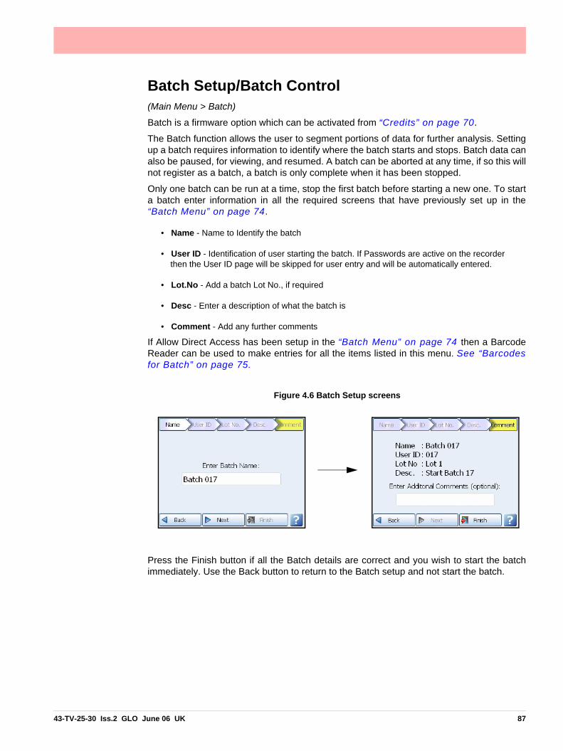
Batch Setup/Batch Control(Main Menu > Batch)
Batch is a firmware option which can be activated from “Credits” on page 70.
The Batch function allows the user to segment portions of data for further analysis. Settingup a batch requires information to identify where the batch starts and stops. Batch data canalso be paused, for viewing, and resumed. A batch can be aborted at any time, if so this willnot register as a batch, a batch is only complete when it has been stopped.
Only one batch can be run at a time, stop the first batch before starting a new one. To starta batch enter information in all the required screens that have previously set up in the“Batch Menu” on page 74.
• Name - Name to Identify the batch
• User ID - Identification of user starting the batch. If Passwords are active on the recorder then the User ID page will be skipped for user entry and will be automatically entered.
• Lot.No - Add a batch Lot No., if required
• Desc - Enter a description of what the batch is
• Comment - Add any further comments
If Allow Direct Access has been setup in the “Batch Menu” on page 74 then a BarcodeReader can be used to make entries for all the items listed in this menu. See “Barcodesfor Batch” on page 75.
Press the Finish button if all the Batch details are correct and you wish to start the batchimmediately. Use the Back button to return to the Batch setup and not start the batch.
Figure 4.6 Batch Setup screens
43-TV-25-30 Iss.2 GLO June 06 UK 87

Batch Mark on ChartA Batch Mark on Chart will be placed on all process screens that have a chart displayed.The mark on chart will show where the batch is started with //S (Batch Name).
The next time you press the Batch button the screen will have changed to give you the BatchControls. The batch control buttons enable the user to Stop, Pause (Resume), Abort or adda Comment to the current batch that has been started.
A Batch is complete when it has been stopped. When a batch is stopped //E appears as amark on chart on the screen. If the batch is aborted it is not a complete batch and will bemarked on the chart with an //A to show it has been aborted.
If the recorder is not logging, starting a batch will automatically start the logging. Howeverstopping the batch will not stop the logging.
If a batch is Paused //P will appear as a mark on chart and the Pause button on the BatchControl menu is replaced with a Resume button. When Resume is selected the screen willbe marked with //R.
Start Batch Mark on Chart
This icon changes to showa batch is in progress
88 43-TV-25-30 Iss.2 GLO June 06 UK

When the batch is stopped the Batch Control screen reverts back to the Batch Setup screenso the user can start a new batch. “Batch Setup screens” on page 87.
As well as a Mark on Chart for every command applied to the batch you can check the Mes-sages screen for details of the batch activity.
Batch Commands
• //S = Start Batch
• //E = End or Stop Batch, this will complete the batch run
• //P = Pause the batch in progress
• //R = Resume batch. Only available when a batch has been paused
• //A = Abort batch. If the batch is aborted it is incomplete and the batch will be cancelled
• //I = User ID. Displays the user entered ID or User ID entered automatically by the Pass-word function.
• //D = Description. User entered description of the batch in progress
• //L = Lot No. User entered Lot number for the batch in progress
• //C = Comment. Extra comment field of additional information for the batch in progress
Figure 4.7 Batch Control screen and Messages screen
43-TV-25-30 Iss.2 GLO June 06 UK 89

Recording Menu(Main Menu > Recording)
This will display the current recording status of the recorder and allow recording control.
Recording MethodologyThe X Series recorder uses a new and powerful method for recording. Data is acquired, atpen specific rates, processed and stored in the large on-board Flash memory. This memoryoperates in a cycle mode such that the oldest data is overwritten by the newest.
When data is exported from the X Series recorder this does not delete that data from therecorder but retains it for further or future downloads. With this method the user can exportmultiple copies of the same encoded data, giving extreme security.
Storage Media FormatNew Compact Flash cards and USB storage keys are pre-formatted for use in the recorderand PC. If you have a used compact flash or USB key we recommend you erase it. Format-ting of Compact Flash cards and USB keys can be done through your PC. The formattingtypes accepted by the recorder are FAT, FAT16 (2GB limit), TFAT and FAT32.
Recording: The top line displays the current pen recording status and the current numberof pens recording
The Recording screen will allow the user to manually Start and Stop recording. Select eitherthe start or stop buttons to activate the function for All pens, a Group of pens (if a group isdefined) or By Pen to identify an individual pen(s).
Export: “Export: required in XXh:XX minutes” is the Memory Usage Information
This is the amount of days, hours and minutes left until the internal memory buffer starts tobe overwritten. Exporting does not remove the data from the recorder but when the internalmemory buffer is full the latest data will start to over-write the oldest data.
Data can be exported to a Compact Flash card or a USB key. There are two USB ports, oneunder the front flap and one at the rear of the recorder. The Compact Flash slot is under thefront flap. The export screen shows two USB buttons, USB1 is the first device to be pluggedin and USB2 is the second device to be plugged in. If a power failure occurs USB order rec-ognition is lost.
90 43-TV-25-30 Iss.2 GLO June 06 UK

Export Now(Main Menu > Recording > Export Now)
Export Now will transfer data to the external media such as Compact Flash or USB key.
Select the Export Now button to go to a sub-menu of available external storage devices.
Buttons become active when a device is fitted. Once fitted the size of the device memoryand the amount of available space is displayed.
Select the desired device to export to and this will display two options New and All. The Allfunction will export all the data in the recorder’s memory to the external device port. The Newfunction will just export any new data since the last export was made to this port.
If an Export Now is requested within 5 seconds of a Scheduled export being activated, themanual export will not occur.
Scheduled Export(Main Menu > Recording > Scheduled)
Set up Scheduled exports to transfer data at timed intervals, from internal memory to exter-nally attached devices, Compact Flash or USB storage key.
Select the Scheduled button to go to a sub-menu of available external storage devices.
Buttons become active when a device is fitted. Once fitted the size of the device memoryand the amount of available space is displayed.
Select the external device to copy the data to and choose a time period from the list. Thiswill copy data at the time period stated until the device is full or is deactivated.
If a manual Export Now is in progress during the time when a Scheduled export is to occur,the scheduled export will hold off until the manual export is finished.
Device SelectionIf the Device Selection buttons are greyed-out you will need to insert a Compact Flash orUSB key into the port. After a few seconds the button becomes active.
USB1 is the first USB fitted and USB2 is the second one fitted, front or rear of the recorder.
Export “busy” lightWhen data is about to be exported to a device the transfer busy light starts flashing. Theflashing LED is a warning that the recorder is about to export to media. DO NOT remove themedia whilst the LED is flashing. After a few seconds the flashing LED goes to “Full On”LED. Whilst the LED is fully on data is being written to the media. DO NOT remove the mediawhilst the LED is on. When the transfer is complete, the LED goes off and the media maynow be removed.
43-TV-25-30 Iss.2 GLO June 06 UK 91

Messages Menu(Main Menu > Messages)
The messages screen will display a selection of message areas. Specific types of messageshave been put into categories or all messages can be viewed. The number of new messag-es to view are displayed on each button as a number in brackets after the label.
Message Types
• All - Select this to view a list of All types of messages. The messagesscreen will hold the latest 200 messages.
• Alarms - This is a list of active alarms that have occurred. The screen willdisplay the Type of alarm, the Time and Date that the activity occurred andMessage details of the activity.
• System - This will list a history of system messages. The screen will dis-play the Type of messages and warnings and errors that have been gener-ated by the unit. The screen will also display the Time and Date that theactivity occurred and the Message details.
• Diagnostics - Examine a complete list of the recorder’s functionality andprocesses since it was last powered up. The screen will display Type ofmessage, Time and Date that the activity occurred and the Messagedetails.
• Security - Audit trail of entries made to secure areas such as Passwordsetup, including, Log on, Log off, what area has been accessed, time/dateand the user name.
• Users - These are messages that have been entered by the user by enter-ing a Mark on Chart. The screen will display the Type of message, Timeand Date that the activity occurred and the Message details.
92 43-TV-25-30 Iss.2 GLO June 06 UK

Message ListAll messages will conform to the following format
The messages screen will hold the latest 200 messages.
Message button barThe message button bar runs along the bottom of all messages screens. The button are:
• Back - Takes you back to the main Messages screen.
• Jump - Select an item in the message list and press the Jump button. Thiswill take you to the exact time of the occurrence on the replay screen.See “Replay” on page 123. If the message requested is older that theoldest chart time/data available a message box will appear and jump you tothe oldest chart time and date available.
43-TV-25-30 Iss.2 GLO June 06 UK 93

Message Format
Table 4.5 : Message Types
Icon Type Description
Alarm Red Bell = in Alarm and not acknowledged
Alarm Green Bell = out of alarm
Alarm Green Bell / Black outline = out of alarm and acknowledged
Alarm Green/Yellow bell = out Alarm not acknowledged
Alarm Red/Green bell = in Alarm and acknowledged
System/Diagnostics Information, General (eg. System check)
System/Diagnostics Warning!(eg. media error, FTP failure, Timouts)
System/Diagnostics Error(eg. Password failure, power failure, no media)
Security Security audit trail
Security Log In - open paddlock
Security Log Out - closed paddlock
Security Access Failure - No entry sign
User Mark on Chart and Batch
User Start - Logging or Totals
User Stop - Logging or Totals
User Pause - Logging or Totals
User Reset - Logging or Totals
94 43-TV-25-30 Iss.2 GLO June 06 UK

Process Menu(Main Menu > Process)
If Max/Min or Totals are set up in the recorder they can be controlled from this screen.
Controls for any process in use:
• Max/Min - Reset Max/Min, Maximum or Minimum values by categories;
• Totals - Start, Stop, Reset or View Totals by categories
Note on GroupsGroups of pens need to be set up to use this feature, see “Pens Menu” on page 51
Max/Min(Main Menu > Process > Max/Min)
Reset all Maximum and Minimum values by categories or just reset max or min values. Thecategories are:
All - Select this to reset all values.
By Groups - If Groups of pens have been set up this can be used to reset the max/min val-ues for particular groups of pens. To set up Groups see “Pens Menu” on page 51
By Pen - Select this to reset max/min values for individual pens.
View - Use the View button to just display the max/min values for each Pen.
Totals(Main Menu > Process > Totals)
Select a button to Start, Stop or Reset Totals. These can be controlled by the following cat-egories:
All - Select this to start, stop or reset all Totals.
By Group - If Groups of pens have been set up this can be used to start, stop or reset par-ticular groups of pens. To set up Groups see “Pens Menu” on page 51
By Pen - Select this to start, stop or reset individual pens.
View - Use the View button to just display the Totals values for each Pen that is totalising.
When the configuration is complete select the Finish button to Commit, Discard or CommitLater. Select the Back button to return to the previous menu.
43-TV-25-30 Iss.2 GLO June 06 UK 95

Status Menu(Main Menu > Status)
Use the Status menus to easily check on the current configuration of the recorder. A numberof status information screens are available to the user, these will provide information for re-porting and diagnostic purposes.
The following Status screens are available
• System - information about the recorder setup such as Device information,software and firmware versions, the recorder IP address, firmware Optionsand Hardware in the recorder
• Pen Overview - Pen configuration details
• Maintenance - Recorder Health watch for preventative maintenance (Thisis a Firmware activated option that requires credits)
• Recording - Status of all Pens currently recording
• Diagnostics - Complete diagnostics for Field IO, Comms and Media.Comms is a Firmware activated option that requires credits
Printing ScreensAll the Status screens have a Print button, to execute this, the printer must first be configuredin the “Printer Menu” on page 75. For details on suitable printer types see “Print Sup-port” on page 24.
System(Main Menu > Status > System)
The System status menu is divided into three more sub sections: General, Options and IOCards. Each one will display the current status of the recorder for each category.
96 43-TV-25-30 Iss.2 GLO June 06 UK
General(Main Menu > Status > System > General)
Displays the version status for the different types of firmware, hardware and current recorderinformation.
Go Back to return to the previous screen or select Print to print the screen.
Options(Main Menu > Status > System > Options)
Displays a list of firmware options available and which ones are enabled.
For more information see See “Section 7: Firmware Options” on page 129
Table 4.6 : System Version Status
Options Version
ID 0001
Name QX
Serial No. * * * * * *
Processor ***MHz
Firmware **
Firmware Data 16:33:33 May 11 2006
Bridge Firmware **
Platform 5.**
Boot Loader 1.**
Mac address 00-d0-6e-**-**-**
IP Address 160.221.***.***
Front USB Host Mode
Table 4.7 :
Options Credits Enabled
Full Math 4 or
Scripting (+ Full Maths) 6 or
Events 6 or
Fast Scan 5 or
Totals 4 or
43-TV-25-30 Iss.2 GLO June 06 UK 97

*Password CFR - (ESS - Extended Security System). This will only appear in the list if thisfeature is enabled in the recorder. It cannot be enabled by the firmware credit system - con-tact Honeywell for details.
Go Back to return to the previous screen or select Print to print the screen.
IO Cards(Main Menu > Status > System > IO Cards)
This will display the Slot position of each card in the recorder. The Card Type is identifiedas Analogue I/P, Alarm/Digital I/O, Analogue O/P or Pulse Input. The number of Channelson each card eg. Digital I/O 1-16. The Firmware Version of the card is displayed and theBoard Revision.
Go Back to return to the previous screen or select Print to print the screen.
Custom Screens 4 or
Maintenance 2 or
Print Support 2 or
Batch 3 or
Groups 2 or
Remote Viewer 3 or
OPC Server 8 or
Extra Pens 2 per 4 pens Total Pens
*Password CFR NA or
Total Credits no. used/no. available
Table 4.8 : Example of IO Card Status
Slot Card Type Channels FW Version Board Revision
A Analogue I/P 1-8 A*-00* 0
B Pulse 9-12 A*-00* 1
G Digital I/O 1-16 A*-00* 0
Table 4.7 :
Options Credits Enabled
98 43-TV-25-30 Iss.2 GLO June 06 UK

Pen Overview(Main Menu > Status > Pen Overview)
Each pen is displayed with full configuration details.
• Pen - Displays the pen number and ticked if it is enabled
• Value - Displays the current reading for this pen
• Maths - Displays any Maths calculation applied to this pen or the Analogue Input channel for this pen. Summarised to M for any Maths expressions.
• Scale - Displays the High and Low limits of the scale range for this pen
• In Alarm - Displays the current status of the alarm, tick = active and a cross = inactive.
• Pen Rate - This displays the fastest of all dependencies
• Alarm - Displays how many alarms are enabled on this pen
• Total - This will be ticked if a totaliser has been enabled on this pen
• Group - Displays the group number if this pen has been allocated to a group.
Go Back to return to the previous screen or select Print to print the screen.
Maintenance(Main Menu > Status > Maintenance)
The recorder keeps track of important “life actions” for improved diagnostics and preventa-tive maintenance notification.
Health Watch/Maintenance is available as a firmware option. To enable this go to Optionsin “Options” on page 97.
Once enabled this screen will keep the following information:
• Powered on - How many times the recorder has had the power turned on
43-TV-25-30 Iss.2 GLO June 06 UK 99

• Last Power up - The last time the recorder had been turned on
• Inetrnal Mem Id - This number is made up from the size of the memory card and what type of format it is. Eg 128T16 = 128MB size formatted to TFAT16
• Time On since power up - The amount of time since the recorder was last turned on
• Total On time - How much time the recorder has had the power turned on
• Total Off time - How much time the recorder has had the power turned off
• Longest Off time - How long was the longest time period the recorder was powered off
• Lithium cell life - Approximately how much battery time is left
• Backlight Life - Approximately how many hours of Back light time left
• Compact flash - How many times the Compact flash card has been inserted
• Lowest temperature - Displays the lowest ambient recorder temperature detected so far
• Highest temperature - Displays the highest ambient recorder temperature detected so far
• AI last factory cal * - When the last factory calibration was made to this Analogue Input card. Eg. in card slot A
• AI last user cal *:* - When the last user calibration was made to this Analogue Input card. Eg in slot position A, input 1. All channels will be listed per channel.
• Relay * cycle(s) - Displays the amount of relay cycles per relay listed.
• Fixed - reports common relay output cycles
• Last Setup Modified - displays the last Day, Month and Time the setup was last modified.
Go Back to return to the previous screen or select Print to print the screen.
100 43-TV-25-30 Iss.2 GLO June 06 UK

Recording(Main Menu > Status > Recording)
Shows the current logging status of all pens within the system:
• Pen - Displays the Pen number and will display a tick when recording and a cross when recording has stopped.
• Value - Displays the current pen value
• Method - Displays Sample, Max/Min or Average logging
• Log Rate - Displays the Log rate set, in Hertz. A tick denotes if it is enabled and a star will indicate the current log rate
• Alarm Rate - Displays the alarm rate, in Hertz, if this has been set up to change when the pen goes into an active alarm state. A tick denotes if it is enabled and a star will indicate the current log rate
• Group - Displays the name of the group that this pen has been assigned to.
Go Back to return to the previous screen or select Print to print the screen.
Diagnostics(Main Menu > Status > Diagnostics)
Complete diagnostics is shown for each of the following categories:
Analogue In(Main Menu > Status > Diagnostics > Analogue In)
43-TV-25-30 Iss.2 GLO June 06 UK 101

• Channel - Displays the Slot position eg. A, B, or C, D, E, F, the Analogue Input number and the system channel position. This will show a tick if this channel is enabled.
• Input - Displays the current Analogue Input reading for this channel.
• Range - Displays the current Range Type set for this channel, eg. +/-12V
• Calibration - Displays the type of calibration for this channel either Factory or User Cal
• Sample Rate - Displays the current Sample rate for this channel.
• SQRT - If ticked the square root extract is enabled on this channel to linearise a non-linear input.
• Sensor Comp - This will display if any type of sensor compensation applied to this chan-nel.
• Pen - Displays which Pen scale is being used to display this analogue input.
• CJC - Only for Thermocouple inputs. Displays the final adjusted value of a Cold Junction Calibration on this channel in degrees C.
Go Back to return to the previous screen or select Print to print the screen.
102 43-TV-25-30 Iss.2 GLO June 06 UK

Analogue Out(Main Menu > Status > Diagnostics > Analogue Out))
• Channel - Displays the Slot position, eg. B, E or F, the Analogue Output number and the system channel position. This will show a tick if this channel is enabled.
• TX Pen - Displays which pen is transmitting the signal
• Range - Displays the Output range set. A tick here will indicate this is overrange.
• Output - Displays the current Analogue Output reading for this channel.
Go Back to return to the previous screen or select Print to print the screen.
Alarm/Digital IO(Main Menu > Status > Diagnostics > Digital IO)
• Channel - Displays the Slot position, eg. G, H or I, the Digital IO number and the system channel position. This will show a tick if this channel is enabled. Fixed refers to the common relay output on the power board (24V relay)
• Input/Output/Pulse - Displays what activity is on this channel, Input, Output or Pulse Input.
• Alarm - Displays the Pen number and the Alarm number that activates the digital output when the alarm is active. The Alarm has to be set to Relay out.
• Status - Displays the current state of the digital input on this channel or pulsed if Pulse Out is selected. The relay is displayed as open or closed.
• Duration - Displays the Output Pulse duration set.
Go Back to return to the previous screen or select Print to print the screen.
Pulse Inputs(Main Menu > Status > Diagnostics > Pulse Inputs)
• Channel - Displays the Slot position, eg. A, B, C, D, E or F, the Pulse Input number and the system channel position. This will show a tick if this channel is enabled.-
• Frequency/Count - Displays the input mode, fixed as Frequency (in Hertz)
• Input - Displays the current Pulse Input reading for this channel (in Hertz)
Go Back to return to the previous screen or select Print to print the screen.
Comms(Main Menu > Status > Diagnostics > Comms)
This screen contains a description of the type of comms currently being used and its status.
• Description - Displays current Comms information. eg. Ethernet or IP address
• Status - Displays the status of the Ethernet eg. Active 100Mb Full Duplex and the status of the IP address eg. Dynamic:160.220.***.***
Go Back to return to the previous screen or select Print to print the screen.
43-TV-25-30 Iss.2 GLO June 06 UK 103

Finish
Media(Main Menu > Status > Diagnostics > Media)
• Drive - If media is inserted this will display a lists the drives available.
• Size - If media is inserted this will display the size of the media will be displayed
• Free - If media is inserted this will display how much free space is available. Eg. USB2 size is 256MB of which 190MB is free.
• Status - Displays the current status of the media eg. Being re-cycled, Schedule:Inactive
• Setup files - Displays the type of files that can be loaded into the recorder eg: .set, .lay, .tpl
Go Back to return to the previous screen or select Print to print the screen.
FinishWhen the Finish button is pressed at the end of a new set up or a change to a setup thefollowing options are available.
CommitThis will save the new setup or changes to an existing setup, over-writing the existing one,and implement them into the recorder
Field validation is performed when a change has been made, if a problem is identified, anerror message is shown and the field in question clearly marked.
DiscardThis will ignore the new setup, or the changes that have been made to the existing setup,and not implement them into the recorder
Commit LaterThis gives the user the option for a configuration to be partially completed but to be commit-ted at a later date. This will retain the new set up or the changes to the existing setup untilthey are required. A partially completed setup will not be maintained over a power failure.
If Commit Later has been executed, a warning message will display for Edit Setup, Edit Lay-out and User Admin (Passwords) screens. This is to alert the user that the changes havebeen made to the configuration and not committed in the recorder. The user can Discard thechanges or continue to do changes and then Commit them.
104 43-TV-25-30 Iss.2 GLO June 06 UK

Section 5: Password Security
Log On/OffIf ESS (Extended Security System) Password security is active on your recorder a passwordis required to enter the menu system and process screens. Limited access is available with-out logging on, see Table 5.1 on page 109.
When Log On is required the Log On button will appear in the top right of the Main Menuscreen. The Log On button can be set to switch to auto Log Off at a specified period of time.To Log On select the Log On button at the top right of the Main Menu screen.
Log On - User is presented with a user name and password box.First time user login is “Admin”. No password is required. Access forthe first time user is removed once the password system has beenconfigured.
Log Off - Once the user has logged on, the option in the Main Menuwill turn to Log Off, once selected the user is logged off and returnedto the current process screen.
User Log in/Log Out MethodUsers can log in and out of the system or web page easily using the touch screen or an at-tached keyboard.
Users and GroupsNumber of UsersThe system will support up to 50 users.
Multiple Log On’sUsers are allowed to log on to the system more then once, allowing the same user to log on from different areas, e.g. via the user interface and via web browser at the same time.
User NameEach user must have a user name, this is a maximum of 20 characters in length and cannot be duplicated. Numeric characters and symbols can be used in the user name, but no spac-es.
User GroupEach user can be allocated to a group, these are defined as follows
AdministratorAdministrator has access to everything, and it is possible to have more than one user at the administrator level. The Administrator will have unlimited access to the system and provide the ability to setup other users.
With the exception of Administrator who has access to everything, the other 4 groups per-missions can be configured, users can then be allocated to a level and they will inherit those permissions.
43-TV-25-30 Iss.2 GLO June 06 UK 105

PermissionsPermissions may also be customised for an individual user, their permissions can be changed to become a customised user. However for global access restrictions, the user must be allocated a security level of Engineer, Supervisor, Technician or Operator, even though the individual permissions will differ.
First Time’ Password System SetupThe first time the system is used a default user name and password is available, the user name is “Admin” and will have no password, this is known as the “first time” user. Access to the first time user is removed once the password system has been configured. The first time user is reinstated if the password system is reset.
ESS - Extended Security System (CFR21 Part 11)The password system allows for user names to be typed in. All logging in and out activity is automatically stored in the audit trail.
If your recorder is fitted with the ESS pasword system follow these instructions
First Time Password System Setup – Add System Administrator
Follow these steps on first time power up.
Administrator User name1. Switch the recorder On
2. From the process screen press the Menu button in the top left of the screen and select the Log In icon in the top right as shown here.
3. A box will appear and prompt you to enter a User name, enter Admin. This is the first time user login. Access to the first time login is removed once the password system has been configured. The first time user is reinstated if the password system is reset. No password is required for first time login. No password is required for first time login.
4. From the Main menu press the following buttons:
Configure > Passwords > User Admin > Add UserSelect “Blank User” and type in your new administrator user name
• Default User name minimum length is 4 characters. (Allows the use of alpha, symbol and numeric characters, no spaces)
• Default User name maximum length is 20 characters
5. In the Add User menu your new user name will be displayed, select this (default Opera-tor) and change the User Level to “Administrator”. Select Finish and Commit.
6. A box will appear when you have successfully added a user, press OK
7. The recorder will return to the process screen.
You have now added an Administrator User Level to the password system. You must now give the new user a password
Administrator Password 1. From the process screen press the Menu button in the top left of the
screen and select the Log In icon in the top right as shown here.
Your recorder is configured with ESS – Extended Security System. This is a password system that cannot be switched off
106 43-TV-25-30 Iss.2 GLO June 06 UK

2. A box will appear and you will be prompted for your Administrator user name, which you have just created in items 1 to 7 listed above.
3. The Password dialog box will appear. The recorder enters a default password when a user is added so select “Yes” to change it.
• Default Password minimum length is 6 characters (requires a minimum of 5 alpha char-acters. Allows the use of symbols and numeric characters, no spaces)
• Default Password maximum length is 20 characters
4. Enter your new password, then repeat to confirm.
5. The password dialog will appear confirming the change has been successful.
6. You have now completed creating an Administrator.
You can now enter the password system to check and reset the default Policies, eg. Pass-word Expiry Time. (Main Menu > Configure > Passwords > User Admin > Policy)
Refer to the Password section in the User manual for more information.
User Name DescriptionUser names are case dependent however duplicate user names will not be allowed even if case does not match. The user name and password cannot be the same.
Minimum Access LevelA feature to allow the minimum level access is available. For example: when a batch starts the recorder will block access to all users of access level Technician and under, so techni-cians and operators would not be able to log on after a batch start. When a batch ends then the minimum access level can be reverted to including operator.
Calendar FunctionDay of week restriction is required for all levels apart from Administrator, this will consist of any combinations of 7 days. An everyday selection is available.
Password PolicySee “Policy” on page 81.
Duplicate PasswordsDuplicate passwords are allowed for different users, otherwise this would alert a user that the same password is available on another user login. The User name and password cannot be the same.
Retry LockoutA password retry lockout option is available, if the user enters the incorrect password for a preset number of times in a row, the account must be de-activated and only an Administrator can re-activate the account. The account can be reactivated in 2 ways
Retry & Preserve PasswordReset retries (unlock) and preserve password, allowing user to have another try
Retry & Reset PasswordReset retries (unlock) and reset password which must be changed on first login.
43-TV-25-30 Iss.2 GLO June 06 UK 107

User Interface requirementsNo Activity TimeoutA “no activity” timeout programmable from 20 to 3600 seconds, which will automatically log out a user after a defined period of inactivity at the menu system or web page.
Level NamesThe level names, such as Operator, Technician, Supervisor, Engineer are for internal refer-ence and are displayed as defaults, it is possible for the user to change the group names to suit their personnel structure. This is stored in the policy set up for the Password configura-tion.
Audit TrailA full audit trail is available and is stored as a message log.
Trail RulesThe audit trail cannot be turned off and will always be generated for the password system.
Audit Trail EntriesAudit trail is generated for the following actions
• User log On/Off and source (Recorder, Web)
• Failed password attempts
• Areas where access was attempted but denied
• Password expiry
• Inactivity timeouts/auto logouts
• Temporary User entry
108 43-TV-25-30 Iss.2 GLO June 06 UK

Level PermissionsTable 5.1 : Default Level Permissions
Default user levels of access to areas within the recorder menu system
Permission Area Admin Engineer Supervisor Technician Operator No Login required
Perm Area 1 Messages
Perm Area 2 Screen
Perm Area 3 Status
Perm Area 4 View Totals
Perm Area 5 View Alarms
Perm Area 6 View Max/Min
Perm Area 8 Acknowl-edge Alarms
Perm Area 9 Configure Alarms
Perm Area 10 Batch Control
Perm Area 11 Recording
Perm Area 12 Change Password
Perm Area 13 Main Con-figue Menu
Perm Area 15 Configure Totals
Perm Area 16 Configure Max/Min
Perm Area 17 Load/Save Setups
Perm Area 18 Main Setup Menu
Perm Area 19 Edit Setup
Perm Area 20 General Setup Menu
Perm Area 21 Printer Setup
Perm Area 22 Batch Setup
43-TV-25-30 Iss.2 GLO June 06 UK 109
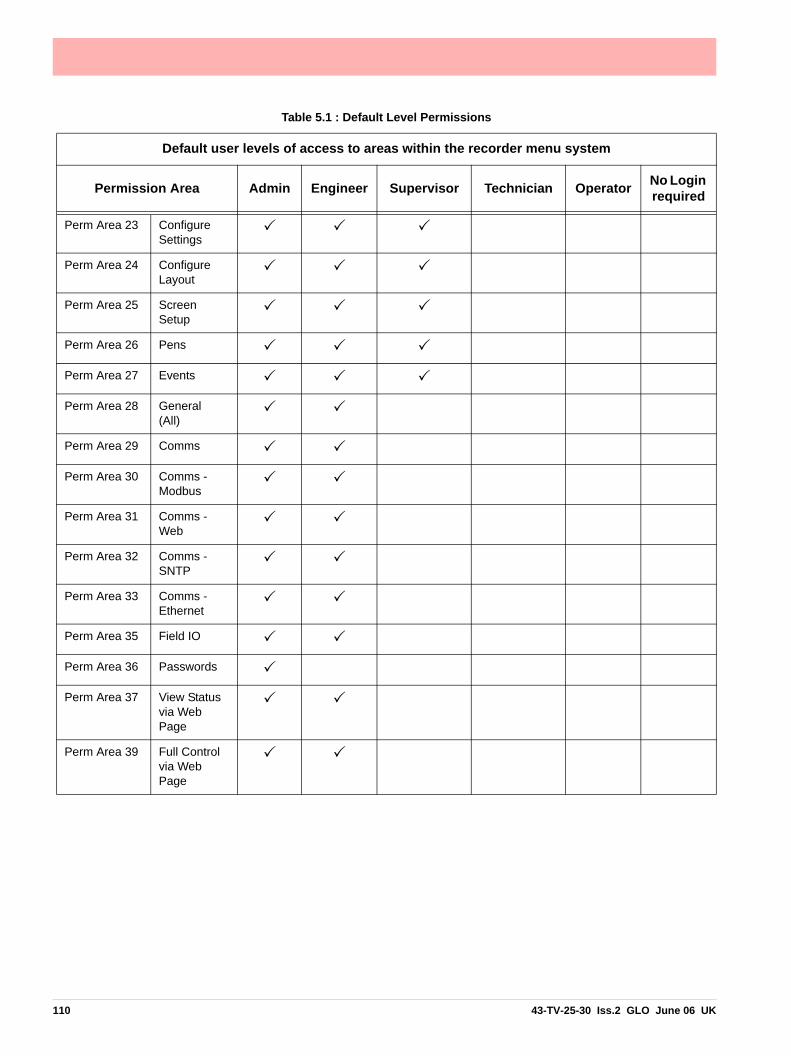
Perm Area 23 Configure Settings
Perm Area 24 Configure Layout
Perm Area 25 Screen Setup
Perm Area 26 Pens
Perm Area 27 Events
Perm Area 28 General (All)
Perm Area 29 Comms
Perm Area 30 Comms - Modbus
Perm Area 31 Comms - Web
Perm Area 32 Comms - SNTP
Perm Area 33 Comms - Ethernet
Perm Area 35 Field IO
Perm Area 36 Passwords
Perm Area 37 View Status via Web Page
Perm Area 39 Full Control via Web Page
Table 5.1 : Default Level Permissions
Default user levels of access to areas within the recorder menu system
Permission Area Admin Engineer Supervisor Technician Operator No Login required
110 43-TV-25-30 Iss.2 GLO June 06 UK

Default Password AccessDefault password access is set up within the recorder and can be changed by the Adminis-trator or the Administrator can assign another user to change the access permissions.
Default permissions• Administrator Access is for the Administrator level only
• Engineer Access is for Engineers and above (Administrator level)
• Supervisor Access is for Supervisors and above (incl. Engineer and Administrator levels)
• Technician Access is for Technicians and above (incl. Supervisor, Engineer and Adminis-trator levels)
• Operator Access is for Operators and above (incl. Technicians, Supervisors, Engineers and Administrator levels)
• No Login gives access to all.
Access levels can change for each menu, for example Operator or above access is requiredto get to the Configure menu. Once in the Configure menu the operator level can only ac-cess the Passwords button, Setup is Technician or above access and Layout and Settingsare Supervisor or above access.
43-TV-25-30 Iss.2 GLO June 06 UK 111
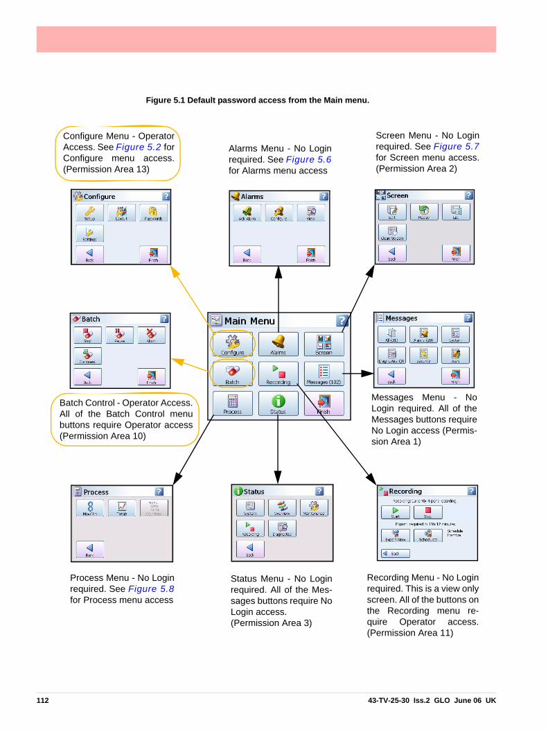
Figure 5.1 Default password access from the Main menu.
Configure Menu - OperatorAccess. See Figure 5.2 forConfigure menu access.(Permission Area 13)
Batch Control - Operator Access.All of the Batch Control menubuttons require Operator access(Permission Area 10)
Alarms Menu - No Loginrequired. See Figure 5.6for Alarms menu access
Screen Menu - No Loginrequired. See Figure 5.7for Screen menu access.(Permission Area 2)
Messages Menu - NoLogin required. All of theMessages buttons requireNo Login access (Permis-sion Area 1)
Status Menu - No Loginrequired. All of the Mes-sages buttons require NoLogin access. (Permission Area 3)
Process Menu - No Loginrequired. See Figure 5.8for Process menu access
Recording Menu - No Loginrequired. This is a view onlyscreen. All of the buttons onthe Recording menu re-quire Operator access.(Permission Area 11)
112 43-TV-25-30 Iss.2 GLO June 06 UK

Figure 5.2 Default password access from the Configure menu
Configure menu - Operator access(Permission Area 13)Setup = Technician access Layout = Supervisor accessPasswords = Operator accessSettings = Supervisor access
Settings menu - Supervisor access(Permission Area 23)
Setup menu - Technician access.See Figure 5.3 for Setup menuaccess. (Permission Area 18)
Layout menu - Supervisor access.All of the Layout menu buttons require Supervisor access. (Permission Area 24)
Password menu - Operator access.See Figure 5.4 for Password menuaccess. (Permission Area 36)
43-TV-25-30 Iss.2 GLO June 06 UK 113
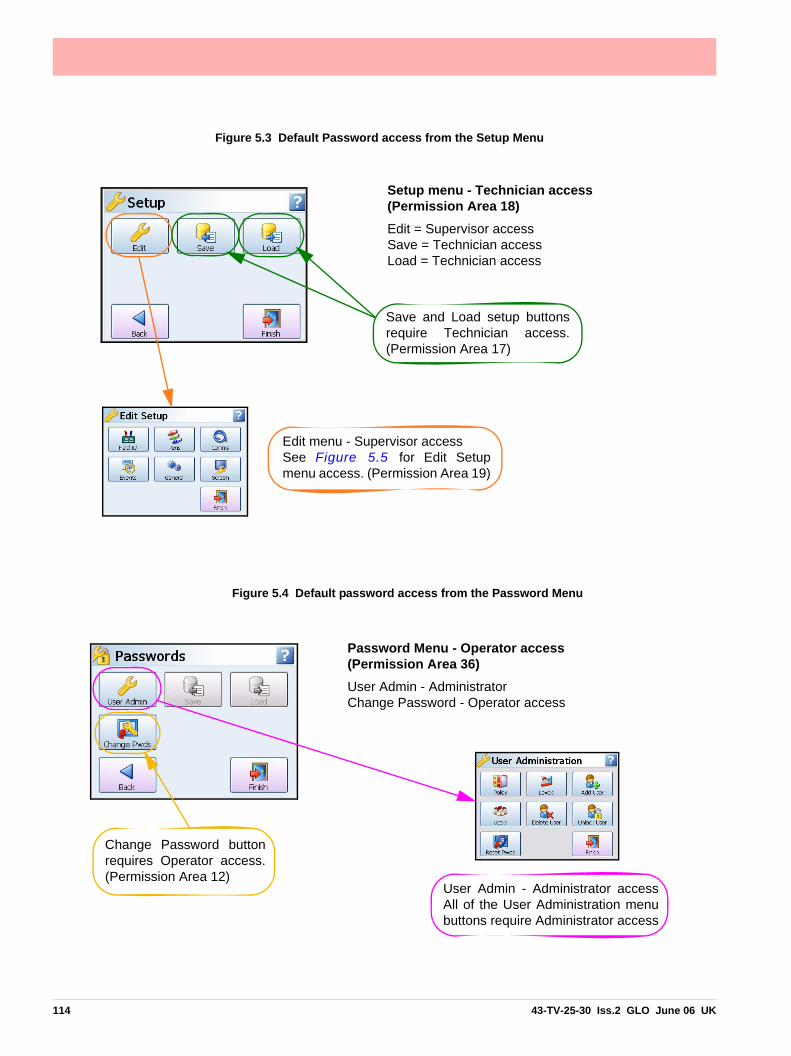
Figure 5.3 Default Password access from the Setup Menu
Edit menu - Supervisor accessSee Figure 5.5 for Edit Setupmenu access. (Permission Area 19)
Save and Load setup buttonsrequire Technician access.(Permission Area 17)
Setup menu - Technician access(Permission Area 18)Edit = Supervisor access Save = Technician access Load = Technician access
Figure 5.4 Default password access from the Password Menu
Change Password buttonrequires Operator access.(Permission Area 12)
Password Menu - Operator access(Permission Area 36)User Admin - AdministratorChange Password - Operator access
User Admin - Administrator accessAll of the User Administration menubuttons require Administrator access
114 43-TV-25-30 Iss.2 GLO June 06 UK

Figure 5.5 Default password access from the Edit Menu
Field I/O Menu - EngineeringAccess. All of the Field I/Obutton require Engineeringaccess. (Permission Area 35)
Pens Menu - Supervisor Access.(Permission Area 26)
Comms Menu - Engineering Access. See Figure 5.10 forComms access. All of theComms menu buttons requireEngineering access. (Permission Area 29)
Screen Setup Menu - Super-visor Access. All of theScreen menu buttons requireSupervisor access. (Permission Area 25)
General menu - SupervisorAccess. See Figure 5.9for General menu access.(Permission Area 20)
Events menu - SupervisorAccess. All of the Eventsmenu buttons require Super-visor access. (Permission Area 27)
Edit Setup Menu - Supervisoraccess (Permission Area 19)Field I/O - Engineering accessPens - Supervisor access Comms - Engineering access Events - Supervisor accessGeneral - Supervisor accessScreen - Supervisor access
43-TV-25-30 Iss.2 GLO June 06 UK 115

Figure 5.6 Default password access from the Alarms Menu
Alarms menu - No Login Ack Alarm - OperatorConfigure - OperatorView Alarms - No Login
Ack Alarm menu - Operator access. (Permission Area 8)
All of the AcknowledgeAlarm buttons require Operator access
Configure Alarms requires Operator accessPermission Area 9)
View Alarms requires No Login(Permission Area 5)
Figure 5.7 Default password access from the Screen Menu
Screen Edit - Supervisor access All of the Edit functions in the statusbar require Supervisor access
Screen menu - No Login required(Permission Area 2)Edit - Supervisor accessReplay - No Login requiredList - No Login requiredClean Screen - No Login required
Replay, List and Clean Screenbuttons require No Login access
116 43-TV-25-30 Iss.2 GLO June 06 UK

Figure 5.8 Default password access from the Process Menu
Process Menu - No Login requiredMax/Min - No LoginTotals - No Login
Totals Menu - No Login required
Start, Stop and Reset Totals buttons require Technician access(Permission Area 15)
View requires No Login (Permission Area 4)
Max/Min Menu - No Login required
Reset Max/Min, Reset Max and ResetMin buttons require Technician access(Permission Area 16)
View requires No Login(Permission Area 6)
Figure 5.9 Default password access from the General Menu
Factory menu requires Engineeringaccess. All of the factory menu buttonsrequire Engineering access. (Permission Area 28)
General Menu - Supervisor access (Permission Area 20)Ident, Localisation and Factory require Engineering access. (Permission Area 28)
Batch requires Supervisor access (Permis-sion Area 22)
Printer requires Supervisor access (Permis-sion Area 21)
Groups require Supervisor access (Permis-sion Area 26)
43-TV-25-30 Iss.2 GLO June 06 UK 117

Figure 5.10 Default password access from the Comms Menu
Comms Menu - Engineering access(Permission Area 29)Modbus - Permission Area 30
Web - Permission Area 31
SNTP - Permission Area 32
Ethernet - Permission Area 33
Figure 5.11 Default password access from the Web page
Web page - Engineering accessView Status - Permission Area 37
Full Control - Permission Area 39
118 43-TV-25-30 Iss.2 GLO June 06 UK

Aa
Section 6: Screen Configuration
Process Screen Overview
Recording menu allows:• stop/start recording• scheduled downloads• immediate download
of recorded data
Modify Replay List of Cycles throughscreen chart available available screenslayouts history screens
cknowledge ll Alarms
Alarm Status/Configure. Individual Alarm Acknowledge
Enter recorder Setup menu
Recorder ID No. & Name (alternates to display the Screen Name)
Time and Date
Chart Area
Realtime Pen Pointers
Pen Digital Read-outAlarm Marker marks the chart to show when Pen 1 was out of its alarm state
Yellow area shows when Pen 1 was in alarm state
Figure 6.1 Minitrend QX Process Screen
Standard Screen example - Chart and DPM
Message Count menu allows quick access to Batch, User Mark on Chart, and Messages Detail
View Alarms
Touch the screen to activate a short cut to Settings such as change the chart speed
43-TV-25-30 Iss.2 GLO June 06 UK 119

Menu BarAt the top of each process screen is the Menu bar.
Menu This gives direct access to the Menu System to set up the recorder. See “Section 4: Re-corder Setup” on page 35.
Alarm bell (1)The second button shows the Alarm status. When the alarm bell is green this means there are no active alarms. If the bell is red then an alarm is active and the number of active alarms will display below.
Press this button to produce the Alarm menu bar. Here there is an Acknowledge button to confirm any alarms that require acknowledgment, these may be normal or latched alarms. See “Alarms Menu” on page 55. There is a View button that displays all pens currently with alarms set up. The Detail button will take you straight to the Alarms menu, see “Alarms Menu” on page 85
Time Left (18h)This button shows how much time is left before data will fill the internal memory and an ex-port of the memory to an external device is required, before data is overwritten. Select this button to go to the Recording screen to export the data now or set up a timed export using the Scheduled option. See “Recording Menu” on page 90.
If the Time Left button shows two green arrows this means that the memory buffer is full and the oldest data has started to be overwritten.
Messages (78)This button produces another button bar for quick access. The number displayed is thenumber of new messages that have been registered since the menu was last checked.
Select this to produce another button bar with access to:
• Batch - Shortcut to enter details to start a new batch or to control a batch that has already been started. See “Batch Setup/Batch Control” on page 87.
• Mark on Chart - There is a Mark button to enter a Mark on Chart.
• Message Detail - Press this button for quick access to the Messages screen, where each message is put into a category or All Messages can be viewed. See “Messages Menu” on page 92.
Recorder ID and Name alternates with the Screen Name.
Date and Time
120 43-TV-25-30 Iss.2 GLO June 06 UK

ScreenThe Screen button produces the Screen menu bar.
Screen Menu Bar• Edit - Quick access to channel mapping. Map channels to pens, switch between Expert
and non-expert mode to select widgets or objects. See Edit below.
• Replay - Gives quick access to the Replay Screen. See “Replay” on page 86.
• List - List of all available screens, select to change the current screen.
• Prev - Displays the previous enabled screen in current selection
• Next - Displays the next enabled screen in current selection
• Exit - Exit this menu, return to the current process screen
Edit, Screen Properties(Main Menu > Screen > Edit)
The Edit button takes you to your current process screen and displays the Edit toolbar at thetop of the screen.
In Edit mode you can select items on the screen and assign channel information to them.
Expert/Non Expert buttonThe screen is made up of widgets and objects, the Expert button switches between beingable to select widgets and objects.
A widget is a container for one or many objects. Objects display data in graphical forms suchas Bar, Scale, DPM, Text.
Figure 6.2 Screen Menu bar
Previous and Next buttons scroll back and forth through the screen list
43-TV-25-30 Iss.2 GLO June 06 UK 121
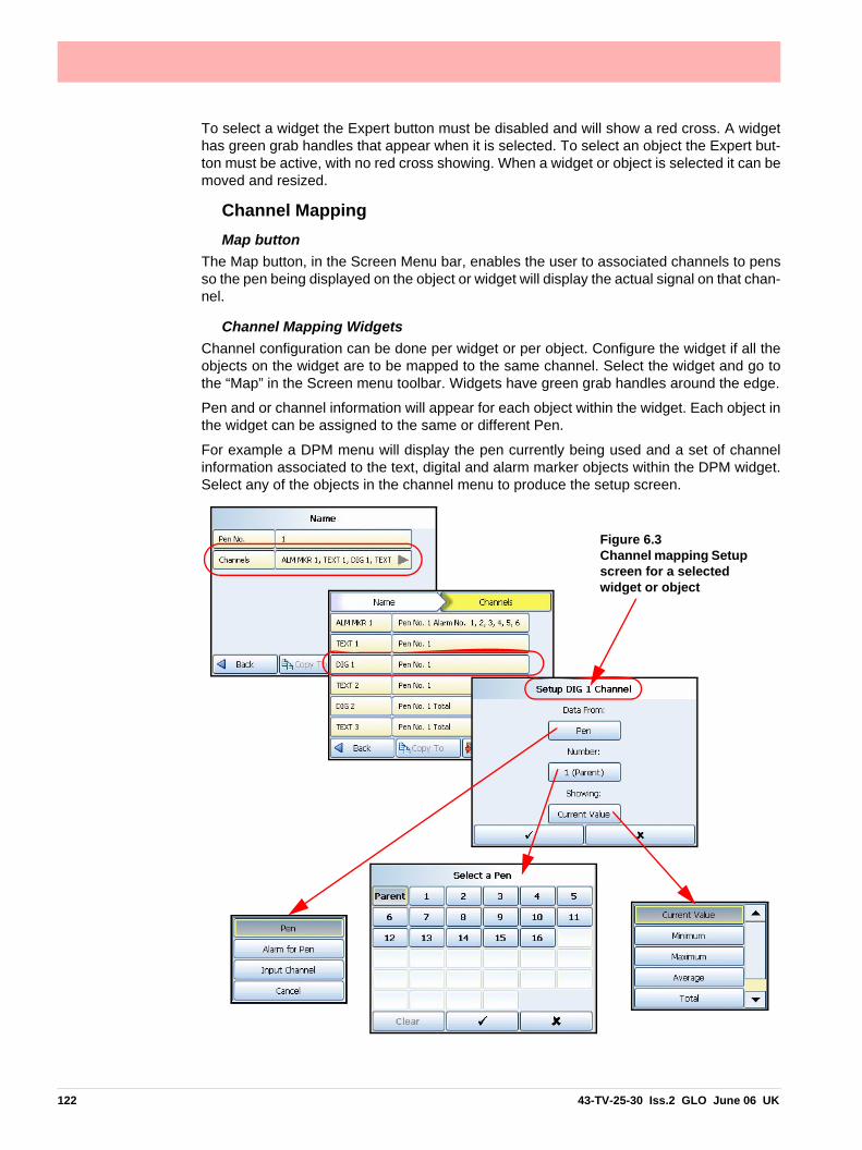
To select a widget the Expert button must be disabled and will show a red cross. A widgethas green grab handles that appear when it is selected. To select an object the Expert but-ton must be active, with no red cross showing. When a widget or object is selected it can bemoved and resized.
Channel MappingMap button
The Map button, in the Screen Menu bar, enables the user to associated channels to pensso the pen being displayed on the object or widget will display the actual signal on that chan-nel.
Channel Mapping WidgetsChannel configuration can be done per widget or per object. Configure the widget if all theobjects on the widget are to be mapped to the same channel. Select the widget and go tothe “Map” in the Screen menu toolbar. Widgets have green grab handles around the edge.
Pen and or channel information will appear for each object within the widget. Each object inthe widget can be assigned to the same or different Pen.
For example a DPM menu will display the pen currently being used and a set of channelinformation associated to the text, digital and alarm marker objects within the DPM widget.Select any of the objects in the channel menu to produce the setup screen.
Figure 6.3 Channel mapping Setup screen for a selected widget or object
122 43-TV-25-30 Iss.2 GLO June 06 UK

Channel Mapping Setup screenIn the Channel Mapping Setup screen select where the data is from:
• Data from: Pen; set what the object is going to be showing: Current Value, Minimum value, Maximum value, Average pen reading or Total pen reading.
• Data from: Alarm for Pen; set the alarm number
• Data from: Input Channel; set the channel number and what the object is going to be showing: Analogue, Digital, Hi Pulse or Low Pulse
Select the pen number required. On a widget you can select the Parent to assign all the ob-jects to the same pen. Select objects individually to assign different pens to each object with-in the widget.
• Number: of the Pen, Alarm for Pen or Input Channel
“Showing” is what is displayed on the screen. The selections will change depending on whatis selected in Data From.
• Showing: For Pen - Current Value, Minimum, Maximum, Average or Total value.
• Showing: For Alarm for Pen - List of available Alarms
• Showing: For Input Channel - Analogue, Digital, Hi Pulse or Low Pulse
Channel Mapping ObjectsTo select an object activate the Expert button on the Screen menu bar. Objects have bluegrab handles around the edge.
Select “Map” from the Screen bar to display the Setup information as described in “ChannelMapping Setup screen” on page 123.
If the object is an Alarm Marker the data will always be from “Alarm for Pen”. Select the Pennumber and which alarm number will be showing.
Pen Pointers just need to be mapped to a Pen.
Parent PensThis does not apply to charts as charts normally have more than one pen displayed. Theparent channel is the initial channel to be configured on a widget. All objects added to a wid-get (except charts and pen pointers) automatically default to using the parent channel. Theparent itself allows the user to quickly make all of their objects update to use the pen numberindicated by the parent.
ReplayThe Replay button takes you to the process screen in replay mode. The Replay screen con-sists of a chart and DPMs. For standard screens the replay chart is vertical or horizontal de-pending on the orientation of the screen you are currently in. The replay screen has DPMsthat display max/min readings for each pen, these values are taken from where the cursoris positioned on the screen.
Note: You can do replay on Bar, Charts and Digital Panel Meter screens and this will jumpinto a trend replay screen with the DPM's showing the Min-Max values.
When using Custom Screens you can only replay 8 Pens on the QX and 12 on the SX re-corder even though you can have more pens than this on the custom Screen.
43-TV-25-30 Iss.2 GLO June 06 UK 123

The Replay toolbar will appear at the bottom of the screen.
• Mode - This function will be svailable soon.
• Rev – This is for reverse and is used to scroll back through previous data
• Fwd – This is to scroll forwards on the chart
• In – Zoom In on the chart being displayed. Place the chart cursor at the point you wish to zoom in to. Zooming In will magnify the chart to show greater detail around the cursor posi-tion.
• Out – Zoom Out on the chart being displayed. Place the cursor at the point you wish to zoom out from. Zooming Out will decrease the chart to show a larger time span around the cursor position.
• Cursor/Chart – In Cursor mode the cursor bar can be moved along the chart showing the max/min pen readings as they change and is displayed on the DPMs. This can be done by touching the line cursor on the screen and dragging it to either side. In Chart mode the chart can be moved along behind the cursor bar. The DPMs will update reflecting the max and min readings at the position of the cursor bar. This can be done by touching the chart on the screen and dragging it to either side.
Screen Activity
Chart SpeedsThis is the speed at which the chart travels across the screen. There are three categories;Slow, Medium and Fast (default) chart speeds that can be set up in “Charts” on page 77.
To change the chart speed gently tap the touch screen on a chart to activate the Settingsbutton in the top right of the screen. Press the Settings button to produce a drop down listof the 3 chart speed categories. Select the desired speed and this will immediately changethe chart speed on all screens that have charts.
124 43-TV-25-30 Iss.2 GLO June 06 UK

Alarm MarkersAlarm markers appear when an alarm is setup in the Pen Alarms menu. Hiand Low alarm markers appear as a triangle on a DPM or Bar, pointing upfor a Hi alarm and down for a Low alarm. See “Alarms Menu” onpage 55.
Deviation Alarm MarkersThese are diamond shape markers. Deviation is how far this pen can de-viate from the Ref Pen before triggering an alarm.
See “Alarms Menu” on page 55. to set up the alarm Type, Deviation Level and the RefPen.
Alarm Marker Flash ColoursFor Hi, Low and Deviation alarms.
Table 6.1 :
Alarm Markers Flash Colour
Pink flash In alarm not acknowledged, latched or normal alarm
Yellow flash In alarm acknowledged, latched or normal alarm
Cyan (blue) flash Out of alarm not acknowledged, latched only
Grey Out of Alarm
Touch the screen to produce the Settings button.
Select Settings to produce the chart speeds menu
43-TV-25-30 Iss.2 GLO June 06 UK 125

Pen PointersPen Pointers appear on a scale next to a chart when no bars are present. They move to dis-play the real-time value. Each pen pointer is numbered according to its associated pen andwill flash yellow when that pen goes into an alarm state. Pen pointers will change directionand point up or down when a pen signal goes off scale.
Mark on ChartThere are two different types of Mark on Chart, automated or user. An automated Mark onChart can be set up for:
• An Alarm going in and out of an alarm state,
• Start, Stop or Reset Totals
• Batch control such as Start, Stop, Pause, Resume and Abort batch.
• Generated by an effect of an Event
A user Mark on Chart is activated by first selecting a process screen that is displaying achart. Go to the Messages List button on the Main Menu bar and select Mark. A text box willappear, enter the message you wish to be displayed as a mark on chart on the screen usingthe on-screen keyboard or a USB keyboard.
Pen into alarm User
Pen out of alarm
Totals started
Batch stopped
Figure 6.4 Mark on Chart
126 43-TV-25-30 Iss.2 GLO June 06 UK

Screen MarkersTable 6.2, “Screen Markers,” on page 127 shows different types of markers that mayappear on the screen during normal data activity and where they would appear.
The markers change depending on if the signal goes High or Low, outside the Pen Scale,or outside the Input Range.
Note: a chart should not be used alone without one of the other markers to indicate over-range and under-range conditions.
Table 6.2 : Screen Markers
DPM BarPointer
(horizontal chart)
Chart
Upscale Burnout
Outside Range High Trace at Max
Input Range Top
Trace at Max
Pen Scale Top
Displays as normal 1234.567
Bar
Trace
Pen Scale Bottom
Trace at Min
Input Range Bottom
Outside Range Low Trace at Min
Down scale Burnout
Invalid Reading Trace at Min
ValidData
1234.567
1234.567
**** ****
43-TV-25-30 Iss.2 GLO June 06 UK 127
Screen Designer ScreensScreen Designer screens, known as Layouts (file type .lay) can be created in the Screen Designer software on your PC and then loaded onto the recorder. This can be done via Compact Flash or USB transfer. Templates created in Screen designer can also be loaded into the recorder, added to a recorder screen or screens and displayed.
Loading a Template into a RecorderOne or more Templates can be loaded into a recorder, added to a recorder screen orscreens and displayed. To save a template in Screen Designer onto removable media referto the Screen Designer manual.
Fit the removable media into the recorder and go to Main Menu > Configure > Layout andselect Load. The Device selection menu will appear to select the correct media. Enter a newfile name if required and press the Load button.
Go to Main Menu > Configure > Layout > Edit and select Add Screen. Go to the TemplateType option and your template will be listed here. Select your template and it will be addedto a screen, re-name the screen as required.
To display the new Layout go to the Screen button in the Main menu bar at the top of anyprocess screen and select the next button to scroll through the screens.
Loading a Layout into a RecorderOne or more Layouts can be loaded into a Recorder and displayed. To save a Layout inScreen Designer onto removable media refer to the Screen Designer manual.
Fit the removable media into the recorder and go to Main Menu > Configure > Layout andselect Load. The Device selection menu will appear to select the correct media. Enter a newfile name if required and press the Load button.
Go to Main Menu > Configure > Layout > Edit and the new layout will be loaded into the listof Screens.
To display the new Layout go to the Screen button in the Main menu bar at the top of anyprocess screen and select the next button to scroll through the screens.
128 43-TV-25-30 Iss.2 GLO June 06 UK

Section 7: Firmware Options
Firmware Credit SystemThe credits system is a flexible way of changing the recorder features without having to up-grade the firmware. Simply purchase a number of credits to cover your current and possiblyfuture requirements and the recorder is delivered with the credits loaded. The credit valuein each recorder is displayed in the Factory menu. Select the Options button and by activat-ing and de-activating the options in the credit list, the recorder will change its functionality.
.
Notes* Basic maths is standard in all recorders. Basic Maths math comprises of: Add, Subtract, Multiply and Divide(1) Additional pens (“Extra Pens”) can be used to display and store the results of calculations, totalisers, variables imported via communications, or to store values.
(2) Custom Screens must be built using X Series Screen Designer (.lay). Screens from V5 Screen Designer cannot be imported (.lyt).
Table 7.1 : Firmware Options
Firmware option Credit value Description
Full Maths* 4 Full Maths - this can handle math expressions that can consist of expressions up to 100-charac-ters in length. (Note 1)
Full Maths withScripting*
6 A powerful multi-line scripting ability available to solve complex state based applications. Eg. building an application for: “If .. X happens, then Y will happen, else .. Z will occur. (Note 1)
Events 6 Events is a firmware option that can be activated using the credit system. Events are certain con-ditions or operations which can be set up and logged according to the time and date of the occur-rence. Events can be used to trigger other effects. Subsequently events can be reviewed in a list or represented on a graph.
Fast Scanning mode 5 For fast processes, the scan rate and recording of the data can be set for up to 50 times per sec-ond (20ms) for up to 8 inputs for the QX and 16 inputs for the SX.
Totalisers/Sterilisation calculation
4 Each pen can be associated with a totaliser. Using extra pens, the totalised values can be dis-played and recorded; multiple totals can be calculated out of the same variable (weekly, monthly, etc.). The totaliser function can handle Fo and Po sterilisation calculation. (Note 1)
Custom Screens 4 Import custom built screens that have been created in Screen Designer. (Note 2)
Health Watch/Maintenance
2 The recorder keeps track of important “life actions” for improved diagnostics and preventative maintenance notification. Including Power cycles, Last powered up, Total On time, Total Off time, Longest off time, Battery life left, Backlight life left at 100% brightness, Compact Flash insertions, Hi/Lo CJC value (Hi & Lo temps), Analogue In last factory/user cal, Relay operations.
Print Support 2 Enables the printer option to print from various screens using a basic USB standard PLC printer. Currently only available on the Status screens
Batch 3 The Batch function allows the user to segment portions of data for further analysis. Batch controls include Start, Stop, Pause, for viewing, Resume and Abort.
Groups 2 Groups of Pens can be specified and named with a Group name or number.
Remote Viewer/Remote Control Tool
3 Extends the user interface of the recorder onto the desktop PC. Providing full remote control of the recorder launched from a web browser.
OPC Server 8 OPC (OLE for Process Control) - Software application for realtime interfacing between servers and clients. OPC is a software standard that defines common interfaces for data exchange between devices such as recorders, controllers, PLC’s and Windows™ based applications
Extra Pens (4) 2 4 extra pens to store and display totalised values, results of calculations, etc. Maximum is up to 16 extra pens for the QX recorder and 48 extra pens for the SX recorder.
43-TV-25-30 Iss.2 GLO June 06 UK 129

Firmware Credit System
Credits can be applied as desired to the Firmware functions until the total number of creditspurchased has been used up. See “Applying your Firmware credits” on page 130.
Additional credits can be purchased later if new features are to be activated and not enoughcredits are available to support these additional functions
Firmware Options
Free Form Maths and Free Form Math with ScriptingSee “Appendix B: Maths Expressions” on page 183.
Applying your Firmware creditsTo activate the Firmware options follow this file path.
Main Menu > Configue > Setup > Edit > General > Factory > Credits
The Credit menu contains the Serial No. of the recorder, how may credits are available, dis-plays the Options Code and lists what firmware Options are currently active.
• Serial No. - read only and cannot be edited.
• Credits - read only and cannot be edited. It displays the number of Credits available to activate additional firmware functionality including the total credit value.
• Options Code - the Options code is a unique coded number for this recorder that contains information that enables certain functionality including credit value.
• Options - Select the Options button
• This displays how may credits are currently in use.
• Select Options to produce a list of Firmware options available with their credit values. The number or credits required is shown in brackets.
• Toggle each option On or Off to enable the feature within the recorder.
• More credits are available from your supplier.
130 43-TV-25-30 Iss.2 GLO June 06 UK
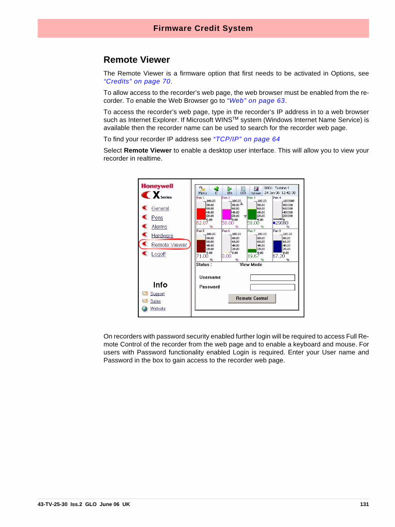
Firmware Credit System
Remote ViewerThe Remote Viewer is a firmware option that first needs to be activated in Options, see“Credits” on page 70.
To allow access to the recorder’s web page, the web browser must be enabled from the re-corder. To enable the Web Browser go to “Web” on page 63.
To access the recorder’s web page, type in the recorder’s IP address in to a web browsersuch as Internet Explorer. If Microsoft WINS™ system (Windows Internet Name Service) isavailable then the recorder name can be used to search for the recorder web page.
To find your recorder IP address see “TCP/IP” on page 64
Select Remote Viewer to enable a desktop user interface. This will allow you to view yourrecorder in realtime.
On recorders with password security enabled further login will be required to access Full Re-mote Control of the recorder from the web page and to enable a keyboard and mouse. Forusers with Password functionality enabled Login is required. Enter your User name andPassword in the box to gain access to the recorder web page.
43-TV-25-30 Iss.2 GLO June 06 UK 131

Firmware Credit System
132 43-TV-25-30 Iss.2 GLO June 06 UK

Section 8: Communication
Comms ConfigurationThere are three main elements to set up for the communication link to work.
• Device configuration for comms. See “Standard Communication Inter-faces” on page 133.
• Software configuration for comms. See “Comms and Trend Manager Pro Suite” on page 135.
• Comms Server software set up. See “Communications Server” on page 143.
Ensure the same communications information is entered into the hardware and the softwarein order for the communications link to work.e.g. Device name and ID., IP address of thedevices.
Install TrendServer from the TrendManager Pro Suite folder and the comms serverand database servers install automatically.
The Minitrend QX and the Multitrend SX devices have flexible and comprehensive com-munication facilities that are essential for the varied and demanding applications requiredfor data acquisition. These devices are fitted with a number of standard communication in-terfaces plus an OPC interface available as a firmware option.
TrendServer software is required to set up and run communications to and from the devic-es to the PC software.
To set up Comms in the device go to “Comms Menu” on page 61.
For Comms connections see “Communications Connections” on page 23
Standard Communication Interfaces
Rear Ethernet Communication port.The rear of the device is fitted with an Ethernet10/100 port, which supports:
• Modbus TCP/IP. See “Modbus” on page 134.
• OPC Server connectivity to third party software. OPC Server connection can be enabled by selecting the OPC option in “Credits” on page 70. For more details on OPC Servers see “OPC Interface - Open Process Control” on page 140
• Web browser. See “Web Browser” on page 142.
Rear RS485 port
• RS 485: 2 wire (half duplex) to support Modbus RTU. See “RS485” on page 23.
Front and Rear USB Communication PortsAt the front and rear of the device are fitted two standard USB communication ports.
43-TV-25-30 Iss.2 GLO June 06 UK 133
Protocols
The USB Host ports will provide an interface for:
• Data downloads.
• Setup uploads.
• External keyboard & mouse
• Barcode reader
• Mass storage device (USB key) or Hard drives (250 GB)
ProtocolsProtocols are an agreed-upon format for transmitting data between two devices. The pro-tocol determines the following:
• the type of error checking to be used
• data compression method, if any
• how the sending device will indicate that it has finished sending a message
• how the receiving device will indicate that it has received a message
The following Protocols available are:
ModbusModbus primarily sends data, no setup information is transferred via Ethernet or RS485ports. The device ID and Serial number is held in the setup and this information is requiredto locate the correct device in TrendServer.
A Modbus Profile Tool runs in the background and a selection of profiles are displayed inthe dialog box (not required for V4 or V5 devices).
Modbus only requires the correct Slave Address to connect, see “Modbus” on page 62. Ifthe device is on the Recorder ID and Serial Number will be transferred, if the device is noton an extra device will appear in the database containing the Realtime data.
Only data can be sent via Modbus. No recorder setups or events are sent for realtime andlogged data.
However, a Modbus interface, such as Modscan 32, can be set up as Modbus master andused to transmit Totals, Digital Input, Digital Output, a Comms Variable (CV) or Messagesto the recorder.
Modbus XModbus X protocol differs from standard Modbus by the reversed byte order of the floatingpoint number.
The Comms Server provides an integrated facility for testing a device to help decide whichmodbus protocol variant to use. See “Edit a Device” on page 151.
Modbus Mapping and Function CodesSee “Appendix J: Function Codes and Memory Maps” on page 215.
134 43-TV-25-30 Iss.2 GLO June 06 UK

Comms and Trend Manager Pro Suite
USB Barcode ReaderUSB ports allow the use of a USB barcode reader.
Comms and Trend Manager Pro SuiteTrendServer software is required to set up and run communications to and from the de-vices and the PC software
TrendServer is part of the TrendManager Pro Suite complete with its own Communi-cations Server function. TrendServer is a fully network aware package which allows dataviewing, archiving and communication over Ethernet and RS485. Ethernet can provide com-munications limited only by PC resources, and RS485 can provide comms for up to 31 de-vices. Included as standard is the ability to e-mail, graph, print and export data. Device datacan be entered into any PC on the LAN (Local Area Networks) and automatically viewed andgraphed at any other PC on the LAN.
TrendServer offers the ability to download and import data communicating using FTP (FileTransfer Protocol) via the Ethernet Interface. To use it you must have a device and a Com-ms card with Ethernet and the FTP option installed.
One of the unique features of the TrendServer software is the Realtime facility in con-junction with the Communications Server. Realtime data can be retrieved from the deviceto a PC via an Ethernet and/or RS485 connection. This data can be viewed, graphed andlogged into the system. Data from the device can be logged to a database and held on adatabase server. Remote servers can be added to the comms server to allow access toremote devices on remote databases not on a local network.
Software InstallationThe Comms server is only available with the TrendServer software. The comms server willauto install with the TrendServer software. For installation instructions for the TrendServ-er software, refer to the TrendManager Pro Suite manual.
UpgradesThere are three software packages available: TrendViewer, TrendManager andTrendServer. If your software upgrade is for the same package the software will automat-ically over-write the previous version. Local database information will not be affected and alldevices data and setups are retained. Any other remote database servers will have to beadded manually.
If you have purchased a different package to what is already installed, the new software willdetect this and only make available the same package. To install a different package, firstun-install the previous version. There is no need to save databases or data, these will notbe lost when un-installing the previous version. Devices and data held on a local databaseare retained for use with the new package as long as it is installed into the same directory.
System SetupTrendServer software is a comprehensive, versatile and easy to use communica-
tions system using established Protocols to transfer data. Individual company require-ments will demand different types of protocols dependant on the size and criteria of thecommunications system network. To help decide which protocol is suitable for eachsetup, see “Protocols” on page 134
43-TV-25-30 Iss.2 GLO June 06 UK 135

Comms and Trend Manager Pro Suite
Data logging and transferUsing the TrendServer software, the device’s details are added on to a database inTrendServer. Once the device has been configured and enabled, data can be retrieved.Data is logged to the internal memory. This data can be exported to TrendServer via:
• Compact Flash/USB (removable media) = transfer setup and data
• Modbus (RS485/Ethernet) = transfer data only
• FTP (Ethernet) = transfer Setup and data
Exporting does not remove the data from the device but when the internal memory buffer isfull the latest data will start to over-write the oldest data.
Data can be imported from devices and logged to a Database, known as ‘Stored and His-toric data’. Databases are managed by a Database Server. The data can be retrieved,graphed, exported to spread sheets, e-mailed or transferred from devices to other data-bases located on Remote Database Servers. Using the Comms Server actual currentdata can be sent from a device straight to the server using Ethernet or RS485 links. Thisactual current data can then be logged to a database and viewed on a graph in real time,this is known as ‘Realtime’ data. Different types of data, realtime, logged and historic datacan be displayed next to each other on a split graph screen. The comms server is used toconfigure logging and manage databases and reflect each devices status. See “Commu-nications Server” on page 143.
PC Ethernet connections
Device and PC Ethernet connections
Hubs or SwitchesHubs and Switches come in all different shapes and sizes. Both are used as a common connection point for devices in a network. They are commonly used to connect segments of a LAN. A hub contains multiple ports and when a packet (Of data) arrives at one port, it is copied to the other ports so that all segments of the LAN can see all packets. Switches work in a similar way but send the data directly from one port to another. On a busy net-work this can be quicker and can have less data collision incidents.
Connect an Ethernet cable from the Ethernet port on the back of the device to the Ethernet hub.Connect another Ethernet cable from the Ethernet port on the PC to the Ethernet hub.
136 43-TV-25-30 Iss.2 GLO June 06 UK
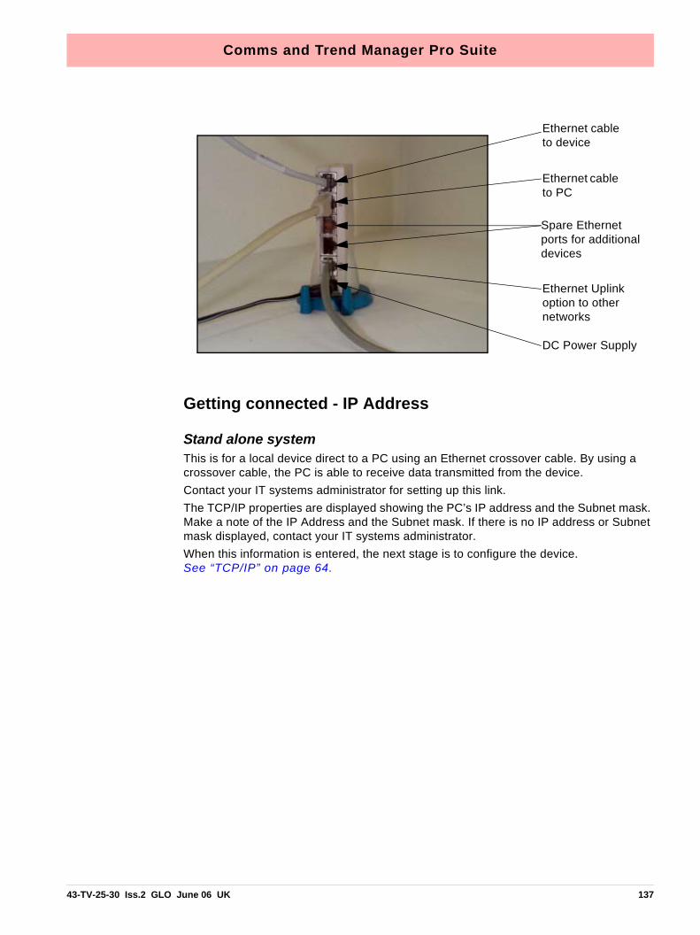
Comms and Trend Manager Pro Suite
Getting connected - IP Address
Stand alone systemThis is for a local device direct to a PC using an Ethernet crossover cable. By using a crossover cable, the PC is able to receive data transmitted from the device.Contact your IT systems administrator for setting up this link.The TCP/IP properties are displayed showing the PC’s IP address and the Subnet mask. Make a note of the IP Address and the Subnet mask. If there is no IP address or Subnet mask displayed, contact your IT systems administrator. When this information is entered, the next stage is to configure the device.See “TCP/IP” on page 64.
DC Power Supply
Ethernet Uplink option to other networks
Spare Ethernet ports for additional devices
Ethernet cable to PC
Ethernet cable to device
43-TV-25-30 Iss.2 GLO June 06 UK 137

Comms and Trend Manager Pro Suite
Local Area Network setupThis is a group of computers and/or associated devices e.g Honeywell devices, that sharea common communications line and typically share the resources of a single processor orserver within a local geographical area (e.g. within an office).
Switch/hub
Uplink (optional) to other networks
Mains
Mains
Figure 8.1 Ethernet hub/switch
138 43-TV-25-30 Iss.2 GLO June 06 UK

Comms and Trend Manager Pro Suite
Links to Remote NetworksCommunications is not just limited to local networks. Devices and databases on remote net-works can be accessed using the TrendServer software via remote comms servers andremote database servers. Remote servers means it is not directly connected to your PC.Figure 8.3 shows an example of two local systems having access to each others remoteservers.
TrendServer 1 can access Comms Server 2 and Database Server 2 and all the deviceswithin the databases on those servers. Similarly TrendServer 2 can access the devicesand databases held on Database 1, and Comms Server 1.
DatabaseServerSoftware
Realtime data from the Comms Server to the TrendServer
CommsServerSoftware
Realtime data from the device to the Comms Server.
Disk data, shown in dotted, is imported from the device to the Database server
Figure 8.2
TrendServer
43-TV-25-30 Iss.2 GLO June 06 UK 139

Comms and Trend Manager Pro Suite
OPC Interface - Open Process ControlOPC Server connection must be enabled in the recorder by selecting the OPC option in “Credits”on page 70. Many types of OPC Server software packages are available and are compat-ible with the recorders. OPC server supports OPC DA version 3 and OPC AE (Alarm andEvents).
OPC limitationsTechnically speaking there are no restrictions on the number of clients that can connect toOPC DA or OPC A&E servers.
Some software limits are in place like:
DatabaseServer 1Software
CommsServer 1Software
CommsServer 2Software
DatabaseServer 2Software
Data-base
Data-baseData-base
Data-base
TrendServer 2
Data-base
Logged to Database
Logged to Database
Figure 8.3 Remote Network
TrendServer 1
140 43-TV-25-30 Iss.2 GLO June 06 UK

Comms and Trend Manager Pro Suite
OPC DA ServerMaximum number of groups that can be added per client is 3.
Maximum number of unique items that a OPC DA server supports is 100. I.e.(Number ofpens + Number of totalisers + Number of communication variable) spread across 3 groupsper client.
Recommended number of clients that can connect a OPC DA server is 3.
OPC A&E ServerNumber of active alarm that is maintained at a given time is 576. Includes pens having activealarms and pens which have normal but unacknowledge alarms if latch enabled.
Recommended maximum number of event subscriptions is 3
An OPC client can be used instead of the TrendServersoftware. It is a user software ap-plication for realtime interface between servers and clients. Information from our commsserver, which is OPC compliant, uses an industry standard method of uniform data inter-change. The OPC client can then export realtime communications to other applications,eg. Microsoft™ Excel.
How OPC worksWhen data acquisition devices conform to the OPC standard, you can use them with anyOPC-enabled software application. And vice versa. You can therefore easily combine differ-ent devices from different manufacturers in one system. OPC gives you the freedom to addnew hardware from third-party vendors to existing set-ups, or to replace a device, withoutworrying about compatibility with your chosen software. Select the hardware and softwareyou want for a particular application.
The measurement and control hardware, such as a recorder, provides front-line data acqui-sition. As soon as the hardware device has collected the data it makes it available to soft-ware applications running under Windows. It presents the data according to the OPCstandard, and is thus known as an OPC server. Each OPC server offers data in the sameway. If the software application can understand the OPC format it can therefore access datafrom any OPC server device, making individual drivers for each piece of equipment obso-lete.
OPC-enabled software include spread sheets, databases, virtual instruments and SCADA(supervisory control and data acquisition) interfaces. These applications are known as OPCclient software.
Each OPC server can simultaneously provide data for any number of OPC clients. Likewisemultiple clients can at the same moment access any server: a robust method of communi-cation. With OPC, measurement and control systems can share information and co-operatewith other installations across factories, offices, laboratories, etc. The same data is thereforereadily available to engineering, maintenance, management...in fact to anyone that requiresup-to-the-minute data on which to base their decisions.
OPC allows "plug-and-play". All OPC devices will connect together and immediately workwith the OPC client software. This has the potential to massively reduce installation and sys-tem configuration time. It also means that you can add devices without shutting down exist-ing systems.
OPC offers the following:
• Combine different devices from different manufacturers in one system
• Reduce installation time
43-TV-25-30 Iss.2 GLO June 06 UK 141

Comms and Trend Manager Pro Suite
• Add devices without stopping existing software and systems
• Quickly replace a device from one vendor with one from another
• Share information around networks
• Device drivers rendered obsolete
• Factory, laboratory and office applications can all access the same data
• Reliable data as any number of OPC software applications can simultaneously read a device
• Single, industry-standard, data interface
OPC Clients
An OPC client can be used instead of the TrendServer software. It is a user software appli-cation for realtime interface between servers and clients. Information from our comms server, which is OPC compliant, uses an industry standard method of uniform data inter-change. The OPC client can then export realtime communications to other applications, eg. Microsoft™ Excel.
Web BrowserThe Web Browse function can be enabled/disabled from the recorder. The web button canbe password protected if passwords are enabled. See “Web” on page 63.
To access the web page, type the device’s IP address in to a web browser such as InternetExplorer. If Microsoft™ WINS system (Windows Internet Name Service) is available then thedevice name can be used to search for the device web page.
A Login Screen will appear for users with Password functionality enabled. Enter the pass-word protected User name and Password supplied to log in here. For Users without Pass-word security just choose a language option to access the web page.
For Remote Viewer access see “Remote Viewer” on page 131.
To find your device IP address, see IP Address on “TCP/IP” on page 64 or go to the Sys-tem, General screen in the “Status Menu” on page 96.
Internet Security SettingsTypes of web browser for use with the Remote Viewer include Internet Explorer 5 andabove.
Figure 8.4, “Internet Security,” on page 143 shows an example from Internet Explorer6 on a Windows™ XP machine. The settings shown are for Internet access. If the device isto be accessed in an intranet scenario then the same has to be done for Local intranet op-tion.
Firewall settings If this device is sitting on an enterprise network with a firewall in place then the firewallshould be configured to allow all requests on port 80 and port 976 (for remote control ac-tiveX).
Access to the firewall settings will differ depending on what firewall is installed.
142 43-TV-25-30 Iss.2 GLO June 06 UK

Communications Server
Communications Server
Comms Server OverviewThe Comms Server and the Database server will automatically become active when theTrendServer software is running. Refer to the TrendManager Pro Suite Software Manual,Installation instructions. The Comms server will enable the user to:
• Monitor the status of communications with a device on any serial port, up to 8 ports and an Ethernet connection.
• Set up local and remote databases
• Set up local and remote servers
• Modbus protocols supported on Ethernet and Serial ports
• Enable and disable ports
• Add, edit and remove devices
• Log to database or client connections, local or OPC client.
The comms server will appear as an icon in the system task bar in the bottom right of thePC screen.
Figure 8.4 Internet Security
43-TV-25-30 Iss.2 GLO June 06 UK 143

Communications Server
The Communications Server appears as an icon in the Windows™ systembar at the bottom right of the screen. Double click or right click to open, loadsautomatically with TrendServer. The comms server manages the commu-nications status of devices on a serial port (RS485) or through an Ethernetconnection. Only Modbus protocol is available for X Series devices, see
“Modbus” on page 134.
Devices are held on databases and the databases are held on servers. By accessing othercomms servers remotely it is possible to receive data from other devices held on databaseson other servers - known as remote servers, Figure 8.3 on page 140.
The comms server uses IP Addresses to locate devices on local and remote servers. AllLogging configuration for comms logging and logging to a database is set up from the Com-ms Server.
The Comms Status shows all the activity of devices, Communications ports, Databases andDatabase Servers. The window to the left displays the areas controlled by the comms serv-er, the database servers and the communications ports. The display area(s) to the right willdisplay details of any item selected in the left window. Depending on what has been selectedthe right window will split in two to give logging information. Items listed in the left windowthat have a + sign against them contain other items, click on the + sign to reveal the list ofitems contained within. The + sign will change to a - sign when all the items are displayed.To close the list, click on the - sign.
AdministrationThe Administration button appears in the top left of the comms server, it contains:
• Shutdown Server - From here the comms server can be shut down this will disconnect the comms server, it will also shutdown the database servers at the same time.
• Preferences - The General Settings tab has an option to minimise the Server when it isopened. The Diagnostics option that will produce an additional tab to the bottom window,this will display properties and values of a selected device. Send Recorder Events is anoption that will send any event data when an export data function is performed. The ClearSetup Cache button will remove all setup files. Network Settings is for PC’s with morethan one network card fitted to access devices on other networks. The network cards aredisplayed here for selection. If the ‘Use NIC Default IP Address Selection’ is ticked then thefirst network card that was added to the list will always be selected.
144 43-TV-25-30 Iss.2 GLO June 06 UK

Communications Server
• Preferences - The Timing Setups tab displays the current timings for the current com-munications setup. These entries should be configured correctly and not require anychanges by the user.
• Contents - Enables the Help files.
• About Communications Server - Gives the version of the software.
Add a new Device to a communications port.Use this icon button as one way of adding a device to Communications port. Otherways of adding a device are to right click on the desired port in the left window ie.
Ethernet, and select the Add Device option. Or select a comms port in the left window, rightclick in a clear space in the top window and select Add Device.
Configure Database LoggingUse this icon button to configure a device for logging channels to a database. Oth-er ways to configure logging are to right click on a comms port or a device in the
left window, or a device in the top window displaying the device for that port.
Connect to a new Database ServerUse this icon button to connect to a database server, either a Local, or RemoteServer that has been added to the database servers list. Connection can be made
by selecting ‘Database Servers’ in the left window and then right clicking in a clear spacein the top window displaying the database servers list.
43-TV-25-30 Iss.2 GLO June 06 UK 145

Communications Server
Comms Server Status Screen.
Database ServersThe Database Server will list databases and display the devices within each database asthey are added. Click on any of the database servers or the database within and details ofthat item is displayed in the main window. The main window will split to give additional infor-mation for databases showing comms port and device details.
Devices are added to the comms server through the Communications port, the device canthen be configured for logging. The devices appear in the database and these databasesare held within database servers. Figure 8.5 on page 146, shows the comms statusscreen, in the left window from the top is displayed Database Server, Local and remote da-tabase and devices held on the Local database.
Connected databases are displayed with a green icon. If the database is in red it is not con-nected, check the IP Address and Device ID are correct and a protocol has been selectedon the device. Un-tick and then tick the active box on the comms server to restart the data-base connection.
This section looks at the Comms Server’s main elements displayed in the Status Screen:Database Servers, Local and Remote Servers, Databases, Communication Ports, Data-base logging and Client connections
Figure 8.5 Server, Databases and Devices list
146 43-TV-25-30 Iss.2 GLO June 06 UK

Communications Server
Remote database servers can be added to the list to enable access to devices held in otherdatabases on a remote database server in another location. To connect to a remote data-base server the IP address must be known of the PC where the databases server is held
Items with a ‘+’ sign signifies there are items listed within. Click on the ‘+’ sign to activate/expand.
• Listed under the Database Servers are a list of Servers.
• Listed under each Server are the Databases.
• Listed under each Database are the devices
.
The bottom window has three actions, Client connections, Database logging and Diag-nostics. When a device is selected from the top window details of the device’s activity isdisplayed here. Device logging to a database will display details in the Database logging tab.Realtime data will display in the Client connections tab. The Diagnostics tab can be activat-ed by going to Administration, Preferences and ticking the Show Diagnostics box, this willdisplay properties and vales of a selected device.
Communication PortsThe Communication Ports is a list of ports available, COM1 to COM8 and Ethernet. As de-vices are added they are displayed under the port name. Click on Communication Ports todisplay a list of all the ports in the main window, tick the required port to enable. Click on aport and the main window splits into two windows, top and bottom.
The top window displays details of the devices using that port including device ID No., de-vice Name, Mode and Status show if the device is connected, how many Channels thedevice has enabled, an Active button to activate the device and the device’s IP Address.As devices get added to each port they will display in the list for that particular port.
This is the Database Server icon.
This is the Database icon
43-TV-25-30 Iss.2 GLO June 06 UK 147

Communications Server
Client ConnectionsRealtime comms data from the device will only display on the comms server communica-tions status screen when realtime data is active on either the server software or by using anOPC client. Once data is active on a client connection, this window will display details of thedevice selected in the top window: its Destination or where the information is going to,Source or origin of the data (channel or event), Rate and Type of data sampling being com-municated. See “OPC Interface - Open Process Control” on page 140. and “OPC Cli-ents” on page 142.
Database LoggingThis tab will display information on what is currently being logged to a database for the de-vice that is selected in the top window: its Destination or where the information is going to,Source or origin of the data (channel or event), Rate and Type of data sampling being com-municated.
Client connections tab displays realtime comms running on the server software, for the recorder selected in the top window.
The Database logging tab displays the pens logging to a database for the recorder select-ed in the top window.
A third tab, Diagnostics, can be enabled using the Administration button, and selecting Preferences.
148 43-TV-25-30 Iss.2 GLO June 06 UK

Communications Server
Comms Server SetupThe comms server software can be run independently to the main application software bycreating a shortcut to the Startup folder. If over-writing a previous version of X Series commsserver, only the local server will retain the database information and load all the devices andsettings from the databases. Any other remote database servers will have to be added man-ually.
Comms Server - new userUsing the comms server from scratch requires:
1. Add a new device to a Communications port. Devices will appear under the Communi-cations Port, when selected, in the left window and will appear in the initial database on the local comms server. See “Add a Device” on page 150.
2. Click on ‘Communication Ports’ in the left window to display a list of the ports in the main window. Tick the port that the device has been added to. See “Communication Ports” on page 147.
3. For a realtime connection, check device connection status by clicking on the device under its comms port in the left window to display the device status in the top main win-dow. Green LED’s will show a realtime connection is made. If grey LED’s are showing and the device displays ‘Unconnected’ and if Red LED’s display then there is a problem with connection.
4. The data from this device can now be logged to a database by using the Configure log-ging screen and setting up channels for logging with the log rate and type and setting up a destination database. See “Logging Configuration” on page 151.
5. When the realtime data is being run, eg. graphed to the application server software, or an OPC client, this will enable the bottom window that will display details of the data.
Add a DatabaseTo add a database to a server, right click on the server eg. Local Server, select Add Data-base and complete the dialog box details for the name and description of the device.
Add a Database Server
1. Use the database icon with a + sign in the top left of the comms server window.
2. Right click on Database Servers in the top left window
Connect to a Database Server
1. Select ‘Database Servers’ in the left window and then right click on the server to be connected in the servers list in the main window.
2. Connect to database server dialog box will appear, enter an IP address and a descrip-tion to identify the database server.
Delete a Database Server
1. Right click on the database server to be removed and select the delete option.
2. A dialog box will appear with the IP address of the database server to be deleted. If this is correct, click on OK.
All database servers can be removed except for the Local Server.
43-TV-25-30 Iss.2 GLO June 06 UK 149

Communications Server
Add a DeviceThere are three ways to add a device, they all deliver the same dialog box:
1. Use the device icon in the top left of the comms server window.
2. Right click on a selected Comms port in the left window, COM1 to COM8 or Ethernet and select Add Device from the resulting menu.
3. Select a Comms port and right click in a blank space in the top window and select Add Device from the resulting menu.
All these methods will produce the Add Device Details box. Areas of the box become greyedout as the selections are made.
Protocol - For active Modbus devices, the recorder name and protocol variant can bechanged (modbus vs Modbus X). For an inactive Modbus device the device profile can alsobe changed.
Profile Name - The system creates Modbus profiles from an imported setup or logged dataand creates a profile including information for pen, scale, units etc. If the Profile Name win-dow is empty it means that no setup or data has been imported into Comms server. The pro-file Name is made up from the Recorder name, Type and ID number. Once the setup or datahas been imported it will display in this window, no need to restart Comms Server.
Communications Port - Choose between Ethernet or RS485 for COM ports 1 to 8. Thismay already be entered depending on how you have chosen to add the device.
IP Address - Go to Main Menu > Status > System > General. In this list is the recorder IPAddress
Slave ID - This is a unique Modbus ID/Address used by the recorder to identify Modbusmessages. Applications that talk to the recorder with Modbus will need to know this numberto return messages to the device. Comms Server must the same number must match.
Recorder Name - This is the name displayed in the top right any process screen on the re-corder or found in Main Menu > Configure > Setup > Edit Setup > General > Ident > Name.
150 43-TV-25-30 Iss.2 GLO June 06 UK

Communications Server
Status - This will automatically enable the designated port and the device will become ac-tive. This can be activated later from the main Comms Server screen.
The Test button gives information regarding which Modbus protocol variant that is beingused. The test box shows both Modbus and Modbus X readings being received to help de-termine which protocol is correct for this device.
Edit a DeviceSelect the Comms port containing the device for editing and right click on the device eitherin the left or top window. The Edit Device Details dialog box will appear showing the config-uration for comms with that device. Any fields not greyed-out can be changed. For Ethernetdevices the IP address can be changed. Any device can be made active or inactive fromhere. For active Modbus devices, the recorder name and protocol variant can be changed(modbus vs Modbus X). For an inactive Modbus device the device profile can also bechanged.
The Test button gives information regarding which Modbus protocol variant that is beingused. The test box shows both Modbus and Modbus X readings being received to help de-termine which protocol is correct for this device.
Click on the OK button and the changes are saved.
Delete a DeviceSelect the Comms port containing the device to be deleted and right click on the device ei-ther in the left or top window. Select Delete Device from the resulting menu. The Delete De-vice Details dialog box will appear showing the details of that particular device. Check thisis the correct device for deletion, then click on the OK button and the device is removed,otherwise the operation can be cancelled.
Logging ConfigurationThis screen configures channels for logging from a device to a database. It can be accessedin several ways.
1. Use the Configure Database Logging icon at the top left of the screen and select Con-figure Logging from the resulting menu.
2. Right click on ‘Communication Ports’ in the left window and select Configure Logging from the resulting menu.
3. Right click on the comms port and select Configure Logging from the resulting menu.
4. Right click on the device and select Configure Logging from the resulting menu.
Any of these will display the Logging Configuration box. If this screen is selected from eithera comms port or a device then the comms port information will already be inserted. If thescreen is selected from the icon or Communications Port heading then the comms port willneed to be assigned. Select the device ID number (if necessary), from the drop down menu.
The next section is Database Configuration, a list of connected database servers and a listof databases that are currently being logged to. In this section is a window showing thechannels available to be logged. As channels are selected from this window, three additionalbuttons become active: ‘Add Channel selection’, select each channel for logging, ‘Add allChannels’ for logging and Clear Channel selection.
43-TV-25-30 Iss.2 GLO June 06 UK 151

Comms Server Database
Add Channels for LoggingAs each channel is selected, or all channels depending on the button selected, the LoggingChannel Configuration box appears so the Log Rate and Type of logging can be set for eachchannel individually or all channels.
When the channels have been selected they will appear in the bottom window, click on Ap-ply to enable the channels to log. Once the channels are in the ‘Channels logging to selecteddatabase’ window they can be selected and the Edit and Delete button become active. TheEdit button allows the logging rate or type of logging to be changed.
There is also a Database Events Logging box that can be ticked that allows any events tobe logged to the database.
Summary of Logging Changes - If any changes are made using the Edit button, the Sum-mary of Changes button becomes active, this will show the last changes made to any of thechannels for this configuration only.
The Delete button will take the channel out of this window and put it into the window showingavailable channels for logging, logging will stop for this channel.
Comms Server DatabaseThis is the database icon which will appear in the bottom right of the screento show that the TrendServer software is running with the Database serveractive. Loads automatically with TrendServer.
152 43-TV-25-30 Iss.2 GLO June 06 UK

Comms Server Database
System SetupThe system can be set up two ways.
1. For customers who are setting up in preparation for the arrival of their devices. Using the TrendServer and Comms Server software, create a database for the device(s) and configure each device for logging using the comms server. When the devices are in place and connected check the IP address (for Ethernet devices only) and the device ID is correct.
2. For larger networks - Set up the hardware first noting each devices ID and IP address. Use the comms server software to set up the devices on a database and configure log-ging for each device. The devices will need to be set up on the TrendServer soft-ware before the connections can be tested and become active.
43-TV-25-30 Iss.2 GLO June 06 UK 153

Comms Server Database
154 43-TV-25-30 Iss.2 GLO June 06 UK

Section 9: PC Software Suite
The TrendManager Pro Software SuiteThe TrendManager Pro Software Suite complements the capabilities of the “X Series” recordersby providing the benefits of viewing, configuration, network communications, database management,data analysis and report generation using a personal computer. It ties the process together, providingfor real-time or FTP communications with the recorders through a Local Area Network (LAN).
TrendViewerThis is the standard software provided with the recorder that displays and prints data imported fromthe storage media used by the recorder.
TrendManager ProThis is an advanced data analysis/archiving software package, providing full configuration of the re-corders. TrendManager Pro is a stand-alone package that delivers to the user total recorder con-figuration, allowing the user to archive, graph, print and export data. TMP also allows files to beexported using comma separated variables (CSV) format, that can be imported into most computersoftware.
TrendServer ProThis is a fully network aware software package for real-time viewing and archiving of data with com-munications to the recorder. It supports all the capabilities of TrendManager Pro plus real-time dataacquisition, FTP (file transfer protocol) and web browser access. TrendServer Pro provides securemulti-level, multi-user access to the recorder data by various departments with security. Standard fea-tures of TrendServer Pro include data archive tools E-mail set up and alarming, graphing, print im-port and export data facilities.
TrendManager Pro with OPC Server - provides the same functions as the TrendServer Pro butincludes the added function of an integrated OPC Server to allow easy interfacing to third party HMIsoftware packages that support an OPC Client. This provides a real-time interface between serversand clients.
Database Management ToolDatabase Management Tool - this software application works with TrendManager Pro andTrendServer Pro to provide safe administration of data with tools to archive, sort, move, copy anddelete the data stored in local and remote databases. The Database Management Tool software is supplied with TrendServer Pro
X Series Screen DesignerX Series Screen Designer - is a separate software package that enables the user to design uniquedisplay layouts for transfer to the recorder’s screen. Screen layouts can be created using any combi-nation of indicators such as Trending Charts, Digital Panel Meters (DPM) and Bar graphs. Flexibilityallows each type of indicator to have elements of its appearance changed to create an individual pres-entation. The X Series Screen Designer software package is compatible with Minitrend QX andMultitrend SX recorders. Layouts can be transferred on to single or multiple recorders of the sametype, which contributes to continuity and standardization of process data. For use with X Series re-corders only.
Firmware can be upgraded from the web site at www.XSeries-info.net.
43-TV-25-30 Iss.2 GLO June 06 UK 155
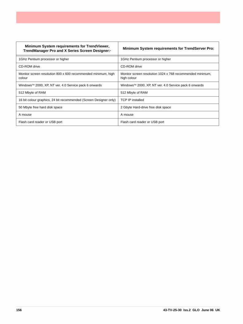
Minimum System requirements for TrendViewer, TrendManager Pro and X Series Screen Designer:· Minimum System requirements for TrendServer Pro:
1GHz Pentium processor or higher 1GHz Pentium processor or higher
CD-ROM drive CD-ROM drive
Monitor screen resolution 800 x 600 recommended minimum, high colour
Monitor screen resolution 1024 x 768 recommended minimum, high colour
Windows™ 2000, XP, NT ver. 4.0 Service pack 6 onwards Windows™ 2000, XP, NT ver. 4.0 Service pack 6 onwards
512 Mbyte of RAM 512 Mbyte of RAM
16 bit colour graphics, 24 bit recommended (Screen Designer only) TCP IP installed
50 Mbyte free hard disk space 2 Gbyte Hard-drive free disk space
A mouse A mouse
Flash card reader or USB port Flash card reader or USB port
156 43-TV-25-30 Iss.2 GLO June 06 UK

Section 10: Spares List
Minitrend QX Recorder
16 5
3 1 4 2
24
10 499
45
19
43-TV-25-30 Iss.2 GLO June 06 UK 157

52
20 to 50VDC/20 to 30VAC Input Instrument power
24X TX Power Supply
Analogue Input or Pulse Input
Alarm/Digital IO
CJC SensorAnalogue Input, Analogue Output
7
19
Common Relay Output
27
23
RS485
RS485USB host
Ethernet
54
158 43-TV-25-30 Iss.2 GLO June 06 UK

Table 10.1 :
Minitrend QX - Spares
1 51453012-502 QX Processor Board Assy
2 51453006-50151453006-50251453006-503
QX Analogue Input 4CH AssyQX Analogue Input 6CH AssyQX Analogue Input 8CH Assy
2 51453027-50151453027-502
QX Analogue Output 2CH AssyQX Analogue Output 4CH Assy
2 50001017-502 QX Pulse Input 4CH Assy
3 51453009-501 QX Mother Board Assy
4 51453018-50151453018-502
QX Digital I/O 8CH AssyQX Digital I/O 16CH Assy
4 51453021-50151453021-502
QX Relay Alarm 4CH AssyQX Relay Alarm 8CH Assy
5 51453015-50151453015-50251453015-503
QX Power Supply AC MainsQX Power Supply AC/TXQX Power Supply 20V/55VDC/20-30VAC
7 50013945-501
50013945-502
QX Bezel/Touch Screen and Std Nema 3/IP55 Door AssyQX Bezel/Touch Screen and Nema 4X/IP66 Door Assy
Includes Bezel, Touch Screen and Door Assy
9 50003508-501 QX Nema 4X/IP66 Door
10 50009118-501 QX Std Nema 3/IP55 Door
16 50006685-502 QX Bezel/Touch Screen/Display As-sembly NEMA 4X/IP66
Includes Bezel Touch Screen Assy, Door, Display, Speaker, In-verter, cables and Mounting Bracket
19 51453076-501 QX 5.5” Display
23 50001782-501 QX / SX Speaker
25 50016276-501 QX Vutronik Adaptor Assy Not shown
24 51453071-501 QX Case and Back Plate Assy
27 51453077-501 QX Inverter and Cable Assy
28 50006787-501 QX / SX Battery (Kit of 5)
43-TV-25-30 Iss.2 GLO June 06 UK 159

29 50001011-50250001011-50350001011-50450001011-50550001011-506
Compact Flash card 64MbCompact Flash card 128MbCompact Flash card 256MbCompact Flash card 512MbCompact Flash card 1GB
Not shown
43 51453071-502 QX Case, Handle and Terminal Cover Not shown
44 50005224-501 QX Rear Terminal Cover Not shown
45 50017150-501 QX Left & Right Hand Chassis kit
48 30755050-502 QX Mounting Hardware kit (2 Mounting Brackets)
Not shown
49 51453083-501 QX Panel Gasket
52 51453038-501 Stylus Kit Black (pack of 5)
53 50013947-501 Connector kit (2 of each connector type)
Not shown
54 50017179-501 QX 5.5” Backlight kit of 2 Not shown
50017290-501 Touch Screen Protector (kit of 5) Not shown
50017181-501 QX/SX Blanking Plate for I/O Slots (2) Not shown
51452129-501 10 Ohm Resistors Pack of 8 Not shown
50001251-501 QX Portable Case Not shown
Table 10.1 :
Minitrend QX - Spares
160 43-TV-25-30 Iss.2 GLO June 06 UK
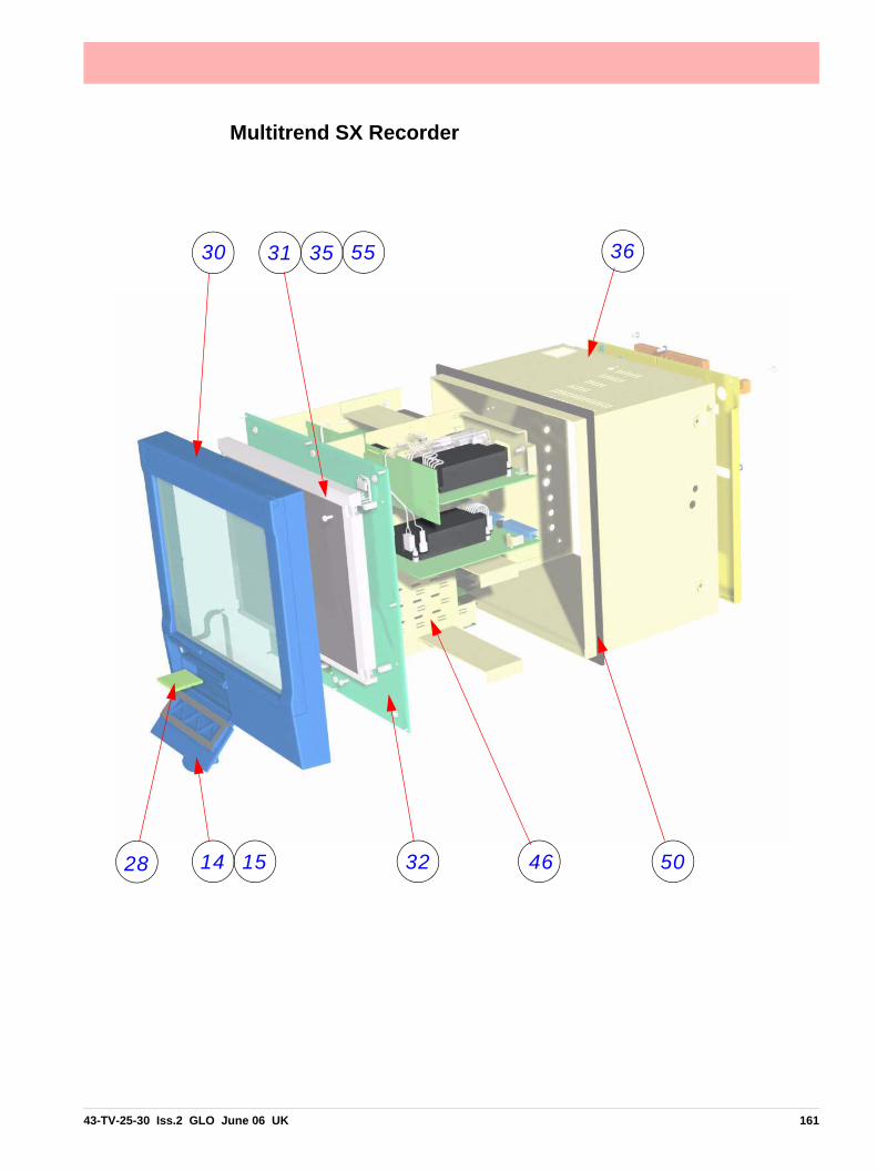
Multitrend SX Recorder
14 15 32 46 50
30 31 35 36
28
55
43-TV-25-30 Iss.2 GLO June 06 UK 161

52 11 23
33 39 5 6 RS485 USB host
Ethernet
1
2
3
4
162 43-TV-25-30 Iss.2 GLO June 06 UK

24V TX Power Supply Output
RS 485
Alarm / Digital IO
Analogue Input or Pulse Input
CJC Sensor
Analogue Input or Analogue Output
20 to 50V DC / 20 to 30VAC Input Instrument supply
Common Relay Output
43-TV-25-30 Iss.2 GLO June 06 UK 163

Table 10.2 :
Multitrend SX - Spares
1 51453012-501 SX Processor Board Assy
2 51453006-50151453006-50251453006-503
SX Analogue Input 4CH AssySX Analogue Input 6CH AssySX Analogue Input 8CH Assy
2 51453027-50151453027-502
SX Analogue Output 2CH AssySX Analogue Output 4CH Assy
2 50001017-502 SX Pulse Input 4CH Assy
3 51453024-501 SX Mother Board Assy
4 51453018-50151453018-502
SX Digital I/O 8CH AssySX Digital I/O 16CH Assy
4 51453021-50151453021-502
SX Relay Alarm 4CH AssySX Relay Alarm 8CH Assy
5 50001182-50150001182-502
SX Power Supply AC MainsSX Power Supply 20-50VDC/20-30VAC
6 51453030-501 SX Transmitter Power Supply board
11 50013946-501
50013946-502
SX Bezel/Touch Screen Std and Nema 3/IP55 DoorSX Bezel/Touch Screen and Nema 4X/IP66 Door Assy
Includes Bezel, Touch Screen and Door
14 50009119-501 SX Std Nema 3/IP55 Door
15 50003590-501 SX Nema 4X/IP66 Door
23 50001782-501 QX / SX Speaker Assy
27 50006787-501 QX / SX Battery (kit of 5) Not shown
28 50001011-50250001011-50350001011-50450001011-50550001011-506
Compact Flash card 64MbCompact Flash card 128MbCompact Flash card 256MbCompact Flash card 512MbCompact Flash card 1GB
Not shown
30 50006809-502 SX Display/Bezel/Touch Screen Assy NEMA 4X/IP66
Includes Bezel, Touch Screen and Display
31 50004352-501 SX 12.1” Display
36 51453098-501 SX Case and Back Plate
39 50004348-501 SX Inverter and Cable kit
164 43-TV-25-30 Iss.2 GLO June 06 UK

41 51453098-501 SX Case and Back Plate Not shown
42 50005458-501 SX Rear Terminal Cover kit Not shown
46 51453095-501 SX Chassis kit
50 50000871-501 SX Panel Gasket
51 50004292-501 SX Panel Clamp Assy (Qty 2) Not shown
52 51453038-501 Stylus Kit Black (pack of 5)
53 50013947-501 Connector kit (2 of each connector type)
Not shown
55 50017180-501 SX 12.1” Backlight Not shown
50017290-502 SX Screen Protector (Kit of 5) Not shown
51452129-501 10 Ohm Resistors Pack of 8 Not shown
50017181-501 QX/SX Blanking Plate for I/O Slots (2) Not shown
50001249-501 SX Portable Case Not shown
Table 10.2 :
Multitrend SX - Spares
43-TV-25-30 Iss.2 GLO June 06 UK 165

166 43-TV-25-30 Iss.2 GLO June 06 UK

Section 11: Instrument Care and Maintenance
The X Series range of recorders contains no parts serviceable by the user, except for a fuse on the DC power supply, see “Fuses” on page 12.
In the event of a recorder failure contact your nearest Service Department (or an author-ised agent) to arrange for the return of the unit for repair.
Cleaning InstructionsThe recorder’s touch screen can be temporarily disabled for cleaning, see “Clean Screen”on page 86.
Cleaning the unit should be done with a soft lint cloth and warm soapy water or screen cleaner recommended for use on a PC. Solvents and prolonged exposure to detergents can cause damage to the front panel. It is recommended that any cloth used for cleaning is damp but NOT wet, to avoid water collecting in the unit.
For Nema 4X /IP66 rated units refer to the Nema 4X standards.
Backlights1. At room temperature and full brightness the backlight MTTF is 55,000 hrs.
1. MTTF is defined as the time at which 50% of a batch of backlights remain in excess of half their original brightness i.e. a display has a greater than 50% chance of being half its original brightness after 55,000 hrs for the QX and 43,000 hrs for the SX when used at 100%. Maximum luminosity 400 cd/m2. Reducing the brightness can signifi-cantly improve the life of the backlight.
2. At extended temperatures these times are reduced.
3. The backlight is a consumable item, and will NOT last forever.
4. A maintenance schedule of exchanging backlights should be every 5 years to maintainthe optimal disk clarity.
Operating TemperatureOperating temperatures are described in “Specification Tables” on page 173. Pro-
longed operation at temperatures over 50 °C will accelerate degradation of the displaybacklight.
If the unit has been moved from a cold environment into a warm one, ensure that theunit has reached a minimum temperature of 12 °C or is left to stand for 1 hour at roomtemperature before applying power, to ensure no condensation remains in the unit.
Touch ScreenCare should be taken with the touch screen when handling the unit. Sharp and hard
objects may pierce the touch screen and damage the display. Only use the stylus pro-vided for screen selection.
Clean the screen using a suitable touch screen cleaner. Abrasive materials will dam-age the touch screen.
Protective Screen covers are available to provide additional protection against abrasivematerials. See “Section 10: Spares List” on page 157.
43-TV-25-30 Iss.2 GLO June 06 UK 167

Calibration
CalibrationIt is recommended that Recorder calibration is checked at least every year, or in accord-ance with your industry regulations, to ensure maximum accuracy. See “Calibration” on page 71.
168 43-TV-25-30 Iss.2 GLO June 06 UK

Section 12: Technical Data & Specifications
Field IO Specification
Analogue Output Each recorder is capable of supporting analogue output function. The AO card is availableas a 2 or 4 channel option, and will plug into any of the analogue input slots.
Analogue Outputs are used to support:
• Re-transmission of Analogue Input values
• Re-transmission of Math Results
• Re-transmission of Process values
• Control Outputs
Analogue Output Specifications
• Resolution - 0.002% or better
• Accuracy - +/- 0.1% 0-500ohm load, +/- 0.25% 500ohm - 1Kohm load
• Maximum load resistance - 1Kohm
• Isolation - 300V AC
• Outputting - 0 to 20mA or 4 to 20mA (over range capability to 21mA)
• Update rate - 250mSec per channel
Pulse Input Card The Pulse Card is available as an option, and will fit in slots normally allocated to AI cards.The frequency output from the card is fed to the Maths block (as per other inputs) and isrepresented by HPULn (where ‘n’ is from 1 to 4, when the card is fitted in the top slot)
• Frequency - 1 Hz to 25kHz, this will update once per second
• Inputs - 4 x isolated inputs.
43-TV-25-30 Iss.2 GLO June 06 UK 169

Analogue Input
Analogue Input
User Defined Maximum Input RangesFor values entered for the Range Type in the “Analogue In Menu” on page 44.
Alarm/Digital Input SpecificationMinitrend QX recorder has one ‘slot’ for digital inputs and alarm relay outputs on one card.All alarm card channels provide 240V AC isolation channel to channel and channel to re-corder. Digital I/O channels will provide isolation to 100V AC test voltage (not for mains con-nection).
The Multitrend SX recorder has three available expansion slots for Digital Input/Alarm Re-lay output cards.
Inputs are automatically debounced to remove switching oscillations. All Digital Inputs arevolt free contacts, and are sampled at 10Hz max.
Alarm/Relay Output Card OptionsThere are two card options, split into two types:
4 Channel Alarm Card120/240 VAC 3 Amps rated (resistive load). The relay contacts are form C (NO, NC) andincludes suppression.
8 Channel Alarm Card120/240V AC 3 Amps rated (resistive load). Two channels on the 8 Alarm card, can be usedas digital inputs. The relay contacts are form C (NO, NC) and includes suppression. The 8& 2 Alarm Relay card, this 8-channel card will have 8 mains rated relays, of which 2 of the8 channels can be configured for use as digital inputs.
Table 12.1 : Analogue In Ranges
Preset Ranges Maximum Voltages Preset Ranges Maximum
Voltages
50V 52V 1000mV 1.1V
25V 26V 500mV 600mV
12V 13V 250mV 300mV
6V 6.5V 100mV 150mV
3V 3.25V 50mV 75mV
1.5V 1.6V 25mV 36mV
0.6V 0.8V 10mV 18mV
0.3V 0.4V 5mV 9mV
170 43-TV-25-30 Iss.2 GLO June 06 UK

Alarm/Digital Input Specification
Latched or Single PulseThe relay outputs can be set by the user to be either Latched or Single Pulse.
LatchedA latched relay will maintain in its active state until the trigger source has returned to a nonalarmed state, or a second Event has been activated to disable the relay.
Single PulseThe relay will go active for a period of time, specified by the user, then return to a non activestate. The time out period remains independent of the length of time the active state re-mains.
Single Pulse Relay SettingsUser can specify Pulse length in seconds from 0.1 (100ms) to 6480 (108 minutes) in 0.1 sec-ond increments.
Fail SafeEach relay channel can be independently selected with the fail safe option. This will invertthe state of the relay output. With Failsafe Off normally open (NO) relays have open contactswhen the power is off, and open contacts when there is no active alarm. The contacts willclose when an associated alarm goes active. With Failsafe On, normally open relays haveclosed contacts when the recorder is powered on and there are no open active alarms, andthe contacts open with an alarm active or when the power is removed. See “Failsafe RelayPositions” on page 172.
Relay Output SpecificationThe Minitrend QX recorder will provide the ability to have at least 1 relay output for eachanalogue input (i.e. 16). Multitrend SX recorder will also provide at least one relay outputfor each analogue input (i.e. 48), there are three available slots for Digital inputs/ Relay Out-puts.
Common Alarm Output (standard)The common alarm output include a single ‘common’ alarm relay on the power board. Thisrelay is the same rating as those on the 8 & 16 Digital I/O cards. This relay is NC (normallyclosed) and can be activated by any alarm. This relay will close when power is removed.This relay is identified as “Fixed” in the relay output pick lists.
• Rating - 24Vdc 1A Resistive Load
Digital Input CardsThree options for digital inputs are available
8 Digital Inputs 8 Digital I/O card, this 8-channel card allows the user to configure each channel to be eitherrelay output or digital input. 24V DC 1 Amp rated (resistive load). Each channel on this cardcan be used as either a relay output or digital input. The relay contacts are form A (NO) andincludes suppression.
43-TV-25-30 Iss.2 GLO June 06 UK 171

Alarm/Digital Input Specification
16 Digital Inputs16 Digital I/O card, this 16-channel card allows the user to configure each channel to be ei-ther relay output or digital input. 24V DC 1 Amp rated (resistive load). Each channel on thiscard can be used as either a relay output or digital input. The relay contacts are form A (NO)and includes suppression.
Digital Input FunctionsThe digital inputs can be used for the following actions;
• A Digital contact on an input can be used to enable or disable one or any combination of alarms
• Can be used in Maths expressions
• Can have current status indicated on DPMs, Bars and Charts
Failsafe Relay Positions
Table 12.2 :
QX and SX Relay Positions (no alarms active)
NormalRelay Output States
NO NC
Power On Open Closed
Power Off Open Closed
FailsafeRelay Output States
NO NC
Power On Closed Open
Power Off Open Closed
172 43-TV-25-30 Iss.2 GLO June 06 UK

Specification Tables
Specification Tables
Specification Design AttributesDigital indicators and Display QX Recorder
Display size and Type: 5.5” diagonal, Digital Colour LCD (TFT) with Touch ScreenIndustrial grade with brightness adjustment and wide viewing angleResolution: QVGA (320 x 240 pixels). Screen Saver: Set in minutes from 1 to 720, can be set to dim the screen or to switch off.Brightness adjustment: Adjustable between 10 and 100%, default set to 80% brightness. Backlight life time: 55,000 hours to half brightness when used at 100% (100,000h) if used at 80%). Maximum luminosity 400 cd/m2.Touch Screen life: 1,000,000 touchesSX RecorderDisplay size and Type: 12.1” diagonal, Digital Colour LCD (TFT) with Touch ScreenIndustrial grade with brightness adjustment and wide viewing angleResolution: SVGA (800 x 600 pixels). Screen Saver: Set in minutes from 1 to 720, can be set to dim the screen or to switch off.Brightness adjustment: Adjustable between 10 and 100%, default set to 80% brightness. Backlight life time: 43,000 hours to half brightness when used at 100%. Maximum luminosity 400 cd/m2.Touch Screen life: 1,000,000 touches
Display Update Rate Display values updated every second
Status Display A status bar, at the top of the recorder’s screen, displays the real-time icons of the recorder sta-tus, such as Time left and alarm active.
Communications Ethernet 10/100 base - T with RJ45 connector supporting Modbus/TCP, Internet, DHCP or fixed IP address. RS485Modbus RTU (up to 115200 Baud Rate).
Mathematics Basic maths include Add, Subtract, Multiply and Divide. Also modulus, power, CJC, Perenthesis eg. (A1 + A2) and access to any data item variable (A1, P1, D1 etc.) see “Maths Variable and Function Tables” on page 184. Full Maths and Scripting math with up to 100 character free form math expression for each pen available as an option.
Front and Rear USB Ports USB host ports front and rear for data and setup transfers through these ports. External devices (keyboard or mouse), Barcode reader, or external mass storage device.
Standard Screens and Custom Screens
Fully programmable display values in engineering units. Time & date stamp on every division, providing the current time and date.Sets of Standard screens are available to display data on a chart, digital reading, bargraphs or numerous combinations thereof. Screen properties can be modified on the recorder and custom-ised to suit. Custom screens created in the Screen Designer software can be imported into the recorder for specialist applications. Custom Screen firmware option is required.Digital values displayed include alarms on bars, engineering units, pen name, tag, time and date, 20 character description and totalised values.
Data Storage Removable Media: Compact Flash card supports up to 4.0 Giga bytes. Local Mass Storage Options: USB memory key - up to 2Gb, USB hard drive - up to 120Gb, Internal Data Buffer: Non-volatile. 70MB (16 million acquisition values) upwards to 1850MB (up to 400 million points)Setup and screens: Stored internally on non-volatile memory Manual Saving: Data saving by inserting compact flash card or USB memory stickData Saving Period: Related to log rate, number of pens, totals and alarms. Each pen is capable of its own independent storage rate. (20ms to 60h).Data Format: Honeywell binary encoded format Recycling Mode: Internal memory has FIFO (First In First Out) capability where the newest data over-writes the oldest data.
43-TV-25-30 Iss.2 GLO June 06 UK 173

Specification Tables
Power Requirements QX RecorderVoltage (VRMS): 100VAC to 250VAC (auto select). Frequency: 50/60HzPower Consumption: <40W. Optional instrument power Voltage: 20 to 55VDC/20 to 30VAC. Power Consumption: < 40 wattsSX RecorderVoltage (VRMS): 100VAC to 250VAC (auto select). Frequency: 50/60HzPower Consumption: <60W. Optional instrument power Voltage: 20 to 55VDC/20 to 30VAC. Power Consumption: < 60 watts
Common Relay Output (SPNC) NC common alarm relay: Two contacts, normally open when the recorder is powered (no active alarms). Rating 24V, 1 Amp.
Battery Battery backed up for clock, Lithium battery – 10 years life (Recorder powered), 4 years life, typical (Recorder unpowered).
Password Protection Multiple Administrator control of password setup and management with four levels of password protection for – Engineer, Supervisor, Technician, and Operator. Up to 50 different users are avail-able. Password protection restricts user entry to the recorder set up and specific screens. Engineer – Highest access to all levels, Supervisor, Technician and Operator.Supervisor – 2nd highest level including Technician and Operator accessTechnician – 3rd level including Operator accessOperator – 4th and lowest level of access.
Languages English, French, German, Italian, Polish, Portuguese (Brazilian), Slovakian and Turkish.
Temperature Units °C, °F, K
Recorder Identification Recorder name, Screen name, Time and Date.
Clock Tolerance: ±30ppm to a resolution of 1 second at 25°C. See Battery for details.Summer/Winter manual or automatic time adjustment or via communications. SNTP Client and/or Server included for synchronising over Ethernet.
Alarm Set Points 6 per pen integral “soft” alarm set points easily set by user to announce selected out of limit con-ditions; user can select if an alarm triggers a change in the screen background colour. Alarm trig-gers can be set for Hi, Lo, Deviation (latched or unlatched) for alarm acknowledgement.Alarm Damping – 1 sec to 24 Hours; Hysteresis - +/- 100% of pen scaleCommon relay output: 1A 24V, can be activated on any alarm.
Data Replay Mode Data replay facility on chart displays at normal, fast or slow speeds with zoom and cursor.
Display Chart Speeds Chart rates: 1 mm/hour, 5 mm/hour, 10 mm/hour, 20 mm/hour, 30 mm/hour, 60 mm/hour, 120 mm/hour, 600 mm/hour, 1200 mm/hour, 6000 mm/hour. Combinations of rates can be mixed and chart speeds can be set independently for each chart. Display speeds are independent of logging rate
Messages Screen The message screen displays system information and records any setup activity that has been changed. It also provides warning and error message updates, lists alarm activity and will display user defined marks on a chart.
Specification Design Attributes
174 43-TV-25-30 Iss.2 GLO June 06 UK
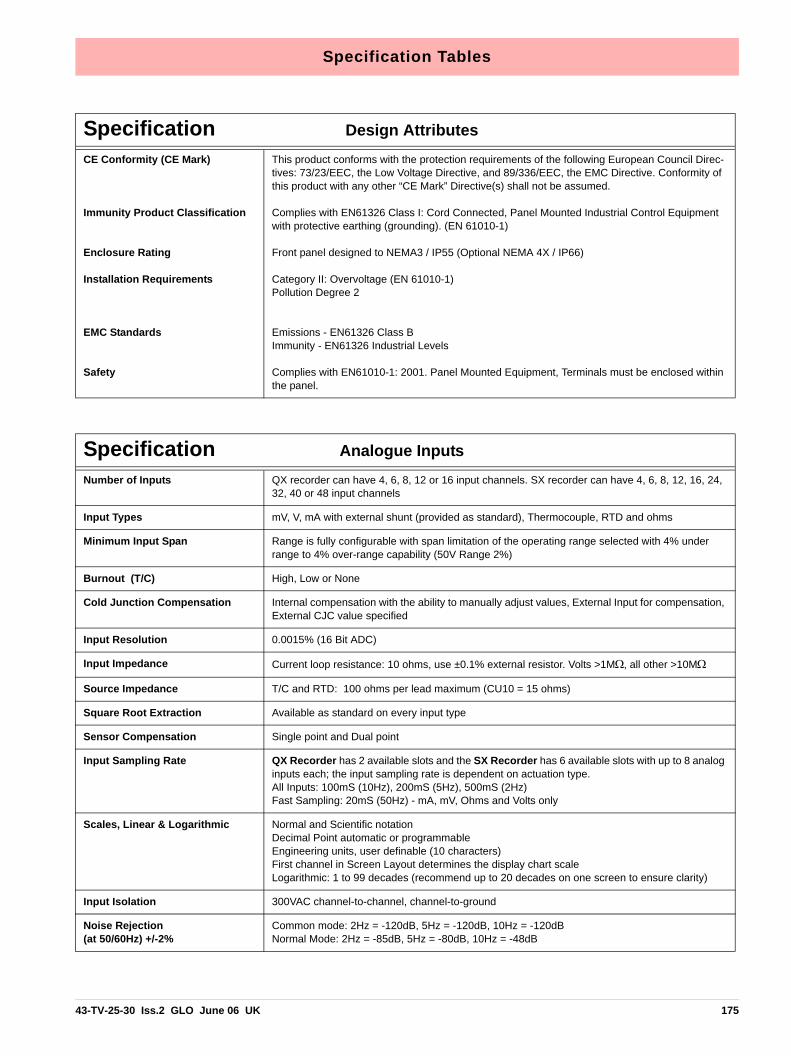
Specification Tables
CE Conformity (CE Mark)
Immunity Product Classification
Enclosure Rating
Installation Requirements
EMC Standards
Safety
This product conforms with the protection requirements of the following European Council Direc-tives: 73/23/EEC, the Low Voltage Directive, and 89/336/EEC, the EMC Directive. Conformity of this product with any other “CE Mark” Directive(s) shall not be assumed.
Complies with EN61326 Class I: Cord Connected, Panel Mounted Industrial Control Equipment with protective earthing (grounding). (EN 61010-1)
Front panel designed to NEMA3 / IP55 (Optional NEMA 4X / IP66)
Category II: Overvoltage (EN 61010-1)Pollution Degree 2
Emissions - EN61326 Class BImmunity - EN61326 Industrial Levels
Complies with EN61010-1: 2001. Panel Mounted Equipment, Terminals must be enclosed within the panel.
Specification Design Attributes
Specification Analogue InputsNumber of Inputs QX recorder can have 4, 6, 8, 12 or 16 input channels. SX recorder can have 4, 6, 8, 12, 16, 24,
32, 40 or 48 input channels
Input Types mV, V, mA with external shunt (provided as standard), Thermocouple, RTD and ohms
Minimum Input Span Range is fully configurable with span limitation of the operating range selected with 4% under range to 4% over-range capability (50V Range 2%)
Burnout (T/C) High, Low or None
Cold Junction Compensation Internal compensation with the ability to manually adjust values, External Input for compensation, External CJC value specified
Input Resolution 0.0015% (16 Bit ADC)
Input Impedance Current loop resistance: 10 ohms, use ±0.1% external resistor. Volts >1MΩ, all other >10MΩ
Source Impedance T/C and RTD: 100 ohms per lead maximum (CU10 = 15 ohms)
Square Root Extraction Available as standard on every input type
Sensor Compensation Single point and Dual point
Input Sampling Rate QX Recorder has 2 available slots and the SX Recorder has 6 available slots with up to 8 analog inputs each; the input sampling rate is dependent on actuation type.All Inputs: 100mS (10Hz), 200mS (5Hz), 500mS (2Hz)Fast Sampling: 20mS (50Hz) - mA, mV, Ohms and Volts only
Scales, Linear & Logarithmic Normal and Scientific notationDecimal Point automatic or programmableEngineering units, user definable (10 characters)First channel in Screen Layout determines the display chart scaleLogarithmic: 1 to 99 decades (recommend up to 20 decades on one screen to ensure clarity)
Input Isolation 300VAC channel-to-channel, channel-to-ground
Noise Rejection(at 50/60Hz) +/-2%
Common mode: 2Hz = -120dB, 5Hz = -120dB, 10Hz = -120dBNormal Mode: 2Hz = -85dB, 5Hz = -80dB, 10Hz = -48dB
43-TV-25-30 Iss.2 GLO June 06 UK 175
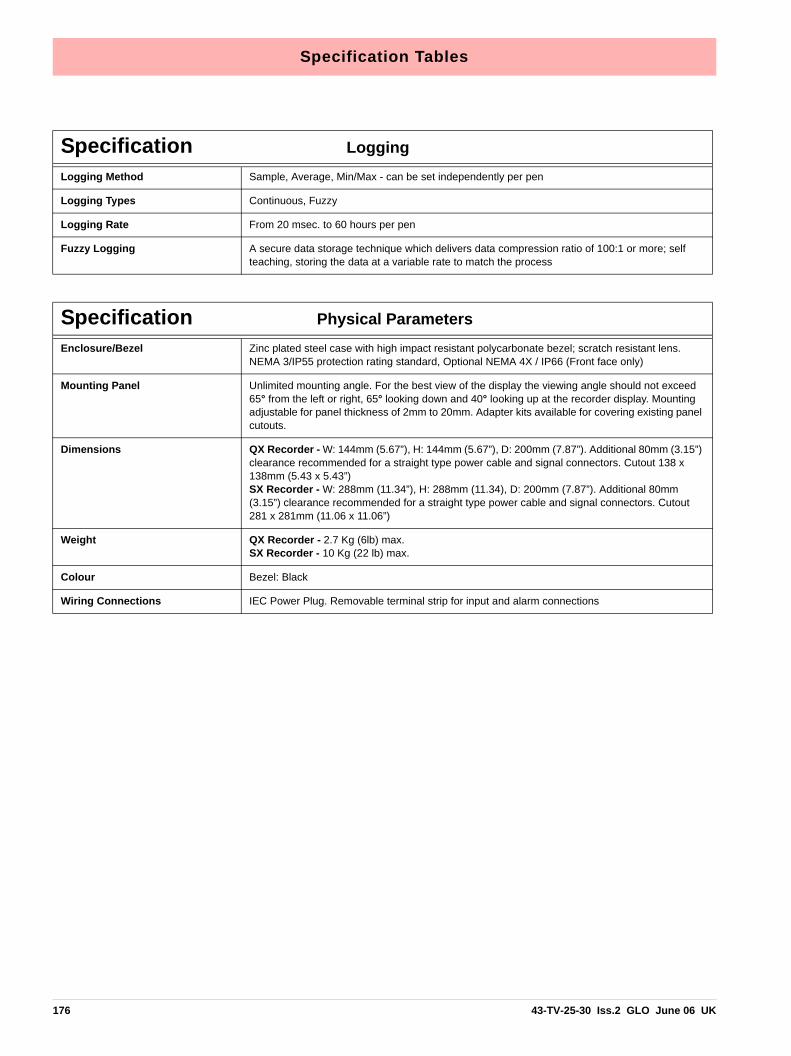
Specification Tables
Specification LoggingLogging Method Sample, Average, Min/Max - can be set independently per pen
Logging Types Continuous, Fuzzy
Logging Rate From 20 msec. to 60 hours per pen
Fuzzy Logging A secure data storage technique which delivers data compression ratio of 100:1 or more; self teaching, storing the data at a variable rate to match the process
Specification Physical ParametersEnclosure/Bezel Zinc plated steel case with high impact resistant polycarbonate bezel; scratch resistant lens.
NEMA 3/IP55 protection rating standard, Optional NEMA 4X / IP66 (Front face only)
Mounting Panel Unlimited mounting angle. For the best view of the display the viewing angle should not exceed 65° from the left or right, 65° looking down and 40° looking up at the recorder display. Mounting adjustable for panel thickness of 2mm to 20mm. Adapter kits available for covering existing panel cutouts.
Dimensions QX Recorder - W: 144mm (5.67”), H: 144mm (5.67”), D: 200mm (7.87”). Additional 80mm (3.15”) clearance recommended for a straight type power cable and signal connectors. Cutout 138 x 138mm (5.43 x 5.43”)SX Recorder - W: 288mm (11.34”), H: 288mm (11.34), D: 200mm (7.87”). Additional 80mm (3.15”) clearance recommended for a straight type power cable and signal connectors. Cutout 281 x 281mm (11.06 x 11.06”)
Weight QX Recorder - 2.7 Kg (6lb) max.SX Recorder - 10 Kg (22 lb) max.
Colour Bezel: Black
Wiring Connections IEC Power Plug. Removable terminal strip for input and alarm connections
176 43-TV-25-30 Iss.2 GLO June 06 UK

Specification Tables
Input Range Performance Accuracy Table
Input Actuation (Linear)
Range Accuracy Temp. Stability +/-
Input Impedance
Millivolts DC -5 to 5, -10 to 10, -25 to 25, -50 to 50, -100 to 100,
-250 to 250, -500 to 500, -1000 to 1000
+/- 0.2% F.S.+/- 0.1% F.S. +/- 0.1% F.S.
0.01%/ °C0.01%/ °C0.01%/ °C
>10M ohms>10M ohms>10M ohms
Volts DC -0.3 to 0.3, -0.6 to 0.6, -1.5 to 1.5, -3 to 3, -6 to 6, -12 to 12,
-25 to 25, -50 to 50
+/- 0.1% F.S. +/- 0.1% F.S. +/- 0.1% F.S.
0.01%/ °C0.01%/ °C0.01%/ °C
>1M ohms>1M ohms>1M ohms
Milliamps ** 4 to 20, 0 to 20 +/- 0.2% F.S. 0.01%/ °C
Ohms, 200 0 to 200 +/- 0.1% F.S. 0.01%/ °C
Ohms, 500 0 to 500 +/- 0.1% F.S. 0.01%/ °C
Ohms, 1000 0 to 1000 +/- 0.1% F.S. 0.01%/ °C
Ohms, 4000 0 to 4000 +/- 0.1% F.S. 0.01%/ °C
Input Actuation(Thermocouples)
Range Reference Accuracy Temp. Stability +/-
°F °C +/- °F +/- °C
B* 500 to 10001000 to 3300
260 to 538538 to 1816
8.14.0
4.52.2 0.01%/ °C
E* -454 to -328-328 to -94-94 to 1832
-270 to -200-200 to -70-70 to 1000
21.63.11.3
121.70.7
0.01%/ °C
J* -346 to 32 32 to 2192
-210 to 00 to 1200
3.11.2
1.70.7
0.01%/ °C
K* -454 to -94-94 to 2502
-270 to -70-70 to 1372
361.8
201
0.01%/ °C
R* -58 to 500500 to 1202
1202 to 3214
-50 to 260260 to 650
650 to 1768
6.72.72.0
3.71.51.1
0.01%/ °C
S* -58 to 500500 to 18321832 to 31103110 to 3214
-50 to 260260 to 1000
1000 to 17101710 to 1768
5.92.72.02.5
3.31.51.11.4
0.01%/ °C
T* -454 to -346-346 to 752
-270 to -210-210 to 400
9.71.8
5.41
0.01%/ °C
L* -328 to 3232 to 1652
-200 to 00 to 900
2.21.3
1.20.7
0.01%/ °C
G* (W_W26) 32 to 212212 to 600
600 to 15261526 to 27592759 to 4199
0 to 100100 to 316316 to 830
830 to 15151515 to 2315
4511.25.03.15.0
256.22.81.72.8
0.01%/ °C
C* (W5, W26) 32 to 356356 to 2228
2228 to 4199
0 to 180180 to 1220
1220 to 2315
4.53.66.7
2.52
3.7
0.01%/ °C
M* (NiMo-NiCo) (NNM90) -58 to 698698 to 2570
-50 to 370370 to 1410
2.01.4
1.10.8
0.01%/ °C
43-TV-25-30 Iss.2 GLO June 06 UK 177

Specification Tables
Reference Temperature: 22°C Reference Sample Rate: 2Hz (500msec)Reference Humidity: 65% RH +/-15% Long term stability: 0.2%/year* Does not includes reference junction calibration of ±1.0 º C using the standard “ice bath” method of calibration. Factory accuracy can be im-proved by performing a field calibration. Also does not include any error on the sensor.
** Tolerance for these input types includes that of the external shunt resistors (0.1% tolerance)
N* (Nicosil Nisil) -328 to 212212 to 2372
-200 to 100100 to 1300
5.82.0
3.21.1
0.01%/ °C
Chromel/Copel* -58 to 1112 -50 to 600 1.1 0.6 0.01%/ °C
P* (Platinel) 32 to 2534 0 to 1390 2.5 1.4 0.01%/ °C
D* 32 to 356356 to 3344
3344 to 4515
0 to 180180 to 1840
1840 to 2490
6.34
11.7
3.52.26.5
0.01%/ °C
PT100 α = 0.00385 -328 to 1562 -200 to 850 1.1 0.6 0.01%/ °C
PT200 -328 to 1562 -200 to 850 1.1 0.6 0.01%/ °C
PT500 -328 to 1562 -200 to 850 1.1 0.6 0.01%/ °C
PT1000 -328 to 1562 -200 to 850 1.1 0.6 0.01%/ °C
100 ohm Nickel -76 to 356 -60 to 180 0.9 0.5 0.01%/ °C
120 ohm Nickel -112 to 500 -80 to 260 0.5 0.3 0.01%/ °C
Cu10 -328 to 500 -200 to 260 0.7 0.4 0.01%/ °C
Cu53 32 to 302 0 to 150 0.5 0.3 0.01%/ °C
Input Actuation (Linear)
Range Accuracy Temp. Stability +/-
Input Impedance
Specification OptionsPulse Input (optional) 4 isolated inputs per board, frequency – 1Hz to 25kHz, updated once per sec.
Input: Low < 1V, High >4V to <50V or Volt free input: Low = short circuit, High = open circuit.
Alarm Outputs (optional) Programmable alarm set points (6 per pen) can be configured to activate up to 16 outputs for the QX Recorder and 48 outputs for the SX Recorder. Update rate: 200 ms for all alarms. Number/Type: • 4 or 8 relay contacts SPDT, 3A 240VAC, 3A 24VAC/DC, 0.2A 240VDC (non-inductive, inter-
nally suppressed) • 8 I/O or 16 I/O - SPNO 1A 24VDC (non-inductive, internally suppressed)Activation: Fully programmable internal alarm levels. Assignable to any relay or discrete output.
Digital Input/Output 8 I/O or 16 I/O: all channels may be selected freely as either digital inputs or outputs. The Digital I/O card also has 4 channels that can be set as pulse inputs (channels 1 to 4). The operat-ing frequency for pulse inputs on the Digital I/O card is 1kHz max.4 relay outputs: all four channels are relay outputs only.8 relays/ 2 DI card: two outputs can be configured for use as digital inputs: A digital input is provided by a volt free contact between the normally open (NO) and the common (C) terminals of an output relay. If the 2 Digital inputs are used only 6 relay outputs are available.
Custom Screens (optional) Provides the capability in the recorder to accept custom screen designs from the Screen Designer.
OPC Server (optional) OPC 3.0 DA compliant. Totalisers and up to 96 pens can be transmitted via OPC server, max poll rate 1/s.
178 43-TV-25-30 Iss.2 GLO June 06 UK
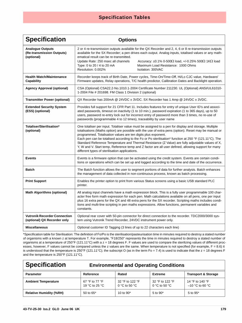
Specification Tables
*Specification table for Sterilisation: The definition of Fo/Po is the sterilisation/pasteurisation time in minutes required to destroy a stated number of organisms with a known z at temperature T. For example, "F18/250" represents the time in minutes required to destroy a stated number of organisms at a temperature of 250°F (121.11°C) with a z = 18 degrees F. F values are used to compare the sterilizing values of different proc-esses, however, F values cannot be compared unless the z values are the same. When temperature is not specified (for example, F = 8.6) it is understood that the temperature is 250°F (121.11°C); the subscript O (as in the term Fo = 7.4) is used to indicate that the z = 18 degrees F and the temperature is 250°F (121.11°C).
Analogue Outputs (Re-transmission Outputs)(optional)
2 or 4 re-transmission outputs available for the QX Recorder and 2, 4, 6 or 8 re-transmission outputs available for the SX Recorder; a pen drives each output. Analog inputs, totalised values or any math-ematical result can be re-transmitted.Update Rate: 250 msec all channels Accuracy: ±0.1% 0-500Ω load, +/-0.25% 500Ω 1KΩ loadType: 0 to 20 / 4 to 20 mA Maximum Load Resistance: 1000 OhmsResolution: 0.002% Isolation: 300VAC
Health Watch/Maintenance Capability
Recorder keeps track of Birth Date, Power cycles, Time-On/Time-Off, Hi/Lo CJC value, Hardware/Firmware updates, Relay operations, T/C health predictor, Calibration Dates and Backlight operation.
Agency Approval (optional) CSA (Optional) CSA22.2-No.1010.1-2004 Certificate Number 211230. UL (Optional) ANSI/UL61010-1-2004 File # 201698. FM Class 1 Division 2 (optional)
Transmitter Power (optional) QX Recorder has 200mA @ 24VDC ± 3VDC. SX Recorder has 1 Amp @ 24VDC ± 3VDC.
Extended Security System (ESS) (optional)
Provides full support for 21 CFR Part 11. Includes features for entry of unique User ID’s and associ-ated passwords, timeout on inactivity (1 to 10 min.), password expiration (1 to 365 days), up to 50 users, password re-entry lock out for incorrect entry of password more than 3 times, no re-use of passwords (programmable 4 to 12 times), traceability by user name
Totaliser/Sterilisation* (optional)
One totaliser per input. Totaliser value must be assigned to a pen for display and storage. Multiple totalisations (Maths option) are possible with the use of extra pens (option). Reset may be manual or programmed. Totalisation values are ten digits plus exponent.Each pen can be totalised according to the Fo or Po sterilisation* function at 250 °F (121.11°C). The Standard Reference Temperature and Thermal Resistance (Z Value) are fully adjustable values of X, Y, W and V. Start temp, Reference temp and Z factor are all user defined, allowing support for many different types of sterilisation applications.
Events Events is a firmware option that can be activated using the credit system. Events are certain condi-tions or operations which can be set up and logged according to the time and date of the occurrence.
Batch The Batch function allows the user to segment portions of data for further analysis. Batch enhances the management of data collected in non-continuous process, known as batch processing.
Print Support Enables the printer option to print from various Status screens using a basic USB standard PLC printer.
Math Algorithms (optional) All analog input channels have a math expression block. This is a fully user programmable 100 char-acter free form math expression for each pen. Math calculations available on all pens, one per input plus 16 extra pens for the QX and 48 extra pens for the SX recorder. Scripting maths includes condi-tions and multi-line scripting in pen maths expressions. Allow functions, permanent variables and constants.
Vutronik Recorder Connection (optional) QX Recorder only
Optional rear cover with 50-pin connector for direct connection to the recorder. TDC2000/3000 sys-tem using Vutronik Trend Recorder, 24VDC instrument power only.
Miscellaneous Optional customer ID Tagging (3 lines of up to 22 characters each line)
Specification Environmental and Operating ConditionsParameter Reference Rated Extreme Transport & Storage
Ambient Temperature 67 °F to 77 °F19 °C to 25 °C
32 °F to 122 °F0 °C to 50 °C
32 °F to 122 °F0 °C to 50 °C
14 °F to 140 °F –10 °C to 60 °C
Relative Humidity (%RH) 50 to 65* 10 to 90* 5 to 90* 5 to 95*
Specification Options
43-TV-25-30 Iss.2 GLO June 06 UK 179

Specification Tables
* The maximum rating only applies up to 104°F (40°C). For higher temperatures, the RH spec is de-rated to maintain constant moisture content
LED Flash CodesLEDs are fitted on the Analogue Input card, Analogue Output card, Pulse Input card, 4 and8 Alarm Relay cards and the 8 and 16 Digital IO cards. The LEDs can be seen through sixholes on the left side of the QX recorder, and 18 holes on the SX recorder (looking from thefront).
Red LED flash codes relate to the first fault stored in the error buffer. With no faults, the redLED remains off.
When the red LED is flashing, the green LED stays lit. The green LED flashes for normaloperation. The board outputs the flash code for about 30 seconds after it was registered.
Vibration Frequency (Hz) Acceleration (g)
00
0 to 700.1
0 to 1000.2
0 to 1000.5
Mechanical Shock Acceleration (g) Duration (ms)
00
130
530
2030
Mounting Position from Vertical Tilted Forward Tilted Backward Tilted to Side (+/-)
5°5°5°
40°65°65°
40°65°65°
AnyAnyAny
Power Requirements Mains Voltage (Vrms) Low Voltage AC (Vrms) DC Voltages Frequency (Hz)
220 to 24024 +/- 224 +/- 249.8 to 50.2
100 to 25020 to 3020 to 5047 to 63
90 to 26420 to 3020 to 5047 to 63
N/AN/AN/AN/A
Power Consumption QX: AC: <40W (max), DC: <40W (max) Typical 20W. SX: AC: <60W (max), DC: <60W (max) Typical 30W
Warm Up 30 minutes minimum
Seismic Qualification Complies with IEEE 323-1974 and/or 1983 and IEEE 344-1975 and/or 1987 (option). Hardware includes an IEC bracket.
Specification Environmental and Operating Conditions
Table 12.3 :
Red LED Flash codes: Sequence: Type of Fault:
1,1 flash once, pause, flash once, pause etc Hardware
2,2 flash twice, pause, flash twice, pause etc Communications
3,3 flash three times, pause, flash three times, pause etc Memory
4,4 flash four times, pause, flash four times, pause etc Other
1,2 flash once, pause, flash twice more quickly, pause, flash once etc (added as CJC could be unplugged…)
CJC fault
1,3 If another error is also present with CJC error, flash once, pause, flash 3 times
CJC fault +
180 43-TV-25-30 Iss.2 GLO June 06 UK

Appendix A: Quality and Safety
CE MarkHoneywell X Series recorders are compliant with Low Voltage Directive 73/23/EEC asamended by 93/68/EEC, and the Electromagnetic Capability Directive 89/336/EEC asamended by 92/31/EEC and 93/68/EEC.
SafetyThe product range of instruments is compliant with the requirements of BS EN 61010-1:2001 “Safety Requirements for Electrical Equipment for Measurement, Control and labo-ratory Use” and UL 61010C-1 and CSA 22.2-1010.1. If the equipment is used in a mannernot specified, the protection provided by the equipment may be impaired.
43-TV-25-30 Iss.2 GLO June 06 UK 181

Safety
182 43-TV-25-30 Iss.2 GLO June 06 UK
Appendix B: Maths Expressions
Full Maths & Script ProcessingThe X Series recorders are supplied with Basic Maths functions: Add, Subtract, Divideand Multiply. There are two further options that can be added, Full Maths and anextremely powerful Scripting processing module. Scripting delivers an additional level ofenhanced capabilities with multi line script processing. Full and Scripting Maths must beactivated in the recorder as a Firmware credit option.
When a recorder setup is loaded into the TrendManager software the Maths capabilitieswill be transferred with the setup. If you are creating a new recorder in TrendManagersoftware to be transferred to a recorder the Maths capabilities will be available but will onlybecome active if the recorder has the same Maths functions enabled.
This document provides the Maths Variable and Function table and examples of the capa-bilities from the simple to the complex to assist the user in understanding the concepts andpotential of these features.
*** Important Note, Full Maths and Script functions are Options and must be enable usingthe Credit System. Be sure to enable these options or they will not be available. See “Firm-ware Credit System” on page 129.
Notes:
• if, elseif & else are followed by expressions in “curly brackets” {….}
• lines within the curly brackets always end in semicolon e.g. ;
• every expression within curly brackets “{…}” must include a “return”
• Small values (fractions) entered into a maths expression will require a zero before the deci-mal point. Eg. 0.5
• Outputs that are set to Single Pulse should not be used as a part of a maths expression as it can cause spurious values.
• No white spaces
• Syntax is not case sensitive
All of the following tables display functions available in Full and Scripting Maths unlessotherwise stated.
NOTICEFull Maths and Scripting functions are Options and must be enable using the CreditSystem. Be sure to enable these options in the recorder or they will not be available.See “Firmware Credit System” on page 129.
43-TV-25-30 Iss.2 GLO June 06 UK 183

Full Maths & Script Processing
Maths Variable and Function TablesTable 14.1 : Maths Variable Table
Maths Variables Syntax Description
Analogue Input (Eng values) An Get the value of Analogue n (1 to 48) in Engi-neering units
Analogue Raw (Electrical values)
RAn Get the value of Raw Analogue n (1 to 48) in Electrical values
Pen Pn Get the value of Pen n (1 to 96)
Digitals Dn Get the value of Digital Input n (1 to 48)
Digital Input bit pattern DIOn Get the 16 bit pattern from the DIO slots, where n= 1,2 or 3 (Slot G, H & I respectively). Returned as a 16 bit word (0 to 65535). A channel configured as an output is set to 0.
RT Compensation RTCOMPn Get RT Compensation value for channel n (1 to 48) Units mV
RT Calibration RTCALn Get RT Calibration value for channel n (1 to 48). Units mA
CJC CJCn Get the Board CJC value. N = 1 to 6 (Returns value in Degrees F, C or K depending on the localisation setting
CJC in Degrees C CJCnC Get the Board CJC value. N = 1 to 6 (Always returns value in degrees C)
Pulse Inputs (AI slots) HPULn Get the Pulse frequency from the Pulse card n = 1 to 48 (25kHz max)
Pulse Inputs (DIO Slots) LPULn Get the Pulse frequency from the Digital Input card when in Pulse mode n = 1 to 48 (1kHz Max)
Pen Minimum Value PnMINU Gets the Pen Minimum value n = 1 to 96
Pen Maximum Value PnMAXU Gets the Pen Maximum value n = 1 to 96
Alarm Level PnAxL Gets the Alarm Level, n is Pen number 1 to 96 and x is alarm number 1 to 6
Totaliser Tn Get Totaliser value n = 1 to 96
Comms Variables CVn Get the Comms variable n = 1 to 96
Blkv BLKVx Get the local variable x. This variable is local to this script. There is a maximum of 20 local var-iables per script.
Glbv GLBVx Get the global variable x. This is a global varia-ble accessible to all scripts. There is a maxi-mum of 200 global variables.
184 43-TV-25-30 Iss.2 GLO June 06 UK

Full Maths & Script Processing
Pstv PSTVx Get the persisted Global variable x. Persisted global variables maintain their value through a power cycle. There is a maximum of 50 per-sisted global variables.
Compact Flash free storage space
CFFREE Returns the percentage of free storage space available on the Compact Flash card
USB1 free storage space USB1FREE Returns the percentage of free storage space available on the USB storage key fitted initially (front or rear).
USB2 free storage space USB1FREE Returns the percentage of free storage space available on the USB storage key fitted after the first USB has been fitted (front or rear).
Batch Mode BATMD Returns 1= batch running, 2 = batch stopped or 3 = batch paused
Internal memory hours left INTHRS Returns the amount of hours left until the inter-nal memory starts to recycle (over-write).
Table 14.2 : Maths Function Table
Maths Functions Syntax Description
Add + Returns the result of the addition
Subtract - Returns the result of the subtraction
Multiply * Returns the result of the multiplication
Divide / Returns the result of the division
Sin* sin[x] Returns the SIN of x
Cos* cos[x] Returns the COSINE of x
Tan* tan[x] Returns the TANGENT of x
SinH* sinh[x] Returns the Hyperbolic SIN of x
CosH* cosh[x] Returns the Hyperbolic COSINE of x
TanH* tanh[x] Returns the Hyperbolic TANGENT of x
ASin* asin[x] Returns the Arc SIN of x
ACos* acos[x] Returns the Arc COS of x
ATan* atan[x] Returns the Arc TAN of x
Ceiling ceil[x] Round up x to the nearest whole number
Floor floor[x] Round down x to the nearest whole number
Round round[x] Rounds x to the nearest whole number
Table 14.1 : Maths Variable Table
Maths Variables Syntax Description
43-TV-25-30 Iss.2 GLO June 06 UK 185

Full Maths & Script Processing
* Functions use radians (2π radians = 360 degrees)
Damping examples:Example 1: if P1 was measuring degrees C the expression P1 = damp[A1, P1, 3] will damp the signal with changes up to 3 degrees C, any change over 3 degrees between readings will be damped but by a small amount. Example 2: P5 = damp[A2, P5, A3] will damp the A2 input up to a level determined by input A3, note the reference parameter (P5) is always the same as the pen it is being used in, this should always be the case.
Floating point Absolute fabs[x] Returns the Floating Point Absolute value of x
Exponent exp[x] Returns the Exponential of x
Log log[x] Returns the Base 10 Log of x
Ln ln[x] Returns the Natural Log of x
Square Root sqrt[x] Returns the Square Root of x
Power pow[x,y] Returns the value of x raised to the power y. Can also be represented by ^
Power x^y Returns the value of x raised to the power y.
Modulus x%y Returns the value of x with a modulus of y
Square sq[x] Returns the square of x (i.e. x multiply by x)
Reciprocal recip[x] Returns the reciprocal of x (i.e. 1/x)
Root root[x,y] Returns the y root of x
Eval eval[x] Returns 1 if x is non zero, otherwise returns zero
Damp damp[x,y,z] x = input, y = Pn (pen variable being used) and z = damping limit in engineering units. See “Damping examples:” on page 186.
Table 14.3 :
Compare & Convert Syntax Description
F2c f2c[x] Converts a temperature in F to one in C
C2f c2f[x] Converts a temperature in C to one in F
%RHc rhc[x,y] Returns % Relative Humidity with y as the dry bulb temperature in degrees C, and x the wet bulb tem-perature in degrees C
%RHf rhf[x,y] Returns % Relative Humidity with y as the dry bulb temperature in degrees F, and x the wet bulb tem-perature in degrees F
Hi hi[x,y] Returns the larger value of x & y
Table 14.2 : Maths Function Table
Maths Functions Syntax Description
186 43-TV-25-30 Iss.2 GLO June 06 UK

Full Maths & Script Processing
Timers must return a value, so assign to a variable. e.g.BLKV1 = tpause[1]. Value returned is the same as tget[1].
Lo lo[x,y] Returns the lower value of x & y
Hi4 hi4[x,y,x1,y1] Returns the larger value of x, y, x1,y1
Lo4 lo4[x,y,x1,y1] Returns the lower value of x, y, x1, y1
Over over[x,y] Returns x if it’s larger than y, otherwise returns 0
Under under[x,y] Returns x if it’s less than y, otherwise returns 0.
Inside inside[x,y,z] Returns x if between y & z, otherwise returns 0.
Outside outside[x,y,z] Returns x if outside of y & z, otherwise returns 0
Table 14.4 :
Timers Syntax Description
Trun trun[x,y] Starts the timer x in y mode. (Mode 1 = reset to 0 and run, Mode 0 = resume from previous value)
Tget tget[x] Returns the elapsed time of timer x since start
Tpause tpause[x] Pauses the timer x
Treset treset[x] Resets the timer x
Table 14.5 :
Accessors Syntax Description
Glbv Glbv[x] Get the value of global variable number x
Locv Locv[x] Get the value of local variable number x
Pen Pen[x] Get the value of Pen number x
Ai Ai[x] Get the value of Analogue Input number x
Di Di[x] Get the state of Digital input number x
Tot TOT[x] Get the current value of totaliser x
Alamct Almct[x,y] Get the current alarm count for Pen x, Alarm y (the alarm number as identified in alarm mes-sages)
Alamst Almst[x,y] Get the current alarm state for Pen x, Alarm y (I = active 0 = inactive)
Table 14.3 :
Compare & Convert Syntax Description
43-TV-25-30 Iss.2 GLO June 06 UK 187

Full Maths & Script Processing
Table 14.6 :
Boolean Operators Syntax Description
Assign = Assigns one variable to another. e.g.GLBV1=A1. (GLBV1 becomes the value of A1).
Equal to == Returns a true or false result from testing if two variables are equal to each other. e.g. IF (A1==GLBV1)
Not equal to != Returns a true or false result from testing if two variables are not equal to each other. e.g. IF (A1!=GLBV1)
AND && Returns a true or false result from testing if two tests are both true. e.g. IF (A1==GLBV1) && (A2!=GLBV2)
OR || Returns a true or false result from testing if one or other or both tests are true. e.g. IF (A1==GLBV1) || (A2!=GLBV2)
XOR ~ Returns a true or false result from testing if one or other (but not both) tests are true. e.g. IF (A1==GLBV1) ~ (A2!=GLBV2)
NOT ! Returns true if the result is 0, otherwise returns false.
Greater than > Returns a true or false result from testing if one variable is greater than another
Greater than or equal to >= Returns a true or false result from testing if one variable is greater or equal to than another
Less than < Returns a true or false result from testing if one variable is less than another
Less than and equal to <= Returns a true or false result from testing if one variable is less than or equal to another
188 43-TV-25-30 Iss.2 GLO June 06 UK
Full Maths & Script Processing
Table 14.7 :
Functions for Scripts Syntax Description
If if(x) Carries out a conditional test and if true steps into brackets to run. If false, steps to next test without operating the contents of the brackets. Next step will be either elseif or else.Must always finish with a return.If (x>5){return y;}
Else else Steps into brackets to run. Must always finish with a return.else{return y;}
Elseif elseif(x) Carries out a conditional test and if true steps into brackets to run. Must always finish with a return.elseif (x>4){return y;}
First run (FIRSTRUN) Returns true if the script is being run for the first time, otherwise returns false
Set Changed (SETUP-CHANGED)
Returns true if the setup has been changed, otherwise returns false
Time Changed (TIMECHANGED)
Returns true if the time has been changed, oth-erwise returns false
43-TV-25-30 Iss.2 GLO June 06 UK 189

Full Maths & Script Processing
Full MathsFull Maths functions provides a simple and intuitive method for the user to carry out numer-ous mathematical functions. Some examples are shown below
Table 14.8 : Full Maths examples
Full Maths examples
P4=lo[A1,A2] Pen 4 shows the result of the lowest of either A1 or A2
P3=(A1+A2)*SQRT[A3] Pen 3 shows the result of Analogue input 1 added to Analogue input 2, all multiplied by the square root of Analogue input 3
P4=GLBV1 P4 shows the Global Variable 1
NOTICEPlease note “Pn=” is not entered in the Maths Block and is assumed by the Recordere.g. To enter the equation P2=A2, the user would just type A2
190 43-TV-25-30 Iss.2 GLO June 06 UK

Full Maths & Script Processing
Script Function Application ExamplesTo enter a script for a Pen, ensure that “Maths Type” in the Pen Menu is set to Scripting.
Example 14 flow meters are fed into the recorder to trend, totalise and record daily flow. The applicationrequires that the user must know and record which flow meter is outputting the highest flowat any particular time. This can of course be derived from the four lots of recorded data, butnot only is this extra analysis later, but a real time display is required.
The application is easily solved by using the Script Function in the recorder, represented inpseudo code the script is as follows:
If input 1 is bigger than all the others, then make the global variable (1) equal to channel 1,and display and record input 1.
If input 2 is bigger than all the others, then make the global variable (1) equal to channel 2,and display and record input 2.
If input 3 is bigger than all the others, then make the global variable (1) equal to channel 3,and display and record input 3.
If none of the above are correct then Input 4 must be the highest, so make the global variable(1) equal to channel 4, and display and record input 4.
Display the global variable (1) on another pen to show which channel is biggest at any giventime.
Pen 5 is chosen to record the highest channel input, and channel 6 is chosen to record whichinput is the highest.
The greater than “>” is used, the AND “&&” Boolean is also used, and the global variableGLBV1 is used to hold the current highest channel number.
Converting this to an actual script gives the following:
If ((A1>A2)&&(A1>A3)&&(A1>A4)) This tests if flow meter 1 is more than 2, 3 and 4
{
GLBV1=1; If yes, then set display indicator to meter 1
return A1; And return the current flow reading
}
elseif ((A2>A1)&&(A2>A3)&&(A2>A4)) This tests if flow meter 2 is more than 1, 3 and 4
{
GLBV1=2; If yes, then set display indicator to meter 2
return A2; And return the current flow reading
}
elseif ((A3>A1)&&(A3>A2)&&(A3>A4)) This tests if flow meter 3 is more than 1, 2 and 4
{
GLBV1=3; If yes, then set display indicator to meter 3
43-TV-25-30 Iss.2 GLO June 06 UK 191

Full Maths & Script Processing
In this application, the flow meters are connected to inputs 1, 2, 3 and 4 at the rear of therecorder, and these are recorded on Pens 1 to 4
P1=A1
P2=A2
P3=A3
P4=A4
Pen 5 has the script above, which records and displays the highest flow rate of the four.
Pen 6 is set to record and display the input (between 1 and 4) that is the highest rate
P6=GLBV1
Example 2In the same application as above, the user has noticed that whilst flow meter 2 normally hasthe highest flow rate, on occasion a surge in flow meter 3 causes problems down stream.The user needs to monitor the two inputs and count the number of times flow meter 3 read-ing exceeds that of flow meter 2.
The code consists of the two flow meter readings, and a change counter that totals thenumber of times that flow 3 exceeds that of flow 2.
The pseudo code is written as:
If flow meter 3 has a larger reading than flow meter 2, check to ensure that it was alreadygreater than meter 2, if it was return the latest change count value.
If it was not greater than meter 3 last time, set a flag to indicate a change and increment thechange counter by 1, then return the latest change counter.
If flow meter 3 is less than 2, simply return the change count value with no increment.
Pen 7 is used to implement this script and is implemented as follows
return A3; And return the current flow reading
}
else If none of the above are true, then 4 is biggest
{
GLBV1=4; So set display indicator to meter 4
return A4; And return the current flow reading
}
NOTICEPlease note “Pn=” is not entered in the Maths Block and is assumed by the Recordere.g. To enter the equation P2=A2, the user would just type A2
192 43-TV-25-30 Iss.2 GLO June 06 UK

Full Maths & Script Processing
With script above, BLKV (all Variables) are used to maintain values. It should be noted thatBLKV’s do not persist over a power removal, and if the application were to require a non-volatile count, then BLKVn should be substituted with PSTVn.
Example 3The application described in Examples 2 and 3 is to be extended to totalise the amount oftime that Input 1 is the highest of 1, 2, 3 & 4.
Again scripting can be used to easily solve this requirement.
The Pseudo code is written as
If input 1 is indicated as the current highest value, then display the timer.
If input 1 is not the highest input value, then stop totalising time and return the current timervalue.
We know that in Example 1, the highest value channel number is contained with GLBV1,and as this is a global variable it is also accessible from this script.
if (A3>A2) Tests if A3 is bigger than A2
{
if(BLKV1==1) If it was then tests if A3 was bigger than A2 last time period
{
return BLKV2; If it was return with the current change counter
}
else If not then
{
BLKV1=1; Set flag to show that A3 has just exceeded A2
BLKV2=BLKV2+1; Increment the change counter by 1
Return BLKV2; Return the new change counter total
} }
else If A3 is not bigger than A2
{
BLKV1=0; Set flag to show A2 is bigger than A3 this time
Return BLKV2; Return current change counter
}
if (GLBV1==1) Tests if the global variable 1 is equal to channel 1
{
43-TV-25-30 Iss.2 GLO June 06 UK 193

Full Maths & Script Processing
Note in this script above there is no way to reset the timer, this could be modified to allowthe user to reset this timer from a switch fed into a digital input as follows:
BLKV1=trun[1,0]; If it is then keep the timer running without resetting
return tget[1]; Return the current timer value
}
else If not then
{
BLKV1=tpause[1]; Pause the timer
return tget[1]; Return the current (paused) timer value
}
if(D1!=1) Tests if the DI 1 is not set
{ If it isn’t then
if (GLBV1==1) Tests if the global variable 1 is equal to channel 1
{
BLKV1=trun[1,0]; If it is then keep the timer running without resetting
return tget[1]; Return the current timer value
}
else
{ If not then
BLKV1=tpause[1];
return tget[1]; Pause the timer
} Return the current (paused) timer value
}
else If it is
{
BLKV1=treset[1]; reset the timer 1 to zero
return tget[1]; return the current (zeroed) timer value
}
194 43-TV-25-30 Iss.2 GLO June 06 UK

Full Maths & Script Processing
Example 4
Commenting in ScriptsThis is an example of how commenting can be used in scripts.you can use the standard C++ commenting, inline comments use \\ for example if ( A1 > 10 ){ return 9; // If A1 greater then 10 return 9} or for block (single or multiline commenting the /* to open and /* to close, these are C style comments and work as follows if ( A1 > 10 ){ return 9; /* If A1 greater then 10 return 9 */} for single line or if( A1 > 10 ){ /* if A1 is greater then 10 then return 9 which is completely useless but goes to show a multiline comment for pascal */ return 9;} these are also useful for commenting out code to try different things, for example if( A1 > 10 ){ return 9;}/*else{ return 20;}*/return A1; Here the else statement is "commented out" so it won't be included but can easily be re-in-troduced if required.
Maths Error MessagesWhen the Maths functionality is processing through the scrips you have written it will carryout Syntax and other checks. When it comes across operations, functions, brackets, etc.not expected or permitted it will report an error. However, the fault being reported may beon a previous line caused by the missing or incorrect function.
43-TV-25-30 Iss.2 GLO June 06 UK 195

Full Maths & Script Processing
196 43-TV-25-30 Iss.2 GLO June 06 UK

Appendix C: Thermocouple Connections
How Thermocouples workThermocouples produce a voltage dependant upon the temperature gradient between thehot and cold junctions. The hot junction is the measuring junction of the thermocouple, thecold junction is the point where the thermocouple wires are connected, usually the connec-tion block on the back of the recorder.
If the hot (measuring) junction is at 100°C and the connection block of the recorder is at 20°Cthe thermocouple will produce a voltage corresponding to 80°C, the difference between thehot and cold junctions.
For the recorder to correctly report the 100°C it needs to know the temperature at the coldjunction. There are 4 options of cold junction compensation (CJC) on the recorder that aredetailed below. The simplest and most common is to use the “Internal Automatic” compen-sation. This uses a CJC sensor built onto the AI board to measure the connector tempera-ture. In this case it will measure 20°C, this will then be added to the 80°C measured by thethermocouple to give a displayed reading of 100°C.
The 4 methods of cold junction compensation are described below.
All diagrams show passive burnout, for active burnout replace the + for *.
_
+
CJCColdJunction
20°C
100°C
Hot Junction
43-TV-25-30 Iss.2 GLO June 06 UK 197

Thermocouple CJC Compensation
Thermocouple CJC CompensationThe different methods for connecting thermocouples according to the type of reference areshown below.
Internal Automatic
Internal Auto. This is connected to the input terminals of the recorder, and the temperatureat this junction is being measured by a temperature sensor on the rear panel of the recorder.The reading from this sensor is read off against a value taken from the thermocouple table,which corresponds to the type of thermocouple being used. The corresponding reading involts for the temperature measured by the sensor is then used as a reference for the readingfrom the thermocouple.
Diagram shows passive burnout, for active burnout replace the + for *.
Temperature reading to maths expression
Readingin °C
(Volts)
C
DV
CJC Readingin volts
-
+
Thermocouplecable
Measuringjunction
Input terminals on rear panel of recorder
A
Inputsadded(C+D)
Look-up table (converts voltage read-ing to tem-perature)
ThermocoupleTable
198 43-TV-25-30 Iss.2 GLO June 06 UK

Thermocouple CJC Compensation
Ext 0°C Reference
Ext 0°C Reference. By keeping the reference junction at 0 °C then the negative input is act-ing as a 0 Volt reference so the voltage reading from the thermocouple can be passed di-rectly to the tables where the corresponding temperature reading can be found.
Diagram shows passive burnout, for active burnout replace the + for *.
External with a Specified Temperature
External Reference with a specified temperature. The reference junction is kept at a con-stant known temperature other than 0°C. This temperature can be specified in the setupmenus. This reference temperature is then used in the same way as the reading from thetemperature sensor using the Internal Reference method.
Diagram shows passive burnout, for active burnout replace the + for *.
Temperature reading to maths expression
V-
+
(Volts)
Reference junction held at 0 °C
0 Volts0 °C
Measuringjunction
Thermocouplecable
Copper wire
Input terminals on rear panel of recorder
Look-up table (converts volt-age reading to temperature)
Temperature reading to maths expression
(Volts)
C
DV
Reading in volts
-
+
Reference junction held at 45 °C
0 Volts45°C
Measuringjunction
Thermocouplecable
Copper wire
Inputterminals on rear panel of recorder
Inputsadded(C+D)
Look-up table (converts voltage read-ing to tem-perature)
Reftemp
Thermocouple Table
43-TV-25-30 Iss.2 GLO June 06 UK 199

Thermocouple CJC Compensation
External Input Reference
External Input Reference. The reference temperature reading in this method is providedby a separate temperature measuring device connected to another input, usually RT. Thisinput is processed in the normal way and then passed back into the thermocouple signalprocessing system as a temperature reading.
Reading in Volts
Temperaturereading to mathsexpression
A
C
_
+*
Inputterminals on rear panel of recorder
Copper wire
Normalsignalprocessing
ThermocoupleTable (convert R/Ttemp to Volts
(Volts)D
V
_
+
PT100
Copperwire
Thermocouplecable
Inputsadded(C+D)
Look-up table (converts voltage read-ing to tem-perature)
200 43-TV-25-30 Iss.2 GLO June 06 UK
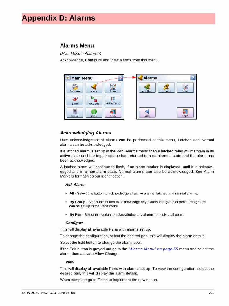
Appendix D: Alarms
Alarms Menu(Main Menu > Alarms >)
Acknowledge, Configure and View alarms from this menu.
Acknowledging AlarmsUser acknowledgment of alarms can be performed at this menu, Latched and Normalalarms can be acknowledged.
If a latched alarm is set up in the Pen, Alarms menu then a latched relay will maintain in itsactive state until the trigger source has returned to a no alarmed state and the alarm hasbeen acknowledged.
A latched alarm will continue to flash, if an alarm marker is displayed, until it is acknowl-edged and in a non-alarm state. Normal alarms can also be acknowledged. See AlarmMarkers for flash colour identification.
Ack Alarm
• All - Select this button to acknowledge all active alarms, latched and normal alarms.
• By Group - Select this button to acknowledge any alarms in a group of pens. Pen groups can be set up in the Pens menu
• By Pen - Select this option to acknowledge any alarms for individual pens.
ConfigureThis will display all available Pens with alarms set up.
To change the configuration, select the desired pen, this will display the alarm details.
Select the Edit button to change the alarm level.
If the Edit button is greyed-out go to the “Alarms Menu” on page 55 menu and select thealarm, then activate Allow Change.
ViewThis will display all available Pens with alarms set up. To view the configuration, select thedesired pen, this will display the alarm details.
When complete go to Finish to implement the new set up.
43-TV-25-30 Iss.2 GLO June 06 UK 201

202 43-TV-25-30 Iss.2 GLO June 06 UK

Appendix E: Ethernet
EthernetEthernet is a local area network (LAN) technology that transmits information between com-puters and other devices, at speeds of 10 or 100 million bits per second (Mbps). Each Ether-net equipped device operates independently of all other devices on the network. All devices attached to an Ethernet network are connected to a shared signalling system.Ethernet signals are transmitted serially, one bit at a time, over the shared signal channelattached to each device.
It is up to the high-level protocol that is sending data over the network to make sure that thedata is correctly received at the destination device.
Devices attached to an Ethernet network can send application data to one another usinghigh-level protocol software, such as TCP/IP protocol suite.
High-level protocols have their own system addresses, such as the 32-bit addresses usedin the current version of IP. The high-level IP-based networking software in a device is awareof its own 32-bit IP address and can read the 48-bit Ethernet address of its own network in-terface, but it doesn’t know the Ethernet addresses of the other devices on the network.
To discover the Ethernet addresses of other IP-based devices on the network another high-level protocol is used. For TCP/IP, this is done using a protocol called Address ResolutionProtocol (ARP).
Example:
Device X has an IP address of 195.23.37.1 and sends data over the Ethernet channel toanother IP-based device, Device Y with IP address 195.23.37.2. Device X sends the pack-ets of information containing an ARP request. The ARP request is asking the device with theIP address of 195.23.37.2 to identify the address of the Ethernet Interface.
Only Device Y with the IP address of 195.23.37.2 will respond, sending a packet with theEthernet address of device Y back to device X. Now device X and Y have each others Ether-net addresses to which data can be sent.
43-TV-25-30 Iss.2 GLO June 06 UK 203

204 43-TV-25-30 Iss.2 GLO June 06 UK

Appendix F: Fuzzy Logging
What is Fuzzy Logging?Fuzzy Logging is a real time Data Compression technique. Patent no. US 6,405,155 B2,developed at Honeywell as an alternative to the more standard methods of recording data.
Paperless Recorders are primarily used for exception recording. They spend most of theirlife trending and recording straight lines. Fuzzy Logging has been developed to improve theefficiency of data storage, and is particularly effective in exception recording exampleswhere normal operation consists of generally static inputs.
Fuzzy Logging looks for straight lines in the data stream, in real time, whether they are hor-izontal, climbing or descending. A straight line made up of say 10 points can be equally wellrepresented by 2 points, one at either end, the other 8 points are redundant. Fuzzy loggingworks by creating straight lines in the data and discarding redundant points.
What’s it for? …… To help the user in the trade off betweenScan Rate, Disk capacity and RecordingTime, after all the ‘Pie’ is only so big.
Fuzzy Logging has been developed to helpmaximise all three sections, in effect increas-ing the size of the ‘Pie’.
The result is a technique that delivers a hostof real world benefits over the more traditionalrecording methods.
1. Disks take longer to fill – changed less frequently, less site visits.
2. Faster scan rates can be used for any given disk size – giving greater resolution on the process.
3. Recording time can be extended.
4. Less hard disk memory required for archiving on the PC.
5. Quicker graphing of data.
6. Smaller data files for remote collection.
How does it work?Fuzzy Logging does not log data points that form part of a straight line.
The technique is best illustrated by the diagram below:
The Recording 'Pie'.
Scan Rate Storage CapacityRecording Period
43-TV-25-30 Iss.2 GLO June 06 UK 205

Diagram 1
Points marked: are NOT logged, as they lie on an ‘imaginary’ straight line between pointsmarked:
The graph of the Fuzzy Logged data, looks identical to the graph of the sampled data, buthas taken less than half the points to build it.
What about ‘Spikes’ on my trend line? Won’t it miss them?NO, you will not miss any ‘Spikes’, ‘Glitches’ or ‘Transients’ – these are what you need tosee!
As Fuzzy Logging is an adaptive technique, it will log as fast as it needs to in order to captureeverything.
Although not all points are logged, the base ‘Scan Rate’ of the input is the same as if youwere using a standard logging technique.
7654321
7654321
7654321
Time
Input Signal
Continuously Sampled data:
Fuzzy Logged data: 12 points only!
Changing ‘slope’ requires more data points to be logged, to capture the shape correctly.
206 43-TV-25-30 Iss.2 GLO June 06 UK

What about slowly drifting inputs?Again – No Problem. The algorithm is processed in ‘Real Time’, i.e. as the reading is taken.As it already knows the previous logged readings it can calculate where the next pointshould be (assuming it’s on a straight line) – if the measured value does not equal the pre-dicted value, the point is logged as it no longer forms part of the straight line.
Fuzzy Logging, looks for straight lines – at any angle. Not just on the horizontal.
Do you have any examples?Example 1.) Flow & Pressure Measurement of Mains Water Pressure
A recorder was installed, to monitor the flow of a mains water supply. At peak demand themains pressure had been subject to sharp drops in pressure and flow rate, and it was nec-essary to find the cause of the problem.
The recorder had to have a fast scan rate, in order to capture the ‘glitches’.
The recording period would be over many days if not weeks, so storage capacity was at apremium.
A fast scan rate using the standard sampling method would result in a disk life of about aday, which was not acceptable.
As this application consists of long periods of little activity (relatively constant flow rate), andshort periods of high activity (rapidly changing flow rate), it is ideally suited to Fuzzy Logging.
During the hours of stable flow where the flow rate remained more or less constant, theFuzzy Logging technique would give compression ratios up to 100 times. However, as soonas a glitch appeared the fast sampling rate was able to capture and store all the points.
Example 2.) Cold Storage Temperature Measurement
A recorder was required to help track random and rapid temperature changes within the coldstorage rooms. Conventional sample recording had shown that temperature variations werepresent, but was not of high enough resolution to pinpoint the cause.
Again as in example 1), the measured inputs would show long periods of stable constantreadings, interspersed with small sharp increases in temperature. In order to track the causeof these variations, it was necessary to maximise the time resolution of the data. This appli-cation was ideally suited to the Fuzzy Logging data storage technique, as the periods of in-activity would result in compression rates of over 50 times.
Example 3.) Logged Data Example
The diagram below is a sample of actual logged data in both the Fuzzy Logging method (top)and Sample Logging method (bottom), derived from the same analogue input.
43-TV-25-30 Iss.2 GLO June 06 UK 207

It provides an excellent illustration of how less data points can be used to construct an iden-tical trace.
Diagram 2.
Note. This data extract was taken from a 56 hour temperature run, which resulted in approx-imately 1 Mbyte of sample data, and approximately 40 Kbyte of Fuzzy Logged data. A compression ratio of 25 times!!
Anything else it can do?Yes! Fuzzy Logging can be used as a ‘One Hit’ recording button.
In applications where the measured process is new or the ideal scan rate is unknown FuzzyLogging is ideal, as it adapts the log rate to the input signal, and can therefore find the opti-mum logging rate for you.
Tolerance band widthsTolerance band width can be set as a percentage of the scale range allowed above and be-low the input signal.
A second band width can be set, this is where a tighter tolerance can be specified whichmust be set within the limits of Band 1. Specify, as a percentage of the scale range, the tol-erance band allowed above and below the input signal. See “Logging Menu” onpage 53..
Fuzzy Logged
Sampled Logged
Band 1%Band 2%TraceBand 2%Band 1%
Figure 18.1 Fuzzy logging tolerance settings
208 43-TV-25-30 Iss.2 GLO June 06 UK

Appendix G: F sub zero Sterilisation
The significance of F0The F0 value is used in the pharmaceutical and related industries in the sterilisation of items.A brief summary is included here to give the essence of the meaning of the terms used.
When items are subjected to sterilisation by heating, the rate at which micro-organisms arekilled is dependent on the temperature.
Traditionally items were sterilised by holding them at 250 ºF (= 121.11 ºC), and the F0 valuefor a sterilisation is simply the equivalent time at this temperature that would produce thesame effect. For many "average" micro-organisms each minute at 121.11 ºC reduces thenumber present by a factor of 10, so a 15-minute hold at this temperature would reduce thenumber by a factor of 1015.
If it were possible to heat a sample from ambient to 121.11 ºC in 1 second, hold it there for15 minutes, and then cool it back to ambient in 1 second, the temperature / time profilewould look something like the trace in Figure 1 on page 209 and the F0 value would be15, representing 15 minutes at 121.11 ºC.
In practice, of course, to reach this temperature the object would have to be subject to aninitial heating period up to that temperature, and later a cooling period back down again toambient temperature, more like the profile shown in Figure 2 on page 209. During allthis heating up, holding at temperature, and subsequent cooling, micro-organisms are beingkilled at different rates, and the F0 value is calculated by summing the effect at each tem-perature (provided it is over some defined starting temperature - see below).
This calculation is performed by using the expression, where T is the temperature in ºC andΔt is the time spent at that temperature. The z factor that appears in this equation is the tem-perature coefficient for the destruction of micro-organisms, and is the increase in tempera-ture, in ºC, that produces a 10-fold increase in sterilisation rate.
This summation is only performed once the sample temperature has reached some speci-fied starting temperature. For example in Figure 2 on page 209 if this starting tempera-ture has been set to 100 ºC (a common value) then the F0 summation would begin at t = 8minutes when the temperature first reaches this value.
Figure 1 Figure 2
43-TV-25-30 Iss.2 GLO June 06 UK 209

Because of this small, but increasing contribution to F0 once T reaches 100 ºC, and the factthat in this trace the temperature exceeds 121.11ºC, the F0 value reaches 15 at time t = 20minutes, at which point the sterilisation is complete, and cooling begins.For some applications it is allowed to report the F0 value that is finally achieved as the sample cools back to the start temperature, in this example 100 ºC, and so the
contribution under the curve up to t = 22 minutes would be included in the reported F0. The final F0 value might then be 16.1, say, with 15 having been achieved up to t = 20 minutes, and the extra 1.1 having accumulated during the cooling back to 100 ºC
between t = 20 minutes and t = 22 minutes.The terms used in setting up the F0 totaliser, together with their default values, are summa-rised in this table.
Term Definition Default values
Allowed Range
F0The equivalent time in minutes at 121.11ºC that would pro-duce the same degree of sterilisation. This is the totaliser out-put value
z factorThe temperature increase in ºC above the reference tempera-ture that will produce a 10-fold increase in the rate of sterilisa-tion
10 5 - 20
Start temperature
The temperature in ºC above which the contributions to F0 can be counted
100 90 - 120
Reference Temperature
The reference temperature for sterilisation, normally 121.11ºC, can be altered if required.
121.11ºC
Include cooling phase
If TRUE, contributions to F0 can be included after the target value has been reached and while the temperature is still above the start temperature. If FALSE, these contributions are not included
FALSE -
Completion Value
The maximum F0 totaliser value can be set if “Include cooling phase” is not selected, the totaliser will stop at this value of F0.
15 1 - 999
210 43-TV-25-30 Iss.2 GLO June 06 UK
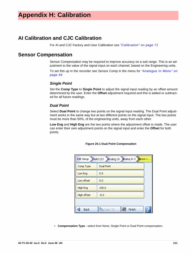
Appendix H: Calibration
AI Calibration and CJC CalibrationFor AI and CJC Factory and User Calibration see “Calibration” on page 71
Sensor CompensationSensor Compensation may be required to improve accuracy on a sub range. This is an ad-justment to the value of the signal input on each channel, based on the Engineering units.
To set this up in the recorder see Sensor Comp in the menu for “Analogue In Menu” onpage 44
Single PointSet the Comp Type to Single Point to adjust the signal input reading by an offset amountdetermined by the user. Enter the Offset adjustment required and this is added or subtract-ed for all future readings.
Dual PointSelect Dual Point to change two points on the signal input reading. The Dual Point adjust-ment works in the same way but at two different points on the signal input. The two points must be more than 50%, of the engineering units, away from each other.
Low Eng and High Eng are the two points where the adjustment offset is made. The user can enter their own adjustment points on the signal input and enter the Offset for both points.
• Compensation Type - select from None, Single Point or Dual Point compensation.
Figure 20.1 Dual Point Compensation
43-TV-25-30 Iss.2 GLO June 06 UK 211

Sensor Compensation
• Low Eng - only active when Full Range is not active. Set the Low limit for the Engineering units.
• Low Offset - enter an offset value that is offset against the Low Eng value.
• High Eng - only active when Full Range is not active. Set the High limit for the Engineering units.
• High Offset - enter an offset value that is offset against the High Eng value.
-10V
+10V
-10V
+10V
Single Point Sensor Compensation isused to offset the signal input by a userspecified amount over the full range.
Dual Point Sensor Compensation is used tooffset the signal input by a user specifiedamount against the Low and High Eng val-ues. The offset amount can vary throughoutthe signal input range.
Solid line shows without compensationand dotted line shows with compensation
Low Offset of 5
High Offset of -5
Figure App H.21 Sensor Compensation
100 High Eng
0 Low Eng
212 43-TV-25-30 Iss.2 GLO June 06 UK

Appendix I: Battery Data
Location: Processor Board
Safety Guidelines
• Keep batteries out of the reach of children, especially those batteries fitting within the limits of the truncated cylinder as defined in ISO/DP 8124/2.2.
• In the case of ingestion of a cell or battery the person involved should seek medical assist-ance promptly.
• It is of extreme importance that batteries are inserted into equipment correctly with regard to polarity (+ and -).
• Do not attempt to revive used batteries by heating, charging or other means.
• Do not dispose of batteries in fire.
• Do not dismantle batteries.
Type 6032
IEC CR2032
System Li/MnO2 /org.elyt.
Voltage 3.0 V
Cell Type Typical Capacity (mAh)
Weight
6032 230 mAh 3 gms
Approx Percent-age (%) of total
weight
Active Materials Maganese dioxide (mnO2) 29
Propylen carbonate (PC) 4.3
1,2 Dimethoxiethan (DME) 2.1
Lithium metal (Li) 2
Carbon (C) 0.9
Lithium perchlorate (LiCIO) 0.3
Passive Materials Stainless steel 57.6
Plastic 3.8
43-TV-25-30 Iss.2 GLO June 06 UK 213

Location: Processor Board
• Do not short circuit batteries.
• Batteries should be disposed of in accordance with local regulations, they must not be dis-posed of with normal refuse.
214 43-TV-25-30 Iss.2 GLO June 06 UK

Appendix J: Function Codes and Memory Maps
Modbus Memory Map Supplement:Refer to document Modbus® Serial Communications User manual, 51-52-25-66P, 04/06.
* Communications Inputs can be set by using Modbus function code 16NOTE: Some Modbus masters may require an offset of 1 for example instead of entering1800 enter 1801.
TotalisersTotaliser values in engineering units, 4 byte IEEE floats using 2 Modbus registers perreading.
Input Text messageThis facility allows a text message to be passed to the recorder to be annotated on thechart and added to the message log. The maximum length of the message is 32 bytes ofASCII characters, which need not be null-terminated.
It operates by utilising modbus function code 16 (0x10), Preset Multiple registers, and theunique address 0x0004 in the modbus global register map (Table A-1)
The modbus message format follows that shown in section 3.7 of the document cited.The Start Address will be 00 04, and the Byte Count of the number of bytes in the follow-ing text message. As 2 modbus registers are used to pass an address to function 16, theNumber of Addresses has to be back calculated from the required Byte Count to give thelowest integer such that (Number of Addresses) * 2 ≥ = Byte Count. For example if ByteCount = 4, then Number of Addresses = 2, but if Byte Count = 5, Number of Addresses =3.
As an example, to send the 5-character message Start to a slave address 02 the com-plete message would be:
The response follows the normal response for function code 16 given in section 3.7, andso to the above message the response would be: 02 10 00 04 00 03 CRC CRC
Start Address
(Hex)
End Address
(Hex)Description
See Appendix
51-52-25-66P
1800 185F Analogue Input Value (48 inputs max.) A.5
1880 18BF Communications Inputs (32 comms values max.)* A.6
2400 247F Extended Comms Inputs (64 comms values max.)* A.6
18C0 197F Pen Values (96 pens max.) A.7
1B00 1B7F Totalisers (64 totalisers max.) A.9
Slave Address
Function Code
Start Addr.High
Start Addr. Low
No Addr. High
No Addr.
Lo
Byte Count Data CRC CRC
02 10 00 04 00 03 05 53 74 61 72 74 CRC CRC
43-TV-25-30 Iss.2 GLO June 06 UK 215
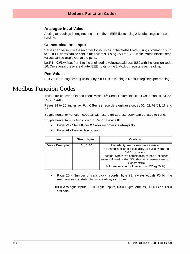
Modbus Function Codes
Analogue Input ValueAnalogue readings in engineering units. 4byte IEEE floats using 2 Modbus registers per reading.
Communications InputValues can be sent to the recorder for inclusion in the Maths Block, using command 16 up to 32 IEEE floats can be sent to the recorder. Using CV1 to CV32 in the Maths Block, these values can be displayed on the pens.i.e. P1 = CV1 will set Pen 1 to the engineering value set address 1880 with the function code 16. Once again these are 4 byte IEEE floats using 2 Modbus registers per reading.
Pen ValuesPen values in engineering units, 4 byte IEEE floats using 2 Modbus registers per reading.
Modbus Function CodesThese are described in document Modbus® Serial Communications User manual, 51-52-25-66P, 4/06.
Pages 14 to 25, inclusive. For X Series recorders only use codes 01, 02, 03/04, 16 and17.
Supplemental to Function code 16 with standard address 0004 can be used to send.
Supplemental to Function code 17, Report Device ID: • Page 23 - Slave ID for X Series recorders is always 05.• Page 24 - Device description
• Page 25 - Number of data block records, byte 23, always equals 05 for theTrendview range. data blocks are always in order.
00 = Analogue inputs, 02 = Digital inputs, 03 = Digital outputs, 06 = Pens, 09 =Totalisers.
Item Size in bytes Contents
Device Description 16d, 0x10 Recorder type+space+software versionThe length is extended to exactly 16 bytes by trailing
0x00 characters.Recorder type = is a combination of the OEM series
name followed by the OEM device name (truncated to 16 characters)
Software version is of the form nn.XX eg.00.FQ
216 43-TV-25-30 Iss.2 GLO June 06 UK

Index
A
AC Power ..................................................................13AI Calibration .........................................................71
Factory Calibration ..................................................71Acknowledge Alarm .............................................85Add Screen ................................................................79Administrator, Passwords .................................80Alarm Markers ......................................................125
Alarm Marker Flash Colours ...............................125Alarm Messages .....................................................92Alarm Relay Card Connections .....................20
4 and 8 Alarm Relay Cards ....................................21Channel Numbers ....................................................21
Alarm/Digital IO Diagnostics .......................103Alarm/Digital IO Menu ......................................47
Alarm Relay Card ....................................................47Digital IO Card .........................................................47
Alarm/Digital Input Specification ...............170Alarms Appendix D ............................................201Alarms Menu ...........................................................85
Acknowledge Alarm ...............................................85Configure Alarms ....................................................85View Alarms .............................................................85
Alarms, Pens ............................................................55All Messages ............................................................92Analogue In Menu .................................................44Analogue Input Card .....................................15, 16
CJC Connectors .......................................................17Channel Numbers ....................................................15Connection Details ..................................................16Current Input ............................................................16Diagnostics .............................................................101Signal Wiring ............................................................16
Analogue Out Menu .............................................46Analogue Output Card ........................................17
Channel Numbers ....................................................17Connection Details ..................................................18Diagnostics .............................................................103
Analogue Output Specifications ..................169Appendix A Quality and Safety ....................181Appendix B Maths Expressions ....................183Appendix C Thermocouple Connections .197Appendix D Alarms ............................................201Appendix E Ethernet ..........................................203Appendix F Fuzzy Logging .............................205Appendix G F sub zero Sterilisation ..........209Appendix H Calibration ................................... 211Appendix I Battery Data ..................................213Appendix J
Function Codes and Memory Maps ...................215
B
Backlights ............................................................... 167Barcodes for Batch ............................................... 75Batch Commands .................................................. 89Batch Mark on Chart .......................................... 88Batch Menu .............................................................. 74
Barcodes for Batch .................................................. 75Batch Setup/Control ............................................ 87
Batch Commands .................................................... 89Batch Mark on Chart .............................................. 88
Battery DataSafety Guidelines .................................................. 213
Battery Data Appendix I .................................. 213Battery Safety
Processor Board ..................................................... 213Brightness ................................................................. 77
C
CE Mark .................................................................. 181CJC Calibration .................................................... 73CJC Connectors .................................................... 17Cables ......................................................................... 12Calibration ............................................................... 71
AI Calibration .......................................................... 71Appendix H ............................................................ 211CJC Calibration ....................................................... 73Maintenance ........................................................... 168Sensor Compensation ........................................... 211User Calibration ....................................................... 71
Card Positions and Channel numbers ....... 43Card and Slot Positions ..................................... 14Change Passwords ............................................... 83Channel Mapping ............................................... 122
Map button ............................................................. 122Channel Mapping Objects .............................. 123Channel Mapping Widgets ............................. 122Chart Speeds ......................................................... 124Charts ......................................................................... 77Cleaning the Recorder ..................................... 167Client/Server Network ........................................ 64Commenting in Scripts ..................................... 195Commit Configuration ..................................... 104Commit Later, Configuration ........................ 104Comms Connections ............................................ 23Comms Diagnostics ........................................... 103
43-TV-25-30 Iss.2 GLO June 06 UK 217

Comms Menu ...........................................................61DNS/WINS/MDNS .................................................65IP Address .................................................................64Modbus ......................................................................62Ports ......................................................................61, 65SNTP ..........................................................................63TCP/IP .......................................................................64USB Comms Ports ...................................................61Web .............................................................................63
Comms ServerAdd Pens for Logging ...........................................152Add a Database .......................................................149Add a Database Server ..........................................149Add a Device ..........................................................150Add a new Device ..................................................145Administration ........................................................144Client Connections .................................................148Configure Database Logging ...............................145Connect to a Database ...........................................149Connect to a Database Server ..............................145Database ..................................................................144Database Logging ..................................................148Delete a Database ...................................................149Delete a Device ......................................................151Diagnostics ..............................................................144Edit a Device ...........................................................151Local Area Network ..............................................138Logging Configuration ..........................................151Network Settings ....................................................144OPC Clients ............................................................142Preferences ..............................................................145Remote Networks ...................................................139Setup .........................................................................149Shutdown .................................................................144Software Installation ..............................................135Summary of Logging Changes ............................152
Comms, Overview .................................................28Communications Connections
Ethernet Connections ..............................................23RS485 Connections .................................................23
Compact Flash Format ......................................90Configure Alarms ..................................................85Configure Menu ......................................................39
Edit Layout ................................................................78Layout ........................................................................78Load Layout ..............................................................79Passwords ..................................................................80Save Layout ..............................................................79Setup Menu ...............................................................40
Credits .........................................................................70
D
DC Input 24V ...........................................................23DC Power ..................................................................13DNS/WINS/MDNS .................................................65Data Storage
Overview ...................................................................28
Database Management Tool ..........................155Date Settings ............................................................83Daylight Saving ......................................................69Default Time Zone ................................................37Delete All Data .......................................................74Delete Screen ...........................................................79Deviation Alarm Markers ............................... 125Diagnostics
Alarm/Digital IO ....................................................103Analogue In ............................................................ 101Analogue Out .........................................................103Comms .....................................................................103Comms Server ........................................................144Media ....................................................................... 104Pulse Inputs .............................................................103
Diagnostics Messages .........................................92Diagnostics Status ..............................................101Digital IO Card Connections ..........................20
8 and 16 Digital Input/Output Cards ....................22Channel Numbers ....................................................23
Dimensions .................................................................8Discard Configuration ......................................104Display, Overview .................................................28Displaying Totals ...................................................59
E
ESS - Extended Security System ..................106Edit .............................................................................121Edit Layout ...............................................................78
Add Screen ................................................................79Delete Screen ............................................................79
Edit Setup ..................................................................41Edit, Screen .............................................................. 86Electrical Installation .........................................12
24V DC Input ...........................................................23AC Power ..................................................................13Alarm Relay Card Connections ............................20Analogue Input Card ...............................................15Analogue Output Card ............................................17Cables ........................................................................12Comms Connections ...............................................23DC Power ..................................................................13Digital IO Card Connections ................................. 20Fuses ..........................................................................12Installation Category ...............................................12Pulse Input Card ......................................................18SPCO Relay .............................................................. 24Signal Wiring ...........................................................12Transmitter Power Supply Card ............................19
EthernetConnections .............................................................. 23Rear Port ...................................................................61
Ethernet Appendix E ..........................................203Events Menu ............................................................66Export Now ...............................................................91
218 43-TV-25-30 Iss.2 GLO June 06 UK

F
F sub zero Sterilisation Appendix G ..........209Factory Calibration .............................................71Factory Menu ..........................................................70
AI Calibration ...........................................................71CJC Calibration ........................................................73Calibration ................................................................71Credits ........................................................................70Daylight Saving .......................................................69Firmware Upgrade ...................................................71Language ...................................................................69Line Hz ......................................................................70Temp.Units ................................................................69Time Zone .................................................................69
Field IO Menu .........................................................42Alarm Relay ..............................................................47Alarm/Digital IO ......................................................47Analogue In Menu ...................................................44Analogue Out ...........................................................46Digital IO ..................................................................47Pulse Input ................................................................49
Field IO Specification .......................................169Analogue Output ....................................................169Pulse Input Card .....................................................169
Finish .........................................................................104Commit ....................................................................104Commit Later .........................................................104Discard .....................................................................104
Firmware Credit System ..................................129Firmware Options ...............................................130
Firmware Credit System .......................................129Free Form Maths ....................................................130Remote Viewer .......................................................131
Firmware Upgrade ...............................................71First Time Password Setup - ESS ................106Free Form Maths .................................................130Full Maths ...............................................................190Full Maths & Script Processing ..................183Function Codes and Memory Maps ...........215Fuses ............................................................................12Fuzzy Logging Appendix F .............................205
G
General Menu .........................................................68Batch Menu ...............................................................74Factory .......................................................................70Groups .......................................................................75Ident ...........................................................................69Localisation ..............................................................69Printer Menu .............................................................75
Groups ........................................................................75
H
HardwareOptions ......................................................................33
Hazardous Voltages ................................................4Help Files ..................................................................37
I
IP Address .................................................................64Ident .............................................................................69Installation ..................................................................5
24V DC Input ...........................................................23Alarm Relay Cards ..................................................20Analogue Input Card ...............................................15Analogue Output Card ............................................17Comms Connections ...............................................23Digital IO Cards .......................................................20Electrical Installation ..............................................12Environment and Location .......................................5Instructions .................................................................9Mechanical Installation .............................................6Panel cut-out size .......................................................6Pulse Input Card .......................................................18SPCO Relay ..............................................................24Transmitter Power Supply Card ............................19
Installation Category ..........................................12
K
Keyboards .................................................................24
L
LED Flash Codes ................................................180Language ...................................................................69Layout Menu ............................................................78
Add Screen ................................................................79Delete Screen ............................................................79Edit Layout ...............................................................78Load Layout ..............................................................79Save Layout ..............................................................79
LevelPermissions Table ..................................................109
LevelsPasswords ..................................................................82
Load Layout .............................................................79Load Setup ................................................................40
43-TV-25-30 Iss.2 GLO June 06 UK 219

Local Area NetworkComms Server ........................................................138
Local Settings ..........................................................36Default Time Zone ...................................................37
Localisation ..............................................................69Daylight Saving ........................................................69Language ...................................................................69Line Hz ......................................................................70Temp.Units ................................................................69Time Zone .................................................................69
Log On/Off ................................................................36Logging .......................................................................53
M
Main Menu ................................................................38Alarms Menu ............................................................85Batch Commands .....................................................89Batch Mark on Chart ...............................................88Batch Setup/Control ................................................87Configure ...................................................................39Edit, Screen Menu ....................................................86Layout ........................................................................78Messages Menu ........................................................92Passwords ..................................................................80Process Menu ............................................................95Recording Menu .......................................................90Replay ........................................................................86Screen List .................................................................86Screen Menu .............................................................86Setup Menu ...............................................................40Status Menu ...............................................................96
Main Menu Access ................................................35Maintenance
Backlights ................................................................167Calibration ...............................................................168Cleaning ...................................................................167Operating Temperature .........................................167Touch Screen ...........................................................167
Maintenance Status ...............................................99Map button ..............................................................122Mark on Chart ...............................................120, 126Maths Error Messages ......................................195Maths Expressions ..............................................183
Full Maths ...............................................................190Full Maths & Script Processing ...........................183Maths Variable and Function Tables ...................184Script Function Application Examples ..............191
Maths Variable and Function Tables .........184Maths using commenting .................................195Max/Min Reset ........................................................95Mechanical Installation .......................................6
Dimensions ..................................................................8Installation Instructions .............................................9Mounting and Viewing Angles ................................6Panel Mounting ........................................................10Panel Mounting Clamp Installation ......................10
Panel cut-out size ....................................................... 6Media Diagnostics ..............................................104Memory Maps and Function Codes ........... 215Menu Bar .................................................................120
Screen ......................................................................121Menu Path .................................................................37Message Format ....................................................94Message List ............................................................93Message Types
Alarms .......................................................................92All ...............................................................................92Diagnostics ...............................................................92Security ......................................................................92System .......................................................................92User ............................................................................92
Messages Menu ......................................................92Alarm Messages .......................................................92All Messages ............................................................92Diagnostics Messages .............................................92Messages Format ..................................................... 94Messages List ...........................................................93Messages Types .......................................................92Security Messages ...................................................92System Messages ..................................................... 92User Messages ..........................................................92
Messages Types ......................................................92Modbus .......................................................................62Modbus Function Codes ..................................216Modbus, Comms ..................................................134Mounting and Viewing Angles ..........................6
N
Network SettingsComms Server ........................................................144
O
Operating Temperature ....................................167Options .......................................................................97
Hardware ...................................................................33Overview ....................................................................25
Comms .......................................................................28Data Storage .............................................................28Display .......................................................................28Options, Hardware ...................................................33QX Standard Screens ..............................................32Recorder Functionality ...........................................27Remote Control Viewer ..........................................29SX Standard Screens ...............................................31Security ......................................................................29USB Devices ............................................................29
220 43-TV-25-30 Iss.2 GLO June 06 UK

P
Panel Mounting ......................................................10Panel cut-out size ....................................................6Password Policy ..................................................107Password Security ...............................................105
Audit Trail ...............................................................108ESS ...........................................................................106First Time Password Setup - ESS .......................106Level Permissions Table .......................................109Log On/Off .............................................................105Users and Groups ...................................................105
Passwords .................................................................80Add User ...................................................................82Administrator ............................................................80Change Passwords ...................................................83Delete User ...............................................................83First Time Login ......................................................80Levels .........................................................................82Policy .........................................................................81Reset Passwords .......................................................83User Administration ................................................80Users ..........................................................................82
Passwords Setup First time ESS ..................106Pen Overview Status ............................................99Pen Pointers ...........................................................126Pens Menu ................................................................51
Alarms .......................................................................55Logging .....................................................................53Scale ...........................................................................52Totaliser .....................................................................57
Policy, Passwords .................................................81Ports
RS485 ........................................................................61Ports, Comms ..........................................................65Ports, Ethernet ........................................................61Power up ....................................................................35Preface ..........................................................................1Print Support ...........................................................24Printer Menu ...........................................................75Process Menu ..........................................................95
Max/Min ....................................................................95Totals - Start, Stop, Reset .......................................95
Process Screen Overview ................................ 119Processor Board
Battery Safety .........................................................213Protocols ......................................................................3Pulse Input Card ............................................18, 169
Channel Numbers ....................................................19Connection Details ..................................................19Diagnostics .............................................................103
Pulse Input Menu ..................................................49
Q
QX Standard Screens ...........................................32Quality and Safety
CE Mark ..................................................................181Safety .......................................................................181
Quality and Safety Appendix A ....................181
R
RS485Connections ..............................................................23Rear Port ....................................................................61
Recorder FunctionalityOverview
........................................................................27Recorder Setup .......................................................35
Default Time Zone ...................................................37Local Settings ...........................................................36LogOn/Off .................................................................36Main Menu ................................................................38Main Menu Access ..................................................35Menu Path .................................................................37
Recording Menu .....................................................90Device Selection ......................................................91Export Now ...............................................................91Export “busy” light ..................................................91Recording Methodology .........................................90Scheduled Export .....................................................91
Recording Status ..................................................101Remote Control Viewer
Overview ...................................................................29Remote Networks
Comms Server ........................................................139Remote Viewer ......................................................131Replay .................................................................86, 123Reset Passwords ....................................................83Reset Setup ...............................................................74Resistance Thermometers .................................16
S
SNTP ............................................................................63Client / Server Network ..........................................64
SPCO Relay .............................................................24SX Standard Screens
Overview ...................................................................31Safety .....................................................................2, 181
Hazardous Voltage .....................................................4Static Electricity .........................................................3Symbols .......................................................................2
43-TV-25-30 Iss.2 GLO June 06 UK 221

Safety Guidelines .................................................213Safety and Symbol Identification .....................3Save Layout ..............................................................79Save Setup .................................................................40Scale Menu ................................................................52Scheduled Export ...................................................91Screeen Activity
Deviation Alarm Markers .....................................125Screen Activity
Alarm Markers .......................................................125Charts Speeds .........................................................124Mark on Chart .........................................................126Pen Pointers ............................................................126Screen Markers .......................................................127
Screen Configuration .........................................119Menu Bar .................................................................120Process Screen Overview .....................................119Screen Designer Screens .......................................128Screen Menu Bar ....................................................121
Screen Designer ...................................................128Loading a Layout into a Recorder .......................128Loading a Template into a Recorder ...................128Software ...................................................................155
Screen List .................................................................86Screen Markers .....................................................127Screen Menu .......................................................76, 86
Charts .........................................................................77Screen Saver .............................................................76
Screen Menu Bar .................................................121Channel Mapping ...................................................122Edit ...........................................................................121Replay ......................................................................123
Screen Saver .............................................................76Brightness ..................................................................77Dim Saver ..................................................................77
Script Function Application Examples .....191Scripts using commenting ...............................195Security
Overview ...................................................................29Security Messages .................................................92Sensor Compensation
Analogue Input Calibration ..................................211Settings, Time and Date ......................................83Setup Menu ...............................................................40
AI Calibration ...........................................................71Alarm Relay ..............................................................47Alarm/Digital IO ......................................................47Alarms Menu ............................................................55Analogue In Menu ...................................................44Analogue Out ............................................................46Batch Menu ...............................................................74CJC Calibration ........................................................73Calibration .................................................................71Charts .........................................................................77Comms .......................................................................61Credits ........................................................................70Daylight Saving ........................................................69Digital IO ...................................................................47Edit Setup ..................................................................41Events Menu .............................................................66
Factory .......................................................................70Field IO .....................................................................42Firmware Upgrade ...................................................71General ......................................................................68Groups .......................................................................75IP Address .................................................................64Ident ...........................................................................69Language ...................................................................69Line Hz ......................................................................70Load Menu ................................................................40Localisation .............................................................. 69Logging .....................................................................53Modbus ......................................................................62Pens ............................................................................51Printer Menu .............................................................75Pulse Input ................................................................49SNTP ..........................................................................63Save Setup .................................................................40Scale Menu ...............................................................52Screen Saver .............................................................76TCP/IP .......................................................................64Temp.Units ................................................................69Time Zone .................................................................69Totaliser .....................................................................57Web ............................................................................63
Signal Wiring ...........................................................12Slave ID ......................................................................62Software ...................................................................155Software Installation, Comms Server .......135Spares List ...............................................................157Specification Tables ...........................................173Specifications ........................................................169Static Electricity, Safety .......................................3Status Menu .............................................................. 96
Alarm/Digital IO ....................................................103Analogue In ............................................................ 101Analogue Out .........................................................103Comms .....................................................................103Diagnostics .............................................................101General Status ..........................................................97IO Cards ....................................................................98Maintenance .............................................................99Media ....................................................................... 104Options ......................................................................97Pen Overview ...........................................................99Printing Screens .......................................................96Pulse Inputs .............................................................103Recording ................................................................101System .......................................................................96
Sterilisation .............................................................. 59Storage Media Format .......................................90Stylus ............................................................................35Symbols, Safety .........................................................2System Menu
General Status ..........................................................97IO Cards ....................................................................98Options ......................................................................97
System Messages ...................................................92System, Status ..........................................................96
222 43-TV-25-30 Iss.2 GLO June 06 UK

T
TCP/IP ........................................................................64DNS/WINS/MDNS .................................................65IP Address .................................................................64Ports ...........................................................................65
Technical Data & Specifications .................169Alarm/Digital Input ...............................................170Analogue Output ....................................................169Field IO ....................................................................169Input Range Performance Accuracy Table ........177Pulse Input Card .....................................................169Specification Tables ..............................................173
Temp.Units ................................................................69Thermocouple Connections
External Reference ................................................199How Thermocouples work ...................................197Internal Reference ..................................................198Thermocouple CJC Compensation .....................198
Thermocouple Connections Appendix C .197Time Settings ............................................................83Time Zone ..................................................................69Totaliser .....................................................................57
Displaying Totals .....................................................59Sterilisation ...............................................................59
Totals - Start, Stop, Reset ...................................95Touch Screen ..........................................................167Trademarks .................................................................1Transmitter Power Supply Card ....................19TrendManager Pro Software .........................155
TrendManager Pro .................................................155TrendServer Pro .....................................................155TrendViewer ...........................................................155
U
USB Comms Ports ................................................61USB Devices
Overview ...................................................................29USB Key Format ....................................................90User Calibration ....................................................71User Messages ........................................................92Users, Passwords ..................................................82
V,W,X,Y,Z
View Alarms .............................................................85Warnings and Precautions ..................................3Web ...............................................................................63
43-TV-25-30 Iss.2 GLO June 06 UK 223

224 43-TV-25-30 Iss.2 GLO June 06 UK


Sales and ServiceFor application assistance, current specifications, pricing, or name of the nearest Authorized Distributor, contact one of the offices below.
ASIA PACIFICControl ProductsAsia Pacific Headquarters Phone: +(65) 6355-2828Fax: +(65) 6445-3033
AustraliaHoneywell LimitedPhone: +(61) 2-9370-4500FAX: +(61) 2-9370-4525Toll Free 1300-36-39-36Toll Free Fax: 1300-36-04-70
China – PRC - BeijingHoneywell China Inc.Phone: +(86-10) 8458-3280Fax: +(86-10) 8458-3102
China – PRC - ShanghaiHoneywell China Inc.Phone: (86-21) 6237-0237Fax: (86-21) 6237-1237
China - Hong Kong S.A.R.Honeywell Ltd.Phone: +(852) 2953-6412Fax: +(852) 2953-6767
China – PRC - ChengduHoneywell China Inc.Phone: +(86-28) 6786-348Fax: +(86-28) 6787-061
China – PRC - GuangzhouHoneywell China Inc.Phone: +(86-20) 3879-1169Fax: +(86-20) 3879-1269
China – PRC - Shenzhen-Honeywell China Inc.Phone: +(86) 755-518-1226Fax: +(86) 755-518-1221
IndonesiaHoneywell Indonesia Pte Ltd.Phone: +(62) 21-535-8833FAX: +(62) 21-5367 1008
IndiaTATA Honeywell Ltd.Phone:+(91) 20687 0445/0446Fax: +(91) 20681 2243/ 687 5992
JapanHoneywell Inc.Phone: +(81) 3 5440 1425Fax: +(81) 3 5440 1368
South KoreaHoneywell Korea Co Ltd.Phone: +(822) 799-6167Fax: +(822) 792-9013
MalaysiaHoneywell Engineering Sdn BhdPhone: +(60-3) 7958-4988Fax: +(60-3) 7958-8922
New ZealandHoneywell LimitedPhone: +(64-9) 623-5050Fax: +(64-9) 623-5060Toll Free (0800) 202-088
PhilippinesHoneywell Systems (Philippines) Inc.Phone: +(63-2) 636-1661 /1662Fax: +(63-2) 638-4013
SingaporeHoneywell South East AsiaPhone: +(65) 6355-2828Fax: +(65) 6445-3033
ThailandHoneywell Systems (Thailand) Ltd.Phone: +(662) 693-3099FAX: +(662) 693-3085
Taiwan R.O.C.Honeywell Taiwan Ltd.Phone: +(886-2) 2245-1000FAX: +(886-2) 2245-3242
EUROPEAustria Honeywell Austria GmbHPhone: +43 (316)400123FAX: +43 (316)40017
Belgium Honeywell SA/NV Phone: +31(0)205656999FAX: +31(0)165330746
Bulgaria Honeywell EOOD Phone: +(359) 2 79 40 27 FAX: +(359) 2 79 40 90
Czech Republic Honeywell spol. s.r.o. Phone: +420-54324-5014FAX: +420-54324-5011
Denmark Honeywell A/S Phone: +(45) 39 55 55 55 FAX: +(45) 39 55 55 58
Finland Honeywell OY Phone: +358 (3) 2727625FAX: +358 (3) 2728600
France Honeywell SA Phone: +33 (0)1 60198075FAX: +33 (0)1 60198201
Germany Honeywell AG Phone: +49 (69)8064336FAX: +49 (69)806497336
Hungary Honeywell Kft. Phone: +36-1-451 4335FAX: +36-1-451 4343
Italy Honeywell S.p.A. Phone: +39 02 9214 6503FAX: +39 0292146377
The Netherlands Honeywell B.V. Phone: +31(0)205656999FAX: +31(0)165330746
Norway Honeywell A/S Phone: (45) 39 55 55 55
Poland Honeywell Sp. zo.o Phone: +48-22-6060900FAX: +48-22-6060901
Portugal Honeywell Portugal Lda Phone: +351 21 424 5000FAX: +351 21 424 50 99
Romania Honeywell Bucharest Phone: 40212110076FAX: +40 (40212103375)
Russian Federation (RF),Z.A.O. HoneywellPhone: +(7 095) 796 98 00FAX: +(7 095) 796 98 93
Slovak Republic Honeywell s.r.o. Phone: +421-2-58247 410FAX: +421-2-58247 415
Spain Honeywell S.A.Phone: +34 (0)91313 61 00FAX: +34 (0)91313 61 30
Sweden Honeywell AB Phone: +(46) 8 775 55 00 FAX: +(46) 8 775 56 00
Switzerland Honeywell AG Phone: +41 18552448FAX: +(41) 1 855 24 45
Turkey Honeywell Turkey A.S. Phone: +90 216 575 6600FAX: +90 216 575 6637
UkraineHoneywellTel : +380-44-201 44 74Fax: +380-44-201-44-75
United Kingdom Honeywell Control Systems Ltd. Phone: +44 (0)1334 655034FAX: +44 (0)1334 655554
MIDDLE EASTAbu Dhabi U A EMiddle East HeadquartersHoneywell Middle East Ltd.Phone: +971 2 4041220FAX: +971 2 4432536
Sultanate of OmanHoneywell & Co Oman LLC Phone: +968 701397FAX +968 787351
Saudia ArabiaHoneywell Turki Arabia Lim-itedPhone: +966-3-341-0140Fax: +966-3-341-0216
KuwaitHoneywell Kuwait KSCPhone: +965 2421327
AFRICAMediterranean & African DistributorsHoneywell SpA Phone: +39 (02) 250 10 604FAX: +39 (02) 250 10 659
South Africa (Republic of)Honeywell Southern AfricaHoneywell S.A. Pty. Ltd. Phone: +27 11 6958000FAX +27 118051504
NORTH AMERICACanada Honeywell LTD Phone: 1-800-737-3360 FAX: 1-800-565-4130
USAHoneywell Process Solu-tions, Phone: 1-800-343-0228FAX: 1-815-235-6545
LATIN AMERICAArgentina Honeywell S.A.I.C. Phone: +(54-11) 4383-3637 FAX: +(54-11) 4325-6470
Brazil Honeywell do Brasil & Cia Phone: +(55-11) 7266-1900 FAX: +(55-11) 7266-1905
Chile Honeywell Chile, S.A. Phone: +(56-2) 233-0688 FAX: +(56-2) 231-6679
Mexico Honeywell S.A. de C.V. Phone: +(52) 55 5259-1966 FAX: +(52) 55 5570-2985
Puerto Rico Honeywell Inc. Phone: +(809) 792-7075 FAX: +(809) 792-0053
TrinidadHoneywell Inc.Phone: +(868) 624-3964FAX: +(868) 624-3969
Venezuela Honeywell CA Phone: +(58-2) 238-0211 FAX: +(58-2) 238-3391
Honeywell Process SolutionsHoneywell 2500 W.Union Hills DrivePhoenix, Arizona 85027www.honeywell.com/imc/pi
43-TV-25-30June 2006© 2005 - 2006 Honeywell International Inc
.


![Tec. Qx. Synergy[1]](https://img.pdfslide.us/doc/110x75/542d349b219acd4e4b8b5301/tec-qx-synergy1.jpg)