Embed Size (px)
Citation preview

For Review O
nly
A 4-wire 3-phase power distribution network sensor for
monitoring minute load unbalance and harmonic noise and voltage spikes in power line
Journal: IEEE Sensors Journal
Manuscript ID: Draft
Manuscript Type: Regular Paper
Date Submitted by the Author: n/a
Complete List of Authors: Nath, Sagnik
Mondal, Joydeb; Indian Association For The Cultivation Of Science, Physical Chemistry Nath, Deb; Indian Association For The Cultivation Of Science, Physical Chemistry
Keywords: ACTU

For Review O
nly
A 4-wire 3-phase power distribution network sensor for monitoring minute load unbalance and harmonic
noise and voltage spikes in power line
Sagnik Nath, Joydeb Mondal and Deb Narayan Nath*
Department of Physical Chemistry,
Indian Association For The Cultivation Of Science,
2A&2B Raja. S. C. Mullick Road, Jadavpur, Kolkata-700032, India
Patent filed: 625/KOL/2013 dt. 29/05/2013
Ref. No. E-2/2271/2013-KOL
* - Corresponding author
E-mail : [email protected]
Page 1 of 10
123456789101112131415161718192021222324252627282930313233343536373839404142434445464748495051525354555657585960

For Review O
nly
Abstract:
In this work a sensor head based on simple phase
detection technique has been described which can
monitor minute load unbalance, harmonics and
voltage spikes in the power distribution network
and has the ability to switch off a distribution box
(DB) prior to a massive neutral failure. Typical
load-switcher can be easily coupled to the sensor
to retrieve balance in the power line. The unit is
very inexpensive compared to the present day
technique of monitoring phase and neutral
voltages and currents with voltage (VT) and
current (CT) transformers followed by
digitization and subsequent software analysis.
Keywords: 3-phase load unbalance monitor,
Phase sensitive detection, Harmonics and Noise
monitor in 3-phase power grid, Prior alarm to
neutral failure, Load switcher in 3-phase power
line.
I. Introduction
Load unbalance in a 4-wire, 3-phase power distribution network is a common nuisance. This causes wasteful energy in the form of large current in the Neutral wire which is normally rated at lower current capacity. Prolonged high current condition in Neutral wire eventually leads to unpredictable neutral failure, causing severe fire hazards and complete disruption of the voltage distribution among different phases leading to damage in equipments connected to lowest loaded phase due to voltage hike in that phase. Moreover, an unbalanced distribution network causes zero-sequence magnetic flux leakage in the sub-station transformer and becomes a source of electro-magnetic-interference (EMI) which impairs the functioning of sensitive electronic instruments. At the same time, triplens (the 3rd harmonic and higher) of the zero-sequence current enter the Ground from the Neutral at the sub-station transformer and interrupts communication using the Ground. Large harmonics content in the supply due to extensive use of non-linear loads (like SMPS, switched SCR), also causes hike in Neutral current [1]. The existence of current harmonics in power systems increases losses in the lines, decreases the power factor and causes timing errors in sensitive electronic equipment. It is interesting to note that harmonics produced by balanced 3-phase non-linear loads are positive sequence and negative sequence harmonics. But, single phase non-linear loads connected between phase and neutral in 4-wire 3-phase power line produces third order zero sequence current
harmonics which actually adds up in the neutral wire [2]. Present day market available monitoring systems are based on the concept of simultaneous sensing of voltages (VT) and currents (CT) at the three phases and also in the neutral wire over a wide dynamic range with sample rate ~ 16 ksps and all the power grid parameters are computed from the sampled data using a dedicated computer. However, the unit is very costly . This work describes a sensor head based on the phase-sensitive-detection (PSD) technique to output all the information regarding unbalance in the load and malfunctions in a 3-phase power grid and is substantially cheaper. In a power grid unlimited number of DB s ( Distribution Box) can be monitored. The sensor also monitors the harmonic noise ( from non-linear loads), voltage spikes in the power grid and gives prior alarm before a massive neutral failure at any DB. As per records available from maxim (www.maxim-ic.com/smartgrid), commercially available instruments employ 8-channel simultaneous sensing ADC (Analog-To-Digital Converter like MAX 11046; price 16 $ USD each) to monitor currents and voltages on the three phases and the neutral. The data is stored in memory for subsequent evaluation of total current, voltage, instantaneous power, active, reactive apparent energy, power factor and analysis of multiple harmonics. Considering a nominal voltage ~ 220 V and a measuring accuracy ~ 0.05% with a over-voltage limit 1.5 KV under fault the dynamic range specified is ~ 83 dB (http://www.maxim-ic.com/app-notes/index.mvp/id/4281). The instrument is very costly. A typical base station from Siemens (www.siemens.com) with analyzing software and sensor head costs ~ INR. 5,00,000/- and each sensor head (www.ekmmetering.com, www.intechopen.com ) costs ~INR. 40,000/-. It is true that such a system will give us all the information about a power grid but there still exists an urgent need for a simpler and cheaper solution to the problems of detection of load unbalance, harmonic noise and voltage spikes in the power system that often leads to neutral failure. Thus there has been always need for sensory system which will monitor load unbalance, harmonic noise, voltage spikes in a power distribution network with capability of shutting down the distribution block when these parameters exceed a safe limit and most importantly the sensory system should be cheap and simple and can be fabricated with easily available electronic components. Thus a cheap but sophisticated technique to monitor minute load unbalance, harmonics and voltage spikes in power line is highly wanted.
Page 2 of 10
123456789101112131415161718192021222324252627282930313233343536373839404142434445464748495051525354555657585960
For Review O
nly
The current sensing requirement is a difficult problem. Not only does the current sensor require a wider measurement dynamic range, it also needs to handle a wider frequency range because of the rich harmonic contents in the current waveform. The three most common sensor technologies today are the low resistance current shunt, the current transformer(CT), and the Hall effect sensor [3,4]. The CTs are used very commonly but these suffer from the nonideal behaviors of the high-permeability material used in the flux concentrator namely magnetic saturation and hysteresis, or memory. Moreover, with the superincrease in voltages (several hundred kV) in power distribution systems, the insulation of the CTs becomes more difficult and expensive. Hence, optical current sensors that do not suffer from electromagnetic interference are good substitutes for conventional CTs [5-7]. Recent developments in technology has also succeeded hybrid electro-optical fiber current sensors with high current rating [8-10]. There are recent reports for enhancement of performance of coil based sensors by various techniques [11,12]. Various other techniques by scavenging electro-mechanical energy from a current carrying conductor are also reported [13,14]. However, in this work we have sensed the imbalance in current in the three phases without actual measurement of the current. In effect , we have monitored the voltage of the neutral node with respect to ground only with high dynamic range (D.R.) and have obtained the current information without the limitation of the current transformer. Moreover, as the sensing node is only the neutral point where the potential is near ground, the technique can be used in very high voltage systems like electric-locomotive also.
II. The methodology
In this work we present a technique to monitor a power grid (a unique sensor for each DB) by detecting the phase components of NEUTRAL VOLTAGE PHASOR with respect to ground ( eNG) along the three phases of the power grid. We have employed phase-sensitive-detection ( Lock-in technique) with inherent very high dynamic range and extreme noise immunity.
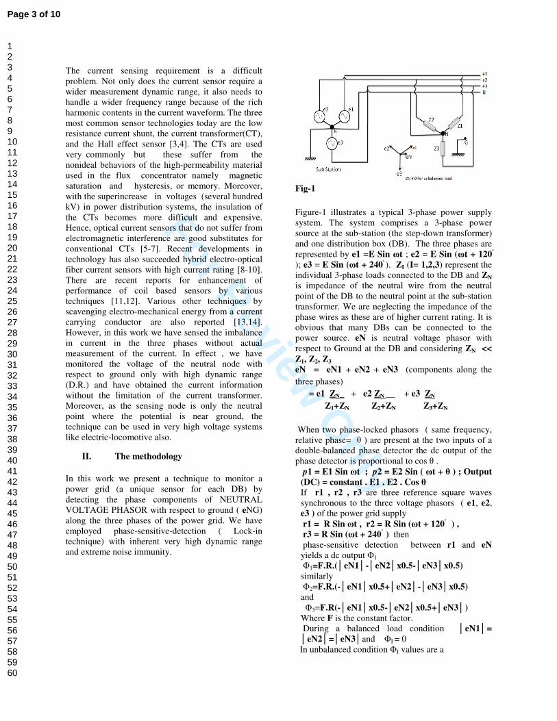
Fig-1
Figure-1 illustrates a typical 3-phase power supply system. The system comprises a 3-phase power source at the sub-station (the step-down transformer) and one distribution box (DB). The three phases are represented by e1 =E Sin ωt ; e2 = E Sin (ωt + 120
); e3 = E Sin (ωt + 240 ). ZI (I= 1,2,3) represent the individual 3-phase loads connected to the DB and ZN is impedance of the neutral wire from the neutral point of the DB to the neutral point at the sub-station transformer. We are neglecting the impedance of the phase wires as these are of higher current rating. It is obvious that many DBs can be connected to the power source. eN is neutral voltage phasor with respect to Ground at the DB and considering ZN <<
Z1, Z2, Z3
eN = eN1 + eN2 + eN3 (components along the
three phases)
= e1 ZN + e2 ZN + e3 ZN
Z1+ZN Z2+ZN Z3+ZN
When two phase-locked phasors ( same frequency, relative phase= θ ) are present at the two inputs of a double-balanced phase detector the dc output of the phase detector is proportional to cos θ .
p1 = E1 Sin ωt ; p2 = E2 Sin ( ωt + θ ) ; Output
(DC) = constant . E1 . E2 . Cos θ If r1 , r2 , r3 are three reference square waves synchronous to the three voltage phasors ( e1, e2, e3 ) of the power grid supply r1 = R Sin ωt , r2 = R Sin (ωt + 120 ) ,
r3 = R Sin (ωt + 240 ) then phase-sensitive detection between r1 and eN
yields a dc output Φ1 Φ1=F.R.(eN1-eN2x0.5-eN3x0.5) similarly Φ2=F.R.(-eN1x0.5+eN2-eN3x0.5)
and Φ3=F.R(-eN1x0.5-eN2x0.5+eN3)
Where F is the constant factor. During a balanced load condition eN1=
eN2=eN3and ΦI = 0 In unbalanced condition ΦI values are a
Page 3 of 10
123456789101112131415161718192021222324252627282930313233343536373839404142434445464748495051525354555657585960

For Review O
nly
measure of unbalance endowed with inherent high dynamic range ( > 80 dB ) and noise immunity (characteristics of Lock-in detection). The implementation of the concept is done in the following steps.
1. Generation of amplitude stabilized voltage references of e1 , e2 and e3
2. Generation of inverse of neutral voltage w.r.t. Ground, eGN = - k. eN
factor ; Neutral to Ground isolation ~ 100 MΩ . k = 0.091
3. Detection of phase components of eΦ2 , Φ3 ) along ei ( i= 1,2,3) employing phase-sensitive-detection with IC LM565 followed by amplification (1/4 LM324).
4. Precision rectification of eGN
averaging to yield ΦN, the information abneutral voltage w.r.t . Ground .
5. Removal of fundamental line frequency from eGN by a notch-filter followed by precision rectification and averaging to yield the harmonics and noise content Neutral voltage w.r.t. Ground.
6. Translation of Φ1 , Φ2 , Φ3 ,ΦN
are floating signals with reference to Neutral Point, into Ground-referenced signals to be processed by a central dedicated system .
7. Use of suitable comparator circuits to actuate alarms if any of Φ value exceeds set value .
Fig-2
measure of unbalance endowed with inherent high dynamic range ( > 80 dB ) and noise
The implementation of the concept is done in the
Generation of amplitude stabilized voltage
.
Generation of inverse of neutral voltage eN , k= scale
factor ; Neutral to Ground isolation ~ 100
Detection of phase components of eGN (Φ1 , ( i= 1,2,3) employing
detection with IC LM565 followed by amplification (1/4 LM324).
GN followed by , the information about
neutral voltage w.r.t . Ground .
Removal of fundamental line frequency filter followed by
precision rectification and averaging to yield the harmonics and noise content ΦHN in the Neutral voltage w.r.t. Ground.
N ,ΦHN , which are floating signals with reference to Neutral
referenced signals to be processed by a central dedicated system .
Use of suitable comparator circuits to value exceeds set
R1= 30K, 6W, 5%; Z1= 2V7, 250 mW; D1= 1N4148;
R2= 100 MΩ, 1/2 W, 2%, R3= 10 M
R4= 1 KΩ, 250 mW, 1%; LM310 is equipped with
offset null adjustment; Vn= ± 9V
In Fig-2 R1-Z1-D1 generates monostabilized reference signals (X1, X2, X3) in phase with the three supply voltage phasors e2 and e3. All the signals and the whole circuit including the DC power supplies are floating with respect to Ground and isreferenced to NEUTARL point.
Fig-3
z is the scaled eGN and is used to measure the neutral voltage after precision rectification and averaging. This is also usedharmonics content in the neutral voltage after filtering in a 50 Hz notch filter followed by precision filtering and averaging (Figthe same signal through a diode limiter and is fed to the input of the three PSDs built around thPLL565 ICs. Φ1 , Φ2 , Φ3 thus are measures of the phase components of neutral voltage along the three supply phasors.
Fig-4 C1= 100 MF, 25 V, electrolytic; R5= 10 K
mW, 1%, R6= 4K2 Ω, 250 mW, 1%; R7= 27K
R1= 30K, 6W, 5%; Z1= 2V7, 250 mW; D1= 1N4148;
, 1/2 W, 2%, R3= 10 MΩ , 250 mW, 1%;
, 250 mW, 1%; LM310 is equipped with
offset null adjustment; Vn= ± 9V
D1 generates mono-polar, stabilized reference signals (X1, X2, X3) in phase with the three supply voltage phasors e1,
. All the signals and the whole circuit including the DC power supplies are floating with respect to Ground and is essentially referenced to NEUTARL point.
and is used to measure the neutral voltage after precision rectification and averaging. This is also used to measure the harmonics content in the neutral voltage after filtering in a 50 Hz notch filter followed by precision filtering and averaging (Fig-3). vn is the same signal through a diode limiter and is fed to the input of the three PSDs built around three
thus are measures of the phase components of neutral voltage along
C1= 100 MF, 25 V, electrolytic; R5= 10 KΩ, 250
, 250 mW, 1%; R7= 27KΩ, 250
Page 4 of 10
123456789101112131415161718192021222324252627282930313233343536373839404142434445464748495051525354555657585960

For Review O
nly
mW, 1%; R8= 2K2 Ω , 250 mW, 1%; P1= 1K
Preset
Fig-4 depicts the basic phase-sensitive(PSD) for each phase. A first-order filter has been employed with C1 and the internal 3K6 resistor of LM565 and the time constant is on the order of 360 ms. A gain of x2.7 is employed with LM324 (1/4) and P1 is set to bring the PSD output at zero (i.e. at NEUTRL point) with vn shorted to NEUTRAL point (i.e. zero) but x signals being connected.
Fig-5
D1= 1N4148; R5= 10K Ω, 250 mW, 1%; R9= 1K
250 mW, 1%; R10= 10K Ω, 250 mW, 1%; C2=
470MF, 25 V, electrolytic.
Fig-5 depicts the circuit diagram of the precision rectifier and average used for measuring neutral voltage ΦN ( in Fig-3) and also the harmonics content ΦHN .
Fig-6
C3= 0.1 MF, polystyrene, 600V,5%; P2= 50K
Preset; R11= 470 KΩ , 250 mW, 1%; P3= 20 K
Preset; R12= 1 KΩ ,250 mW, 1%; R13 is parallel
combination of 100 KΩ and 150 KΩ
Fig-6 depicts the Passive Twin
differentiator tunable notch filter); three capacitors
, 250 mW, 1%; P1= 1K Ω 10T
sensitive-detector order filter has
been employed with C1 and the internal 3K6 Ω resistor of LM565 and the time constant is on the
A gain of x2.7 is employed with LM324 (1/4) and P1 is set to bring the PSD output at zero (i.e. at NEUTRL point) with vn shorted to NEUTRAL point (i.e. zero) but x
, 250 mW, 1%; R9= 1K Ω ,
, 250 mW, 1%; C2=
5 depicts the circuit diagram of the precision rectifier and average used for measuring neutral
3) and also the harmonics
polystyrene, 600V,5%; P2= 50KΩ 10T
, 250 mW, 1%; P3= 20 KΩ 10T
,250 mW, 1%; R13 is parallel
6 depicts the Passive Twin-T (bridged
differentiator tunable notch filter); three capacitors
are selected to be as identical as possible ; resistance
on the top must be exactly six times the bottom
resistance [15]. The bottom pre
frequency tuning at 50 Hz. The attenuation of the
filter when implemented in the circuit (Fig
Hz is much higher than 60 dB and the transmission at
150 Hz is on the order of 50%.
Experimental Data:
Fig-7. Experimentally monitored
Fig-8. Experimentally monitored Fig-7 and Fig-8 show the experimentally measured data of ΦN and Φperiod of 50 secs at a specific DB in the
are selected to be as identical as possible ; resistance
on the top must be exactly six times the bottom
. The bottom pre-set is adjusted for
requency tuning at 50 Hz. The attenuation of the
filter when implemented in the circuit (Fig-3) at 50
Hz is much higher than 60 dB and the transmission at
Experimentally monitored ΦN
Experimentally monitored ΦI (I=1,2.3)
8 show the experimentally and ΦI (I=1,2.3) over a
at a specific DB in the
Page 5 of 10
123456789101112131415161718192021222324252627282930313233343536373839404142434445464748495051525354555657585960

For Review O
nly
electrical power network of IACS.Fig-7 depicts the change of eNG (neutral voltage w.r.t ground) with time but there is no information of load unbalance in specific phases. However, from Fig-8 we get all the unbalance information. For our circuit design ΦI value of the most loaded phase is most negative and that for the least loaded phase is most positive. The 3rd phase will have intermediate ΦI value depending on its loading. In the Fig-8 at the start of the time phase-1 is most loaded and phase-3 is least loaded. However, at time on the order of 25 sec a heavy load is switched in phase-3 and phase-2 becomes the least loaded phase. Phase-1 remains the most loaded phase all the time.
Analysis of the data:
ΦI is related with eNI by the matrix relation ;
ΦI = K2 . A . eNI where
1.0 -0.5 -0.5
A = -0.5 1.0 -0.5
-0.5 -0.5 1.0
For our circuit parameters and configuration the constant K2 is negative.
Interesting features:
At any instant the most loaded ΦI value will be most negative (depending on the sign of K2 which is negative in our prototype design). At any instant correspondingly the least loaded ΦI value will be most positive. For the remaining phase which is loaded in between the ΦI value will lie in between the two extremes. ΦI values are unique and indicates the relative loading of the three phases with great precision but A is a Singular matrix ( DET A = 0 ) and analytical solution of eNI from ΦI values is not possible. This actually represents that individual currents in the three phases cannot be determined as addition of balanced currents in the three phases will not change the unbalance criterion. However, it should be noted that in condition of severe unbalance (one phase is heavily loaded in comparison to others) the current in loaded phase can be estimated fairly accurately.
Performance of the device:
1. ΦN measurement : time constant = 470 ms
; (this can be set at any value by R9C2 combination). If ΦN is the measured output then r.m.s neutral voltage with respect to ground is given by
2. eNG (r.m.s.) = 45 x ΦN ( DC) 3. ΦI measurement: time constant = 360 ms;
(this can be set at any value by adjusting C1); 1 V r.m.s. sig in @ eNG ( in phase ) = 1.536 V (DC). ΦI value has uncertainty of only a few mV ( the input offset voltage of LM324 is on the order of 1 mV and the gain in the circuit is 2.7, Fig-4 ) and considering a power supply of +/- 9 V the dynamic range of unbalance detection is on the order of 80 dB. Further if we consider the fact that this unbalance is in a power distribution network of nominal 240 V AC then the effective dynamic range of the unbalance measurement is 100 dB. In Fig-8 the spike in Φ3 approximately corresponds to 0.5 V r.m.s. voltage hike at neutral point due to switching on load in phase-3. Considering ZN ~ 160 m ohm (typically 200 m of 95 Sq mm cable, 150 A per phase), this indicates on the order of 3 A switching transient in phase-3 which may be caused by starting on of some motor.
4. Harmonic detection: In present prototype (the gain in amplifier A is one i.e A is absent, Fig-3) at 3rd harmonic (150 Hz) 1.6 V r.m.s. signal in eN triggers the LED. Actually it doesn’t mean anything but considering the fact that the dc sig out in the rectifier is in mV scale and sufficient amplification can be given ( say ~ 100) so that 16 mV r.m.s. can be easily detected corresponding to 100 mA of 3rd harmonic current in the neutral wire.
5. Voltage spikes: Voltage spikes are generated in the power supply network either from the source (at the sub-station transformer) or from switching reactive loads. These are manifested in the three phases and neutral points as spikes with respect to ground. As spike generation rarely occurs synchronously in all three phases, neutral point always reflects the spikes in the system. In our prototype the noise LED (Fig-3) gets triggered with 8 V, 1 ms pulse in the neutral. Implementation of the gain A
Page 6 of 10
123456789101112131415161718192021222324252627282930313233343536373839404142434445464748495051525354555657585960
For Review O
nly
(~100, Fig-3) will increase the sensitivity substantially. Normally a spike in the power line has bipolar characteristic and these are easily detected by the half-wave precision rectifier (Fig-5). For better performance regarding harmonics and spike detection a full wave precision rectifier can be used.
6. Cost-effectiveness: Now we come to the most significant point of this concept of 3-phase power monitoring and that is the incredible low cost of the device. In our prototype we have used a LM310 voltage follower with a 100 M ohm resistor (R2, Fig-2) which are not so cheap. This gives us a 100 M ohm isolation of the neutral to the ground. But considering the fact that the impedance between the neutral and ground is only a few ohms, a cheap voltage transformer (240 VAC to15 VAC , 1.5 W ) will serve the purpose as well and still a large number of DBs can be connected with such sensor. It is to be noted that present day costly commercial units also use voltage and current transformers. What is important is that the component cost of this sensor is only INR. 700/- (indigenous components) in comparison to the commercially available sensor heads (~INR. 40000/-).
Advantages: The unit can be used as a stand-alone unit to monitor the unbalance in load,harmonics and noise in the power line. Coupled with a set of comparators and logic circuits ( Fig-9) and actuator, it can safe guard
Fig-9 Automatic power line tripper.
and switch off a DB, if parameters cross safe limit, preventing fire and instrument damage. It is very easy to implement power management with this sensor. As
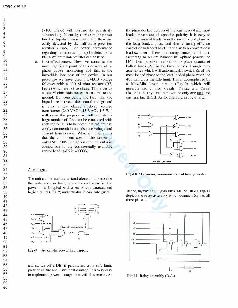
the phase-locked outputs of the least loaded and most loaded phase are of opposite polarity it is easy to switch quanta of loads from the most loaded phase to the least loaded phase and thus ensuring efficient control of balanced load sharing with a conventional load-switcher. There are many concepts of load switching to restore balance in 3-phase power line [16]. One possible method is to place quanta of ballast loads (ZB) in the three phases through relay assemblies which will automatically switch ZB of the most loaded phase to the least loaded phase when the ΦI s will cross the safe limit. This is accomplished by a Max-Min Logic circuit (Fig-10) which will generate six control signals, ΦImax and ΦImin (I=1,2,3). At any time there will be only one max and one min line HIGH. As for example, in Fig-8 after
Fig-10 Maximum, minimum control line generator
30 sec, Φ1max and Φ2min lines will be HIGH. Fig-11 depicts the relay assembly which connects ZB s to all three phases.
Fig-11 Relay assembly (R.A.)
Page 7 of 10
123456789101112131415161718192021222324252627282930313233343536373839404142434445464748495051525354555657585960

For Review O
nly
For the R.A. connected to phaseconnections are given as follows: Pin 1> Phase-1 Pin 2> Phase-2 Pin 3> Phase-3 Pin 4> Φ3min Pin 5> Φ2min Pin 6> Φ1max Pin 7> Neutral point Thus the R.A. pin connections for other phases are easily understood. It is to be noted that the ΦImin signals must be connected to the R.A.s via a six-bit latch which should be enabled only after a delay following the moment of crossing ovalues beyond the safe limit to avoid oscillation in the contacts. There should also be sufficient time delay between consecutive strobe of the latch.Conceptually it is possible to make set of ballast loads in the three phases which will be swiconsecutively if the first switching does not retrieve the balance. Of course, the first priority loads or the un-interrupted supplies should not be considered as ballast loads. A set of sensors connected to various DBs in a power distribution network can be easily fed to a base station equipped with a single channel 12 bit ADC and a computer. The input information (5 channels per DB) is de-multiplexed and after A/D conversion can be stored in the computer memory over a long period of time. Thus system troubleshooting will become much simpler. It is evident that the cost of such base station will be substantially cheaper than the present day technology. A typical circuit to convert the neutral referenced signals to ground referenced signals to be fed to the computer is shown in Fig-12. It uses opto-coupler chip and is self explanatory.
For the R.A. connected to phase-1 the pin
Thus the R.A. pin connections for other phases are easily understood. It is to be noted that the ΦImax and
s must be connected to the R.A.s via a bit latch which should be enabled only after a
delay following the moment of crossing of the ΦI values beyond the safe limit to avoid oscillation in the contacts. There should also be sufficient time delay between consecutive strobe of the latch. Conceptually it is possible to make set of ballast loads in the three phases which will be switched consecutively if the first switching does not retrieve the balance. Of course, the first priority loads or the
interrupted supplies should not be considered as
A set of sensors connected to various DBs in a power distribution network can be easily fed to a base
with a single channel 12 bit ADC and a computer. The input information (5 channels
multiplexed and after A/D conversion an be stored in the computer memory over a long
period of time. Thus system troubleshooting will become much simpler. It is evident that the cost of such base station will be substantially cheaper than the present day technology. A typical circuit to
rt the neutral referenced signals to ground the computer is shown
coupler chip and is self
Fig-12 Circuit for translating the Neutral referenced signals to Ground referenced signals.
Conclusion:
Thus we see that this technique, though cheap and simple, can provide us complete safeguard from imbalance, harmonics and spikes in a 4power line system. It overcomes the limitations of CTs and can be also implemented in very high voltage situations. It should be noted that over the last 30 years there had been a major change in power scenario both from the production and consumption point of views. In the old days technology the loads were more linear in nature. The low voltage supplies in almost all machines were either series or shunt linear regulators (bulky) which kept the power line noise free (silent). Present days, to enhance the efficiency and to cope with the power shortage , the technology is sweeping towards switchedpower supplies and in the process polluting the power lines with harmonics and spikes. popularity of photovoltaic or wind power based green energy in smart grid systems, the power lines are not clean as it used to be with dynamos (thermal or hydroelectricity) because of the use of SPWM technique. On the other hand, even the simple appliances will be equipped with hiin near future and side by side will be more vulnerable to high frequency harmonics, noises and spikes. Thus close monitoring of these parameters will become a necessity in every household.
Acknowledgement:
We express sincerely our gratitude to Mr. Siddharta Bose, Technical Officer, Electrical Engineering Division ,IACS for providing important technical information and help throughout the development of the project.
References:
[1] H. Jou, K. Wu, J. Wu et al., A threewire power filter comprising a threewire active power filter and a zigzag transformer, IEEE Trans. on Power Electronics
pp.252-259, 2008. [2] M. Ucar and E. Ozdemir, Control of a 3leg active power filter under non-
Circuit for translating the Neutral referenced signals to Ground referenced signals.
Thus we see that this technique, though cheap and simple, can provide us complete safeguard from imbalance, harmonics and spikes in a 4-wire 3-phase power line system. It overcomes the limitations of CTs and can be also implemented in very high
uations. It should be noted that over the major change in power
scenario both from the production and consumption point of views. In the old days technology the loads were more linear in nature. The low voltage supplies
lmost all machines were either series or shunt linear regulators (bulky) which kept the power line noise free (silent). Present days, to enhance the efficiency and to cope with the power shortage , the technology is sweeping towards switched-mode
plies and in the process polluting the power lines with harmonics and spikes. Moreover, with the popularity of photovoltaic or wind power based green energy in smart grid systems, the power lines are not clean as it used to be with dynamos (thermal or
because of the use of SPWM , even the simple home-
will be equipped with hi-tech intelligence in near future and side by side will be more vulnerable to high frequency harmonics, noises and
close monitoring of these parameters will become a necessity in every household.
We express sincerely our gratitude to Mr. Siddharta Bose, Technical Officer, Electrical Engineering Division ,IACS for providing important technical nformation and help throughout the development of
[1] H. Jou, K. Wu, J. Wu et al., A three-phase four-lter comprising a three-phase three-
ter and a zigzag transformer, Electronics, vol-23, no.1,
[2] M. Ucar and E. Ozdemir, Control of a 3-phase 4--ideal mains voltage
Page 8 of 10
123456789101112131415161718192021222324252627282930313233343536373839404142434445464748495051525354555657585960

For Review O
nly
condition, Electric Power Systems Research, vol-78, no.1, pp.58-73, 2008 [3] Maria-Alexandra Paun *, Jean-Michel Sallese and Maher Kayal; Hall Effect Sensors Design, Integration and Behavior Analysis ; J. Sens. Actuator Netw.
2013, 2, 85-97; doi:10.3390/jsan2010085 [4] A. Ajbl, M. Pastre, M. Kayal; A Fully Integrated Hall Sensor Microsystem for Contactless Current Measurement; Sensors Journal, IEEE.vol-13,issue:6; pp.2271-2278,2013 [5] B. Lee, Review of the present status of optical fiber sensors, Optical Fiber Technology; vol.9, pp.57-79,2003 [6] K.Grattan and T. Sun; Fiber optic sensor technology: An overview; Sens. Actuators A, Phys.
vol-82, nos. 1-3, pp.40-61,2000 [7] K. Barczak, Optical fibre current sensor for electrical power engineering, Bulletin of the Polish
Academy of Sciences,Technical Sciences, vol- 59, No. 4, 2011 [8] P. Orr; P. Niewczas; C. Booth; G. Fusiek; A. Dysko; F. Kawano; T. Nishida; P. Beaumont. An Optically-Interrogated Rogowski Coil for Passive, Multiplexable Current Measurement, Sensors
Journal, IEEE. vol-13, issue:6, pp.2053-2054, 2013 [9] A.O. Cremonezi; E.C. Ferreira; A.J.B. Filho; J.A.S. Dias.; A Fiber Bragg Grating RMS Current Transducer Based on the Magnetostriction Effect Using a Terfenol-D Toroidal-Shaped Modulator.; Sensors Journal, IEEE. vol-13, issue:2, pp.683-690,2013 [10] A.M. Bastos; J.W.M. Menezes; A.A. Kamshilin; A.S. Sombra; Hybrid Opto-Mechanical Current Sensor Based on a Mach-Zehnder Fiber Interferometer.; Sensors Journal, IEEE. vol- 14, issue:4, pp. 1056-1060, 2014 [11] C. Liu; Y. Dong; Resonant Coupling of a Passive Inductance-Capacitance-Resistor Loop in Coil-Based Sensing Systems; Sensors Journal. IEEE. vol-12, issue:12, pp.3417-3423, 2012 [12] I.A. Metwally; Performance Improvement of Slow-Wave Rogowski Coils for High Impulse Current Measurement; Sensors Journal, IEEE. vol-13,issue:2, pp.538-547,2013 [13] I. Paprotny, X. Qiliang, Wai Wah Chan, R.M. White, P.K. Wright; Electromechanical Energy Scavenging From Current-Carrying Conductors; Sensors Journal, IEEE. vol-13,issue:1,pp. 190-201, 2013 [14] Q.R. Xu, I. Paprotny, M. Seidel, R.M. White, P.K. Wright; Stick-On Piezoelectromagnetic AC Current Monitoring of Circuit Breaker Panels; Sensors Journal, IEEE. vol-13,issue:3, pp.1055-1064, 2013
[15] The Art of Electronics, Second edition, 1989 , P. Horowitz, W. Hill; Cambridge University Press; page- 280, 281 [16] Yanwei Zheng*, Lisheng Zou, Jian He, Yongyi Su, Zhiquan Feng , Fast Unbalanced Three-phase Adjustment based on Single-phase Load Switching, TELKOMNIKA , Vol. 11, No. 8, August 2013, pp. 4327~4334,e-ISSN: 2087-278X4327
Sagnik Nath is a B.E. student of Bengal Engineering and Science University in Electronics and Communication Engineering (3rd Year). He has worked as an intern in Dept. of Phys.Chem, IACS under Prof.D.N.Nath in summer-2012 and 2013.
Joydeb Mondal is a technical personnel in the Dept.of Phys.Chem., IACS. He is holding a Diploma on Radio Electronics from BHUSAN INSTITUTE OF RADIO ELECTRONICS, under W.B.U.T. and Graduation on Computer Hardware and Networking under "Netaji Subhas open University".
Page 9 of 10
123456789101112131415161718192021222324252627282930313233343536373839404142434445464748495051525354555657585960

For Review O
nly
Deb Narayan Nath is Senior Professor in the Dept. of Phys.Chem., IACS. He did his M.S. in Physics with specialization in Electronics and Radio Physics from Jadavpur University in 1975. His field of research is the study of the effect of magnetic field in radical pair systems. In the field of electronics he specializes in the techniques of retrieval of signals lost in noise.
Page 10 of 10
123456789101112131415161718192021222324252627282930313233343536373839404142434445464748495051525354555657585960