Embed Size (px)
Citation preview
Request for Propo
For: Replacement Spring Meado
Event
Bidder’s Electronic Question Due D(Refer to RFP Section 1.3.1 for more informatio
Mandatory Site Visit
Bid Submission Due Date (Refer to RFP Section 1.3.2 for more informatio
Dates are subject to change. All changes Division of Purchase and Property websi
Small Business Set-Aside (Refer to RFP Section 4.4.2.2 for more information.)
Status Not
Enti
Part
Sub
RFP Issued By State of New Jersey Department of the Treasury Division of Purchase and Property Trenton, New Jersey 08625-0230 Date: 10/20/08
sal 09-R-20688
Irrigation Control System w Golf Course
Date Time
ate n.) 12/5/08 5:00 PM
12/3/08
10:00 am
n.) 12/30/08 2:00 PM
will be reflected in Addenda to the RFP posted on the te.
Applicable
re Contract
ial Contract
contracting Only
Category I
II
III
Using Agency
State of New Jersey Department of Environmental Protection Bureau of Parks
2
Table of Contents
1.0 INFORMATION FOR BIDDERS..................................................................................................................................................... 3 1.1 PURPOSE AND INTENT .......................................................................................................................................................... 3 1.2 KEY EVENTS ............................................................................................................................................................................ 4
1.2.1 ELECTRONIC QUESTION AND ANSWER PERIOD ....................................................................................................... 4 1.2.2 SUBMISSION OF BID PROPOSAL .................................................................................................................................. 4
1.3 ADDITIONAL INFORMATION................................................................................................................................................... 5 1.3.1 ADDENDA: REVISIONS TO THIS RFP............................................................................................................................ 5 1.3.2 BIDDER RESPONSIBILITY .............................................................................................................................................. 5 1.3.3 COST LIABILITY............................................................................................................................................................... 5 1.3.4 CONTENTS OF BID PROPOSAL..................................................................................................................................... 5 1.3.5 BID OPENING................................................................................................................................................................... 6 1.3.6 PRICE ALTERATION........................................................................................................................................................ 6 1.3.7 BID ERRORS.................................................................................................................................................................... 6 1.3.8 JOINT VENTURE.............................................................................................................................................................. 7
2.0 DEFINITIONS ................................................................................................................................................................................. 8 2.1 GENERAL DEFINITIONS.......................................................................................................................................................... 8 2.2 CONTRACT SPECIFIC DEFINITIONS ..................................................................................................................................... 9
3.0 SCOPE OF WORK....................................................................................................................................................................... 10 3.1 SUMMARY OF WORK ............................................................................................................................................................ 10 3.2 SCHEDULE............................................................................................................................................................................ 10 3.3 BASIC MECHANICAL MATERIALS AND METHODS ........................................................................................................... 10 3.4 QUALITY ASSURANCE.......................................................................................................................................................... 10 3.5 PRODUCTS ........................................................................................................................................................................... 11 3.6 EXECUTION............................................................................................................................................................................ 13 3.7 BASIC ELECTRICAL MATERIALS AND METHODS............................................................................................................. 17 3.8 VERTICAL TURBIBE VARIABLE SPEED PREFABRICATED PUMP STATION................................................................... 20 3.9 IRRIGATION EQUIPMENT SPECIFICATIONS ..................................................................................................................... 36 3.10 SPECIFICATION DEVIATIONS OR SUBSTITUTIONS ....................................................................................................... 42 3.11 ADDITIONAL TERMS AND CONDITIONS .......................................................................................................................... 42
4.0 BID PROPOSAL PREPARATION AND SUBMISSION............................................................................................................... 44 4.1 GENERAL ............................................................................................................................................................................... 44 4.2 BID PROPOSAL DELIVERY AND IDENTIFICATION............................................................................................................. 44 4.3 NUMBER OF BID PROPOSAL COPIES................................................................................................................................. 44 4.4 BID PROPOSAL CONTENT ................................................................................................................................................... 44
4.4.1 FORMS THAT MUST BE SUBMITTED WITH BID PROPOSAL .................................................................................... 44 4.4.2 PROOFS OF REGISTRATION THAT MUST BE SUBMITTED WITH THE BID PROPOSAL........................................ 45 4.4.3 FORMS THAT MUST BE SUBMITTED BEFORE CONTRACT AWARD AND SHOULD BE SUBMITTED WITH THE BID PROPOSAL....................................................................................................................................................................... 46 4.4.4 TECHNICAL PROPOSAL ............................................................................................................................................... 46 4.4.5 ORGANIZATIONAL SUPPORT AND EXPERIENCE ..................................................................................................... 47 4.4.6 PRICE SCHEDULE......................................................................................................................................................... 49
5.0 SPECIAL CONTRACTUAL TERMS AND CONDITIONS............................................................................................................ 49 5.1 PRECEDENCE OF SPECIAL CONTRACTUAL TERMS AND CONDITIONS........................................................................ 49 5.2 CONTRACT AMENDMENT .................................................................................................................................................... 50 5.3 CONTRACTOR RESPONSIBILITIES ..................................................................................................................................... 50 5.4 SUBSTITUTION OF STAFF.................................................................................................................................................... 50 5.5 SUBSTITUTION OR ADDITION OF SUBCONTRACTOR(S) ................................................................................................. 50 5.6 OWNERSHIP OF MATERIAL ................................................................................................................................................. 51 5.7 DATA CONFIDENTIALITY ...................................................................................................................................................... 51 5.8 NEWS RELEASES.................................................................................................................................................................. 51 5.9 ADVERTISING ........................................................................................................................................................................ 51 5.10 LICENSES AND PERMITS ................................................................................................................................................... 52
3
5.11 CLAIMS AND REMEDIES..................................................................................................................................................... 52 5.11.1 CLAIMS......................................................................................................................................................................... 52 5.11.2 REMEDIES.................................................................................................................................................................... 52 5.11.3 REMEDIES FOR FAILURE TO COMPLY WITH MATERIAL CONTRACT REQUIREMENTS .................................... 52
5.12 STATE'S OPTION TO REDUCE SCOPE OF WORK ........................................................................................................... 52 5.13 SUSPENSION OF WORK..................................................................................................................................................... 52 5.14 CHANGE IN LAW.................................................................................................................................................................. 53 5.15 PUBLIC WORKS CONTRACT-ADDITIONAL AFFIRMATIVE ACTION REQUIREMENT .................................................... 53 5.16 ADDITIONAL WORK AND/OR SPECIAL PROJECTS ......................................................................................................... 53 5.17 FORM OF COMPENSATION AND PAYMENT..................................................................................................................... 54
5.17.1 PAYMENT TO CONTRACTOR - OPTIONAL METHOD............................................................................................... 55 5.18 MODIFICATIONS AND CHANGES TO THE NJ STANDARD TERMS AND CONDITIONS VERSION 07/27/07 ................ 55
5.18.1 PATENT AND COPYRIGHT INDEMNITY .................................................................................................................... 55 5.18.2 INDEMNIFICATION ...................................................................................................................................................... 55
6.0 PROPOSAL EVALUATION ......................................................................................................................................................... 56 6.1 PROPOSAL EVALUATION COMMITTEE .............................................................................................................................. 56 6.2 ORAL PRESENTATION AND/OR CLARIFICATION OF BID PROPOSAL............................................................................. 56 6.3 EVALUATION CRITERIA ........................................................................................................................................................ 56
6.3.1 TECHNICAL EVALUATION CRITERIA .......................................................................................................................... 57 6.3.2 BIDDER’S PRICE SCHEDULE....................................................................................................................................... 57 6.3.3 BID DISCREPANCIES.................................................................................................................................................... 57 6.3.4 EVALUATION OF THE BID PROPOSALS ..................................................................................................................... 57
6.4 NEGOTIATION AND BEST AND FINAL OFFER (BAFO)....................................................................................................... 57 7.0 CONTRACT AWARD................................................................................................................................................................... 58
7.1 DOCUMENTS REQUIRED BEFORE CONTRACT AWARD .................................................................................................. 58 7.1.1 REQUIREMENTS OF N.J.S.A. 19:44A-20.13-25 (FORMERLY EXECUTIVE ORDER 134).......................................... 58 7.1.2 SOURCE DISCLOSURE REQUIREMENTS................................................................................................................... 60
7.2 FINAL CONTRACT AWARD ................................................................................................................................................... 61 7.3 INSURANCE CERTIFICATES ................................................................................................................................................ 61 7.4 PERFORMANCE BOND ......................................................................................................................................................... 61
8.0 CONTRACT ADMINISTRATION.................................................................................................................................................. 62 8.1 CONTRACT MANAGER ......................................................................................................................................................... 62
8.1.1 STATE CONTRACT MANAGER RESPONSIBILITIES................................................................................................... 62 8.1.2 COORDINATION WITH THE STATE CONTRACT MANAGER ..................................................................................... 62
1.0 INFORMATION FOR BIDDERS 1.1 PURPOSE AND INTENT
4
This Request for Proposal (RFP) is issued by the Purchase Bureau, Division of Purchase and Property, Department of the Treasury on behalf of Department of Environmental Protection - Bureau of Parks. The purpose of this RFP is to solicit bid proposals for one (1) complete control irrigation system to be fabricated, delivered and installed within the Spring Meadow Golf Course, 4181 Atlantic Avenue, Farmingdale, NJ 07727. The intent of this RFP is to award a contract to that responsible bidder whose bid proposal, conforming to this RFP is most advantageous to the State, price and other factors considered. However, the State reserves the right to separately procure individual requirements that are the subject of the contract during the contract term, when deemed by the Director to be in the State’s best interest. The NJ Standard Terms & Conditions version 07/27/07 will apply to all contracts or purchase agreements made with the State of New Jersey. These terms are in addition to the terms and conditions set forth in this RFP and should be read in conjunction with them unless the RFP specifically indicates otherwise. 1.2 KEY EVENTS 1.2.1 ELECTRONIC QUESTION AND ANSWER PERIOD The Purchase Bureau will accept questions and inquiries from all potential bidders electronically via web form. To submit a question, please go to Current Bid Opportunities webpage or to http://ebid.nj.gov/QA.aspx Questions should be directly tied to the RFP and asked in consecutive order, from beginning to end, following the organization of the RFP. Each question should begin by referencing the RFP page number and section number to which it relates. Bidders are not to contact the Using Agency directly, in person, by telephone or by email, concerning this RFP. The cut-off date for electronic questions and inquiries relating to this RFP is indicated on the cover sheet. Addenda to this RFP, if any, will be posted on the Purchase Bureau website after the cut-off date (see Section 1.4.1. of this RFP for further information.) 1.2.2 SUBMISSION OF BID PROPOSAL In order to be considered for award, the bid proposal must be received by the Purchase Bureau of the Division of Purchase and Property at the appropriate location by the required time. ANY BID PROPOSAL NOT RECEIVED ON TIME AT THE LOCATION INDICATED BELOW WILL BE REJECTED. THE DATE AND TIME IS INDICATED ON THE COVER SHEET. THE LOCATION IS AS FOLLOWS: BID RECEIVING ROOM - 9TH FLOOR PURCHASE BUREAU DIVISION OF PURCHASE AND PROPERTY DEPARTMENT OF THE TREASURY 33 WEST STATE STREET, P.O. BOX 230 TRENTON, NJ 08625-0230 Directions to the Purchase Bureau can be found at the following web address: http://www.state.nj.us/treasury/purchase/directions.htm.
5
Note: Bidders using USPS Regular or Express mail services should allow additional time since USPS mail deliveries are not delivered directly to the Purchase Bureau. Procedural inquiries on this RFP may be directed to [email protected]. This e-mail address may also be used to submit requests to review bid documents. The State will not respond to substantive questions related to the RFP or any other contract via this e-mail address. To submit an RFP or contract related question, go to the Current Bidding Opportunities webpage or to http://ebid.nj.gov/QA.aspx. 1.3 ADDITIONAL INFORMATION 1.3.1 ADDENDA: REVISIONS TO THIS RFP In the event that it becomes necessary to clarify or revise this RFP, such clarification or revision will be by addendum. Any addendum to this RFP will become part of this RFP and part of any contract awarded as a result of this RFP. ALL RFP ADDENDA WILL BE ISSUED ON THE DIVISION OF PURCHASE AND PROPERTY WEB SITE. TO ACCESS ADDENDA, SELECT THE BID NUMBER ON THE BIDDING OPPORTUNITIES WEB PAGE AT THE FOLLOWING ADDRESS: http://www.state.nj.us/treasury/purchase/bid/summary/bid.shtml. There are no designated dates for release of addenda. Therefore interested bidders should check the Purchase Bureau "Bidding Opportunities" website on a daily basis from time of RFP issuance through bid opening. It is the sole responsibility of the bidder to be knowledgeable of all addenda related to this procurement. 1.3.2 BIDDER RESPONSIBILITY The bidder assumes sole responsibility for the complete effort required in submitting a bid proposal in response to this RFP. No special consideration will be given after bid proposals are opened because of a bidder's failure to be knowledgeable as to all of the requirements of this RFP. 1.3.3 COST LIABILITY The State assumes no responsibility and bears no liability for costs incurred by a bidder in the preparation and submittal of a bid proposal in response to this RFP. 1.3.4 CONTENTS OF BID PROPOSAL Subsequent to bid opening, all information submitted by bidders in response to the bid solicitation is considered public information, except as may be exempted from public disclosure by the Open Public Records Act, N.J.S.A. 47:1A-1 et seq., and the common law. Because the State proposes to negotiate and/or pursue a Best and Final Offer, bid proposals will not be made public until the Letter of Intent to Award is issued. A bidder may designate specific information as not subject to disclosure when the bidder has a good faith legal/factual basis for such assertion. The State reserves the right to make the
6
determination and will advise the bidder accordingly. The location in the bid proposal of any such designation should be clearly stated in a cover letter. The State will not honor any attempt by a bidder either to designate its entire bid proposal as proprietary and/or to claim copyright protection for its entire proposal. By signing the cover sheet of this RFP, the bidder waives any claims of copyright protection set forth within the manufacturer's price list and/or catalogs. The price lists and/or catalogs must be accessible to State using agencies and cooperative purchasing partners and thus have to be made public to allow all eligible purchasing entities access to the pricing information. All bid proposals, with the exception of information determined by the State or the Court to be proprietary, are available for public inspection after the Letter of Intent to Award is issued. At such time, interested parties can make an appointment with the Purchase Bureau to inspect bid proposals received in response to this RFP. 1.3.5 BID OPENING On the date and time bid proposals are due under the RFP, only the names of the bidders submitting bid proposals will be publicly announced. The contents of the bid proposals shall remain confidential until the Notice of Intent to Award is issued by the Director. 1.3.6 PRICE ALTERATION Bid prices must be typed or written in ink. Any price change (including "white-outs") must be initialed. Failure to initial price changes shall preclude a contract award from being made to the bidder. 1.3.7 BID ERRORS In accordance with N.J.A.C. 17:12-1.22, “Bid Errors,” a bidder may withdraw its bid as follows: A bidder may request that its bid be withdrawn prior to bid opening. Such request must be made, in writing, to the Supervisor of the Business Unit. If the request is granted, the bidder may submit a revised bid as long as the bid is received prior to the announced date and time for bid opening and at the place specified. If, after bid opening but before contract award, a bidder discovers an error in its proposal, the bidder may make written request to the Supervisor of the Business Unit for authorization to withdraw its proposal from consideration for award. Evidence of the bidder’s good faith in making this request shall be used in making the determination. The factors that will be considered are that the mistake is so significant that to enforce the contract resulting from the proposal would be unconscionable; that the mistake relates to a material feature of the contract; that the mistake occurred notwithstanding the bidder’s exercise of reasonable care; and that the State will not be significantly prejudiced by granting the withdrawal of the proposal. Note: a PB-36 complaint form may be filed and forwarded to the Division’s Contract Compliance and Audit Unit (CCAU) for handling. A record of the complaint will also be maintained in the Division’s vendor performance file for evaluation of future bids submitted. All bid withdrawal requests must include the bid identification number and the final bid opening date and sent to the following address:
Department of the Treasury Purchase Bureau, PO Box 230 33 West State Street – 9th Floor
7
Trenton, New Jersey 08625-0230 Attention: Supervisor, Business Unit
If during a bid evaluation process, an obvious pricing error made by a potential contract awardee is found, the Director shall issue written notice to the bidder. The bidder will have five days after receipt of the notice to confirm its pricing. If the vendor fails to respond, its bid shall be considered withdrawn, and no further consideration shall be given it. If it is discovered that there is an arithmetic disparity between the unit price and the total extended price, the unit price shall prevail. If there is any other ambiguity in the pricing other than a disparity between the unit price and extended price and the bidder’s intention is not readily discernible from other parts of the bid proposal, the Director may seek clarification from the bidder to ascertain the true intent of the bid. 1.3.8 JOINT VENTURE If a joint venture is submitting a bid proposal, the agreement between the parties relating to such joint venture should be submitted with the joint venture’s bid proposal. Authorized signatories from each party comprising the joint venture must sign the bid proposal. A separate Ownership Disclosure Form, Disclosure of Investigations and Actions Involving Bidder, Affirmative Action Employee Information Report, MacBride Principles Certification, and Business Registration or Interim Registration must be supplied for each party to a joint venture.
8
2.0 DEFINITIONS 2.1 GENERAL DEFINITIONS The following definitions will be part of any contract awarded or order placed as result of this RFP. Addendum – Written clarification or revision to this RFP issued by the Purchase Bureau. All-Inclusive Hourly Rate – An hourly rate comprised of all direct and indirect costs including, but not limited to: overhead, fee or profit, clerical support, travel expenses, per diem, safety equipment, materials, supplies, managerial support and all documents, forms, and reproductions thereof. This rate also includes portal-to-portal expenses as well as per diem expenses such as food. Amendment – A change in the scope of work to be performed by the contractor. An amendment is not effective until it is signed by the Director, Division of Purchase and Property. Bidder – An individual or business entity submitting a bid proposal in response to this RFP. Contract – This RFP, any addendum to this RFP, and the bidder’s proposal submitted in response to this RFP, as accepted by the State. Contractor – The bidder awarded a contract resulting from this RFP. Also referred to as the Implementation Contractor. Director – Director, Division of Purchase and Property, Department of the Treasury. By statutory authority, the Director is the chief contracting officer for the State of New Jersey. Division – The Division of Purchase and Property Evaluation Committee – A committee established by the Director to review and evaluate bid proposals submitted in response to this RFP and to recommend a contract award to the Director. Firm Fixed Price – A price that is all-inclusive of direct cost and indirect costs, including, but not limited to, direct labor costs, overhead, fee or profit, clerical support, equipment, materials, supplies, managerial (administrative) support, all documents, reports, forms, travel, reproduction and any other costs. No additional fees or costs shall be paid by the State unless there is a change in the scope of work. Joint Venture – A business undertaking by two or more entities to share risk and responsibility for a specific project. May – Denotes that which is permissible, not mandatory. Project – The undertaking or services that are the subject of this RFP. Request for Proposal (RFP) – This document which establishes the bidding and contract requirements and solicits bid proposals to meet the purchase needs of the using Agencies as identified herein. Shall or Must – Denotes that which is a mandatory requirement. Failure to meet a mandatory requirement will result in the rejection of a bid proposal as materially non-responsive. Should – Denotes that which is recommended, not mandatory.
9
State Contract Manager – The individual responsible for the approval of all deliverables, i.e., tasks, sub-tasks or other work elements in the Scope of Work as set forth in Sections 8.1, 8.1.1 and 8.1.2. Subtasks – Detailed activities that comprise the actual performance of a task. State – State of New Jersey. Subcontractor – An entity having an arrangement with a State contractor, where the State contractor uses the products and/or services of that entity to fulfill some of its obligations under its State contract, while retaining full responsibility for the performance of all of its [the contractor's] obligations under the contract, including payment to the subcontractor. The subcontractor has no legal relationship with the State, only with the contractor. Task – A discrete unit of work to be performed. Using Agency – The entity for which the Division has issued this RFP and will enter into a contract. 2.2 CONTRACT SPECIFIC DEFINITIONS Finished Spaces - Spaces other than mechanical and electrical equipment rooms, furred spaces, pipe and duct shafts, unheated spaces immediately below roof, spaces above ceilings, unexcavated spaces, crawlspaces, and tunnels. Exposed, Interior Installations - Exposed to view indoors. Examples include finished occupied spaces and mechanical equipment rooms. Exposed, Exterior Installations - Exposed to view outdoors or subject to outdoor ambient temperatures and weather conditions. Examples include rooftop locations. Concealed, Interior Installations - Concealed from view and protected from physical contact by building occupants. Examples include above ceilings and in duct shafts. Concealed, Exterior Installations - Concealed from view and protected from weather conditions and physical contact by building occupants but subject to outdoor ambient temperatures. Examples include installations within unheated shelters.

10
3.0 SCOPE OF WORK 3.1 SUMMARY OF WORK 3.1.1 The work, under this contract, shall consist of furnishing all materials, appliances, equipment and services necessary to complete the work outlined herein and as shown on the enclosed drawing, including but not limited to, the following.
3.1.2 Fabricate an irrigation control system including hardware and equipment, as set forth in these specifications that have been certified and approved by the New Jersey Department of Community Affairs (DCA).
3.1.3 Delivery to the site of an irrigation control system including DCA certified plans and specifications (IE, pumps, electrical, etc).
3.1.4 Installation of an irrigation control system. 3.2 SCHEDULE 3.2.1 The work is to be completed within ninety (90) calendar days after DCA certification is issued to the successful vendor. 3.3 BASIC MECHANICAL MATERIALS AND METHODS
3.3.1 GENERAL SUMMARY This Section includes the following:
Piping materials and installation instructions common to most piping systems. Dielectric fittings. Mechanical sleeve seals. Sleeves. Escutcheons. Grout. Mechanical demolition. Equipment installation requirements common to equipment sections. Concrete bases. Supports and anchorages.
3.3.2 SUBMITTALS The bidder should submit the following submittals: Welding certificates
3.4 QUALITY ASSURANCE
Steel Support Welding - Qualify processes and operators according to AWS D1.1, "Structural Welding Code--Steel." Steel Pipe Welding - Qualify processes and operators according to ASME Boiler and Pressure Vessel Code: Section IX, "Welding and Brazing Qualifications."
Comply with provisions in ASME B31 Series, "Code for Pressure Piping."
11
Certify that each welder has passed AWS qualification tests for welding processes involved and that certification is current.
Electrical Characteristics for Mechanical Equipment - Equipment of higher electrical characteristics may be furnished provided such proposed equipment is approved in writing and connecting electrical services, circuit breakers, and conduit sizes are appropriately modified. If minimum energy ratings or efficiencies are specified, equipment shall comply with requirements. 3.5 PRODUCTS 3.5.1 PIPE, TUBE, AND FITTINGS Refer to individual piping Sections for pipe, tube, and fitting materials and joining methods. Pipe Threads - ASME B1.20.1 for factory-threaded pipe and pipe fittings. 3.5.2 JOINING MATERIALS Refer to individual piping Sections for special joining materials not listed below. Pipe-Flange Gasket Materials - ASME B16.21, nonmetallic, flat, asbestos-free, 1/8-inch (3.2-mm) maximum thickness unless thickness or specific material is indicated. Plastic, Pipe-Flange Gasket, Bolts, and Nuts - Type and material recommended by piping system manufacturer, unless otherwise indicated. Solder Filler Metals - ASTM B 32, lead-free alloys. Include water-flushable flux according to ASTM B 813. Brazing Filler Metals - AWS A5.8, BCuP Series or BAg1, unless otherwise indicated. Welding Filler Metals - Comply with AWS D10.12. Solvent Cements for Joining Plastic Piping: ABS Piping: ASTM D 2235. CPVC Piping: ASTM F 493. PVC Piping: ASTM D 2564. Include primer according to ASTM F 656. PVC to ABS Piping Transition: ASTM D 3138.
3.5.3 DIELECTRIC FITTINGS Description - Combination fitting of copper alloy and ferrous materials with threaded, solder-joint, plain, or weld-neck end connections that match piping system materials. Insulating Material: Suitable for system fluid, pressure, and temperature. Dielectric Unions - Factory-fabricated, union assembly, for 250-psig (1725-kPa) minimum working pressure at 180 deg F (82 deg C).
12
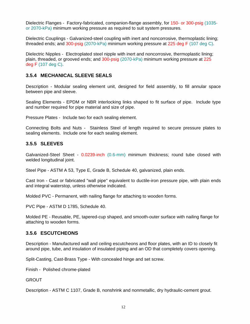
Dielectric Flanges - Factory-fabricated, companion-flange assembly, for 150- or 300-psig (1035- or 2070-kPa) minimum working pressure as required to suit system pressures. Dielectric Couplings - Galvanized-steel coupling with inert and noncorrosive, thermoplastic lining; threaded ends; and 300-psig (2070-kPa) minimum working pressure at 225 deg F (107 deg C). Dielectric Nipples - Electroplated steel nipple with inert and noncorrosive, thermoplastic lining; plain, threaded, or grooved ends; and 300-psig (2070-kPa) minimum working pressure at 225 deg F (107 deg C).
3.5.4 MECHANICAL SLEEVE SEALS Description - Modular sealing element unit, designed for field assembly, to fill annular space between pipe and sleeve. Sealing Elements - EPDM or NBR interlocking links shaped to fit surface of pipe. Include type and number required for pipe material and size of pipe. Pressure Plates - Include two for each sealing element. Connecting Bolts and Nuts - Stainless Steel of length required to secure pressure plates to sealing elements. Include one for each sealing element.
3.5.5 SLEEVES Galvanized-Steel Sheet - 0.0239-inch (0.6-mm) minimum thickness; round tube closed with welded longitudinal joint. Steel Pipe - ASTM A 53, Type E, Grade B, Schedule 40, galvanized, plain ends. Cast Iron - Cast or fabricated "wall pipe" equivalent to ductile-iron pressure pipe, with plain ends and integral waterstop, unless otherwise indicated. Molded PVC - Permanent, with nailing flange for attaching to wooden forms. PVC Pipe - ASTM D 1785, Schedule 40. Molded PE - Reusable, PE, tapered-cup shaped, and smooth-outer surface with nailing flange for attaching to wooden forms.
3.5.6 ESCUTCHEONS Description - Manufactured wall and ceiling escutcheons and floor plates, with an ID to closely fit around pipe, tube, and insulation of insulated piping and an OD that completely covers opening. Split-Casting, Cast-Brass Type - With concealed hinge and set screw. Finish - Polished chrome-plated GROUT Description - ASTM C 1107, Grade B, nonshrink and nonmetallic, dry hydraulic-cement grout.
13
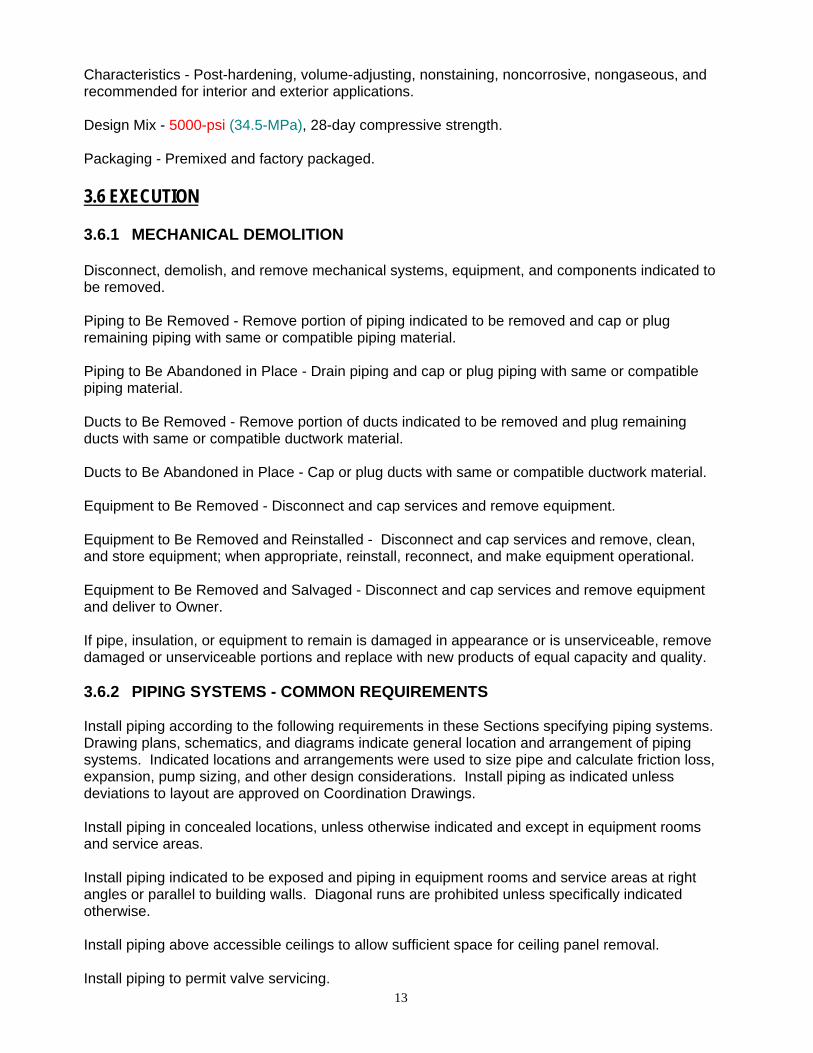
Characteristics - Post-hardening, volume-adjusting, nonstaining, noncorrosive, nongaseous, and recommended for interior and exterior applications. Design Mix - 5000-psi (34.5-MPa), 28-day compressive strength. Packaging - Premixed and factory packaged.
3.6 EXECUTION 3.6.1 MECHANICAL DEMOLITION Disconnect, demolish, and remove mechanical systems, equipment, and components indicated to be removed. Piping to Be Removed - Remove portion of piping indicated to be removed and cap or plug remaining piping with same or compatible piping material. Piping to Be Abandoned in Place - Drain piping and cap or plug piping with same or compatible piping material. Ducts to Be Removed - Remove portion of ducts indicated to be removed and plug remaining ducts with same or compatible ductwork material. Ducts to Be Abandoned in Place - Cap or plug ducts with same or compatible ductwork material. Equipment to Be Removed - Disconnect and cap services and remove equipment. Equipment to Be Removed and Reinstalled - Disconnect and cap services and remove, clean, and store equipment; when appropriate, reinstall, reconnect, and make equipment operational. Equipment to Be Removed and Salvaged - Disconnect and cap services and remove equipment and deliver to Owner. If pipe, insulation, or equipment to remain is damaged in appearance or is unserviceable, remove damaged or unserviceable portions and replace with new products of equal capacity and quality. 3.6.2 PIPING SYSTEMS - COMMON REQUIREMENTS Install piping according to the following requirements in these Sections specifying piping systems. Drawing plans, schematics, and diagrams indicate general location and arrangement of piping systems. Indicated locations and arrangements were used to size pipe and calculate friction loss, expansion, pump sizing, and other design considerations. Install piping as indicated unless deviations to layout are approved on Coordination Drawings. Install piping in concealed locations, unless otherwise indicated and except in equipment rooms and service areas. Install piping indicated to be exposed and piping in equipment rooms and service areas at right angles or parallel to building walls. Diagonal runs are prohibited unless specifically indicated otherwise. Install piping above accessible ceilings to allow sufficient space for ceiling panel removal. Install piping to permit valve servicing.
14
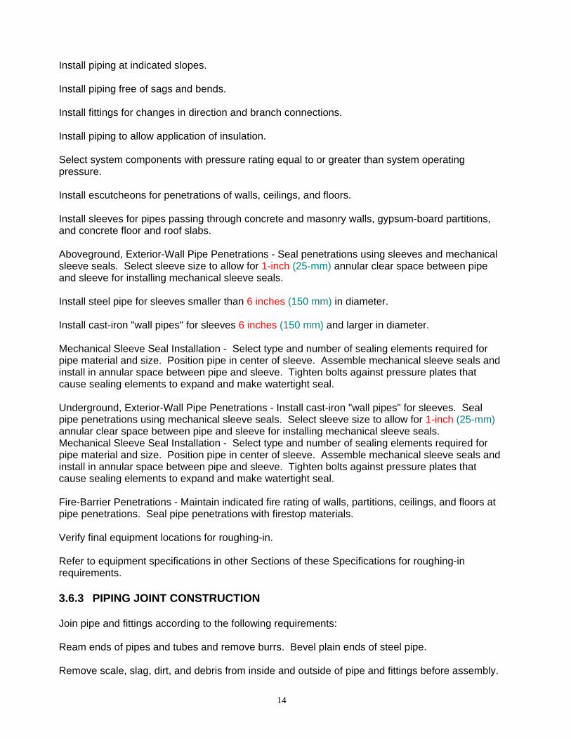
Install piping at indicated slopes. Install piping free of sags and bends. Install fittings for changes in direction and branch connections. Install piping to allow application of insulation. Select system components with pressure rating equal to or greater than system operating pressure. Install escutcheons for penetrations of walls, ceilings, and floors. Install sleeves for pipes passing through concrete and masonry walls, gypsum-board partitions, and concrete floor and roof slabs. Aboveground, Exterior-Wall Pipe Penetrations - Seal penetrations using sleeves and mechanical sleeve seals. Select sleeve size to allow for 1-inch (25-mm) annular clear space between pipe and sleeve for installing mechanical sleeve seals. Install steel pipe for sleeves smaller than 6 inches (150 mm) in diameter. Install cast-iron "wall pipes" for sleeves 6 inches (150 mm) and larger in diameter. Mechanical Sleeve Seal Installation - Select type and number of sealing elements required for pipe material and size. Position pipe in center of sleeve. Assemble mechanical sleeve seals and install in annular space between pipe and sleeve. Tighten bolts against pressure plates that cause sealing elements to expand and make watertight seal. Underground, Exterior-Wall Pipe Penetrations - Install cast-iron "wall pipes" for sleeves. Seal pipe penetrations using mechanical sleeve seals. Select sleeve size to allow for 1-inch (25-mm) annular clear space between pipe and sleeve for installing mechanical sleeve seals. Mechanical Sleeve Seal Installation - Select type and number of sealing elements required for pipe material and size. Position pipe in center of sleeve. Assemble mechanical sleeve seals and install in annular space between pipe and sleeve. Tighten bolts against pressure plates that cause sealing elements to expand and make watertight seal. Fire-Barrier Penetrations - Maintain indicated fire rating of walls, partitions, ceilings, and floors at pipe penetrations. Seal pipe penetrations with firestop materials. Verify final equipment locations for roughing-in. Refer to equipment specifications in other Sections of these Specifications for roughing-in requirements.
3.6.3 PIPING JOINT CONSTRUCTION Join pipe and fittings according to the following requirements: Ream ends of pipes and tubes and remove burrs. Bevel plain ends of steel pipe. Remove scale, slag, dirt, and debris from inside and outside of pipe and fittings before assembly.
15
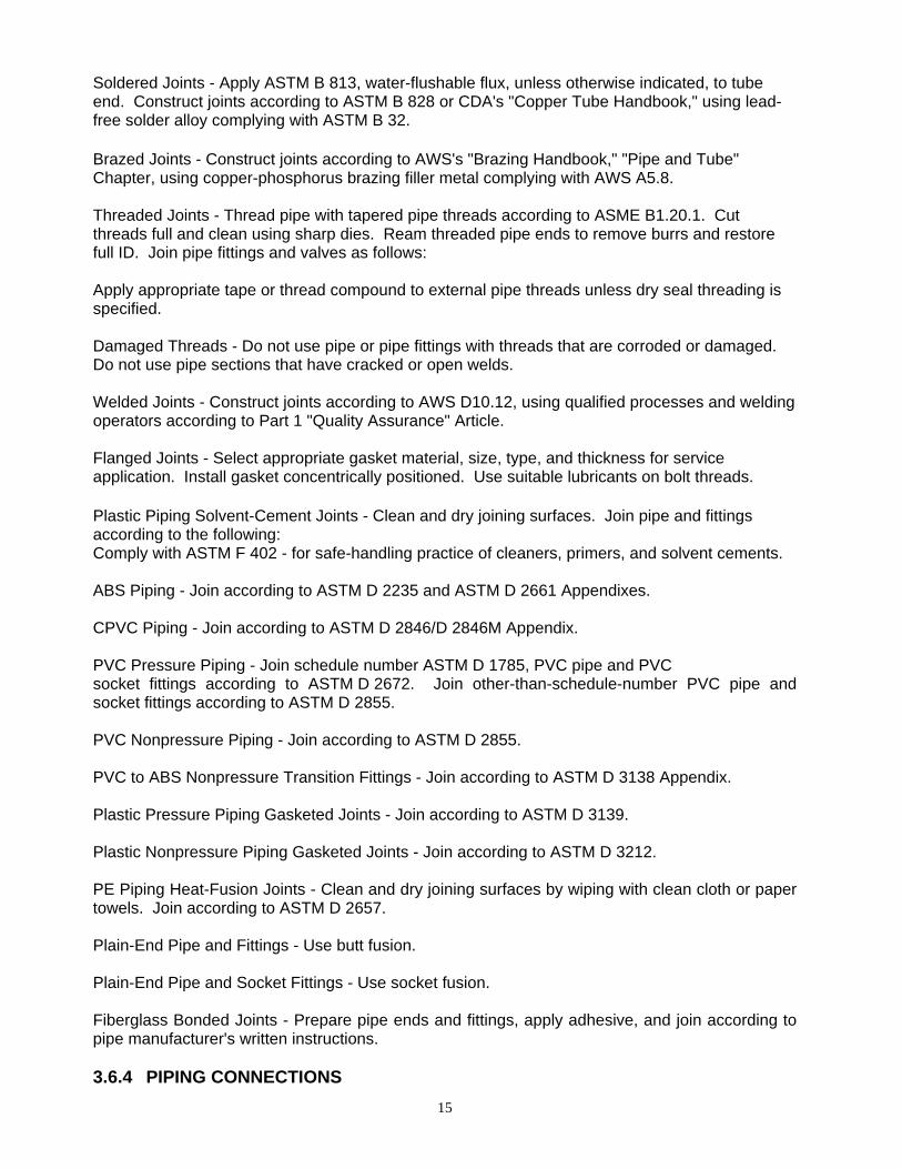
Soldered Joints - Apply ASTM B 813, water-flushable flux, unless otherwise indicated, to tube end. Construct joints according to ASTM B 828 or CDA's "Copper Tube Handbook," using lead-free solder alloy complying with ASTM B 32. Brazed Joints - Construct joints according to AWS's "Brazing Handbook," "Pipe and Tube" Chapter, using copper-phosphorus brazing filler metal complying with AWS A5.8. Threaded Joints - Thread pipe with tapered pipe threads according to ASME B1.20.1. Cut threads full and clean using sharp dies. Ream threaded pipe ends to remove burrs and restore full ID. Join pipe fittings and valves as follows: Apply appropriate tape or thread compound to external pipe threads unless dry seal threading is specified. Damaged Threads - Do not use pipe or pipe fittings with threads that are corroded or damaged. Do not use pipe sections that have cracked or open welds. Welded Joints - Construct joints according to AWS D10.12, using qualified processes and welding operators according to Part 1 "Quality Assurance" Article. Flanged Joints - Select appropriate gasket material, size, type, and thickness for service application. Install gasket concentrically positioned. Use suitable lubricants on bolt threads. Plastic Piping Solvent-Cement Joints - Clean and dry joining surfaces. Join pipe and fittings according to the following: Comply with ASTM F 402 - for safe-handling practice of cleaners, primers, and solvent cements.
ABS Piping - Join according to ASTM D 2235 and ASTM D 2661 Appendixes.
CPVC Piping - Join according to ASTM D 2846/D 2846M Appendix.
PVC Pressure Piping - Join schedule number ASTM D 1785, PVC pipe and PVC socket fittings according to ASTM D 2672. Join other-than-schedule-number PVC pipe and socket fittings according to ASTM D 2855. PVC Nonpressure Piping - Join according to ASTM D 2855. PVC to ABS Nonpressure Transition Fittings - Join according to ASTM D 3138 Appendix. Plastic Pressure Piping Gasketed Joints - Join according to ASTM D 3139. Plastic Nonpressure Piping Gasketed Joints - Join according to ASTM D 3212. PE Piping Heat-Fusion Joints - Clean and dry joining surfaces by wiping with clean cloth or paper towels. Join according to ASTM D 2657. Plain-End Pipe and Fittings - Use butt fusion. Plain-End Pipe and Socket Fittings - Use socket fusion. Fiberglass Bonded Joints - Prepare pipe ends and fittings, apply adhesive, and join according to pipe manufacturer's written instructions. 3.6.4 PIPING CONNECTIONS

16
Make connections according to the following, unless otherwise indicated: Install unions, in piping NPS 2 (DN 50) and smaller, adjacent to each valve and at final connection to each piece of equipment. Install flanges, in piping NPS 2-1/2 (DN 65) and larger, adjacent to flanged valves and at final connection to each piece of equipment. Dry Piping Systems - Install dielectric unions and flanges to connect piping materials of dissimilar metals. Wet Piping Systems - Install dielectric coupling and nipple fittings to connect piping materials of dissimilar metals.
3.6.5 EQUIPMENT INSTALLATION - COMMON REQUIREMENTS Install equipment to allow maximum possible headroom unless specific mounting heights are not indicated. Install equipment level and plumb, parallel and perpendicular to other building systems and components in exposed interior spaces, unless otherwise indicated. Install mechanical equipment to facilitate service, maintenance, and repair or replacement of components. Connect equipment for ease of disconnecting, with minimum interference to other installations. Extend grease fittings to accessible locations. Install equipment to allow right of way for piping installed at required slope. 3.6.6 CONCRETE BASES Concrete Bases - Anchor equipment to concrete base according to equipment manufacturer's written instructions and according to seismic codes at Project. Construct concrete bases of dimensions indicated, but not less than 4 inches (100 mm) larger in both directions than supported unit. Install dowel rods to connect concrete base to concrete floor. Unless otherwise indicated, install dowel rods on 18-inch (450-mm) centers around the full perimeter of the base. Install epoxy-coated anchor bolts for supported equipment that extend through concrete base, and anchor into structural concrete floor. Place and secure anchorage devices. Use supported equipment manufacturer's setting drawings, templates, diagrams, instructions, and directions furnished with items to be embedded. Install anchor bolts to elevations required for proper attachment to supported equipment. Install anchor bolts according to anchor-bolt manufacturer's written instructions. Use 3000-psi (20.7-MPa), 28-day compressive-strength concrete and reinforcement
3.6.7 ERECTION OF METAL SUPPORTS AND ANCHORAGES

17
Cut, fit, and place miscellaneous metal supports accurately in location, alignment, and elevation to support and anchor mechanical materials and equipment. Field Welding: Comply with AWS D1.1.
3.6.8 ERECTION OF WOOD SUPPORTS AND ANCHORAGES Cut, fit, and place wood grounds, nailers, blocking, and anchorages to support, and anchor mechanical materials and equipment. Select fastener sizes that will not penetrate members if opposite side will be exposed to view or will receive finish materials. Tighten connections between members. Install fasteners without splitting wood members. Attach to substrates as required to support applied loads.
3.6.9 GROUTING Mix and install grout for mechanical equipment base bearing surfaces, pump and other equipment base plates, and anchors. Clean surfaces that will come into contact with grout. Provide forms as required for placement of grout. Avoid air entrapment during placement of grout. Place grout, completely filling equipment bases. Place grout on concrete bases and provide smooth bearing surface for equipment. Place grout around anchors. Cure placed grout. 3.7 BASIC ELECTRICAL MATERIALS AND METHODS 3.7.1 GENERAL SUMMARY This Section includes the following: Electrical equipment coordination and installation. Sleeves for raceways and cables. Sleeve seals. Common electrical installation requirements.
3.7.2 SUBMITTALS The bidder should submit the following submittals:
18
Product Data: For each type of product indicated.
3.7.3 QUALITY ASSURANCE
Test Equipment Suitability and Calibration - Comply with NETA ATS, "Suitability of Test Equipment" and "Test Instrument Calibration."
3.7.4 COORDINATION
Coordinate arrangement, mounting, and support of electrical equipment:
To allow maximum possible headroom unless specific mounting heights that reduce headroom are indicated. To provide for ease of disconnecting the equipment with minimum interference to other installations. To allow right of way for piping and conduit installed at required slope. So connecting raceways, cables, wireways, cable trays, and busways will be clear of obstructions and of the working and access space of other equipment. Coordinate installation of required supporting devices and set sleeves in cast-in-place concrete, masonry walls, and other structural components as they are constructed. Coordinate location of access panels and doors for electrical items that are behind finished surfaces or otherwise concealed. Coordinate electrical testing of electrical, mechanical, and architectural items, so equipment and systems that are functionally interdependent are tested to demonstrate successful interoperability.
3.7.5 PRODUCTS
3.7.5.1 SLEEVES FOR RACEWAYS AND CABLES Steel Pipe Sleeves - ASTM A 53/A 53M, Type E, Grade B, Schedule 40, galvanized steel, plain ends. Cast-Iron Pipe Sleeves - Cast or fabricated "wall pipe," equivalent to ductile-iron pressure pipe, with plain ends and integral waterstop, unless otherwise indicated. Coordinate sleeve selection and application with selection and application of firestopping.
3.7.5.2 SLEEVE SEALS Description - Modular sealing device, designed for field assembly, to fill annular space between sleeve and raceway or cable.
Sealing Elements - EPDM interlocking links shaped to fit surface of cable or conduit. Include type and number required for material and size of raceway or cable.
Pressure Plates - Plastic. Include two for each sealing element.
19
Connecting Bolts and Nuts - Carbon steel with corrosion-resistant coating of length required to secure pressure plates to sealing elements. Include one for each sealing element. 3.7.6 EXECUTION
3.7.6.1 COMMON REQUIREMENTS FOR ELECTRICAL INSTALLATION Comply with NEC, latest edition. Measure indicated mounting heights to bottom of unit for suspended items and to center of unit for wall-mounting items. Headroom Maintenance - If mounting heights or other location criteria are not indicated, arrange and install components and equipment to provide maximum possible headroom consistent with these requirements. Equipment - Install to facilitate service, maintenance, and repair or replacement of components of both electrical equipment and other nearby installations. Connect in such a way as to facilitate future disconnecting with minimum interference with other items in the vicinity. Right of Way - Give to raceways and piping systems installed at a required slope.
3.7.6.2 SLEEVE INSTALLATION FOR ELECTRICAL PENETRATIONS Electrical penetrations occur when raceways, cables, wireways, cable trays, or busways penetrate concrete slabs, concrete or masonry walls, or fire-rated floor and wall assemblies.
Coordinate sleeve selection and application with selection and application of firestopping. Concrete Slabs and Walls - Install sleeves for penetrations unless core-drilled holes or formed openings are used. Install sleeves during erection of slabs and walls. Fire-Rated Assemblies - Install sleeves for penetrations of fire-rated floor and wall assemblies unless openings compatible with firestop system used are fabricated during construction of floor or wall.
Cut sleeves to length for mounting flush with both surfaces of walls. Extend sleeves installed in floors 2 inches (50 mm) above finished floor level. Size pipe sleeves to provide 1/4-inch (6.4-mm) annular clear space between sleeve and raceway or cable unless sleeve seal is to be installed. Seal space outside of sleeves with grout for penetrations of concrete and masonry. Fire-Rated-Assembly Penetrations - Maintain indicated fire rating of walls, partitions, ceilings, and floors at raceway and cable penetrations. Install sleeves and seal raceway and cable penetration sleeves with firestop materials. Roof-Penetration Sleeves - Seal penetration of individual raceways and cables with flexible boot-type flashing units applied in coordination with roofing work.
20
Aboveground, Exterior-Wall Penetrations - Seal penetrations using sleeves and mechanical sleeve seals. Select sleeve size to allow for 1-inch (25-mm) annular clear space between pipe and sleeve for installing mechanical sleeve seals. Underground, Exterior-Wall Penetrations - Install cast-iron "wall pipes" for sleeves. Size sleeves to allow for 1-inch (25-mm) annular clear space between raceway or cable and sleeve for installing mechanical sleeve seals. 3.7.6.3 FIRESTOPPING Apply firestopping to electrical penetrations of fire-rated floor and wall assemblies to restore original fire-resistance rating of assembly. 3.8 VERTICAL TURBIBE VARIABLE SPEED PREFABRICATED PUMP STATION
3.8.1 General To provide a single source responsibility for the manufacture, warranty, service and operation of a prefabricated, skid mounted, fully automatic variable speed pumping system for turf irrigation. The pumping system shall automatically maintain a constant discharge pressure regardless of varying flow demands within the station rating. Pumping system shall conform to the following specifications in all respects. This specification covers the minimum requirements, however, it should not be construed as all inclusive. It is the successful vendor's responsibility to include all necessary appurtenances to provide for a complete, automatic, smooth operating, and reliable pumping system. The manufacturer shall supply a complete set of general arrangement drawings, electrical power schematics, and control schematics in the operations & service manual. The entire station shall be U.L. Listed as a Packaged Pumping System. The vendor shall be responsible to disconnect, remove, and dispose of the existing skid mounted pump system, piping, valves, controls and electrical connections in order to facilitate the installation of the new system. 3.8.1.2 Manufacturer
The pumping system shall be of the type manufactured by FLOWTRONEX PSI Inc., Dallas, Texas, U.S.A., or approved equal.. The station shall be of the model number and capacities as shown in the proposal. For consideration of a proposed equal system, the vendor shall furnish the following data: A complete specification for the pumping system proposed as an equal.
A statement of full conformance to the following specifications signed by an officer of the manufacturer.
A general arrangement drawing showing overall dimensions and all piping layouts.
Complete submittal data for all major equipment (pumps, motors, filter, variable frequency drive (VFD), programmable controllers (PLC), valves, and motor starters). An electrical schematic showing power wiring. Installation list of 20 golf course variable frequency drive pumping systems of comparable size and performance that have been in operation for a minimum of 3 years. Location of closest VFD factory trained service centers.

21
Manufacturer's electrical control panel U.L. file number. Manufacturer’s complete pump station U.L. file number. A copy of manufacturer's certificate of insurance showing as a minimum, a general liability coverage of $1,000,000, and an excess liability coverage of $10,000,000. 3.8.2 Mechanical 3.8.2.1 Scope
Pump station shall be a completely skid mounted vertical turbine VFD pump station built by a single manufacturer. All equipment including but not limited to pumps, motors, piping, filters, valves, instrumentation and controls shall be mounted on a common structural steel base to form a complete operating pumping station. 3.8.2.2 Station Base
The pump station base shall be designed and fabricated to provide proper structural support for all attached equipment. The base shall supply sufficient rigidity to withstand the stresses of reasonable and competent transportation to site, off loading, installation, and operation. Main structural members shall be constructed from heavy weight channel or I-beam steel. Provisions shall be made in the station base for off-loading and handling the station at the site of installation. Base shall include 3/16” checkered deck plate and 1" steel plate mounted under pump discharge heads. All 3/16" deck plate and 1" steel plate shall be 100% seal welded to main structural members. Maximum allowable deflection on skid assembly to be 0.1” per linear foot. Skip welding is not acceptable. The pump steel skid shall completely cover the wet well. Attached is a drawing, Figure 1, which shows the architectural layout of the existing well house. The vendor shall be responsible to field verify all dimensions and clearance and provide six (6) sets of shop submittal drawings verifying the dimensional and structural adequacy of the station base. The shop submittal drawings shall be signed and sealed by a professional engineer licensed in the State of New Jersey. 3.8.2.3 Paint
The cleaned steel surface shall be immediately coated with an aliphatic polyurethane coating to a thickness of no less than 5 mils and applied through an electrostatic method to insure proper adhesion. This aliphatic polyurethane coating shall meet or exceed the following testing criteria: direct impact resistance of 140 in/lbs (per ASTM D 2794), taber abrasion loss no greater than 60.2 mg (per ASTM D 4060), adhesion to substrate of 1500 PSI (per ASTM D 4541), and salt fog resistance at 1400 hours (ASTM B117-85) to the following standards: rust rating of 10 (D 610), corrosion rating of 4 (D 1654), and blistering rating of 10 (D 714). Manufacturer shall provide a touch up kit for owners use. Powder coating will not be an accepted paint process since powder coating can not be field applied.. The vendor shall be responsible to clean, remove rust, prime, and paint the discharge piping to remain in the pump house. 3.8.2.4 Discharge Piping
22
All piping shall be constructed from ASTM A105 schedule 40 pipe or heavier as required to maintain a 3 to 1 pressure safety factor (including 1/16" corrosion allowance). All piping shall be hydrostatically tested to 150% of maximum shutoff pressure. Piping shall be painted as specified.
3.8.2.4 Bolts
All bolts used in the assembly of the pumping system shall be zinc plated to retardcorrosion. Anit-corrosion washers to be used on each side of fastener . 3.8.3 Pumps 3.8.3.1 Scope
Pump station manufacturer shall strictly adhere to the following pump specifications. All main pumps shall be of the same pump manufacturer. Two (2) fifty (50) horse power vertical turbine pumps shall be furnished and installed. One (1) three (3) horse power pressure maintenance pump shall be furnished and installed.
The system shall be able to maintain a discharge capacity of 1000 gpm at 120 psi working pressure. 3.8.3.2 Vertical Turbine Pumps
The main irrigation pump(s) shall be of the vertical turbine type. The vertical turbine pumps should be manufactured according to the standards of the Hydraulic Institute and to ANSI specification No. B58.1. The bowl assembly, column pipe, line-shaft, head shaft, and discharge head shall be of U.S. manufacture. The pumping systems manufacturer shall have a network of service centers which shall have available spare parts and trained pump technicians to handle service, repair and warranty procedures. 3.8.3.3 Discharge Head
The discharge head shall be of the fabricated steel type with a minimum 60,000 PSI tensile strength. The discharge shall have a working pressure of not less than 275 PSI and incorporate a 150 ANSI discharge flange. Complete discharge head shall be hydrostatically tested to a minimum of 413 PSI. A product lubricated high pressure stuffing box containing at least six rings of packing and two lantern rings shall be provided. Packing shall be compressed around shaft by an adjustable two-piece gland. Dual bypass tubing shall be included for proper packing lubrication and cooling. The discharge head stuffing box area shall also include a drain which will be piped back to the wet well. Discharge head to be designed to include leakless configuration. Discharge head shall incorporate an integral air separation chamber, allowing air to be discharged through an air release line mounted on top of head. Stuffing box bushing shall be SAE 660 Cast Iron. The head shaft shall be of the two piece type, 416 stainless steel and shall be turned and ground. The pump manufacturer shall include a method for adjusting the impeller running clearance at the top of the head shaft. Adequate space shall exist to couple the head shaft and the line shaft above the stuffing box. Coupling shall be extra heavy duty AISI 416 SS with a minimum service factor of 2 to 1. 3.8.3.4 Column Pipe
23
Column pipe should be A53, Grade B schedule 40 material, in inter-changeable sections not more than 10 feet in length. Pump line shaft shall be AISI 416 SS. The size of the shaft shall be no less than determined by ANSI specification B58.1, Section 4.2, Table 4. Bearing retainers shall be bronze with rubber bearings. 3.8.3.5 Pump Wet End
The pump bowls shall be ASTM A48 Class 30 cast iron free of detrimental defects. All bowls larger than 8" should be of the flanged type construction. All pump bowls shall have porcelain enamel lined water passageways for high efficiencies.
The impellers shall be C83800 bronze and of the enclosed type design. Pump shaft shall be AISI 416 SS turned and ground. The shaft shall be supported by bronze bearings above and below each impeller. The suction bell bearing shall be extra long and permanently greased packed and sealed with a bronze sand collar. A stainless steel clip on type inlet strainer shall be mounted on the bottom of each pump. Inlet area shall not be less than 4 times the suction bell inlet area. Pump bowl assemblies shall be as manufactured by Goulds Pump Company or approved equal. 3.8.3.6 Pressure Maintenance Pump
A pressure maintenance pump shall be provided to maintain system pressure during non irrigation periods. The pump shall be of the submersible type with stainless steel housing and stainless steel impeller. Pressure maintenance pump shall be as manufactured by Goulds.Pump or approved equal, shall be sized to prevent main pump cycling. Pump to be set on 6” high concrete pedestal.
3.8.4 Motors 3.8.4.1 Scope
Pump station manufacturer shall strictly adhere to the following specifications. 3.8.4.2 Vertical Hollow Shaft Motors
Motor(s) for irrigation pump shall be of the vertical hollow shaft high thrust design. Motor shall have a WP-I enclosure, 1.15 service factor, and class F insulation. Motors shall be wound for the starting configuration G. Design pump brake horsepower shall not exceed 98% of motor horsepower exclusive of service factor. Maximum pump run out horsepower shall not be greater than 8% higher than motor rating exclusive of service factor. Motor shall be rated for continuous duty and be designed to carry the maximum thrust load of the pump and will have B10 bearing life of no less than 5 years. Motors shall be rated and tagged for VFD service, proper ambient temperature and proper altitude per motor manufacturers recommendations. Motors shall be as manufactured by U.S. Electric, or Baldor or Reliance or equivalent. 3.8.4.3 Motor Space Heater
The pump station manufacturer shall provide on each pump motor a 120 volt, single phase space heater of ample size to prevent condensation from occurring within the motor during non operating periods. The space heater shall be de-energized when the motor is running.
24
3.8.4.4 Motor Pressure Maintenance Pump
Motor for pressure maintenance pump shall be a stainless steel submersible type with a 1.15 service factor. Motor shall be as manufactured by Franklin or approved equal. 3.8.5 Valves and Gauges 3.8.5.1 Scope
Pump station manufacturer shall strictly adhere to the following specifications. 3.8.5.2 Pump Check Valve
Pump check valves shall be bolted directly to the pump discharge heads. They shall be of the silent operating type that begin to close as forward velocity diminishes and be fully closed at zero velocity preventing flow reversal. Valve bodies shall be cast from ASTM-126C cast-iron or better and shall be free from blow holes, sand holes, and other impurities. The valve design shall incorporate a center guided, spring loaded poppet, guided at opposite ends and having a short linear stroke that generates a flow area equal to the pipe diameter. Internals shall be machined bronze disc, seat, and stem guide. Seat shall be Buna-N to provide resilient sealing. Dual disc style check valves are not acceptable. Valves shall be sized to permit full pump capacity to discharge through them without exceeding a pressure drop of 2.5 PSI. Check valve shall be as manufactured by Valmatic. Valves 4” and smaller to be pressure rated for 250 PSI, 6” to 10” to be pressure rated to 150 PSI. Valves 12” and larger check valves to be globe style with 150 PSI rating. 3.8.5.3 Pump Discharge Isolation Valves
Pump isolation valves shall be of the butterfly type with grooved ends to provide for expansion and vibration dampening and a lever operator. Lug style isolation valves are not acceptable. Valve body shall be constructed of ductile iron with a polyphenylene sulfide coating. Valve disc is rubber coated ductile iron. Valve shall be rated to 200 PSI. Isolation valve shall be as manufactured by Victaulic Or Grinnell Company .
3.8.5.4 Station Discharge Isolation Valve
Station isolation valve shall be installed on the discharge of the pump station to completely isolate the pumping system from the irrigation system. Valve shall be of the lug style butterfly type. Valve shall have one piece body cast from ASTM A126 cast iron. Stem shall be 416 stainless steel. Disc shall be nickel plated ductile iron. Stem bushings shall be Acetyl to prevent stem seizure to body during prolonged periods of non-use. Seat shall be Buna-N elastomer, one piece construction, and shall also form the flange sealing gaskets. Valves 8" and smaller shall have a lever operator. Valves 10" and larger shall have a gear operator with hand wheel. Valve shall be rated at 200 PSI bubble shutoff. Station isolation valve shall be as manufactured by Watts or approved equal 3.8.5.5 Pressure Relief Valve
A pilot operated modulating pressure relief valve shall be included. The valve shall be set 10 to 14 PSI above operating pressure and will relieve when inlet pressure exceeds spring setting on pilot. Valve shall be quick opening and slow closing to minimize surging. Pressure relief valve or lug valve shall not be used as integral part of normal irrigation pressure control. Discharge of relief valve shall be piped back to wet well. Valve body shall be Ductile iron with 125 LB inlet and
25
outlet flanges, and shall be rated for 250 PSI. A wye strainer shall be installed in the inlet side of the valve body to provide clean water to the CRL pilot. A wafer style butterfly valve shall be installed on the inlet of the relief valve. Specifications for this isolation valve will be the same as for the station isolation valve found later in the specification. The pressure relief valve shall work hydraulically and shall not be operated or opened from any electrical external source or control. The relief valve shall work solely as a safety for over pressure relief and shall not function as a normal part of the station controls. Relief valve shall be as manufactured by CLA-VAL no other manufacture shall be acceptable.
3.8.5.6 Pressure Gauge
A pressure gauge shall be mounted on the discharge header with a ½” isolation ball valve. All gauges shall be glycerin silicon filled to reduce wear due to vibration. Accuracy shall be within 2%. Gauge diameter shall be 4” - 3 1/2" minimum. Range shall be at least 50% higher than the highest pressure attainable from the pumps at shutoff head conditions. Stainless steel back & bronze internal. Pressure gauge shall be as manufactured by Wika or approved equal.
3.8.6 Electrical 3.8.6.1 Scope
To provide complete instrumentation and controls to automatically start, stop and modulate pump speed(s) to smoothly, efficiently and reliably pump variable flow rates at a constant discharge pressure. Full alarms and safety features needed to protect the equipment and irrigation piping system. All electrical controls shall be U.L. Listed as an Industrial Control Device. Vendor responsible to disconnect existing pump system from power supply, furnish and install new conduits and conductors, as needed, and re-establish power supply to new pump system. 3.8.6.2 Control Enclosure
Controls shall be housed in a NEMA 4 enclosure with integral latches. The control enclosure should be constructed of 12 gauge steel and the back plate assembly shall be constructed of 12 gauge steel.60” wide and larger to be 10 gauge or thicker. The enclosure shall be Powder coat painted or as specified in the paint specification listed under Section 2.0 Mechanical. All enclosure cut-outs to be done by laser for proper fit, sealing and coating retention. All indicating lights, reset buttons, speed potentiometer, selector switches and the operator interface device shall be mounted on enclosure door and also be rated NEMA 4. All internal components shall be mounted and secured to the removable back plate assembly. A closed type cooling system shall be included to cool the enclosure and reject heat from the VFD. Open type cooling systems allowing outside ambient air to enter the panel are not acceptable. No water line connections shall be permitted inside of the control enclosure. VFD status and internal parameters must be viewable without the opening of the enclosure door. Entire control panel shall provide minimum of 65KA short circuit protection. 3.8.6.3 Codes
The control panel with controls shall be built in accordance N.E.C., and U.L. standards. The pump station including electrical components and enclosure shall be labeled as a complete U.L. listed assembly with manufacturer's U.L. label applied to the pump station. All equipment and wiring shall be mounted within the enclosure and labeled for proper identification. All adjustments and maintenance shall be able to be done from the front of the control enclosure. A complete wiring
26
circuit and legend with all terminals, components, and wiring identification shall be provided. Main disconnect shall be interlocked with door. Cabinet to be lockable. 3.8.6.4 Lightning and Surge Arrester
All electrical equipment shall be protected by a U.L. Listed approved Category C and Category B surge arrester to suppress voltage surges on incoming power. The devise under IEEE C62.41 Category C will withstand a impulse of 10Kv/10Ka and Category B to withstand a ringwave of 6Kv/500a and a impulse of 6Kv/3Ka. Pass voltage for a 480v devise to the end equipment shall not exceed 1500V-1800V when subjected to a 8ms * 20ms waveshape resulting in the following performance statistics: 3720 joules minimum with a power dissipation of 82,500,000VA at 1800V maximum pass voltage to the protected equipment. Response time shall be less that 5 nanoseconds.
3.8.6.5 Main Disconnect
A fusible main disconnect shall be provided to completely isolate all controls and motor starting equipment from incoming power. Main disconnect shall have a through the door operator. Disconnect shall be as manufactured by ABB or Allen-Bradley. Disconnect shall not be rated as a service disconnect. Fuses shall be sized to protect equipment in the enclosure sufficiently to permit a minimum 65KA Short Circuit Current Rating (SCCR). 3.8.6.6 Control Power
Power for the controls shall be provided by a control power transformer which will provide low voltage, single phase power for the pumping system control operation. Control power transformer shall not be used for any other external load. The control power transformer shall be protected on the primary side by current limiting fuses of adequate size and voltage rating. All control components will be protected by time delay circuit breakers of adequate size. The control power transformer shall be as manufactured by Acme or approved equal.
3.8.6.7 Skid Conduit
All on skid conduit shall be flexible conduit with water tight connections at enclosure and termination device. All conduit shall be fastened to the skid every 24”.
3.8.6.8 Junction Boxes
All off skid devices requiring control interface shall be terminated in a junction box. This junction box shall be located at the skid edge nearest the installation point of the off skid device. Fertigation and monitoring systems shall be terminated in a NEMA 4 junction box located on the top left side of the main controls enclosure to allow end user connection.
3.8.7 Station Controls 3.8.7.1 Scope
To provide complete instrumentation and controls to automatically start, stop and modulate pump speed(s) to smoothly, efficiently and reliably pump variable flow rates at a constant discharge pressure. Full alarms and safety features needed to protect the equipment and irrigation piping system. All electrical controls shall be U.L. Listed as an Industrial Control Device. 3.8.7.2 Motor Starting Equipment
27
All motor starters for the pumping station shall be mounted on a single back panel in a single NEMA 4 enclosure as specified in section 3.10. Motor starters shall meet I.E.C. standards and shall be rated for a minimum of 1,250,000 operations. Each main irrigation motor shall have dual contactors, which are both electrically and mechanically interlocked to allow the VFD to operate on any of the motors. Motor overload relays shall be I.E.C. rated class 10 ambient compensated. Fuses shall supply short circuit protection to each motor and shall be rated for a minimum 200,000 amp interrupting capacity. Motor starters shall be as manufactured by Allen Bradley or approved equal. Motor over-loads shall be manual reset only. Auto-reset of motor overloads shall not permitted. 3.8.7.3 Variable Frequency Drive
The variable speed drive shall be a digital, pulse width modulation (PWM) variable frequency drive (VFD) with IGBT transistors. The VFD shall include a 3% input line reactor to protect against voltage transients. The VFD shall have a minimum wire to wire efficiency of 98.5%, and shall be rated up to 550 volt operation in order to eliminate nuisance tripping at marginally high voltage conditions. Incoming power end shall be protected by fast acting semiconductor fuses. Any VFD error messages shall be displayed on a 80 character LCD readout in English or any one of 11 other languages. The following fault protection circuits shall be included: Overcurrent (240%), Overvoltage (130%), Undervoltage (65%), Overtemperature (70 Deg. C), Ground fault, and motor overload. The VFD shall be capable of starting into a rotating load and accelerate or decelerate to setpoint without safety tripping. The VFD shall have an automatic extended power loss ride through circuit which will utilize the inertia of the pump to keep the drive powered. Minimum power loss ride-through shall be one cycle based on full load and no inertia. The VFD shall be optimized for a 3 kHz carrier frequency to reduce motor noise. The VFD shall employ three current limit circuits to provide "tripless" operation. The following operating information shall be displayed on the VFD LCD: KWH, elapsed time, output frequency (Hz), motor speed (RPM), motor current (amps), and voltage. Line reactor will be installed on input of VFD to protect against voltage transients. The VFD LCD display shall continuously scroll through all operating information and shutdown faults while the drive is running and while stopped. The information shall be viewable through a water tight plexiglass window on the control panel door as specified in Section 3.10. VFD shall be as manufactured by ABB. 3.8.7.4 Pressure Transducer
Pressure transducer shall be utilized for providing all pressure signals for the control logic. Pressure transducer shall be a solid-state bonded strain gage type with an accuracy of plus/minus 0.20% and constructed of 316L stainless steel. Transducer shall be rated for station discharge pressure and shall provide gauge pressure output, rather than an absolute. Pressure transducer constructed of plastic is not acceptable. Threshold transducers are not acceptable. Pressure transducer shall be as manufactured by GEMS or approved equal. 3.8.7.5 Flow Meter
The pump station shall have a flow sensor installed which will provide the pump station flow rate and total flow through the operator interface device (OID) as specified in Section 7.70. The flow sensor shall be a six bladed design which provides a low impedance signal proportional to the flow. The accuracy shall be plus/minus 2% of actual flow rate between flow velocities of 1-30 ft./sec. A flow meter run shall be included with a minimum of 5 pipe diameters straight run upstream and 2.5 pipe diameters downstream for proper meter accuracy. Flow sensor model must have internal noise filtering feature. Flow sensor wire must be encased in ½”liquid tight conduit from sensor to enclosure. Flow sensor shall be as manufactured by Data Industrial or approved equal.
28
3.8.7.6 Controls
All control logic shall be handled by an industrial grade programmable logic controller (PLC) with a 160 character LED industrial operator interface providing data entry and read-out capabilities. PLC shall provide demand controlled sequential pump start-up, shutdown and safety features through its pressure sensing, flow sensing and voltage sensing devices. PLC shall have LED indicators for input, output, and six diagnostic read-outs showing PC Run, CPU Fault, and two communications, (battery and force). An LED visual status light is provided for each I/O to indicate on/off status. PLC shall be provided with a built in EEPROM, capacitor, and battery for memory backup. All logic for system control, timing, and control of VFD speed shall be handled by the PLC. A separate set point controller is not acceptable. PLC shall have a built in clock calendar. The PLC shall be as manufactured by WAGO or approved equal. Control software shall be parameter driven, fully documented, and allow user to easily change ALL operational parameters. Standard control features and equipment which need to be included as a minimum are as follows: Alarms and shutdowns:
Low discharge pressure High discharge pressure (Attempt restart)* Low water level ( attempt restart ) Phase loss (Attempts restart)* Low voltage (Attempts restart)* Phase unbalance (Attempts restart)* Phase reversal Individual motor overload/phase loss (indicates which individual motor was shut down) Manual reset only. Automatic reset is not acceptable. VFD fault (shutdown VFD pump only and attempts restart)* * Three unsuccessful restarts in 60 minute period will give hard shutdown.
All alarms will be indicated by a red general alarm light. Specific alarm conditions along with procedures for correction will be displayed in English on the operator interface display (OID).
Panel face switches and lights: Controls shall be designed so operator can discretely start and stop all pumps in all modes of operation including manual mode, operator interface failure, VFD bypass and PLC bypass modes with enclosure doors closed and disconnect switch fully engaged. Enclosure shall include the following switches/ or indicator lights: Individual pump run lights Individual pump on/off switches System Hand / Off / Automatic switch Mode select switch – allows automatic bypass mode of operation which can be used in the event of VFD failure VFD selector switch – in manual mode, allows user to select which pump will be run of the VFD Reset – Acknowledges pump station alarms Speed potentiometer – in manual mode allows user to adjust VFD pump speed
29
Low discharge pressure over-ride switch – disables low discharge pressure alarm Individual pump run lights Individual pump on/off switches System Hand / Off / Automatic switch Mode select switch – allows automatic bypass mode of operation which can be used in the even of VFD failure VFD selector switch – in manual mode, allows user to select which pump will be run of the VFD
Reset – Acknowledges pump station alarms
Speed potentiometer – in manual mode allows user to adjust VFD pump speed
Low discharge pressure over-ride switch – disables low discharge pressure alarm
PLC bypass switch allows user to manually operate pumps should PLC fail. The bypass switch shall be din-rail mounted inside the enclosure. When in bypass the station shall be capable of running all pumps in the manual mode with door operator switches. Any excess flow and pressure shall be bypassed through the pump station relief valve.
Six distinct set point pressures (normal, lockouts 1 & 2, and 3 high elevation). The lockout feature gives the user the flexibility to lower the set point pressure automatically at days and times, and "locking out" the operation of one or more of main pumps if local power authority imposes penalties for operating these pumps during such times. It also allows user to set a maximum RPM for the VFD pump during these lockout times so that user can limit amperage draw during penalty periods. The high elevation set point can be tied into a computerized irrigation system, or directly linked to high elevation satellites. When high elevation satellites are operating, control software will automatically and gradually elevate the pressure to the new desired set point. When finished, the high set point will be lowered back to normal.
Software will be included to automatically and gradually ramp up irrigation system pressure to the desired operating pressure (i.e., 1 PSI every 4 seconds) without overshooting design pressure. This feature operates whenever pressure drops below set point pressure. This ramp up time is fully adjustable by the operator. This control feature is based on an increase in pressure over a pre-defined time period. The acceleration control on the VFD is NOT an acceptable means of adjusting pressure ramp up speed. Software will be included for optionally maintaining a lower irrigation system pressure when not irrigating. Controls will cycle the PM pump at these reduced pressures during non irrigation times and pressure will gradually increase to design pressure when the irrigation periods begin.
Neither flow meter nor VFD output frequency shall be used for shutting down last VFD driven pump. Controls and software shall incorporate a method to eliminate excessive cycling of VFD pump at very low flow conditions, yet not run the pump excessively at no flow conditions.
Automatic alternation of VFD driven pumps. This shall be accomplished by incorporating dual mechanically and electrically interlocked contactors allowing alternation of the VFD between pumps. The controls shall alternate pumps based on individual run time allowing each pump to acquire equal operation.
30
Real time clock calendar allows PLC to internally provide all date ,time and day of week functions used above. Two separately adjustable PID control loops for both low flow and high flow pressure stability. User shall be able to field select either of two modes of VFD operation. Auto switch VFD option allows VFD to sequentially start each pump. The standard mode of operation starts the first main pump on the VFD and the remaining pumps start across the line as required.
Shutoff algorithm for fixed speed pumps to minimize pump cycling while also remaining responsive to sudden flow reductions. Minimum run timers alone for minimizing fixed speed pump cycling is not acceptable. Discharging through relief valve during pump transitions is not acceptable.
Full manual operation capability with panel face mounted speed potentiometer for manually adjusting VFD speed. Light test sequence: Pressing the reset button for 5 seconds illuminates all lights. All pump station shutdowns shall be of the controlled type that sequentially retires pumps at user selectable intervals to reduce water hammer within the irrigation system. Phase fault shut-down shall have accelerated rate to minimize motor damage. All pump system shut downs shall be of a controlled type that sequentially retire pumps at intervals appropriate to the specific individual alarms.
The pump station software program shall be user friendly enough to enable the set point pressure from being raised or lowered by the end user at the pump station or through the remote monitoring software package if provided. The pump station software ladder logic shall be written in such a way that no other value would require changing if the set point pressure had to be adjusted. Pressure maintenance pump and main irrigation pump start pressures, the pressure maintenance pump stop pressure, low discharge shutdown and high discharge shutdown shall not be at a specific value but a differential pressure off of set point (i.e. pressure maintenance pump (PMP) to start 5 psi below set point and stop 5 psi above setpoint). 3.8.7.7 Individual motor phase failure and low voltage safety circuitry shall retire any pump that experiences low voltage, phase failure or phase unbalance as monitored at the load-side of each pump motor contactor. Each pump motor shall have its individual protective device and time delay to allow for transient low voltage during motor starting to allow maximum motor protection. Separate main phase failure and low voltage safety circuit shall also be provided to retire the pumping system if it experiences low voltage, phase failure or phase reversal as monitored at line-side of control enclosure. Phase monitor shall have a time delay to allow for transient low voltage during motor starting and to allow maximum motor protection. Operator interface device (OID), mounted in enclosure door, shall signal phase failure for any affected pump. The individual pumps or pumping system shall not operate until the voltage problem has been corrected and safety has been manually reset. Single incoming phase monitor safety circuit is not acceptable. 3.8.7.8 Color Touchscreen Operator Interface Device (OID). The pump station shall include a NEMA 4, 320 x 240 resolutions, 8 color touchscreen display mounted on the control panel door. This device will allow the operator to view and selectively modify all registers in the PLC. The unit shall store its messages in non-volatile memory. The operator interface device shall incorporate password protection for protecting data integrity. The device will allow for display and modification of all timers, set points, lockout times, etc. The device shall communicate with the PLC through
31
the programming port, and shall include an RS232 communications port allowing a printer to be attached for real time station status logging 3.8.7.9 IN ADDITION TO THE DATA ENTRY KEYS, THE FOLLOWING SHALL BE INCLUDED ON THE SYSTEMS MAIN MENU 3.8.7.9.1 Pressure, Flow and System Status - The current pressure, flow, VFD RPM and a system status overview shall be displayed. Codes or Fault’s ID numbers shall not be adequate.
3.8.7.9.2 Current Condition of all Alarms - The input state and alarm state, for all active alarms shall be shown.
3.8.7.9.3 Pump Runtime and Starts - Runtime and number of starts for each pump shall be readily. The starts and runtime must be verified by electrical pump feedback. The OID will include a grand total and since reset value for each pump.
3.8.7.9.4 Alarm History - The last nine alarms shall be stored in PLC Memory with detailed information about time, pressure and flow at the time of occurrence. The log will also include diagnostic and recommendations for correction of condition.
3.8.7.9.5 Total Flow Output - This total shall include a grand total since commission and a total since reset.
3.8.7.9.6 Stations Events - The last 255 events shall be stored in PLC memory. This will include all alarms, individual pump starts and stops, and change in system status.
3.8.7.9.7 The display shall provide detailed diagnostic information to the operator about the logical state which starts and stops irrigation pumps. This diagnostic information will provide direct insight to controller internal logic. 3.8.7.9.8 The pump station software program shall be user friendly enough to enable the set point pressure from being raised or lowered by the end user at the pump station or through the remote monitoring software package if provided. The pump station software ladder logic shall be written in such a way that no other value would require changing if the set point pressure had to be adjusted. Pressure maintenance pump and main irrigation pump start pressures, the pressure maintenance pump stop pressure, low discharge shutdown and high discharge shutdown shall not be at a specific value but a differential pressure off of set point (i.e. pressure maintenance pump (PMP) to start 5 psi below set point and stop 5 psi above setpoint). 3.8.7.9.9 Operation - During non irrigation times, the pressure maintenance pump (PM) will cycle on and off as required to maintain irrigation system pressure. The start and stop pressures shall be a differential off of set point. The cycling pressures can be user selected and can be set substantially below normal set point pressure, if desired. If the PM pump cannot maintain the desired pressure, then the VFD will start the first pump and will gradually ramp the pressure up to desired irrigation pressure. The start pressure of the VFD pump shall be a differential below the set point. The pump speed will be modulated to hold a constant discharge pressure regardless of flow. As the flow rate increases and the VFD pump can no longer maintain pressure while at maximum speed, the next sequential pump will be started and the VFD driven pump will accordingly reduce its speed and modulate. An algorithm shall be included for accurately reducing the VFD pump speed as the next sequential pump is started so that no pressure surges are generated during the transition (even with across the line starting). If the user prefers to switch the VFD from pump to pump for sequential starting, he can select this option with the OID. As the flow continues to increase, pumps will sequentially be started until all pumps are running.
32
As the flow begins to decrease, pumps will be sequentially turned off until only a single VFD driven pump is operating. When a no flow condition occurs, PLC must check and verify pump curve position prior to station shutdown. 3.8.7.910 All aspects of the pump station controls shall be capable of being monitored and remotely activated and de-activated via browser software only. 3.8.8 General - Vendor shall be responsible for providing all materials, equipment, and labor necessary to install all items associated with the pump station. 3.8.9 Unloading and Setting Supervision - Setting of the pump station is the responsibility of the manufacturer/vendor, unless specifically called out elsewhere in the specification. Crane to off-load and set the pump station on the concrete slab is to be provided by vendor. 3.8.10 Start Up - When discharge piping, electrical connections, and electrical inspection have been completed, the pump station manufacturer shall be contacted for start up. A minimum one week notice shall be given to manufacturer prior to scheduled start up date. During start up, the complete pumping system shall be given a running test of normal start and stop, and fully loaded operating conditions. During this test, each pump shall demonstrate its ability to operate without undue vibration, or overheating and shall demonstrate its general fitness for service. All defects shall be corrected and adjustments made at the expense of the pump station manufacturer. Test shall be repeated until satisfactory results are obtained. Start up assistance will be provided but will be limited to one 8 hour day unless otherwise specified. After the station startup has been completed, but before leaving the job site, a training session will be given. The training session will be given to the owner or the owner's representative to familiarize them with the pumping system operation, maintenance and adjustments. 3.8.11 Warranty 3.8.11.1 Scope - Manufacturer shall maintain a Factory Trained and Managed Service Network to execute all warranty claims. All service entities must maintain as their primary core business the maintenance, service and repair of pump systems and shall be supported by a Factory Direct Service Group to include dedicated factory phone support technicians for 24/7 technical assistance. The manufacturer shall provide 24/7 technical phone support to the end user during and after the warranty period. Authorized Service Technicians must be Factory Trained and maintain a minimum of 25 hours per year of on going in-factory training. 3.8.11.2 Warranty - The manufacturer warrants that the water pumping system or component will be free of defects in workmanship for five(5) years from date of authorized start-up. Provided that all installation and operation responsibilities have been properly performed, manufacturer will provide a replacement part or component and field installation during the warranty life. Repairs done at manufacturer's expense must be pre-authorized. Start-up certificate must be on file with manufacturer to activate warranty. Upon request, manufacturer will provide advice for trouble shooting of a defect during the warranty period. Reasonable access must be provided to allow for repairs or replacement of any components.
Manufacturer uses only high quality material. As with any mechanical or electrical device, some preventative maintenance efforts are required to enhance service life. The customer is encouraged to establish a methodical maintenance service program to avoid premature failure. Manufacturer supports a wide network of technical service agents and recommends they be utilized for service. Because of varied conditions beyond the control of manufacturer, this
33
warranty does not cover damage under the following condition or environment unless otherwise specified in writing: 1. Default of any agreement with manufacturer. 2. Misuse, abuse, or failure to conduct routine maintenance. 3. Handling any liquid other than irrigation water. 4. Exposure to electrolysis, erosion, or abrasion. 5. Presence of destructive gaseous or chemical solutions. 6. Over voltage or unprotected low voltage. 7. Unprotected electrical phase loss or phase reversal.
The foregoing constitutes manufacturer's sole warranty and has not nor does it make any additional warranty, whether express or implied, with respect to the pumping system or component. Manufacturer makes no warranty, whether express or implied, with respect to fitness for a particular purpose or merchantability of the pumping system or component. Manufacturer shall not be liable to purchaser or any other person for any liability, loss, or damage caused or alleged to be caused, directly or indirectly, by the pumping system. In no event shall manufacturer be responsible for incidental, consequential, or act of God damages nor shall manufacturer's liability for damages to purchaser or any other person ever exceed the original factory purchase price.
3.8.12 Remote Monitoring and Control Package 3.8.12.1 Scope - Pump station manufacturer shall provide the following remote monitoring system. Remote monitoring and control software shall have been developed internally by the pump system manufacturer and shall operate within the Windows® operating platform. 3.8.12.2 Remote Pump Station control and Monitoring - Remote PC compatible pump station monitoring software shall be provided which allows user to remotely view all specified items in section 3.55 -- Operator Interface Device. Pump station monitoring software shall be included that is 100% compatible with the Microsoft Windows 95 (or later) operating system. Software shall be graphic with full mouse (point and click) control. The monitoring system shall be capable of communicating at baud rates from 300 Baud to 19,200 baud. User shall be able to view and/or change any and all station operating parameters (i.e., set point pressure, lockout times, ramp up speed, etc.) and also acknowledge and reset fault conditions. The pump station software shall be capable of being configured for direct hardware connect, phone modem, radio modem, or cellular modem. This installation shall be configured for radio modem communication. The vendor shall provide, install, and configure system.
The software shall enable users to locally and/or remotely access (the same or multiple) pump stations simultaneously. Software shall support program-to-program network communications via TCP/IP to allow the exchange of settings and data with other applications hosted on the same or a remote PC. Software shall support simultaneous monitoring to the same pump station by any computer networked (LAN, WAN or WWW) to the PC that is connected to the station (via direct or dialup). Complete historical reporting capabilities shall be included. All required PLC interface card(s), modem and hardware, and communication equipment required shall be supplied by pump station manufacturer.
A. Manufacturer shall provide the capability to monitor and control the pump system from a remote location. The vendor shall be responsible for the installation, testing, and training of the software interface. The software shall be installed on the irrigation system central controller workstation provided under this contract.
34
B. The monitoring software shall provide the ability for auto-datalog-download. This feature shall allow the timed retrieval of pump station historical data in order for complete station history storage and recall. Display of historical information shall be in a logical, graphical format. The data shall also be available as tabular information, either for screen viewing or for ASC11 export to external programs. The file format shall be non-proprietary and a description supplied with the software. C. The monitoring system shall store up to 4 channels of data for analysis and system performance verification. These 4 channels shall be easily user selectable at any time through the graphic interface in the Windows environment. These 4 channels shall be capable of recording any of the following information: Irrigation system pressure as well as set-point pressure Pump station tank pressure (if so equipped) System flow rate Auxiliary system pressure (as equipped) Auxiliary system flow rate (as equipped) VFD motor speed (as equipped) Any auxiliary analog equipment such as level and temperature sensors D. The system shall also store all station events for retrieval and graphical display. The events which are recorded shall be as follows: Pump start XL (across the line) Pump start VFD (variable speed drive) Pump stop All pump switch setting changes Controller power loss System switch setting changes Faults - system and individual pump Automatic and manual fault reset E. The pump monitoring system shall graphically display the following real time information: Pump run status Pump RPM Motor/pump hours Pump system fault Individual pump faults Pump control panel switch status System flow rate System total flow All pump control system monitoring pressures F. The pump monitoring system shall allow remote control of the pump system. Functions are to include:
Ability to read from or write to any valid register within the station controller(PLC) User defined set of register synonyms for routine setting changes System fault information including time of occurrence Pump system lockout scheduling G. Manufacturer shall provide the following monitor and control items:
35
I. Software - to be developed "in-house" and be fully documented and serviceable. II. Hardware - limited to pump system and communication support, including PLC interface card (Hardware support for software is by user -- i.e., Computer, Monitor, Mouse, Phone Modem, Printer, Printer Cable etc.). Graphical display of data log values will be included with user selectable ranges of 15 minutes, 1/2 hour, 1 hour, 12 hour, and 24 hours per screen. Monitoring software shall be user configurable. Communications shall be selected between three basic modes: direct, modem or radio as selected in contract option process. This system shall be setup for radio connectivity.
H. Password security shall be provided to guard against unauthorized system changes
I. The system shall be equipped with a remote sentry system which will provide a simple means of remotely monitoring equipment alarm conditions and notifying a digital cell phone or pager if any alarm condition occurs. The system shall be programmed via Windows based software. The sentry system shall have complete battery back-up capabilities for operation during power outages. The sentry system parameters shall be stored in nonvolatile memory. The sentry unit shall operate on 12 to 24 volts AC or DC with a 9v alkaline battery for backup operation. The manufacturer shall provide din-rail connector and computer cables for all software. The sentry system shall have the following minimum requirements. Four dry contact inputs to separately monitor four different alarms Independent trigger time per input (up to two hours per input) Independent repeat timer per input (up to two hours per input) User definable, individual alarm code for each input 29 character dialing string with special termination characters LED activity indicators for each input.
3.8.13 Skid mounted and Control Integrated Equipment 3.8.13.1 Scope - Pump system manufacturer shall provide the following equipment on skid and shall integrate those devices controls into the main control panel. If there are any discrepancies between this options section and the main specifications, this section takes precedence. 3.8.13.2 Autoflush Wye Strainer - The pump station manufacturer shall provide an automatic flushing wye strainer mounted and wired on skid. The wye strainer basket shall be piloted in both body and cover and fabricated from 24 gauge stainless steel with perforations. The body of the strainer shall be cast iron with flanged connections. Pressure drop through the strainer shall be not more than 1.75 PSI at full station capacity. The strainer shall be automatically flushed after a specific pump station run duration period. This timer is adjustable through the computer operator interface device (OID) as called out for in these specifications. An H.O.A. selector switch shall be mounted on the control panel face. Provided as an integral part of the strainer package shall be a normally closed solenoid operated valve. The PLC shall initiate the flushing cycle by opening the 2" solenoid valve for 15 seconds. The flushing duration shall be an adjustable timer through the computer interface device. A 2" ball valve shall be supplied to isolate the solenoid valve from the irrigation system. The flush line shall be piped to skid edge. Vendor to supply flush line back to supply pond. 3.8.14 Accessory Equipment and work items
36
3.8.14.1 Scope - The vendor shall be responsible to provide all equipment, material, tools, and labor sufficient to furnish and install a complete operational system integrated with the existing facility.
3.8.14.2 Discharge Dog Leg - The vendor shall be responsible to clean, remove rust, prime, and paint the discharge piping in the pump house. 3.8.15 Operations and Maintenance Manual and Training
3.8.15.1 O& M Manual - The vendor shall provide to three (3) original operations and maintenance manuals for the complete system. The manual shall identify routine maintenance schedules, system operations, and spare parts vendors.
3.8.15.2 Training – The vendor shall be responsible to provide a minimum of one (1) hour of training per visit to the onsite maintenance staff during initial system setup, and two additional time intervals as selected by the onsite staff (ie. winterization and spring startup) within one (1) year of the substantial completion of the project. Training scheduling to be coordinated with and at the convenience of the onsite staff. 3.9 IRRIGATION EQUIPMENT SPECIFICATIONS 3.9.1 SitePro CENTRAL CONTROLLER or approved equal The vendor shall be responsible for the disconnection, removal, and disposal of the existing irrigation central control system including, but not limited to, the base station, antenna and supporting structure.
The central controller shall utilize a personal-computer-based, Windows XP platform, user-friendly irrigation management and control program.
The central controller shall utilize site graphics with 32-bit software, including site graphics at the station level. The central controller shall support the creation of a customized site map displaying multiple layers. The central controller shall provide system status at the station level and display changes in status with a user-defined color-coding system. The central controller shall be capable of creating user-defined work orders and displaying area or distance measurements. The central controller shall be capable of graphically displaying projected flow at the station level and displaying station activation utilizing a color-coding system that shows how stations will activate during the next 24 hours. The central controller shall be capable of creating irrigation programs through the map and making station level or program changes including run time and percentage adjustments.
The central controller shall have the ability to communicate with and control 500 Network VP satellites with up to 64 stations for a total of 32,000 stations. The central controller shall be capable of running in the following languages without the use of add-on software modules: English, Spanish, French, German, Italian, Swedish, Japanese and Chinese. The default setup for this installation shall be English.
The central controller shall allow the user to select unit types (English or Metric) for mechanical and environmental measurements. The default setup for this installation shall be English. Measurement units can be selected for distance, area, pressure, large and small amounts of flow
37
and volume, temperature, precipitation, wind speed and evapotranspiration. If a unit is changed after programming, all affected data shall be converted automatically.
The central controller shall have the ability to divide the irrigation system into separate satellite groups (up to 50) to allow central control of similar field conditions. Each program shall be independently scheduled in a 14-day, interval, odd or even days, or annual calendar mode. Each program shall have up to three repeat cycles with 0- to 30-minute soak times. Each program shall be assigned to a master program sequence. Each sequence and program is capable of being disabled independently.
The central controller shall automatically calculate sunrise and sunset based on longitude, latitude and date, and provide this information for starting or stopping a master sequence in relation to sunrise or sunset.
The central controller shall permit true random access of all stations in the system and allow programs to be constructed with any combination of stations regardless of wiring sequences or satellite designation.
The central controller shall be capable of receiving field changes made to the Network VP satellites. This is referred to as “true” two-way communication and allows remote changes including program percent and station run-time adjustments.
The central controller shall have built-in help screens with "hot keys" to hyperlink to troubleshooting assistance.
The central controller shall provide three methods for the calculation and adjustment of station run times: 1) direct adjustment of run times by performing manual percentage adjustments; 2) adjustments of run times based on a reference evapotranspiration amount; 3) calculation of run times based on evapotranspiration data. This third method shall automatically compute station run times in consideration of the following factors: 1) evapotranspiration, 2) rainfall, 3) plant materials, 4) soil types, 5) soil compaction, 6) terrain slope, 7) geographic location, 8) system design and 9) user programming and adjustments. All run time adjustments shall be possible at any system level from a single screen.
The central controller shall have the ability to manually adjust (percentage increase/decrease) by station, program, satellite, group and/or the entire system. System adjustment factors may be input via actual percentage or operational ET. The central controller shall have the ability to connect to a Toro-specified weather station. The weather station will measure and store temperature, relative humidity, dew point, wind speed and direction, and solar radiation for use in the calculation of evapotranspiration. The central shall have the ability to automatically calculate and adjust watering times based on evapotranspiration. The central controller shall employ advanced hydraulic/electrical systems management, allowing the user to specify hydraulic system design (sources and pipes representing mainlines, branches and flow groups) and the hydraulic limits of each entity. The central controller shall manage system flow by automatically generating the appropriate station start and run times based on the program priority and hydraulic limits set for each source and pipe, and for the electrical limit set for each field controller (satellite).
The central controller shall display projected flow by program using three-dimensional graphics. The graph will calculate and display the maximum instantaneous flow as well as the total volume. Maximum flow and volume will be displayed in user-selected units. Graphs may be displayed for a flow source, for all selected programs or for an individual satellite.
38
The central controller shall have the ability to manually start programs for an entire group or for an individual satellite. Manual programs may be started in normal or syringe/test mode. The central controller shall have the ability to start a multi-manual cycle in a satellite, running up to 6 stations simultaneously with a run time of up to 59 minutes.
The central controller shall have the ability to independently suspend (hold) the automatic operation of an individual station, program, group or the entire system. The hold duration shall be programmable for the current irrigation day up to seven days, or may be permanent.
The central controller shall have the ability to control non-irrigation devices through switch outputs. Each switch (up to 50) will have an independent seven-day calendar schedule and start times for up to 12 starts. Switch outputs may run from one minute to 23 hours and 59 minutes (programmable in one-minute increments), with individual start times for each station (switch output).
The central controller shall allow a user-defined response to a satellite or weather station-based alarm. The alarm response shall have up to 99 responses for local and globalized control.
The central controller shall provide system status indications and allow the user to remotely view the satellite operational status and program memory.
The central controller shall provide reports detailing the following information: 1) projected schedule activity, 2) contents of the database constructed while programming the central controller, 3) overview of scheduled irrigation activity including start time, end time, group and satellite information, flow and program, 4) satellites report stations that did not run. The central controller shall be capable of interfacing with pump station manufactured by Flowtronex. The central controller shall be capable of displaying key pump station data including flow and pressure. The central controller shall be capable of responding to “alarm” conditions based on data received from Flowtronex pump station. When alarms are activated, the irrigation system will respond in one of the following ways: log only – no response; pause irrigation; resume irrigation; turn a switch on or off; cancel a program or station; initiate a rain hold or cancel; or start a program.
The central controller shall have the ability to graph water usage by the irrigation system.
The system shall require a personal computer which has been manufactured and certified by Toro Irrigation for use with the central control system.
The system shall come with a one-year dedicated support program provided by the manufacturer which includes extended warranties, 24-hour component replacement, toll-free help-line support and remote diagnostics by a licensed irrigator.
The central controller shall be developed, manufactured, qualified and released in the USA by an ISO 9001-certified facility.
The central controller, model number SP-01-1-07, shall be manufactured by The Toro Company, Irrigation Division, Riverside, California, USA or an approved equal. 3.9.2 SitePro CENTRAL CONTROLLER, COMPUTER SPECIFICATIONS
Processor / Chip: Intel Core 2 Duo E6750; Intel DG33FB System Board; LGA775 Socket 1333 MHz Bus
39
RAM: 1.0 GB DDR-2 Audio: Intel High Definition – 5.1 Surround Sound (Integrated) Network Interface Card: Intel Pro 10/100/1000 Integrated Hard Drive: 500 GB Optical Drive: 52x24x52x16 CDRW/DVD Combo Drive Removable Media: 2 GB USB 2.0 Mini Drive Backup Device: 80GB Removable Hard Disk Operating System: Windows XP Professional Recovery Software: Phoenix FIrstware (License Only) Communications Software: pcAnywhere Antivirus Software: AVAST Anti-Virus, 3-Year (License Only) DVD Decoder: Windows Media Player (DVD Player CODEC) CD/DVD Author Software: Windows XP Professional Motherboard Bus Type: (3) PCI, (3) PCI Express x1, (1) PCI Express x16 Graphics Connector Video/Graphics: Intel G33 Express Chipset with IntelClear Video Technology support; 128 MB integrated/shared Serial (COM) Ports: 5 Total: (1) Integrated system board COM port, (4) USB/Serial module USB Ports: Eight (8); (2) in front, (6) integrated in back 1394 (Firewire) Ports: Two (2); (1) in front, (1) in back Case Type: Mid-Tower (5-Bay) Speakers: Stereo – On Monitor Fax Modem: USR 56K V.90 USB External Mouse: Microsoft Optical PS2/USB Keyboard: Keytronics PS2 Monitor: 19” ViewSonic Flat Panel with Speakers Battery Backup: Tripp Lite OMNIVS 800 (or equivalent) Printer: HP Photosmart D5360 Accessories: In-line Surge Protection Device, CD Caddy, Mouse Pad, USB Printer Cable, and all other necessary cables 3.9.3 NETWORK VP SATELLITE CONTROLLER The vendor shall be responsible for the disconnection, removal, and disposal of each of the existing satellite control pedestals and associated support structures. The vendor shall be responsible to furnish, install, and configure the new satellite controllers. The vendor shall provide irrigation control boxes, as needed, to serve as splice boxes to extend irrigation zone valve wiring. Splices shall be rated for direct burial cabling. The vendor shall configure and label the zones in accordance with the owner’s requirements.
Ten (10) satellite controllers shall be provided. It is anticipated that the following configuration shall be required to meeting the current course wiring. 3 with 16 stations 3 with 24 stations 4 with 40 stations Attached are Control Wiring Plans shown at reduced scale. Full sized drawings are available for review at the project site.
The field satellite controller shall use modular solid-state control technology and be capable of automatic, semi-automatic and manual operations. It shall be housed in a locking, weatherproof, pedestal-type enclosure constructed of bi-wall plastic. Access to all wiring connections is through a locking door. Four bolts shall secure the pedestal to the concrete pad. Concrete pad shall be 4”
40
thick, 3000 psi concrete set on 4” thick, ¾” stone base. The pad dimensions shall equal the pedestal enclosure +2” in each direction.
The controller shall be capable of operating at 120/230 Volts AC (± 10%), 50/60 Hz. Each station shall have built-in surge protection. The controller shall be capable of operating up to 40 stations simultaneously for a total output current of 3.2 amperes (72 VA) at 24 Volts AC.
The controller shall have three modes of operation - CENTRAL, LOCAL and OFF. Time-of-day, day-of-week, programming and operational status shall be shown in a multi-line, backlit LCD display. While operating in LOCAL mode, the controller shall maintain a 12/24-hour real-time clock.
The controller shall have 64 independent irrigation programs. Each program shall have the ability to be scheduled independently in a 14-day calendar or one- to 30-day interval mode. Each program shall support up to 24 independent start times, station auto-cycle and up to three fixed repeats.
The controller shall have 16 stations minimum with the ability to run each station from one minute to 23 hours and 59 minutes in one-minute increments. It shall be expandable to a maximum of 64 stations using eight-station modules. Each station may be assigned independently to any or all of the 64 irrigation programs. Station run time shall be independent for each irrigation program. Each station shall support zero (disabled) to three fixed repeats. Each station shall support auto-cycle execution with maximum cycle and soak times defined from zero (disabled) to 59 minutes. The controller shall have a station-adjust feature that allows the independent adjustment of each station from 0% to 900% in 1% increments. The controller shall have a program-adjust feature that allows the independent adjustment of each irrigation program from 10% to 250% in 1% increments. The controller shall have a satellite adjust feature that additionally adjusts all programs and stations from 1% to 900% in 1% increments. The cumulative percentage adjust for station, program and satellite shall range form 0% to 900%.
The controller shall have a manual start feature that allows a program to be run in normal or syringe mode. Syringe mode run time may be specified from one to 59 minutes. When a program is running (automatic or manually started), the controller will display the currently running program, the currently running station, and time left for the running station. The controller shall have a multi-manual capability that allows the operation of one to 64 stations with independent station run times. Multi-manual run times may be set from one minute to 23 hours and 59 minutes. The user shall have the ability to select how many stations run simultaneously (1 to 32), when performing a multi-manual operation.
The controller shall use a high-energy lithium battery for real-time clock retention in the event of a power failure. The controller battery shall maintain the real-time clock for 90 days. Program data shall be stored in non-volatile memory that will be retained for a minimum of ten years without power. All electronic components shall be conformal coated in order to support visual diagnostics for field repair.
The controller shall have a front cover lock that locks only when engaged and shall not lock automatically with each closure.
The controller shall not require the use of armored cable or looping communication cable.
The controller shall be equipped with large capacity terminal block, individual station switches and enhanced surge protection for all outputs, input power, communications and the pump and common.

41
The controller shall be equipped with an internal UHF data radio, Maxon Model SD-125 U2 (FCC ID# MNT-PC-UC). RF output power is 2.0 watts.
When operating in the central mode, the controller shall be capable of two-way communications with a central computer. The controller shall be capable of cohabitating on a communication network with Toro’s Network 8000 controller. It shall receive, store, and respond to all commands generated by the central computer software, including current time and day. It shall upload to the central: 1) satellite status, 2) program content and 3) failure sensing.
The controller shall be developed and manufactured in the USA by an ISO 9001-certified facility.
The controller, model number 201-XX-P-6-R-4, shall be manufactured by The Toro Company, Irrigation Division or approved equal.
Each satellite controller shall be grounded in accordance with the ASIC Grounding Guidelines using ground plates and soil amendments. 3.9.4 FIELD INTERFACE UNIT (FIU) The FIU shall provide the communication interface between SitePro central software and Toro field satellites of the following platforms: Network 8000; Network LTC 2.0; Network LTC Plus 3.0 & 4.0; SitePro Central Decoder System.
The FIU is made for indoor use only and provides the interface between telephone, hard-wire and/or radio communications between the PC (or CPU) and field satellites. The exterior cabinet shall be polyester urethane coated and shall be 18 gauge in thickness. The FIU shall have one wire line and one radio line and shall include a built-in UHF radio.
This product shall have colored LEDs that illuminate during specific activity between the computer, FIU and field satellites. These functions are:
PC Connected - Light will flash rapidly when PC is talking to FIU.
FIU Active - Light will flash rapidly when FIU is communicating with the CPU.
FIU Ready - Light will go on when data lines are open and ready for communication.
Processor Ready - Light on indicates microprocessor in the FIU has received instructions from the central software and is ready to communicate with field satellites.
Field Transmit - Light on or flashing indicates transmission of data to field satellite.
Field Receive / Busy - Light on or flashing indicates either receiving data from field satellites or radio is detecting a busy channel.
Sensors - Optional Sensor; light on indicates sensor contact closure or activation (does not apply to sensors attached to remote field satellites).
The FIU shall have transformers and power cords that are capable of being utilized in worldwide markets. A cable clamp (strain relief) shall be provided to prevent the power cord from accidental removal and loss of communication. A 1.5 amp, fast-blow fuse shall protect the power supply and internal circuitry.
42
Operating instructions and installation guides shall be available in six different languages: English; Spanish; French; Japanese; Chinese; German.
The back panel of the FIU shall have three PC connections and one sensor input connection. The maximum length of the communication cable between the FIU and the PC shall be 50 feet. The FIU should be located within close proximity of the PC to be able to see the LED activity.
The FIU shall be developed and manufactured by an ISO-9001 certified facility. The FIU shall be model number FIU-2011R. All products shall be manufactured by The Toro Company, Irrigation Division, Riverside, California or approved equal. 3.10 SPECIFICATION DEVIATIONS OR SUBSTITUTIONS 3.10.1 The vendor will list and explain, in detail, all deviations and/or substitutions. Vendor will also make any modifications to descriptive literature that accompany their proposal. Failure to comply with this requirement will be cause for rejection of the entire bid. 3.11 ADDITIONAL TERMS AND CONDITIONS 3.11.1 Vendors responding to this proposal, must state the manufactures name and model number, where required. Vendor must include two (2) sets of descriptive literature or blueprints for those items requiring same. 3.11.2 Physical dimensions quoted herein are approximate. Bidders should offer the product meeting these dimensions as closely as possible as this may be a factor in making the award.
3.11.3 Bidders are requested to hold prices firm for thirty (30) days (Evaluation Period). Prices quoted by bidder must include delivery, blocking, leveling, and electrical hook-up and the building made operational prior to acceptance by the Agency.
3.11.4 Copies of all the pertinent operation and/or instruction manuals will be furnish to the Agency upon completion of the project. 3.11.5 All equipment is to be unconditionally guaranteed for a period of one (1) year from the time of written acceptance by the Agency as fully operational. During the guarantee period, the vendor, without charge shall replace parts and render service within forty-eight (48) hours of notice. 3.11.6 The successful vendor will be required to submit a Performance Bond in the amount of 10% of the award within thirty (30) calendar days after receiving notification of the award. The Performance Bond must be in effect for one (1) year following acceptance of the Agency.
3.11.7 The Vendor agrees that, from the compensation otherwise to be paid, the Owner will assess liquidated damages in the amount of $250 for each calendar day thereafter that the work included under this contact remains uncompleted as specified under the Schedule which sum is agreed upon as the proper proportionate measure of liquidated damages which the Owner will sustain per diem, by failure of the Vendor to progress or complete his work under this contract at the time stipulated, and the sum is not be construed as in any sense a penalty. The above liquidated damages shall be interpreted as partial reimbursement to the Owner resulting from the legal fees and the cost of additional engineering services, and other expenses of the Owner because of non-compliance by original dates, but shall not be considered as including costs of

43
legal fees and the cost of additional services in connection with claims, arbitration, litigation, default or insolvency of the Vendor.
44
4.0 BID PROPOSAL PREPARATION AND SUBMISSION 4.1 GENERAL The bidder is advised to thoroughly read and follow all instructions contained in this RFP, including the instructions on the RFP’s signatory page, in preparing and submitting its bid proposal.
Note: Bid proposals shall not contain URLs (Uniform Resource Locators, i.e., the global address of documents and other resources on the world wide web) or web addresses. Inasmuch as the web contains dynamically changing content, inclusion of a URL or web address in a bid response is indicative of potentially changing information. Inclusion of a URL or web address in a bid response implies that the bid's content changes as the referenced web pages change.
4.2 BID PROPOSAL DELIVERY AND IDENTIFICATION In order to be considered, a bid proposal must arrive at the Purchase Bureau in accordance with the instructions on the RFP signatory page http://www.state.nj.us/treasury/purchase/bid/summary/09-R-20688.shtml. Bidders are cautioned to allow adequate delivery time to ensure timely delivery of bid proposals. State regulation mandates that late bid proposals are ineligible for consideration. THE EXTERIOR OF ALL BID PROPOSAL PACKAGES ARE TO BE LABELED WITH THE BID IDENTIFICATION NUMBER AND THE FINAL BID OPENING DATE OR RISK NOT BEING RECEIVED IN TIME. 4.3 NUMBER OF BID PROPOSAL COPIES The bidder must submit one (1) complete ORIGINAL bid proposal, clearly marked as the “ORIGINAL” bid proposal. The bidder should submit two (2) full, complete and exact copies and one (1) unbound, complete and exact copy of the original. The copies requested are necessary in the evaluation of the bid proposal. A bidder failing to provide the requested number of copies will be charged the cost incurred by the State in producing the requested number of copies. It is suggested that the bidder make and retain a copy of its bid proposal. 4.4 BID PROPOSAL CONTENT The bid proposal should be submitted in one volume and that volume divided into four (4) sections with tabs (separators), and the content of the material located behind each tab, as follows:
• Section 1 - Forms (Section 4.4.1 - 4.4.3.) • Section 2 - Technical Proposal (Section 4.4.4) • Section 3 - Organizational Support and Experience (Section 4.4.5) • Section 4 - Cost Proposal (Section 4.4.6)
4.4.1 FORMS THAT MUST BE SUBMITTED WITH BID PROPOSAL 4.4.1.1 SIGNATORY PAGE The bidder shall complete and submit the Signatory page provided on the Advertised Solicitation, Current Bid Opportunities webpage http://www.state.nj.us/treasury/purchase/bid/summary/09-R-20688.shtml. The Signatory page shall be signed by an authorized representative of the bidder. If the bidder is a limited partnership, the Signatory page must be signed by a general partner. If the bidder is a joint
45
venture, the Signatory page must be signed by a principal of each party to the joint venture. Failure to comply will result in rejection of the bid proposal. 4.4.1.2 OWNERSHIP DISCLOSURE FORM In the event the bidder is a corporation, partnership or sole proprietorship, the bidder must complete the attached Ownership Disclosure Form. A current completed Ownership Disclosure Form must be received prior to or accompany the bid proposal. Failure to do so will preclude the award of a contract. The Ownership Disclosure Form is located on the Advertised Solicitation, Current Bid Opportunities webpage http://www.state.nj.us/treasury/purchase/bid/summary/09-R-20688.shtml. 4.4.1.3 DISCLOSURE OF INVESTIGATIONS/ACTIONS INVOLVING BIDDER The bidder shall provide a detailed description of any investigation, litigation, including administrative complaints or other administrative proceedings, involving any public sector clients during the past five years including the nature and status of the investigation, and, for any litigation, the caption of the action, a brief description of the action, the date of inception, current status, and, if applicable, disposition. The bidder shall use the Disclosure of Investigations and Actions Involving Bidder form located on the Advertised Solicitation, Current Bid Opportunities webpage http://www.state.nj.us/treasury/purchase/bid/summary/09-R-20688.shtml. 4.4.1.4 NOTICE OF INTENT TO SUBCONTRACT FORM All bidders shall complete the attached Notice of Intent to Subcontract Form http://www.state.nj.us/treasury/purchase/bid/summary/09-R-20688.shtml to advise the State as to whether or not a subcontractor will be utilized to provide any goods or services under the contract. If this is a Small Business Subcontracting set-aside contract, the bidder must comply with the Procedures for Small Business Participation as Subcontractors set forth in http://www.state.nj.us/treasury/purchase/bid/summary/09-R-20688.shtml. 4.4.1.5 SUBCONTRACTOR UTILIZATION FORM If the bidder intends to utilize a subcontractor, the Subcontractor Utilization Form http://www.state.nj.us/treasury/purchase/bid/summary/09-R-20688.shtml must be completed and submitted with the bid proposal. 4.4.2 PROOFS OF REGISTRATION THAT MUST BE SUBMITTED WITH THE BID PROPOSAL 4.4.2.1 BUSINESS REGISTRATION CERTIFICATE FROM THE DIVISION OF REVENUE FAILURE TO SUBMIT A COPY OF THE BIDDER’S BUSINESS REGISTRATION CERTIFICATE (OR INTERIM REGISTRATION) FROM THE DIVISION OF REVENUE WITH THE BID PROPOSAL MAY BE CAUSE FOR REJECTION OF THE BID PROPOSAL. The bidder may go to www.nj.gov/njbgs to register with the New Jersey Division of Revenue or to obtain a copy of an existing Business Registration Certificate. Refer to Section 1.1. of the NJ Standard Terms and Conditions version 07/27/07 located on the Advertised Solicitation, Current Bid Opportunities webpage http://www.state.nj.us/treasury/purchase/bid/summary/09-R-20688.shtml.
46
4.4.2.2 PUBLIC WOEKS CONTRACTOR REGISTRATION The Public Works Contractor Registration Act (PWCRA) requires that all contractors, including named subcontractors, to register with the Department of Labor prior to submitting price proposals or engaging on certain public works contracts that exceed the prevailing wage threshold. The prevailing wage threshold for the State is $2,000.00 4.4.3 FORMS THAT MUST BE SUBMITTED BEFORE CONTRACT AWARD AND SHOULD BE SUBMITTED WITH THE BID PROPOSAL. 4.4.3.1 MACBRIDE PRINCIPLES CERTIFICATION The bidder is required to complete the attached MacBride Principles Certification evidencing compliance with the MacBride Principles. The requirement is a precondition to entering into a State contract. The MacBride Principles Certification Form is located on the Advertised Solicitation, Current Bid Opportunities webpage: http://www.state.nj.us/treasury/purchase/bid/summary/09-R-20688.shtml. 4.4.3.2 AFFIRMATIVE ACTION The bidder is required to submit a copy of Certificate of Employee Information or a copy of Federal Letter of Approval verifying that the bidder is operating under a federally approved or sanctioned Affirmative Action program. If the bidder has neither document of Affirmative Action evidence, then the bidder must complete the attached Affirmative Action Employee Information Report (AA-302). This requirement is a precondition to entering into a State contract. The Affirmative Action Employee Information Report (AA-302) is located on the Advertised Solicitation, Current Bid Opportunities webpage: http://www.state.nj.us/treasury/purchase/bid/summary/09-R-20688.shtml. 4.4.4 TECHNICAL PROPOSAL In this Section, the bidder shall describe its approach and plans for accomplishing the work outlined in the Scope of Work Section, i.e., Section 3.0. The bidder must set forth its understanding of the requirements of this RFP and its ability to successfully complete the contract. This Section of the bid proposal should contain at least the following information: 4.4.4.1 MANAGEMENT OVERVIEW The bidder shall set forth its overall technical approach and plans to meet the requirements of the RFP in a narrative format. This narrative should convince the State that the bidder understands the objectives that the contract is intended to meet, the nature of the required work and the level of effort necessary to successfully complete the contract. This narrative should convince the State that the bidder’s general approach and plans to undertake and complete the contract are appropriate to the tasks and subtasks involved. Mere reiterations of RFP tasks and subtasks are strongly discouraged, as they do not provide insight into the bidder's ability to complete the contract. The bidder’s response to this section should be designed to convince the State that the bidder’s detailed plans and approach proposed to complete the Scope of Work are realistic, attainable and appropriate and that the bidder’s bid proposal will lead to successful contract completion. 4.4.4.2 CONTRACT MANAGEMENT
47
The bidder should describe its specific plans to manage, control and supervise the contract to ensure satisfactory contract completion according to the required schedule. The plan should include the bidder's approach to communicate with the State Contract Manager including, but not limited to, status meetings, status reports, etc. 4.4.4.3 CONTRACT SCHEDULE The bidder should include a contract schedule. If key dates are a part of this RFP, the bidder’s schedule should incorporate such key dates and should identify the completion date for each task and sub-task required by the Scope of Work. Such schedule should also identify the associated deliverable item(s) to be submitted as evidence of completion of each task and/or subtask. The bidder should identify the contract scheduling and control methodology to be used and should provide the rationale for choosing such methodology. The use of Gantt, PERT or other charts is at the option of the bidder. 4.4.4.4 POTENTIAL PROBLEMS The bidder should set forth a summary of any and all problems that the bidder anticipates during the term of the contract. For each problem identified, the bidder should provide its proposed solution. 4.4.5 ORGANIZATIONAL SUPPORT AND EXPERIENCE The bidder should include information relating to its organization, personnel, and experience, including, but not limited to, references, together with contact names and telephone numbers, evidencing the bidder's qualifications, and capabilities to perform the services required by this RFP. 4.4.5.1 LOCATION The bidder should include the location of the bidder's office that will be responsible for managing the contract. The bidder should include the telephone number and name of the individual to contact. 4.4.5.2 ORGANIZATION CHART (CONTRACT SPECIFIC) The bidder should include a contract organization chart, with names showing management, supervisory and other key personnel (including sub-vendor's management, supervisory or other key personnel) to be assigned to the contract. The chart should include the labor category and title of each such individual. 4.4.5.3 RESUMES Detailed resumes should be submitted for all management, supervisory and key personnel to be assigned to the contract. Resumes should be structured to emphasize relevant qualifications and experience of these individuals in successfully completing contracts of a similar size and scope to those required by this RFP. Resumes should include the following: Clearly identify the individual's previous experience in completing similar contracts. Beginning and ending dates should be given for each similar contract.
48
A description of the contract should be given and should demonstrate how the individual's work on the completed contract relates to the individual's ability to contribute to successfully providing the services required by this RFP. With respect to each similar contract, the bidder should include the name and address of each reference together with a person to contact for a reference check and a telephone number. 4.4.5.4 BACKUP STAFF The bidder should include a list of backup staff that may be called upon to assist or replace primary individuals assigned. Backup staff must be clearly identified as backup staff. In the event the bidder must hire management, supervisory and/or key personnel if awarded the contract, the bidder should include, as part of its recruitment plan, a plan to secure backup staff in the event personnel initially recruited need assistance or need to be replaced during the contract term. 4.4.5.5 ORGANIZATION CHART (ENTIRE FIRM) The bidder should include an organization chart showing the bidder’s entire organizational structure. This chart should show the relationship of the individuals assigned to the contract to the bidder's overall organizational structure. 4.4.5.6 EXPERIENCE OF BIDDER ON CONTRACTS OF SIMILAR SIZE AND SCOPE The bidder should provide a comprehensive listing of contracts of similar size and scope that it has successfully completed, as evidence of the bidder’s ability to successfully complete the services required by this RFP. Emphasis should be placed on contracts that are similar in size and scope to the work required by this RFP. A description of all such contracts should be included and should show how such contracts relate to the ability of the firm to complete the services required by this RFP. For each such contract, the bidder should provide two names and telephone numbers of individuals for the other contract party. Beginning and ending dates should also be given for each contract. 4.4.5.7 FINANCIAL CAPABILITY OF THE BIDDER In order to provide the State with the ability to judge the bidder’s financial capacity and capabilities to undertake and successfully complete the contract, the bidder should submit certified financial statements to include a balance sheet, income statement and statement of cash flow, and all applicable notes for the most recent calendar year or the bidder’s most recent fiscal year. If certified financial statements are not available, the bidder should provide either a reviewed or compiled statement from an independent accountant setting forth the same information required for the certified financial statements, together with a certification from the Chief Executive Officer and the Chief Financial Officer, that the financial statements and other information included in the statements fairly present in all material respects the financial condition, results of operations and cash flows of the bidder as of, and for, the periods presented in the statements. In addition, the bidder should submit a bank reference. If the information is not supplied with the bid proposal, the State may still require the bidder to submit it. If the bidder fails to comply with the request within seven (7) business days, the State may deem the proposal non-responsive. A bidder may designate specific financial information as not subject to disclosure when the bidder has a good faith legal/factual basis for such assertion. Bidder may submit specific
49
financial documents in a separate, sealed package clearly marked “Confidential-Financial Information” along with the Bid Proposal. The State reserves the right to make the determination to accept the assertion and shall so advise the bidder. 4.4.5.8 SUBCONTRACTOR(S) All bidders must complete the Notice of Intent to Subcontract Form whether or not they intend to utilize subcontractors in connection with the work set forth in this RFP. If the bidder intends to utilize subcontractor(s), then the Subcontractor Utilization Plan must also be submitted with the bid. Should the bidder propose to utilize a subcontractor(s) to fulfill any of its obligations, the bidder shall be responsible for the subcontractor’s(s): (a) performance; (b) compliance with all of the terms and conditions of the contract; and (c) compliance with the requirements of all applicable laws. The bidder must provide a detailed description of services to be provided by each subcontractor, referencing the applicable Section or Subsection of this RFP. The bidder should provide detailed resumes for each subcontractor’s management, supervisory and other key personnel that demonstrate knowledge, ability and experience relevant to that part of the work which the subcontractor is designated to perform. The bidder should provide documented experience to demonstrate that each subcontractor has successfully performed work on contracts of a similar size and scope to the work that the subcontractor is designated to perform in the bidder’s proposal. 4.4.6 PRICE SCHEDULE The bidder must submit its pricing using the format set forth in the State supplied price sheet(s) attached to this RFP. Failure to submit all information required will result in the bid being considered non-responsive. Each bidder is required to hold its prices firm through issuance of contract. 5.0 SPECIAL CONTRACTUAL TERMS AND CONDITIONS 5.1 PRECEDENCE OF SPECIAL CONTRACTUAL TERMS AND CONDITIONS The contract awarded as a result of this RFP shall consist of this RFP, addendum to this RFP, the contractor's bid proposal and the Division's Notice of Award. Unless specifically stated within this RFP, the Special Contractual Terms and Conditions of the RFP take precedence over the NJ Standard Terms and Conditions version 07/27/07 located on the Advertised Solicitation, Current Bid Opportunities webpage: http://www.state.nj.us/treasury/purchase/bid/summary/09-R-20688.shtml.
In the event of a conflict between the provisions of this RFP, including the Special Contractual Terms and Conditions and the NJ Standard Terms and Conditions version 07/27/07, and any Addendum to this RFP, the Addendum shall govern. In the event of a conflict between the provisions of this RFP, including any Addendum to this RFP, and the bidder's bid proposal, the RFP and/or the Addendum shall govern.
50
5.2 CONTRACT AMENDMENT Any changes or modifications to the terms of the contract shall be valid only when they have been reduced to writing and signed by the contractor and the Director. 5.3 CONTRACTOR RESPONSIBILITIES
The contractor shall have sole responsibility for the complete effort specified in the contract. Payment will be made only to the contractor. The contractor shall have sole responsibility for all payments due any subcontractor. The contractor is responsible for the professional quality, technical accuracy and timely completion and submission of all deliverables, services or commodities required to be provided under the contract. The contractor shall, without additional compensation, correct or revise any errors, omissions, or other deficiencies in its deliverables and other services. The approval of deliverables furnished under this contract shall not in any way relieve the contractor of responsibility for the technical adequacy of its work. The review, approval, acceptance or payment for any of the services shall not be construed as a waiver of any rights that the State may have arising out of the contractor’s performance of this contract.
5.4 SUBSTITUTION OF STAFF
If it becomes necessary for the contractor to substitute any management, supervisory or key personnel, the contractor will identify the substitute personnel and the work to be performed. The contractor must provide detailed justification documenting the necessity for the substitution. Resumes must be submitted evidencing that the individual(s) proposed as substitution(s) have qualifications and experience equal to or better than the individual(s) originally proposed or currently assigned. The contractor shall forward a request to substitute staff to the State Contract Manager for consideration and approval. No substitute personnel are authorized to begin work until the contractor has received written approval to proceed from the State Contract Manager.
5.5 SUBSTITUTION OR ADDITION OF SUBCONTRACTOR(S)
This Subsection serves to supplement but not to supersede Section 3.11 of the NJ Standard Terms and Conditions version 07/27/07 located on the Advertised Solicitation, Current Bid Opportunities webpage. If it becomes necessary for the contractor to substitute a subcontractor, add a subcontractor or substitute its own staff for a subcontractor, the contractor will identify the proposed new subcontractor or staff member(s) and the work to be performed. The contractor must provide detailed justification documenting the necessity for the substitution or addition. The contractor must provide detailed resumes of its proposed replacement staff or of the proposed subcontractor’s management, supervisory and other key personnel that demonstrate knowledge, ability and experience relevant to that part of the work which the subcontractor is to undertake. The qualifications and experience of the replacement(s) must equal or exceed those of similar personnel proposed by the contractor in its bid proposal.
51
The contractor shall forward a written request to substitute or add a subcontractor or to substitute its own staff for a subcontractor to the State Contract Manager for consideration. If the State Contract Manager approves the request, the State Contract Manager will forward the request to the Director for final approval. No substituted or additional subcontractors are authorized to begin work until the contractor has received written approval from the Director. 5.6 OWNERSHIP OF MATERIAL All data, technical information, materials gathered, originated, developed, prepared, used or obtained in the performance of the contract, including, but not limited to, all reports, surveys, plans, charts, literature, brochures, mailings, recordings (video and/or audio), pictures, drawings, analyses, graphic representations, software computer programs and accompanying documentation and print-outs, notes and memoranda, written procedures and documents, regardless of the state of completion, which are prepared for or are a result of the services required under this contract shall be and remain the property of the State of New Jersey and shall be delivered to the State of New Jersey upon 30 days notice by the State. With respect to software computer programs and/or source codes developed for the State, the work shall be considered “work for hire”, i.e., the State, not the contractor or subcontractor, shall have full and complete ownership of all software computer programs and/or source codes developed. To the extent that any of such materials may not, by operation of the law, be a work made for hire in accordance with the terms of this Agreement, contractor or subcontractor hereby assigns to the State all right, title and interest in and to any such material, and the State shall have the right to obtain and hold in its own name and copyrights, registrations and any other proprietary rights that may be available. Should the bidder anticipate bringing pre-existing intellectual property into the project, the intellectual property must be identified in the bid proposal. Otherwise, the language in the first paragraph of this section prevails. If the bidder identifies such intellectual property ("Background IP") in its bid proposal, then the Background IP owned by the bidder on the date of the contract, as well as any modifications or adaptations thereto, remain the property of the bidder. Upon contract award, the bidder or contractor shall grant the State a non-exclusive, perpetual royalty free license to use any of the bidder/contractor's Background IP delivered to the State for the purposes contemplated by the Contract. 5.7 DATA CONFIDENTIALITY All financial, statistical, personnel and/or technical data supplied by the State to the contractor are confidential. The contractor is required to use reasonable care to protect the confidentiality of such data. Any use, sale or offering of this data in any form by the contractor, or any individual or entity in the contractor’s charge or employ, will be considered a violation of this contract and may result in contract termination and the contractor’s suspension or debarment from State contracting. In addition, such conduct may be reported to the State Attorney General for possible criminal prosecution. 5.8 NEWS RELEASES The contractor is not permitted to issue news releases pertaining to any aspect of the services being provided under this contract without the prior written consent of the Director. 5.9 ADVERTISING
52
The contractor shall not use the State’s name, logos, images, or any data or results arising from this contract as a part of any commercial advertising without first obtaining the prior written consent of the Director. 5.10 LICENSES AND PERMITS The contractor shall obtain and maintain in full force and effect all required licenses, permits, and authorizations necessary to perform this contract. The contractor shall supply the State Contract Manager with evidence of all such licenses, permits and authorizations. This evidence shall be submitted subsequent to the contract award. All costs associated with any such licenses, permits and authorizations must be considered by the bidder in its bid proposal. 5.11 CLAIMS AND REMEDIES 5.11.1 CLAIMS All claims asserted against the State by the contractor shall be subject to the New Jersey Tort Claims Act, N.J.S.A. 59:1-1, et seq., and/or the New Jersey Contractual Liability Act, N.J.S.A. 59:13-1, et seq. 5.11.2 REMEDIES Nothing in the contract shall be construed to be a waiver by the State of any warranty, expressed or implied, of any remedy at law or equity, except as specifically and expressly stated in a writing executed by the Director. 5.11.3 REMEDIES FOR FAILURE TO COMPLY WITH MATERIAL CONTRACT REQUIREMENTS In the event that the contractor fails to comply with any material contract requirements, the Director may take steps to terminate the contract in accordance with the State administrative code and/or authorize the delivery of contract items by any available means, with the difference between the price paid and the defaulting contractor's price either being deducted from any monies due the defaulting contractor or being an obligation owed the State by the defaulting contractor. per workday that such task, subtask or work remains incomplete following it’s contractually agreed upon completion date. Such sum shall be treated as liquidated damages and not as penalty. 5.12 STATE'S OPTION TO REDUCE SCOPE OF WORK The State has the option, in its sole discretion, to reduce the scope of work for any task or subtask called for under this contract. In such an event, the Director shall provide advance written notice to the contractor. Upon receipt of such written notice, the contractor will submit, within five (5) working days to the Director and the State Contract Manager, an itemization of the work effort already completed by task or subtask. The contractor shall be compensated for such work effort according to the applicable portions of its price schedule. 5.13 SUSPENSION OF WORK The State Contract Manager may, for valid reason, issue a stop order directing the contractor to suspend work under the contract for a specific time. The contractor shall be paid until the effective date of the stop order. The contractor shall resume work upon the date specified in the
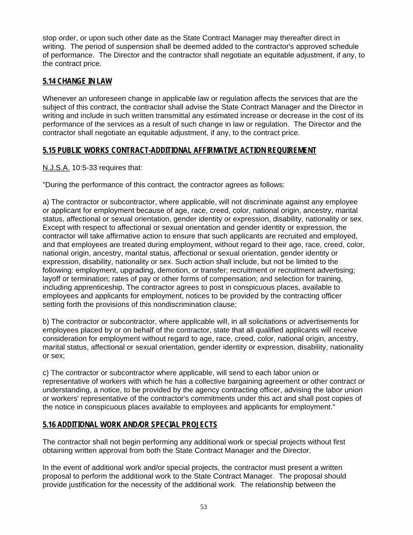
53
stop order, or upon such other date as the State Contract Manager may thereafter direct in writing. The period of suspension shall be deemed added to the contractor's approved schedule of performance. The Director and the contractor shall negotiate an equitable adjustment, if any, to the contract price. 5.14 CHANGE IN LAW Whenever an unforeseen change in applicable law or regulation affects the services that are the subject of this contract, the contractor shall advise the State Contract Manager and the Director in writing and include in such written transmittal any estimated increase or decrease in the cost of its performance of the services as a result of such change in law or regulation. The Director and the contractor shall negotiate an equitable adjustment, if any, to the contract price. 5.15 PUBLIC WORKS CONTRACT-ADDITIONAL AFFIRMATIVE ACTION REQUIREMENT N.J.S.A. 10:5-33 requires that: "During the performance of this contract, the contractor agrees as follows: a) The contractor or subcontractor, where applicable, will not discriminate against any employee or applicant for employment because of age, race, creed, color, national origin, ancestry, marital status, affectional or sexual orientation, gender identity or expression, disability, nationality or sex. Except with respect to affectional or sexual orientation and gender identity or expression, the contractor will take affirmative action to ensure that such applicants are recruited and employed, and that employees are treated during employment, without regard to their age, race, creed, color, national origin, ancestry, marital status, affectional or sexual orientation, gender identity or expression, disability, nationality or sex. Such action shall include, but not be limited to the following: employment, upgrading, demotion, or transfer; recruitment or recruitment advertising; layoff or termination; rates of pay or other forms of compensation; and selection for training, including apprenticeship. The contractor agrees to post in conspicuous places, available to employees and applicants for employment, notices to be provided by the contracting officer setting forth the provisions of this nondiscrimination clause; b) The contractor or subcontractor, where applicable will, in all solicitations or advertisements for employees placed by or on behalf of the contractor, state that all qualified applicants will receive consideration for employment without regard to age, race, creed, color, national origin, ancestry, marital status, affectional or sexual orientation, gender identity or expression, disability, nationality or sex; c) The contractor or subcontractor where applicable, will send to each labor union or representative of workers with which he has a collective bargaining agreement or other contract or understanding, a notice, to be provided by the agency contracting officer, advising the labor union or workers' representative of the contractor's commitments under this act and shall post copies of the notice in conspicuous places available to employees and applicants for employment." 5.16 ADDITIONAL WORK AND/OR SPECIAL PROJECTS The contractor shall not begin performing any additional work or special projects without first obtaining written approval from both the State Contract Manager and the Director. In the event of additional work and/or special projects, the contractor must present a written proposal to perform the additional work to the State Contract Manager. The proposal should provide justification for the necessity of the additional work. The relationship between the

54
additional work and the base contract work must be clearly established by the contractor in its proposal. The contractor’s written proposal must provide a detailed description of the work to be performed broken down by task and subtask. The proposal should also contain details on the level of effort, including hours, labor categories, etc., necessary to complete the additional work. The written proposal must detail the cost necessary to complete the additional work in a manner consistent with the contract. The written price schedule must be based upon the hourly rates, unit costs or other cost elements submitted by the contractor in the contractor’s original bid proposal submitted in response to this RFP. Whenever possible, the price schedule should be a firm, fixed cost to perform the required work. The firm fixed price should specifically reference and be tied directly to costs submitted by the contractor in its original bid proposal. A payment schedule, tied to successful completion of tasks and subtasks, must be included. Upon receipt and approval of the contractor’s written proposal, the State Contract Manager shall forward same to the Director for the Director’s written approval. Complete documentation from the Using Agency, confirming the need for the additional work, must be submitted. Documentation forwarded by the State Contract Manager to the Director must include all other required State approvals, such as those that may be required from the State of New Jersey’s Office of Management and Budget (OMB) and Office of Information and Technology (OIT). No additional work and/or special project may commence without the Director’s written approval. In the event the contractor proceeds with additional work and/or special projects without the Director’s written approval, it shall be at the contractor’s sole risk. The State shall be under no obligation to pay for work performed without the Director’s written approval. 5.17 FORM OF COMPENSATION AND PAYMENT This Section supplements Section 4.5 of the NJ Standard Terms and Conditions version 07/27/07, located on the Advertised Solicitation, Current Bid Opportunities webpage http://www.state.nj.us/treasury/purchase/bid/summary/09-R-20688.shtml. The contractor must submit official State invoice forms to the Using Agency with supporting documentation evidencing that work for which payment is sought has been satisfactorily completed. Invoices must reference the tasks or subtasks detailed in the Scope of Work section of the RFP and must be in strict accordance with the firm, fixed prices submitted for each task or subtask on the RFP pricing sheets. When applicable, invoices should reference the appropriate RFP price sheet line number from the contractor’s bid proposal. All invoices must be approved by the State Contract Manager before payment will be authorized. In addition, primary contractors must provide, on a monthly and cumulative basis, a breakdown in accordance with the budget submitted, of all monies paid to any small business subcontractor(s). This breakdown shall be sent to the Purchase Bureau Business Unit, Set-Aside Coordinator. Invoices must also be submitted for any special projects, additional work or other items properly authorized and satisfactorily completed under the contract. Invoices shall be submitted according to the payment schedule agreed upon when the work was authorized and approved. Payment can only be made for work when it has received all required written approvals and has been satisfactorily completed.
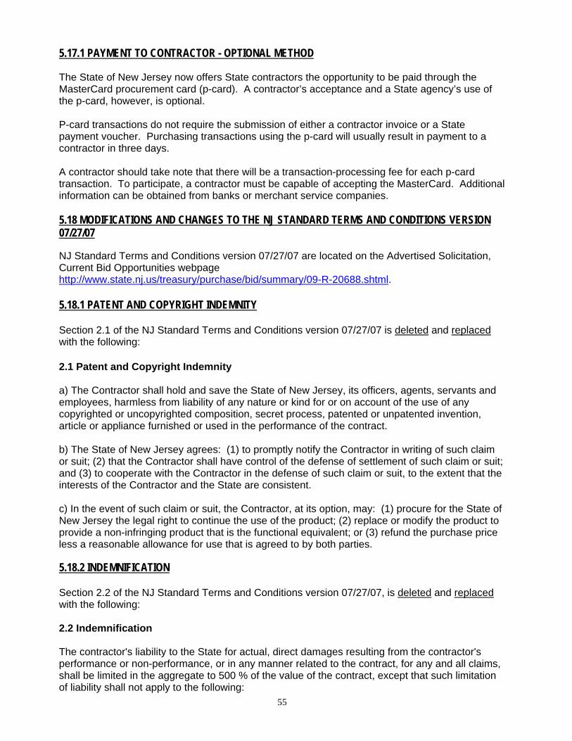
55
5.17.1 PAYMENT TO CONTRACTOR - OPTIONAL METHOD The State of New Jersey now offers State contractors the opportunity to be paid through the MasterCard procurement card (p-card). A contractor’s acceptance and a State agency’s use of the p-card, however, is optional. P-card transactions do not require the submission of either a contractor invoice or a State payment voucher. Purchasing transactions using the p-card will usually result in payment to a contractor in three days. A contractor should take note that there will be a transaction-processing fee for each p-card transaction. To participate, a contractor must be capable of accepting the MasterCard. Additional information can be obtained from banks or merchant service companies. 5.18 MODIFICATIONS AND CHANGES TO THE NJ STANDARD TERMS AND CONDITIONS VERSION 07/27/07
NJ Standard Terms and Conditions version 07/27/07 are located on the Advertised Solicitation, Current Bid Opportunities webpage http://www.state.nj.us/treasury/purchase/bid/summary/09-R-20688.shtml. 5.18.1 PATENT AND COPYRIGHT INDEMNITY Section 2.1 of the NJ Standard Terms and Conditions version 07/27/07 is deleted and replaced with the following: 2.1 Patent and Copyright Indemnity a) The Contractor shall hold and save the State of New Jersey, its officers, agents, servants and employees, harmless from liability of any nature or kind for or on account of the use of any copyrighted or uncopyrighted composition, secret process, patented or unpatented invention, article or appliance furnished or used in the performance of the contract. b) The State of New Jersey agrees: (1) to promptly notify the Contractor in writing of such claim or suit; (2) that the Contractor shall have control of the defense of settlement of such claim or suit; and (3) to cooperate with the Contractor in the defense of such claim or suit, to the extent that the interests of the Contractor and the State are consistent. c) In the event of such claim or suit, the Contractor, at its option, may: (1) procure for the State of New Jersey the legal right to continue the use of the product; (2) replace or modify the product to provide a non-infringing product that is the functional equivalent; or (3) refund the purchase price less a reasonable allowance for use that is agreed to by both parties.
5.18.2 INDEMNIFICATION Section 2.2 of the NJ Standard Terms and Conditions version 07/27/07, is deleted and replaced with the following: 2.2 Indemnification The contractor's liability to the State for actual, direct damages resulting from the contractor's performance or non-performance, or in any manner related to the contract, for any and all claims, shall be limited in the aggregate to 500 % of the value of the contract, except that such limitation of liability shall not apply to the following:
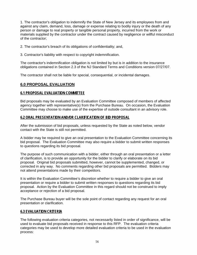
56
1. The contractor's obligation to indemnify the State of New Jersey and its employees from and against any claim, demand, loss, damage or expense relating to bodily injury or the death of any person or damage to real property or tangible personal property, incurred from the work or materials supplied by the contractor under the contract caused by negligence or willful misconduct of the contractor; 2. The contractor's breach of its obligations of confidentiality; and, 3. Contractor's liability with respect to copyright indemnification. The contractor's indemnification obligation is not limited by but is in addition to the insurance obligations contained in Section 2.3 of the NJ Standard Terms and Conditions version 07/27/07. The contractor shall not be liable for special, consequential, or incidental damages. 6.0 PROPOSAL EVALUATION 6.1 PROPOSAL EVALUATION COMMITTEE Bid proposals may be evaluated by an Evaluation Committee composed of members of affected agency together with representative(s) from the Purchase Bureau. On occasion, the Evaluation Committee may choose to make use of the expertise of outside consultant in an advisory role.
6.2 ORAL PRESENTATION AND/OR CLARIFICATION OF BID PROPOSAL After the submission of bid proposals, unless requested by the State as noted below, vendor contact with the State is still not permitted. A bidder may be required to give an oral presentation to the Evaluation Committee concerning its bid proposal. The Evaluation Committee may also require a bidder to submit written responses to questions regarding its bid proposal. The purpose of such communication with a bidder, either through an oral presentation or a letter of clarification, is to provide an opportunity for the bidder to clarify or elaborate on its bid proposal. Original bid proposals submitted, however, cannot be supplemented, changed, or corrected in any way. No comments regarding other bid proposals are permitted. Bidders may not attend presentations made by their competitors. It is within the Evaluation Committee’s discretion whether to require a bidder to give an oral presentation or require a bidder to submit written responses to questions regarding its bid proposal. Action by the Evaluation Committee in this regard should not be construed to imply acceptance or rejection of a bid proposal. The Purchase Bureau buyer will be the sole point of contact regarding any request for an oral presentation or clarification. 6.3 EVALUATION CRITERIA The following evaluation criteria categories, not necessarily listed in order of significance, will be used to evaluate bid proposals received in response to this RFP. The evaluation criteria categories may be used to develop more detailed evaluation criteria to be used in the evaluation process:
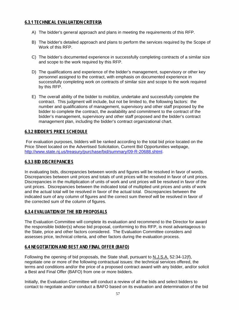
57
6.3.1 TECHNICAL EVALUATION CRITERIA
A) The bidder's general approach and plans in meeting the requirements of this RFP.
B) The bidder's detailed approach and plans to perform the services required by the Scope of Work of this RFP.
C) The bidder’s documented experience in successfully completing contracts of a similar size
and scope to the work required by this RFP.
D) The qualifications and experience of the bidder’s management, supervisory or other key personnel assigned to the contract, with emphasis on documented experience in successfully completing work on contracts of similar size and scope to the work required by this RFP.
E) The overall ability of the bidder to mobilize, undertake and successfully complete the
contract. This judgment will include, but not be limited to, the following factors: the number and qualifications of management, supervisory and other staff proposed by the bidder to complete the contract, the availability and commitment to the contract of the bidder’s management, supervisory and other staff proposed and the bidder’s contract management plan, including the bidder’s contract organizational chart.
6.3.2 BIDDER’S PRICE SCHEDULE For evaluation purposes, bidders will be ranked according to the total bid price located on the Price Sheet located on the Advertised Solicitation, Current Bid Opportunities webpage, http://www.state.nj.us/treasury/purchase/bid/summary/09-R-20688.shtml. 6.3.3 BID DISCREPANCIES In evaluating bids, discrepancies between words and figures will be resolved in favor of words. Discrepancies between unit prices and totals of unit prices will be resolved in favor of unit prices. Discrepancies in the multiplication of units of work and unit prices will be resolved in favor of the unit prices. Discrepancies between the indicated total of multiplied unit prices and units of work and the actual total will be resolved in favor of the actual total. Discrepancies between the indicated sum of any column of figures and the correct sum thereof will be resolved in favor of the corrected sum of the column of figures. 6.3.4 EVALUATION OF THE BID PROPOSALS The Evaluation Committee will complete its evaluation and recommend to the Director for award the responsible bidder(s) whose bid proposal, conforming to this RFP, is most advantageous to the State, price and other factors considered. The Evaluation Committee considers and assesses price, technical criteria, and other factors during the evaluation process. 6.4 NEGOTIATION AND BEST AND FINAL OFFER (BAFO) Following the opening of bid proposals, the State shall, pursuant to N.J.S.A. 52:34-12(f), negotiate one or more of the following contractual issues: the technical services offered, the terms and conditions and/or the price of a proposed contract award with any bidder, and/or solicit a Best and Final Offer (BAFO) from one or more bidders. Initially, the Evaluation Committee will conduct a review of all the bids and select bidders to contact to negotiate and/or conduct a BAFO based on its evaluation and determination of the bid
58
proposals that best satisfy the evaluation criteria and RFP requirements, and that are most advantageous to the State, price and other factors considered. The Committee may not contact all bidders to negotiate and/or to submit a BAFO. In response to the State's request to negotiate, bidders must continue to satisfy all mandatory RFP requirements but may improve upon their original technical proposal in any revised technical proposal. However, any revised technical proposal that does not continue to satisfy all mandatory requirements will be rejected as non-responsive and the original technical proposal will be used for any further evaluation purposes in accordance with the following procedure. In response to the State's request for a BAFO, bidders may submit a revised price proposal that is equal to or lower in price than their original submission, but must continue to satisfy all mandatory requirements. Any revised price proposal that is higher in price than the original will be rejected as non-responsive and the original bid will be used for any further evaluation purposes. After receipt of the results of the negotiation and/or the BAFO(s), the Evaluation Committee will complete its evaluation and recommend to the Director for award that responsible bidder(s) whose bid proposal, conforming to this RFP, is most advantageous to the State, price and other factors considered. All contacts, records of initial evaluations, any correspondence with bidders related to any request for negotiation or BAFO, any revised technical and/or price proposals, the Evaluation Committee Report and the Award Recommendation, will remain confidential until a Notice of Intent to Award a contract is issued. 7.0 CONTRACT AWARD 7.1 DOCUMENTS REQUIRED BEFORE CONTRACT AWARD 7.1.1 REQUIREMENTS OF N.J.S.A. 19:44A-20.13-25 (FORMERLY EXECUTIVE ORDER 134) In order to safeguard the integrity of State government procurement by imposing restrictions to insulate the negotiation and award of State contracts from political contributions that pose the risk of improper influence, purchase of access, or the appearance thereof, the Legislature enacted N.J.S.A. 19:44A-20.13 – 25 on March 22, 2005 the “Legislation”), retroactive to October 15, 2004, superseding the terms of Executive Order 134. Pursuant to the requirements of the Legislation, the terms and conditions set forth in this section are material terms of any contract resulting from this RFP: 7.1.1.1 DEFINITIONS For the purpose of this section, the following shall be defined as follows: a) Contribution – means a contribution reportable as a recipient under “The New Jersey Campaign Contributions and Expenditures Reporting Act.” P.L. 1973, c. 83 (C.19:44A-1 et seq.), and implementing regulations set forth at N.J.A.C. 19:25-7 and N.J.A.C. 19:25-10.1 et seq. Through December 31, 2004, contributions in excess of $400 during a reporting period were deemed "reportable" under these laws. As of January 1, 2005, that threshold was reduced to contributions in excess of $300. b) Business Entity – means any natural or legal person, business corporation, professional services corporation, Limited Liability Company, partnership, limited partnership, business trust,
59
association or any other legal commercial entity organized under the laws of New Jersey or any other state or foreign jurisdiction. The definition of a business entity includes (i)all principals who own or control more than 10 percent of the profits or assets of a business entity or 10 percent of the stock in the case of a business entity that is a corporation for profit, as appropriate; (ii)any subsidiaries directly or indirectly controlled by the business entity; (iii)any political organization organized under section 527 of the Internal Revenue Code that is directly or indirectly controlled by the business entity, other than a candidate committee, election fund, or political party committee; and (iv)if a business entity is a natural person, that person’s spouse or child, residing in the same household. 7.1.1.2 BREACH OF TERMS OF THE LEGISLATION It shall be a breach of the terms of the contract for the Business Entity to (i)make or solicit a contribution in violation of the Legislation, (ii)knowingly conceal or misrepresent a contribution given or received; (iii)make or solicit contributions through intermediaries for the purpose of concealing or misrepresenting the source of the contribution; (iv)make or solicit any contribution on the condition or with the agreement that it will be contributed to a campaign committee or any candidate of holder of the public office of Governor, or to any State or county party committee; (v)engage or employ a lobbyist or consultant with the intent or understanding that such lobbyist or consultant would make or solicit any contribution, which if made or solicited by the business entity itself, would subject that entity to the restrictions of the Legislation; (vi)fund contributions made by third parties, including consultants, attorneys, family members, and employees; (vii)engage in any exchange of contributions to circumvent the intent of the Legislation; or (viii)directly or indirectly through or by any other person or means, do any act which would subject that entity to the restrictions of the Legislation. 7.1.1.3 CERTIFICATION AND DISCLOSURE REQUIREMENTS a) The State shall not enter into a contract to procure from any Business Entity services or any material, supplies or equipment, or to acquire, sell or lease any land or building, where the value of the transaction exceeds $17,500, if that Business Entity has solicited or made any contribution of money, or pledge of contribution, including in-kind contributions to a candidate committee and/or election fund of any candidate for or holder of the public office of Governor, or to any State or county political party committee during certain specified time periods b) Prior to awarding any contract or agreement to any Business Entity, the Business Entity proposed as the intended awardee of the contract shall submit the Certification and Disclosure form, certifying that no contributions prohibited by the Legislation have been made by the Business Entity and reporting all contributions the Business Entity made during the preceding four years to any political organization organized under 26 U.S.C.527 of the Internal Revenue Code that also meets the definition of a “continuing political committee” within the mean of N.J.S.A. 19:44A-3(n) and N.J.A.C. 19:25-1.7. The required form and instructions, available for review on the Purchase Bureau website at http://www.state.nj.us/treasury/purchase/forms.htm#eo134, shall be provided to the intended awardee for completion and submission to the Purchase Bureau with the Notice of Intent to Award. Upon receipt of a Notice of Intent to Award a Contract, the intended awardee shall submit to the Division, in care of the Purchase Bureau Buyer, the Certification and Disclosure(s) within five (5) business days of the State’s request. Failure to submit the required forms will preclude award of a contract under this RFP, as well as future contract opportunities. c) Further, the Contractor is required, on a continuing basis, to report any contributions it makes during the term of the contract, and any extension(s) thereof, at the time any such contribution is made. The required form and instructions, available for review on the Purchase Bureau website
60
at http://www.state.nj.us/treasury/purchase/forms.htm#eo134, shall be provided to the intended awardee with the Notice of Intent to Award. 7.1.1.4 STATE TREASURER REVIEW The State Treasurer or his designee shall review the Disclosures submitted pursuant to this section, as well as any other pertinent information concerning the contributions or reports thereof by the intended awardee, prior to award, or during the term of the contract, by the contractor. If the State Treasurer determines that any contribution or action by the contractor constitutes a breach of contract that poses a conflict of interest in the awarding of the contract under this solicitation, the State Treasurer shall disqualify the Business Entity from award of such contract. 7.1.1.5 ADDITIONAL DISCLOSURE REQUIREMENT OF P.L. 2005, C. 271 Contractor is advised of its responsibility to file an annual disclosure statement on political contributions with the New Jersey Election Law Enforcement Commission (ELEC), pursuant to P.L. 2005, c. 271, section 3 if the contractor receives contracts in excess of $50,000 from a public entity in a calendar year. It is the contractor’s responsibility to determine if filing is necessary. Failure to so file can result in the imposition of financial penalties by ELEC. Additional information about this requirement is available from ELEC at 888-313-3532 or at www.elec.state.nj.us. 7.1.2 SOURCE DISCLOSURE REQUIREMENTS 7.1.2.1 REQUIREMENTS OF N.J.S.A. 52:34-13.2 Under the referenced statute, effective August 3, 2005, all contracts primarily for services awarded by the Director shall be performed within the United States, except when the Director certifies in writing a finding that a required service cannot be provided by a contractor or subcontractor within the United States and the certification is approved by the State Treasurer. 7.1.2.2 SOURCE DISCLOSURE REQUIREMENTS Pursuant to the statutory requirements, the intended awardee of a contract primarily for services with the State of New Jersey must disclose the location by country where services under the contract, including subcontracted services, will be performed. The Source Disclosure Certification form is located on the Advertised Solicitation, Current Bid Opportunities webpage http://www.state.nj.us/treasury/purchase/bid/summary/09-R-20688.shtml. FAILURE TO SUBMIT SOURCING INFORMATION WHEN REQUESTED BY THE STATE SHALL PRECLUDE AWARD OF A CONTRACT TO THE BIDDER. If any of the services cannot be performed within the United States, the bidder shall state with specificity the reasons why the services cannot be so performed. The Director shall determine whether sufficient justification has been provided by the bidder to form the basis of his certification that the services cannot be performed in the United States and whether to seek the approval of the Treasurer. 7.1.2.3 BREACH OF CONTRACT OF EXECUTIVE ORDER 129 A SHIFT TO PROVISION OF SERVICES OUTSIDE THE UNITED STATES DURING THE TERM OF THE CONTRACT SHALL BE DEEMED A BREACH OF CONTRACT.

61
If, during the term of the contract, the contractor or subcontractor, who had on contract award declared that services would be performed in the United States, proceeds to shift the performance of any of the services outside the United States, the contractor shall be deemed to be in breach of its contract, which contract shall be subject to termination for cause pursuant to Section 3.5b.1 of the Standard Terms and Conditions version 07/27/07 of the RFP, unless previously approved by the Director and the Treasurer. 7.2 FINAL CONTRACT AWARD Contract award shall be made with reasonable promptness by written notice to that responsible bidder, whose bid proposal, conforming to this RFP, is most advantageous to the State, price, and other factors considered. Any or all bid proposals may be rejected when the State Treasurer or the Director determines that it is in the public interest to do so. 7.3 INSURANCE CERTIFICATES The contractor shall provide the State with current certificates of insurance for all coverages required by the terms of this contract, naming the State as an Additional Insured. 7.4 PERFORMANCE BOND This section supplements Section 3.3b of the NJ Standard Terms and Conditions version 07/27/07, located on the Advertised Solicitation, Current Bid Opportunities webpage http://www.state.nj.us/treasury/purchase/bid/summary/09-R-20688.shtml. A performance bond is required. The amount of the performance bond is noted on the RFP signatory page located on the Advertised Solicitation, Current Bid Opportunities webpage http://www.state.nj.us/treasury/purchase/bid/summary/09-R-20688.shtml. The contractor must provide the performance bond within thirty (30) days of the effective date of the contract award. The performance bond must remain in full force and effect for the term of the contract and any extension thereof. Within thirty (30) days of the anniversary of the contract effective date, the contractor shall provide proof to the Director that the performance bond in the required amount is in effect. Failure to provide such proof may result in the suspension of payment to the contractor until such time the contractor complies with this requirement. Although the performance bond is required for the full term of the contract, the Director recognizes that the industry practice of sureties is to issue a one year performance bond for goods and services contracts. Thus, the contractor is required to submit a one year performance bond for the amount required under the contract and, on each succeeding anniversary date of the contract, provide a continuation or renewal certificate to evidence that the bond is in effect for the next year of the contract. This procedure will remain in place for each year of the contract thereafter until the termination of the contract. Failure to provide such proof on the anniversary date of the contract shall result in suspension of the contract, and possibly, termination of the contract. For performance bonds based on a percentage of the total estimated contract price, the performance bond requirement is calculated as follows. For the first year of the contract, the performance bond percentage on the RFP signatory page is applied to the estimated total contract amount for the full term of the contract. On each anniversary of the effective date of the contract, the amount of the required performance bond, unless otherwise noted, is calculated by applying the established RFP performance bond percentage to the outstanding balance of the estimated amount of the contract price to be paid to the contractor.
62
In the event that the contract price is increased by amendment to the contract, the contractor may be required to provide, within thirty (30) days of the effective date of the amendment, performance bond coverage for the increase in contract price. The required increase in the performance bond amount is calculated by applying the established bond percentage set forth on RFP signatory page to the increase in contract price. Failure to provide such proof to the Director of this required coverage may result in the suspension of payment to the contractor until such time the contractor complies with this requirement. 8.0 CONTRACT ADMINISTRATION 8.1 CONTRACT MANAGER The State Contract Manager is the State employee responsible for the overall management and administration of the contract. The State Contract Manager for this project will be identified at the time of execution of contract. At that time, the contractor will be provided with the State Contract Manager’s name, department, division, agency, address, telephone number, fax phone number, and email address. 8.1.1 STATE CONTRACT MANAGER RESPONSIBILITIES For an agency contract where only one State office uses the contract, the State Contract Manager will be responsible for engaging the contractor, assuring that Purchase Orders are issued to the contractor, directing the contractor to perform the work of the contract, approving the deliverables and approving payment vouchers. The State Contract Manager is the person that the contractor will contact after the contract is executed for answers to any questions and concerns about any aspect of the contract. The State Contract Manager is responsible for coordinating the use and resolving minor disputes between the contractor and any component part of the State Contract Manager's Department. If the contract has multiple users, then the State Contract Manager shall be the central coordinator of the use of the contract for all Using Agencies, while other State employees engage and pay the contractor. All persons and agencies that use the contract must notify and coordinate the use of the contract with the State Contract Manager. 8.1.2 COORDINATION WITH THE STATE CONTRACT MANAGER Any contract user that is unable to resolve disputes with a contractor shall refer those disputes to the State Contract Manager for resolution. Any questions related to performance of the work of the contract by contract users shall be directed to the State Contract Manager. The contractor may contact the State Contract Manager if the contractor can not resolve a dispute with contract users.