Embed Size (px)
Citation preview
REV 310 567E1
For more information see wwwcranecamscom
CRANE CAMS Daytona Beach FL 32117wwwcranecamscom Phone 866-388-5120 Fax 608-627-0480
Installation Instructions ndash 567ERoller Camshaft Installation
READ CAREFULLY AND COMPLETELY BEFORE INSTALLATIONPrior to installation immerse lifters in a premium petroleum based oil with a viscosity rating of not less than 10w 40 but do not attempt to pump up hydraulic lifters This hinders the adjustment of proper preload settings Proper lifter pump up will occur during the initial start up after approximately 40 seconds Complete lifter bleeding may take up to fifteen minutes
CRANE ROLLER CAMSHAFT INSTALLATION INSTRUCTIONSThe pictures shown in these instructions are for a small block Chevrolet Check your engine manual for timing mark alignment for other engines
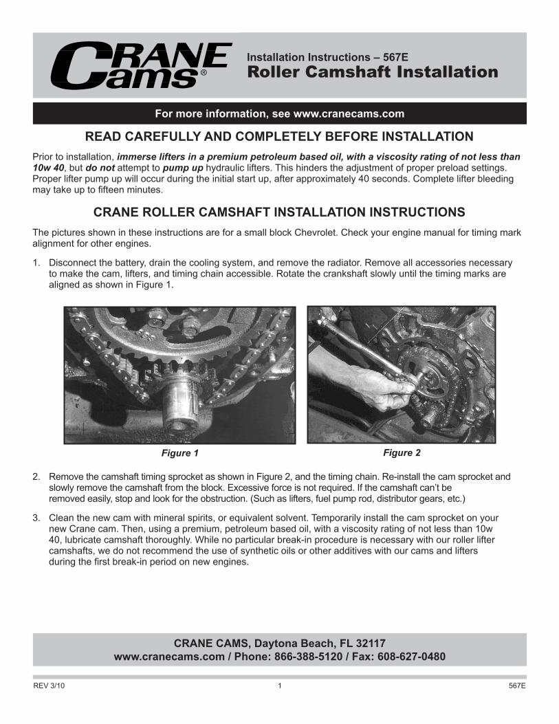
1 Disconnect the battery drain the cooling system and remove the radiator Remove all accessories necessary to make the cam lifters and timing chain accessible Rotate the crankshaft slowly until the timing marks are aligned as shown in Figure 1
2 Remove the camshaft timing sprocket as shown in Figure 2 and the timing chain Re-install the cam sprocket and slowly remove the camshaft from the block Excessive force is not required If the camshaft canrsquot be removed easily stop and look for the obstruction (Such as lifters fuel pump rod distributor gears etc)
3 Clean the new cam with mineral spirits or equivalent solvent Temporarily install the cam sprocket on your new Crane cam Then using a premium petroleum based oil with a viscosity rating of not less than 10w 40 lubricate camshaft thoroughly While no particular break-in procedure is necessary with our roller lifter camshafts we do not recommend the use of synthetic oils or other additives with our cams and lifters during the first break-in period on new engines
Figure 1 Figure 2
REV 310 567E2
4 Carefully slide your cam into the block Be careful not to damage cam bearings (Figure 3)
5 Remove the cam sprocket install a new Crane chain and bolt the assembly in place Check the timing mark alignment (Figure 4) or your engine manual Tighten the cam sprocket retaining bolts to correct torque specifications(Figure 5) This is very important as most cam damage is caused by the cam gear coming loose due to improperly torqued bolts or worn keys and keyways If the gear loosens the cam will slide back into the block causing the lifters to hit the adjacent lobes and bearing journals
Thread locking compound should be applied to the threads of all camshaft timing gear bolts Be sure to apply proper torque to the bolts as well A camshaft bolt locking plate part number 99168-1 is recommended for Chevrolet 262-400 and 396-454 cubic inch engines (Figure 6)
Figure 3
Figure 6
Figure 4 Figure 5
REV 310 567E3
Several cams require a plate that bolts to the block with a spacer between the cam gear and the front cambearing journal Some replacement gears have the spacer made on the gear If so make sure the original spacer is not used To check gear alignment put a straightedge across the timing gears from top to bottom To verify that you have the correct spacer to cam gear combination check that the camshaft end play is 004rdquo to 008rdquo (This procedure is for engines with cam retaining plates only)
Note Many 1972 and later Ford-Mercury V-8 engines are originally equipped with a retarded crankshaft sprocket This may cause idling and performance problems when installing aftermarket camshafts Eliminate this problem by installing a pre-1972 crankshaft sprocket (the non-retarded sprocket will have the alignment dot and keyway slot directly in line with each other) or by degreeing in your camshaft or with appropriate Crane timing chain and gear set
6 If cylinder head machining capabilities are not available or desired and stock springs and retainers are used make certain spring travel from assembled height to coil bind is a minimum of 060rdquo more than the gross lift of the cam Check with your Crane dealer for available Valve Spring and Retainer Kits that use stock diameter springs and require no head machining
7 As a general rule any cam with the same or less lift than any of our milder series cams for any given engine should have a safe amount of piston to valve clearance if the engine piston cylinder head combination is stock When using cams with higher lift or engines with internal engine modifications to pistons andor cylinder heads to increase compression piston to valve clearance must be checked Check with modeling clay when assembling the engine Minimum clearance is 080rdquo intake and 100rdquo exhaust
8 On engines with separate adjustable rocker arms such as small block Chevrolet we recommend installing the pushrods and rocker arms on one cylinder at a time and adjusting the valves on that particular cylinder Do not tighten the adjusting nut down before adjusting the valves If the adjustment is too tight this will cause the valve to hit the piston when you turn the engine over resulting in bent valves bent or broken pushrods rocker arm studs to be pulled out of the head and premature cam wear On engines with shaft mounted adjustable rocker arms back off all adjusters all the way before installing the assembly
Make sure the pushrod is in the tappet and in the rocker arm seat when making valve adjustments
For hydraulic lifter camshaft valve adjustment turn the engine in the normal direction of rotation until the exhaust lifter on the cylinder that yoursquore adjusting starts to move up then adjust the intake valve on that cylinder to zero lash with no preload then 12 to 1 full turn more Turn the engine over again until the intake lifter has come to full lift and then is almost all the way back down Now set the exhaust valve to zero lash then 12 to 1 full turn more Continue the above procedure for each cylinder until all valves are adjusted the same
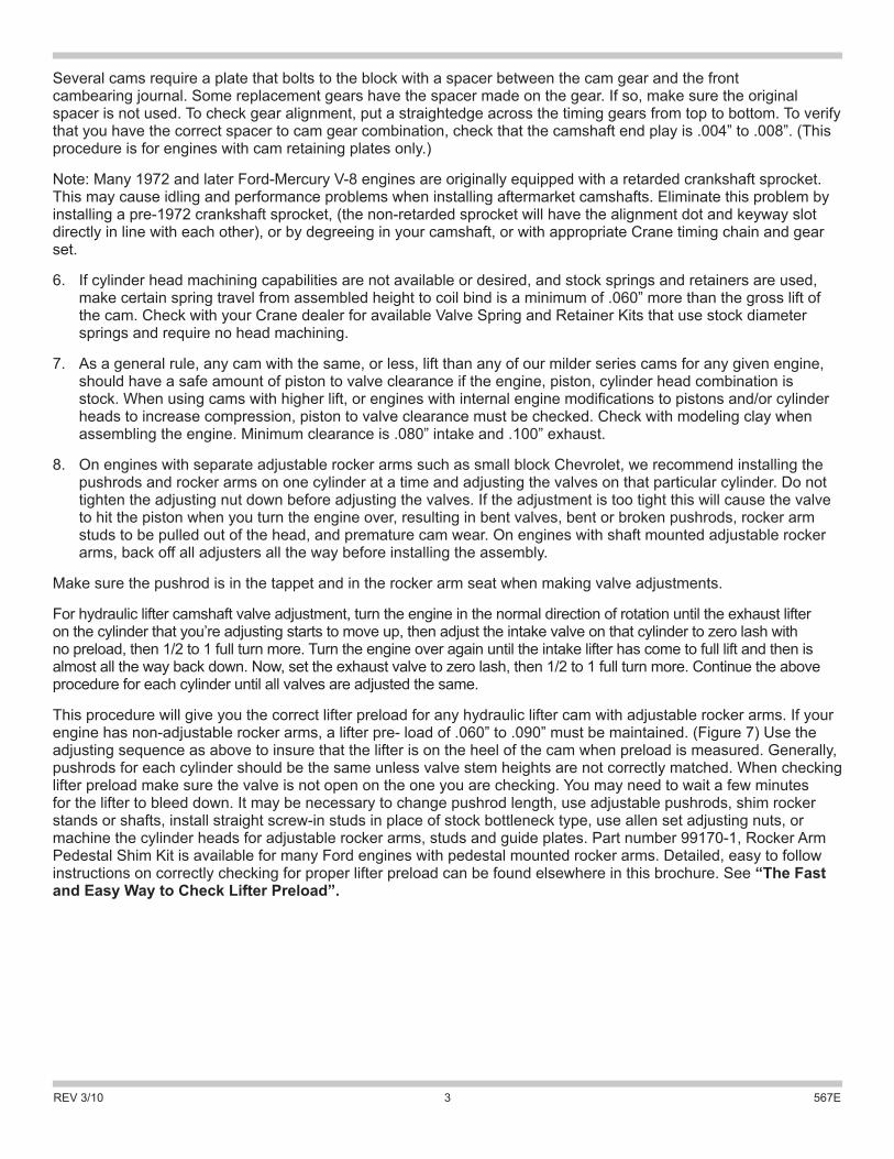
This procedure will give you the correct lifter preload for any hydraulic lifter cam with adjustable rocker arms If your engine has non-adjustable rocker arms a lifter pre- load of 060rdquo to 090rdquo must be maintained (Figure 7) Use the adjusting sequence as above to insure that the lifter is on the heel of the cam when preload is measured Generally pushrods for each cylinder should be the same unless valve stem heights are not correctly matched When checking lifter preload make sure the valve is not open on the one you are checking You may need to wait a few minutes for the lifter to bleed down It may be necessary to change pushrod length use adjustable pushrods shim rocker stands or shafts install straight screw-in studs in place of stock bottleneck type use allen set adjusting nuts or machine the cylinder heads for adjustable rocker arms studs and guide plates Part number 99170-1 Rocker Arm Pedestal Shim Kit is available for many Ford engines with pedestal mounted rocker arms Detailed easy to follow instructions on correctly checking for proper lifter preload can be found elsewhere in this brochure See ldquoThe Fast and Easy Way to Check Lifter Preloadrdquo
REV 310 567E4
If the adjustment procedures are followed correctly for hydraulic lifter cams no further adjustment is necessary for the life of the cam
The same basic adjustment procedure should be used for mechanical lifter cams Instead of lifter preload you must use the clearance specs on the cam card for your cam Mechanical lifter cams require a second adjustment after break-in then periodically at tune-up time for the life of the cam
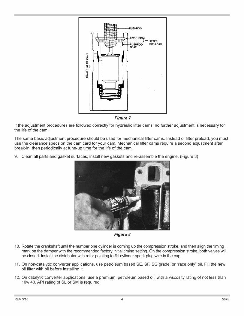
9 Clean all parts and gasket surfaces install new gaskets and re-assemble the engine (Figure 8)
10 Rotate the crankshaft until the number one cylinder is coming up the compression stroke and then align the timing mark on the damper with the recommended factory initial timing setting On the compression stroke both valves will be closed Install the distributor with rotor pointing to 1 cylinder spark plug wire in the cap
11 On non-catalytic converter applications use petroleum based SE SF SG grade or ldquorace onlyrdquo oil Fill the new oil filter with oil before installing it
12 On catalytic converter applications use a premium petroleum based oil with a viscosity rating of not less than 10w 40 API rating of SL or SM is required
Figure 7
Figure 8
REV 310 567E5
13 After the first hour or 100 miles of operation change the oil and filter and re-adjust the valves (if mechanical lifters) Adjust them while the engine is warm Some aids to help set lifter preload on nonadjustable rocker arm equipped engines are part number 99170-1 Rocker Arm Pedestal Shim Kit for Ford engines with pedestal mounted rocker arms Part number 99179-1 Rocker Arm Bridge Shim Kit is for Oldsmobile and some AMC V-8 and 6 cylinder engines with pivot bridge mounted rocker arms If you donrsquot understand these instructions please feel free to contact one of our Technical Consultants
THE FAST AND EASY WAY TO CHECK HYDRAULIC LIFTER PRE-LOADOne of the most important steps in hydraulic camshaft installation is checking the lifter preload This is the distance that the pushrod has extended into the lifter and depressed the pushrod seat from its retaining ring Accurately checking that this amount is correct (usually about a minimum of 060rdquo to a maximum of 090rdquo) is critical to engine operation and life of the cam lobes lifters and the enginersquos valve train itself If your engine has too little or no lifter preload the valve train will be very noisy when the engine is running If your engine has too much lifter preload it may idle roughly have low manifold vacuum and poor low-end performance and may stall when put into gear
The most accurate method of checking lifter preload is by use of a dial indicator but if you donrsquot have a dial indicator or donrsquot know how to use one therersquos an easy way that will work just as well Follow the instructions in your repair manual and torque all the bolts in their proper sequence Yoursquoll be ready to check lifter preload when you reach the step where yoursquore ready to adjust the valve lash
First allow a couple of minutes for the lifter to bleed-down after you have placed some preload on it This bleed-down period must be allowed to remove any of the oil that the lifter may have inside
VALVE TIMING MARKSThe valve timing marks shown are for camshaft installation use only and are not to be used for installing the distributor See step 10 for distributor installation
Many new lifters (you must use new lifters with any new cam installation) come with some amount of oil in them and you should allow one or two minutes for the bleed-down to occur
Using the valve cover gasket surface of the cylinder head as a guide lay a marking implement (metal scribe etc) flat on the reference guide Yoursquoll be making two marks so be sure your guide is flat and easily accessible Now scribe a line on the pushrod Next unbolt the rocker assembly and loosen the bolts so that the pushrod will stand free in the pushrod seat of the lifter Yoursquoll also note that the pushrod seat in the lifter will be forced up against the snap ring in the top of the lifter by the plunger spring in the lifter
Now scribe another mark on the pushrod Yoursquoll now have two marks on the pushrod The difference between the two marks is the amount of travel that the pushrod made into the lifter or the lifter preload
You should maintain a minimum of 060rdquo to a maximum of 090rdquo lifter preload In most installations yoursquoll normally find that you should have either the correct amount of preload or too much pre-load You can correct excessive lifter preload by shimming up a bridge-mount assembly by using Crane Camsrsquo 99179-1 Rocker Arm Shim Kit
Should you find that you have too little lifter preload or you have free-play between the rocker arm and pushrod you can also remedy this problem Simply measure the amount of free-play between rocker arm and pushrod and then add 060rdquo to this figure This will allow you to buy new Crane pushrods in ldquolonger than stockrdquo length or the stock length plus that amount yoursquove measured out Donrsquot forget to add the 060rdquo extra to allow the extra length needed to finally get the amount of preload that you were after in the first place We can make pushrods to any length but your measurements must be accurate so check your measurements several times to be sure
Normally yoursquoll only need to check two pushrods per cylinder head one each intake and exhaust However if the valve stem heights of all the valves in the head are uneven (measure from the spring seat to top of the valve) or different from factory specs (found in your manual) then it will be necessary to check lifter preload on each valve
REV 310 567E6
If yoursquore having a valve job done on your head(s) you can ask the machinist to check valve stem height for you This is actually a normal part of a properly done performance job but you might want to ask anyway The end result will allow you to lay a straightedge across all the valve stems on the assembled head and have valve stem height check the same across the stems
On other engines which have individual studs shoulder bolts or pedestals (such as the 151 cuin Pontiac 4 cylinder) it is still relatively easy to check lifter preload quick and easy For those engines that have bottleneck type studs we have special adjusting nuts that simplify the preload checking process This type of stud has a shoulder that is larger than the thread and the adjustment nut is tightened down to the shoulder thus eliminating any adjustment Special adjusting nuts are tubular in design with an allen head set screws in the top These nuts are also counterbored at the bottom so that they actually fit over the shoulder part of the stud
These special adjusting nuts allow you to achieve the proper lifter preload as previously outlined Tighten the adjusting nut down until you reach zero lash (no preload and no lash) then tighten it 12 to 1 turn more Hold the nut with an end wrench and tighten the allen head set screw tight against the top of the stud Continue this process until all of the valves have been adjusted
On engines with pedestal or shoulder bolt mounted rocker arms you can use shims under the pedestal or shoulder to reduce the preload If preload is too little or therersquos none at all yoursquoll need to have longer than stock pushrods made Use the same procedure outlined earlier to determine lifter preload and the amount longer your pushrods must be
On engines that have individually mounted rocker arms you should be able to achieve correct lifter preload by first tightening the adjusting nut or bolt down to zero lash Now torque into place the adjusting nut or bolt by tightening 34 to 1 full turn of torque wrench rotation This should place the pushrod at the correct lifter preload point If for some reason you cannot achieve the correct lifter preload (060rdquo to 090rdquo) with 34 to 1 full turn tighter then yoursquoll have to follow the instructions outlined earlier and use the appropriate shim kit or longer than stock pushrods
If you do not understand the previously mentioned steps or you have additional problems Stop before you make a mistake that will damage your new cam or valve train and call one of our Technical Consultants
TROUBLESHOOTING GUIDE
Adjust valve lash properlyAll engines have a means for changing their valve lash Be sure and follow the instructions included with the cam lifters or rocker arms Take the extra time required to check the items mentioned before you fire up the engine
Check for rocker arm interferenceInstalling a Crane performance camshaft usually means that you are increasing the maximum valve lift over that the stock camshaft On engines which have stud mounted rocker arms be sure and check the rocker arm slot that allows the rocker to pivot at maximum lift Be sure that there is some slight amount (060rdquo) of additional travel left in this slot when the valve is at maximum lift Be sure that the rocker arm contacts only the valve tip and not the valve spring or valve spring retainer
Check valve-to-piston clearanceMany times inexperienced or first time camshaft installers forget to check the engine1048577s valve-to-piston clearanceand end up by bending some or all of the engine1048577s valves when they strike the piston This is especially critical onan engine with domed pistons or where the camshaft being installed has more duration andor maximum valve lift than that of the previous cam Check this clearance before you fire up the engine Several ways can be used the easiest being to use modeling clay placed atop the valve area of a piston and then bolting the cylinder head in place and torquing it to specs Adjust the valves (donrsquot forget to use the head gasket for an accurate clearance check) then rotate the engine by hand several times Remove the head(s) and carefully peel off the clay and measure it with a micrometer Allow a minimum clearance of 080rdquo intake and 100rdquo exhaust
REV 310 567E7
Bent pushrods means mechanical interferenceIf you bend one two or several pushrods for no apparent reason then you are experiencing some form of definite mechanical interference in the enginersquos valve train Check for rocker arm to stud interference Valve spring coil binding interference between the retainer and the valve seal or retainer and valve guide Also high RPM might be showing valve-to-piston clearance problems that are causing your valves to strike the pistons and then bending the pushrods If this occurs and you suspect valve-to-piston clearance problems itrsquos a good idea to also check for bent or leaking valves and possible piston damage
Never advance or retard your cam timing without first taking the time to ldquodegree inrdquo the cam-shaft in the engineA cam change that doesnrsquot seem to have enough low end power might be an indication Frequently retarded cam timing is due to factory retarded timing gears Always degree-in the cam before you make any timing changes
Be sure and properly lube the camMany cams are ruined in the first couple of minutes of their life when they are installed dry or improperly lubricated Be sure and follow the instructions included with the camshaft or correct pre-lubrication of the cam and lifters before you fire up the engine
Follow cam break-in instructions ndash especially with regards to oil and filter replacementDirty oil and clogged old oil filters mean abrasives in the oiling system and wear for the camshaft lifters and all other engine components as well Spend a couple of extra dollars and buy high quality oil and filters and above all change both frequently This will add life to not only cam and lifters but the entire engine assembly as well
Breaking rocker arm pushrod seatsWe have found this to be a somewhat common problem especially when an engine has several thousand miles of usage on the rockers This usually occurs when a cam is installed that has a higher lift than the cam previously used The additional amount of travel required of the rocker arm tends to relocate the load generated by the valve train and concentrates it partially in the already worn area of the rocker arm pushrod seat and partially in the area not yet worn The result is a concentration of this loading in an area of thinner metal and breaking through or punching out of the pushrod seat often occurs The cure is to install new stock type steel rocker arms or a set of Crane aluminum rockers

REV 310 567E2
4 Carefully slide your cam into the block Be careful not to damage cam bearings (Figure 3)
5 Remove the cam sprocket install a new Crane chain and bolt the assembly in place Check the timing mark alignment (Figure 4) or your engine manual Tighten the cam sprocket retaining bolts to correct torque specifications(Figure 5) This is very important as most cam damage is caused by the cam gear coming loose due to improperly torqued bolts or worn keys and keyways If the gear loosens the cam will slide back into the block causing the lifters to hit the adjacent lobes and bearing journals
Thread locking compound should be applied to the threads of all camshaft timing gear bolts Be sure to apply proper torque to the bolts as well A camshaft bolt locking plate part number 99168-1 is recommended for Chevrolet 262-400 and 396-454 cubic inch engines (Figure 6)
Figure 3
Figure 6
Figure 4 Figure 5
REV 310 567E3
Several cams require a plate that bolts to the block with a spacer between the cam gear and the front cambearing journal Some replacement gears have the spacer made on the gear If so make sure the original spacer is not used To check gear alignment put a straightedge across the timing gears from top to bottom To verify that you have the correct spacer to cam gear combination check that the camshaft end play is 004rdquo to 008rdquo (This procedure is for engines with cam retaining plates only)
Note Many 1972 and later Ford-Mercury V-8 engines are originally equipped with a retarded crankshaft sprocket This may cause idling and performance problems when installing aftermarket camshafts Eliminate this problem by installing a pre-1972 crankshaft sprocket (the non-retarded sprocket will have the alignment dot and keyway slot directly in line with each other) or by degreeing in your camshaft or with appropriate Crane timing chain and gear set
6 If cylinder head machining capabilities are not available or desired and stock springs and retainers are used make certain spring travel from assembled height to coil bind is a minimum of 060rdquo more than the gross lift of the cam Check with your Crane dealer for available Valve Spring and Retainer Kits that use stock diameter springs and require no head machining
7 As a general rule any cam with the same or less lift than any of our milder series cams for any given engine should have a safe amount of piston to valve clearance if the engine piston cylinder head combination is stock When using cams with higher lift or engines with internal engine modifications to pistons andor cylinder heads to increase compression piston to valve clearance must be checked Check with modeling clay when assembling the engine Minimum clearance is 080rdquo intake and 100rdquo exhaust
8 On engines with separate adjustable rocker arms such as small block Chevrolet we recommend installing the pushrods and rocker arms on one cylinder at a time and adjusting the valves on that particular cylinder Do not tighten the adjusting nut down before adjusting the valves If the adjustment is too tight this will cause the valve to hit the piston when you turn the engine over resulting in bent valves bent or broken pushrods rocker arm studs to be pulled out of the head and premature cam wear On engines with shaft mounted adjustable rocker arms back off all adjusters all the way before installing the assembly
Make sure the pushrod is in the tappet and in the rocker arm seat when making valve adjustments
For hydraulic lifter camshaft valve adjustment turn the engine in the normal direction of rotation until the exhaust lifter on the cylinder that yoursquore adjusting starts to move up then adjust the intake valve on that cylinder to zero lash with no preload then 12 to 1 full turn more Turn the engine over again until the intake lifter has come to full lift and then is almost all the way back down Now set the exhaust valve to zero lash then 12 to 1 full turn more Continue the above procedure for each cylinder until all valves are adjusted the same
This procedure will give you the correct lifter preload for any hydraulic lifter cam with adjustable rocker arms If your engine has non-adjustable rocker arms a lifter pre- load of 060rdquo to 090rdquo must be maintained (Figure 7) Use the adjusting sequence as above to insure that the lifter is on the heel of the cam when preload is measured Generally pushrods for each cylinder should be the same unless valve stem heights are not correctly matched When checking lifter preload make sure the valve is not open on the one you are checking You may need to wait a few minutes for the lifter to bleed down It may be necessary to change pushrod length use adjustable pushrods shim rocker stands or shafts install straight screw-in studs in place of stock bottleneck type use allen set adjusting nuts or machine the cylinder heads for adjustable rocker arms studs and guide plates Part number 99170-1 Rocker Arm Pedestal Shim Kit is available for many Ford engines with pedestal mounted rocker arms Detailed easy to follow instructions on correctly checking for proper lifter preload can be found elsewhere in this brochure See ldquoThe Fast and Easy Way to Check Lifter Preloadrdquo
REV 310 567E4
If the adjustment procedures are followed correctly for hydraulic lifter cams no further adjustment is necessary for the life of the cam
The same basic adjustment procedure should be used for mechanical lifter cams Instead of lifter preload you must use the clearance specs on the cam card for your cam Mechanical lifter cams require a second adjustment after break-in then periodically at tune-up time for the life of the cam
9 Clean all parts and gasket surfaces install new gaskets and re-assemble the engine (Figure 8)
10 Rotate the crankshaft until the number one cylinder is coming up the compression stroke and then align the timing mark on the damper with the recommended factory initial timing setting On the compression stroke both valves will be closed Install the distributor with rotor pointing to 1 cylinder spark plug wire in the cap
11 On non-catalytic converter applications use petroleum based SE SF SG grade or ldquorace onlyrdquo oil Fill the new oil filter with oil before installing it
12 On catalytic converter applications use a premium petroleum based oil with a viscosity rating of not less than 10w 40 API rating of SL or SM is required
Figure 7
Figure 8
REV 310 567E5
13 After the first hour or 100 miles of operation change the oil and filter and re-adjust the valves (if mechanical lifters) Adjust them while the engine is warm Some aids to help set lifter preload on nonadjustable rocker arm equipped engines are part number 99170-1 Rocker Arm Pedestal Shim Kit for Ford engines with pedestal mounted rocker arms Part number 99179-1 Rocker Arm Bridge Shim Kit is for Oldsmobile and some AMC V-8 and 6 cylinder engines with pivot bridge mounted rocker arms If you donrsquot understand these instructions please feel free to contact one of our Technical Consultants
THE FAST AND EASY WAY TO CHECK HYDRAULIC LIFTER PRE-LOADOne of the most important steps in hydraulic camshaft installation is checking the lifter preload This is the distance that the pushrod has extended into the lifter and depressed the pushrod seat from its retaining ring Accurately checking that this amount is correct (usually about a minimum of 060rdquo to a maximum of 090rdquo) is critical to engine operation and life of the cam lobes lifters and the enginersquos valve train itself If your engine has too little or no lifter preload the valve train will be very noisy when the engine is running If your engine has too much lifter preload it may idle roughly have low manifold vacuum and poor low-end performance and may stall when put into gear
The most accurate method of checking lifter preload is by use of a dial indicator but if you donrsquot have a dial indicator or donrsquot know how to use one therersquos an easy way that will work just as well Follow the instructions in your repair manual and torque all the bolts in their proper sequence Yoursquoll be ready to check lifter preload when you reach the step where yoursquore ready to adjust the valve lash
First allow a couple of minutes for the lifter to bleed-down after you have placed some preload on it This bleed-down period must be allowed to remove any of the oil that the lifter may have inside
VALVE TIMING MARKSThe valve timing marks shown are for camshaft installation use only and are not to be used for installing the distributor See step 10 for distributor installation
Many new lifters (you must use new lifters with any new cam installation) come with some amount of oil in them and you should allow one or two minutes for the bleed-down to occur
Using the valve cover gasket surface of the cylinder head as a guide lay a marking implement (metal scribe etc) flat on the reference guide Yoursquoll be making two marks so be sure your guide is flat and easily accessible Now scribe a line on the pushrod Next unbolt the rocker assembly and loosen the bolts so that the pushrod will stand free in the pushrod seat of the lifter Yoursquoll also note that the pushrod seat in the lifter will be forced up against the snap ring in the top of the lifter by the plunger spring in the lifter
Now scribe another mark on the pushrod Yoursquoll now have two marks on the pushrod The difference between the two marks is the amount of travel that the pushrod made into the lifter or the lifter preload
You should maintain a minimum of 060rdquo to a maximum of 090rdquo lifter preload In most installations yoursquoll normally find that you should have either the correct amount of preload or too much pre-load You can correct excessive lifter preload by shimming up a bridge-mount assembly by using Crane Camsrsquo 99179-1 Rocker Arm Shim Kit
Should you find that you have too little lifter preload or you have free-play between the rocker arm and pushrod you can also remedy this problem Simply measure the amount of free-play between rocker arm and pushrod and then add 060rdquo to this figure This will allow you to buy new Crane pushrods in ldquolonger than stockrdquo length or the stock length plus that amount yoursquove measured out Donrsquot forget to add the 060rdquo extra to allow the extra length needed to finally get the amount of preload that you were after in the first place We can make pushrods to any length but your measurements must be accurate so check your measurements several times to be sure
Normally yoursquoll only need to check two pushrods per cylinder head one each intake and exhaust However if the valve stem heights of all the valves in the head are uneven (measure from the spring seat to top of the valve) or different from factory specs (found in your manual) then it will be necessary to check lifter preload on each valve
REV 310 567E6
If yoursquore having a valve job done on your head(s) you can ask the machinist to check valve stem height for you This is actually a normal part of a properly done performance job but you might want to ask anyway The end result will allow you to lay a straightedge across all the valve stems on the assembled head and have valve stem height check the same across the stems
On other engines which have individual studs shoulder bolts or pedestals (such as the 151 cuin Pontiac 4 cylinder) it is still relatively easy to check lifter preload quick and easy For those engines that have bottleneck type studs we have special adjusting nuts that simplify the preload checking process This type of stud has a shoulder that is larger than the thread and the adjustment nut is tightened down to the shoulder thus eliminating any adjustment Special adjusting nuts are tubular in design with an allen head set screws in the top These nuts are also counterbored at the bottom so that they actually fit over the shoulder part of the stud
These special adjusting nuts allow you to achieve the proper lifter preload as previously outlined Tighten the adjusting nut down until you reach zero lash (no preload and no lash) then tighten it 12 to 1 turn more Hold the nut with an end wrench and tighten the allen head set screw tight against the top of the stud Continue this process until all of the valves have been adjusted
On engines with pedestal or shoulder bolt mounted rocker arms you can use shims under the pedestal or shoulder to reduce the preload If preload is too little or therersquos none at all yoursquoll need to have longer than stock pushrods made Use the same procedure outlined earlier to determine lifter preload and the amount longer your pushrods must be
On engines that have individually mounted rocker arms you should be able to achieve correct lifter preload by first tightening the adjusting nut or bolt down to zero lash Now torque into place the adjusting nut or bolt by tightening 34 to 1 full turn of torque wrench rotation This should place the pushrod at the correct lifter preload point If for some reason you cannot achieve the correct lifter preload (060rdquo to 090rdquo) with 34 to 1 full turn tighter then yoursquoll have to follow the instructions outlined earlier and use the appropriate shim kit or longer than stock pushrods
If you do not understand the previously mentioned steps or you have additional problems Stop before you make a mistake that will damage your new cam or valve train and call one of our Technical Consultants
TROUBLESHOOTING GUIDE
Adjust valve lash properlyAll engines have a means for changing their valve lash Be sure and follow the instructions included with the cam lifters or rocker arms Take the extra time required to check the items mentioned before you fire up the engine
Check for rocker arm interferenceInstalling a Crane performance camshaft usually means that you are increasing the maximum valve lift over that the stock camshaft On engines which have stud mounted rocker arms be sure and check the rocker arm slot that allows the rocker to pivot at maximum lift Be sure that there is some slight amount (060rdquo) of additional travel left in this slot when the valve is at maximum lift Be sure that the rocker arm contacts only the valve tip and not the valve spring or valve spring retainer
Check valve-to-piston clearanceMany times inexperienced or first time camshaft installers forget to check the engine1048577s valve-to-piston clearanceand end up by bending some or all of the engine1048577s valves when they strike the piston This is especially critical onan engine with domed pistons or where the camshaft being installed has more duration andor maximum valve lift than that of the previous cam Check this clearance before you fire up the engine Several ways can be used the easiest being to use modeling clay placed atop the valve area of a piston and then bolting the cylinder head in place and torquing it to specs Adjust the valves (donrsquot forget to use the head gasket for an accurate clearance check) then rotate the engine by hand several times Remove the head(s) and carefully peel off the clay and measure it with a micrometer Allow a minimum clearance of 080rdquo intake and 100rdquo exhaust
REV 310 567E7
Bent pushrods means mechanical interferenceIf you bend one two or several pushrods for no apparent reason then you are experiencing some form of definite mechanical interference in the enginersquos valve train Check for rocker arm to stud interference Valve spring coil binding interference between the retainer and the valve seal or retainer and valve guide Also high RPM might be showing valve-to-piston clearance problems that are causing your valves to strike the pistons and then bending the pushrods If this occurs and you suspect valve-to-piston clearance problems itrsquos a good idea to also check for bent or leaking valves and possible piston damage
Never advance or retard your cam timing without first taking the time to ldquodegree inrdquo the cam-shaft in the engineA cam change that doesnrsquot seem to have enough low end power might be an indication Frequently retarded cam timing is due to factory retarded timing gears Always degree-in the cam before you make any timing changes
Be sure and properly lube the camMany cams are ruined in the first couple of minutes of their life when they are installed dry or improperly lubricated Be sure and follow the instructions included with the camshaft or correct pre-lubrication of the cam and lifters before you fire up the engine
Follow cam break-in instructions ndash especially with regards to oil and filter replacementDirty oil and clogged old oil filters mean abrasives in the oiling system and wear for the camshaft lifters and all other engine components as well Spend a couple of extra dollars and buy high quality oil and filters and above all change both frequently This will add life to not only cam and lifters but the entire engine assembly as well
Breaking rocker arm pushrod seatsWe have found this to be a somewhat common problem especially when an engine has several thousand miles of usage on the rockers This usually occurs when a cam is installed that has a higher lift than the cam previously used The additional amount of travel required of the rocker arm tends to relocate the load generated by the valve train and concentrates it partially in the already worn area of the rocker arm pushrod seat and partially in the area not yet worn The result is a concentration of this loading in an area of thinner metal and breaking through or punching out of the pushrod seat often occurs The cure is to install new stock type steel rocker arms or a set of Crane aluminum rockers