Embed Size (px)
Citation preview
WATERPROOFING, CONCRETE PROTECTION & REPAIR
Waterstops & Membranes
Cementitious Coatings & Repair Products
Joint Sealants & Fillers
Grouts
Gas Barriers
Ancillaries
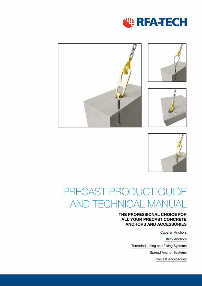
PRECAST PRODUCT GUIDE AND TECHNICAL MANUAL
THE PROFESSIONAL CHOICE FOR ALL YOUR PRECAST CONCRETE
ANCHORS AND ACCESSORIES
Construction Accessories
Con
stru
ctio
n A
cces
sorie
s w
ww
.rfa
-tec
h.co
.uk
Construction A
ccessories w
ww
.rfa-tech.co.uk
THE COMPLETE PACKAGE FOR ALL YOUR ACCESSORY NEEDS
ALL-PURPOSE ACCESSORIES
WATERPROOFING
• Waterstops
• Waterproof Membranes
• Liquid Applied Membranes
• Joint Fillers and Sealants
REINFORCEMENT ACCESSORIES
• Tying Wire & Spacers
• Slab Accessories
• Remedial Couplers
• Test Equipment
FORMWORK PRODUCTS
• Tie Bar Systems
• Corrugated Formwork
• Column Formers
• Hyrib Permanent Formwork
CHEMICALS
• Formwork Treatments
• Cementitious Repair
• Curing & Retarder Products
• Sealing & Coating Products
GROUND ENGINEERING
• Gabions, Galfan & PVC • Geotextiles
MANUFACTURED SOLUTIONS AND PRECAST SYSTEMS
SPREAD ANCHOR SYSTEM
UTILITY ANCHOR
CAPSTAN ANCHOR SYSTEM
THREADED SYSTEM
STARTABOX
COUPLERBOX
SHEARTECH
For more information call 0870 011 2881 or order online at www.rfa-tech.co.uk
J14911 RFA Concrete Show-V1.indd All Pages 13/02/2014 13:45
Capstan Anchors
Utility Anchors
Threaded Lifting and Fixing Systems
Spread Anchor Systems
Precast Accessories
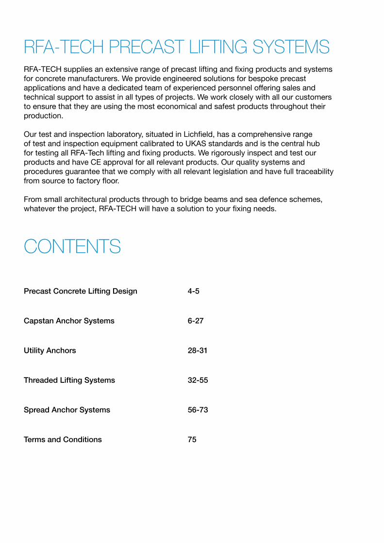
RFA-TECH PRECAST LIFTING SYSTEMSRFA-TECH supplies an extensive range of precast lifting and fixing products and systems for concrete manufacturers. We provide engineered solutions for bespoke precast applications and have a dedicated team of experienced personnel offering sales and technical support to assist in all types of projects. We work closely with all our customers to ensure that they are using the most economical and safest products throughout their production.
Our test and inspection laboratory, situated in Lichfield, has a comprehensive range of test and inspection equipment calibrated to UKAS standards and is the central hub for testing all RFA-Tech lifting and fixing products. We rigorously inspect and test our products and have CE approval for all relevant products. Our quality systems and procedures guarantee that we comply with all relevant legislation and have full traceability from source to factory floor.
From small architectural products through to bridge beams and sea defence schemes, whatever the project, RFA-TECH will have a solution to your fixing needs.
CONTENTS
Precast Concrete Lifting Design 4-5
Capstan Anchor Systems 6-27
Utility Anchors 28-31
Threaded Lifting Systems 32-55
Spread Anchor Systems 56-73
Terms and Conditions 75
3
e-mail: [email protected] www.rfa-tech.co.uk
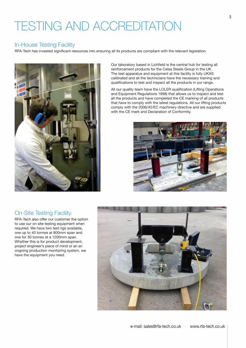
TESTING AND ACCREDITATIONIn-House Testing Facility RFA-Tech has invested significant resources into ensuring all its products are compliant with the relevant legislation.
Our laboratory based in Lichfield is the central hub for testing all reinforcement products for the Celsa Steels Group in the UK. The test apparatus and equipment at this facility is fully UKAS calibrated and all the technicians have the necessary training and qualifications to test and inspect all the products in our range.
All our quality team have the LOLER qualification (Lifting Operations and Equipment Regulations 1998) that allows us to inspect and test all the products and have completed the CE marking of all products that have to comply with the latest regulations. All our lifting products comply with the 2006/42/EC machinery directive and are supplied with the CE mark and Declaration of Conformity.
On-Site Testing Facility. RFA-Tech also offer our customer the option to use our on site testing equipment when required. We have two test rigs available, one up to 40 tonnes at 800mm span and one for 30 tonnes at a 1200mm span. Whether this is for product development, project engineer’s piece of mind or an an ongoing production monitoring system, we have the equipment you need.
Technical Product Data
Reinforcement
All reinforcement bar used in the Startabox system is of grade B500C conforming to BS4449. Startabox is available containing 8mm to 20mm reinforcement with 12mm and 16mm being the most commonly used sizes. The rebar material is specially selected to be suitable for rebending, a prerequisite of the system, and is cut and bent to meet the requirements of BS8666, specific requirements of CARES Appendix TA2 and in line with the CARES Technical Approval on the Startabox system.
All reinforcement used is tested regularly, both in-house and independently, to ensure it continues to meet the requirements of BS4449 once rebent, offering confidence to detailers and engineers and supported by relevant and recent testing data.
Case
Startabox cases are manufactured from galvanised mild steel sheet rolled to precise dimensions. The cases are fully perforated on all faces to provide an excellent bond to the first concrete pour and provide an efficient key for the subsequent pour. The cases are annealed at specific points along the case to ease nailing when fixing to formwork. A wide range of case sizes are available to suit the rebar detail requirement.
Lid Cover
The Startabox system is fitted with a plastic tear off lid, to allow easy removal once required. The plastic lid has the advantages of no sharp edges, low weight, minimal concrete adherence and is suitable for recycling. Where necessary or requested, steel lid covers can be fitted.
End Cap Seal
Startabox cases are fitted with two easily removable plastic end cap seals. These ensure the concrete cannot enter the casing. End cap seals are suitable for recycling once removed.
Telephone: 0870 011 2881
6
Curved Startbox
4
Telephone: 0870 011 2881
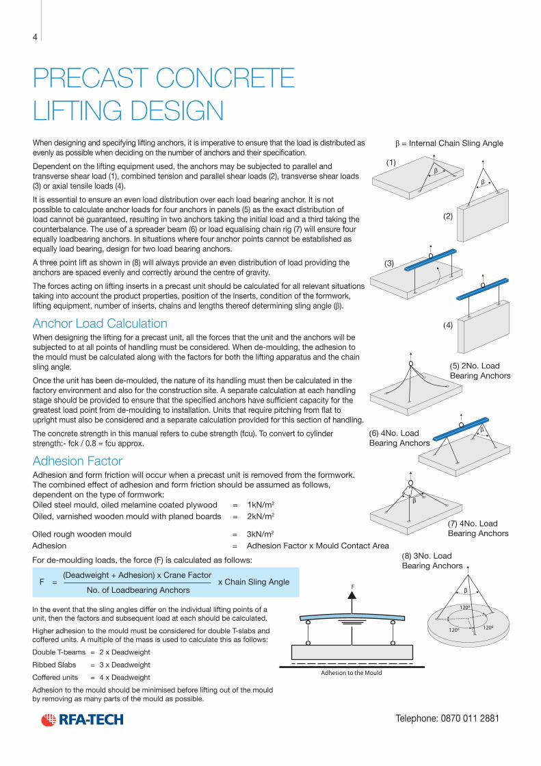
PRECAST CONCRETE LIFTING DESIGNWhen designing and specifying lifting anchors, it is imperative to ensure that the load is distributed as evenly as possible when deciding on the number of anchors and their specification.
Dependent on the lifting equipment used, the anchors may be subjected to parallel and transverse shear load (1), combined tension and parallel shear loads (2), transverse shear loads (3) or axial tensile loads (4).
It is essential to ensure an even load distribution over each load bearing anchor. It is not possible to calculate anchor loads for four anchors in panels (5) as the exact distribution of load cannot be guaranteed, resulting in two anchors taking the initial load and a third taking the counterbalance. The use of a spreader beam (6) or load equalising chain rig (7) will ensure four equally loadbearing anchors. In situations where four anchor points cannot be established as equally load bearing, design for two load bearing anchors.
A three point lift as shown in (8) will always provide an even distribution of load providing the anchors are spaced evenly and correctly around the centre of gravity.
The forces acting on lifting inserts in a precast unit should be calculated for all relevant situations taking into account the product properties, position of the inserts, condition of the formwork, lifting equipment, number of inserts, chains and lengths thereof determining sling angle (β).
Anchor Load CalculationWhen designing the lifting for a precast unit, all the forces that the unit and the anchors will be subjected to at all points of handling must be considered. When de-moulding, the adhesion to the mould must be calculated along with the factors for both the lifting apparatus and the chain sling angle.
Once the unit has been de-moulded, the nature of its handling must then be calculated in the factory environment and also for the construction site. A separate calculation at each handling stage should be provided to ensure that the specified anchors have sufficient capacity for the greatest load point from de-moulding to installation. Units that require pitching from flat to upright must also be considered and a separate calculation provided for this section of handling.
The concrete strength in this manual refers to cube strength (fcu). To convert to cylinder strength:- fck / 0.8 = fcu approx.
Adhesion FactorAdhesion and form friction will occur when a precast unit is removed from the formwork. The combined effect of adhesion and form friction should be assumed as follows, dependent on the type of formwork:Oiled steel mould, oiled melamine coated plywood = 1kN/m2
Oiled, varnished wooden mould with planed boards = 2kN/m2
β = Internal Chain Sling Angle
β
β
β
β
β
120º
120º 120º
Adhesion to the Mould
F
(1)
(2)
(3)
(4)
(6) 4No. Load Bearing Anchors
(5) 2No. Load Bearing Anchors
(7) 4No. Load Bearing Anchors
(8) 3No. Load Bearing Anchors
In the event that the sling angles differ on the individual lifting points of a unit, then the factors and subsequent load at each should be calculated.
Higher adhesion to the mould must be considered for double T-slabs and coffered units. A multiple of the mass is used to calculate this as follows:
Double T-beams = 2 x Deadweight
Ribbed Slabs = 3 x Deadweight
Coffered units = 4 x Deadweight
Adhesion to the mould should be minimised before lifting out of the mould by removing as many parts of the mould as possible.
Oiled rough wooden mould = 3kN/m2
Adhesion = Adhesion Factor x Mould Contact Area
For de-moulding loads, the force (F) is calculated as follows:
F = (Deadweight + Adhesion) x Crane Factor
x Chain Sling Angle No. of Loadbearing Anchors
5
e-mail: [email protected] www.rfa-tech.co.uk
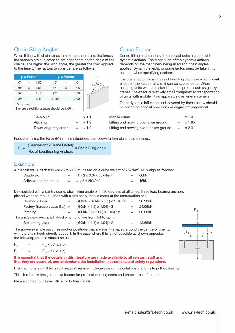
Chain Sling Angles When lifting with chain slings in a triangular pattern, the forces the anchors are subjected to are dependent on the angle of the chains. The higher the sling angle, the greater the load applied to the insert. The factors to consider are as follows:
β = Factor β = Factor
0° = 1.00 15° = 1.01
30° = 1.04 45° = 1.08
60° = 1.16 75° = 1.26
90° = 1.41 ≥120° = 2.00
Please note: The preferred lifting angle should be ≤ 60°.
Crane FactorDuring lifting and handling, the precast units are subject to dynamic actions. The magnitude of the dynamic actions depends on the machinery being used and chain angles applied. Dynamic effects, or crane factor, must be taken into account when specifying anchors.
The crane factor for all areas of handling can have a significant effect on the loads that a unit can be subjected to. When handling units with precision lifting equipment such as gantry cranes, the effect is relatively small compared to transportation of units with mobile lifting apparatus over uneven terrain.
Other dynamic influences not covered by these below should be based on special provisions or engineer’s judgement.
De-Mould = x 1.1 Mobile crane = x 1.4
Pitching = x 1.3 Lifting and moving over even ground = x 1.65
Tower or gantry crane = x 1.2 Lifting and moving over uneven ground = x 2.0
For determining the force (F) in lifting situations, the following formula should be used:
F =
(Deadweight x Crane Factor) x Chain Sling Angle
No. of Loadbearing Anchors
ExampleA precast wall unit that is 4m x 2m x 0.3m, based on a cube weight of 25kN/m3 will weigh as follows:
Deadweight = (4 x 2 x 0.3) x 25kN/m3 = 60kN
Adhesion to the mould = 4 x 2 x 2kN/m2 = 16kN
De-moulded with a gantry crane, chain sling angle of β =30 degrees at all times, three load bearing anchors, planed wooden mould. Lifted with a stationary mobile crane at the construction site.
De-mould Load = (((60kN + 16kN) x 1.1) x 1.04) / 3 = 28.98kN
Factory Transport Load (flat) = ((60kN x 1.2) x 1.04) / 3 = 24.96kN
Pitching = (((60kN / 2) x 1.3) x 1.04) / 2 = 20.28kN
The unit’s deadweight is halved when pitching from flat to upright.
Site Lifting Load = ((60kN x 1.4) x 1.04) / 2 = 43.68kN
The above example assumes anchor positions that are evenly spaced around the centre of gravity, with the chain hook directly above it. In the case where this is not possible as shown opposite, the following formula should be used:
F1 = Ftot x b / (a + b)
F2 = Ftot x a / (a + b)
It is essential that the details in this literature are made available to all relevant staff and that they are aware of, and understand the installation instructions and safety regulations.
RFA-Tech offers a full technical support service, including design calculations and on site pullout testing.
This literature is designed as guidance for professional engineers and precast manufacturers.
Please contact our sales office for further details.
β
F
Fβ/2
Ftot
F1 F2a b
Technical Product Data
Reinforcement
All reinforcement bar used in the Startabox system is of grade B500C conforming to BS4449. Startabox is available containing 8mm to 20mm reinforcement with 12mm and 16mm being the most commonly used sizes. The rebar material is specially selected to be suitable for rebending, a prerequisite of the system, and is cut and bent to meet the requirements of BS8666, specific requirements of CARES Appendix TA2 and in line with the CARES Technical Approval on the Startabox system.
All reinforcement used is tested regularly, both in-house and independently, to ensure it continues to meet the requirements of BS4449 once rebent, offering confidence to detailers and engineers and supported by relevant and recent testing data.
Case
Startabox cases are manufactured from galvanised mild steel sheet rolled to precise dimensions. The cases are fully perforated on all faces to provide an excellent bond to the first concrete pour and provide an efficient key for the subsequent pour. The cases are annealed at specific points along the case to ease nailing when fixing to formwork. A wide range of case sizes are available to suit the rebar detail requirement.
Lid Cover
The Startabox system is fitted with a plastic tear off lid, to allow easy removal once required. The plastic lid has the advantages of no sharp edges, low weight, minimal concrete adherence and is suitable for recycling. Where necessary or requested, steel lid covers can be fitted.
End Cap Seal
Startabox cases are fitted with two easily removable plastic end cap seals. These ensure the concrete cannot enter the casing. End cap seals are suitable for recycling once removed.
Telephone: 0870 011 2881
6
Curved Startbox
6
Telephone: 0870 011 2881
RFA-TECH CAPSTAN ANCHOR SYSTEMThe Capstan Anchors are a safe, simple and effective system for lifting most types of precast concrete units. The anchors are hot drop forged from high grade steel and, provided the anchor is specified and installed correctly, provide safe and secure lifting, turning and transportation of units. Anchors are available in black, zinc plated, galvanised, 304 and 316 stainless steel.
The system consists of three main components, the anchor (also known as pins, spherical head or modform), a recess former and a lifting attachment known as a shackle that links the anchor to the crane hook. They are produced in load groups from 1.3t to 32.0t and there is a length and material to suit almost all precast units.
Each anchor is stamped with the manufacturers identification mark, safe working load rating of the anchor, the batch number and CE mark. Lifting Shackles are also marked with the load group, CE mark along with the manufacturing date stamp and an individual index number for full traceability of the system. All products are rigorously tested, inspected and are supplied with Declarations of Conformity with each order along with safe working instructions where applicable.
The design of the system prevents the mismatch of load groups, as only the appropriate shackle will fit the anchor it is intended to use.
Capstan Anchors are designed for de-moulding, pitching, transport and site fixing. It is likely that there will be numerous lifting operations from production to installation, so the handling at each point should be carefully considered at each stage, and an appropriate load group and length should be selected. These anchors should not be used for repeated lifting applications over a prolonged period of time. If pitching of units is required with Capstan Anchors, please contact RFA-Tech for technical assistance.
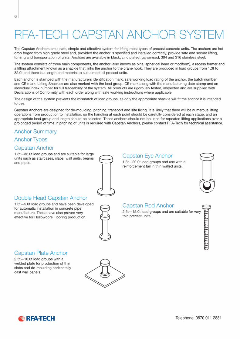
Anchor Summary Anchor Types
Capstan Anchor1.3t—32.0t load groups and are suitable for large units such as staircases, slabs, wall units, beams and pipes.
Double Head Capstan Anchor1.3t—5.0t load groups and have been developed for automatic installation in concrete pipe manufacture. These have also proved very effective for Hollowcore Flooring production.
Capstan Plate Anchor2.5t—10.0t load groups with a welded plate for production of thin slabs and de-moulding horizontally cast wall panels.
Capstan Eye Anchor1.3t—20.0t load groups and use with a reinforcement tail in thin walled units.
Capstan Rod Anchor2.5t—15.0t load groups and are suitable for very thin precast units.
7
e-mail: [email protected] www.rfa-tech.co.uk
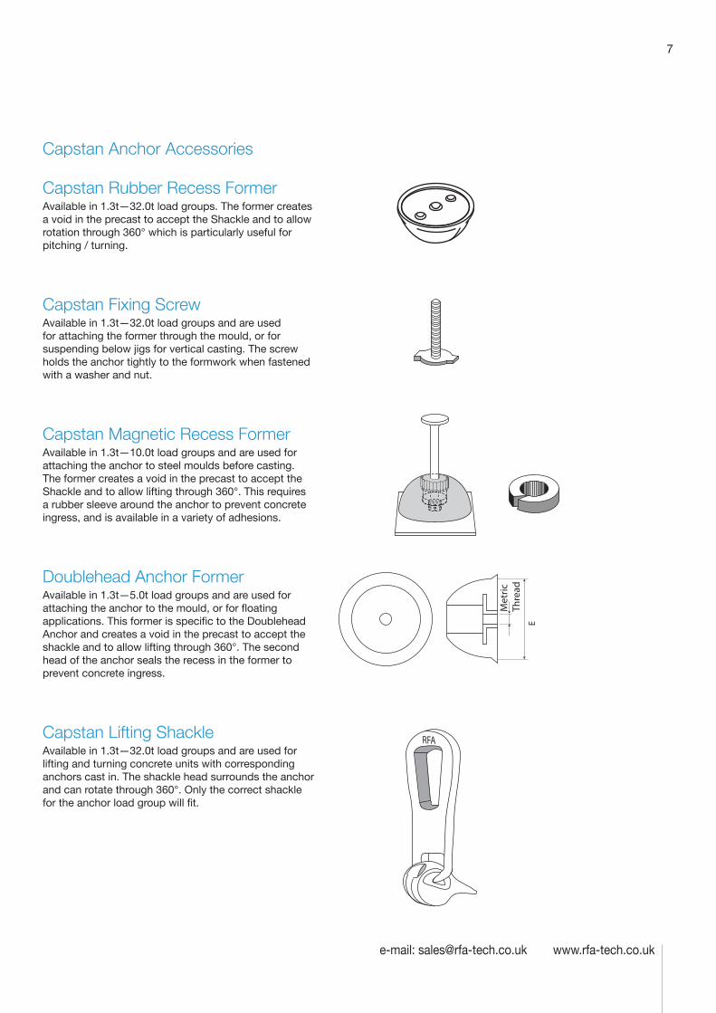
Capstan Anchor Accessories
Capstan Rubber Recess FormerAvailable in 1.3t—32.0t load groups. The former creates a void in the precast to accept the Shackle and to allow rotation through 360° which is particularly useful for pitching / turning.
Capstan Fixing ScrewAvailable in 1.3t—32.0t load groups and are used for attaching the former through the mould, or for suspending below jigs for vertical casting. The screw holds the anchor tightly to the formwork when fastened with a washer and nut.
Capstan Magnetic Recess FormerAvailable in 1.3t—10.0t load groups and are used for attaching the anchor to steel moulds before casting. The former creates a void in the precast to accept the Shackle and to allow lifting through 360°. This requires a rubber sleeve around the anchor to prevent concrete ingress, and is available in a variety of adhesions.
Doublehead Anchor FormerAvailable in 1.3t—5.0t load groups and are used for attaching the anchor to the mould, or for floating applications. This former is specific to the Doublehead Anchor and creates a void in the precast to accept the shackle and to allow lifting through 360°. The second head of the anchor seals the recess in the former to prevent concrete ingress.
Capstan Lifting ShackleAvailable in 1.3t—32.0t load groups and are used for lifting and turning concrete units with corresponding anchors cast in. The shackle head surrounds the anchor and can rotate through 360°. Only the correct shackle for the anchor load group will fit.
E
Met
ric
Thre
ad
Technical Product Data
Reinforcement
All reinforcement bar used in the Startabox system is of grade B500C conforming to BS4449. Startabox is available containing 8mm to 20mm reinforcement with 12mm and 16mm being the most commonly used sizes. The rebar material is specially selected to be suitable for rebending, a prerequisite of the system, and is cut and bent to meet the requirements of BS8666, specific requirements of CARES Appendix TA2 and in line with the CARES Technical Approval on the Startabox system.
All reinforcement used is tested regularly, both in-house and independently, to ensure it continues to meet the requirements of BS4449 once rebent, offering confidence to detailers and engineers and supported by relevant and recent testing data.
Case
Startabox cases are manufactured from galvanised mild steel sheet rolled to precise dimensions. The cases are fully perforated on all faces to provide an excellent bond to the first concrete pour and provide an efficient key for the subsequent pour. The cases are annealed at specific points along the case to ease nailing when fixing to formwork. A wide range of case sizes are available to suit the rebar detail requirement.
Lid Cover
The Startabox system is fitted with a plastic tear off lid, to allow easy removal once required. The plastic lid has the advantages of no sharp edges, low weight, minimal concrete adherence and is suitable for recycling. Where necessary or requested, steel lid covers can be fitted.
End Cap Seal
Startabox cases are fitted with two easily removable plastic end cap seals. These ensure the concrete cannot enter the casing. End cap seals are suitable for recycling once removed.
Telephone: 0870 011 2881
6
Curved Startbox
8
Telephone: 0870 011 2881
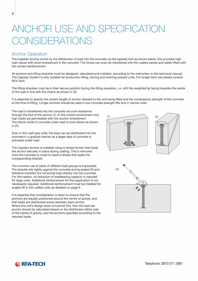
ANCHOR USE AND SPECIFICATION CONSIDERATIONSAnchor OperationThe Capstan Anchor works by the distribution of load into the concrete via the tapered foot as shown below, this provides high load values with short embedment in the concrete. The forces can even be transferred into thin walled panels and safely lifted with the correct reinforcement.
All anchors and lifting shackles must be designed, calculated and installed, according to the instruction in this technical manual. The Capstan System is only suitable for production lifting, storing and erecting precast units. For longer term use please consult RFA-Tech.
The lifting shackles must be in their secure position during the lifting operation, i.e. with the weighted lip facing towards the centre of the load in line with the chains as shown in (3).
It is essential to specify the correct length of anchor relevant to the unit being lifted and the compressive strength of the concrete at the time of lifting. Longer anchors should be used in low concrete strength lifts and in narrow units.
(1) (2)
(3)
The load is transferred into the concrete via cone resistance through the foot of the anchor (1). In the correct environment very high loads are permissible with low anchor embedment. The failure mode of concrete under load is cone failure as shown in (2).
Even in thin wall type units, the load can be distributed into the concrete in a gradual manner as a larger area of concrete is activated under load.
The Capstan Anchor is installed using a recess former that holds the anchor securely in place during casting. This is removed once the concrete is cured to leave a recess that seats the corresponding shackle.
The incorrect use of parts of different load groups is impossible. The shackle sits tightly against the concrete during angled lift and therefore transfers the horizontal load directly into the concrete. For this reason, no reduction of loadbearing capacity is required for large units. Additional reinforcement for this application is not necessarily required. Additional reinforcement must be installed for angled lift in thin walled units as detailed on page 9.
It is essential that consideration is taken to ensure that the anchors are equally positioned around the centre of gravity, and that loads are distributed evenly between each anchor. Where the unit’s design does not permit this, then the load per anchor should be calculated based on the distribution either side of the centre of gravity, and the anchors specified according to the required loads.
9
e-mail: [email protected] www.rfa-tech.co.uk
INSTALLATION IN WALLS AND BEAMS—ADDITIONAL REINFORCEMENT REQUIREMENTS
e
Slot-in link, (positioned as close to anchor as possible)
ez/2
D2
Square mesh reinforcement
D
ß/2
B
C
A
B
D
D
Edge reinforcement
Always insert angled lift linkopposite the direction of the load
Leng
th o
f slo
t-in
link
L tot =
Lt +
L
Lt1 = total length(approx. 2 x length of leg)Angled lift reinforcement
AID1
Reinforced area 3 times anchor length L
l t
D1
D3(2
)
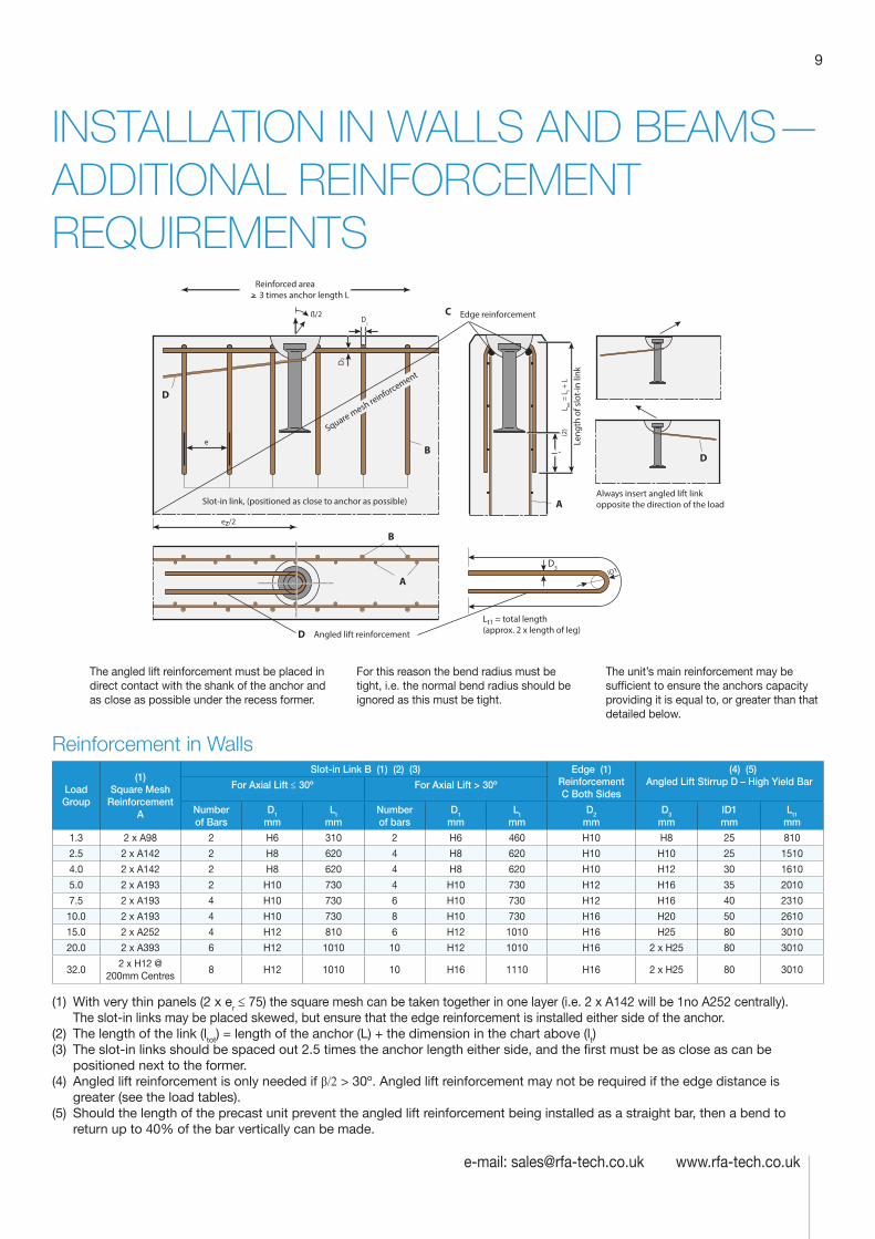
The angled lift reinforcement must be placed in direct contact with the shank of the anchor and as close as possible under the recess former.
For this reason the bend radius must be tight, i.e. the normal bend radius should be ignored as this must be tight.
The unit’s main reinforcement may be sufficient to ensure the anchors capacity providing it is equal to, or greater than that detailed below.
Reinforcement in Walls
Load Group
(1) Square Mesh
Reinforcement A
Slot-in Link B (1) (2) (3) Edge (1) Reinforcement C Both Sides
(4) (5) Angled Lift Stirrup D – High Yield Bar For Axial Lift ≤ 30º For Axial Lift > 30º
Number of Bars
D1 mm
Lt mm
Number of bars
D1 mm
Lt mm
D2 mm
D3 mm
ID1 mm
Lt1 mm
1.3 2 x A98 2 H6 310 2 H6 460 H10 H8 25 810
2.5 2 x A142 2 H8 620 4 H8 620 H10 H10 25 1510
4.0 2 x A142 2 H8 620 4 H8 620 H10 H12 30 1610
5.0 2 x A193 2 H10 730 4 H10 730 H12 H16 35 2010
7.5 2 x A193 4 H10 730 6 H10 730 H12 H16 40 2310
10.0 2 x A193 4 H10 730 8 H10 730 H16 H20 50 2610
15.0 2 x A252 4 H12 810 6 H12 1010 H16 H25 80 3010
20.0 2 x A393 6 H12 1010 10 H12 1010 H16 2 x H25 80 3010
32.02 x H12 @
200mm Centres8 H12 1010 10 H16 1110 H16 2 x H25 80 3010
(1) With very thin panels (2 x er ≤ 75) the square mesh can be taken together in one layer (i.e. 2 x A142 will be 1no A252 centrally). The slot-in links may be placed skewed, but ensure that the edge reinforcement is installed either side of the anchor.
(2) The length of the link (ltot) = length of the anchor (L) + the dimension in the chart above (lt)(3) The slot-in links should be spaced out 2.5 times the anchor length either side, and the first must be as close as can be
positioned next to the former.(4) Angled lift reinforcement is only needed if β/2 > 30º. Angled lift reinforcement may not be required if the edge distance is
greater (see the load tables).(5) Should the length of the precast unit prevent the angled lift reinforcement being installed as a straight bar, then a bend to
return up to 40% of the bar vertically can be made.
Technical Product Data
Reinforcement
All reinforcement bar used in the Startabox system is of grade B500C conforming to BS4449. Startabox is available containing 8mm to 20mm reinforcement with 12mm and 16mm being the most commonly used sizes. The rebar material is specially selected to be suitable for rebending, a prerequisite of the system, and is cut and bent to meet the requirements of BS8666, specific requirements of CARES Appendix TA2 and in line with the CARES Technical Approval on the Startabox system.
All reinforcement used is tested regularly, both in-house and independently, to ensure it continues to meet the requirements of BS4449 once rebent, offering confidence to detailers and engineers and supported by relevant and recent testing data.
Case
Startabox cases are manufactured from galvanised mild steel sheet rolled to precise dimensions. The cases are fully perforated on all faces to provide an excellent bond to the first concrete pour and provide an efficient key for the subsequent pour. The cases are annealed at specific points along the case to ease nailing when fixing to formwork. A wide range of case sizes are available to suit the rebar detail requirement.
Lid Cover
The Startabox system is fitted with a plastic tear off lid, to allow easy removal once required. The plastic lid has the advantages of no sharp edges, low weight, minimal concrete adherence and is suitable for recycling. Where necessary or requested, steel lid covers can be fitted.
End Cap Seal
Startabox cases are fitted with two easily removable plastic end cap seals. These ensure the concrete cannot enter the casing. End cap seals are suitable for recycling once removed.
Telephone: 0870 011 2881
6
Curved Startbox
10
Telephone: 0870 011 2881
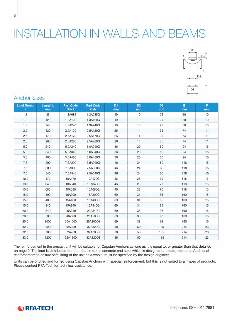
INSTALLATION IN WALLS AND BEAMS
Load Group t
Length L mm
Part Code Black
Part Code Galv
D1 mm
D2 mm
D3 mm
E mm
F mm
1.3 85 1.3A085 1.3A085G 19 10 25 60 10
1.3 120 1.3A120 1.3A120G 19 10 25 60 10
1.3 240 1.3A240 1.3A240G 19 10 25 60 10
2.5 120 2.5A120 2.5A120G 26 14 35 74 11
2.5 170 2.5A170 2.5A170G 26 14 35 74 11
2.5 280 2.5A280 2.5A280G 26 14 35 74 11
5.0 240 5.0A240 5.0A240G 36 20 50 94 15
5.0 340 5.0A340 5.0A340G 36 20 50 94 15
5.0 480 5.0A480 5.0A480G 36 20 50 94 15
7.5 200 7.5A200 7.5A200G 46 24 60 118 15
7.5 300 7.5A300 7.5A300G 46 24 60 118 15
7.5 540 7.5A540 7.5A540G 46 24 60 118 15
10.0 170 10A170 10A170G 46 28 70 118 15
10.0 340 10A340 10A340G 46 28 70 118 15
10.0 680 10A680 10A680G 46 28 70 118 15
15.0 300 15A300 15A300G 69 34 85 160 15
15.0 400 15A400 15A400G 69 34 85 160 15
15.0 840 15A840 15A840G 69 34 85 160 15
20.0 340 20A340 20A340G 69 38 98 160 15
20.0 500 20A500 20A500G 69 38 98 160 15
20.0 1000 20A1000 20A1000G 69 38 98 160 15
32.0 320 32A320 32A320G 88 50 135 214 23
32.0 700 32A700 32A700G 88 50 135 214 23
32.0 1200 32A1200 32A1200G 88 50 135 214 23
The reinforcement in the precast unit will be suitable for Capstan Anchors as long as it is equal to, or greater than that detailed on page 9. The load is distributed from the foot in to the concrete and steel which is designed to protect the cone. Additional reinforcement to ensure safe lifting of the unit as a whole, must be specified by the design engineer.
Units can be pitched and turned using Capstan Anchors with special reinforcement, but this is not suited to all types of products. Please contact RFA-Tech for technical assistance.
D1
D3
D2
EL
F
Anchor Sizes
11
e-mail: [email protected] www.rfa-tech.co.uk
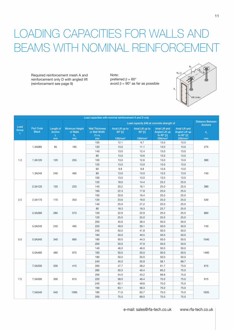
LOADING CAPACITIES FOR WALLS AND BEAMS WITH NOMINAL REINFORCEMENT
Load capacities with nominal reinforcement A and D only
Load Group
t
Part Code Black
Load capacity (kN) at concrete strength ofDistance Between
AnchorsLength of Anchor
L mm
Minimum Height of Walls
A1 mm
Wall Thickness or Wall Width
2 x er mm
Axial Lift up to 60º [β]
15N/mm2
Axial Lift up to 90º [β]
15N/mm2
Axial Lift and Angled Lift up
to 90º [β] 25N/mm2
Axial Lift and Angled Lift up
to 90º [β] 35N/mm2
ez
mm
1.3
1.3A085 85 185
100 12.1 9.7 13.0 13.0
275120 13.0 11.1 13.0 13.0
140 13.0 12.4 13.0 13.0
1.3A120 120 255
80 13.0 10.6 13.0 13.0
380100 13.0 12.6 13.0 13.0
120 13.0 13.0 13.0 13.0
1.3A240 240 495
60 9.8 9.8 12.6 13.0
74080 13.0 13.0 13.0 13.0
100 13.0 13.0 13.0 13.0
2.5
2.5A120 120 253
120 18.0 14.4 23.2 25.0
380140 20.2 16.1 25.0 25.0
160 22.3 17.8 25.0 25.0
2.5A170 170 353
100 20.6 16.4 25.0 25.0
530120 23.6 19.0 25.0 25.0
140 25.0 21.2 25.0 25.0
2.5A280 280 573
80 18.3 18.3 23.7 25.0
860100 22.9 22.9 25.0 25.0
120 25.0 25.0 25.0 25.0
5.0
5.0A240 240 495
200 45.6 36.4 50.0 50.0
740220 49.0 39.1 50.0 50.0
240 50.0 41.8 50.0 50.0
5.0A340 340 695
160 50.0 40.5 50.0 50.0
1040180 50.0 44.3 50.0 50.0
200 50.0 47.9 50.0 50.0
5.0A480 480 975
140 46.0 46.0 50.0 50.0
1460160 50.0 50.0 50.0 50.0
180 50.0 50.0 50.0 50.0
7.5
7.5A200 200 415
240 45.0 35.9 58.1 68.7
615260 47.7 38.2 61.7 73.0
280 50.5 40.4 65.2 75.0
7.5A300 300 615
200 54.0 43.2 69.8 75.0
915220 58.0 46.4 75.0 75.0
240 62.1 49.6 75.0 75.0
7.5A540 540 1095
160 63.1 58.3 75.0 75.0
1635180 71.0 63.7 75.0 75.0
200 75.0 69.0 75.0 75.0
H8 Links
A1
Note: preferred β = 60° avoid β = 90° as far as possible
Required reinforcement mesh A and reinforcement only D with angled lift (reinforcement see page 9)
Technical Product Data
Reinforcement
All reinforcement bar used in the Startabox system is of grade B500C conforming to BS4449. Startabox is available containing 8mm to 20mm reinforcement with 12mm and 16mm being the most commonly used sizes. The rebar material is specially selected to be suitable for rebending, a prerequisite of the system, and is cut and bent to meet the requirements of BS8666, specific requirements of CARES Appendix TA2 and in line with the CARES Technical Approval on the Startabox system.
All reinforcement used is tested regularly, both in-house and independently, to ensure it continues to meet the requirements of BS4449 once rebent, offering confidence to detailers and engineers and supported by relevant and recent testing data.
Case
Startabox cases are manufactured from galvanised mild steel sheet rolled to precise dimensions. The cases are fully perforated on all faces to provide an excellent bond to the first concrete pour and provide an efficient key for the subsequent pour. The cases are annealed at specific points along the case to ease nailing when fixing to formwork. A wide range of case sizes are available to suit the rebar detail requirement.
Lid Cover
The Startabox system is fitted with a plastic tear off lid, to allow easy removal once required. The plastic lid has the advantages of no sharp edges, low weight, minimal concrete adherence and is suitable for recycling. Where necessary or requested, steel lid covers can be fitted.
End Cap Seal
Startabox cases are fitted with two easily removable plastic end cap seals. These ensure the concrete cannot enter the casing. End cap seals are suitable for recycling once removed.
Telephone: 0870 011 2881
6
Curved Startbox
12
Telephone: 0870 011 2881
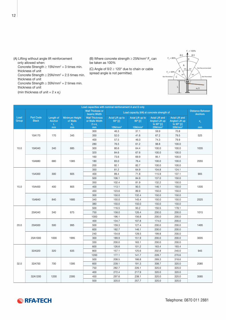
Load capacities with nominal reinforcement A and D only
Load Group
Part Code Black
Wall Thickess or beams Width
Load capacity (kN) at concrete strength ofDistance Between
AnchorsLength of Anchor
L mm
Minimum Height of Walls
A1 mm
Wall Thickness or Walls Width
2 x er mm
Axial Lift up to 60º [β]
15N/mm2
Axial Lift up to 90º [β]
15N/mm2
Axial Lift and Angled Lift up
to 90º [β] 25N/mm2
Axial Lift and Angled Lift up
to 90º [β] 35N/mm2
ez
mm
10.0
10A170 170 345
300 46.3 37.1 59.9 70.8
525350 52.0 41.6 67.2 79.5
400 57.5 46.0 74.3 79.9
10A340 340 685
280 76.5 61.2 98.8 100.0
1035300 80.6 64.4 100.0 100.0
320 84.6 67.6 100.0 100.0
10A680 680 1365
160 73.6 69.9 95.1 100.0
2055180 83.0 76.4 100.0 100.0
200 92.1 82.7 100.0 100.0
15.0
15A300 300 605
350 81.2 64.9 104.8 124.1
905400 89.4 71.8 115.9 137.1
500 106.1 84.9 137.0 150.0
15A400 400 805
350 102.4 81.9 132.2 150.0
1205400 113.1 90.5 146.1 150.0
450 123.6 89.9 150.0 150.0
15A840 840 1685
300 150.0 132.4 150.0 150.0
2525340 150.0 145.4 150.0 150.0
380 150.0 150.0 150.0 150.0
20.0
20A340 340 675
500 116.5 93.2 150.5 178.1
1015750 158.0 126.4 200.0 200.0
1000 196.1 156.8 200.0 200.0
20A500 500 995
400 134.7 107.8 174.0 200.0
1495500 159.3 127.4 200.0 200.0
600 182.7 146.1 200.0 200.0
20A1000 1000 1995
240 154.8 128.5 199.8 200.0
3005300 189.9 151.9 200.0 200.0
330 200.0 163.1 200.0 200.0
32.0
32A320 320 635
600 126.6 101.2 163.4 193.4
945800 157.1 125.6 202.8 240.0
1200 177.1 141.7 228.7 270.6
32A700 700 1395
500 208.5 166.8 269.3 318.6
2085600 239.1 191.3 308.7 320.0
750 282.7 226.1 320.0 320.0
32A1200 1200 2395
400 272.4 217.9 320.0 320.0
3585450 297.6 238.1 320.0 320.0
500 320.0 257.7 320.0 320.0
ez/2L
30º
30º
30º
30º
F1 = 100%
F2 = 80%
F3 = 50%
β/2
β
β/2
C
B
A
Not Permitted Not Permitted
Not Recommended
(A) Lifting without angle lift reinforcement only allowed when:
Concrete Strength ≥ 15N/mm2 + 3 times min. thickness of unitConcrete Strength ≥ 25N/mm2 + 2.5 times min. thickness of unitConcrete Strength ≥ 35N/mm2 + 2 times min. thickness of unit(min thickness of unit = 2 x er)
(B) Where concrete strength ≥ 25N/mm2 F2 can be taken as 100%
(C) Angle of ß/2 ≥ 120° due to chain or cable spread angle is not permitted.
13
e-mail: [email protected] www.rfa-tech.co.uk
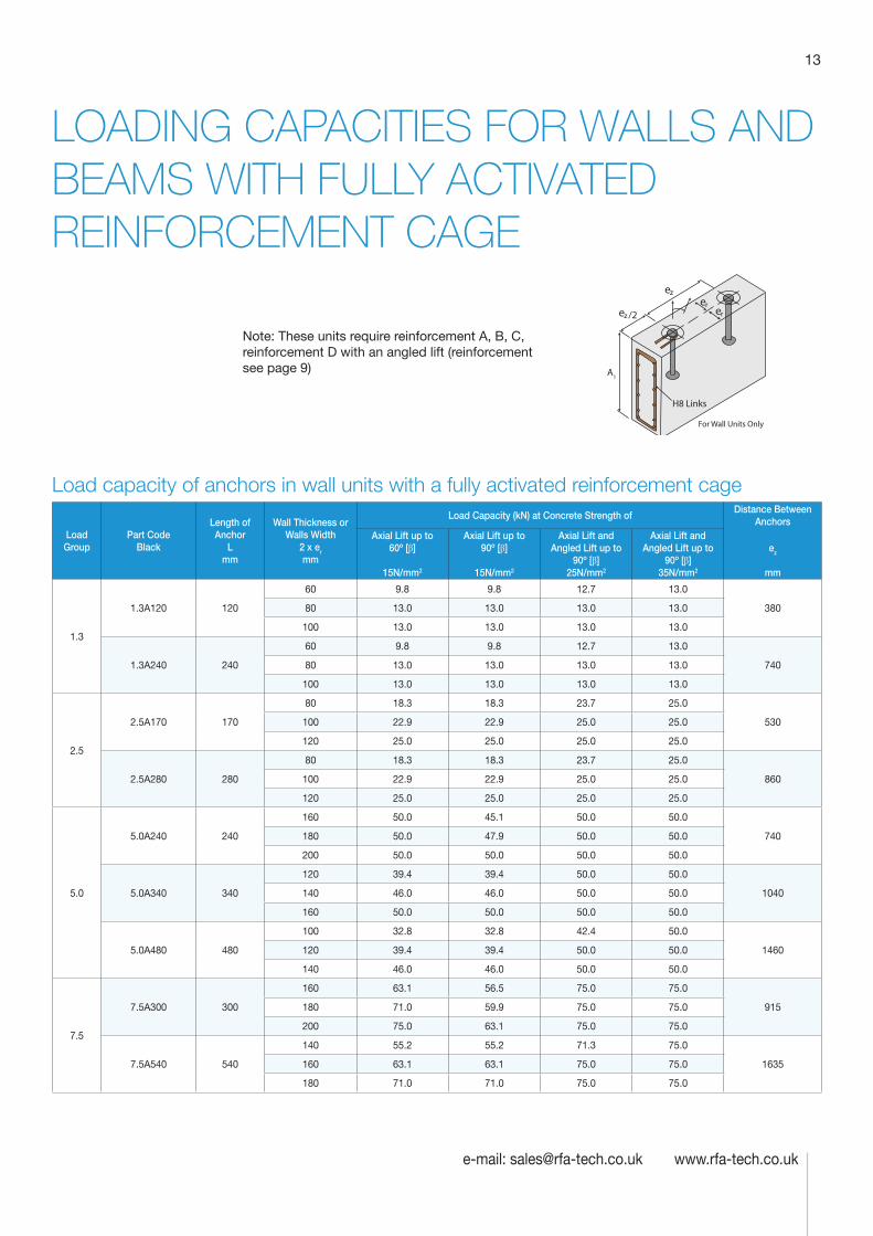
LOADING CAPACITIES FOR WALLS AND BEAMS WITH FULLY ACTIVATED REINFORCEMENT CAGE
Load capacity of anchors in wall units with a fully activated reinforcement cage
Load Group
Part Code Black
Length of Anchor
L mm
Wall Thickness or Walls Width
2 x er mm
Load Capacity (kN) at Concrete Strength ofDistance Between
AnchorsAxial Lift up to
60º [β]
15N/mm2
Axial Lift up to 90º [β]
15N/mm2
Axial Lift and Angled Lift up to
90º [β] 25N/mm2
Axial Lift and Angled Lift up to
90º [β] 35N/mm2
ez
mm
1.3
1.3A120 120
60 9.8 9.8 12.7 13.0
38080 13.0 13.0 13.0 13.0
100 13.0 13.0 13.0 13.0
1.3A240 240
60 9.8 9.8 12.7 13.0
74080 13.0 13.0 13.0 13.0
100 13.0 13.0 13.0 13.0
2.5
2.5A170 170
80 18.3 18.3 23.7 25.0
530100 22.9 22.9 25.0 25.0
120 25.0 25.0 25.0 25.0
2.5A280 280
80 18.3 18.3 23.7 25.0
860100 22.9 22.9 25.0 25.0
120 25.0 25.0 25.0 25.0
5.0
5.0A240 240
160 50.0 45.1 50.0 50.0
740180 50.0 47.9 50.0 50.0
200 50.0 50.0 50.0 50.0
5.0A340 340
120 39.4 39.4 50.0 50.0
1040140 46.0 46.0 50.0 50.0
160 50.0 50.0 50.0 50.0
5.0A480 480
100 32.8 32.8 42.4 50.0
1460120 39.4 39.4 50.0 50.0
140 46.0 46.0 50.0 50.0
7.5
7.5A300 300
160 63.1 56.5 75.0 75.0
915180 71.0 59.9 75.0 75.0
200 75.0 63.1 75.0 75.0
7.5A540 540
140 55.2 55.2 71.3 75.0
1635160 63.1 63.1 75.0 75.0
180 71.0 71.0 75.0 75.0
For Wall Units Only
H8 Links
A1
Note: These units require reinforcement A, B, C, reinforcement D with an angled lift (reinforcement see page 9)

Technical Product Data
Reinforcement
All reinforcement bar used in the Startabox system is of grade B500C conforming to BS4449. Startabox is available containing 8mm to 20mm reinforcement with 12mm and 16mm being the most commonly used sizes. The rebar material is specially selected to be suitable for rebending, a prerequisite of the system, and is cut and bent to meet the requirements of BS8666, specific requirements of CARES Appendix TA2 and in line with the CARES Technical Approval on the Startabox system.
All reinforcement used is tested regularly, both in-house and independently, to ensure it continues to meet the requirements of BS4449 once rebent, offering confidence to detailers and engineers and supported by relevant and recent testing data.
Case
Startabox cases are manufactured from galvanised mild steel sheet rolled to precise dimensions. The cases are fully perforated on all faces to provide an excellent bond to the first concrete pour and provide an efficient key for the subsequent pour. The cases are annealed at specific points along the case to ease nailing when fixing to formwork. A wide range of case sizes are available to suit the rebar detail requirement.
Lid Cover
The Startabox system is fitted with a plastic tear off lid, to allow easy removal once required. The plastic lid has the advantages of no sharp edges, low weight, minimal concrete adherence and is suitable for recycling. Where necessary or requested, steel lid covers can be fitted.
End Cap Seal
Startabox cases are fitted with two easily removable plastic end cap seals. These ensure the concrete cannot enter the casing. End cap seals are suitable for recycling once removed.
Telephone: 0870 011 2881
6
Curved Startbox
14
Telephone: 0870 011 2881
Load GroupPart Code
Black
Load Capacity (kN) at Concrete Strength ofDistance Between
AnchorsLength of Anchor
L mm
Wall Thickness or Walls Width
2 x er mm
Axial Lift up to 60º [β]
15N/mm2
Axial Lift up to 90º [β]
15N/mm2
Axial Lift and Angled Lift up to
90º [β] 25N/mm2
Axial Lift and Angled Lift up to
90º [β] 35N/mm2
ez
mm
10.0
10A340 340
200 89.4 71.5 100.0 100.0
1035240 97.9 78.3 100.0 100.0
280 100.0 84.6 100.0 100.0
10A680 680
160 73.6 73.6 95.1 100.0
2055180 82.9 82.9 100.0 100.0
200 92.1 92.1 100.0 100.0
15.0
15A400 400
300 128.8 103.0 150.0 150.0
1205400 148.8 119.0 150.0 150.0
500 150.0 133.0 150.0 150.0
15A840 840
200 111.8 111.8 144.4 150.0
2525220 123.0 123.0 150.0 150.0
240 134.1 134.1 150.0 150.0
20.0
20A500 500
300 162.0 129.6 200.0 200.0
1495400 175.0 140.0 200.0 200.0
500 187.1 149.6 200.0 200.0
600 200.0 183.3 200.0 200.0
20A1000 1000
240 154.8 154.8 199.8 200.0
3005260 167.7 167.7 200.0 200.0
280 180.6 180.6 200.0 200.0
32.0
32A700 700
450 282.5 226.0 320.0 320.0
2085550 312.4 249.9 320.0 320.0
650 320.0 271.7 320.0 320.0
32A1200 1200
300 266.6 266.6 320.0 320.0
3585350 311.0 311.0 320.0 320.0
400 320.0 320.0 320.0 320.0
ez/2L
30º
30º
30º
30º
F1 = 100%
F2 = 80%
F3 = 50%
β/2
β
β/2
C
B
A
Not Permitted Not Permitted
Not Recommended
(A) Lifting without angle lift reinforcement only allowed when:
Concrete Strength ≥ 15N/mm2 + 3 times min. thickness of unitConcrete Strength ≥ 25N/mm2 + 2.5 times min. thickness of unitConcrete Strength ≥ 35N/mm2 + 2 times min. thickness of unit(min thickness of unit = 2 x er)
(B) Where concrete strength ≥ 25N/mm2 F2 can be taken as 100%
(C) Angle of ß/2 ≥ 120° due to chain or cable spread angle is not permitted.
15
e-mail: [email protected] www.rfa-tech.co.uk
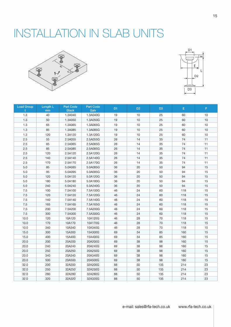
INSTALLATION IN SLAB UNITS
Load Group t
Length L mm
Part Code Black
Part Code Galv
D1 D2 D3 E F
1.3 40 1.3A040 1.3A040G 19 10 25 60 10
1.3 50 1.3A050 1.3A050G 19 10 25 60 10
1.3 65 1.3A065 1.3A065G 19 10 25 60 10
1.3 85 1.3A085 1.3A085G 19 10 25 60 10
1.3 120 1.3A120 1.3A120G 19 10 25 60 10
2.5 55 2.5A055 2.5A055G 26 14 35 74 11
2.5 65 2.5A065 2.5A065G 26 14 35 74 11
2.5 85 2.5A085 2.5A085G 26 14 35 74 11
2.5 120 2.5A120 2.5A120G 26 14 35 74 11
2.5 140 2.5A140 2.5A140G 26 14 35 74 11
2.5 170 2.5A170 2.5A170G 26 14 35 74 11
5.0 85 5.0A085 5.0A085G 36 20 50 94 15
5.0 95 5.0A095 5.0A095G 36 20 50 94 15
5.0 120 5.0A120 5.0A120G 36 20 50 94 15
5.0 180 5.0A180 5.0A180G 36 20 50 94 15
5.0 240 5.0A240 5.0A240G 36 20 50 94 15
7.5 100 7.5A100 7.5A100G 46 24 60 118 15
7.5 120 7.5A120 7.5A120G 46 24 60 118 15
7.5 140 7.5A140 7.5A140G 46 24 60 118 15
7.5 165 7.5A165 7.5A165G 46 24 60 118 15
7.5 200 7.5A200 7.5A200G 46 24 60 118 15
7.5 300 7.5A300 7.5A300G 46 24 60 118 15
10.0 120 10A120 10A120G 46 28 70 118 15
10.0 170 10A170 10A170G 46 28 70 118 15
10.0 340 10A340 10A340G 46 28 70 118 15
15.0 300 15A300 15A300G 69 34 85 160 15
15.0 400 15A400 15A400G 69 34 85 160 15
20.0 200 20A200 20A200G 69 38 98 160 15
20.0 240 20A240 20A240G 69 38 98 160 15
20.0 250 20A250 20A250G 69 38 98 160 15
20.0 340 20A340 20A340G 69 38 98 160 15
20.0 500 20A500 20A500G 69 38 98 160 15
32.0 200 32A200 32A200G 88 50 135 214 23
32.0 250 32A250 32A250G 88 50 135 214 23
32.0 280 32A280 32A280G 88 50 135 214 23
32.0 320 32A320 32A320G 88 50 135 214 23
D1
D3
D2
EL
F
Technical Product Data
Reinforcement
All reinforcement bar used in the Startabox system is of grade B500C conforming to BS4449. Startabox is available containing 8mm to 20mm reinforcement with 12mm and 16mm being the most commonly used sizes. The rebar material is specially selected to be suitable for rebending, a prerequisite of the system, and is cut and bent to meet the requirements of BS8666, specific requirements of CARES Appendix TA2 and in line with the CARES Technical Approval on the Startabox system.
All reinforcement used is tested regularly, both in-house and independently, to ensure it continues to meet the requirements of BS4449 once rebent, offering confidence to detailers and engineers and supported by relevant and recent testing data.
Case
Startabox cases are manufactured from galvanised mild steel sheet rolled to precise dimensions. The cases are fully perforated on all faces to provide an excellent bond to the first concrete pour and provide an efficient key for the subsequent pour. The cases are annealed at specific points along the case to ease nailing when fixing to formwork. A wide range of case sizes are available to suit the rebar detail requirement.
Lid Cover
The Startabox system is fitted with a plastic tear off lid, to allow easy removal once required. The plastic lid has the advantages of no sharp edges, low weight, minimal concrete adherence and is suitable for recycling. Where necessary or requested, steel lid covers can be fitted.
End Cap Seal
Startabox cases are fitted with two easily removable plastic end cap seals. These ensure the concrete cannot enter the casing. End cap seals are suitable for recycling once removed.
Telephone: 0870 011 2881
6
Curved Startbox
16
Telephone: 0870 011 2881
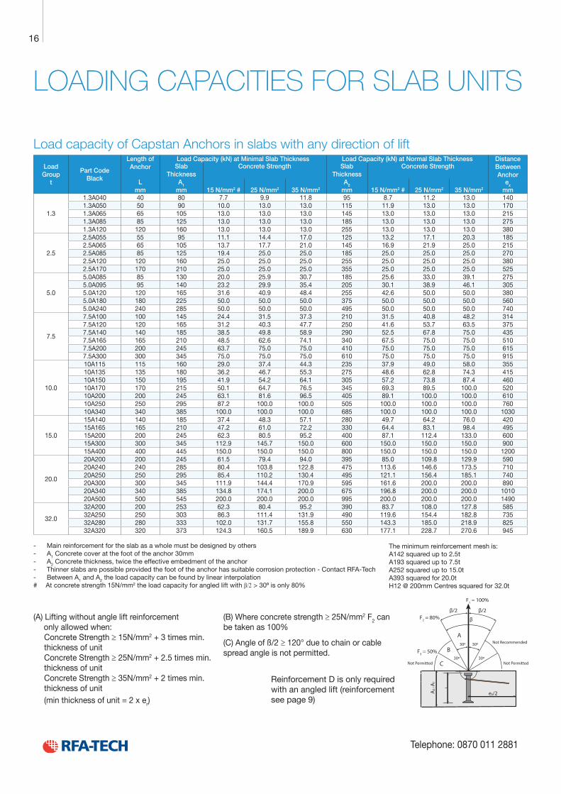
LOADING CAPACITIES FOR SLAB UNITS
Load capacity of Capstan Anchors in slabs with any direction of lift
Load Group
t
Part Code Black
Length of Anchor
Load Capacity (kN) at Minimal Slab Thickness Load Capacity (kN) at Normal Slab Thickness Distance Between Anchor
Slab Thickness
Concrete Strength Slab Thickness
Concrete Strength
L mm
A1 mm 15 N/mm2 # 25 N/mm2 35 N/mm2
A2 mm 15 N/mm2 # 25 N/mm2 35 N/mm2
ez mm
1.3
1.3A040 40 80 7.7 9.9 11.8 95 8.7 11.2 13.0 1401.3A050 50 90 10.0 13.0 13.0 115 11.9 13.0 13.0 1701.3A065 65 105 13.0 13.0 13.0 145 13.0 13.0 13.0 2151.3A085 85 125 13.0 13.0 13.0 185 13.0 13.0 13.0 2751.3A120 120 160 13.0 13.0 13.0 255 13.0 13.0 13.0 380
2.5
2.5A055 55 95 11.1 14.4 17.0 125 13.2 17.1 20.3 1852.5A065 65 105 13.7 17.7 21.0 145 16.9 21.9 25.0 2152.5A085 85 125 19.4 25.0 25.0 185 25.0 25.0 25.0 2702.5A120 120 160 25.0 25.0 25.0 255 25.0 25.0 25.0 3802.5A170 170 210 25.0 25.0 25.0 355 25.0 25.0 25.0 525
5.0
5.0A085 85 130 20.0 25.9 30.7 185 25.6 33.0 39.1 2755.0A095 95 140 23.2 29.9 35.4 205 30.1 38.9 46.1 3055.0A120 120 165 31.6 40.9 48.4 255 42.6 50.0 50.0 3805.0A180 180 225 50.0 50.0 50.0 375 50.0 50.0 50.0 5605.0A240 240 285 50.0 50.0 50.0 495 50.0 50.0 50.0 740
7.5
7.5A100 100 145 24.4 31.5 37.3 210 31.5 40.8 48.2 3147.5A120 120 165 31.2 40.3 47.7 250 41.6 53.7 63.5 3757.5A140 140 185 38.5 49.8 58.9 290 52.5 67.8 75.0 4357.5A165 165 210 48.5 62.6 74.1 340 67.5 75.0 75.0 5107.5A200 200 245 63.7 75.0 75.0 410 75.0 75.0 75.0 6157.5A300 300 345 75.0 75.0 75.0 610 75.0 75.0 75.0 915
10.0
10A115 115 160 29.0 37.4 44.3 235 37.9 49.0 58.0 35510A135 135 180 36.2 46.7 55.3 275 48.6 62.8 74.3 41510A150 150 195 41.9 54.2 64.1 305 57.2 73.8 87.4 46010A170 170 215 50.1 64.7 76.5 345 69.3 89.5 100.0 52010A200 200 245 63.1 81.6 96.5 405 89.1 100.0 100.0 61010A250 250 295 87.2 100.0 100.0 505 100.0 100.0 100.0 76010A340 340 385 100.0 100.0 100.0 685 100.0 100.0 100.0 1030
15.0
15A140 140 185 37.4 48.3 57.1 280 49.7 64.2 76.0 42015A165 165 210 47.2 61.0 72.2 330 64.4 83.1 98.4 49515A200 200 245 62.3 80.5 95.2 400 87.1 112.4 133.0 60015A300 300 345 112.9 145.7 150.0 600 150.0 150.0 150.0 90015A400 400 445 150.0 150.0 150.0 800 150.0 150.0 150.0 1200
20.0
20A200 200 245 61.5 79.4 94.0 395 85.0 109.8 129.9 59020A240 240 285 80.4 103.8 122.8 475 113.6 146.6 173.5 71020A250 250 295 85.4 110.2 130.4 495 121.1 156.4 185.1 74020A300 300 345 111.9 144.4 170.9 595 161.6 200.0 200.0 89020A340 340 385 134.8 174.1 200.0 675 196.8 200.0 200.0 101020A500 500 545 200.0 200.0 200.0 995 200.0 200.0 200.0 1490
32.0
32A200 200 253 62.3 80.4 95.2 390 83.7 108.0 127.8 58532A250 250 303 86.3 111.4 131.9 490 119.6 154.4 182.8 73532A280 280 333 102.0 131.7 155.8 550 143.3 185.0 218.9 82532A320 320 373 124.3 160.5 189.9 630 177.1 228.7 270.6 945
- Main reinforcement for the slab as a whole must be designed by others - A1 Concrete cover at the foot of the anchor 30mm - A2 Concrete thickness, twice the effective embedment of the anchor - Thinner slabs are possible provided the foot of the anchor has suitable corrosion protection - Contact RFA-Tech - Between A1 and A2 the load capacity can be found by linear interpolation
# At concrete strength 15N/mm2 the load capacity for angled lift with β/2 > 30º is only 80%
(A) Lifting without angle lift reinforcement only allowed when:
Concrete Strength ≥ 15N/mm2 + 3 times min. thickness of unitConcrete Strength ≥ 25N/mm2 + 2.5 times min. thickness of unitConcrete Strength ≥ 35N/mm2 + 2 times min. thickness of unit(min thickness of unit = 2 x er)
(B) Where concrete strength ≥ 25N/mm2 F2 can be taken as 100%
(C) Angle of ß/2 ≥ 120° due to chain or cable spread angle is not permitted.
ez/2A2
/ A1
30º
30º
30º
30º
F1 = 100%
F2 = 80%
F3 = 50%
β/2β/2
C
B
A
Not Permitted Not Permitted
Not Recommended
β
The minimum reinforcement mesh is: A142 squared up to 2.5t A193 squared up to 7.5t A252 squared up to 15.0t A393 squared for 20.0t H12 @ 200mm Centres squared for 32.0t
Reinforcement D is only required with an angled lift (reinforcement see page 9)
17
e-mail: [email protected] www.rfa-tech.co.uk
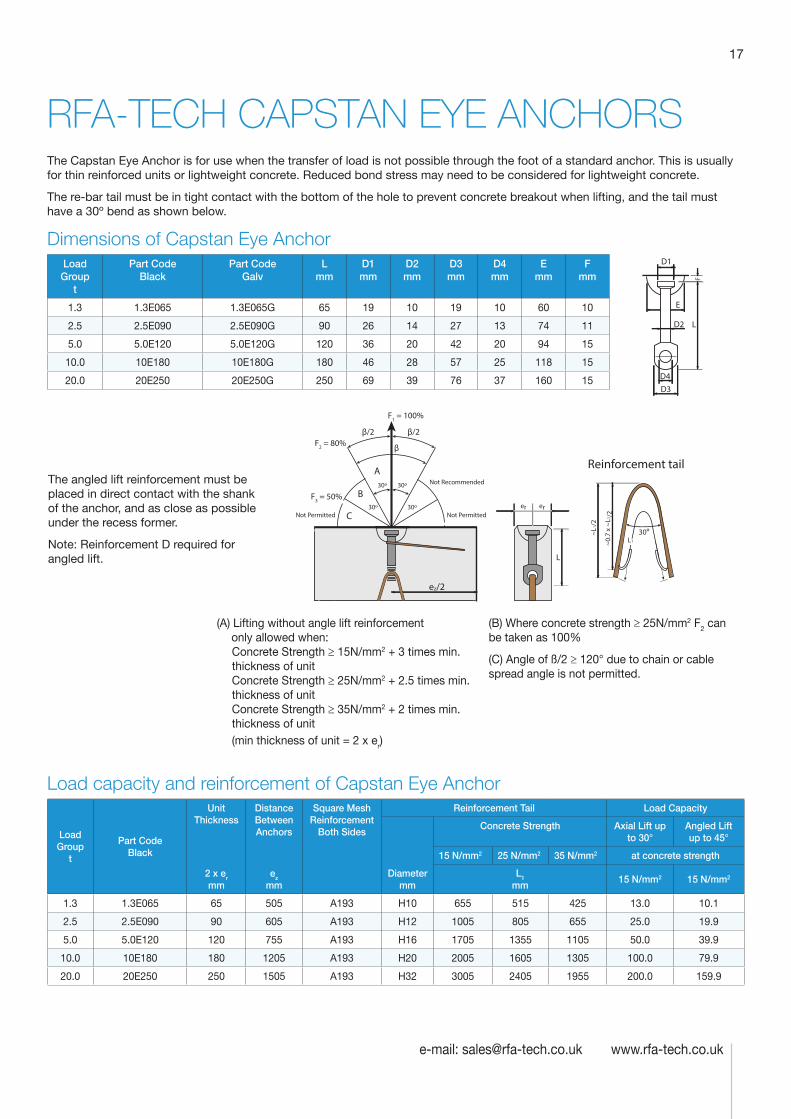
RFA-TECH CAPSTAN EYE ANCHORSThe Capstan Eye Anchor is for use when the transfer of load is not possible through the foot of a standard anchor. This is usually for thin reinforced units or lightweight concrete. Reduced bond stress may need to be considered for lightweight concrete.
The re-bar tail must be in tight contact with the bottom of the hole to prevent concrete breakout when lifting, and the tail must have a 30º bend as shown below.
Dimensions of Capstan Eye AnchorLoad Group
t
Part Code Black
Part Code Galv
L mm
D1 mm
D2 mm
D3 mm
D4 mm
E mm
F mm
1.3 1.3E065 1.3E065G 65 19 10 19 10 60 10
2.5 2.5E090 2.5E090G 90 26 14 27 13 74 11
5.0 5.0E120 5.0E120G 120 36 20 42 20 94 15
10.0 10E180 10E180G 180 46 28 57 25 118 15
20.0 20E250 20E250G 250 69 39 76 37 160 15
er er
ez/2
30ºL1~0
.7 x
~L1
/2
~L1/
2
Reinforcement tail
L
30º
30º
30º
30º
F1 = 100%
F2 = 80%
F3 = 50%
β/2
β
β/2
C
B
A
Not Permitted Not Permitted
Not Recommended
Load capacity and reinforcement of Capstan Eye Anchor
Load Group
t
Part Code Black
Unit Thickness
Distance Between Anchors
Square Mesh Reinforcement
Both Sides
Reinforcement Tail Load Capacity
Diameter mm
Concrete Strength Axial Lift up to 30°
Angled Lift up to 45°
2 x er mm
ez mm
15 N/mm2 25 N/mm2 35 N/mm2 at concrete strength
L1 mm
15 N/mm2 15 N/mm2
1.3 1.3E065 65 505 A193 H10 655 515 425 13.0 10.1
2.5 2.5E090 90 605 A193 H12 1005 805 655 25.0 19.9
5.0 5.0E120 120 755 A193 H16 1705 1355 1105 50.0 39.9
10.0 10E180 180 1205 A193 H20 2005 1605 1305 100.0 79.9
20.0 20E250 250 1505 A193 H32 3005 2405 1955 200.0 159.9
D1
E
D3
D2
F
D4
L
The angled lift reinforcement must be placed in direct contact with the shank of the anchor, and as close as possible under the recess former.
Note: Reinforcement D required for angled lift.
(A) Lifting without angle lift reinforcement only allowed when:
Concrete Strength ≥ 15N/mm2 + 3 times min. thickness of unitConcrete Strength ≥ 25N/mm2 + 2.5 times min. thickness of unitConcrete Strength ≥ 35N/mm2 + 2 times min. thickness of unit(min thickness of unit = 2 x er)
(B) Where concrete strength ≥ 25N/mm2 F2 can be taken as 100%
(C) Angle of ß/2 ≥ 120° due to chain or cable spread angle is not permitted.
Technical Product Data
Reinforcement
All reinforcement bar used in the Startabox system is of grade B500C conforming to BS4449. Startabox is available containing 8mm to 20mm reinforcement with 12mm and 16mm being the most commonly used sizes. The rebar material is specially selected to be suitable for rebending, a prerequisite of the system, and is cut and bent to meet the requirements of BS8666, specific requirements of CARES Appendix TA2 and in line with the CARES Technical Approval on the Startabox system.
All reinforcement used is tested regularly, both in-house and independently, to ensure it continues to meet the requirements of BS4449 once rebent, offering confidence to detailers and engineers and supported by relevant and recent testing data.
Case
Startabox cases are manufactured from galvanised mild steel sheet rolled to precise dimensions. The cases are fully perforated on all faces to provide an excellent bond to the first concrete pour and provide an efficient key for the subsequent pour. The cases are annealed at specific points along the case to ease nailing when fixing to formwork. A wide range of case sizes are available to suit the rebar detail requirement.
Lid Cover
The Startabox system is fitted with a plastic tear off lid, to allow easy removal once required. The plastic lid has the advantages of no sharp edges, low weight, minimal concrete adherence and is suitable for recycling. Where necessary or requested, steel lid covers can be fitted.
End Cap Seal
Startabox cases are fitted with two easily removable plastic end cap seals. These ensure the concrete cannot enter the casing. End cap seals are suitable for recycling once removed.
Telephone: 0870 011 2881
6
Curved Startbox
18
Telephone: 0870 011 2881
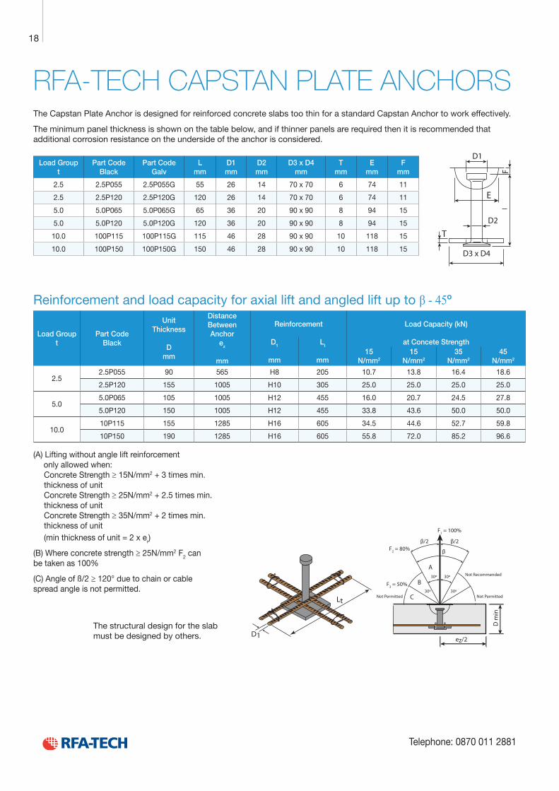
RFA-TECH CAPSTAN PLATE ANCHORSThe Capstan Plate Anchor is designed for reinforced concrete slabs too thin for a standard Capstan Anchor to work effectively.
The minimum panel thickness is shown on the table below, and if thinner panels are required then it is recommended that additional corrosion resistance on the underside of the anchor is considered.
Load Group t
Part Code Black
Part Code Galv
L mm
D1 mm
D2 mm
D3 x D4 mm
T mm
E mm
F mm
2.5 2.5P055 2.5P055G 55 26 14 70 x 70 6 74 11
2.5 2.5P120 2.5P120G 120 26 14 70 x 70 6 74 11
5.0 5.0P065 5.0P065G 65 36 20 90 x 90 8 94 15
5.0 5.0P120 5.0P120G 120 36 20 90 x 90 8 94 15
10.0 100P115 100P115G 115 46 28 90 x 90 10 118 15
10.0 100P150 100P150G 150 46 28 90 x 90 10 118 15
Reinforcement and load capacity for axial lift and angled lift up to β - 45º
Load Group t
Part Code Black
Unit Thickness
D
mm
Distance Between Anchor
ez
mm
Reinforcement Load Capacity (kN)
D1
mm
Lt
mm
at Concete Strength15
N/mm2
15 N/mm2
35 N/mm2
45 N/mm2
2.52.5P055 90 565 H8 205 10.7 13.8 16.4 18.6
2.5P120 155 1005 H10 305 25.0 25.0 25.0 25.0
5.05.0P065 105 1005 H12 455 16.0 20.7 24.5 27.8
5.0P120 150 1005 H12 455 33.8 43.6 50.0 50.0
10.010P115 155 1285 H16 605 34.5 44.6 52.7 59.8
10P150 190 1285 H16 605 55.8 72.0 85.2 96.6
(A) Lifting without angle lift reinforcement only allowed when:
Concrete Strength ≥ 15N/mm2 + 3 times min. thickness of unitConcrete Strength ≥ 25N/mm2 + 2.5 times min. thickness of unitConcrete Strength ≥ 35N/mm2 + 2 times min. thickness of unit(min thickness of unit = 2 x er)
(B) Where concrete strength ≥ 25N/mm2 F2 can be taken as 100%
(C) Angle of ß/2 ≥ 120° due to chain or cable spread angle is not permitted.
D1
D3 x D4
D2
E
F
T
D1
Lt
ez/2
D m
in
30º
30º
30º
30º
F1 = 100%
F2 = 80%
F3 = 50%
β/2
β
β/2
C
B
A
Not Permitted Not Permitted
Not Recommended
The structural design for the slab must be designed by others.
19
e-mail: [email protected] www.rfa-tech.co.uk
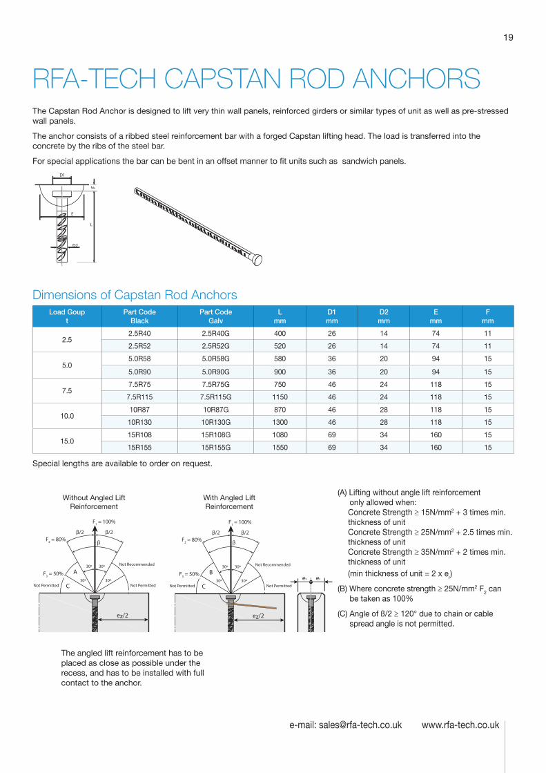
RFA-TECH CAPSTAN ROD ANCHORSThe Capstan Rod Anchor is designed to lift very thin wall panels, reinforced girders or similar types of unit as well as pre-stressed wall panels.
The anchor consists of a ribbed steel reinforcement bar with a forged Capstan lifting head. The load is transferred into the concrete by the ribs of the steel bar.
For special applications the bar can be bent in an offset manner to fit units such as sandwich panels.
D1
F
E
D2
L
Dimensions of Capstan Rod AnchorsLoad Goup
tPart Code
BlackPart Code
GalvL
mmD1 mm
D2 mm
E mm
F mm
2.52.5R40 2.5R40G 400 26 14 74 11
2.5R52 2.5R52G 520 26 14 74 11
5.05.0R58 5.0R58G 580 36 20 94 15
5.0R90 5.0R90G 900 36 20 94 15
7.57.5R75 7.5R75G 750 46 24 118 15
7.5R115 7.5R115G 1150 46 24 118 15
10.010R87 10R87G 870 46 28 118 15
10R130 10R130G 1300 46 28 118 15
15.015R108 15R108G 1080 69 34 160 15
15R155 15R155G 1550 69 34 160 15
Special lengths are available to order on request.
ez/2 ez/2
er er
30º
30º
30º
30º
F1 = 100%
F2 = 80%
F3 = 50%
β/2β/2
C
A
Not Permitted Not Permitted
Not Recommended 30º
30º
30º
30º
F1 = 100%
F2 = 80%
F3 = 50%
β/2
ββ
β/2
C
B
Not Permitted Not Permitted
Not Recommended
(A) Lifting without angle lift reinforcement only allowed when:
Concrete Strength ≥ 15N/mm2 + 3 times min. thickness of unitConcrete Strength ≥ 25N/mm2 + 2.5 times min. thickness of unitConcrete Strength ≥ 35N/mm2 + 2 times min. thickness of unit(min thickness of unit = 2 x er)
(B) Where concrete strength ≥ 25N/mm2 F2 can be taken as 100%
(C) Angle of ß/2 ≥ 120° due to chain or cable spread angle is not permitted.
The angled lift reinforcement has to be placed as close as possible under the recess, and has to be installed with full contact to the anchor.
Without Angled Lift Reinforcement
With Angled Lift Reinforcement
Technical Product Data
Reinforcement
All reinforcement bar used in the Startabox system is of grade B500C conforming to BS4449. Startabox is available containing 8mm to 20mm reinforcement with 12mm and 16mm being the most commonly used sizes. The rebar material is specially selected to be suitable for rebending, a prerequisite of the system, and is cut and bent to meet the requirements of BS8666, specific requirements of CARES Appendix TA2 and in line with the CARES Technical Approval on the Startabox system.
All reinforcement used is tested regularly, both in-house and independently, to ensure it continues to meet the requirements of BS4449 once rebent, offering confidence to detailers and engineers and supported by relevant and recent testing data.
Case
Startabox cases are manufactured from galvanised mild steel sheet rolled to precise dimensions. The cases are fully perforated on all faces to provide an excellent bond to the first concrete pour and provide an efficient key for the subsequent pour. The cases are annealed at specific points along the case to ease nailing when fixing to formwork. A wide range of case sizes are available to suit the rebar detail requirement.
Lid Cover
The Startabox system is fitted with a plastic tear off lid, to allow easy removal once required. The plastic lid has the advantages of no sharp edges, low weight, minimal concrete adherence and is suitable for recycling. Where necessary or requested, steel lid covers can be fitted.
End Cap Seal
Startabox cases are fitted with two easily removable plastic end cap seals. These ensure the concrete cannot enter the casing. End cap seals are suitable for recycling once removed.
Telephone: 0870 011 2881
6
Curved Startbox
20
Telephone: 0870 011 2881
REINFORCEMENT AND LOAD CAPACITIES FOR CAPSTAN ROD ANCHORS
e
Slot-in link, (positioned as close to anchor as possible)
ez/2
D2
Square mesh reinforcement
2
D
ß/2
B
A
B
D
er er
D
Edge reinforcement
Always insert angled lift linkopposite the direction of the load
Leng
th o
f slo
t-in
link
l tot
It1 = total length(approx. 2 x length of leg)Angled lift reinforcement
AID1
Reinforced area 3 times anchor length L
CD1
D3
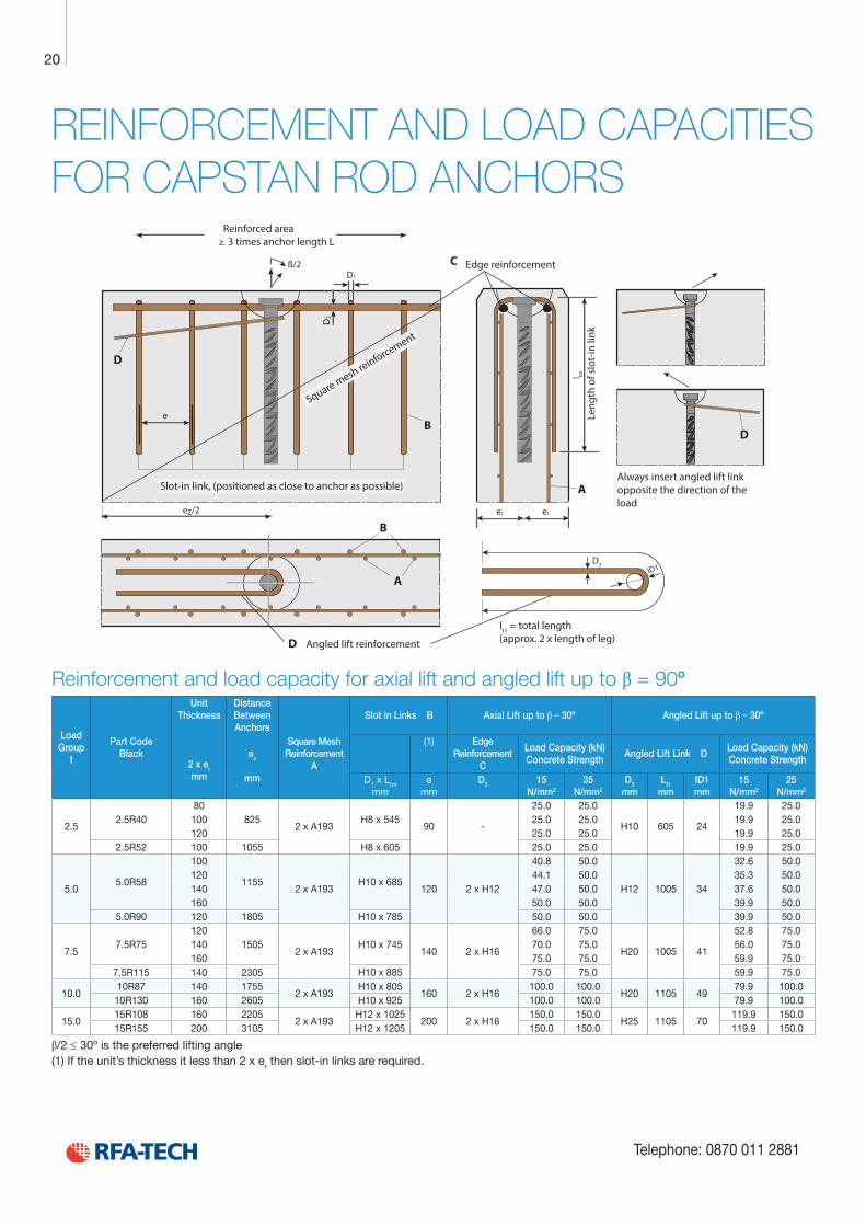
Reinforcement and load capacity for axial lift and angled lift up to β = 90º
Load Group
t
Part Code Black
Unit Thickness
2 x er mm
Distance Between Anchors
Square Mesh Reinforcement
A
Slot in Links B Axial Lift up to β = 30º
Angled Lift up to β = 30º
ez
mm
(1) Edge Reinforcement
C
Load Capacity (kN) Concrete Strength
Angled Lift Link DLoad Capacity (kN) Concrete Strength
D1 x Ltot mm
e mm
D2 15 N/mm2
35 N/mm2
D3 mm
Lt1 mm
ID1 mm
15 N/mm2
25 N/mm2
2.52.5R40
80825
2 x A193H8 x 545
90 -
25.0 25.0
H10 605 24
19.9 25.0100 25.0 25.0 19.9 25.0120 25.0 25.0 19.9 25.0
2.5R52 100 1055 H8 x 605 25.0 25.0 19.9 25.0
5.05.0R58
100
11552 x A193
H10 x 685120 2 x H12
40.8 50.0
H12 1005 34
32.6 50.0120 44.1 50.0 35.3 50.0140 47.0 50.0 37.6 50.0160 50.0 50.0 39.9 50.0
5.0R90 120 1805 H10 x 785 50.0 50.0 39.9 50.0
7.57.5R75
1201505
2 x A193H10 x 745
140 2 x H16
66.0 75.0
H20 1005 41
52.8 75.0140 70.0 75.0 56.0 75.0160 75.0 75.0 59.9 75.0
7.5R115 140 2305 H10 x 885 75.0 75.0 59.9 75.0
10.010R87 140 1755
2 x A193H10 x 805
160 2 x H16100.0 100.0
H20 1105 4979.9 100.0
10R130 160 2605 H10 x 925 100.0 100.0 79.9 100.0
15.015R108 160 2205
2 x A193H12 x 1025
200 2 x H16150.0 150.0
H25 1105 70119.9 150.0
15R155 200 3105 H12 x 1205 150.0 150.0 119.9 150.0
β/2 ≤ 30º is the preferred lifting angle (1) If the unit’s thickness it less than 2 x er then slot-in links are required.
21
e-mail: [email protected] www.rfa-tech.co.uk
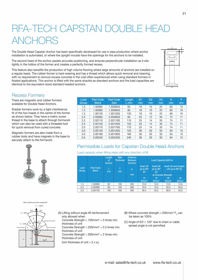
RFA-TECH CAPSTAN DOUBLE HEAD ANCHORS
(A) Lifting without angle lift reinforcement only allowed when:
Concrete Strength ≥ 15N/mm2 + 3 times min. thickness of unitConcrete Strength ≥ 25N/mm2 + 2.5 times min. thickness of unitConcrete Strength ≥ 35N/mm2 + 2 times min. thickness of unit(min thickness of unit = 2 x er)
(B) Where concrete strength ≥ 25N/mm2 F2 can be taken as 100%
(C) Angle of ß/2 ≥ 120° due to chain or cable spread angle is not permitted.
Load Group
Part Code Black
Part Code Galv
Length L mm
D1 mm
D2 mm
D3 mm
E mm
F mm
1.3 1.3D065 1.3D065G 65 18 10 25 60 101.3 1.3D085 1.3D085G 85 18 10 25 60 101.3 1.3D120 1.3D120G 120 18 10 25 60 102.5 2.5D065 2.5D065G 65 25 14 35 74 112.5 2.5D110 2.5D110G 110 25 14 35 74 112.5 2.5D120 2.5D120G 120 25 14 35 74 112.5 2.5D170 2.5D170G 170 25 14 35 74 115.0 5.0D120 5.0D120G 120 36 20 50 94 155.0 5.0D180 5.0D180G 180 36 20 50 94 155.0 5.0D240 5.0D240G 240 36 20 50 94 15
Permissible Loads for Capstan Double Head AnchorsLoad capacity when lifting slabs with any direction of lift
Load Group
Part Code Black
Length of
Anchor L
mm
Slab Thickness
T
mm
Distance Between Anchors
Load Capacity (kN) for
ez
mm
Axial Lift up to 60º
[β]
Axial Lift up to 90º
[β]
Axial Lift and Angled Lift up to 90º [β]
at Concete Strength15
N/mm2
15 N/mm2
25 N/mm2
35 N/mm2
1.3 1.3D065 65 100 305 13.0 10.3 13.0 13.02.5 2.5D085 85 120 385 19.4 15.5 25.0 25.05.0 5.0D120 120 160 505 29.4 23.5 38.0 45.0
D3
L
D1
D2
F
E
Recess FormersThere are magnetic and rubber formers available for Double Head Anchors.
Rubber formers work by a tight interference fit of the two heads in the centre of the former as shown below. They have a metric screw thread in the base to attach through formwork which can also be used with a threaded tool for quick removal from cured concrete.
Magnetic formers are also made from a rubber body and have magnets in the base to securely attach to the formwork.
ez/2
LT
With reinforcement for angled lift
30º
30º
30º
30º
F1 = 100%
F2 = 80%
F3 = 50%
β/2
β
β/2
C
B
A
Not Permitted Not Permitted
Not Recommended
The Double Head Capstan Anchor has been specifically developed for use in pipe production where anchor installation is automated, or where the upright moulds have the openings for the anchors to be installed.
The second head of the anchor assists accurate positioning, and ensures perpendicular installation as it sits tightly in the hollow of the former and creates a perfectly formed recess.
This feature also benefits the production of high volume flooring where large amounts of anchors are installed on a regular basis. The rubber former is hard wearing and has a thread which allows quick removal and cleaning, with no requirement to remove excess concrete in the void often experienced when using standard formers in floated applications. This anchor is lifted with the same shackle as standard anchors and the load capacities are identical to the equivalent sized standard headed anchors.
Technical Product Data
Reinforcement
All reinforcement bar used in the Startabox system is of grade B500C conforming to BS4449. Startabox is available containing 8mm to 20mm reinforcement with 12mm and 16mm being the most commonly used sizes. The rebar material is specially selected to be suitable for rebending, a prerequisite of the system, and is cut and bent to meet the requirements of BS8666, specific requirements of CARES Appendix TA2 and in line with the CARES Technical Approval on the Startabox system.
All reinforcement used is tested regularly, both in-house and independently, to ensure it continues to meet the requirements of BS4449 once rebent, offering confidence to detailers and engineers and supported by relevant and recent testing data.
Case
Startabox cases are manufactured from galvanised mild steel sheet rolled to precise dimensions. The cases are fully perforated on all faces to provide an excellent bond to the first concrete pour and provide an efficient key for the subsequent pour. The cases are annealed at specific points along the case to ease nailing when fixing to formwork. A wide range of case sizes are available to suit the rebar detail requirement.
Lid Cover
The Startabox system is fitted with a plastic tear off lid, to allow easy removal once required. The plastic lid has the advantages of no sharp edges, low weight, minimal concrete adherence and is suitable for recycling. Where necessary or requested, steel lid covers can be fitted.
End Cap Seal
Startabox cases are fitted with two easily removable plastic end cap seals. These ensure the concrete cannot enter the casing. End cap seals are suitable for recycling once removed.
Telephone: 0870 011 2881
6
Curved Startbox
22
Telephone: 0870 011 2881
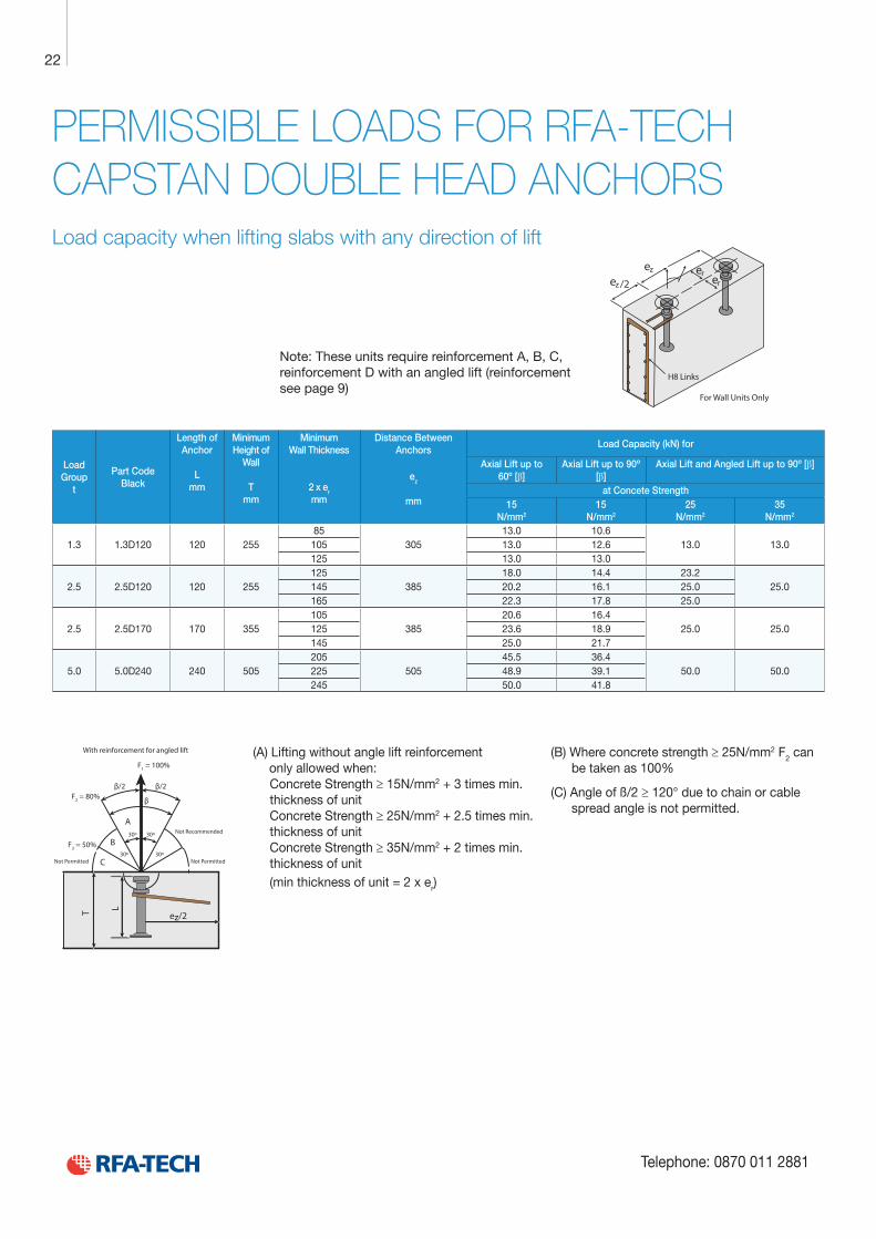
PERMISSIBLE LOADS FOR RFA-TECH CAPSTAN DOUBLE HEAD ANCHORSLoad capacity when lifting slabs with any direction of lift
For Wall Units Only
H8 Links
Note: These units require reinforcement A, B, C, reinforcement D with an angled lift (reinforcement see page 9)
(A) Lifting without angle lift reinforcement only allowed when:
Concrete Strength ≥ 15N/mm2 + 3 times min. thickness of unitConcrete Strength ≥ 25N/mm2 + 2.5 times min. thickness of unitConcrete Strength ≥ 35N/mm2 + 2 times min. thickness of unit(min thickness of unit = 2 x er)
(B) Where concrete strength ≥ 25N/mm2 F2 can be taken as 100%
(C) Angle of ß/2 ≥ 120° due to chain or cable spread angle is not permitted.
Load Group
t
Part Code Black
Length of Anchor
L
mm
Minimum Height of
Wall
T mm
Minimum Wall Thickness
2 x er mm
Distance Between Anchors
Load Capacity (kN) for
ez
mm
Axial Lift up to 60º [β]
Axial Lift up to 90º [β]
Axial Lift and Angled Lift up to 90º [β]
at Concete Strength15
N/mm2
15 N/mm2
25 N/mm2
35 N/mm2
1.3 1.3D120 120 25585
30513.0 10.6
13.0 13.0105 13.0 12.6125 13.0 13.0
2.5 2.5D120 120 255125
38518.0 14.4 23.2
25.0145 20.2 16.1 25.0165 22.3 17.8 25.0
2.5 2.5D170 170 355105
38520.6 16.4
25.0 25.0125 23.6 18.9145 25.0 21.7
5.0 5.0D240 240 505205
50545.5 36.4
50.0 50.0225 48.9 39.1245 50.0 41.8
ez/2
LT
With reinforcement for angled lift
30º
30º
30º
30º
F1 = 100%
F2 = 80%
F3 = 50%
β/2
β
β/2
C
B
A
Not Permitted Not Permitted
Not Recommended
23
e-mail: [email protected] www.rfa-tech.co.uk
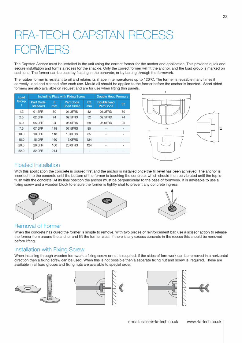
RFA-TECH CAPSTAN RECESS FORMERSThe Capstan Anchor must be installed in the unit using the correct former for the anchor and application. This provides quick and secure installation and forms a recess for the shackle. Only the correct former will fit the anchor, and the load group is marked on each one. The former can be used by floating in the concrete, or by bolting through the formwork.
The rubber former is resistant to oil and retains its shape in temperatures up to 120ºC. The former is reusable many times if correctly used and cleaned after each use. Mould oil should be applied to the former before the anchor is inserted. Short sided formers are also available on request and are for use when lifting thin panels.
Load Group
t
Including Plate with Fixing Screw Double Head Formers
Part Code Standard
E mm
Part Code Short Sided
E2 mm
Doublehead Part Code
E3
1.3 01.3FR 60 01.3FRS 42 01.3FRD 60
2.5 02.5FR 74 02.5FRS 52 02.5FRD 74
5.0 05.0FR 94 05.0FRS 69 05.0FRD 95
7.5 07.5FR 118 07.5FRS 85 - -
10.0 10.0FR 118 10.0FRS 85 - -
15.0 15.0FR 160 15.0FRS 124 - -
20.0 20.0FR 160 20.0FRS 124 - -
32.0 32.0FR 214 - - - -
Floated InstallationWith this application the concrete is poured first and the anchor is installed once the fill level has been achieved. The anchor is inserted into the concrete until the bottom of the former is touching the concrete, which should then be vibrated until the top is flush with the concrete. At its final position the anchor must be perpendicular to the base of formwork. It is advisable to use a fixing screw and a wooden block to ensure the former is tightly shut to prevent any concrete ingress.
RFA
25
RFA
25
Removal of FormerWhen the concrete has cured the former is simple to remove. With two pieces of reinforcement bar, use a scissor action to release the former from around the anchor and lift the former clear. If there is any excess concrete in the recess this should be removed before lifting.
Installation with Fixing ScrewWhen installing through wooden formwork a fixing screw or nut is required. If the sides of formwork can be removed in a horizontal direction then a fixing screw can be used. When this is not possible then a separate fixing nut and screw is required. These are available in all load groups and fixing nuts are available to special order.
E
E2 E3
Technical Product Data
Reinforcement
All reinforcement bar used in the Startabox system is of grade B500C conforming to BS4449. Startabox is available containing 8mm to 20mm reinforcement with 12mm and 16mm being the most commonly used sizes. The rebar material is specially selected to be suitable for rebending, a prerequisite of the system, and is cut and bent to meet the requirements of BS8666, specific requirements of CARES Appendix TA2 and in line with the CARES Technical Approval on the Startabox system.
All reinforcement used is tested regularly, both in-house and independently, to ensure it continues to meet the requirements of BS4449 once rebent, offering confidence to detailers and engineers and supported by relevant and recent testing data.
Case
Startabox cases are manufactured from galvanised mild steel sheet rolled to precise dimensions. The cases are fully perforated on all faces to provide an excellent bond to the first concrete pour and provide an efficient key for the subsequent pour. The cases are annealed at specific points along the case to ease nailing when fixing to formwork. A wide range of case sizes are available to suit the rebar detail requirement.
Lid Cover
The Startabox system is fitted with a plastic tear off lid, to allow easy removal once required. The plastic lid has the advantages of no sharp edges, low weight, minimal concrete adherence and is suitable for recycling. Where necessary or requested, steel lid covers can be fitted.
End Cap Seal
Startabox cases are fitted with two easily removable plastic end cap seals. These ensure the concrete cannot enter the casing. End cap seals are suitable for recycling once removed.
Telephone: 0870 011 2881
6
Curved Startbox
24
Telephone: 0870 011 2881
RFA-TECH MAGNETIC RECESS FORMERSThe Capstan Anchor can be installed in metal moulds by the use of magnetic formers. These are used where the lifting anchors are not accessible when casting. They are available in load groups from 1.3t to 10.0t. All magnetic formers are zinc plated for corrosion resistance or made with a rubber coating.
Load Group t
Metal Magnet Part Code
AdhesionRubber Sleeve
Part CodeRubber Magnet
Part CodeAdhesion
1.3 1.3MFR 170kpi 1.3MFRS 1.3MFRR 110kpi
2.5 2.5MFR 265kpi 2.5MFRS 2.5MFRR 185kpi
5.0 5.0MFR 470kpi 5.0MFRS 5.0MFRR 160kpi
7.5/10.0 10.0MFR 600kpi7.5MFRS - -
10.0MFRS - -
Using Magnetic FormersThe magnetic adhesion holds the former onto the metal formwork with sufficient strength to prevent any movement when pouring concrete. The anchor is then placed in the centre of the former and the rubber sleeve put around the shank and pushed into the void, holding it tightly in position as shown below. The former and sleeve should be coated in mould oil before casting. When the unit is struck the former remains on the mould with the anchor and sleeve coming away with the unit. The sleeve should then be removed and cleaned for re-use.
When installing with magnetic formers, particularly when the anchors are horizontal to the formwork, provisions should be made to ensure they remain fixed during pouring. This can be done by tying the anchor to the formwork or by using spacers.
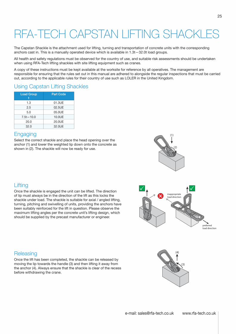
25
e-mail: [email protected] www.rfa-tech.co.uk
RFA-TECH CAPSTAN LIFTING SHACKLESThe Capstan Shackle is the attachment used for lifting, turning and transportation of concrete units with the corresponding anchors cast in. This is a manually operated device which is available in 1.3t—32.0t load groups.
All health and safety regulations must be observed for the country of use, and suitable risk assessments should be undertaken when using RFA-Tech lifting shackles with site lifting equipment such as cranes.
A copy of these instructions must be kept available at the worksite for reference by all operatives. The management are responsible for ensuring that the rules set out in this manual are adhered to alongside the regular inspections that must be carried out, according to the applicable rules for their country of use such as LOLER in the United Kingdom.
Using Capstan Lifting ShacklesLoad Group
tPart Code
1.3 01.3UE
2.5 02.5UE
5.0 05.0UE
7.5t—10.0 10.0UE
20.0 20.0UE
32.0 32.0UE
EngagingSelect the correct shackle and place the head opening over the anchor (1) and lower the weighted lip down onto the concrete as shown in (2). The shackle will now be ready for use.
LiftingOnce the shackle is engaged the unit can be lifted. The direction of lip must always be in the direction of the lift as this locks the shackle under load. The shackle is suitable for axial / angled lifting, turning, pitching and swivelling of units, providing the anchors have been suitably reinforced for the lift in question. Please observe the maximum lifting angles per the concrete unit’s lifting design, which should be supplied by the precast manufacturer or engineer.
ReleasingOnce the lift has been completed, the shackle can be released by moving the lip towards the handle (3) and then lifting it away from the anchor (4). Always ensure that the shackle is clear of the recess before withdrawing the crane.
(1)
(2)
inappropriate
load direction
preferred load direction
(3)
(4)
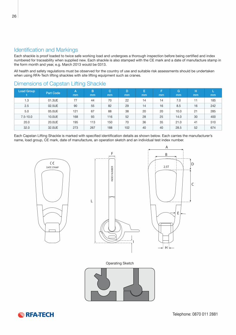
Technical Product Data
Reinforcement
All reinforcement bar used in the Startabox system is of grade B500C conforming to BS4449. Startabox is available containing 8mm to 20mm reinforcement with 12mm and 16mm being the most commonly used sizes. The rebar material is specially selected to be suitable for rebending, a prerequisite of the system, and is cut and bent to meet the requirements of BS8666, specific requirements of CARES Appendix TA2 and in line with the CARES Technical Approval on the Startabox system.
All reinforcement used is tested regularly, both in-house and independently, to ensure it continues to meet the requirements of BS4449 once rebent, offering confidence to detailers and engineers and supported by relevant and recent testing data.
Case
Startabox cases are manufactured from galvanised mild steel sheet rolled to precise dimensions. The cases are fully perforated on all faces to provide an excellent bond to the first concrete pour and provide an efficient key for the subsequent pour. The cases are annealed at specific points along the case to ease nailing when fixing to formwork. A wide range of case sizes are available to suit the rebar detail requirement.
Lid Cover
The Startabox system is fitted with a plastic tear off lid, to allow easy removal once required. The plastic lid has the advantages of no sharp edges, low weight, minimal concrete adherence and is suitable for recycling. Where necessary or requested, steel lid covers can be fitted.
End Cap Seal
Startabox cases are fitted with two easily removable plastic end cap seals. These ensure the concrete cannot enter the casing. End cap seals are suitable for recycling once removed.
Telephone: 0870 011 2881
6
Curved Startbox
26
Telephone: 0870 011 2881
Identification and MarkingsEach shackle is proof loaded to twice safe working load and undergoes a thorough inspection before being certified and index numbered for traceability when supplied new. Each shackle is also stamped with the CE mark and a date of manufacture stamp in the form month and year, e.g. March 2013 would be 0313.
All health and safety regulations must be observed for the country of use and suitable risk assessments should be undertaken when using RFA-Tech lifting shackles with site lifting equipment such as cranes.
Dimensions of Capstan Lifting ShackleLoad Group
tPart Code
A mm
B mm
C mm
D mm
E mm
F mm
G mm
H mm
L mm
1.3 01.3UE 77 44 70 22 14 14 7.0 11 185
2.5 02.5UE 90 55 82 29 14 16 8.5 16 242
5.0 05.0UE 121 67 88 38 20 20 10.0 21 285
7.5-10.0 10.0UE 168 93 116 52 28 25 14.0 30 400
20.0 20.0UE 195 113 150 70 36 35 21.0 41 510
32.0 32.0UE 273 267 188 102 40 40 28.5 52 674
Each Capstan Lifting Shackle is marked with specified identification details as shown below. Each carries the manufacturer’s name, load group, CE mark, date of manufacture, an operation sketch and an individual test index number.
2.5T
E
C
D
B
A
H
DATE STAMP
F
L
I
IND
EX N
UM
BER
Operating Sketch
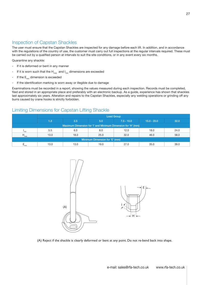
27
e-mail: [email protected] www.rfa-tech.co.uk
Inspection of Capstan ShacklesThe user must ensure that the Capstan Shackles are inspected for any damage before each lift. In addition, and in accordance with the regulations of the country of use, the customer must carry out full inspections at the regular intervals required. These must be carried out by a qualified person at intervals to suit the site conditions, or in any event every six months.
Quarantine any shackle:
- If it is deformed or bent in any manner
- If it is worn such that the Hmax and Imin dimensions are exceeded
- If the Emin dimension is exceeded
- If the identification marking is worn away or illegible due to damage
Examinations must be recorded in a report, showing the values measured during each inspection. Records must be completed, filed and stored in an appropriate place and preferably with an electronic backup. As a guide, experience has shown that shackles last approximately six years. Alteration and repairs to the Capstan Shackles, especially any welding operations or grinding off any burrs caused by crane hooks is strictly forbidden.
Limiting Dimensions for Capstan Lifting ShackleLoad Group
1.3 2.5 5.0 7.5 - 10.0 15.0 - 20.0 32.0
Maximum Dimension for ‘I’ and Minimum Dimension for ‘H’ (mm)
Imin 5.5 6.0 8.0 12.0 18.0 24.0
Hmax 13.0 18.0 25.0 32.0 46.0 58.0
Minimum Dimension for ‘E’ (mm)
Emin 13.0 13.0 19.0 27.0 35.0 39.0
H
E
I
(A) Reject if the shackle is clearly deformed or bent at any point. Do not re-bend back into shape.
(A)
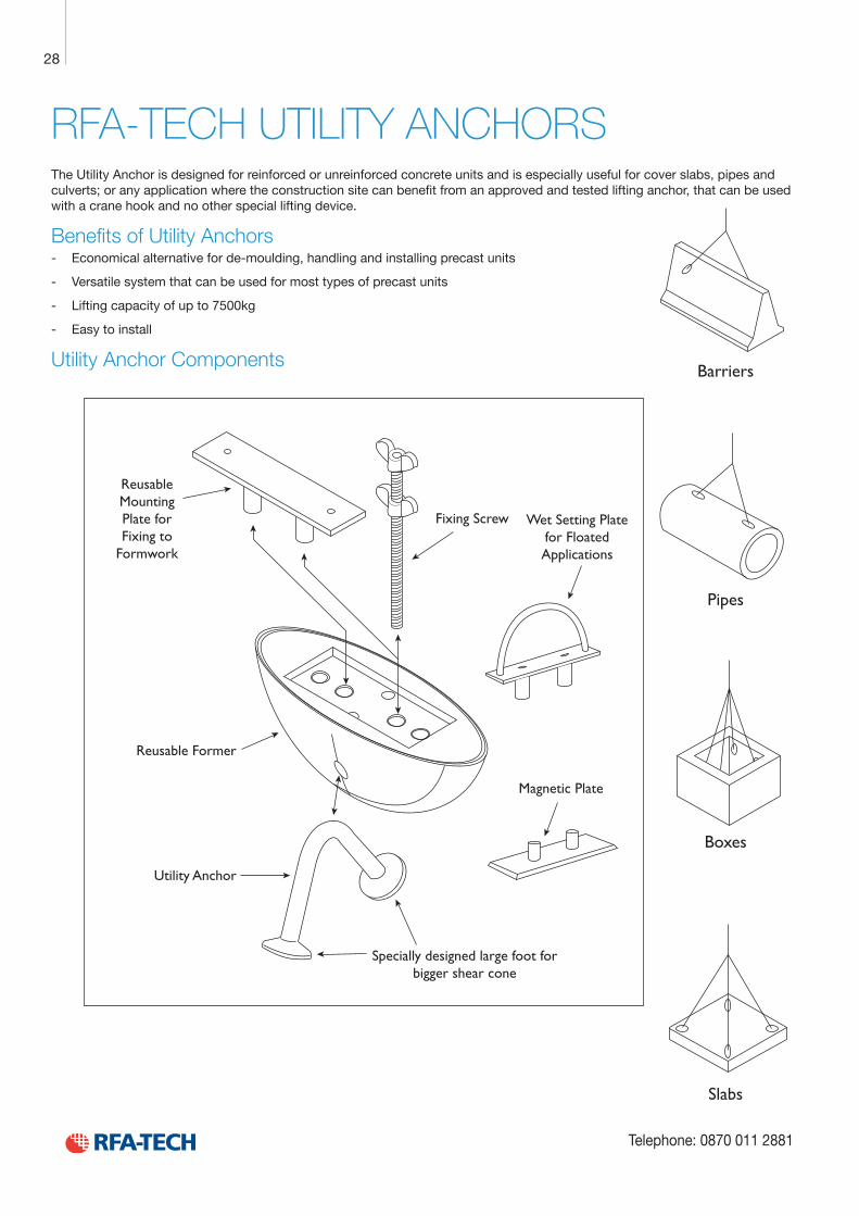
Technical Product Data
Reinforcement
All reinforcement bar used in the Startabox system is of grade B500C conforming to BS4449. Startabox is available containing 8mm to 20mm reinforcement with 12mm and 16mm being the most commonly used sizes. The rebar material is specially selected to be suitable for rebending, a prerequisite of the system, and is cut and bent to meet the requirements of BS8666, specific requirements of CARES Appendix TA2 and in line with the CARES Technical Approval on the Startabox system.
All reinforcement used is tested regularly, both in-house and independently, to ensure it continues to meet the requirements of BS4449 once rebent, offering confidence to detailers and engineers and supported by relevant and recent testing data.
Case
Startabox cases are manufactured from galvanised mild steel sheet rolled to precise dimensions. The cases are fully perforated on all faces to provide an excellent bond to the first concrete pour and provide an efficient key for the subsequent pour. The cases are annealed at specific points along the case to ease nailing when fixing to formwork. A wide range of case sizes are available to suit the rebar detail requirement.
Lid Cover
The Startabox system is fitted with a plastic tear off lid, to allow easy removal once required. The plastic lid has the advantages of no sharp edges, low weight, minimal concrete adherence and is suitable for recycling. Where necessary or requested, steel lid covers can be fitted.
End Cap Seal
Startabox cases are fitted with two easily removable plastic end cap seals. These ensure the concrete cannot enter the casing. End cap seals are suitable for recycling once removed.
Telephone: 0870 011 2881
6
Curved Startbox
28
Telephone: 0870 011 2881
RFA-TECH UTILITY ANCHORS The Utility Anchor is designed for reinforced or unreinforced concrete units and is especially useful for cover slabs, pipes and culverts; or any application where the construction site can benefit from an approved and tested lifting anchor, that can be used with a crane hook and no other special lifting device.
Benefits of Utility Anchors - Economical alternative for de-moulding, handling and installing precast units
- Versatile system that can be used for most types of precast units
- Lifting capacity of up to 7500kg
- Easy to install
Utility Anchor ComponentsBarriers
Pipes
Boxes
Slabs
Utility Anchor
Specially designed large foot forbigger shear cone
Reusable Former
ReusableMountingPlate for Fixing to
Formwork
Fixing Screw Wet Setting Platefor Floated Applications
Magnetic Plate
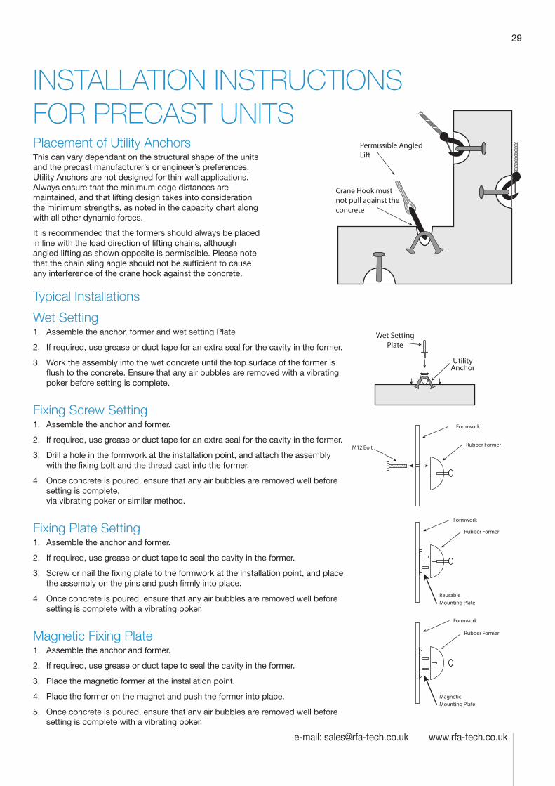
29
e-mail: [email protected] www.rfa-tech.co.uk
INSTALLATION INSTRUCTIONS FOR PRECAST UNITS
Formwork
Rubber Former
Formwork
Rubber Former
ReusableMounting Plate
M12 Bolt
SteelPlate
UtilityAnchor
Permissible Angled Lift
Crane Hook must not pull against the concrete
Formwork
Rubber Former
MagneticMounting Plate
Wet Setting Plate
Wet Setting1. Assemble the anchor, former and wet setting Plate
2. If required, use grease or duct tape for an extra seal for the cavity in the former.
3. Work the assembly into the wet concrete until the top surface of the former is flush to the concrete. Ensure that any air bubbles are removed with a vibrating poker before setting is complete.
Fixing Screw Setting1. Assemble the anchor and former.
2. If required, use grease or duct tape for an extra seal for the cavity in the former.
3. Drill a hole in the formwork at the installation point, and attach the assembly with the fixing bolt and the thread cast into the former.
4. Once concrete is poured, ensure that any air bubbles are removed well before setting is complete, via vibrating poker or similar method.
Fixing Plate Setting1. Assemble the anchor and former.
2. If required, use grease or duct tape to seal the cavity in the former.
3. Screw or nail the fixing plate to the formwork at the installation point, and place the assembly on the pins and push firmly into place.
4. Once concrete is poured, ensure that any air bubbles are removed well before setting is complete with a vibrating poker.
Magnetic Fixing Plate1. Assemble the anchor and former.
2. If required, use grease or duct tape to seal the cavity in the former.
3. Place the magnetic former at the installation point.
4. Place the former on the magnet and push the former into place.
5. Once concrete is poured, ensure that any air bubbles are removed well before setting is complete with a vibrating poker.
Typical Installations
Placement of Utility AnchorsThis can vary dependant on the structural shape of the units and the precast manufacturer’s or engineer’s preferences. Utility Anchors are not designed for thin wall applications. Always ensure that the minimum edge distances are maintained, and that lifting design takes into consideration the minimum strengths, as noted in the capacity chart along with all other dynamic forces.
It is recommended that the formers should always be placed in line with the load direction of lifting chains, although angled lifting as shown opposite is permissible. Please note that the chain sling angle should not be sufficient to cause any interference of the crane hook against the concrete.
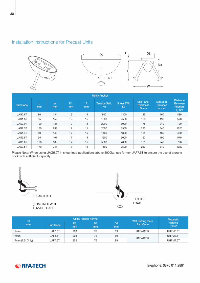
Technical Product Data
Reinforcement
All reinforcement bar used in the Startabox system is of grade B500C conforming to BS4449. Startabox is available containing 8mm to 20mm reinforcement with 12mm and 16mm being the most commonly used sizes. The rebar material is specially selected to be suitable for rebending, a prerequisite of the system, and is cut and bent to meet the requirements of BS8666, specific requirements of CARES Appendix TA2 and in line with the CARES Technical Approval on the Startabox system.
All reinforcement used is tested regularly, both in-house and independently, to ensure it continues to meet the requirements of BS4449 once rebent, offering confidence to detailers and engineers and supported by relevant and recent testing data.
Case
Startabox cases are manufactured from galvanised mild steel sheet rolled to precise dimensions. The cases are fully perforated on all faces to provide an excellent bond to the first concrete pour and provide an efficient key for the subsequent pour. The cases are annealed at specific points along the case to ease nailing when fixing to formwork. A wide range of case sizes are available to suit the rebar detail requirement.
Lid Cover
The Startabox system is fitted with a plastic tear off lid, to allow easy removal once required. The plastic lid has the advantages of no sharp edges, low weight, minimal concrete adherence and is suitable for recycling. Where necessary or requested, steel lid covers can be fitted.
End Cap Seal
Startabox cases are fitted with two easily removable plastic end cap seals. These ensure the concrete cannot enter the casing. End cap seals are suitable for recycling once removed.
Telephone: 0870 011 2881
6
Curved Startbox
30
Telephone: 0870 011 2881
Installation Instructions for Precast Units
D1
D2
W
L
D4
D3F
Utility Anchor
Part CodeL
mmW
mmD1 mm
F mm
Tension SWL Kg
Shear SWL Kg
Min Panel Thickness
D mm
Min Edge Distance
er mm
Distance Between Anchors er mm
UAG0.8T 80 134 12 15 800 1300 135 160 480
UAG1.8T 95 152 12 15 1800 2500 150 190 570
UAG2.0T 120 181 12 15 2000 3000 175 240 720
UAG2.5T 170 238 12 15 2500 3500 225 340 1020
UAG1.4T 80 143 17 15 1400 1800 135 160 480
UAG3.5T 95 161 17 15 3500 5000 150 190 570
UAG5.0T 120 189 17 15 5000 7000 175 240 720
UAG7.5T 170 247 17 15 7500 7500 230 340 1020
Please Note: When using UAG5.0T in shear load applications above 5000kg, use former UAF7.5T to ensure the use of a crane hook with sufficient capacity.
SHEAR LOAD
(COMBINED WITHTENSILE LOAD)
TENSILELOAD
D1 mm
Utility Anchor FormerWet Setting Plate
Part Code
Magnetic Holding PlatesPart Code
D2 mm
D3 mm
D4 mm
12mm UAF0.8T 203 76 89 UAFWSP12 UHPM0.8T
17mm UAF3.5T 203 76 89UAFWSP17
UHPM3.5T
17mm (7.5t Only) UAF7.5T 252 76 89 UHPM7.5T
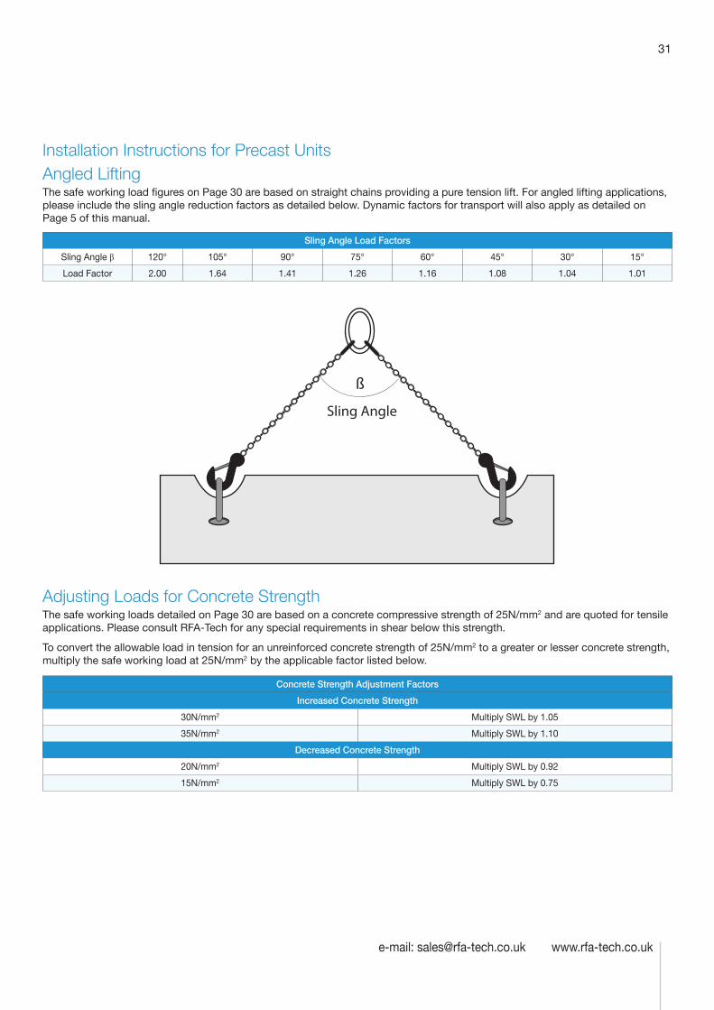
31
e-mail: [email protected] www.rfa-tech.co.uk
Installation Instructions for Precast UnitsAngled LiftingThe safe working load figures on Page 30 are based on straight chains providing a pure tension lift. For angled lifting applications, please include the sling angle reduction factors as detailed below. Dynamic factors for transport will also apply as detailed on Page 5 of this manual.
Sling Angle Load Factors
Sling Angle β 120° 105° 90° 75° 60° 45° 30° 15°
Load Factor 2.00 1.64 1.41 1.26 1.16 1.08 1.04 1.01
Sling Angle
ß
Adjusting Loads for Concrete StrengthThe safe working loads detailed on Page 30 are based on a concrete compressive strength of 25N/mm2 and are quoted for tensile applications. Please consult RFA-Tech for any special requirements in shear below this strength.
To convert the allowable load in tension for an unreinforced concrete strength of 25N/mm2 to a greater or lesser concrete strength, multiply the safe working load at 25N/mm2 by the applicable factor listed below.
Concrete Strength Adjustment Factors
Increased Concrete Strength
30N/mm2 Multiply SWL by 1.05
35N/mm2 Multiply SWL by 1.10
Decreased Concrete Strength
20N/mm2 Multiply SWL by 0.92
15N/mm2 Multiply SWL by 0.75
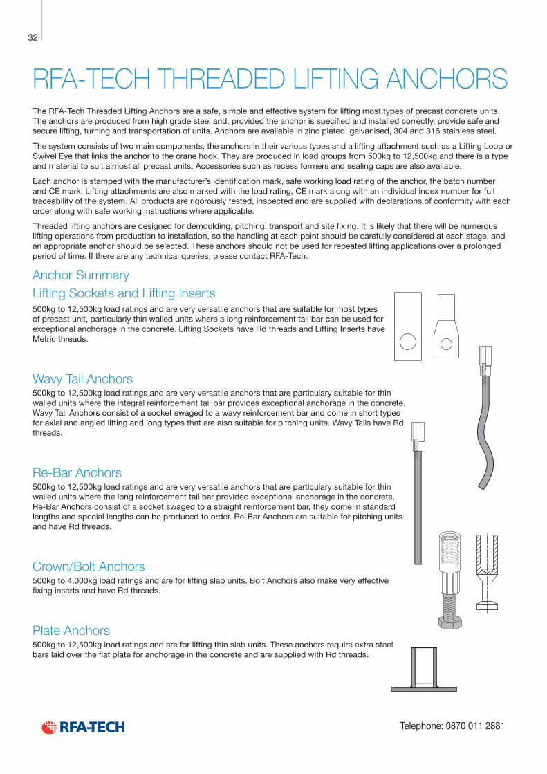
Technical Product Data
Reinforcement
All reinforcement bar used in the Startabox system is of grade B500C conforming to BS4449. Startabox is available containing 8mm to 20mm reinforcement with 12mm and 16mm being the most commonly used sizes. The rebar material is specially selected to be suitable for rebending, a prerequisite of the system, and is cut and bent to meet the requirements of BS8666, specific requirements of CARES Appendix TA2 and in line with the CARES Technical Approval on the Startabox system.
All reinforcement used is tested regularly, both in-house and independently, to ensure it continues to meet the requirements of BS4449 once rebent, offering confidence to detailers and engineers and supported by relevant and recent testing data.
Case
Startabox cases are manufactured from galvanised mild steel sheet rolled to precise dimensions. The cases are fully perforated on all faces to provide an excellent bond to the first concrete pour and provide an efficient key for the subsequent pour. The cases are annealed at specific points along the case to ease nailing when fixing to formwork. A wide range of case sizes are available to suit the rebar detail requirement.
Lid Cover
The Startabox system is fitted with a plastic tear off lid, to allow easy removal once required. The plastic lid has the advantages of no sharp edges, low weight, minimal concrete adherence and is suitable for recycling. Where necessary or requested, steel lid covers can be fitted.
End Cap Seal
Startabox cases are fitted with two easily removable plastic end cap seals. These ensure the concrete cannot enter the casing. End cap seals are suitable for recycling once removed.
Telephone: 0870 011 2881
6
Curved Startbox
32
Telephone: 0870 011 2881
RFA-TECH THREADED LIFTING ANCHORSThe RFA-Tech Threaded Lifting Anchors are a safe, simple and effective system for lifting most types of precast concrete units. The anchors are produced from high grade steel and, provided the anchor is specified and installed correctly, provide safe and secure lifting, turning and transportation of units. Anchors are available in zinc plated, galvanised, 304 and 316 stainless steel.
The system consists of two main components, the anchors in their various types and a lifting attachment such as a Lifting Loop or Swivel Eye that links the anchor to the crane hook. They are produced in load groups from 500kg to 12,500kg and there is a type and material to suit almost all precast units. Accessories such as recess formers and sealing caps are also available.
Each anchor is stamped with the manufacturer’s identification mark, safe working load rating of the anchor, the batch number and CE mark. Lifting attachments are also marked with the load rating, CE mark along with an individual index number for full traceability of the system. All products are rigorously tested, inspected and are supplied with declarations of conformity with each order along with safe working instructions where applicable.
Threaded lifting anchors are designed for demoulding, pitching, transport and site fixing. It is likely that there will be numerous lifting operations from production to installation, so the handling at each point should be carefully considered at each stage, and an appropriate anchor should be selected. These anchors should not be used for repeated lifting applications over a prolonged period of time. If there are any technical queries, please contact RFA-Tech.
Anchor SummaryLifting Sockets and Lifting Inserts500kg to 12,500kg load ratings and are very versatile anchors that are suitable for most types of precast unit, particularly thin walled units where a long reinforcement tail bar can be used for exceptional anchorage in the concrete. Lifting Sockets have Rd threads and Lifting Inserts have Metric threads.
Wavy Tail Anchors500kg to 12,500kg load ratings and are very versatile anchors that are particulary suitable for thin walled units where the integral reinforcement tail bar provides exceptional anchorage in the concrete. Wavy Tail Anchors consist of a socket swaged to a wavy reinforcement bar and come in short types for axial and angled lifting and long types that are also suitable for pitching units. Wavy Tails have Rd threads.
Re-Bar Anchors500kg to 12,500kg load ratings and are very versatile anchors that are particulary suitable for thin walled units where the long reinforcement tail bar provided exceptional anchorage in the concrete. Re-Bar Anchors consist of a socket swaged to a straight reinforcement bar, they come in standard lengths and special lengths can be produced to order. Re-Bar Anchors are suitable for pitching units and have Rd threads.
Crown/Bolt Anchors500kg to 4,000kg load ratings and are for lifting slab units. Bolt Anchors also make very effective fixing inserts and have Rd threads.
Plate Anchors500kg to 12,500kg load ratings and are for lifting thin slab units. These anchors require extra steel bars laid over the flat plate for anchorage in the concrete and are supplied with Rd threads.
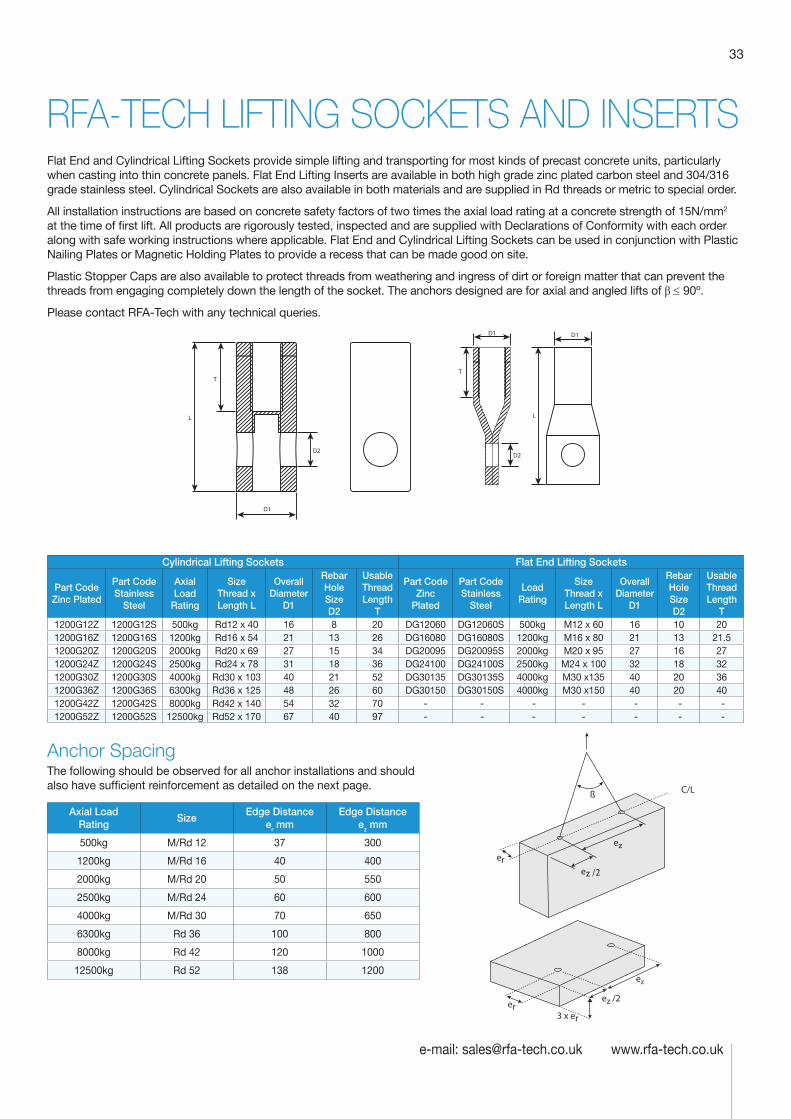
33
e-mail: [email protected] www.rfa-tech.co.uk
RFA-TECH LIFTING SOCKETS AND INSERTSFlat End and Cylindrical Lifting Sockets provide simple lifting and transporting for most kinds of precast concrete units, particularly when casting into thin concrete panels. Flat End Lifting Inserts are available in both high grade zinc plated carbon steel and 304/316 grade stainless steel. Cylindrical Sockets are also available in both materials and are supplied in Rd threads or metric to special order.
All installation instructions are based on concrete safety factors of two times the axial load rating at a concrete strength of 15N/mm2 at the time of first lift. All products are rigorously tested, inspected and are supplied with Declarations of Conformity with each order along with safe working instructions where applicable. Flat End and Cylindrical Lifting Sockets can be used in conjunction with Plastic Nailing Plates or Magnetic Holding Plates to provide a recess that can be made good on site.
Plastic Stopper Caps are also available to protect threads from weathering and ingress of dirt or foreign matter that can prevent the threads from engaging completely down the length of the socket. The anchors designed are for axial and angled lifts of β ≤ 90º.
Please contact RFA-Tech with any technical queries.
D1
L
T
D1
D2
T
L
D2
D1
Cylindrical Lifting Sockets Flat End Lifting Sockets
Part Code Zinc Plated
Part Code Stainless
Steel
Axial Load
Rating
Size Thread x Length L
Overall Diameter
D1
Rebar Hole Size D2
Usable Thread Length
T
Part Code Zinc
Plated
Part Code Stainless
Steel
Load Rating
Size Thread x Length L
Overall Diameter
D1
Rebar Hole Size D2
Usable Thread Length
T 1200G12Z 1200G12S 500kg Rd12 x 40 16 8 20 DG12060 DG12060S 500kg M12 x 60 16 10 201200G16Z 1200G16S 1200kg Rd16 x 54 21 13 26 DG16080 DG16080S 1200kg M16 x 80 21 13 21.5 1200G20Z 1200G20S 2000kg Rd20 x 69 27 15 34 DG20095 DG20095S 2000kg M20 x 95 27 16 271200G24Z 1200G24S 2500kg Rd24 x 78 31 18 36 DG24100 DG24100S 2500kg M24 x 100 32 18 321200G30Z 1200G30S 4000kg Rd30 x 103 40 21 52 DG30135 DG30135S 4000kg M30 x135 40 20 361200G36Z 1200G36S 6300kg Rd36 x 125 48 26 60 DG30150 DG30150S 4000kg M30 x150 40 20 40 1200G42Z 1200G42S 8000kg Rd42 x 140 54 32 70 - - - - - - - 1200G52Z 1200G52S 12500kg Rd52 x 170 67 40 97 - - - - - - -
Anchor SpacingThe following should be observed for all anchor installations and should also have sufficient reinforcement as detailed on the next page.
Axial Load Rating
Size Edge Distance
er mmEdge Distance
ez mm
500kg M/Rd 12 37 300
1200kg M/Rd 16 40 400
2000kg M/Rd 20 50 550
2500kg M/Rd 24 60 600
4000kg M/Rd 30 70 650
6300kg Rd 36 100 800
8000kg Rd 42 120 1000
12500kg Rd 52 138 1200
er
ez
ez /2
3 x er
er
ez
ez /2
ß C/L
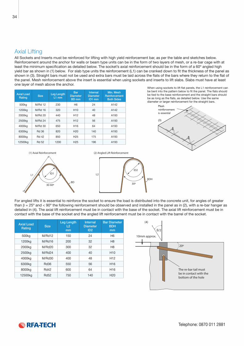
Technical Product Data
Reinforcement
All reinforcement bar used in the Startabox system is of grade B500C conforming to BS4449. Startabox is available containing 8mm to 20mm reinforcement with 12mm and 16mm being the most commonly used sizes. The rebar material is specially selected to be suitable for rebending, a prerequisite of the system, and is cut and bent to meet the requirements of BS8666, specific requirements of CARES Appendix TA2 and in line with the CARES Technical Approval on the Startabox system.
All reinforcement used is tested regularly, both in-house and independently, to ensure it continues to meet the requirements of BS4449 once rebent, offering confidence to detailers and engineers and supported by relevant and recent testing data.
Case
Startabox cases are manufactured from galvanised mild steel sheet rolled to precise dimensions. The cases are fully perforated on all faces to provide an excellent bond to the first concrete pour and provide an efficient key for the subsequent pour. The cases are annealed at specific points along the case to ease nailing when fixing to formwork. A wide range of case sizes are available to suit the rebar detail requirement.
Lid Cover
The Startabox system is fitted with a plastic tear off lid, to allow easy removal once required. The plastic lid has the advantages of no sharp edges, low weight, minimal concrete adherence and is suitable for recycling. Where necessary or requested, steel lid covers can be fitted.
End Cap Seal
Startabox cases are fitted with two easily removable plastic end cap seals. These ensure the concrete cannot enter the casing. End cap seals are suitable for recycling once removed.
Telephone: 0870 011 2881
6
Curved Startbox
34
Telephone: 0870 011 2881
Axial LiftingAll Sockets and Inserts must be reinforced for lifting with high yield reinforcement bar, as per the table and sketches below. Reinforcement around the anchor for walls or beam type units can be in the form of two layers of mesh, or a re-bar cage with at least the minimum specification as detailed below. The socket’s axial reinforcement should be in the form of a 60º angled high yield bar as shown in (1) below. For slab type units the reinforcement (L1) can be cranked down to fit the thickness of the panel as shown in (3). Straight bars must not be used and extra bars must be laid across the flats of the bars where they return to the flat of the panel. Mesh reinforcement above the insert is essential when using sockets and inserts to lift slabs. Slabs must have at least one layer of mesh above the anchor.
Axial Load Rating
Size Leg Length
L1 mm
Bar Diameter BD mm
Internal Diameter ID1 mm
Min. Mesh Reinforcement
Both Sides
500kg M/Rd 12 230 H6 24 A142
1200kg M/Rd 16 320 H10 40 A142
2000kg M/Rd 20 440 H12 48 A193
2500kg M/Rd 24 475 H12 56 A193
4000kg M/Rd 30 650 H16 64 A193
6300kg Rd 36 820 H20 140 A193
8000kg Rd 42 850 H25 175 A193
12500kg Rd 52 1200 H25 196 A193
(1) Axial Reinforcement
L2
30º
BDH
(2) Angled Lift Reinforcement
ID2
L1
30-60ºBD
ID1
For angled lifts it is essential to reinforce the socket to ensure the load is distributed into the concrete unit, for angles of greater than β = 25º and < 90º the following reinforcement should be observed and installed in the panel as in (2), with a re-bar hanger as detailed in (4). The axial lift reinforcement must be in contact with the base of the socket. The axial lift reinforcement must be in contact with the base of the socket and the angled lift reinforcement must be in contact with the barrel of the socket.
Axial Load Rating
Size Leg Length
L2 mm
Internal Diameter
ID2
Bar Diameter BDH mm
500kg M/Rd12 150 24 H6
1200kg M/Rd16 200 32 H8
2000kg M/Rd20 300 32 H8
2500kg M/Rd24 400 40 H10
4000kg M/Rd30 400 48 H12
6300kg Rd36 550 56 H16
8000kg Rd42 600 64 H16
12500kg Rd52 750 140 H20
When using sockets to lift flat panels, the L1 reinforcement can be bent into the pattern below to fit the panel. The flats should be tied to the base reinforcement and the straight bars should be as long as the flats, as detailed below. Use the same diameter or larger reinforcement for the straight bars.
(4)
The re-bar tail mustbe in contact with thebottom of the hole
10mm approx.
20º
ß/2
Mesh reinforcement is essential
(3)
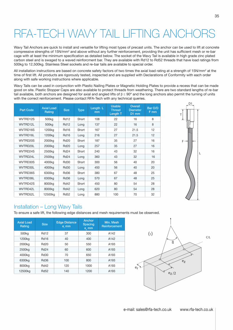
35
e-mail: [email protected] www.rfa-tech.co.uk
RFA-TECH WAVY TAIL LIFTING ANCHORSWavy Tail Anchors are quick to install and versatile for lifting most types of precast units. The anchor can be used to lift at concrete compressive strengths of 15N/mm2 and above without any further reinforcement, providing the unit has sufficient mesh or re-bar cage with at least the minimum specification as detailed below. The socket of the Wavy Tail is available in high grade zinc plated carbon steel and is swaged to a waved reinforcment bar. They are available with Rd12 to Rd52 threads that have load ratings from 500kg to 12,500kg. Stainless Steel sockets and re-bar tails are available to special order.
All installation instructions are based on concrete safety factors of two times the axial load rating at a strength of 15N/mm2 at the time of first lift. All products are rigorously tested, inspected and are supplied with Declarations of Conformity with each order along with safe working instructions where applicable.
Wavy Tails can be used in conjunction with Plastic Nailing Plates or Magnetic Holding Plates to provide a recess that can be made good on site. Plastic Stopper Caps are also available to protect threads from weathering. There are two standard lengths of re-bar tail available, both anchors are designed for axial and angled lifts of β ≤ 90º and the long anchors also permit the turning of units with the correct reinforcement. Please contact RFA-Tech with any technical queries.
Part CodeAxial Load
Rating Size Type
Length L mm
Usable Thread
Length T
Overall Diameter D1 mm
Bar O/D F mm
WVTRD12S 500kg Rd12 Short 108 22 16 8
WVTRD12L 500kg Rd12 Long 137 22 16 8
WVTRD16S 1200kg Rd16 Short 167 27 21.5 12
WVTRD16L 1200kg Rd16 Long 216 27 21.5 12
WVTRD20S 2000kg Rd20 Short 187 35 27 16
WVTRD20L 2000kg Rd20 Long 257 35 27 16
WVTRD24S 2500kg Rd24 Short 240 43 32 16
WVTRD24L 2500kg Rd24 Long 360 43 32 16
WVTRD30S 4000kg Rd30 Short 300 56 40 20
WVTRD30L 4000kg Rd30 Long 450 56 40 20
WVTRD36S 6300kg Rd36 Short 380 67 48 25
WVTRD36L 6300kg Rd36 Long 570 67 48 25
WVTRD42S 8000kg Rd42 Short 450 80 54 28
WVTRD42L 8000kg Rd42 Long 620 80 54 28
WVTRD52L 12500kg Rd52 Long 880 100 70 32
Installation – Long Wavy TailsTo ensure a safe lift, the following edge distances and mesh requirements must be observed.
Axial Load Rating
Size Edge Distance
er mm
Anchor Spacing ez mm
Min. Mesh Reinforcement
500kg Rd12 37 300 A142
1200kg Rd16 40 400 A142
2000kg Rd20 50 550 A193
2500kg Rd24 60 600 A193
4000kg Rd30 70 650 A193
6300kg Rd36 100 800 A193
8000kg Rd42 120 1000 A193
12500kg Rd52 140 1200 A193
L
T
D1
F
er
ez
ez /2
ß
(1)C/L
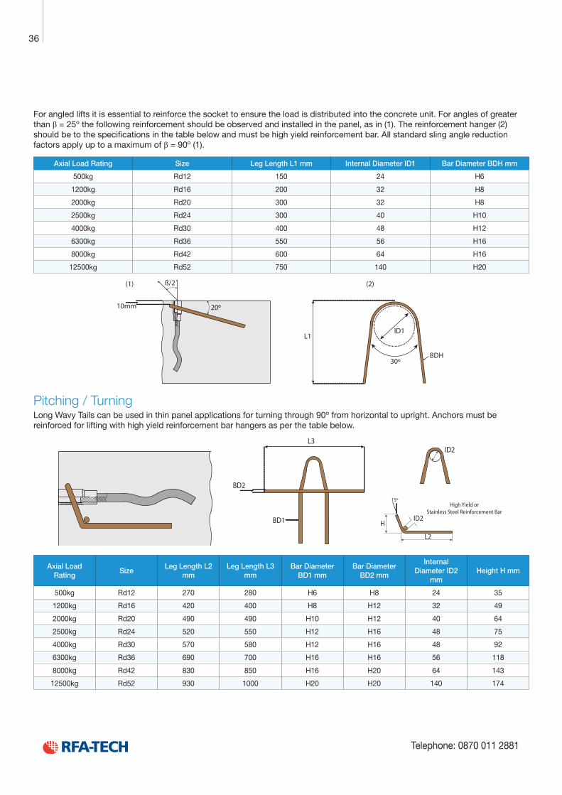
Technical Product Data
Reinforcement
All reinforcement bar used in the Startabox system is of grade B500C conforming to BS4449. Startabox is available containing 8mm to 20mm reinforcement with 12mm and 16mm being the most commonly used sizes. The rebar material is specially selected to be suitable for rebending, a prerequisite of the system, and is cut and bent to meet the requirements of BS8666, specific requirements of CARES Appendix TA2 and in line with the CARES Technical Approval on the Startabox system.
All reinforcement used is tested regularly, both in-house and independently, to ensure it continues to meet the requirements of BS4449 once rebent, offering confidence to detailers and engineers and supported by relevant and recent testing data.
Case
Startabox cases are manufactured from galvanised mild steel sheet rolled to precise dimensions. The cases are fully perforated on all faces to provide an excellent bond to the first concrete pour and provide an efficient key for the subsequent pour. The cases are annealed at specific points along the case to ease nailing when fixing to formwork. A wide range of case sizes are available to suit the rebar detail requirement.
Lid Cover
The Startabox system is fitted with a plastic tear off lid, to allow easy removal once required. The plastic lid has the advantages of no sharp edges, low weight, minimal concrete adherence and is suitable for recycling. Where necessary or requested, steel lid covers can be fitted.
End Cap Seal
Startabox cases are fitted with two easily removable plastic end cap seals. These ensure the concrete cannot enter the casing. End cap seals are suitable for recycling once removed.
Telephone: 0870 011 2881
6
Curved Startbox
36
Telephone: 0870 011 2881
For angled lifts it is essential to reinforce the socket to ensure the load is distributed into the concrete unit. For angles of greater than β = 25º the following reinforcement should be observed and installed in the panel, as in (1). The reinforcement hanger (2) should be to the specifications in the table below and must be high yield reinforcement bar. All standard sling angle reduction factors apply up to a maximum of β = 90º (1).
Axial Load Rating Size Leg Length L1 mm Internal Diameter ID1 Bar Diameter BDH mm
500kg Rd12 150 24 H6
1200kg Rd16 200 32 H8
2000kg Rd20 300 32 H8
2500kg Rd24 300 40 H10
4000kg Rd30 400 48 H12
6300kg Rd36 550 56 H16
8000kg Rd42 600 64 H16
12500kg Rd52 750 140 H20
L1
30º
(1) (2)
10mm
ß/2
20º
BDH
ID1
Pitching / TurningLong Wavy Tails can be used in thin panel applications for turning through 90º from horizontal to upright. Anchors must be reinforced for lifting with high yield reinforcement bar hangers as per the table below.
BD2
BD1
L3
High Yield orStainless Steel Reinforcement Bar
ID2
L2
H
ID2
15º
Axial Load Rating
Size Leg Length L2
mm Leg Length L3
mm Bar Diameter
BD1 mm Bar Diameter
BD2 mm
Internal Diameter ID2
mm Height H mm
500kg Rd12 270 280 H6 H8 24 35
1200kg Rd16 420 400 H8 H12 32 49
2000kg Rd20 490 490 H10 H12 40 64
2500kg Rd24 520 550 H12 H16 48 75
4000kg Rd30 570 580 H12 H16 48 92
6300kg Rd36 690 700 H16 H16 56 118
8000kg Rd42 830 850 H16 H20 64 143
12500kg Rd52 930 1000 H20 H20 140 174
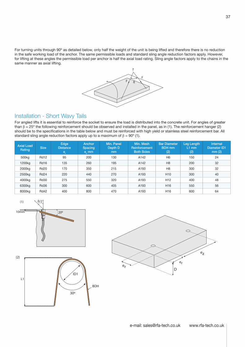
37
e-mail: [email protected] www.rfa-tech.co.uk
For turning units through 90º as detailed below, only half the weight of the unit is being lifted and therefore there is no reduction in the safe working load of the anchor. The same permissible loads and standard sling angle reduction factors apply. However, for lifting at these angles the permissible load per anchor is half the axial load rating. Sling angle factors apply to the chains in the same manner as axial lifting.
ßFF
Installation - Short Wavy TailsFor angled lifts it is essential to reinforce the socket to ensure the load is distributed into the concrete unit. For angles of greater than β = 25º the following reinforcement should be observed and installed in the panel, as in (1). The reinforcement hanger (2) should be to the specifications in the table below and must be reinforced with high yield or stainless steel reinforcement bar. All standard sling angle reduction factors apply up to a maximum of β = 90º (1).
Axial Load Rating
Size Edge
Distance er
Anchor Spacing ez mm
Min. Panel Depth D
mm
Min. Mesh Reinforcement
Both Sides
Bar Diameter BDH mm
(2)
Leg Length L1 mm
(2)
Internal Diameter ID1
mm (2)
500kg Rd12 95 200 130 A142 H6 150 24
1200kg Rd16 135 260 195 A142 H8 200 32
2000kg Rd20 170 350 215 A193 H8 300 32
2500kg Rd24 220 440 270 A193 H10 300 40
4000kg Rd30 275 550 320 A193 H12 400 48
6300kg Rd36 300 600 405 A193 H16 550 56
8000kg Rd42 400 800 470 A193 H16 600 64
L1
30º
BDH
ID1
(2)
er
ez
er
(1)
10mm
ß/2
20º
D
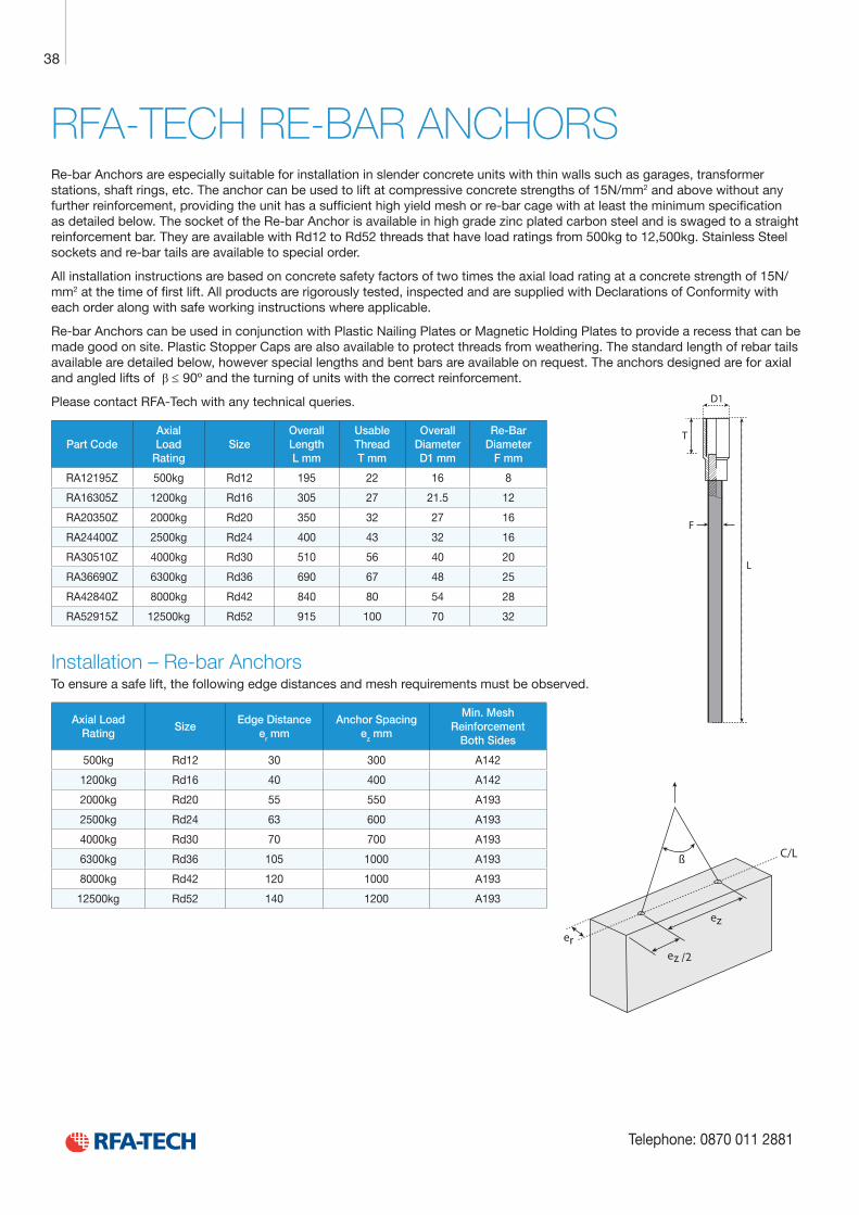
Technical Product Data
Reinforcement
All reinforcement bar used in the Startabox system is of grade B500C conforming to BS4449. Startabox is available containing 8mm to 20mm reinforcement with 12mm and 16mm being the most commonly used sizes. The rebar material is specially selected to be suitable for rebending, a prerequisite of the system, and is cut and bent to meet the requirements of BS8666, specific requirements of CARES Appendix TA2 and in line with the CARES Technical Approval on the Startabox system.
All reinforcement used is tested regularly, both in-house and independently, to ensure it continues to meet the requirements of BS4449 once rebent, offering confidence to detailers and engineers and supported by relevant and recent testing data.
Case
Startabox cases are manufactured from galvanised mild steel sheet rolled to precise dimensions. The cases are fully perforated on all faces to provide an excellent bond to the first concrete pour and provide an efficient key for the subsequent pour. The cases are annealed at specific points along the case to ease nailing when fixing to formwork. A wide range of case sizes are available to suit the rebar detail requirement.
Lid Cover
The Startabox system is fitted with a plastic tear off lid, to allow easy removal once required. The plastic lid has the advantages of no sharp edges, low weight, minimal concrete adherence and is suitable for recycling. Where necessary or requested, steel lid covers can be fitted.
End Cap Seal
Startabox cases are fitted with two easily removable plastic end cap seals. These ensure the concrete cannot enter the casing. End cap seals are suitable for recycling once removed.
Telephone: 0870 011 2881
6
Curved Startbox
38
Telephone: 0870 011 2881
RFA-TECH RE-BAR ANCHORSRe-bar Anchors are especially suitable for installation in slender concrete units with thin walls such as garages, transformer stations, shaft rings, etc. The anchor can be used to lift at compressive concrete strengths of 15N/mm2 and above without any further reinforcement, providing the unit has a sufficient high yield mesh or re-bar cage with at least the minimum specification as detailed below. The socket of the Re-bar Anchor is available in high grade zinc plated carbon steel and is swaged to a straight reinforcement bar. They are available with Rd12 to Rd52 threads that have load ratings from 500kg to 12,500kg. Stainless Steel sockets and re-bar tails are available to special order.
All installation instructions are based on concrete safety factors of two times the axial load rating at a concrete strength of 15N/mm2 at the time of first lift. All products are rigorously tested, inspected and are supplied with Declarations of Conformity with each order along with safe working instructions where applicable.
Re-bar Anchors can be used in conjunction with Plastic Nailing Plates or Magnetic Holding Plates to provide a recess that can be made good on site. Plastic Stopper Caps are also available to protect threads from weathering. The standard length of rebar tails available are detailed below, however special lengths and bent bars are available on request. The anchors designed are for axial and angled lifts of β ≤ 90º and the turning of units with the correct reinforcement.
Please contact RFA-Tech with any technical queries.
Part CodeAxial Load
Rating Size
Overall Length L mm
Usable Thread T mm
Overall Diameter D1 mm
Re-Bar Diameter
F mm
RA12195Z 500kg Rd12 195 22 16 8
RA16305Z 1200kg Rd16 305 27 21.5 12
RA20350Z 2000kg Rd20 350 32 27 16
RA24400Z 2500kg Rd24 400 43 32 16
RA30510Z 4000kg Rd30 510 56 40 20
RA36690Z 6300kg Rd36 690 67 48 25
RA42840Z 8000kg Rd42 840 80 54 28
RA52915Z 12500kg Rd52 915 100 70 32
Installation – Re-bar AnchorsTo ensure a safe lift, the following edge distances and mesh requirements must be observed.
Axial Load Rating
Size Edge Distance
er mmAnchor Spacing
ez mm
Min. Mesh Reinforcement
Both Sides
500kg Rd12 30 300 A142
1200kg Rd16 40 400 A142
2000kg Rd20 55 550 A193
2500kg Rd24 63 600 A193
4000kg Rd30 70 700 A193
6300kg Rd36 105 1000 A193
8000kg Rd42 120 1000 A193
12500kg Rd52 140 1200 A193
L
T
D1
F
er
ez
ez /2
ß C/L
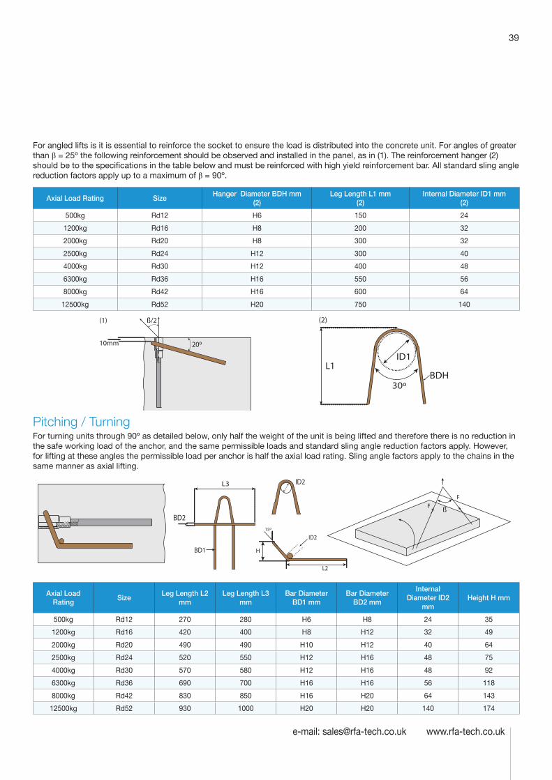
39
e-mail: [email protected] www.rfa-tech.co.uk
For angled lifts is it is essential to reinforce the socket to ensure the load is distributed into the concrete unit. For angles of greater than β = 25º the following reinforcement should be observed and installed in the panel, as in (1). The reinforcement hanger (2) should be to the specifications in the table below and must be reinforced with high yield reinforcement bar. All standard sling angle reduction factors apply up to a maximum of β = 90º.
Axial Load Rating Size Hanger Diameter BDH mm
(2)Leg Length L1 mm
(2)Internal Diameter ID1 mm
(2)
500kg Rd12 H6 150 24
1200kg Rd16 H8 200 32
2000kg Rd20 H8 300 32
2500kg Rd24 H12 300 40
4000kg Rd30 H12 400 48
6300kg Rd36 H16 550 56
8000kg Rd42 H16 600 64
12500kg Rd52 H20 750 140
L1
30ºBDH
ID1
(2)(1)
10mm
ß/2
20º
Pitching / TurningFor turning units through 90º as detailed below, only half the weight of the unit is being lifted and therefore there is no reduction in the safe working load of the anchor, and the same permissible loads and standard sling angle reduction factors apply. However, for lifting at these angles the permissible load per anchor is half the axial load rating. Sling angle factors apply to the chains in the same manner as axial lifting.
H
15º
ID2
ID2
BD2
BD1
L3
L2
ß
FF
Axial Load Rating
Size Leg Length L2
mm Leg Length L3
mm Bar Diameter
BD1 mm Bar Diameter
BD2 mm
Internal Diameter ID2
mm Height H mm
500kg Rd12 270 280 H6 H8 24 35
1200kg Rd16 420 400 H8 H12 32 49
2000kg Rd20 490 490 H10 H12 40 64
2500kg Rd24 520 550 H12 H16 48 75
4000kg Rd30 570 580 H12 H16 48 92
6300kg Rd36 690 700 H16 H16 56 118
8000kg Rd42 830 850 H16 H20 64 143
12500kg Rd52 930 1000 H20 H20 140 174
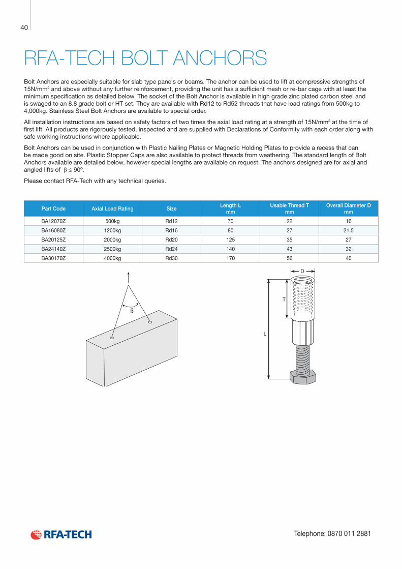
Technical Product Data
Reinforcement
All reinforcement bar used in the Startabox system is of grade B500C conforming to BS4449. Startabox is available containing 8mm to 20mm reinforcement with 12mm and 16mm being the most commonly used sizes. The rebar material is specially selected to be suitable for rebending, a prerequisite of the system, and is cut and bent to meet the requirements of BS8666, specific requirements of CARES Appendix TA2 and in line with the CARES Technical Approval on the Startabox system.
All reinforcement used is tested regularly, both in-house and independently, to ensure it continues to meet the requirements of BS4449 once rebent, offering confidence to detailers and engineers and supported by relevant and recent testing data.
Case
Startabox cases are manufactured from galvanised mild steel sheet rolled to precise dimensions. The cases are fully perforated on all faces to provide an excellent bond to the first concrete pour and provide an efficient key for the subsequent pour. The cases are annealed at specific points along the case to ease nailing when fixing to formwork. A wide range of case sizes are available to suit the rebar detail requirement.
Lid Cover
The Startabox system is fitted with a plastic tear off lid, to allow easy removal once required. The plastic lid has the advantages of no sharp edges, low weight, minimal concrete adherence and is suitable for recycling. Where necessary or requested, steel lid covers can be fitted.
End Cap Seal
Startabox cases are fitted with two easily removable plastic end cap seals. These ensure the concrete cannot enter the casing. End cap seals are suitable for recycling once removed.
Telephone: 0870 011 2881
6
Curved Startbox
40
Telephone: 0870 011 2881
RFA-TECH BOLT ANCHORSBolt Anchors are especially suitable for slab type panels or beams. The anchor can be used to lift at compressive strengths of 15N/mm2 and above without any further reinforcement, providing the unit has a sufficient mesh or re-bar cage with at least the minimum specification as detailed below. The socket of the Bolt Anchor is available in high grade zinc plated carbon steel and is swaged to an 8.8 grade bolt or HT set. They are available with Rd12 to Rd52 threads that have load ratings from 500kg to 4,000kg. Stainless Steel Bolt Anchors are available to special order.
All installation instructions are based on safety factors of two times the axial load rating at a strength of 15N/mm2 at the time of first lift. All products are rigorously tested, inspected and are supplied with Declarations of Conformity with each order along with safe working instructions where applicable.
Bolt Anchors can be used in conjunction with Plastic Nailing Plates or Magnetic Holding Plates to provide a recess that can be made good on site. Plastic Stopper Caps are also available to protect threads from weathering. The standard length of Bolt Anchors available are detailed below, however special lengths are available on request. The anchors designed are for axial and angled lifts of β ≤ 90º.
Please contact RFA-Tech with any technical queries.
Part Code Axial Load Rating Size Length L
mm Usable Thread T
mm Overall Diameter D
mm
BA12070Z 500kg Rd12 70 22 16
BA16080Z 1200kg Rd16 80 27 21.5
BA20125Z 2000kg Rd20 125 35 27
BA24140Z 2500kg Rd24 140 43 32
BA30170Z 4000kg Rd30 170 56 40
ß
D
T
L
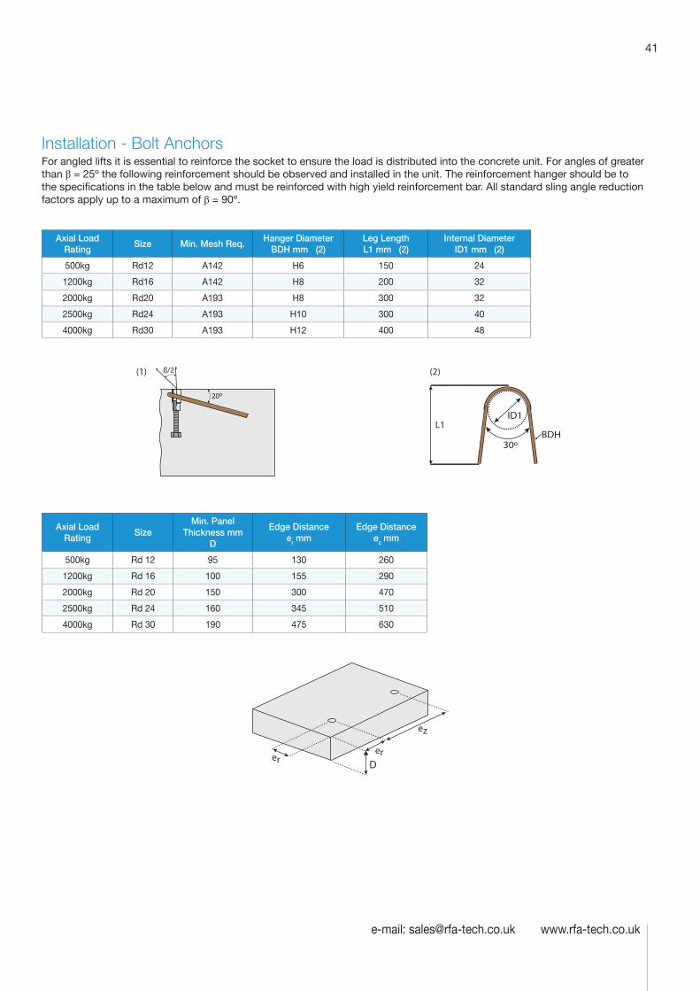
41
e-mail: [email protected] www.rfa-tech.co.uk
Installation - Bolt Anchors For angled lifts it is essential to reinforce the socket to ensure the load is distributed into the concrete unit. For angles of greater than β = 25º the following reinforcement should be observed and installed in the unit. The reinforcement hanger should be to the specifications in the table below and must be reinforced with high yield reinforcement bar. All standard sling angle reduction factors apply up to a maximum of β = 90º.
Axial Load Rating
Size Min. Mesh Req.Hanger Diameter
BDH mm (2)Leg Length L1 mm (2)
Internal Diameter ID1 mm (2)
500kg Rd12 A142 H6 150 24
1200kg Rd16 A142 H8 200 32
2000kg Rd20 A193 H8 300 32
2500kg Rd24 A193 H10 300 40
4000kg Rd30 A193 H12 400 48
L1
(2)
30ºBDH
ID1
(1) ß/2
20º
Axial Load Rating
Size Min. Panel
Thickness mm D
Edge Distance er mm
Edge Distance ez mm
500kg Rd 12 95 130 260
1200kg Rd 16 100 155 290
2000kg Rd 20 150 300 470
2500kg Rd 24 160 345 510
4000kg Rd 30 190 475 630
er
ez
er D
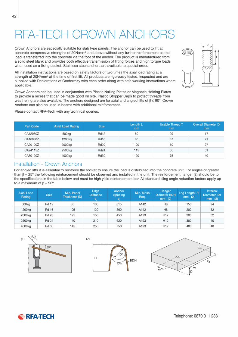
Technical Product Data
Reinforcement
All reinforcement bar used in the Startabox system is of grade B500C conforming to BS4449. Startabox is available containing 8mm to 20mm reinforcement with 12mm and 16mm being the most commonly used sizes. The rebar material is specially selected to be suitable for rebending, a prerequisite of the system, and is cut and bent to meet the requirements of BS8666, specific requirements of CARES Appendix TA2 and in line with the CARES Technical Approval on the Startabox system.
All reinforcement used is tested regularly, both in-house and independently, to ensure it continues to meet the requirements of BS4449 once rebent, offering confidence to detailers and engineers and supported by relevant and recent testing data.
Case
Startabox cases are manufactured from galvanised mild steel sheet rolled to precise dimensions. The cases are fully perforated on all faces to provide an excellent bond to the first concrete pour and provide an efficient key for the subsequent pour. The cases are annealed at specific points along the case to ease nailing when fixing to formwork. A wide range of case sizes are available to suit the rebar detail requirement.
Lid Cover
The Startabox system is fitted with a plastic tear off lid, to allow easy removal once required. The plastic lid has the advantages of no sharp edges, low weight, minimal concrete adherence and is suitable for recycling. Where necessary or requested, steel lid covers can be fitted.
End Cap Seal
Startabox cases are fitted with two easily removable plastic end cap seals. These ensure the concrete cannot enter the casing. End cap seals are suitable for recycling once removed.
Telephone: 0870 011 2881
6
Curved Startbox
42
Telephone: 0870 011 2881
RFA-TECH CROWN ANCHORSCrown Anchors are especially suitable for slab type panels. The anchor can be used to lift at concrete compressive strengths of 20N/mm2 and above without any further reinforcement as the load is transferred into the concrete via the foot of the anchor. The product is manufactured from a solid steel blank and provides both effective transmission of lifting forces and high torque loads when used as a fixing socket. Stainless steel anchors are available to special order.
All installation instructions are based on safety factors of two times the axial load rating at a strength of 20N/mm2 at the time of first lift. All products are rigorously tested, inspected and are supplied with Declarations of Conformity with each order along with safe working instructions where applicable.
Crown Anchors can be used in conjunction with Plastic Nailing Plates or Magnetic Holding Plates to provide a recess that can be made good on site. Plastic Stopper Caps to protect threads from weathering are also available. The anchors designed are for axial and angled lifts of β ≤ 90º. Crown Anchors can also be used in beams with additional reinforcement.
Please contact RFA-Tech with any technical queries.
L
T
D
Part Code Axial Load Rating Size Length L
mm Usable Thread T
mm Overall Diameter D
mm
CA12060Z 500kg Rd12 60 29 17
CA16080Z 1200kg Rd16 80 37 21
CA20100Z 2000kg Rd20 100 50 27
CA24115Z 2500kg Rd24 115 65 31
CA30120Z 4000kg Rd30 120 75 40
Installation - Crown AnchorsFor angled lifts it is essential to reinforce the socket to ensure the load is distributed into the concrete unit. For angles of greater than β = 25º the following reinforcement should be observed and installed in the unit. The reinforcement hanger (2) should be to the specifications in the table below and must be high yield reinforcement bar. All standard sling angle reduction factors apply up to a maximum of β = 90º.
Axial Load Rating
Size Min. Panel
Thickness (D)
Edge Distance
er
Anchor Spacing
ez
Min. Mesh Req.
Hanger Diameter BDH
mm (2)
Leg Length L1 mm (2)
Internal Diameter ID1
mm (2)
500kg Rd 12 85 105 315 A142 H8 150 24
1200kg Rd 16 105 120 360 A142 H8 200 32
2000kg Rd 20 125 150 450 A193 H12 300 32
2500kg Rd 24 140 210 620 A193 H12 300 40
4000kg Rd 30 145 250 750 A193 H12 400 48
L1
30º
(1)ß/2
20º
BDH
ID1
(2)
er
ez
erD
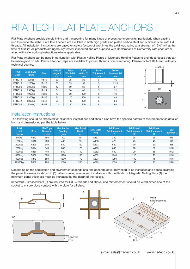
43
e-mail: [email protected] www.rfa-tech.co.uk
RFA-TECH FLAT PLATE ANCHORSFlat Plate Anchors provide simple lifting and transporting for many kinds of precast concrete units, particularly when casting into thin concrete slabs. Flat Plate Anchors are available in both high grade zinc plated carbon steel and stainless steel with Rd threads. All installation instructions are based on safety factors of two times the axial load rating at a strength of 15N/mm2 at the time of first lift. All products are rigorously tested, inspected and are supplied with Declarations of Conformity with each order along with safe working instructions where applicable.
Flat Plate Anchors can be used in conjunction with Plastic Nailing Plates or Magnetic Holding Plates to provide a recess that can be made good on site. Plastic Stopper Caps are available to protect threads from weathering. Please contact RFA-Tech with any technical queries.
Part Code
Axial Load Rating
Size Overall
Height L mm
Plate Width D1
mm
Plate Width D2
mm
Plate Thickness T
mm
Socket Diameter D3
mm
FPRD12 500kg Rd12 30 25 35 3 16
FPRD16 1200kg Rd16 35 35 50 3 21.5
FPRD20 2000kg Rd20 47 60 60 5 27
FPRD24 2500kg Rd24 54 60 80 5 32
FPRD30 4000kg Rd30 72 80 100 6 40
FPRD36 6300kg Rd36 84 100 130 6 48
FPRD42 8000kg Rd42 98 130 130 8 54
FPRD52 12500kg Rd52 117 130 150 8 68
Installation InstructionsThe following should be observed for all anchor installations and should also have the specific pattern of reinforcement as detailed in (1) and dimensioned per the table below.
Axial Load
Rating Size
Min.Edge Distance
er mm
Min. Anchor Spacing ez mm
Min. Panel Depth
et
Min. Mesh Req.
Additional Reinforcement
L1
Additional Reinforcement
L2
Additional Reinforcement
H
Bar Diameter D
500kg Rd12 150 300 75 A193 250 35 35 H6
1200kg Rd16 280 460 85 A193 420 45 45 H8
2000kg Rd20 340 680 100 A193 640 70 50 H8
2500kg Rd24 340 680 120 A193 640 90 60 H10
4000kg Rd30 440 880 140 A252 830 90 65 H12
6300kg Rd36 590 1180 160 A252 1140 110 75 H16
8000kg Rd42 650 1300 170 A393 1250 140 75 H16
12500kg Rd52 790 1580 200 A393 1530 140 95 H20
Depending on the application and environmental conditions, the concrete cover may need to be increased and hence enlarging the panel thickness as shown in (3). When making a recessed installation with the Plastic or Magnetic Nailing Plate (4) the minimum panel thickness must be increased by the depth of the recess.
Important – Crossed bars (2) are required for Rd 24 threads and above, and reinforcement should be wired either side of the socket to ensure close contact with the plate for all sizes.
(1)
L1
H
L2
(4)
(2)
30(3) Mesh
Reinforcement
ez
eret
er
ez
ConcreteCover
D
L
D3
T
D2
D1Rd
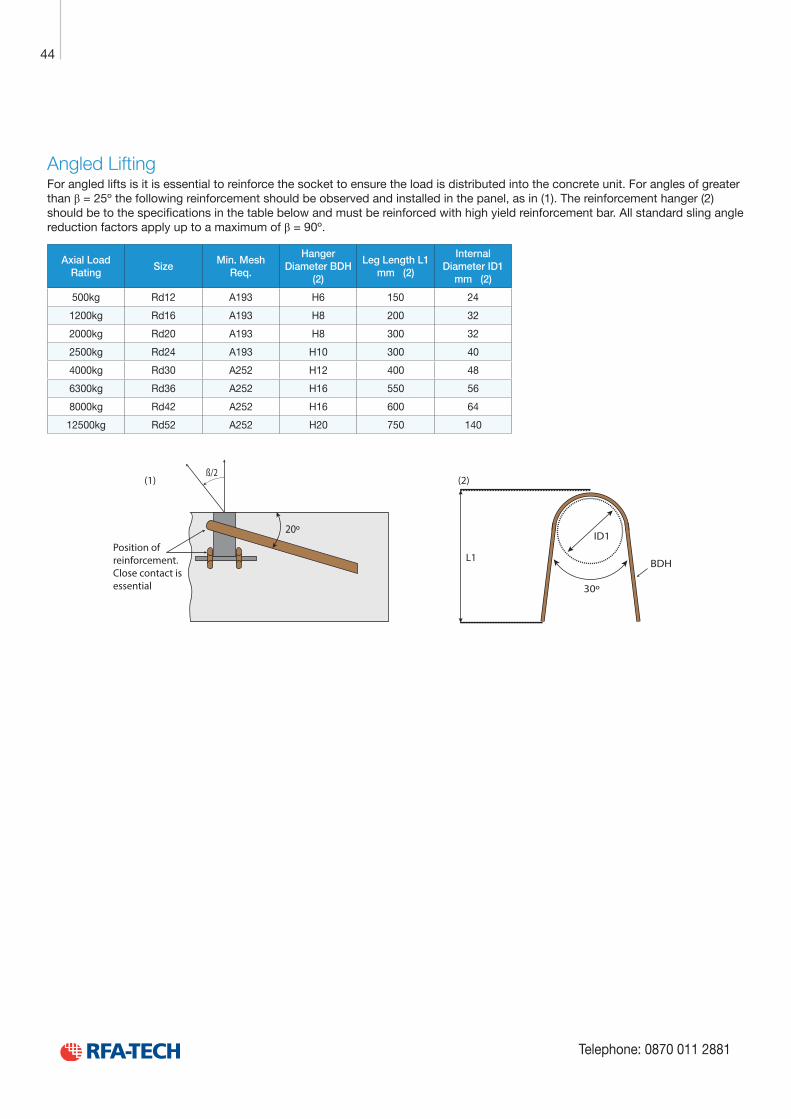
Technical Product Data
Reinforcement
All reinforcement bar used in the Startabox system is of grade B500C conforming to BS4449. Startabox is available containing 8mm to 20mm reinforcement with 12mm and 16mm being the most commonly used sizes. The rebar material is specially selected to be suitable for rebending, a prerequisite of the system, and is cut and bent to meet the requirements of BS8666, specific requirements of CARES Appendix TA2 and in line with the CARES Technical Approval on the Startabox system.
All reinforcement used is tested regularly, both in-house and independently, to ensure it continues to meet the requirements of BS4449 once rebent, offering confidence to detailers and engineers and supported by relevant and recent testing data.
Case
Startabox cases are manufactured from galvanised mild steel sheet rolled to precise dimensions. The cases are fully perforated on all faces to provide an excellent bond to the first concrete pour and provide an efficient key for the subsequent pour. The cases are annealed at specific points along the case to ease nailing when fixing to formwork. A wide range of case sizes are available to suit the rebar detail requirement.
Lid Cover
The Startabox system is fitted with a plastic tear off lid, to allow easy removal once required. The plastic lid has the advantages of no sharp edges, low weight, minimal concrete adherence and is suitable for recycling. Where necessary or requested, steel lid covers can be fitted.
End Cap Seal
Startabox cases are fitted with two easily removable plastic end cap seals. These ensure the concrete cannot enter the casing. End cap seals are suitable for recycling once removed.
Telephone: 0870 011 2881
6
Curved Startbox
44
Telephone: 0870 011 2881
Angled LiftingFor angled lifts is it is essential to reinforce the socket to ensure the load is distributed into the concrete unit. For angles of greater than β = 25º the following reinforcement should be observed and installed in the panel, as in (1). The reinforcement hanger (2) should be to the specifications in the table below and must be reinforced with high yield reinforcement bar. All standard sling angle reduction factors apply up to a maximum of β = 90º.
Axial Load Rating
Size Min. Mesh
Req.
Hanger Diameter BDH
(2)
Leg Length L1 mm (2)
Internal Diameter ID1
mm (2)
500kg Rd12 A193 H6 150 24
1200kg Rd16 A193 H8 200 32
2000kg Rd20 A193 H8 300 32
2500kg Rd24 A193 H10 300 40
4000kg Rd30 A252 H12 400 48
6300kg Rd36 A252 H16 550 56
8000kg Rd42 A252 H16 600 64
12500kg Rd52 A252 H20 750 140
L1
30º
(1)ß/2
20º
BDH
ID1
(2)
Position ofreinforcement.Close contact isessential
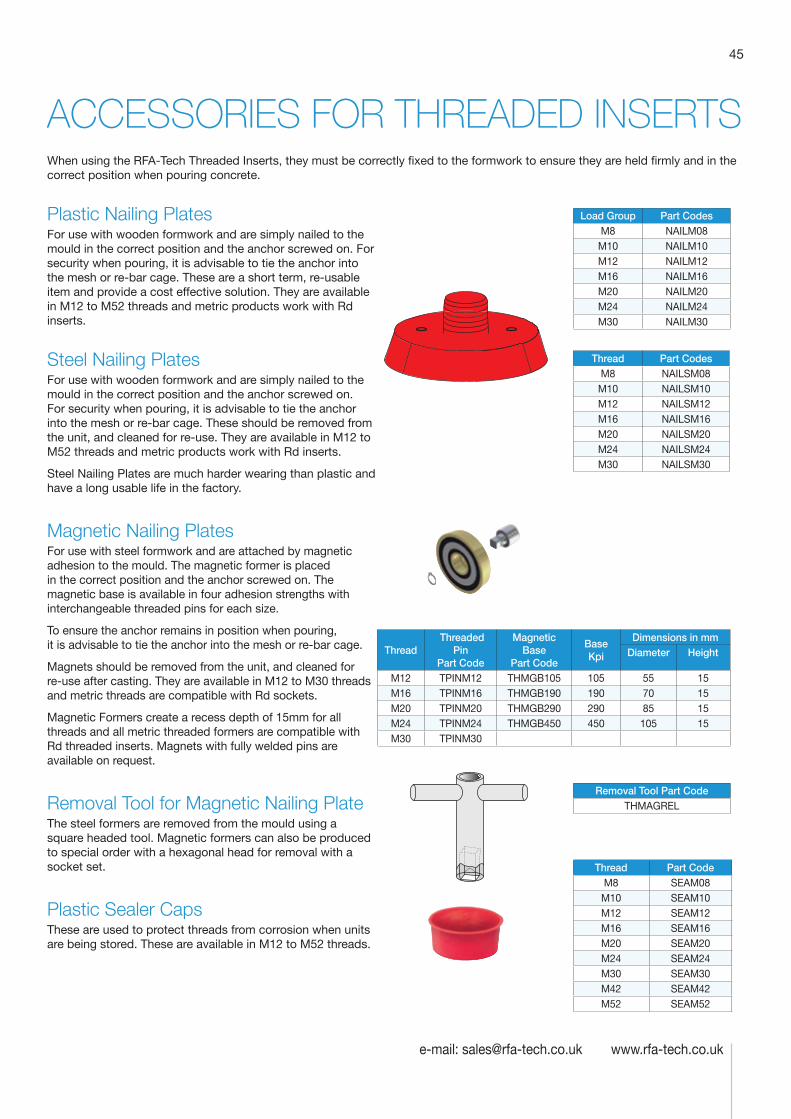
45
e-mail: [email protected] www.rfa-tech.co.uk
ACCESSORIES FOR THREADED INSERTSWhen using the RFA-Tech Threaded Inserts, they must be correctly fixed to the formwork to ensure they are held firmly and in the correct position when pouring concrete.
Plastic Nailing PlatesFor use with wooden formwork and are simply nailed to the mould in the correct position and the anchor screwed on. For security when pouring, it is advisable to tie the anchor into the mesh or re-bar cage. These are a short term, re-usable item and provide a cost effective solution. They are available in M12 to M52 threads and metric products work with Rd inserts.
Steel Nailing PlatesFor use with wooden formwork and are simply nailed to the mould in the correct position and the anchor screwed on. For security when pouring, it is advisable to tie the anchor into the mesh or re-bar cage. These should be removed from the unit, and cleaned for re-use. They are available in M12 to M52 threads and metric products work with Rd inserts.
Steel Nailing Plates are much harder wearing than plastic and have a long usable life in the factory.
Magnetic Nailing PlatesFor use with steel formwork and are attached by magnetic adhesion to the mould. The magnetic former is placed in the correct position and the anchor screwed on. The magnetic base is available in four adhesion strengths with interchangeable threaded pins for each size.
To ensure the anchor remains in position when pouring, it is advisable to tie the anchor into the mesh or re-bar cage.
Magnets should be removed from the unit, and cleaned for re-use after casting. They are available in M12 to M30 threads and metric threads are compatible with Rd sockets.
Magnetic Formers create a recess depth of 15mm for all threads and all metric threaded formers are compatible with Rd threaded inserts. Magnets with fully welded pins are available on request.
Removal Tool for Magnetic Nailing PlateThe steel formers are removed from the mould using a square headed tool. Magnetic formers can also be produced to special order with a hexagonal head for removal with a socket set.
Plastic Sealer CapsThese are used to protect threads from corrosion when units are being stored. These are available in M12 to M52 threads.
Load Group Part CodesM8 NAILM08M10 NAILM10M12 NAILM12M16 NAILM16M20 NAILM20M24 NAILM24M30 NAILM30
Thread Part CodesM8 NAILSM08M10 NAILSM10M12 NAILSM12M16 NAILSM16M20 NAILSM20M24 NAILSM24M30 NAILSM30
Thread Threaded
Pin Part Code
Magnetic Base
Part Code
Base Kpi
Dimensions in mmDiameter Height
M12 TPINM12 THMGB105 105 55 15M16 TPINM16 THMGB190 190 70 15M20 TPINM20 THMGB290 290 85 15M24 TPINM24 THMGB450 450 105 15M30 TPINM30
Removal Tool Part CodeTHMAGREL
Thread Part CodeM8 SEAM08M10 SEAM10M12 SEAM12M16 SEAM16M20 SEAM20M24 SEAM24M30 SEAM30M42 SEAM42M52 SEAM52
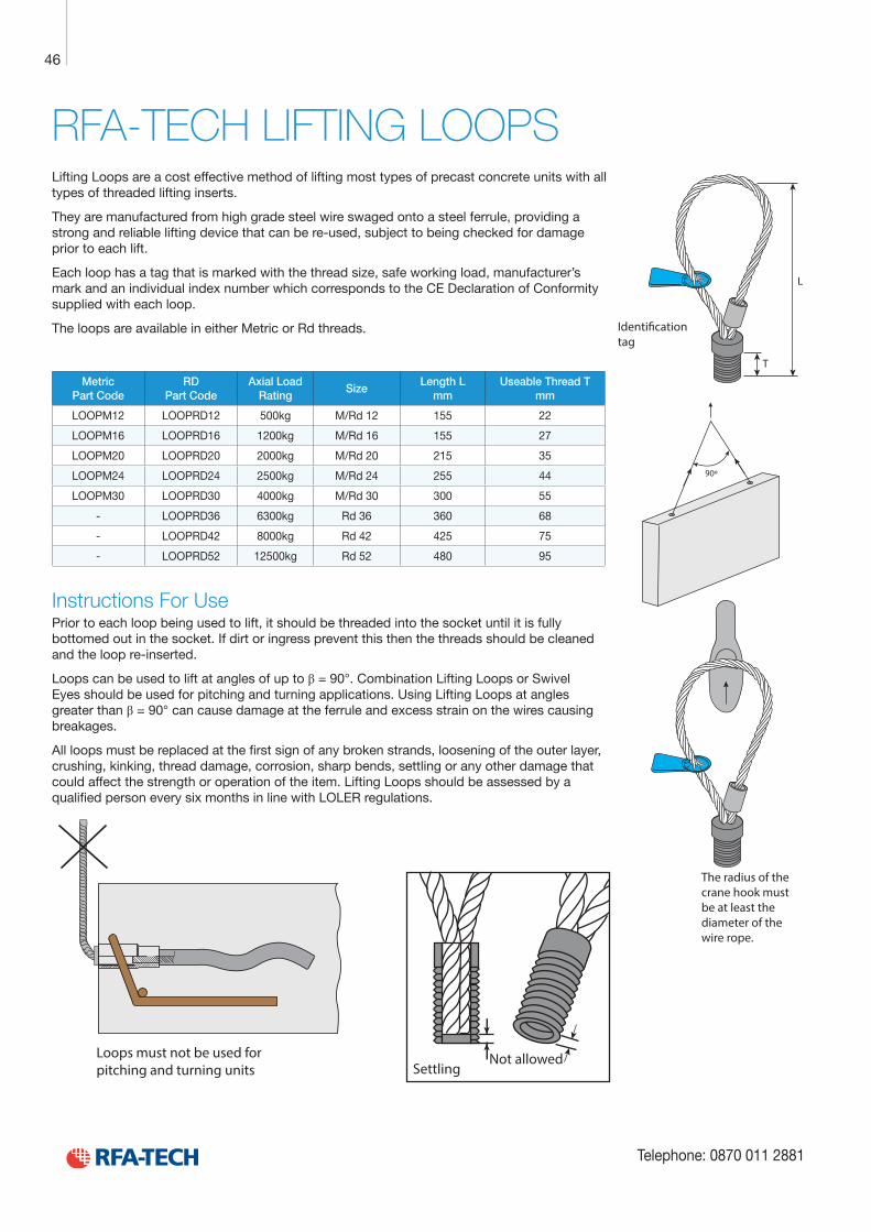
Technical Product Data
Reinforcement
All reinforcement bar used in the Startabox system is of grade B500C conforming to BS4449. Startabox is available containing 8mm to 20mm reinforcement with 12mm and 16mm being the most commonly used sizes. The rebar material is specially selected to be suitable for rebending, a prerequisite of the system, and is cut and bent to meet the requirements of BS8666, specific requirements of CARES Appendix TA2 and in line with the CARES Technical Approval on the Startabox system.
All reinforcement used is tested regularly, both in-house and independently, to ensure it continues to meet the requirements of BS4449 once rebent, offering confidence to detailers and engineers and supported by relevant and recent testing data.
Case
Startabox cases are manufactured from galvanised mild steel sheet rolled to precise dimensions. The cases are fully perforated on all faces to provide an excellent bond to the first concrete pour and provide an efficient key for the subsequent pour. The cases are annealed at specific points along the case to ease nailing when fixing to formwork. A wide range of case sizes are available to suit the rebar detail requirement.
Lid Cover
The Startabox system is fitted with a plastic tear off lid, to allow easy removal once required. The plastic lid has the advantages of no sharp edges, low weight, minimal concrete adherence and is suitable for recycling. Where necessary or requested, steel lid covers can be fitted.
End Cap Seal
Startabox cases are fitted with two easily removable plastic end cap seals. These ensure the concrete cannot enter the casing. End cap seals are suitable for recycling once removed.
Telephone: 0870 011 2881
6
Curved Startbox
46
Telephone: 0870 011 2881
RFA-TECH LIFTING LOOPSLifting Loops are a cost effective method of lifting most types of precast concrete units with all types of threaded lifting inserts.
They are manufactured from high grade steel wire swaged onto a steel ferrule, providing a strong and reliable lifting device that can be re-used, subject to being checked for damage prior to each lift.
Each loop has a tag that is marked with the thread size, safe working load, manufacturer’s mark and an individual index number which corresponds to the CE Declaration of Conformity supplied with each loop.
The loops are available in either Metric or Rd threads.
Metric Part Code
RD Part Code
Axial Load Rating
Size Length L
mm Useable Thread T
mm
LOOPM12 LOOPRD12 500kg M/Rd 12 155 22
LOOPM16 LOOPRD16 1200kg M/Rd 16 155 27
LOOPM20 LOOPRD20 2000kg M/Rd 20 215 35
LOOPM24 LOOPRD24 2500kg M/Rd 24 255 44
LOOPM30 LOOPRD30 4000kg M/Rd 30 300 55
- LOOPRD36 6300kg Rd 36 360 68
- LOOPRD42 8000kg Rd 42 425 75
- LOOPRD52 12500kg Rd 52 480 95
Instructions For UsePrior to each loop being used to lift, it should be threaded into the socket until it is fully bottomed out in the socket. If dirt or ingress prevent this then the threads should be cleaned and the loop re-inserted.
Loops can be used to lift at angles of up to β = 90°. Combination Lifting Loops or Swivel Eyes should be used for pitching and turning applications. Using Lifting Loops at angles greater than β = 90° can cause damage at the ferrule and excess strain on the wires causing breakages.
All loops must be replaced at the first sign of any broken strands, loosening of the outer layer, crushing, kinking, thread damage, corrosion, sharp bends, settling or any other damage that could affect the strength or operation of the item. Lifting Loops should be assessed by a qualified person every six months in line with LOLER regulations.
Loops must not be used forpitching and turning units
90º
The radius of thecrane hook mustbe at least the diameter of thewire rope.
L
T
Identi�cationtag
Not allowedSettling
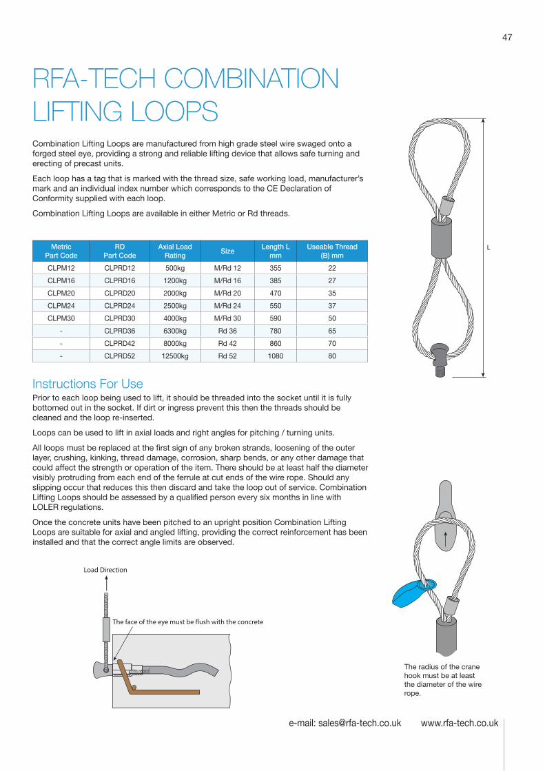
47
e-mail: [email protected] www.rfa-tech.co.uk
RFA-TECH COMBINATION LIFTING LOOPSCombination Lifting Loops are manufactured from high grade steel wire swaged onto a forged steel eye, providing a strong and reliable lifting device that allows safe turning and erecting of precast units.
Each loop has a tag that is marked with the thread size, safe working load, manufacturer’s mark and an individual index number which corresponds to the CE Declaration of Conformity supplied with each loop.
Combination Lifting Loops are available in either Metric or Rd threads.
Metric Part Code
RD Part Code
Axial Load Rating
Size Length L
mm Useable Thread
(B) mm
CLPM12 CLPRD12 500kg M/Rd 12 355 22
CLPM16 CLPRD16 1200kg M/Rd 16 385 27
CLPM20 CLPRD20 2000kg M/Rd 20 470 35
CLPM24 CLPRD24 2500kg M/Rd 24 550 37
CLPM30 CLPRD30 4000kg M/Rd 30 590 50
- CLPRD36 6300kg Rd 36 780 65
- CLPRD42 8000kg Rd 42 860 70
- CLPRD52 12500kg Rd 52 1080 80
Instructions For UsePrior to each loop being used to lift, it should be threaded into the socket until it is fully bottomed out in the socket. If dirt or ingress prevent this then the threads should be cleaned and the loop re-inserted.
Loops can be used to lift in axial loads and right angles for pitching / turning units.
All loops must be replaced at the first sign of any broken strands, loosening of the outer layer, crushing, kinking, thread damage, corrosion, sharp bends, or any other damage that could affect the strength or operation of the item. There should be at least half the diameter visibly protruding from each end of the ferrule at cut ends of the wire rope. Should any slipping occur that reduces this then discard and take the loop out of service. Combination Lifting Loops should be assessed by a qualified person every six months in line with LOLER regulations.
Once the concrete units have been pitched to an upright position Combination Lifting Loops are suitable for axial and angled lifting, providing the correct reinforcement has been installed and that the correct angle limits are observed.
Load Direction
The face of the eye must be �ush with the concrete
The radius of the crane hook must be at least the diameter of the wire rope.
L
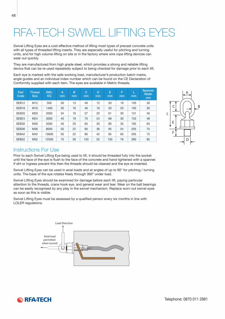
Technical Product Data
Reinforcement
All reinforcement bar used in the Startabox system is of grade B500C conforming to BS4449. Startabox is available containing 8mm to 20mm reinforcement with 12mm and 16mm being the most commonly used sizes. The rebar material is specially selected to be suitable for rebending, a prerequisite of the system, and is cut and bent to meet the requirements of BS8666, specific requirements of CARES Appendix TA2 and in line with the CARES Technical Approval on the Startabox system.
All reinforcement used is tested regularly, both in-house and independently, to ensure it continues to meet the requirements of BS4449 once rebent, offering confidence to detailers and engineers and supported by relevant and recent testing data.
Case
Startabox cases are manufactured from galvanised mild steel sheet rolled to precise dimensions. The cases are fully perforated on all faces to provide an excellent bond to the first concrete pour and provide an efficient key for the subsequent pour. The cases are annealed at specific points along the case to ease nailing when fixing to formwork. A wide range of case sizes are available to suit the rebar detail requirement.
Lid Cover
The Startabox system is fitted with a plastic tear off lid, to allow easy removal once required. The plastic lid has the advantages of no sharp edges, low weight, minimal concrete adherence and is suitable for recycling. Where necessary or requested, steel lid covers can be fitted.
End Cap Seal
Startabox cases are fitted with two easily removable plastic end cap seals. These ensure the concrete cannot enter the casing. End cap seals are suitable for recycling once removed.
Telephone: 0870 011 2881
6
Curved Startbox
48
Telephone: 0870 011 2881
RFA-TECH SWIVEL LIFTING EYESSwivel Lifting Eyes are a cost effective method of lifting most types of precast concrete units with all types of threaded lifting inserts. They are especially useful for pitching and turning units, and for high volume lifting on site or in the factory where wire rope lifting devices can wear out quickly.
They are manufactured from high grade steel, which provides a strong and reliable lifting device that can be re-used repeatedly subject to being checked for damage prior to each lift.
Each eye is marked with the safe working load, manufacturer’s production batch marks, angle guides and an individual index number which can be found on the CE Declaration of Conformity supplied with each item. The eyes are available in Metric threads.
Part Code
Thread Size
SWL KG
A mm
B mm
C mm
D mm
E mm
F mm
L mm
Spanner Width mm
SEB12 M12 500 30 13 46 12 50 18 105 30
SEB16 M16 1400 30 16 46 16 50 20 105 30
SEB20 M20 2000 34 16 57 20 61 30 131 40
SEB24 M24 3000 40 19 70 24 68 30 153 48
SEB30 M30 5000 40 20 65 30 80 35 165 65
SEB36 M36 8000 50 22 90 36 95 54 205 75
SEB42 M42 10000 50 22 90 42 95 63 205 75
SEB52 M52 12500 70 30 120 52 130 78 280 95
Instructions For UsePrior to each Swivel Lifting Eye being used to lift, it should be threaded fully into the socket until the face of the eye is flush to the face of the concrete and hand tightened with a spanner. If dirt or ingress prevent this then the threads should be cleaned and the eye re-inserted.
Swivel Lifting Eyes can be used in axial loads and at angles of up to 90° for pitching / turning units. The base of the eye rotates freely through 360° under load.
Swivel Lifting Eyes should be examined for damage before each lift, paying particular attention to the threads, crane hook eye, and general wear and tear. Wear on the ball bearings can be easily recognised by any play in the swivel mechanism. Replace worn out swivel eyes as soon as this is visible.
Swivel Lifting Eyes must be assessed by a qualified person every six months in line with LOLER regulations.
Load Direction
Axial loadpermitted
when turned
L
C B
E
F
D
A
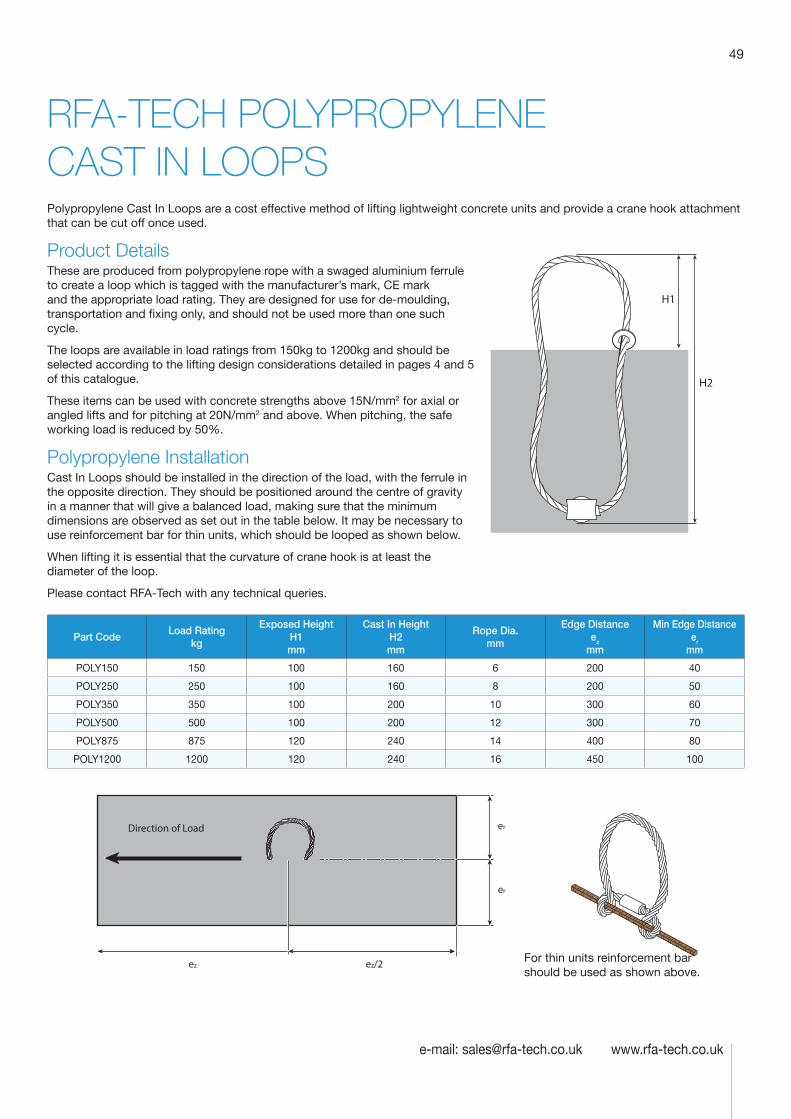
49
e-mail: [email protected] www.rfa-tech.co.uk
RFA-TECH POLYPROPYLENE CAST IN LOOPS Polypropylene Cast In Loops are a cost effective method of lifting lightweight concrete units and provide a crane hook attachment that can be cut off once used.
Product DetailsThese are produced from polypropylene rope with a swaged aluminium ferrule to create a loop which is tagged with the manufacturer’s mark, CE mark and the appropriate load rating. They are designed for use for de-moulding, transportation and fixing only, and should not be used more than one such cycle.
The loops are available in load ratings from 150kg to 1200kg and should be selected according to the lifting design considerations detailed in pages 4 and 5 of this catalogue.
These items can be used with concrete strengths above 15N/mm2 for axial or angled lifts and for pitching at 20N/mm2 and above. When pitching, the safe working load is reduced by 50%.
Polypropylene InstallationCast In Loops should be installed in the direction of the load, with the ferrule in the opposite direction. They should be positioned around the centre of gravity in a manner that will give a balanced load, making sure that the minimum dimensions are observed as set out in the table below. It may be necessary to use reinforcement bar for thin units, which should be looped as shown below.
When lifting it is essential that the curvature of crane hook is at least the diameter of the loop.
Please contact RFA-Tech with any technical queries.
H1
H2
Part CodeLoad Rating
kg
Exposed Height H1 mm
Cast In Height H2 mm
Rope Dia. mm
Edge Distance ez
mm
Min Edge Distance er
mm
POLY150 150 100 160 6 200 40
POLY250 250 100 160 8 200 50
POLY350 350 100 200 10 300 60
POLY500 500 100 200 12 300 70
POLY875 875 120 240 14 400 80
POLY1200 1200 120 240 16 450 100
ez ez/2
er
er
Direction of Load
For thin units reinforcement bar should be used as shown above.
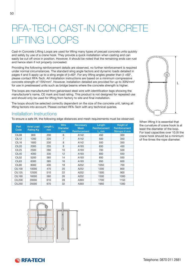
Technical Product Data
Reinforcement
All reinforcement bar used in the Startabox system is of grade B500C conforming to BS4449. Startabox is available containing 8mm to 20mm reinforcement with 12mm and 16mm being the most commonly used sizes. The rebar material is specially selected to be suitable for rebending, a prerequisite of the system, and is cut and bent to meet the requirements of BS8666, specific requirements of CARES Appendix TA2 and in line with the CARES Technical Approval on the Startabox system.
All reinforcement used is tested regularly, both in-house and independently, to ensure it continues to meet the requirements of BS4449 once rebent, offering confidence to detailers and engineers and supported by relevant and recent testing data.
Case
Startabox cases are manufactured from galvanised mild steel sheet rolled to precise dimensions. The cases are fully perforated on all faces to provide an excellent bond to the first concrete pour and provide an efficient key for the subsequent pour. The cases are annealed at specific points along the case to ease nailing when fixing to formwork. A wide range of case sizes are available to suit the rebar detail requirement.
Lid Cover
The Startabox system is fitted with a plastic tear off lid, to allow easy removal once required. The plastic lid has the advantages of no sharp edges, low weight, minimal concrete adherence and is suitable for recycling. Where necessary or requested, steel lid covers can be fitted.
End Cap Seal
Startabox cases are fitted with two easily removable plastic end cap seals. These ensure the concrete cannot enter the casing. End cap seals are suitable for recycling once removed.
Telephone: 0870 011 2881
6
Curved Startbox
50
Telephone: 0870 011 2881
RFA-TECH CAST-IN CONCRETE LIFTING LOOPSCast-In Concrete Lifting Loops are used for lifting many types of precast concrete units quickly and safely by use of a crane hook. They provide a quick installation when casting and can easily be cut off once in position. However, it should be noted that the remaining ends can rust and hence stain if not properly concealed.
Providing the following reinforcement details are observed, no further reinforcement is required under normal circumstances. The standard sling angle factors and dynamic loads detailed in pages 4 and 5 apply up to a sling angle of β=60º. For any lifting angles greater than β =60º, please contact RFA-Tech. All installation instructions are based on a minimum compressive concrete strength of 15N/mm2. However, installation detailed are provided for up to 30N/mm2 for use in prestressed units such as bridge beams where the concrete strength is higher.
The loops are manufactured from galvanised steel wire with identification tags showing the manufacturer’s name, CE mark and load rating. This product is not designed for repeated use and should only be used for lifting from factory to site and final installation.
The loops should be selected correctly dependent on the size of the concrete unit, taking all lifting factors into account. Please contact RFA-Tech with any technical queries.
Installation InstructionsTo ensure a safe lift, the following edge distances and mesh requirements must be observed.
Part Code
Axial Load Rating Kg
Length L mm
Wire Diameter
mm
Necessary Mesh
Reinforcement
Length Reinforcement
L2 mm
Height of Reinforcement Stirrups H mm
CIL08 800 200 6 A142 450 300 CIL12 1200 220 7 A142 500 350 CIL16 1600 230 8 A142 550 350 CIL20 2000 255 9 A193 650 450 CIL25 2500 280 10 A193 700 500 CIL40 4000 330 12 A193 800 550 CIL52 5200 385 14 A193 850 550 CIL63 6300 385 16 A193 950 600 CIL80 8000 430 18 A252 1050 700 CIL100 10000 470 20 A252 1200 800 CIL125 12500 510 22 A252 1300 900 CIL160 16000 560 26 A252 1500 1000 CIL200 20000 610 28 A393 1700 1150 CIL250 25000 670 32 A393 1950 1300
L
B540t
L2
H
When lifting it is essential that the curvature of crane hook is at least the diameter of the loop. For load capacities over 10.0t the crane hook should be a minimum of five times the rope diameter.
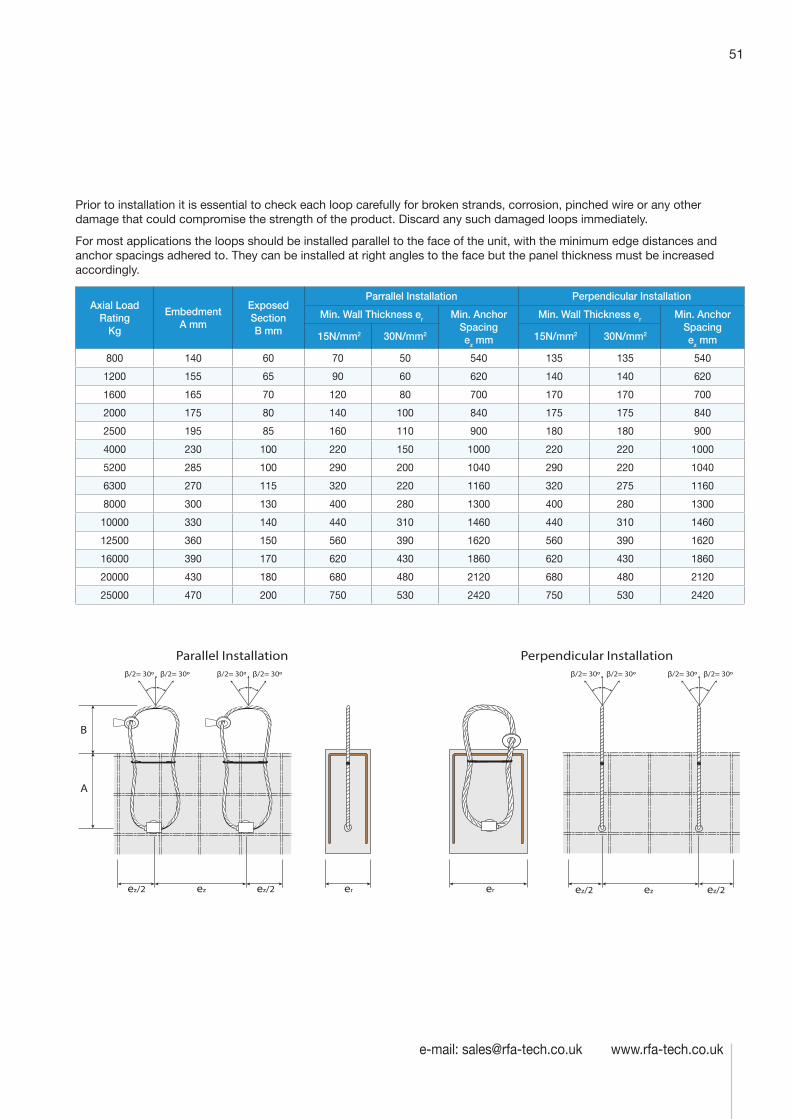
51
e-mail: [email protected] www.rfa-tech.co.uk
Prior to installation it is essential to check each loop carefully for broken strands, corrosion, pinched wire or any other damage that could compromise the strength of the product. Discard any such damaged loops immediately.
For most applications the loops should be installed parallel to the face of the unit, with the minimum edge distances and anchor spacings adhered to. They can be installed at right angles to the face but the panel thickness must be increased accordingly.
Axial Load Rating
Kg
Embedment A mm
Exposed Section B mm
Parrallel Installation Perpendicular Installation
Min. Wall Thickness er Min. Anchor Spacing ez mm
Min. Wall Thickness er Min. Anchor Spacing ez mm 15N/mm2 30N/mm2 15N/mm2 30N/mm2
800 140 60 70 50 540 135 135 540
1200 155 65 90 60 620 140 140 620
1600 165 70 120 80 700 170 170 700
2000 175 80 140 100 840 175 175 840
2500 195 85 160 110 900 180 180 900
4000 230 100 220 150 1000 220 220 1000
5200 285 100 290 200 1040 290 220 1040
6300 270 115 320 220 1160 320 275 1160
8000 300 130 400 280 1300 400 280 1300
10000 330 140 440 310 1460 440 310 1460
12500 360 150 560 390 1620 560 390 1620
16000 390 170 620 430 1860 620 430 1860
20000 430 180 680 480 2120 680 480 2120
25000 470 200 750 530 2420 750 530 2420
A
B
ez erez/2 ez/2 ez/2 ez/2ezer
β/2= 30º β/2= 30º β/2= 30º β/2= 30ºβ/2= 30º β/2= 30º β/2= 30º β/2= 30º
Parallel Installation Perpendicular Installation
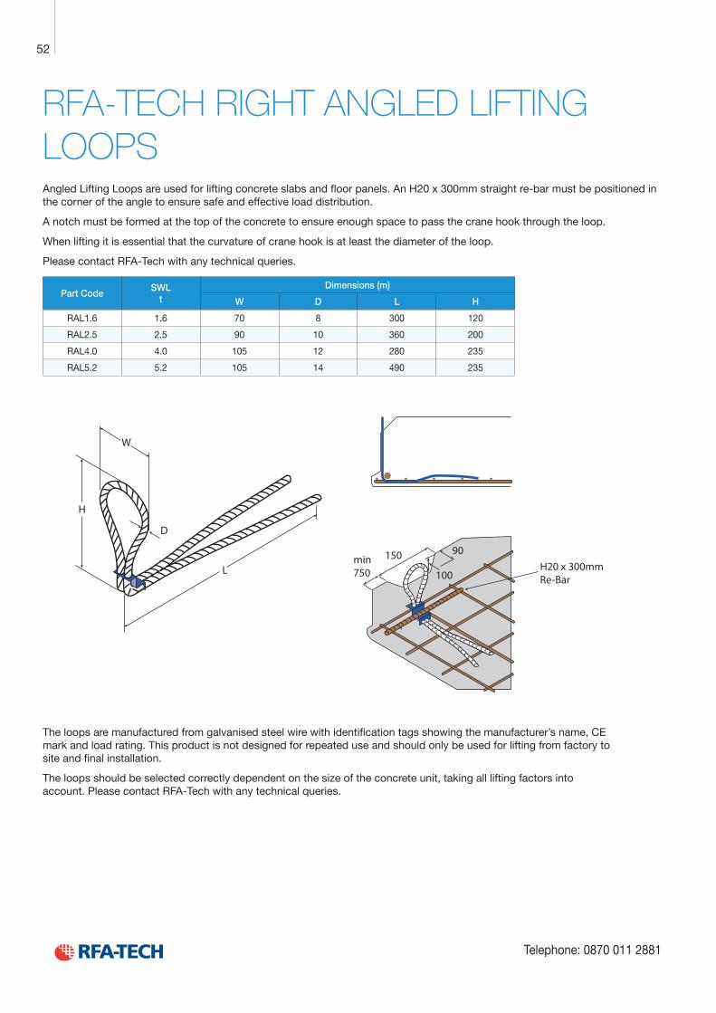
Technical Product Data
Reinforcement
All reinforcement bar used in the Startabox system is of grade B500C conforming to BS4449. Startabox is available containing 8mm to 20mm reinforcement with 12mm and 16mm being the most commonly used sizes. The rebar material is specially selected to be suitable for rebending, a prerequisite of the system, and is cut and bent to meet the requirements of BS8666, specific requirements of CARES Appendix TA2 and in line with the CARES Technical Approval on the Startabox system.
All reinforcement used is tested regularly, both in-house and independently, to ensure it continues to meet the requirements of BS4449 once rebent, offering confidence to detailers and engineers and supported by relevant and recent testing data.
Case
Startabox cases are manufactured from galvanised mild steel sheet rolled to precise dimensions. The cases are fully perforated on all faces to provide an excellent bond to the first concrete pour and provide an efficient key for the subsequent pour. The cases are annealed at specific points along the case to ease nailing when fixing to formwork. A wide range of case sizes are available to suit the rebar detail requirement.
Lid Cover
The Startabox system is fitted with a plastic tear off lid, to allow easy removal once required. The plastic lid has the advantages of no sharp edges, low weight, minimal concrete adherence and is suitable for recycling. Where necessary or requested, steel lid covers can be fitted.
End Cap Seal
Startabox cases are fitted with two easily removable plastic end cap seals. These ensure the concrete cannot enter the casing. End cap seals are suitable for recycling once removed.
Telephone: 0870 011 2881
6
Curved Startbox
52
Telephone: 0870 011 2881
RFA-TECH RIGHT ANGLED LIFTING LOOPSAngled Lifting Loops are used for lifting concrete slabs and floor panels. An H20 x 300mm straight re-bar must be positioned in the corner of the angle to ensure safe and effective load distribution.
A notch must be formed at the top of the concrete to ensure enough space to pass the crane hook through the loop.
When lifting it is essential that the curvature of crane hook is at least the diameter of the loop.
Please contact RFA-Tech with any technical queries.
Part CodeSWL
tDimensions (m)
W D L H
RAL1.6 1.6 70 8 300 120
RAL2.5 2.5 90 10 360 200
RAL4.0 4.0 105 12 280 235
RAL5.2 5.2 105 14 490 235
L
D
H
W
min750
150 90
100H20 x 300mm Re-Bar
The loops are manufactured from galvanised steel wire with identification tags showing the manufacturer’s name, CE mark and load rating. This product is not designed for repeated use and should only be used for lifting from factory to site and final installation.
The loops should be selected correctly dependent on the size of the concrete unit, taking all lifting factors into account. Please contact RFA-Tech with any technical queries.
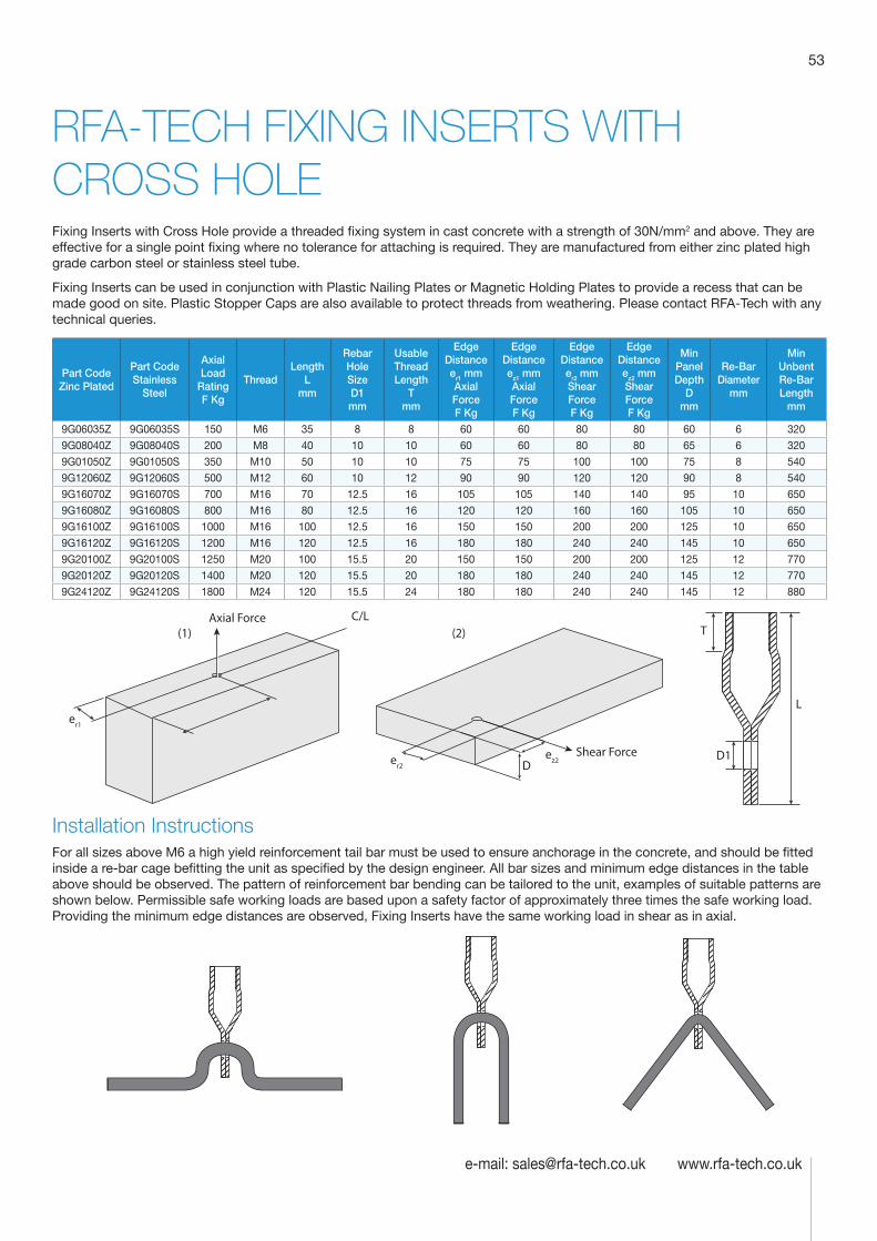
53
e-mail: [email protected] www.rfa-tech.co.uk
RFA-TECH FIXING INSERTS WITH CROSS HOLEFixing Inserts with Cross Hole provide a threaded fixing system in cast concrete with a strength of 30N/mm2 and above. They are effective for a single point fixing where no tolerance for attaching is required. They are manufactured from either zinc plated high grade carbon steel or stainless steel tube.
Fixing Inserts can be used in conjunction with Plastic Nailing Plates or Magnetic Holding Plates to provide a recess that can be made good on site. Plastic Stopper Caps are also available to protect threads from weathering. Please contact RFA-Tech with any technical queries.
Part Code Zinc Plated
Part Code Stainless
Steel
Axial Load
Rating F Kg
Thread Length
L mm
Rebar Hole Size D1 mm
Usable Thread Length
T mm
Edge Distance er1 mm Axial Force F Kg
Edge Distance ez1 mm Axial Force F Kg
Edge Distance er2 mm Shear Force F Kg
Edge Distance ez2 mm Shear Force F Kg
Min Panel Depth
D mm
Re-Bar Diameter
mm
Min Unbent Re-Bar Length
mm
9G06035Z 9G06035S 150 M6 35 8 8 60 60 80 80 60 6 320
9G08040Z 9G08040S 200 M8 40 10 10 60 60 80 80 65 6 320
9G01050Z 9G01050S 350 M10 50 10 10 75 75 100 100 75 8 540
9G12060Z 9G12060S 500 M12 60 10 12 90 90 120 120 90 8 540
9G16070Z 9G16070S 700 M16 70 12.5 16 105 105 140 140 95 10 650
9G16080Z 9G16080S 800 M16 80 12.5 16 120 120 160 160 105 10 650
9G16100Z 9G16100S 1000 M16 100 12.5 16 150 150 200 200 125 10 650
9G16120Z 9G16120S 1200 M16 120 12.5 16 180 180 240 240 145 10 650
9G20100Z 9G20100S 1250 M20 100 15.5 20 150 150 200 200 125 12 770
9G20120Z 9G20120S 1400 M20 120 15.5 20 180 180 240 240 145 12 770
9G24120Z 9G24120S 1800 M24 120 15.5 24 180 180 240 240 145 12 880
L
T
D1ez2er2
er1 ez1
(2)(1)C/LAxial Force
Shear ForceD
Installation InstructionsFor all sizes above M6 a high yield reinforcement tail bar must be used to ensure anchorage in the concrete, and should be fitted inside a re-bar cage befitting the unit as specified by the design engineer. All bar sizes and minimum edge distances in the table above should be observed. The pattern of reinforcement bar bending can be tailored to the unit, examples of suitable patterns are shown below. Permissible safe working loads are based upon a safety factor of approximately three times the safe working load. Providing the minimum edge distances are observed, Fixing Inserts have the same working load in shear as in axial.
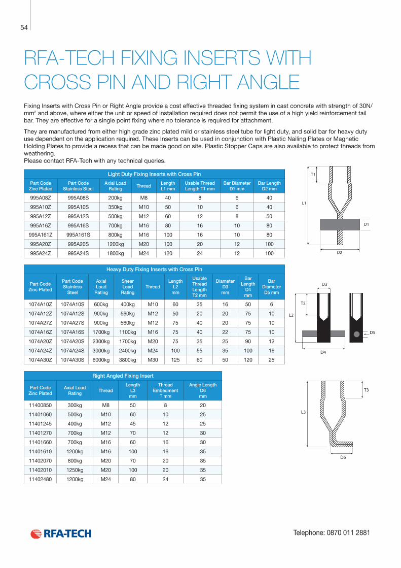
Technical Product Data
Reinforcement
All reinforcement bar used in the Startabox system is of grade B500C conforming to BS4449. Startabox is available containing 8mm to 20mm reinforcement with 12mm and 16mm being the most commonly used sizes. The rebar material is specially selected to be suitable for rebending, a prerequisite of the system, and is cut and bent to meet the requirements of BS8666, specific requirements of CARES Appendix TA2 and in line with the CARES Technical Approval on the Startabox system.
All reinforcement used is tested regularly, both in-house and independently, to ensure it continues to meet the requirements of BS4449 once rebent, offering confidence to detailers and engineers and supported by relevant and recent testing data.
Case
Startabox cases are manufactured from galvanised mild steel sheet rolled to precise dimensions. The cases are fully perforated on all faces to provide an excellent bond to the first concrete pour and provide an efficient key for the subsequent pour. The cases are annealed at specific points along the case to ease nailing when fixing to formwork. A wide range of case sizes are available to suit the rebar detail requirement.
Lid Cover
The Startabox system is fitted with a plastic tear off lid, to allow easy removal once required. The plastic lid has the advantages of no sharp edges, low weight, minimal concrete adherence and is suitable for recycling. Where necessary or requested, steel lid covers can be fitted.
End Cap Seal
Startabox cases are fitted with two easily removable plastic end cap seals. These ensure the concrete cannot enter the casing. End cap seals are suitable for recycling once removed.
Telephone: 0870 011 2881
6
Curved Startbox
54
Telephone: 0870 011 2881
RFA-TECH FIXING INSERTS WITH CROSS PIN AND RIGHT ANGLEFixing Inserts with Cross Pin or Right Angle provide a cost effective threaded fixing system in cast concrete with strength of 30N/mm2 and above, where either the unit or speed of installation required does not permit the use of a high yield reinforcement tail bar. They are effective for a single point fixing where no tolerance is required for attachment.
They are manufactured from either high grade zinc plated mild or stainless steel tube for light duty, and solid bar for heavy duty use dependent on the application required. These Inserts can be used in conjunction with Plastic Nailing Plates or Magnetic Holding Plates to provide a recess that can be made good on site. Plastic Stopper Caps are also available to protect threads from weathering. Please contact RFA-Tech with any technical queries.
Light Duty Fixing Inserts with Cross Pin
Part Code Zinc Plated
Part Code Stainless Steel
Axial Load Rating
Thread Length L1 mm
Usable Thread Length T1 mm
Bar Diameter D1 mm
Bar Length D2 mm
995A08Z 995A08S 200kg M8 40 8 6 40
995A10Z 995A10S 350kg M10 50 10 6 40
995A12Z 995A12S 500kg M12 60 12 8 50
995A16Z 995A16S 700kg M16 80 16 10 80
995A161Z 995A161S 800kg M16 100 16 10 80
995A20Z 995A20S 1200kg M20 100 20 12 100
995A24Z 995A24S 1800kg M24 120 24 12 100
Heavy Duty Fixing Inserts with Cross Pin
Part Code Zinc Plated
Part Code Stainless
Steel
Axial Load
Rating
Shear Load
Rating Thread
Length L2
mm
Usable Thread Length T2 mm
Diameter D3 mm
Bar Length
D4 mm
Bar Diameter D5 mm
1074A10Z 1074A10S 600kg 400kg M10 60 35 16 50 6
1074A12Z 1074A12S 900kg 560kg M12 50 20 20 75 10
1074A27Z 1074A27S 900kg 560kg M12 75 40 20 75 10
1074A16Z 1074A16S 1700kg 1100kg M16 75 40 22 75 10
1074A20Z 1074A20S 2300kg 1700kg M20 75 35 25 90 12
1074A24Z 1074A24S 3000kg 2400kg M24 100 55 35 100 16
1074A30Z 1074A30S 6000kg 3800kg M30 125 60 50 120 25
Right Angled Fixing Insert
Part Code Zinc Plated
Axial Load Rating
Thread Length
L3 mm
Thread Embedment
T mm
Angle Length D6 mm
11400850 300kg M8 50 8 20
11401060 500kg M10 60 10 25
11401245 400kg M12 45 12 25
11401270 700kg M12 70 12 30
11401660 700kg M16 60 16 30
11401610 1200kg M16 100 16 35
11402070 800kg M20 70 20 35
11402010 1250kg M20 100 20 35
11402480 1200kg M24 80 24 35
L1
D2
T1
D1
D4
L2
D5
T2
D3
T3
L3
D6
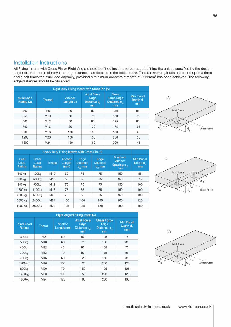
55
e-mail: [email protected] www.rfa-tech.co.uk
Installation InstructionsAll Fixing Inserts with Cross Pin or Right Angle should be fitted inside a re-bar cage befitting the unit as specified by the design engineer, and should observe the edge distances as detailed in the table below. The safe working loads are based upon a three and a half times the axial load capacity, provided a minimum concrete strength of 30N/mm2 has been achieved. The following edge distances should be observed.
Light Duty Fixing Insert with Cross Pin (A)
Axial Load Rating Kg
ThreadAnchor
Length L1
Axial Force Edge
Distance er1 mm
Shear Force Edge Distance er2
mm
Min. Panel Depth d1
mm
200 M8 40 60 125 65
350 M10 50 75 150 75
500 M12 60 90 125 85
700 M16 80 120 175 105
800 M16 100 150 150 125
1200 M20 100 150 250 125
1800 M24 120 180 200 145
Heavy Duty Fixing Inserts with Cross Pin (B)
Axial Load
Rating
Shear Load
RatingThread
Anchor Length (mm)
Edge Distance er2 mm
Edge Distance er2 mm
Minimum Anchor
Spacing ez2 mm
Min Panel Depth d2
mm
600kg 400kg M10 60 75 75 150 85
900kg 560kg M12 50 75 75 150 75
900kg 560kg M12 75 75 75 150 100
1700kg 1100kg M16 75 75 75 150 100
2300kg 1700kg M20 75 75 75 150 100
3000kg 2400kg M24 100 100 100 200 125
6000kg 3800kg M30 125 125 125 250 150
Right Angled Fixing Insert (C)
Axial Load Rating
Thread Anchor
Length mm
Axial Force Edge
Distance er3 mm
Shear Force Edge
Distance er3 mm
Min Panel Depth d3
mm
300kg M8 50 60 125 75
500kg M10 60 75 150 85
400kg M12 45 90 125 70
700kg M12 70 90 175 95
700kg M16 60 120 150 85
1200Kg M16 100 120 250 125
800kg M20 70 150 175 105
1250kg M20 100 150 250 125
1200kg M24 120 180 200 105
er1
er1d1
(A)
Axial Force
Shear Force
er2
er2
(B)
ez2
d2
Axial Force
Shear Force
er3
er3
(C)
d3
Axial Force
Shear Force
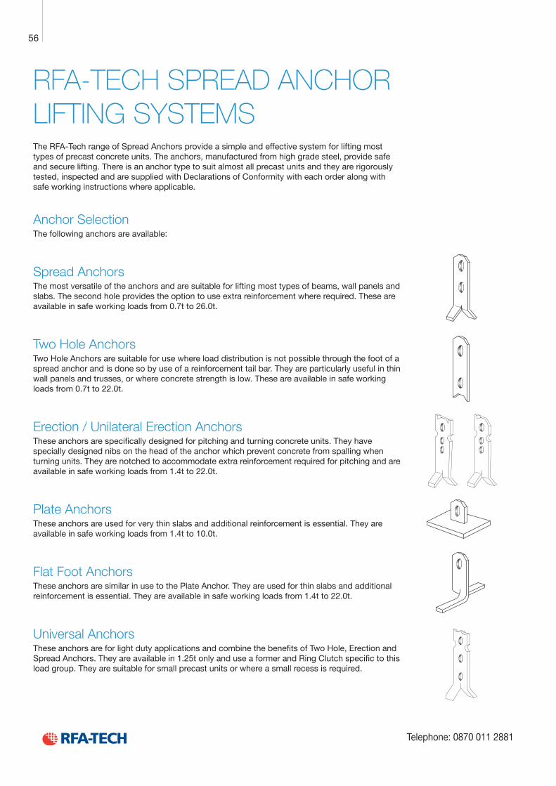
Technical Product Data
Reinforcement
All reinforcement bar used in the Startabox system is of grade B500C conforming to BS4449. Startabox is available containing 8mm to 20mm reinforcement with 12mm and 16mm being the most commonly used sizes. The rebar material is specially selected to be suitable for rebending, a prerequisite of the system, and is cut and bent to meet the requirements of BS8666, specific requirements of CARES Appendix TA2 and in line with the CARES Technical Approval on the Startabox system.
All reinforcement used is tested regularly, both in-house and independently, to ensure it continues to meet the requirements of BS4449 once rebent, offering confidence to detailers and engineers and supported by relevant and recent testing data.
Case
Startabox cases are manufactured from galvanised mild steel sheet rolled to precise dimensions. The cases are fully perforated on all faces to provide an excellent bond to the first concrete pour and provide an efficient key for the subsequent pour. The cases are annealed at specific points along the case to ease nailing when fixing to formwork. A wide range of case sizes are available to suit the rebar detail requirement.
Lid Cover
The Startabox system is fitted with a plastic tear off lid, to allow easy removal once required. The plastic lid has the advantages of no sharp edges, low weight, minimal concrete adherence and is suitable for recycling. Where necessary or requested, steel lid covers can be fitted.
End Cap Seal
Startabox cases are fitted with two easily removable plastic end cap seals. These ensure the concrete cannot enter the casing. End cap seals are suitable for recycling once removed.
Telephone: 0870 011 2881
6
Curved Startbox
56
Telephone: 0870 011 2881
RFA-TECH SPREAD ANCHOR LIFTING SYSTEMSThe RFA-Tech range of Spread Anchors provide a simple and effective system for lifting most types of precast concrete units. The anchors, manufactured from high grade steel, provide safe and secure lifting. There is an anchor type to suit almost all precast units and they are rigorously tested, inspected and are supplied with Declarations of Conformity with each order along with safe working instructions where applicable.
Anchor SelectionThe following anchors are available:
Spread AnchorsThe most versatile of the anchors and are suitable for lifting most types of beams, wall panels and slabs. The second hole provides the option to use extra reinforcement where required. These are available in safe working loads from 0.7t to 26.0t.
Two Hole AnchorsTwo Hole Anchors are suitable for use where load distribution is not possible through the foot of a spread anchor and is done so by use of a reinforcement tail bar. They are particularly useful in thin wall panels and trusses, or where concrete strength is low. These are available in safe working loads from 0.7t to 22.0t.
Erection / Unilateral Erection AnchorsThese anchors are specifically designed for pitching and turning concrete units. They have specially designed nibs on the head of the anchor which prevent concrete from spalling when turning units. They are notched to accommodate extra reinforcement required for pitching and are available in safe working loads from 1.4t to 22.0t.
Plate AnchorsThese anchors are used for very thin slabs and additional reinforcement is essential. They are available in safe working loads from 1.4t to 10.0t.
Flat Foot AnchorsThese anchors are similar in use to the Plate Anchor. They are used for thin slabs and additional reinforcement is essential. They are available in safe working loads from 1.4t to 22.0t.
Universal AnchorsThese anchors are for light duty applications and combine the benefits of Two Hole, Erection and Spread Anchors. They are available in 1.25t only and use a former and Ring Clutch specific to this load group. They are suitable for small precast units or where a small recess is required.
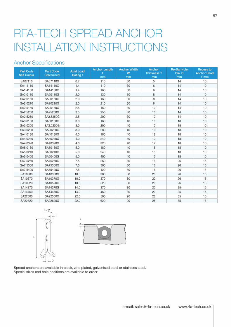
57
e-mail: [email protected] www.rfa-tech.co.uk
RFA-TECH SPREAD ANCHOR INSTALLATION INSTRUCTIONSAnchor Specifications
Part Code Self Colour
Part Code Galvanised
Axial Load Rating t
Anchor Length L
mm
Anchor Width W
mm
Anchor Thickness T
mm
Re-Bar Hole Dia. D mm
Recess to Anchor Head
F mmSA07110 SA07110G 0.7 110 30 5 14 10SA1.4110 SA14110G 1.4 110 30 6 14 10SA1.4160 SA14160G 1.4 160 30 6 14 10SA2.0130 SA20130G 2.0 130 30 8 14 10SA2.0160 SA20160G 2.0 160 30 8 14 10SA2.0210 SA20210G 2.0 210 30 8 14 10SA2.5150 SA25150G 2.5 150 30 10 14 10SA2.5200 SA25200G 2.5 250 30 10 14 10SA2.5250 SA2.5250G 2.5 200 30 10 14 10SA3.0160 SA30160G 3.0 160 40 10 18 10SA3.0200 SA3.0200G 3.0 200 40 10 18 10SA3.0280 SA30280G 3.0 280 40 10 18 10SA4.0180 SA40180G 4.0 180 40 12 18 10SA4.0240 SA40240G 4.0 240 40 12 18 10SA4.0320 SA40320G 4.0 320 40 12 18 10SA5.0180 SA50180G 5.0 180 40 15 18 10SA5.0240 SA50240G 5.0 240 40 15 18 10SA5.0400 SA50400G 5.0 400 40 15 18 10SA7.5260 SA75260G 7.5 260 60 16 26 15SA7.5300 SA75300G 7.5 300 60 16 26 15SA7.5420 SA75420G 7.5 420 60 16 26 15SA10300 SA10300G 10.0 300 60 20 26 15SA10370 SA10370G 10.0 370 60 20 26 15SA10520 SA10520G 10.0 520 60 20 26 15SA14370 SA14370G 14.0 370 80 20 35 15SA14460 SA14460G 14.0 460 80 20 35 15SA22500 SA22500G 22.0 500 90 28 35 15SA22620 SA22620G 22.0 620 90 28 35 15
D
T
W
L
F
Spread anchors are available in black, zinc plated, galvanised steel or stainless steel. Special sizes and hole positions are available to order.
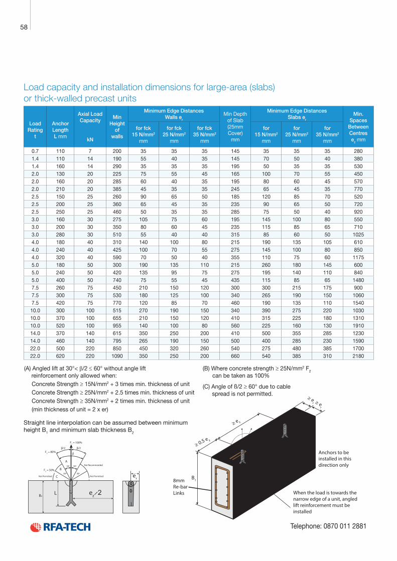
Technical Product Data
Reinforcement
All reinforcement bar used in the Startabox system is of grade B500C conforming to BS4449. Startabox is available containing 8mm to 20mm reinforcement with 12mm and 16mm being the most commonly used sizes. The rebar material is specially selected to be suitable for rebending, a prerequisite of the system, and is cut and bent to meet the requirements of BS8666, specific requirements of CARES Appendix TA2 and in line with the CARES Technical Approval on the Startabox system.
All reinforcement used is tested regularly, both in-house and independently, to ensure it continues to meet the requirements of BS4449 once rebent, offering confidence to detailers and engineers and supported by relevant and recent testing data.
Case
Startabox cases are manufactured from galvanised mild steel sheet rolled to precise dimensions. The cases are fully perforated on all faces to provide an excellent bond to the first concrete pour and provide an efficient key for the subsequent pour. The cases are annealed at specific points along the case to ease nailing when fixing to formwork. A wide range of case sizes are available to suit the rebar detail requirement.
Lid Cover
The Startabox system is fitted with a plastic tear off lid, to allow easy removal once required. The plastic lid has the advantages of no sharp edges, low weight, minimal concrete adherence and is suitable for recycling. Where necessary or requested, steel lid covers can be fitted.
End Cap Seal
Startabox cases are fitted with two easily removable plastic end cap seals. These ensure the concrete cannot enter the casing. End cap seals are suitable for recycling once removed.
Telephone: 0870 011 2881
6
Curved Startbox
58
Telephone: 0870 011 2881
Load capacity and installation dimensions for large-area (slabs) or thick-walled precast units
Load Rating
t
Anchor Length L mm
Axial Load Capacity
kN
Min Height
of walls
Minimum Edge Distances Walls er
Min Depth of Slab (25mm Cover)
mm
Minimum Edge Distances Slabs er
Min. Spaces
Between Centres ez mm
for fck 15 N/mm2
mm
for fck 25 N/mm2
mm
for fck 35 N/mm2
mm
for 15 N/mm2
mm
for 25 N/mm2
mm
for 35 N/mm2
mm
0.7 110 7 200 35 35 35 145 35 35 35 2801.4 110 14 190 55 40 35 145 70 50 40 3801.4 160 14 290 35 35 35 195 50 35 35 5302.0 130 20 225 75 55 45 165 100 70 55 4502.0 160 20 285 60 40 35 195 80 60 45 5702.0 210 20 385 45 35 35 245 65 45 35 7702.5 150 25 260 90 65 50 185 120 85 70 5202.5 200 25 360 65 45 35 235 90 65 50 7202.5 250 25 460 50 35 35 285 75 50 40 9203.0 160 30 275 105 75 60 195 145 100 80 5503.0 200 30 350 80 60 45 235 115 85 65 7103.0 280 30 510 55 40 40 315 85 60 50 10254.0 180 40 310 140 100 80 215 190 135 105 6104.0 240 40 425 100 70 55 275 145 100 80 8504.0 320 40 590 70 50 40 355 110 75 60 11755.0 180 50 300 190 135 110 215 260 180 145 6005.0 240 50 420 135 95 75 275 195 140 110 8405.0 400 50 740 75 55 45 435 115 85 65 14807.5 260 75 450 210 150 120 300 300 215 175 9007.5 300 75 530 180 125 100 340 265 190 150 10607.5 420 75 770 120 85 70 460 190 135 110 1540
10.0 300 100 515 270 190 150 340 390 275 220 103010.0 370 100 655 210 150 120 410 315 225 180 131010.0 520 100 955 140 100 80 560 225 160 130 191014.0 370 140 615 350 250 200 410 500 355 285 123014.0 460 140 795 265 190 150 500 400 285 230 159022.0 500 220 850 450 320 260 540 275 480 385 170022.0 620 220 1090 350 250 200 660 540 385 310 2180
8mm Re-barLinks
Anchors to be installed in this direction only
When the load is towards the narrow edge of a unit, angled lift reinforcement must be installed
er
LB2 ez ̷ 2
B1
30º
30º
30º
30º
F1 = 100%
F2 = 80%
F3 = 50%
β/2
β
β/2
C
B
A
Not Permitted Not Permitted
Not Recommended
(A) Angled lift at 30°< β/2 ≤ 60° without angle lift reinforcement only allowed when:
Concrete Strength ≥ 15N/mm2 + 3 times min. thickness of unitConcrete Strength ≥ 25N/mm2 + 2.5 times min. thickness of unitConcrete Strength ≥ 35N/mm2 + 2 times min. thickness of unit(min thickness of unit = 2 x er)
(B) Where concrete strength ≥ 25N/mm2 F2 can be taken as 100%
(C) Angle of ß/2 ≥ 60° due to cable spread is not permitted.
Straight line interpolation can be assumed between minimum height B1 and minimum slab thickness B2
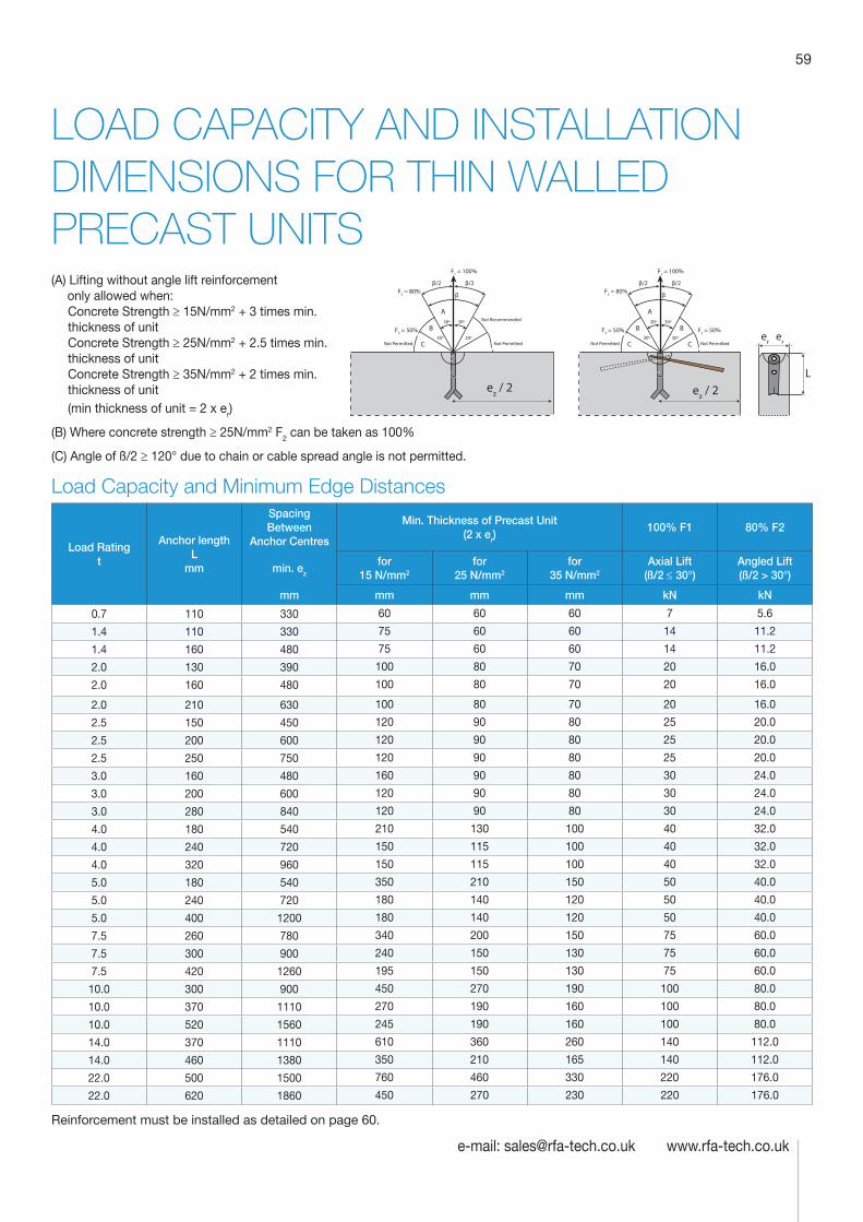
59
e-mail: [email protected] www.rfa-tech.co.uk
LOAD CAPACITY AND INSTALLATION DIMENSIONS FOR THIN WALLED PRECAST UNITS(A) Lifting without angle lift reinforcement only allowed when:
Concrete Strength ≥ 15N/mm2 + 3 times min. thickness of unitConcrete Strength ≥ 25N/mm2 + 2.5 times min. thickness of unitConcrete Strength ≥ 35N/mm2 + 2 times min. thickness of unit(min thickness of unit = 2 x er)
(B) Where concrete strength ≥ 25N/mm2 F2 can be taken as 100%
(C) Angle of ß/2 ≥ 120° due to chain or cable spread angle is not permitted.
Load Capacity and Minimum Edge Distances
Load Rating t
Anchor length L
mm
Spacing Between
Anchor Centres
Min. Thickness of Precast Unit (2 x er)
100% F1 80% F2
min. ez
for 15 N/mm2
for 25 N/mm2
for 35 N/mm2
Axial Lift (ß/2 ≤ 30°)
Angled Lift (ß/2 > 30°)
mm mm mm mm kN kN
0.7 110 330 60 60 60 7 5.6
1.4 110 330 75 60 60 14 11.2
1.4 160 480 75 60 60 14 11.2
2.0 130 390 100 80 70 20 16.0
2.0 160 480 100 80 70 20 16.0
2.0 210 630 100 80 70 20 16.0
2.5 150 450 120 90 80 25 20.0
2.5 200 600 120 90 80 25 20.0
2.5 250 750 120 90 80 25 20.0
3.0 160 480 160 90 80 30 24.0
3.0 200 600 120 90 80 30 24.0
3.0 280 840 120 90 80 30 24.0
4.0 180 540 210 130 100 40 32.0
4.0 240 720 150 115 100 40 32.0
4.0 320 960 150 115 100 40 32.0
5.0 180 540 350 210 150 50 40.0
5.0 240 720 180 140 120 50 40.0
5.0 400 1200 180 140 120 50 40.0
7.5 260 780 340 200 150 75 60.0
7.5 300 900 240 150 130 75 60.0
7.5 420 1260 195 150 130 75 60.0
10.0 300 900 450 270 190 100 80.0
10.0 370 1110 270 190 160 100 80.0
10.0 520 1560 245 190 160 100 80.0
14.0 370 1110 610 360 260 140 112.0
14.0 460 1380 350 210 165 140 112.0
22.0 500 1500 760 460 330 220 176.0
22.0 620 1860 450 270 230 220 176.0
Reinforcement must be installed as detailed on page 60.
ez / 2
er er
L
ez / 2
30º
30º
30º
30º
F1 = 100%
F2 = 80%
F3 = 50% F3 = 50%
β/2
β
β/2
C C
B B
A
Not Permitted Not Permitted
30º
30º
30º
30º
F1 = 100%
F2 = 80%
F3 = 50%
β/2
β
β/2
C
B
A
Not Permitted Not Permitted
Not Recommended
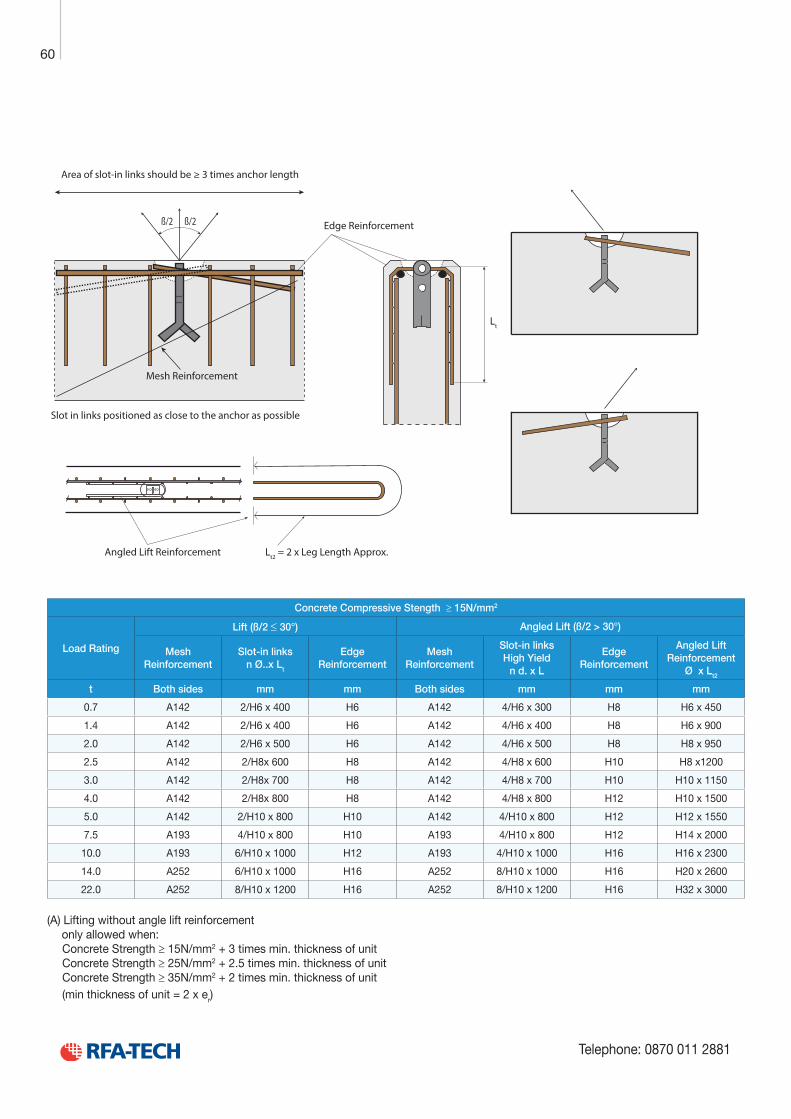
Technical Product Data
Reinforcement
All reinforcement bar used in the Startabox system is of grade B500C conforming to BS4449. Startabox is available containing 8mm to 20mm reinforcement with 12mm and 16mm being the most commonly used sizes. The rebar material is specially selected to be suitable for rebending, a prerequisite of the system, and is cut and bent to meet the requirements of BS8666, specific requirements of CARES Appendix TA2 and in line with the CARES Technical Approval on the Startabox system.
All reinforcement used is tested regularly, both in-house and independently, to ensure it continues to meet the requirements of BS4449 once rebent, offering confidence to detailers and engineers and supported by relevant and recent testing data.
Case
Startabox cases are manufactured from galvanised mild steel sheet rolled to precise dimensions. The cases are fully perforated on all faces to provide an excellent bond to the first concrete pour and provide an efficient key for the subsequent pour. The cases are annealed at specific points along the case to ease nailing when fixing to formwork. A wide range of case sizes are available to suit the rebar detail requirement.
Lid Cover
The Startabox system is fitted with a plastic tear off lid, to allow easy removal once required. The plastic lid has the advantages of no sharp edges, low weight, minimal concrete adherence and is suitable for recycling. Where necessary or requested, steel lid covers can be fitted.
End Cap Seal
Startabox cases are fitted with two easily removable plastic end cap seals. These ensure the concrete cannot enter the casing. End cap seals are suitable for recycling once removed.
Telephone: 0870 011 2881
6
Curved Startbox
60
Telephone: 0870 011 2881
Mesh Reinforcement
Edge Reinforcement
Area of slot-in links should be ≥ 3 times anchor length
Slot in links positioned as close to the anchor as possible
Lt
Angled Lift Reinforcement Lt2 = 2 x Leg Length Approx.
ß/2 ß/2
Concrete Compressive Stength ≥ 15N/mm2
Load Rating
Lift (ß/2 ≤ 30°) Angled Lift (ß/2 > 30°)
Mesh Reinforcement
Slot-in links n Ø..x Lt
Edge Reinforcement
Mesh Reinforcement
Slot-in links High Yield
n d. x L
Edge Reinforcement
Angled Lift Reinforcement
Ø x Lt2
t Both sides mm mm Both sides mm mm mm
0.7 A142 2/H6 x 400 H6 A142 4/H6 x 300 H8 H6 x 450
1.4 A142 2/H6 x 400 H6 A142 4/H6 x 400 H8 H6 x 900
2.0 A142 2/H6 x 500 H6 A142 4/H6 x 500 H8 H8 x 950
2.5 A142 2/H8x 600 H8 A142 4/H8 x 600 H10 H8 x1200
3.0 A142 2/H8x 700 H8 A142 4/H8 x 700 H10 H10 x 1150
4.0 A142 2/H8x 800 H8 A142 4/H8 x 800 H12 H10 x 1500
5.0 A142 2/H10 x 800 H10 A142 4/H10 x 800 H12 H12 x 1550
7.5 A193 4/H10 x 800 H10 A193 4/H10 x 800 H12 H14 x 2000
10.0 A193 6/H10 x 1000 H12 A193 4/H10 x 1000 H16 H16 x 2300
14.0 A252 6/H10 x 1000 H16 A252 8/H10 x 1000 H16 H20 x 2600
22.0 A252 8/H10 x 1200 H16 A252 8/H10 x 1200 H16 H32 x 3000
(A) Lifting without angle lift reinforcement only allowed when:
Concrete Strength ≥ 15N/mm2 + 3 times min. thickness of unitConcrete Strength ≥ 25N/mm2 + 2.5 times min. thickness of unitConcrete Strength ≥ 35N/mm2 + 2 times min. thickness of unit(min thickness of unit = 2 x er)
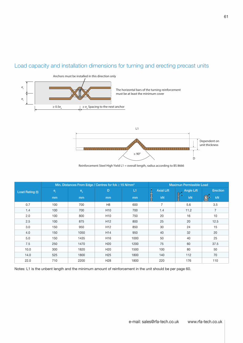
61
e-mail: [email protected] www.rfa-tech.co.uk
Load capacity and installation dimensions for turning and erecting precast units
Load Rating (t)
Min. Distances From Edge / Centres for fck ≥ 15 N/mm2 Maximun Permissible Load
er ez D L1 Axial Lift Angle Lift Erection
mm mm mm mm kN kN kN
0.7 100 700 H8 600 7 5.6 3.5
1.4 100 700 H10 700 1.4 11.2 7
2.0 100 800 H10 750 20 16 10
2.5 100 875 H12 800 25 20 12.5
3.0 150 950 H12 850 30 24 15
4.0 150 1050 H14 950 40 32 20
5.0 150 1435 H16 1000 50 40 25
7.5 250 1470 H20 1200 75 60 37.5
10.0 300 1820 H20 1500 100 80 50
14.0 525 1800 H25 1800 140 112 70
22.0 710 2200 H28 1800 220 176 110
Notes: L1 is the unbent length and the minimum amount of reinforcement in the unit should be per page 60.
≥ ez Spacing to the next anchor≥ 0.5ez
Anchors must be installed in this direction only
The horizontal bars of the turning reinforcement must be at least the minimum cover
Reinforcement Steel High Yield L1 = overall length, radius according to BS 8666
Dependent on unit thickness
D≤ 90°
L1
er
er
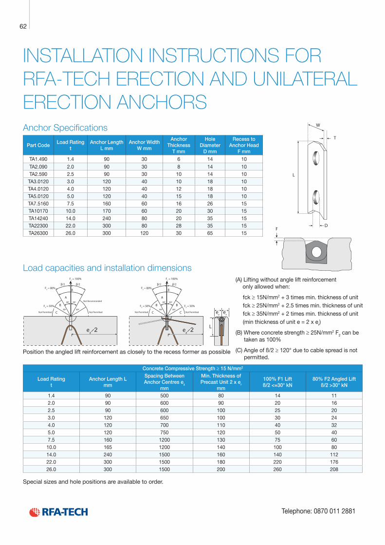
Technical Product Data
Reinforcement
All reinforcement bar used in the Startabox system is of grade B500C conforming to BS4449. Startabox is available containing 8mm to 20mm reinforcement with 12mm and 16mm being the most commonly used sizes. The rebar material is specially selected to be suitable for rebending, a prerequisite of the system, and is cut and bent to meet the requirements of BS8666, specific requirements of CARES Appendix TA2 and in line with the CARES Technical Approval on the Startabox system.
All reinforcement used is tested regularly, both in-house and independently, to ensure it continues to meet the requirements of BS4449 once rebent, offering confidence to detailers and engineers and supported by relevant and recent testing data.
Case
Startabox cases are manufactured from galvanised mild steel sheet rolled to precise dimensions. The cases are fully perforated on all faces to provide an excellent bond to the first concrete pour and provide an efficient key for the subsequent pour. The cases are annealed at specific points along the case to ease nailing when fixing to formwork. A wide range of case sizes are available to suit the rebar detail requirement.
Lid Cover
The Startabox system is fitted with a plastic tear off lid, to allow easy removal once required. The plastic lid has the advantages of no sharp edges, low weight, minimal concrete adherence and is suitable for recycling. Where necessary or requested, steel lid covers can be fitted.
End Cap Seal
Startabox cases are fitted with two easily removable plastic end cap seals. These ensure the concrete cannot enter the casing. End cap seals are suitable for recycling once removed.
Telephone: 0870 011 2881
6
Curved Startbox
62
Telephone: 0870 011 2881
INSTALLATION INSTRUCTIONS FOR RFA-TECH ERECTION AND UNILATERAL ERECTION ANCHORSAnchor Specifications
Part CodeLoad Rating
tAnchor Length
L mmAnchor Width
W mm
Anchor Thickness
T mm
Hole Diameter
D mm
Recess to Anchor Head
F mm
TA1.490 1.4 90 30 6 14 10
TA2.090 2.0 90 30 8 14 10TA2.590 2.5 90 30 10 14 10TA3.0120 3.0 120 40 10 18 10TA4.0120 4.0 120 40 12 18 10TA5.0120 5.0 120 40 15 18 10TA7.5160 7.5 160 60 16 26 15TA10170 10.0 170 60 20 30 15TA14240 14.0 240 80 20 35 15TA22300 22.0 300 80 28 35 15TA26300 26.0 300 120 30 65 15
Load capacities and installation dimensions
Concrete Compressive Strength ≥ 15 N/mm2
Load Rating t
Anchor Length L mm
Spacing Between Anchor Centres ez
mm
Min. Thickness of Precast Unit 2 x er
mm
100% F1 Lift ß/2 <=30° kN
80% F2 Angled Lift ß/2 >30° kN
1.4 90 500 80 14 112.0 90 600 90 20 162.5 90 600 100 25 203.0 120 650 100 30 244.0 120 700 110 40 325.0 120 750 120 50 407.5 160 1200 130 75 60
10.0 165 1200 140 100 8014.0 240 1500 160 140 11222.0 300 1500 180 220 17626.0 300 1500 200 260 208
Special sizes and hole positions are available to order.
F
W
D
L
T
er er
L ez ̷ 2 ez ̷ 2
30º
30º
30º
30º
F1 = 100%
F2 = 80%
F3 = 50% F3 = 50%
β/2
β
β/2
C C
B B
A
Not Permitted Not Permitted
30º
30º
30º
30º
F1 = 100%
F2 = 80%
F3 = 50%
β/2
β
β/2
C
B
A
Not Permitted Not Permitted
Not Recommended
Position the angled lift reinforcement as closely to the recess former as possible
(A) Lifting without angle lift reinforcement only allowed when:
fck ≥ 15N/mm2 + 3 times min. thickness of unitfck ≥ 25N/mm2 + 2.5 times min. thickness of unitfck ≥ 35N/mm2 + 2 times min. thickness of unit(min thickness of unit e = 2 x er)
(B) Where concrete strength ≥ 25N/mm2 F2 can be taken as 100%
(C) Angle of ß/2 ≥ 120° due to cable spread is not permitted.

63
e-mail: [email protected] www.rfa-tech.co.uk
Reinforcement Required
Concrete Compressive Strength ≥ 15 N/mm2
Load Rating
Axial Lift (ß/2<= 30°) Angled Lift (ß/2> 30°)
Mesh Reinforce-
ment
Both Sides of the Anchor
Slot-in links No. / Ø x L1
Edge Reinforce-
ment
Reinforce-ment Tails
No. / Ø x D2
(2)
Mesh Reinforce-
ment
Both Sides of the Anchor
Slot-in links No. / Ø x L1
Edge Reinforce-
ment
(2) Reinforce- ment tails
No. / Ø x D2
(1) Angled Lift
Reinforce- ment
No. / Ø x L2
t mm mm mm mm mm mm mm
1.4 A142 2/H6 x 400 H6 1/H10 x 650 A142 4/H6 x 400 H8 1/H10 x 650 H6 x 900
2.0 A142 2/H6 x 500 H6 1/H12 x 800 A142 4/H6 x 500 H8 1/H10 x 800 H8 x 950
2.5 A142 2/H8 x 600 H6 1/H12 x 1000 A142 4/H8 x 600 H10 1/H12 x 1000 H8 x 1200
3.0 A142 2/H8 x 700 H8 1/H16 x 1000 A142 4/H8 x 700 H10 1/H16 x 1000 H10 x 1150
4.0 A142 2/H8 x 700 H8 1/H16 x 1200 A142 4/H8 x 800 H12 1/H16 x 1200 H10 x 1500
5.0 A142 2/H8 x 800 H8 1/H16 x 1500 A142 4/H10 x 800 H12 1/H16 x 1500 H12 x 1550
7.5 A142 2/H10 x 800 H10 1/H20 x 1750 A142 4/H10 x 800 H12 1/H20 x 1750 H16 x 2000
10.0 A142 4/H10 x 800 H12 1/H25 x 1850 A142 4H10 x 1000 H16 1/H25 x 1850 H16 x 2300
14.0 A142 4/H0 x 1000 H16 1/H28 x 2350 A142 8/H10 x 1000 H16 1/H28 x 2350 H20 x 2600
22.0 A142 4/H12 x 1200 H16 1/H28 x 3000 A142 8/H10 x 1200 H16 1/H28 x 3000 H25 x 3000
26.0 A142 6/H12 x 1200 H16 2/H28 x 3050 A142 8/H12 x 1200 H16 2/H28 x 3050 H28 x 3450
ß/2
Area of slot-in links should be ≥ 3 times anchor length
Slot-in links positioned as close to the anchor as possible
L 1MeshReinforcement
≤ 30°
L2
D2
Angled Lift Reinforcement as close as possible to recess former
L2 = 2 x Leg Length Approx.
(1) Lifting without angle lift reinforcement only allowed when:
Concrete Strength ≥ 15N/mm2 and 3.0 times min. thickness of unit
Concrete Strength ≥ 25N/mm2 and 2.5 times min. thickness of unit
Concrete Strength ≥ 35N/mm2 and 2 times min. thickness of unit
(min thickness of unit = 2 x er)
(2) L2 can be reduced in length for increased concrete strength as follows: 1. Concrete Strength ≥ 25N/mm2 = L2 x 0.8 2. Concrete Strength ≥ 35N/mm2 = L2 x 0.65
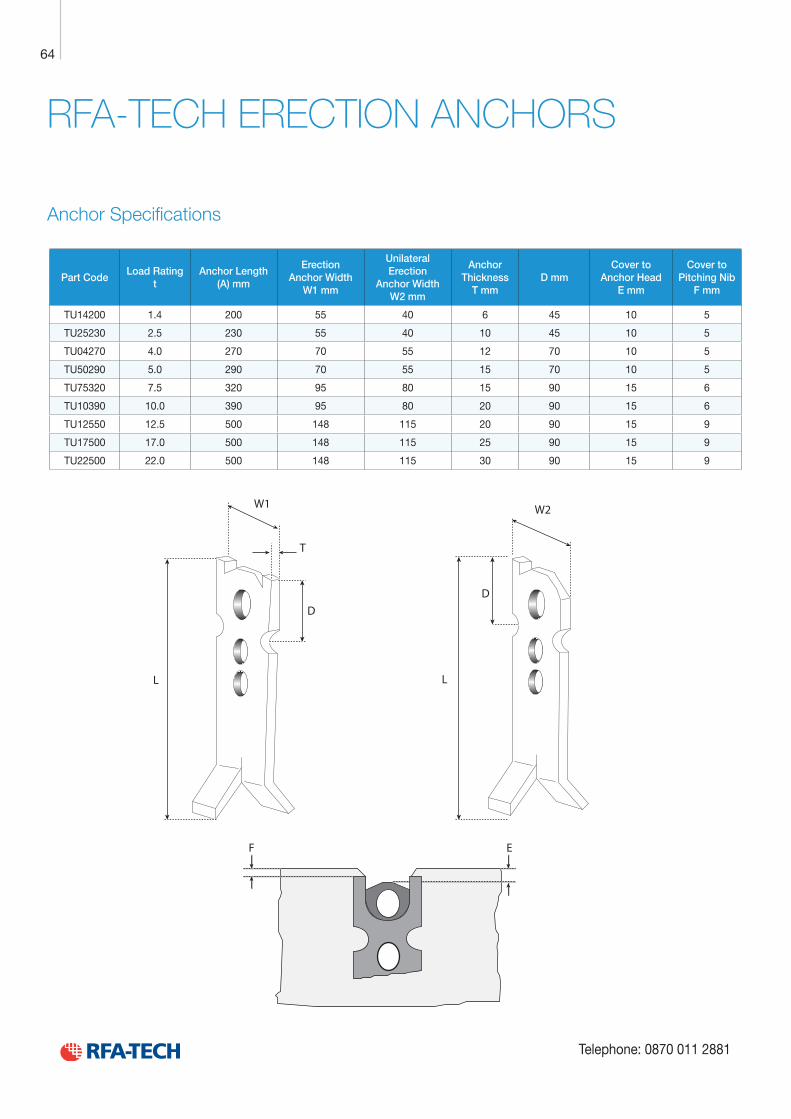
Technical Product Data
Reinforcement
All reinforcement bar used in the Startabox system is of grade B500C conforming to BS4449. Startabox is available containing 8mm to 20mm reinforcement with 12mm and 16mm being the most commonly used sizes. The rebar material is specially selected to be suitable for rebending, a prerequisite of the system, and is cut and bent to meet the requirements of BS8666, specific requirements of CARES Appendix TA2 and in line with the CARES Technical Approval on the Startabox system.
All reinforcement used is tested regularly, both in-house and independently, to ensure it continues to meet the requirements of BS4449 once rebent, offering confidence to detailers and engineers and supported by relevant and recent testing data.
Case
Startabox cases are manufactured from galvanised mild steel sheet rolled to precise dimensions. The cases are fully perforated on all faces to provide an excellent bond to the first concrete pour and provide an efficient key for the subsequent pour. The cases are annealed at specific points along the case to ease nailing when fixing to formwork. A wide range of case sizes are available to suit the rebar detail requirement.
Lid Cover
The Startabox system is fitted with a plastic tear off lid, to allow easy removal once required. The plastic lid has the advantages of no sharp edges, low weight, minimal concrete adherence and is suitable for recycling. Where necessary or requested, steel lid covers can be fitted.
End Cap Seal
Startabox cases are fitted with two easily removable plastic end cap seals. These ensure the concrete cannot enter the casing. End cap seals are suitable for recycling once removed.
Telephone: 0870 011 2881
6
Curved Startbox
64
Telephone: 0870 011 2881
RFA-TECH ERECTION ANCHORS
Anchor Specifications
Part CodeLoad Rating
tAnchor Length
(A) mm
Erection Anchor Width
W1 mm
Unilateral Erection
Anchor Width W2 mm
Anchor Thickness
T mmD mm
Cover to Anchor Head
E mm
Cover to Pitching Nib
F mm
TU14200 1.4 200 55 40 6 45 10 5
TU25230 2.5 230 55 40 10 45 10 5
TU04270 4.0 270 70 55 12 70 10 5
TU50290 5.0 290 70 55 15 70 10 5
TU75320 7.5 320 95 80 15 90 15 6
TU10390 10.0 390 95 80 20 90 15 6
TU12550 12.5 500 148 115 20 90 15 9
TU17500 17.0 500 148 115 25 90 15 9
TU22500 22.0 500 148 115 30 90 15 9
L
W1
L
W2
T
D
F E
D
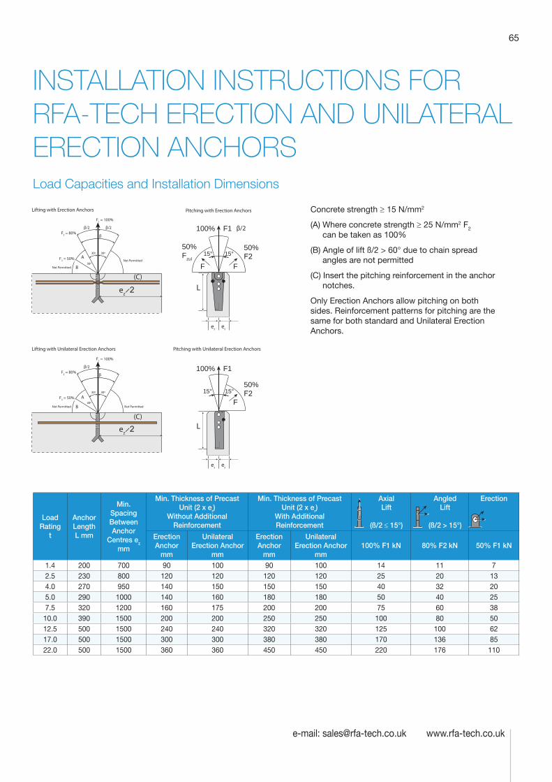
65
e-mail: [email protected] www.rfa-tech.co.uk
INSTALLATION INSTRUCTIONS FOR RFA-TECH ERECTION AND UNILATERAL ERECTION ANCHORSLoad Capacities and Installation Dimensions
Load Rating
t
Anchor Length L mm
Min. Spacing Between Anchor
Centres ez mm
Min. Thickness of Precast Unit (2 x er)
Without Additional Reinforcement
Min. Thickness of Precast Unit (2 x er)
With Additional Reinforcement
Axial Lift
(ß/2 ≤ 15°)
Angled Lift
(ß/2 > 15°)
Erection
Erection Anchor
mm
Unilateral Erection Anchor
mm
Erection Anchor
mm
Unilateral Erection Anchor
mm100% F1 kN 80% F2 kN 50% F1 kN
1.4 200 700 90 100 90 100 14 11 72.5 230 800 120 120 120 120 25 20 134.0 270 950 140 150 150 150 40 32 205.0 290 1000 140 160 180 180 50 40 257.5 320 1200 160 175 200 200 75 60 3810.0 390 1500 200 200 250 250 100 80 5012.5 500 1500 240 240 320 320 125 100 6217.0 500 1500 300 300 380 380 170 136 8522.0 500 1500 360 360 450 450 220 176 110
Concrete strength ≥ 15 N/mm2
(A) Where concrete strength ≥ 25 N/mm2 F2 can be taken as 100%
(B) Angle of lift ß/2 > 60° due to chain spread angles are not permitted
(C) Insert the pitching reinforcement in the anchor notches.
Only Erection Anchors allow pitching on both sides. Reinforcement patterns for pitching are the same for both standard and Unilateral Erection Anchors.
ez ̷ 2
15° 15°50% Fzul
F F
L
er er
Lifting with Erection Anchors Pitching with Erection Anchors
ez ̷ 2(C)
100% F1
100% F1
15° 15°50% F2
50% F2
F
L
er er
Lifting with Unilateral Erection Anchors Pitching with Unilateral Erection Anchors
(C)
30º30º
30º
F1 = 100%
F2 = 80%
F3 = 50%
β/2 β/2β
β/2
B
A
Not Permitted
Not Permitted
30º30º
30º
F1 = 100%
F2 = 80%
F3 = 50%
β
β/2
B
A
Not Permitted Not Permitted
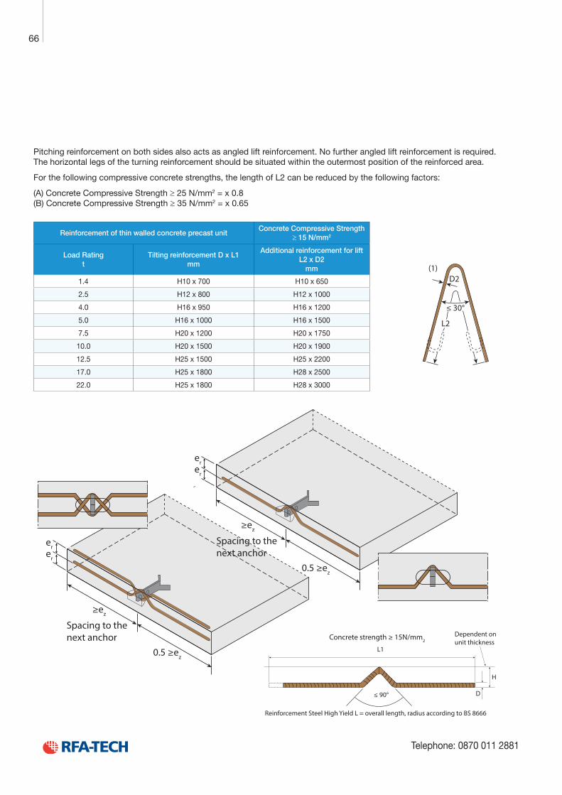
Technical Product Data
Reinforcement
All reinforcement bar used in the Startabox system is of grade B500C conforming to BS4449. Startabox is available containing 8mm to 20mm reinforcement with 12mm and 16mm being the most commonly used sizes. The rebar material is specially selected to be suitable for rebending, a prerequisite of the system, and is cut and bent to meet the requirements of BS8666, specific requirements of CARES Appendix TA2 and in line with the CARES Technical Approval on the Startabox system.
All reinforcement used is tested regularly, both in-house and independently, to ensure it continues to meet the requirements of BS4449 once rebent, offering confidence to detailers and engineers and supported by relevant and recent testing data.
Case
Startabox cases are manufactured from galvanised mild steel sheet rolled to precise dimensions. The cases are fully perforated on all faces to provide an excellent bond to the first concrete pour and provide an efficient key for the subsequent pour. The cases are annealed at specific points along the case to ease nailing when fixing to formwork. A wide range of case sizes are available to suit the rebar detail requirement.
Lid Cover
The Startabox system is fitted with a plastic tear off lid, to allow easy removal once required. The plastic lid has the advantages of no sharp edges, low weight, minimal concrete adherence and is suitable for recycling. Where necessary or requested, steel lid covers can be fitted.
End Cap Seal
Startabox cases are fitted with two easily removable plastic end cap seals. These ensure the concrete cannot enter the casing. End cap seals are suitable for recycling once removed.
Telephone: 0870 011 2881
6
Curved Startbox
66
Telephone: 0870 011 2881
Pitching reinforcement on both sides also acts as angled lift reinforcement. No further angled lift reinforcement is required. The horizontal legs of the turning reinforcement should be situated within the outermost position of the reinforced area.
For the following compressive concrete strengths, the length of L2 can be reduced by the following factors:
(A) Concrete Compressive Strength ≥ 25 N/mm2 = x 0.8 (B) Concrete Compressive Strength ≥ 35 N/mm2 = x 0.65
Concrete strength ≥ 15N/mm2
Reinforcement Steel High Yield L = overall length, radius according to BS 8666
Dependent on unit thickness
D
H
≤ 90°
L1
≤ 30°
L2
D2(1)
Reinforcement of thin walled concrete precast unitConcrete Compressive Strength
≥ 15 N/mm2
Load Rating t
Tilting reinforcement D x L1 mm
Additional reinforcement for lift L2 x D2
mm
1.4 H10 x 700 H10 x 650
2.5 H12 x 800 H12 x 1000
4.0 H16 x 950 H16 x 1200
5.0 H16 x 1000 H16 x 1500
7.5 H20 x 1200 H20 x 1750
10.0 H20 x 1500 H20 x 1900
12.5 H25 x 1500 H25 x 2200
17.0 H25 x 1800 H28 x 2500
22.0 H25 x 1800 H28 x 3000
erer
≥ez
Spacing to the next anchor
0.5 ≥ez
erer
≥ez
0.5 ≥ez
Spacing to the next anchor
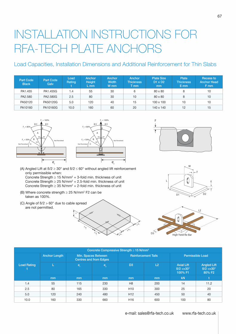
67
e-mail: [email protected] www.rfa-tech.co.uk
INSTALLATION INSTRUCTIONS FOR RFA-TECH PLATE ANCHORSLoad Capacities, Installation Dimensions and Additional Reinforcement for Thin Slabs
Part Code Black
Part Code Galv
Load Rating
t
Anchor Height L mm
Anchor Width W mm
Anchor Thickness
T mm
Plate Size D1 x D2
mm
Plate Thickness
E mm
Recess to Anchor Head
F mm
PA1.455 PA1.455G 1.4 55 30 6 80 x 80 8 10
PA2.580 PA2.580G 2.5 80 30 10 80 x 80 8 10
PA50120 PA50120G 5.0 120 40 15 100 x 100 10 10
PA10160 PA10160G 10.0 160 60 20 140 x 140 12 15
Concrete Compressive Strength ≥ 15 N/mm2
Load Rating t
Anchor Length Min. Spaces Between Centres and from Edges
Reinforcement Tails Permissible Load
L er ez D3 L2 Axial Lift ß/2 <=30° 100% F1
Angled Lift ß/2 <=30° 80% F2
mm mm mm mm mm kN t
1.4 55 115 230 H8 200 14 11.2
2.5 80 165 330 H10 300 25 20
5.0 120 240 480 H12 450 50 40
10.0 160 330 660 H16 600 100 80
L
W
T
E
D2
D3
L2
High Yield Re-Bar
D1
er er
30º30º
30º
F1 = 100%
F2 = 80%
F3 = 50%
β/2
β
β/2
C
B
A
Not Permitted
Not Permitted
30º30º
30º
F1 = 100%
F2 = 80%
F3 = 50%
β/2
β
β/2
C
B
A
Not Permitted
Not Permitted
(A) Angled Lift at ß/2 ≥ 30° and ß/2 ≤ 60° without angled lift reinforcement only permissible when: Concrete Strength ≥ 15 N/mm2 + 3-fold min. thickness of unit Concrete Strength ≥ 25 N/mm2 + 2.5-fold min. thickness of unit Concrete Strength ≥ 35 N/mm2 + 2-fold min. thickness of unit
(B) Where concrete strength ≥ 25 N/mm2 F2 can be taken as 100%.
(C) Angle of ß/2 > 60° due to cable spread are not permitted.
F
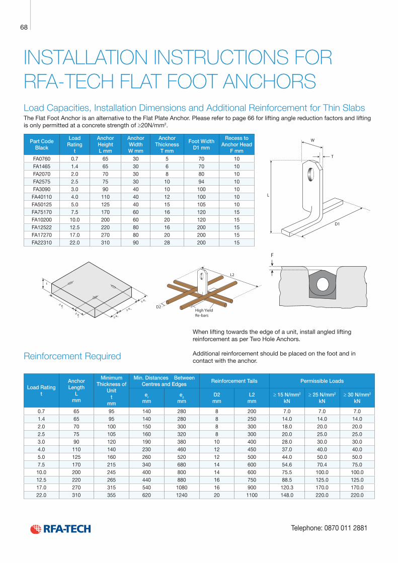
Technical Product Data
Reinforcement
All reinforcement bar used in the Startabox system is of grade B500C conforming to BS4449. Startabox is available containing 8mm to 20mm reinforcement with 12mm and 16mm being the most commonly used sizes. The rebar material is specially selected to be suitable for rebending, a prerequisite of the system, and is cut and bent to meet the requirements of BS8666, specific requirements of CARES Appendix TA2 and in line with the CARES Technical Approval on the Startabox system.
All reinforcement used is tested regularly, both in-house and independently, to ensure it continues to meet the requirements of BS4449 once rebent, offering confidence to detailers and engineers and supported by relevant and recent testing data.
Case
Startabox cases are manufactured from galvanised mild steel sheet rolled to precise dimensions. The cases are fully perforated on all faces to provide an excellent bond to the first concrete pour and provide an efficient key for the subsequent pour. The cases are annealed at specific points along the case to ease nailing when fixing to formwork. A wide range of case sizes are available to suit the rebar detail requirement.
Lid Cover
The Startabox system is fitted with a plastic tear off lid, to allow easy removal once required. The plastic lid has the advantages of no sharp edges, low weight, minimal concrete adherence and is suitable for recycling. Where necessary or requested, steel lid covers can be fitted.
End Cap Seal
Startabox cases are fitted with two easily removable plastic end cap seals. These ensure the concrete cannot enter the casing. End cap seals are suitable for recycling once removed.
Telephone: 0870 011 2881
6
Curved Startbox
68
Telephone: 0870 011 2881
INSTALLATION INSTRUCTIONS FOR RFA-TECH FLAT FOOT ANCHORSLoad Capacities, Installation Dimensions and Additional Reinforcement for Thin Slabs The Flat Foot Anchor is an alternative to the Flat Plate Anchor. Please refer to page 66 for lifting angle reduction factors and lifting is only permitted at a concrete strength of ≥20N/mm2.
Part Code Black
Load Rating
t
Anchor Height L mm
Anchor Width W mm
Anchor Thickness
T mm
Foot Width D1 mm
Recess to Anchor Head
F mm
FA0760 0.7 65 30 5 70 10FA1465 1.4 65 30 6 70 10FA2070 2.0 70 30 8 80 10FA2575 2.5 75 30 10 94 10FA3090 3.0 90 40 10 100 10FA40110 4.0 110 40 12 100 10FA50125 5.0 125 40 15 105 10FA75170 7.5 170 60 16 120 15FA10200 10.0 200 60 20 120 15FA12522 12.5 220 80 16 200 15FA17270 17.0 270 80 20 200 15FA22310 22.0 310 90 28 200 15
Reinforcement Required
Load Rating t
Anchor Length
L mm
Minimum Thickness of
Unit t
mm
Min. Distances Between Centres and Edges
Reinforcement Tails Permissible Loads
er
mmez
mmD2 mm
L2 mm
≥ 15 N/mm2
kN≥ 25 N/mm2
kN≥ 30 N/mm2
kN
0.7 65 95 140 280 8 200 7.0 7.0 7.01.4 65 95 140 280 8 250 14.0 14.0 14.02.0 70 100 150 300 8 300 18.0 20.0 20.02.5 75 105 160 320 8 300 20.0 25.0 25.03.0 90 120 190 380 10 400 28.0 30.0 30.04.0 110 140 230 460 12 450 37.0 40.0 40.05.0 125 160 260 520 12 500 44.0 50.0 50.07.5 170 215 340 680 14 600 54.6 70.4 75.0
10.0 200 245 400 800 14 600 75.5 100.0 100.012.5 220 265 440 880 16 750 88.5 125.0 125.017.0 270 315 540 1080 16 900 120.3 170.0 170.022.0 310 355 620 1240 20 1100 148.0 220.0 220.0
D1
W
T
L
D2High YieldRe-bars
L2
When lifting towards the edge of a unit, install angled lifting reinforcement as per Two Hole Anchors. Additional reinforcement should be placed on the foot and in contact with the anchor.
F
D1
W
T
L
D2High YieldRe-bars
L2
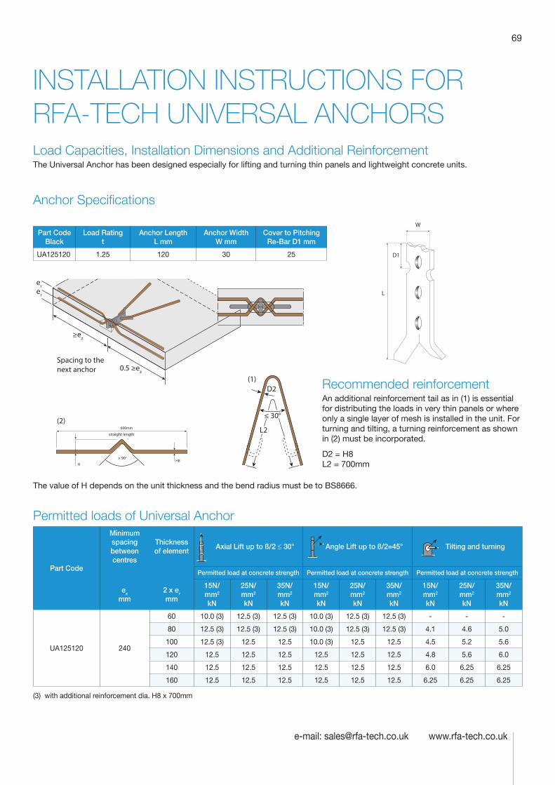
69
e-mail: [email protected] www.rfa-tech.co.uk
INSTALLATION INSTRUCTIONS FOR RFA-TECH UNIVERSAL ANCHORSLoad Capacities, Installation Dimensions and Additional Reinforcement The Universal Anchor has been designed especially for lifting and turning thin panels and lightweight concrete units.
Anchor Specifications
Part Code Black
Load Rating t
Anchor Length L mm
Anchor Width W mm
Cover to Pitching Re-Bar D1 mm
UA125120 1.25 120 30 25
W
D1
L
Recommended reinforcementAn additional reinforcement tail as in (1) is essential for distributing the loads in very thin panels or where only a single layer of mesh is installed in the unit. For turning and tilting, a turning reinforcement as shown in (2) must be incorporated.
D2 = H8 L2 = 700mm
Permitted loads of Universal Anchor
Part Code
Minimum spacing between centres
Thickness of element
Axial Lift up to ß/2 ≤ 30° Angle Lift up to ß/2=45° Tilting and turning
Permitted load at concrete strength Permitted load at concrete strength Permitted load at concrete strength
ez mm
2 x er mm
15N/mm2
kN
25N/mm2
kN
35N/mm2
kN
15N/mm2
kN
25N/mm2
kN
35N/mm2
kN
15N/mm2
kN
25N/mm2
kN
35N/mm2
kN
UA125120 240
60 10.0 (3) 12.5 (3) 12.5 (3) 10.0 (3) 12.5 (3) 12.5 (3) - - -
80 12.5 (3) 12.5 (3) 12.5 (3) 10.0 (3) 12.5 (3) 12.5 (3) 4.1 4.6 5.0
100 12.5 (3) 12.5 12.5 10.0 (3) 12.5 12.5 4.5 5.2 5.6
120 12.5 12.5 12.5 12.5 12.5 12.5 4.8 5.6 6.0
140 12.5 12.5 12.5 12.5 12.5 12.5 6.0 6.25 6.25
160 12.5 12.5 12.5 12.5 12.5 12.5 6.25 6.25 6.25
(3) with additional reinforcement dia. H8 x 700mm
≤ 30°
L2
D2
straight length
≤ 90°
600mm
H8H
(1)
(2)
erer
≥ez
Spacing to the next anchor 0.5 ≥ez
The value of H depends on the unit thickness and the bend radius must be to BS8666.
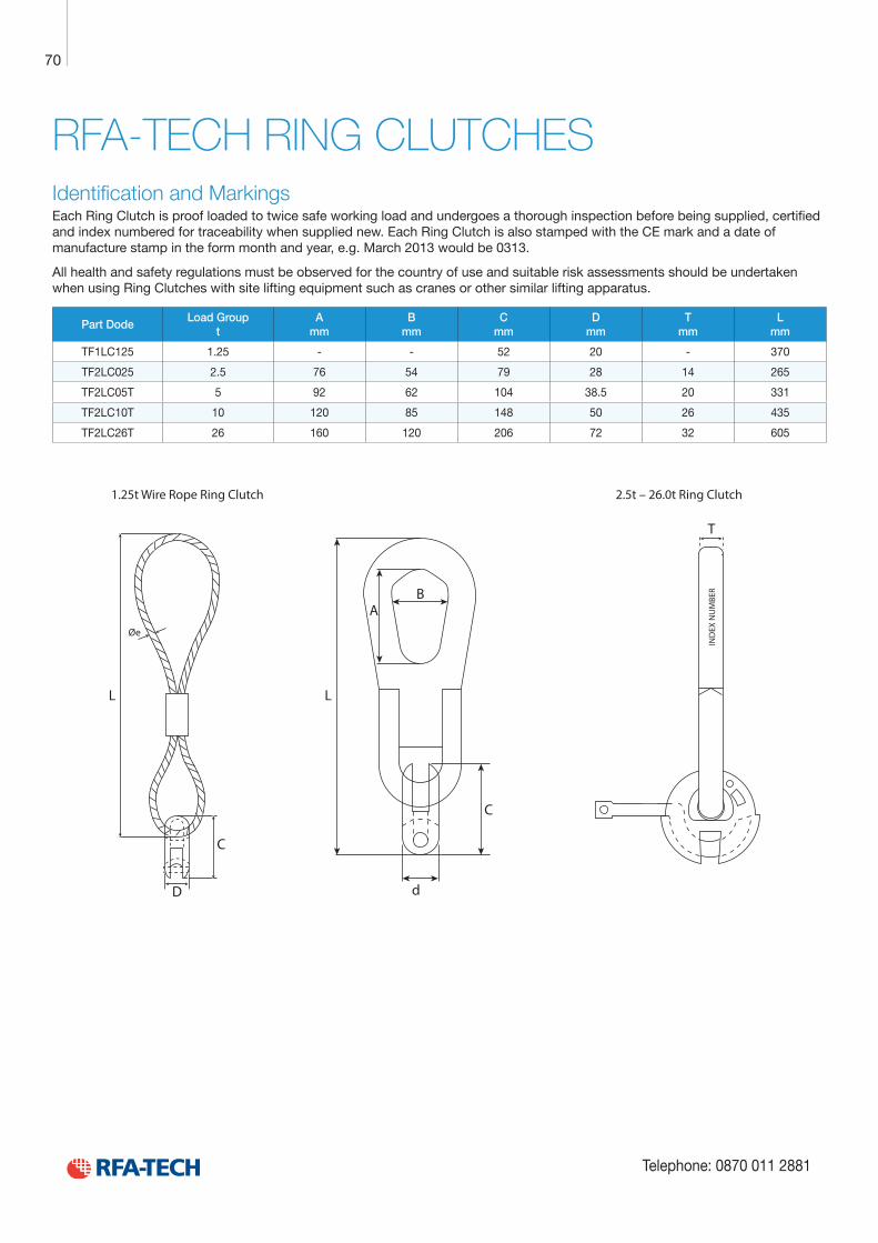
Technical Product Data
Reinforcement
All reinforcement bar used in the Startabox system is of grade B500C conforming to BS4449. Startabox is available containing 8mm to 20mm reinforcement with 12mm and 16mm being the most commonly used sizes. The rebar material is specially selected to be suitable for rebending, a prerequisite of the system, and is cut and bent to meet the requirements of BS8666, specific requirements of CARES Appendix TA2 and in line with the CARES Technical Approval on the Startabox system.
All reinforcement used is tested regularly, both in-house and independently, to ensure it continues to meet the requirements of BS4449 once rebent, offering confidence to detailers and engineers and supported by relevant and recent testing data.
Case
Startabox cases are manufactured from galvanised mild steel sheet rolled to precise dimensions. The cases are fully perforated on all faces to provide an excellent bond to the first concrete pour and provide an efficient key for the subsequent pour. The cases are annealed at specific points along the case to ease nailing when fixing to formwork. A wide range of case sizes are available to suit the rebar detail requirement.
Lid Cover
The Startabox system is fitted with a plastic tear off lid, to allow easy removal once required. The plastic lid has the advantages of no sharp edges, low weight, minimal concrete adherence and is suitable for recycling. Where necessary or requested, steel lid covers can be fitted.
End Cap Seal
Startabox cases are fitted with two easily removable plastic end cap seals. These ensure the concrete cannot enter the casing. End cap seals are suitable for recycling once removed.
Telephone: 0870 011 2881
6
Curved Startbox
70
Telephone: 0870 011 2881
RFA-TECH RING CLUTCHESIdentification and Markings Each Ring Clutch is proof loaded to twice safe working load and undergoes a thorough inspection before being supplied, certified and index numbered for traceability when supplied new. Each Ring Clutch is also stamped with the CE mark and a date of manufacture stamp in the form month and year, e.g. March 2013 would be 0313.
All health and safety regulations must be observed for the country of use and suitable risk assessments should be undertaken when using Ring Clutches with site lifting equipment such as cranes or other similar lifting apparatus.
Part DodeLoad Group
tA
mmB
mmC
mmD
mmT
mmL
mm
TF1LC125 1.25 - - 52 20 - 370
TF2LC025 2.5 76 54 79 28 14 265
TF2LC05T 5 92 62 104 38.5 20 331
TF2LC10T 10 120 85 148 50 26 435
TF2LC26T 26 160 120 206 72 32 605
C
LL
Øe
AB
d
T
C
D
1.25t Wire Rope Ring Clutch 2.5t – 26.0t Ring Clutch
IND
EX N
UM
BER
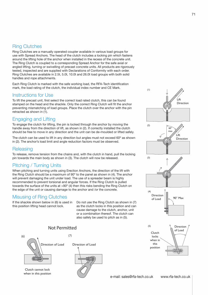
71
e-mail: [email protected] www.rfa-tech.co.uk
Ring Clutches Ring Clutches are a manually operated coupler available in various load groups for use with Spread Anchors. The head of the clutch includes a locking pin which fastens around the lifting hole of the anchor when installed in the recess of the concrete unit. The Ring Clutch is coupled to a corresponding Spread Anchor for the safe axial or angled lifting, turning or swivelling of precast concrete units. All products are rigorously tested, inspected and are supplied with Declarations of Conformity with each order. Ring Clutches are available in 2.5t, 5.0t, 10.0t and 26.0t load groups with both solid handles and rope attachments.
Each Ring Clutch is marked with the safe working load, the RFA-Tech identification mark, the load rating of the clutch, the individual index number and CE Mark.
Instructions for UseTo lift the precast unit, first select the correct load rated clutch, this can be found stamped on the head and the shackle. Only the correct Ring Clutch will fit the anchor preventing mismatching of load groups. Place the clutch over the anchor with the pin retracted as shown in (1).
Engaging and LiftingTo engage the clutch for lifting, the pin is locked through the anchor by moving the handle away from the direction of lift, as shown in (2). If correctly installed the clutch should be free to move in any direction and the unit can be de-moulded or lifted safely.
The clutch can be used to lift in any direction but angles must not exceed 60º as shown in (2). The anchor’s load limit and angle reduction factors must be observed.
ReleasingTo release, remove tension from the chains and, with the clutch in hand, pull the locking pin towards the main body as shown in (3). The clutch will now be released.
Pitching / Turning UnitsWhen pitching and turning units using Erection Anchors, the direction of the lift with the Ring Clutch should be a maximum of 90º to the panel as shown in (4). The anchor will prevent damaging the unit under load. The use of a spreader beam is highly recommended to prevent torsional and angular forces. If the Ring Clutch is pulled towards the surface of the units at >90º (4) then this risks bending the Ring Clutch on the edge of the unit or causing damage to the anchor and /or the concrete.
Misusing of Ring ClutchesIf the shackle shown below in (6) is used in this position lifting head cannot lock.
Do not use the Ring Clutch as shown in (7) as the clutch locks in this position and can cause damage to the clutch, anchor, unit or a combination thereof. The clutch can also safely be used to pitch as in (5).
LiftDirection
LiftDirection
60° max
(1)
(2)
(3)
(4)
(5)
RFA
90° MaxDirection of Load
Clutch locks
when in this
position
Direction of Load
Direction of Load Direction of Load
Clutch cannot lock when in this position
(6) (7)
Not Permitted
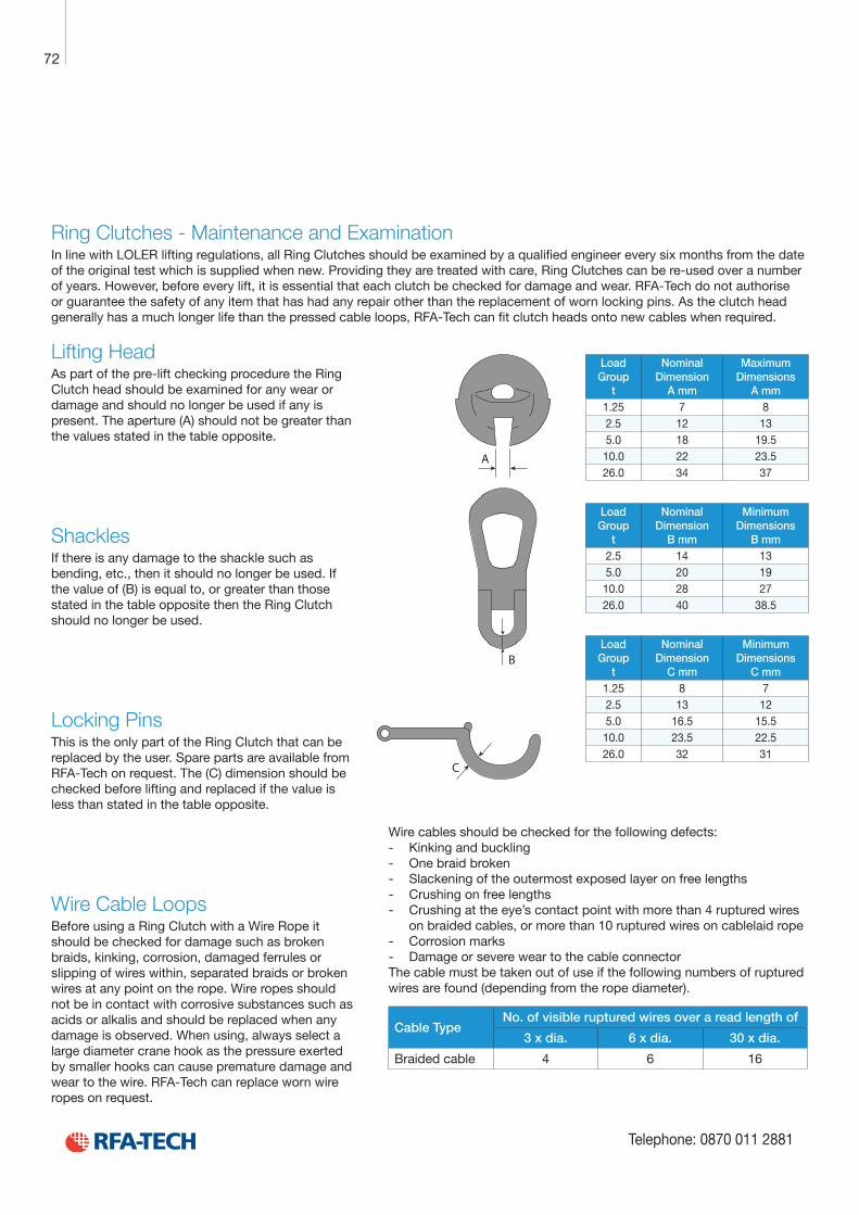
Technical Product Data
Reinforcement
All reinforcement bar used in the Startabox system is of grade B500C conforming to BS4449. Startabox is available containing 8mm to 20mm reinforcement with 12mm and 16mm being the most commonly used sizes. The rebar material is specially selected to be suitable for rebending, a prerequisite of the system, and is cut and bent to meet the requirements of BS8666, specific requirements of CARES Appendix TA2 and in line with the CARES Technical Approval on the Startabox system.
All reinforcement used is tested regularly, both in-house and independently, to ensure it continues to meet the requirements of BS4449 once rebent, offering confidence to detailers and engineers and supported by relevant and recent testing data.
Case
Startabox cases are manufactured from galvanised mild steel sheet rolled to precise dimensions. The cases are fully perforated on all faces to provide an excellent bond to the first concrete pour and provide an efficient key for the subsequent pour. The cases are annealed at specific points along the case to ease nailing when fixing to formwork. A wide range of case sizes are available to suit the rebar detail requirement.
Lid Cover
The Startabox system is fitted with a plastic tear off lid, to allow easy removal once required. The plastic lid has the advantages of no sharp edges, low weight, minimal concrete adherence and is suitable for recycling. Where necessary or requested, steel lid covers can be fitted.
End Cap Seal
Startabox cases are fitted with two easily removable plastic end cap seals. These ensure the concrete cannot enter the casing. End cap seals are suitable for recycling once removed.
Telephone: 0870 011 2881
6
Curved Startbox
72
Telephone: 0870 011 2881
Ring Clutches - Maintenance and Examination In line with LOLER lifting regulations, all Ring Clutches should be examined by a qualified engineer every six months from the date of the original test which is supplied when new. Providing they are treated with care, Ring Clutches can be re-used over a number of years. However, before every lift, it is essential that each clutch be checked for damage and wear. RFA-Tech do not authorise or guarantee the safety of any item that has had any repair other than the replacement of worn locking pins. As the clutch head generally has a much longer life than the pressed cable loops, RFA-Tech can fit clutch heads onto new cables when required.
B
C
A
Lifting HeadAs part of the pre-lift checking procedure the Ring Clutch head should be examined for any wear or damage and should no longer be used if any is present. The aperture (A) should not be greater than the values stated in the table opposite.
ShacklesIf there is any damage to the shackle such as bending, etc., then it should no longer be used. If the value of (B) is equal to, or greater than those stated in the table opposite then the Ring Clutch should no longer be used.
Locking PinsThis is the only part of the Ring Clutch that can be replaced by the user. Spare parts are available from RFA-Tech on request. The (C) dimension should be checked before lifting and replaced if the value is less than stated in the table opposite.
Wire Cable LoopsBefore using a Ring Clutch with a Wire Rope it should be checked for damage such as broken braids, kinking, corrosion, damaged ferrules or slipping of wires within, separated braids or broken wires at any point on the rope. Wire ropes should not be in contact with corrosive substances such as acids or alkalis and should be replaced when any damage is observed. When using, always select a large diameter crane hook as the pressure exerted by smaller hooks can cause premature damage and wear to the wire. RFA-Tech can replace worn wire ropes on request.
Wire cables should be checked for the following defects: - Kinking and buckling - One braid broken - Slackening of the outermost exposed layer on free lengths - Crushing on free lengths - Crushing at the eye’s contact point with more than 4 ruptured wires
on braided cables, or more than 10 ruptured wires on cablelaid rope - Corrosion marks - Damage or severe wear to the cable connector
The cable must be taken out of use if the following numbers of ruptured wires are found (depending from the rope diameter).
Cable TypeNo. of visible ruptured wires over a read length of
3 x dia. 6 x dia. 30 x dia.
Braided cable 4 6 16
Load Group
t
Nominal Dimension
A mm
Maximum Dimensions
A mm1.25 7 82.5 12 135.0 18 19.510.0 22 23.526.0 34 37
Load Group
t
Nominal Dimension
B mm
Minimum Dimensions
B mm2.5 14 135.0 20 1910.0 28 2726.0 40 38.5
Load Group
t
Nominal Dimension
C mm
Minimum Dimensions
C mm1.25 8 72.5 13 125.0 16.5 15.510.0 23.5 22.526.0 32 31
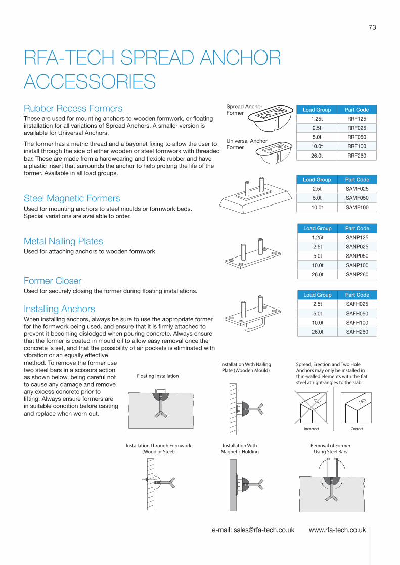
73
e-mail: [email protected] www.rfa-tech.co.uk
RFA-TECH SPREAD ANCHOR ACCESSORIES
Incorrect Correct
Floating Installation
Installation Through Formwork(Wood or Steel)
Installation With NailingPlate (Wooden Mould)
Installation WithMagnetic Holding
Removal of Former Using Steel Bars
Spread, Erection and Two Hole Anchors may only be installed in thin-walled elements with the �at steel at right-angles to the slab.
Spread Anchor Former
Universal Anchor Former
Rubber Recess FormersThese are used for mounting anchors to wooden formwork, or floating installation for all variations of Spread Anchors. A smaller version is available for Universal Anchors.
The former has a metric thread and a bayonet fixing to allow the user to install through the side of either wooden or steel formwork with threaded bar. These are made from a hardwearing and flexible rubber and have a plastic insert that surrounds the anchor to help prolong the life of the former. Available in all load groups.
Steel Magnetic FormersUsed for mounting anchors to steel moulds or formwork beds. Special variations are available to order.
Metal Nailing PlatesUsed for attaching anchors to wooden formwork.
Former CloserUsed for securely closing the former during floating installations.
Installing AnchorsWhen installing anchors, always be sure to use the appropriate former for the formwork being used, and ensure that it is firmly attached to prevent it becoming dislodged when pouring concrete. Always ensure that the former is coated in mould oil to allow easy removal once the concrete is set, and that the possibility of air pockets is eliminated with vibration or an equally effective method. To remove the former use two steel bars in a scissors action as shown below, being careful not to cause any damage and remove any excess concrete prior to lifting. Always ensure formers are in suitable condition before casting and replace when worn out.
Load Group Part Code
1.25t RRF125
2.5t RRF025
5.0t RRF050
10.0t RRF100
26.0t RRF260
Load Group Part Code
2.5t SAMF025
5.0t SAMF050
10.0t SAMF100
Load Group Part Code
1.25t SANP125
2.5t SANP025
5.0t SANP050
10.0t SANP100
26.0t SANP260
Load Group Part Code
2.5t SAFH025
5.0t SAFH050
10.0t SAFH100
26.0t SAFH260

Technical Product Data
Reinforcement
All reinforcement bar used in the Startabox system is of grade B500C conforming to BS4449. Startabox is available containing 8mm to 20mm reinforcement with 12mm and 16mm being the most commonly used sizes. The rebar material is specially selected to be suitable for rebending, a prerequisite of the system, and is cut and bent to meet the requirements of BS8666, specific requirements of CARES Appendix TA2 and in line with the CARES Technical Approval on the Startabox system.
All reinforcement used is tested regularly, both in-house and independently, to ensure it continues to meet the requirements of BS4449 once rebent, offering confidence to detailers and engineers and supported by relevant and recent testing data.
Case
Startabox cases are manufactured from galvanised mild steel sheet rolled to precise dimensions. The cases are fully perforated on all faces to provide an excellent bond to the first concrete pour and provide an efficient key for the subsequent pour. The cases are annealed at specific points along the case to ease nailing when fixing to formwork. A wide range of case sizes are available to suit the rebar detail requirement.
Lid Cover
The Startabox system is fitted with a plastic tear off lid, to allow easy removal once required. The plastic lid has the advantages of no sharp edges, low weight, minimal concrete adherence and is suitable for recycling. Where necessary or requested, steel lid covers can be fitted.
End Cap Seal
Startabox cases are fitted with two easily removable plastic end cap seals. These ensure the concrete cannot enter the casing. End cap seals are suitable for recycling once removed.
Telephone: 0870 011 2881
6
Curved Startbox
74
Telephone: 0870 011 2881
NOTES
TERMS AND CONDITIONS
General Terms. All prices are exclusive of VAT.
The current price list replaces all other lists and quotations issued.
A minimum order of £30 prevails.
As logistic costs fluctuate please consult www.rfa-tech.co.uk for current carriage rates and restrictions.
All sales subject to our standard terms and conditions of sale.
1. GeneralExcept to the extent that such provisions of the Sale of Goods Act 1979 are non-excludible these conditions together with such provisions of the said Act are not inconsistent herewith shall apply to all sales by RFA-TECH (the company) and shall form the basis of a contract between the company and the customer. No variation of these conditions shall be effective unless made in writing and signed by a director of the company. Unless otherwise agreed in writing these conditions shall prevail over any other terms and conditions whether in writing or implied by Law or by trade, custom, practice or previous course of dealing and any such inconsistent terms and hereby expressly excluded. This agreement will be governed and construed in accordance with the laws of England and Wales. The parties’ hereto submit to the exclusive jurisdiction of the courts of England and Wales.
2. PriceAll prices quoted are based on costs ruling at the date of quotation, (excluding VAT). If there are any alterations to these costs the Company reserves the right to alter the prices and will notify the customer in writing thereof, the issuing of a new price list is by the Company shall be deemed to be such notice. Thereafter the customer shall have the right to cancel the order on written notice to that effect being given to the company within seven days of the written notice giving the alteration in price.
3. Payment(a) In the absence of any concession to the contrary by the Company from time to time accounts are due and payable in full within 30 days of the end of the month in which the invoice was dated (due date) of the respective invoice.
(b) If the customer fails to pay any amount due on the due date:-
(i) The company has the right to cancel any contract made with the customer and/or suspend or continue delivery of goods and materials at the company’s option without prejudice to the company’s right to recover damages for any loss sustained by it.
(ii) The outstanding sum shall carry interest from the due date at a rate of 4% above Barclays Bank plc base rate from time to time and for the time being in force per month until settlement. A part of a month being treated as a whole month for the purposes of calculating interest.
(iii) The whole balance of the price of this contract and all other contracts invoiced shall immediately become due and payable together with interest.
4. Suitability of GoodsThe customer is responsible for the suitability of the goods and materials bought. No warranty is given nor shall any warranty condition be implied that the goods are reasonable fit and suitable in size shape capacity quality or otherwise for the purpose for which they are bought and the Company shall not be under any liability whatsoever due to any goods being unfit or unsuitable.
5. Notification of Loss, Shortages, Damage in Transit
(a) Any damage shortage or pilferage in transit to goods must be notified in writing to the Company within seven days of delivery all damage, shortage or pilferage to goods apparent at the time of delivery must be noted on the carriers delivery note at the time of delivery otherwise the Company cannot consider accepting liability.
(b) Non-delivery of goods must be notified in writing to the Company within seven days of our invoice relating thereto otherwise liability by the Company cannot be considered.
6. DefectsIf any goods show defects arising solely from faulty materials and/or workmanship, the Company’s liability shall be limited to replacing such goods, but no such liability shall arise unless notification of such defects is received WITHIN SEVEN DAYS from receipt of the goods and the alleged defective goods are returned to the Company. In no circumstances shall the Company be liable for any consequential loss howsoever caused.
7. Sale by Sample and/or DescriptionUnless the contract specifically provides for a sale by sample and/or description, the submission of a sample and/or the giving of a description shall not be held to indicate the sale is a sale by sample and/or description and any warranty expressed or implied by law to the contrary effect is hereby excluded. Where the contract specifically provides for a sale by sample and/or description regard will be given to normal variations arising from the nature of the materials from which the goods are manufactured. Any variation required at a future date must be subject to further negotiations.
8. CancellationContracts and orders may be cancelled by customers with the sanction of a Director of the Company, which sanction is in the Company’s sole discretion and can only be given upon payment of such sum by way of compensation as specified by the Company, and such sum by way of compensation would include payment in respect of loss of profits.
9. Retention of Title(a) The title to the property in the goods comprised in an order shall not pass to the customer until amounts for all goods comprised in that order and all other outstanding amounts due to us in respect of any other transactions between the parties then outstanding has been paid in full not withstanding that the goods may have been delivered to the customer.
(b) Notwithstanding the above paragraph the goods shall be at risk of the customer from the time of delivery to or collection by the customer and the customer shall take all necessary steps to insure the goods for their full invoice value.
(c) The customer shall separately store the goods and identify the goods as belonging to the Company until the relevant invoice has been settled in full. The customer is prohibited from incorporating the goods or using the same until such settlement.
(d) The customer may sell the goods to a third party in the ordinary course of the customer’s business but only under the following conditions:-
(i) Only at such a price that would enable the customer to repay the amount due to the Company under (a) above.
(ii) The customer shall in every case make it a condition that the title in the goods shall not pass to the third party until the third party has paid to the customer the amount in paragraph (d)i) above.
(iii) Immediately upon such sub-sale the customer shall notify the Company of the name and address of the third party and the Company shall be entitled to inform the third party of our interest in the goods.
(iv) The proceeds of any sub-sale shall be held by the customer on trust for the Company and shall be paid into a separate Bank Account specifically designed as being a trust account for the Company and such time as payment for the goods is made in full to the Company.
(e) Save as above, the customer shall not dispose of the goods in any way or create or allow to be created any rights in the goods in favour of the third party.
(f) Should the customer be in arrears with any payment to the Company, the Company is hereby granted an implied license to enter the customer’s premises
where the goods are then being kept or stored in order to re-possess the goods and the cost of any such re-possession shall be borne by the customer. The Company shall not be responsible for any damage howsoever caused arising out of the re-possession of the goods under this clause.
10. Limitation of LiabilityIn all cases the Company`s liability in any claim is limited to the amount covered by the Company`s insurance. The Company cannot accept liability for any loss or damage caused to the customer by reason of the Company`s products being found to involve the infringement of any third party`s patent or patents.
11. TerminationThe Company reserves the right to terminate the order upon giving reason able written notice to the customer. The Company further reserves the right to terminate this order if sums due and payable by the customer under previous orders remains outstanding.
12. InsolvencyThis clause applied if :-
12.1.1 The customer makes any voluntary arrangement with the creditors or becomes subject to an administration order (being an individual or firm) becomes bankrupt or (being a Company) goes into liquidation otherwise than for the purposes of amalgamation or reconstruction or
12.1.2 An encumbrancer takes possession or a receiver is appointed of any of the property or assets of the Customer or
12.1.3 The customer ceases or threatens to cease to carry on business or
12.1.4 The Company reasonably apprehends that any of the events mentioned above is about to occur in relation to the customer
12.2 If 12.1 above applies then without prejudice to any other rights of the Company.
12.2.1 The Company shall be entitled to cancel the contract and
12.2.2 Any payment due but not paid (not withstanding that the due date may not have arisen) shall become immediately due and payable not withstanding any previous agreement or arrangement to the contrary together with interest at the rate specified in 3(b) above
13. Delivery13.1 The Company shall make all reasonable efforts to meet quoted delivery dates, although such dates and times are not guaranteed.
13.2 The Company shall not be liable for any delay in delivery due to factors beyond the Company`s control, which shall include without prejudice to generality of the foregoing. Acts of God, explosion, flood, tempest, fire, accident, war or threat of war, sabotage insurrection civil disturbance or measures of any kind on the part of any Government or Parliamentary Authority. Strikes lock out or any other industrial actions or trade disputes (whether involving the Company`s employees or third parties) power failure, shortage of fuels or materials or breakdown in machinery. The Company shall endeavour to fulfil its obligations as soon as is reasonably practicable taking into account the relevant aforementioned event.
14. Returned GoodsGoods may be returned by the customer with the prior agreement of the Company, but will be subject to a 25% rehandling charge, or a minimum charge of £20 (GBP), whichever is the greater.
75
e-mail: [email protected] www.rfa-tech.co.uk
WATERPROOFING, CONCRETE PROTECTION & REPAIR
Waterstops & Membranes
Cementitious Coatings & Repair Products
Joint Sealants & Fillers
Grouts
Gas Barriers
Ancillaries
Connect with us
RFA-Tech Limited C/O ROM Building
Eastern AvenueTrent Valley
Lichfield WS13 6RN
Telephone: 0870 011 2881Fax: 0870 011 2882
Email: [email protected]
All content and images copyright © RFA-TECH 2014
www.rfa-tech.co.uk
Design & Sales Whaley Road, Barugh, Barnsley,
South Yorkshire S75 1HT
Telephone: 0870 011 2881 Fax: 0870 011 2882
Email: [email protected]
Manufacturing710 Brightside Lane, Sheffield,
South Yorkshire S9 2SR
www.rfa-tech.co.uk
Connect with us
© All content and images copyright RFA-TECH 2012