Embed Size (px)
Citation preview

Vacuum Technologyfor Mass Spec Instruments
John Screech
Agilent Vacuum
289-221-6483

Vacuum For Mass Spectrometry
This Webinar discusses how vacuum technology is a fundamental component Mass Spectrometers.
Beginning with the simple question ‘Why do we need vacuum’ we will move on to discuss the types of vacuum technology typically used on mass specs, and then review the evolution of vacuum subsystems from the 1990’s to the present.

Vacuum for Mass Spectrometry
• Why Mass Spectrometry Needs Vacuum
• Vacuum Technology
- Measuring Vacuum
- Rough Vacuum & High Vacuum Pumps
• System Design Concerns
• Vacuum for Mass Spec
- Evolution of Vacuum Subsystem Design
- Direction and Future Trends

Why We Need Vacuum for Mass Spectrometry
Avoid Signal Loss
• Avoid signal losses from collisions with residual (background) gas species by creating a long MEAN FREE PATH➢ Rough Vacuum (10-3 Torr): 5 cm
➢ High Vacuum (10-6 Torr): 50 m
➢ Ultra High Vacuum (10-9 Torr): 50 km
Remove Chemical Contamination
• Avoid signal losses from reactions with residual (background) gas species by creating a CHEMICALLY CLEAN ENVIRONMENT➢ Rough Vacuum (10-3 Torr): 3E13 part/cm3
➢ High Vacuum (10-6 Torr): 3E10 part/cm3
➢ Ultra High Vacuum (10-9 Torr): 3E7 part/cm3
Prevent Arcing
• Many mass spec elements require the ability to maintain LARGE ELECTRIC POTENTIAL without ‘arcing’➢ Electrostatic Lenses (-250 → +250 DC)
➢ Quadrupoles (-4K → +4K RF + DC)
➢ Ion Detectors (-7K DC → +7K DC)

Atmospheric
Pressure
760 Torr
Rough
Vacuum
25 Torr
Medium
Vacuum
7.5 e-4 Torr
High Vacuum
7.5 e-7 Torr
Ultra-High
Vacuum
7.5 e-10 Torr
Extreme High
Vacuum
7.5 e-12 Torr
Mass Spectrometry
SemiconductorsPick-up &
ConveyanceFood Packaging
Incandescent
Lamps
Freeze Drying
Heat
Treatment
Surface
Coating
Thin Film
Deposition
Electron
Microscopy
NanotechnologySub-Atomic
Research
Space
Research
Rough, High and Ultra-High Vacuum
Viscous Flow
Mass Spectrometry
Rough VacuumHigh VacuumUltra-High Vacuum
Molecular
Flow

MEASURING ROUGH VACUUM: Atm - 10-3 Torr
Capacitance Manometer
• Pressure differential distorts metal diaphragm, changing capacitance of a calibrated circuit
➢ Pressure Capacitance
▪ Full range from 1000 Torr to 0.1 Torr (approx. 3½ decades/gauge)
➢ Fastest response, most accurate, gas type independent
https://cds.cern.ch/record/455555/files/p75.pdf
Sealed Reference Pressure
Vacuum Chamber
Clamped Metal
Diaphragm
• Energy (temperature) loss from a heated filament upsets the balance of a Wheatstone Bridge (typ) circuit
➢ Pressure Voltage (atm – 10-3 Torr)
▪ Gas type dependent (based on Thermal Capacity)
▪ Extremely non-linear above 1 Torr): Caution when measuring Argon in this range
Thermal (Pirani) GaugeThermocouple Gauges
• CONVECTION: Maintain filament at constant T (above ambient)
▪ Pressure Current
▪ Atm → < 1 x 10⁻³ Torr
• THERMOCOUPLE: Maintain filament at constant CURRENT
▪ P T
▪ Slow response time; non linear above ≈ 2 Torr

MEASURING HIGH VACUUM: 10-3 – 10-8 Torr
Hot Ionization (BA) Gauge
• Electrons from filament (accelerated by e-field on spiral grid) strike ‘background’ gas molecules creating M+ ions
➢ Ions accelerated towards central collector – resulting ion current to gas density (pressure!)
➢ Gas Type Dependent (Ionization Potential)
▪ Accuracy: ± 20% f.s. (typical)
▪ 10-3 to 10-12 Torr Operating Range
Wide Range Gauges
• Combination Gauges combine complementary technologies to produce Wide Range Gauges
• Agilent (Varian) invention
• Electrons from plasma inside small metal cylinder (accelerated by magnetic field) create M+ ions
➢ Coulomb attraction drives M+ ions into end plates – resulting ion current to gas density (pressure!)
➢ Gas Type Dependent (Ionization Potential)
▪ Accuracy: ± 50% f.s (typical)
▪ 10-3 to 10-11 Torr Operating Range
Inverted Magnetron Gauge (IMG)
https://cds.cern.ch/record/455555/files/p75.pdf
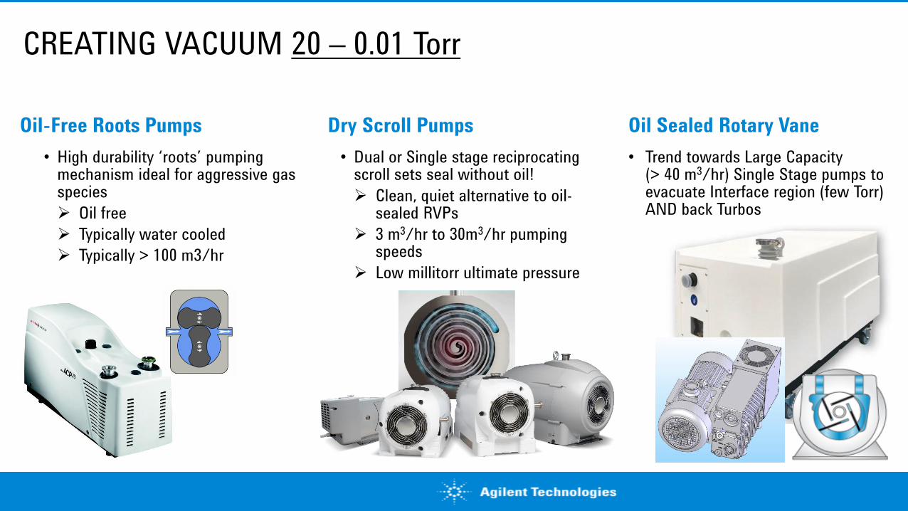
CREATING VACUUM 20 – 0.01 Torr
Dry Scroll Pumps
• Dual or Single stage reciprocating scroll sets seal without oil!
➢ Clean, quiet alternative to oil-sealed RVPs
➢ 3 m3/hr to 30m3/hr pumping speeds
➢ Low millitorr ultimate pressure
Oil-Free Roots Pumps
• High durability ‘roots’ pumping mechanism ideal for aggressive gas species
➢ Oil free
➢ Typically water cooled
➢ Typically > 100 m3/hr
Oil Sealed Rotary Vane
• Trend towards Large Capacity(> 40 m3/hr) Single Stage pumps to evacuate Interface region (few Torr) AND back Turbos

CREATING VACUUM 10-3 – 10-8 Torr
Vapor Jet (Diffusion) Pumps
• High velocity Oil Jet (vapor) from diff-stack strikes gas molecules:
➢ Oil mist condenses at (water) cooled body of the pump
➢ Cryo-cooled baffles at pump inlet can reduce oil mist from entering process chamber
Cryo-Pumps
• He recirculation system keeps large 1st stage array at 77K (water) & smaller 2nd stage array at < 15K (N2, Ar, CO, O2)
➢ H2, He, Ne pumped by charcoal on underside of 2nd stage
➢ 800 – 60K l/s pumping speed
➢ 10-3 – 10-10 Torr pressure
➢ Requires periodic ‘regeneration’
Turbo-molecular Pumps
• High speed (35K+ rpm) blades strike gas molecules directing them towards pump base
➢ Molecular Drag stage (ie. TwisTorr stage, shown) compresses gas 104 x & create torturous path for light gases
➢ Mechanical, hybrid, or mag-lev bearings

Turbo-Molecular Pump: Blade Section
• How it Works:
• Large INLET coupled directly to chamber allows highest probability of a particle entering the pump
• BLADES transfer momentum to particles; STATORS have complementary angle to reflect the particle
• Blade/Stator ANGLE decreases to prevent back-migration

Turbo-Molecular Pump: Macro-Torr Drag Stage
After particles exit the lowest blade stage (approx. 10-3 Torr) Spinning Disc transfers momentum
to them during residence time on the disc
V
Moving Wall with Speed V Imparts Forward Momentum

Turbo-Molecular Pump: Molecular Drag Stage
• How it Works:
• Molecular Drag Stage transfers momentum to particles during residence time on a rotating element and
directs the motion in a confined channel
- Rotating blade design can only compress gas to ≈ 10-3 Torr (max) & has poor pumping for light gases
Disk Rotor
Impeller
Channel
Stripper
Surface
MacroTorr (‘Gaede’)
Drum Rotor
Impeller
Helical Groove
Channel
HolweckTwisTorr (‘Siegbahn’)

Turbo-Molecular Pump: Molecular Drag Stage
• How it Works:
• TwisTorr® - Agilent’s most advanced Turbo-Drag Stage! The MacroTorr’s ‘stripper surface’ is
replaced with stators featuring complex channels to guide and compress gas molecules through
centripetal and centrifugal motion.

Turbo-Molecular Pump: Rotor Suspension
Mechanical Bearing Turbos:
- Ceramic Balls in SS housing
- Grease or Oil-lubricated
- Pre-load, alignment and shock resistance are keys
- Some designs use 1x Mechanical Bearing and 1x Permanent Magnetic Bearing
(‘Hybrid’ suspension)
Magnetic Levitation Turbos:
- 4 Separate magnetic bearings support and position
the ‘floating’ rotor
- ‘Safety’ or ‘Touch-down’ bearings support rotor
during ramp-up and shut-down
- Reduced electronics & computing cost help!
May 16, 201814

Getting to near-UHV Pressures (Time-of-Flight Section)
Consider the shape of the pumpdown curve Consider ALL potential gas sources
SD
Permeation (He, H2)
Outgassing (H2O, Solvents)
Backstreaming
(Oil, He)
Internal
LeaksReal
Leaks
Virtual
Leaks
Diffusion (H2)
Surface Conditions&
Trapped Volumes:Materials:Leaks:
Real
LeaksBack-
streaming
Diffusion
Virtual
Leaks
PermeationProcess
Desorption
Permeation
Time
Diffusion
Desorption
Pressure Decay
Pre
ss
ure
(To
rr)
10+3
10-0
10-6
10-9
10-3
Chamber Free Volume

Challenges in Reaching HV and near-UHV Pressures
Outgassing & Diffusion
• TEMPERATURE is the single most effective way to increase the outgassing and diffusion rates of components inside the vacuum chamber, allowing our HV pumps to remove the gas (mostly water)
➢ Heating (and Cooling!) must be done uniformly
➢ Effectiveness is proportional to Time (linear) and Temperature (exponential!)
➢ Getting the heat to internal partsa challenge!
Material Selection
• “If you don’t want to pump it out, Don’t put it in!”
• Choose materials based on the following criteria:
Permeation Rates
Bake-Out Temperature
Outgassing Rates
Chemical Compatibility
Mechanical Properties
Electrical Properties
• CERN ‘Recipe’ for cleaning parts for UHV:
https://pdfs.semanticscholar.org/fae5/6ae03f7c841f7aae5462a2631bbbbeed529f.pdf

Vacuum System Troubleshooting
Pumpdown Curve
• Slope (p/t) can help determine if vacuum leak is ‘Real’(outside-in) or ‘Virtual’ (outgassing or desorption)
• System with ‘consistent’ shaped pumpdown curve but decreasing performance may indicate pump problem
Leak-Up Rate
• Slope (p/t can help determine if vacuum leak is ‘Real’(outside-in) or ‘Virtual’ (outgassing or desorption)
110-7
10-6
10-5
10-4
Pre
ssure
(T
orr
)
10 100 1000Time (min)
As system is used,pumpdown timebecomes longer
TimePressure
(System A)
Rate of
Rise
Pressure
(System B)
Rate of
Rise0 5.00E-04 5.00E-04
5 5.00E-03 5.00E-03
10 7.00E-03 Virtual 7.00E-03 Real
15 9.10E-03 0.42 8.00E-03 0.20
20 1.10E-02 0.38 9.00E-03 0.20
25 1.26E-02 0.32 1.00E-02 0.20
30 1.40E-02 0.28 1.15E-02 0.30
35 1.52E-02 0.24 1.32E-02 0.34
40 1.65E-02 0.26 1.45E-02 0.26
45 1.77E-02 0.24 1.60E-02 0.30
50 1.87E-02 0.20 1.70E-02 0.20
55 1.98E-02 0.22 1.78E-02 0.16
60 2.07E-02 0.18 1.90E-02 0.24
65 2.16E-02 0.18 1.98E-02 0.16
70 2.22E-02 0.12 2.06E-02 0.16
75 2.26E-02 0.08 2.16E-02 0.20
80 2.29E-02 0.06 2.25E-02 0.18
85 2.31E-02 0.04 2.40E-02 0.30
90 2.32E-02 0.02 2.55E-02 0.30

Helium Leak Detector
Spray Helium Application
Large Vacuum Chambers:
➢ HLD Connected to SUT (system under test) between High Vacuum and Rough Vacuum Pumps
‘Small’ Vacuum Chambers
➢ HLD connected directly to chamber: Leak Detection is a Rough Vacuum (Viscous Flow) process
Sniffing ApplicationComponent or Vacuum System PRESSURIZED with He:
➢ HLD operated in ‘Sniffing’ mode to detect He escaping from the part or chamber
➢ ‘Bombing’ is a multi-step process where components are pressurized then sniffed

Simple Magnetic Sector Mass Spec Vacuum System
SD
1-3 m3/hr
50-300 l/sec
Turbo
Pump
2-Stage
RVP
System Design Features• Turbo Molecular Pump evacuates
Spectrometer tube to 10-5 Torr Pressures
• Contra-Flow Design makes use of Turbo Pump’s (relatively) poor He compression
• Dual Stage RVP or Scroll improves Foreline compression (prevent He backflow)
• Single Stage Scroll can be backed by small Diaphragm Pump to achieve same result

Double Focusing Magnetic Sector Mass Spec Vac System
System Design Features• Large Capacity Turbo or Dual Stage
Primary Pump required to reduce inlet gas
load
• Dedicated Backing Pump for Mag Sector
Section maximizes compression
• System layout complicates move to Multi-
Inlet Turbo Pumps
Trends
• Movement to Oil-Free Scroll pumps vs RVPs (contamination)
Turbo Pump

GC Quadrupole or Ion Trap Mass Spec Vac System Design
QUADRUPOLE MASS FILTER
• RF (& DC) Voltages set so target mass ion have stable motion in the quadrupole
• Ions of larger (or smaller) mass have unstable motion and are ejected
SD
Detector
GC Inlet
Single or Dual
Stage RVP
_10-5 Torr
Turbo-Drag
OR
Vapor Jet (Diffusion)
Pump
1-3 m3/hr
50-300 l/sec
ION TRAP MASS FILTER
• In Trapping Mode, Ions coalesce towards the center of the trap
• Ramping voltages selectively ejects Mass Species from the trap
System Design Features• Single inlet Turbo Pump (typ. With Drag
Stage) backed by Oil-Sealed RVP or Multi-
Stage Diaphragm Pump
Trends
• Movement to Oil-Free Scroll pumps vs RVPs (contamination) or Diaphragm Pumps (maintenance)
• Fewer Diffusion Pump systems produced
• Improved Vacuum Sub-System Cost & Reliability

Traditional Quadrupole LC-MS Vac System Design
SD SD
_ 10-5 Torr_10-3 Torr
1 – 3 Torr
< 5 x 10⁻² Torr
50-300 l/sec
50-800 l/sec
10-28 m3/hr
10-16 m3/hr
System Design Features
• Dedicated, Dual Stage RVPs required to ‘back’ non-compound Turbo Pumps
• 28 m3/hr RVP on Interface: The Speed of Light for Single f Power
• Large Gas Load in 10-3 Torr (Transition Flow) region required large pump inlet sizes
• Vacuum Sub-System Cost
• Vacuum Sub-System Reliability➢ Ceramic Ball Bearing Turbos➢ Optimized Cooling Systems

Modern Quadrupole LC-MS Vac System Design
SD SD
_ 10-5 Torr_10-3 Torr
System Design Features
• Drag Stage Turbos eliminate need for dedicated dual-stage RVPs
• Inverter Driven RVPs obliterate 28 m3/hr limit on Interface/Backing Pump Size
• Large Gas Load in 10-3 Torr (Transition Flow) region require large pump inlets
• Large Single Stage RVPs reduce cost
Trends
• Larger size (or multiple) Single Stage RVP backing Pumps (up to 120 m3/hr!)
• Some movement to Oil-Free Pumps16-40 m3/hr
50-300 l/sec
50-800 l/sec
1 – 3 Torr

Optimized Quadrupole LC Mass Spec Vacuum System Design
Detector_ 10-5 Torr
_10-3
Torr
1 – 3 Torr
System Design Features• Dual-Inlet Turbo Pump evacuates two
independent regions to different vacuum levels
➢ Pump custom designed to match customer gas loads
• Restricting 10-3 Torr Region inlet has SOME impact on pumping speed (Transition Flow)
• Vacuum Sub-System Cost (MS RVPs)
Trends• Insertable Pumps Optimize Conductance &
Reduce Cost
• Some movement to Oil-Free Pumps
180-400l/sec
150-300l/sec
16-40 m3/hr

Triple Inlet Turbo LC-MS Vacuum Sub System
_ 10-5 Torr
_10-3 Torr
1 – 3 Torr
System Design Features
• TRIPLE Inlet Turbo Pump has direct inlet to drag stage (0.1 – 0.5 Torr) – allowing higher inlet gas flows
Trends
• Insertable Pumps Optimize Conductance
• Some movement to Oil-Free Pumps

Quadrupole Time-of-Flight Vacuum Sub System Design
_ 10-5 Torr_ 10-3 Torr
_ 10-7 Torr
System Design Features
• Multi-Pass TOF designs replacing single- or dual-pass systems (reduces system size; complicates Turbo placement)
• Dedicated Turbo Pump for TOF Section
Trends
• Other vacuum regions used to ‘back’ TOF section Turbo (maximize compression/ negligible gas flow)
• Movement to Oil-Free Pumps
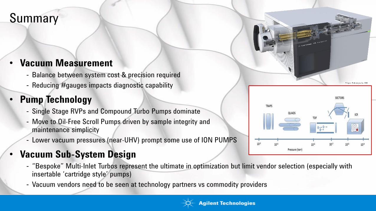
Summary
• Vacuum Measurement- Balance between system cost & precision required
- Reducing #gauges impacts diagnostic capability
• Pump Technology- Single Stage RVPs and Compound Turbo Pumps dominate
- Move to Oil-Free Scroll Pumps driven by sample integrity andmaintenance simplicity
- Lower vacuum pressures (near-UHV) prompt some use of ION PUMPS
• Vacuum Sub-System Design- “Bespoke” Multi-Inlet Turbos represent the ultimate in optimization but limit vendor selection (especially with
insertable ‘cartridge style’ pumps)
- Vacuum vendors need to be seen at technology partners vs commodity providers

Agilent Vacuum Education Programs
To learn about more Agilent Vacuum Technology Education programs, including:
- Basic Vacuum Practice and Introduction to Leak Detection classes- On-site Vacuum Technology Seminars- Custom multi-day classes at your site
…please contact Agilent Vacuum Customer Care (800-882-7426 – Option 3) or e-mail Robin Arons ([email protected]).
Click HERE to access Agilent’s excellent video series on Care and Use of Turbo Pumps.
Click HERE for more information on Helium Leak Detection, including details on Agilent’s new HLD instrument.