Embed Size (px)
Citation preview
-t6630 ICE-CORING AUGERS FOR SNALLON DEPTH API(UCOD v
REGIONS RESEARCH AND ENGINEERING LRB HANOVER M4RND ET AL. DEC 05 CRREL-85-21
FlE F/0G B/12 N
A I0:.mEE mmosm
pr
Ulml.
ko 12.0
1 25 111111.4
MICRnCOP' CHA4RT
DTIC"ZlUL L J.LECTE US Army Corps
REPORT 85-21 AP . of Engineers• . - APR 0 7 M
Cold Regions Research &Engineering Laboratory
I ID
APIOved for pubMec "
Ice-coring augers for shallow depth sampling
0:--'--
I"
CRREL Report 85-21 .
December 1985
* .. ,, o. - **%
Ice-coring augers for shallow depth sampling
John Rand and Malcolm Mellor
j %
.
Prepared for
OFFICE OF THE CHIEF OF ENGINEERS
* Approved for public release; distribution is unlimited._

Unclassif iedSECURITY CLASSIFICATION OF THIS PAGE r17'n Date Entered)
I READ INSTRUCTIONS%REPORT DOCUMAENTATION PAGE BEFR COPETN.FR
I REPORT NUMBER 2GOTACCESSONO.: RECIPIENT'S CATALOG NUMBER
CRREL Report 85-21 ____ ________
4. ToITL E (wnd Subtilel) -. TYPC OF REPORT A PERIOD COVERED
ICE-CORING AUES OSHALLOW DEPTH SAMPLING _____________
6 PERFORMING ORG. REPORT NLMSER
-. 7. AUTNOR(oJ B. CONTRACT OR GRANT NUMBERr.)
John Rand and Malcolm Mellor
*9. PERFORMING ORGANIZATION NAME AND ADDRESS 10. PROGRAM ELEMENT. PROJECT. TASKU.S. Army Cold Regions Research and AE OKUI UBR
*Engineering Laboratory DA Project 4A762730AT42Hanover, New Hampshire 03755-1290
I CONTROLLING OFFICE NAME AND ADDRESS 12. REPORT DATE
Off ice ofthe Chief of Engineers Deebr1985Washington, D.C. 20314-1000 13 NUMBER OF PAGES
_____________________________________________ 27*14 MONITORING AGENCY NAME d AODRESS(if different from Controlling Office) 15. SECURITY CLASS. (of thise report)
'1! or_-
Unclassif iedSo -a %a a
I~.DECLASSIFICATION DOWNGRADINGSCHEDULE
16. DISTRIBUTION STATEMENT (of this. Report,)
* ~Approved for public release; distribution is unlimited. 2 '-
17. DISTRIBUTION STATEMENT (of the. abstract enitered In &lock 20, It different from, Report)
IS. SUPPLEMENTARY NOTES
19 KEY WORDS (Continue. on rev-ere# aidd* It necessary' and Identify by block rnmber)
Augers IceCold regions PermafrostCore sampling SoilsDrilling
* 2Q ASTR'ACT (CmW1=uo an r.erme *Edo If nwc..eary and Idlentify by block nugnber)* The development of lightweight coring augers for ice is reviewed. Emphasis is on equip-* ment designed by the Cold Regions Research and Engineering Laboratory and its prede-
cessor organizations for sampling to depths less than 20 m or so. Design and operation* of the ACFEL/SIPRE/CRREL 3-in.-ID corer is discussed, and modifications of the basic -
design for powered operation and for drilling in frozen soil are outlined. Recent replace-* . ments for the traditional coring auger are described, and details are given for the construc
tion and operation of the new 4 1-in-ID coring equipment. A powered 12-in.-ID drill for* shallow-depth coring is also described. -
DOhA 13 03 EDITION OF V NOW 6 S OBSOLETEDDI*n7 UnclassifiedSECURITY CLASSIFICATION OF THIS PA-,E 'Whe Dot- FrWr - -we
€. . . . . . . . . . . . -%-. .-
PREFACE
This report was prepared by John Rand, Research General Engineer, Ice Engineering Re-search Branch, and Dr. Malcolm Mellor, Research Physical Scientist, Experimental Engi-neering Division, U.S. Army Cold Regions Research and Engineering Laboratory. The re-port was produced under DA Project 4A762730AT42, Design, Construction, and Opera-tions Technology for Cold Regions._ ,"' ".
The authors are grateful to Paul V. Sellmann and Herbert Ueda for their help in preparing 1
and reviewing this report. " "The contents of this report are not to be used for advertising or promotional purposes. Ci-
tation of brand names does not constitute an official endorsement or approval of the use ofsuch commercial products.
-°p -
. *,-. .. . . . .- . . ,
*.. . . . -
o-.,w .
96' .. ,
., °\'.,. % ,
. 0
CONTENTS
PageA bstract ................................................................ iP reface ................................................................. iiIntroduction ............................................................. IThe 3-inch ice corer ....................................................... 2 " 'The Rand auger ........................................................ 7 . "Parallel development of comparable drills .................................... 13The Big John 12-inch corer ................................................. 16P ow er drives ............................................................. 20A simple Russian ice-corer ................................................. 21C onclusions ............................................................. 2 1Literature cited. ................................................... 22
ILLUSTRATIONS
Figure1. The original ACFEL ice coring auger .................................... 1 .
2. The 1-m-long core barrel of the SIPRE/CRREL 3-inch ice auger ............. 23. Cutters for SIPRE/CRREL 3-inch auger ................................. 34. Cutting shoe for SIPRE/CRREL auger .................................. 35. Core being removed from the upper end of the core barrel of the 3-inch auger.. 46. Driving head on the 3-inch SIPRE/CRREL auger ........................ 47. 3-inch C RREL auger .................................................. 58. SIPRE/CRREL 3-inch auger kit ........................................ 59. 3-inch CRREL auger with post-hole digger ............................... 6
10. Deep coring with the aid of a light tripod for lifting and lowering............. 611. First version of the 4 A-inch Rand auger............................... 712. Current version of the Rand auger ................................... 8 .-
13. Core barrel assembly and details of cutting head for current version of Randa uger .............. ........................................... 9
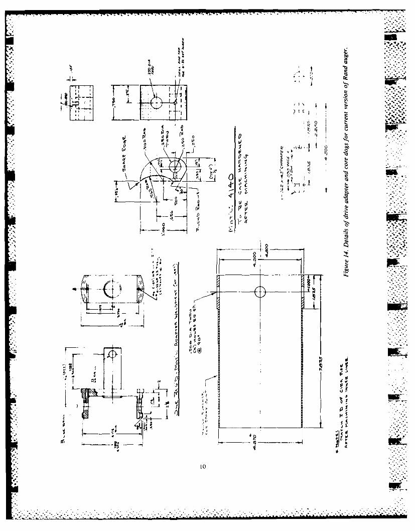
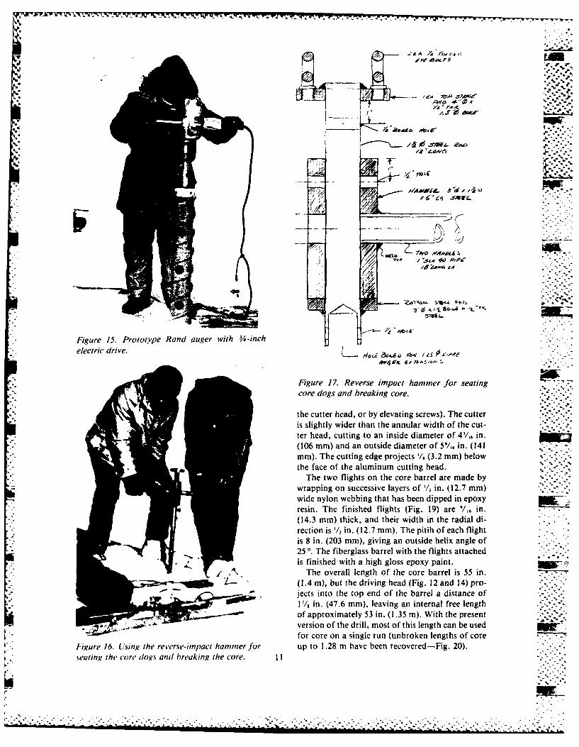
14. Details of drive adapter and core dogs for current version of Rand auger ....... 1015. Prototype Rand auger with 3/4-inch electric drive .......................... 1116. Reverse-impact hammer for seating core dogs and breaking core ............. I I17. Reverse impact hammer for seating core dogs and breaking core ............. 1118. Rand drill with section of flight auger for stirring cuttings above the core barrel 1219. Core barrel of Rand auger .............................................1220. Core of multi-year sea ice produced by the prototype Rand auger ............ 13 . .
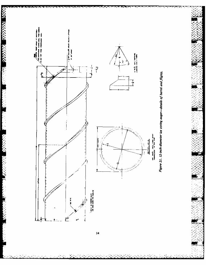
21. 12-inch-diameter ice coring auger-details of barrel and flights .............. 14 r.. .'."-."
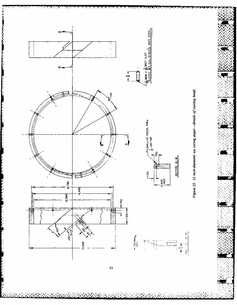
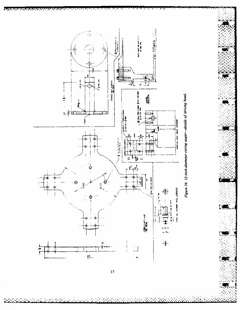
22. 12-inch-diameter ice coring auger-details of cutting head .................. 15 ,,23. Cutting head of 12-inch auger .......................................... 1624. 12-inch-diameter coring auger-details of driving head .................... 1725. 12-inch corer and core retrieval cylinder .................................. 1826. 12-inch core of multi-year sea ice ........................................ 1827. Two-prong gripper for lifting 12-inch ice cores .......................... 1928. Three-prong variant of gripper for lifting large-diameter ice cores............ 1929. Small drill rig used to operate the 12-inch coring auger .................... 20,30. Drill rotation speeds for power-driven ice coring augers .................... 20
31. Ice-fisherman's auger used for shallow coring in the U.S.S.R ................ 21
odesiii '- '. ." .
Di.t
Q ''I L' I
................ .. - I
John~~ Ran and Malol...lo
..af. "i
-a,
John Rand and Malcolm Mellor-" -
INTRODUCTION the Cold Regions Research and Engineering Lab-oratory (CRREL), a few minor changes were
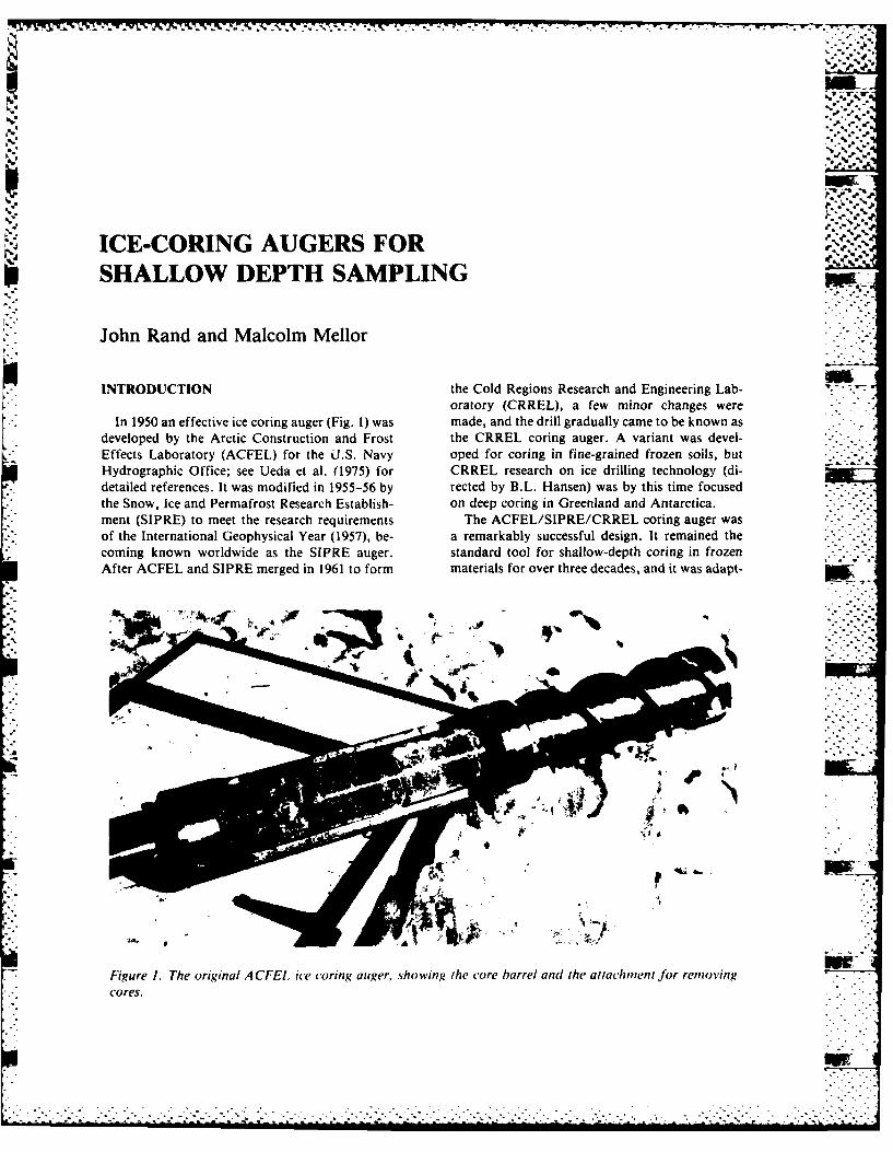
In 1950 an effective ice coring auger (Fig. 1) was made, and the drill gradually came to be known asdeveloped by the Arctic Construction and Frost the CRREL coring auger. A variant was devel-Effects Laboratory (ACFEL) for the J.S. Navy oped for coring in fine-grained frozen soils, butHydrographic Office; see Ueda et al. (1975) for CRREL research on ice drilling technology (di-detailed references. It was modified in 1955-56 by rected by B.L. Hansen) was by this time focusedthe Snow, Ice and Permafrost Research Establish- on deep coring in Greenland and Antarctica.ment (SIPRE) to meet the research requirements The ACFEL/SIPRE/CRREL coring auger wasof the International Geophysical Year (1957), be- a remarkably successful design. It remained thecoming known worldwide as the SIPRE auger. standard tool for shallow-depth coring in frozen . -. .- -.
After ACFEL and SIPRE merged in 1961 to form materials for over three decades, and it was adapt-
Figure 1. The original ACFEL ice coring auger, shoing the ore barrel and the attachment for removingcores.
• .. .........................................................................-. ."- ......... l.....". .. i-
""i/.. i...
K~~7~7JW7UW -.- A''. . - -
N ed for tasks well outside the original design limits. Bay and put to immediate operational use in sam-
Although designed primarily as a hand-held tool, piing multi-year pressure ridges in the Beaufortwith hand rotation, it later became a powered au- Sea. Apart from some minor problems with theger, driven by a hand-held electric drill or by a core-catcher device and with accumulation of cut- r
light gasoline unit of some kind. In some cases, it tings above the core barrel, the drills consistentlywas used on small drill rigs. For one-man opera- produced cores of unprecedented quality, fre- .' -' -
tion, a practical depth limit of about 6 m (20 ft) quently in unbroken lengths of 1 m or more. Thewas set, largely by the weight of the auger and the new drills were easy to handle and use, and weredrill rods, but hand-drilling by strong teams went much less prone to jamming than theolder CRRELas deep as 55 m (180 ft) in Greenland (Ragle et al. auger.1964). On the negative side, it was easy for inex- Over the past 4 years a number of small modifi-perienced or inept operators to overdrive the drill cations have been made, and the drill is now be-and jam it in the hole, especially in wet conditions lieved to be a superior replacement for the CRREL(sea ice, "warm ice," or partially thawed soils), 3-inch auger.and/or with high penetration rates (when produc- The following notes describe the original 3-inchtion of cuttings outpaces transport or exceeds stor- auger, the newer Rand drill, and other tools forage capacity). Intrusion of cuttings between the shallow-depth ice coring.core and the barrel could twist off the core period-ically, and long pieces of unbroken core wererecovered only rarely. The core barrel was also THE 3-INCH ICE CORERquite heavy.
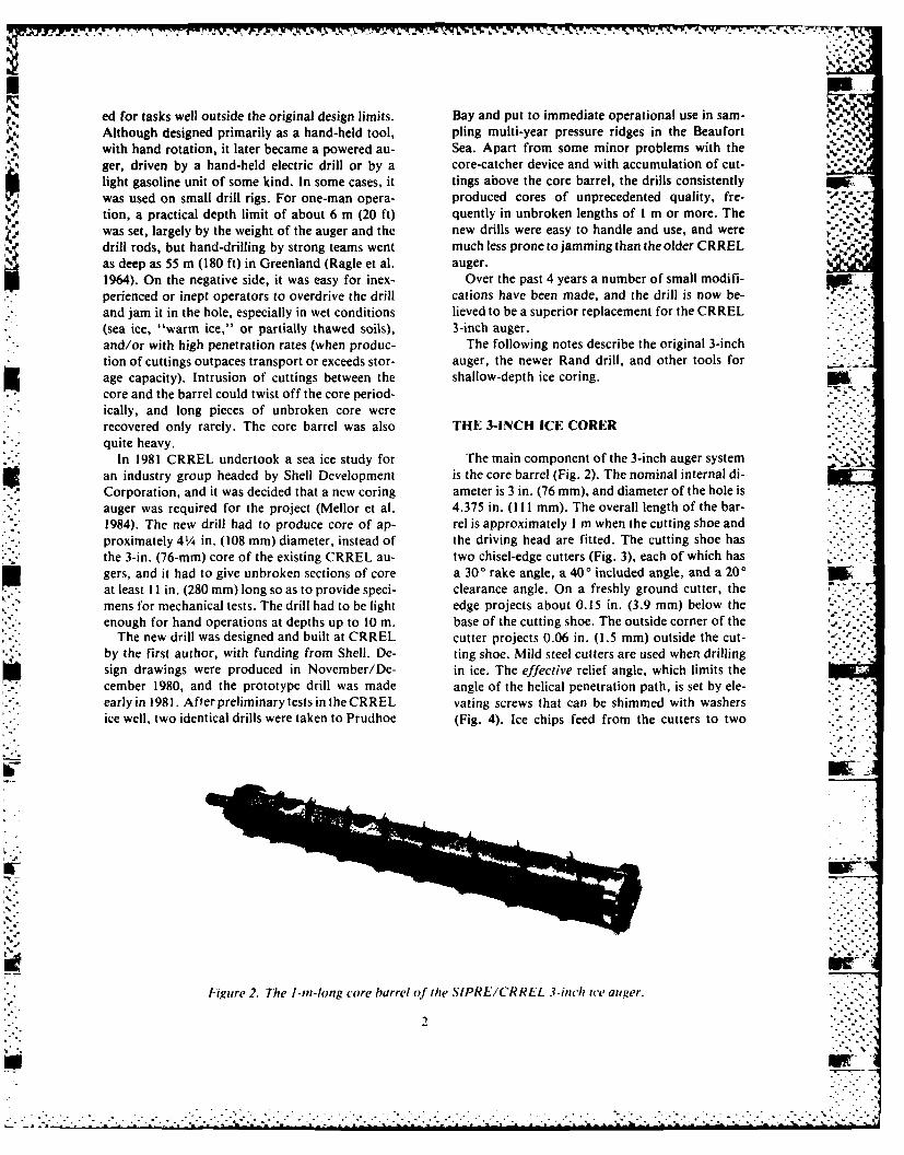
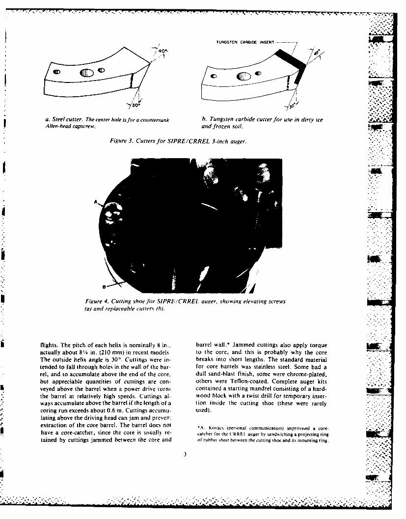
In 1981 CRREL undertook a sea ice study for The main component of the 3-inch auger systeman industry group headed by Shell Development is the core barrel (Fig. 2). The nominal internal di-Corporation, and it was decided that a new coring ameter is 3 in. (76 mm), and diameter of the hole isauger was required for the project (Mellor et al. 4.375 in. (111 mm). The overall length of the bar-1984). The new drill had to produce core of ap- rel is approximately I m when the cutting shoe andproximately 41/4 in. (108 mm) diameter, instead of the driving head are fitted. The cutting shoe hasthe 3-in. (76-mm) core of the existing CRREL au- two chisel-edge cutters (Fig. 3), each of which hasgers, and it had to give unbroken sections of core a 300 rake angle, a 400 included angle, and a 200at least II in. (280 mm) long so as to provide speci- clearance angle. On a freshly ground cutter, themens for mechanical tests. The drill had to be light edge projects about 0.15 in. (3.9 mm) below theenough for hand operations at depths up to 10 m. base of the cutting shoe. The outside corner of the
The new drill was designed and built at CRREL cutter projects 0.06 in. (1.5 mm) outside the cut-by the first author, with funding from Shell. De- ting shoe. Mild steel cutters are used when drillingsign drawings were produced in November/De- in ice. The effective relief angle, which limits thecember 1980, and the prototype drill was made angle of the helical penetration path, is set by ele- ,-...
early in 1981. After preliminary tests in the CRREL vating screws that can be shimmed with washersice well, two identical drills were taken to Prudhoe (Fig. 4). Ice chips feed from the cutters to two
.. .
Figure 2. The I-in-long core barrel of the SIPRE/CRREL 3-inch ice auger.
2
2 "*'%-
TUNGSTEN CAIDE INSERT-------
30*
a. Steel cutter. The center hole is for a countersunk b. Tungsten carbide cutter for use in dirty iceAllen-head capscrew. and frozen soil.
Figure 3. Cutters for SIPRE/CRREL 3-inch auger
/ .'A- -
Figure 4. Cutting shoe for SIPRE/CRREL auger, showing elevating screws(a) and replaceable cutters (b).
flights. The pitch of each helix is nominally 8 in., barrel wall.* Jammed cuttings also apply torque -
actually about 81/4 in. (210 mm) in recent models. to the core, and this is probably why the coreThe outside helix angle is 30'. Cuttings were in- breaks into short lengths. The standard materialtended to fall through holes in the wall of the bar- for core barrels was stainless steel. Some had a " " "rel, and to accumulate above the end of the core, dull sand-blast finish, some were chrome-plated,but appreciable quantities of cuttings are con- others were Teflon-coated. Complete auger kitsveyed above the barrel when a power drive turns contained a starting mandrel consisting of a hard- low,the barrel at relatively high speeds. Cuttings al- wood block with a twist drill for temporary inser-ways accumulate above the barrel if the length of a tion inside the cutting shoe (these were rarelycoring run exceeds about 0.6 m. Cuttings accumu- used).lating above the driving head can jam and prevern"extraction of the core barrel. The barrel does not *A. Kovacs (personal communication) improvised a core-''.- -.
have a core-catcher, since the core is usually re- catcher for the .RREL. auger by sandwiching a projecting ring
tained by cuttings jammed between the core and of rubber sheet between the cutting shoe and its mounting ring.
3
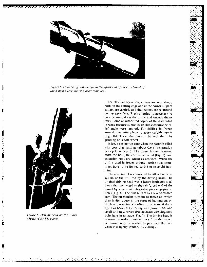
Figure 5. Core being reinoved fromn the upper end of the core barrel ofthe 3-inch auger ('driving head remnoved)i.
For efficient operation, cutters are kept sharp,both on the cutting edge and at the corners. Sparecutters are carried, and dull cutters are re-groundon the rake face. Precise setting is necessary toprovide overcut on the inside and outside diam-eters. Some unauthorized copies of the drill failedto work because subtleties of side-clearance or re-lief angle were ignored. For drilling in frozenground, the cutters have tungsten carbide inserts IS(Fig. 3b). These also have to be kept sharp bygrinding on a soft wheel.
In ice, a coring run ends when the barrel is filledwith core plus cuttings (about 0.6 m penetrationper cycle at depth). The barrel is then removedfrom the hole, the core is extracted (Fig. 5), andextension rods are added as required. When thedrill is used in frozen ground, coring runs some-times have to be limited to 0.3 m to avoid jam-ming.
The core barrel is connected to either the drivesystem or the drill rod by the driving head. Theoriginal driving head was a heavy laminated steel Mblock that connected to the reinforced end of thebarrel by means of retractable pins engaging inholes (Fig. 6). The pins retract by a lever-actuatedcam. The mechanism is prone to freeze-up, which
r then invites abuse in the form of hammering onthe lever, sometimes leading to permanent dam-age. For heavy duty drilling with powerheads andsmall drill rigs, robust driving heads with dogs and
Figure 6. Driving head opt ft, 3-jnch bolts have been made (Fig. 7). The driving head isSIPRECRREL uu-er. removed in order to extract core from the barrel. -
A ramrod may be needed to push out the corewhen it is tightly jammed by cuttings.
4
fJf
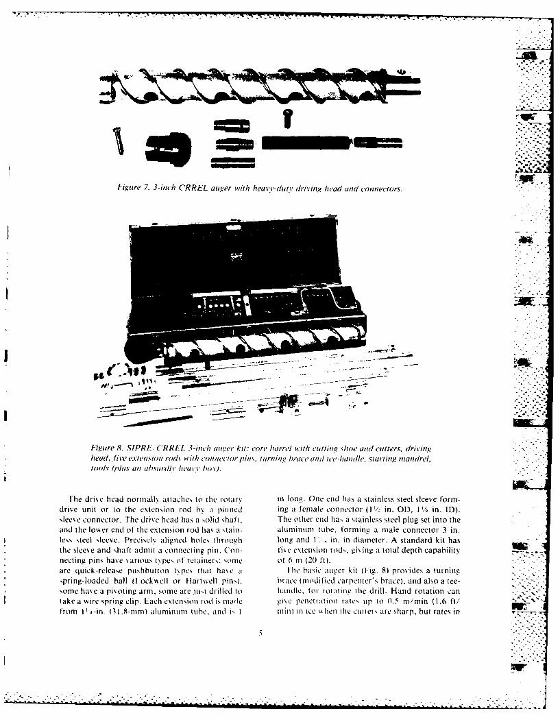
Figure 7. 3-inch CRREL auger with heavY-dutY dIriviny head and connectors.
igure 8. SIPRI:. ('RRL'L 3-,ih age A r or /e wth Isit ingshoe and cutters , drivinghead, five extensiton r(Jd% ithl connect1or pin's. turnin brace and w'e-hanrdle. starting mandrel,toolsv (plus an ah.surollv heavy box).
The drive head normally attaches to the rotarv m long. One end has a stainless steel sleeve form-drive unit or to the extension rod by at pinned ing a femiale connector (I I, in. OD, 11 4 in. ID).sleeve connector. The driveha a sldsat The other end has a stainless steel plug set into theand the lowecr end of the extension rod has a stain- aluminum tube, forming a male connector 3 in.less steel sleeve. PrecisclN aligned holes, through longL and I .. in. in diameter. A standard kit hasthe sleeve and shaft admit a connecting pinl. (ion- f'ive extension rods, gis ng a total depth capabilitynecting pins hav e various types of retainers: Some1 of 6 in (2(0 ft).are quick-release pushbutton types that have a I-li basic augver kit (11g;. 8) provides a turningspring-loaded ball (lockskell or Hartsell pins), brace (mo1dified carpenter's brace), and also a tee-
* some has e a pivoting arm, some are just drilled to handle. for rotating the drill. Hand rotation can -
take a w~ire spring clip. Each extension rod is made gis e penetration rates uip to 0.5 ni/mmn (1.6 ft/from V' 4 -in. (31 .8-mm) alurminunm tube, and is I rinii in ice lhen tilie cutters are sharp, but rates in
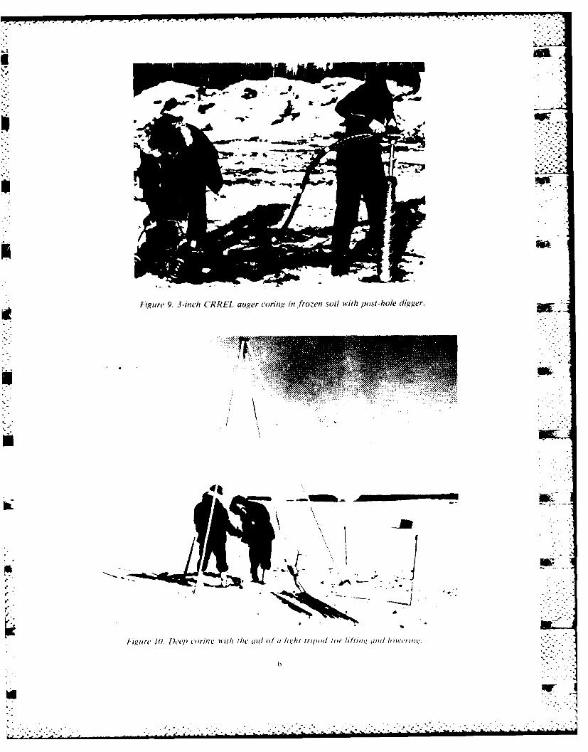
Figure 9. 3-inc/i CRREL auger coring in frozen soil wvith post-hole digger.
Bici
i7
Iuiiirc' 10. PI'(7) ennui.n' wIth the aid of a h k! h trimod 1un Pi hlim i and h Iv ~'Ill L:
I~ . . . . . . . . ... . . . .
the range 0.15 to 0.35 m/min (0.5 to 1.1 ft/min) When penetration depth exceeds 6 m (20 ft),are more typical, two or three people are needed to raise and lower
The auger can also be rotated by a 3/4 -in, electric the drill and to hold the string while adding or re-drill turning at about 300 to 500 rev/min. The re- moving extension rods. A split collet at the mouthquired adapter has a female end compatible with of the hole is useful for supporting the weight ofthe extension rods or the core barrel head, and a the string, and a tripod or gin pole helps in raising -*
solid shaft that can be gripped in the chuck of the or lowering (Fig. 10).drill. With electric drive, penetration rates in therange 0.75 to 1.7 m/min (2.5 to 5.5 ft/min) havebeen achieved (Kovacs 1970, Kovacs et al. 1973, THE RAND AUGERMellor et al. 1973).
Hand-held gasoline engines can be used to drive Auger specifications for the 1981 CRREL/Shellthe drill. Suitable units are power heads for small project called for a core diameter in excess of 4 in.post-hole diggers or for ice-fishing augers. These (102 mm) in order to permit precise machining ofare geared down to give about 200 to 500 rev/min. the ice down to 4 in. diameter (Mellor et al. 1984).
With gasoline drive, penetration rates around I Unbroken core was required in lengths to exceedm/min (3.3 ft/min) have been measured. II in. (280 mm), and relatively long coring runs -
Another type of gasoline drive has been used, were considered necessary (I m of coring penetra-especially for coring in frozen ground. This is a tion per cycle). When these requirements are met,post-hole digger in which the engine is mounted on the weight of core lifted each cycle becomes morea wheeled dolly and connected to the rotary drive than three times the weight of core lifted by the
unit by a flexible cable (Fig. 9). In ice-rich frozen 3-inch auger, so the weight of the drill itself had to
silt, this type of arrangement has given penetra- be minimized to permit hand operation by two - -
tion rates up to 3.7 m/min (12 ft/min) with ag- people. Z --
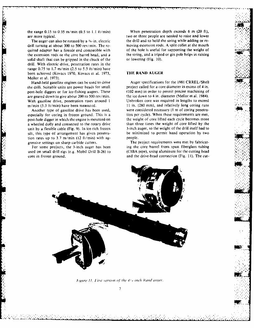
gressive settings on sharp carbide cutters. The project requirements were met by fabricat-For some projects, the 3-inch auger has been ing the core barrel from spun fiberglass tubing
used on small drill rigs (e.g. Mobil Drill B-26) to (CIBA pipe), using aluminum for the cutting head
core in frozen ground. and the drive-head connection (Fig. 11). The cut- -' -"'-"It t
figure II. First versiofn Of the(, 4 '-inc Rand au,.ger.
7
. .... -7 = • ,-.
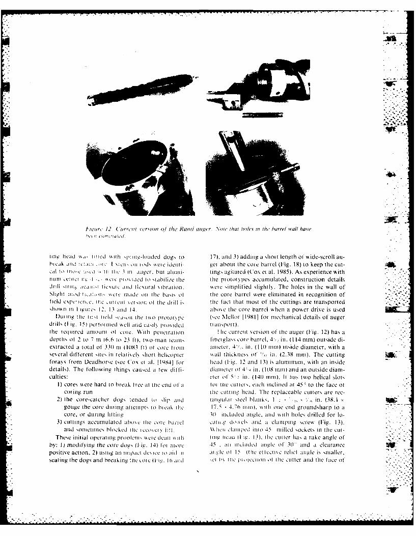
i curt, 12- ( uriit version 0./ Mei Rand uler. Note' that holes mn dhe barrel wall have
t1ine head %%,'t, ied %. oh 'pring-loaded dogs to 17), and 3) adding a short length of wide-scroll au-break Mid rL1h1 W'i I 01 st ds %%ere idctiti- gcr about thle core barrel (Fig. 18) to keep the cut-
cal 11o , I iol :. th tc 1 -Ill. Mvugr, but all umi1- tings agitated (Cox et al. 1985). As experience with1Ltiun eii icr 11C I. C1 eC Ili 0% lLdd t0 Stabilile thle thle prototypes accumulated, construction details . -
drill i rmiL ia: ii~ tics ut 11, atidIC\ljral s brat ion. a. crc simplified slightly. The holes in the wall of ..
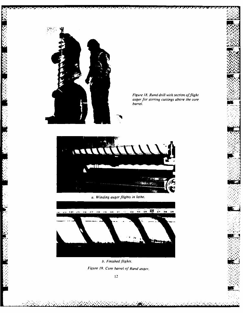
*Slabi niod iti-o,~ %%i a.c e Itad oil thle basis of the core barrel \,ere eliminated in recognition of'field espet ien~c. :tic uliv iii %ci ioti ot tilie drill " thle fact t hat most of the cuttings are transportedshosn ii i I igurc, 12. 1 3 tild 14. above tile core barrel \\bhetl a power drive is used
I)ut i~ til e t irst icId 'cCon111 til hc ao roi ot pe (,,ce Mellor 1 19811 for mechanical details of augerdrills, 0iig. I s) pcierot ited \%ell atid eaily pros ided ti atisport )
the req utred antouIt of core. WitlIi petici rat ion lhe current versioti of' the auger (Fig. 12) has adepths of 2 to -1 iil (6.6 to 23 ft ), tsso-tnri teatr' tibet glass corc barrel, 4 - in. (114 tmm) outside di-extracted a total of 330) in (1(083 ft)I of core t miii artcr. 4'/,, in. (lI1turnm) inside diameter, wNith aseveral different sites itt reilt l is ek hort helicopter ss all thickness of' in. (2.38 rum). The Cuttingforays from Deadhorse (see Cox ei al. [19841 for head (V ig. 12 atnd 13) is aluminum, with anl insidedetails). The following things caused al few di ffi - diattict cr o I 4 1,inl. (10)8 tutimI and anl outside diamn-culties: eter of 51 s in. (140) mmn). It has tsso helical slots
I) cores %Acere hard to break tree at tile end of at or tile cutlts, each iniclitned at 45' to thle face of'coring run tlie cuttitug head. The replaceable ctutters are ree-
2) the core-catcher dogs fetnded to slip ;ttid tatlar1,1 steel blatuks. I' in. (38.1 xgouge the core during auteitpt s to hi ca, tlie 17. 4.6 tmt), ss it i otne crd groundsharp to atcore, or durng littite 3)) iludedLI(. atigl. and Ns\t 1i holes drilled tfor lo-
3) cuttius accumlulated abose [tie Core ha,.ic! catine dosels aMid ai clatiliig screw (Fig. 13).and sotitucs blocked rte iccosers lilt. \\lien Cllijped tWO 45 tmilled sockets inl the cut-
*These initial operatitng pi rnletis,\ vsi c dcati %ko ih i tg tcad 0 ig. 13), tile cutter has a rake angle of'by: I) miodifyinug the core dogs 0 iL!. 14) toito cot 45 .ait ticlilded~ atlel of 301 atd at clearancepositiv e action, 2) uising atl i pi~act des ice t o aid i i anglec of Is (h tc cliuse relict aungle is smialler,seating the dogs arid breakingr tile cote (liw. 10 and cl t% 11ic pIi ltoul of thle cutter and thle face ot
I Ir
-. _ -I--- -.
"
J
• r A
I L4L
[.~~ jo i.: ., ,.
! -- - # - -
- -,;-- " ;-:.- A
-I T- I - ,. .... '.F,_ ,- ! 1 . ° -. - ..... '
- .~. .- I - .> - '4 ' . .
.
.,
. .
Li
-, ' - , " .6.-
- . ._ .. I A -.- - - T-- "=" ' . . ""
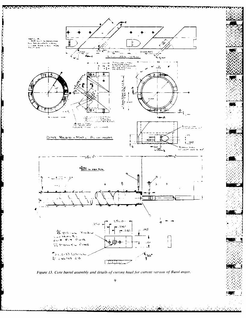
Figure 13. Core barrel assembly and d etails o.f cufting head .for current vers ion o Rund auger.
9
* 2 - ~ - *, .- ~4.:. - . - , %
to~
00
07 L. Ks
Its
-L -L- T9
all to) 00.r
EA /,.f jaw.
* - /E". -.17o'.
.,
S- 1A 17MI AA.
!,- ......
* ~ Figure 15. Prototype Rand auger with -inch~~~~~electric drive. o o /z w-
Figure 17. Reverse impact hammer for seating -~~~core dogs and breaking core.....
the cutter head, or by elevating screws). The cutter"--'-.~~~~is slightly wider than the annular width of the cut-..-.-'.
. ~ter head, cutting to an inside diameter of 4'/,, in.t:::: ~(106 mm) and an outside diameter of 5'/, in. (141."-."." • ~~mm). The cutting edge projects 1/, (3.2 mm) below .--.-"" ~~the face of the aluminum cutting head. ,:..-
. ~~~The two flights on the core barrel are made by %.....i . ~wrapping on successive layers of '/2 in. (12.7 mm) '.--u . Iwide nylon webbing that has been dipped in epoxy"-" resin. The finished flights (Fig. 19) are '/,6 in..
'" ~(14.3 mam) thick, and their width in the radial di-""""
"-" ~rection is /2 in. (12.7 mam). The pitih of each flight""-"":.. ~is 8 in. (203 mam), giving an outside helix angle of ....~~~~~~25 0. The fiberglass barrel with the flights attached,-,,.: '.(
• " ~is finished with a high gloss epoxy paint. 1-, Ii ," The overall length of the core barrel is 55 in.-...
:': "/--" (1.4 in), but the driving head (Fig. 12 and 14) pro-..-.. "".• 1 lp ,L~d ", jects into the top end of the barrel a distance of ."'-''.
I I ' ;P 1 U/, in. (47.6 mam), leaving an internal free length ... .,
of approximately 53 in. (1.35 in). With the present "."* 'version of the drill, most of this length can be used ffl .
" -- for core on a single run (unbroken lengths of core
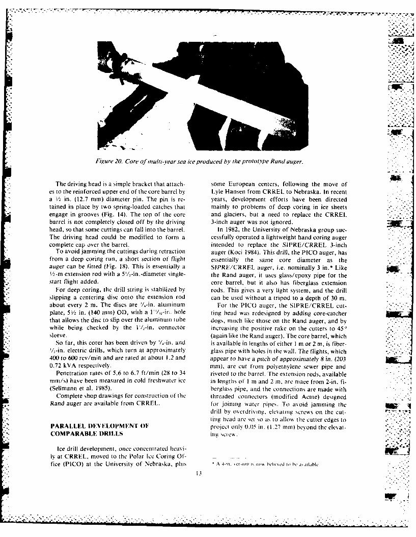
Figure 16. Using the reverse-impact hammer for up to 1.28 m have been recovered-Fig. 20).eating the ,'ore dlogs and breaking the core. 11 :::::-
/: -4"6
barrel
a.~~~~ ~ ~ ~ ~ Widn uefigt nlte
Fiur 18.she Radlrllwihsetinofs.h
Figure 19. Core barrelnau.
12I
.• - .', -
Figure 20. Core of miulti-.year sea ice produced by the protype Rand auger. >*The driving head is a simple bracket that attach- some European centers, following the move of
es to the reinforced upper end of the core barrel by Lyle Hansen from CRREL to Nebraska. In recenta !/. in. (12.7 mm) diameter pin. The pin is re- years, development efforts have been directedtamned in place by two spring-loaded catches that mainly to problems of deep coring in ice sheetsengage in grooves (Fig. 14). The top of the core and glaciers, but a need to replace the CRRELbarrel is not completely closed off by the driving 3-inch auger was not ignored.head, so that some cuttings can fall into the barrel. In 1982, the University of Nebraska group suc-The driving head could be modified to form a cessfully operated a lightweight hand coring augercomplete cap over the barrel, intended to replace the SIPRE/CRREL 3-inch
To avoid jamming the cuttings during retraction auger (Koci 1984). This drill, the PICO auger, hasfrom a deep coring run, a short section of flight essentially the same core diameter as theauger can be fitted (Fig. 18). This is essentially a SIPRE/CRREL auger, i.e. nominally 3 in.* Like/-in extension rod with a 5'/lz-in. -diameter single- the Rand auger, it uses glass/epoxy pipe for thestart flight added. core barrel, but it also has fiberglass extension
*For deep coring, the drill string is stabilized by rods. This gives a very light system, and the drillslipping a centering disc onto the extension rod can be used without a tripod to a depth of 30 mn.about every 2 in. The discs are 't.-in. aluminum For the PICO auger, the SIPRE/CRREL cut-plate, 5 V in. (140 mmn) OD, with a Il/,-i n. hole ting head was redesigned by adding core-catcherthat allows the disc to slip over the aluminum tube dogs, much like those on the Rand auger, and by
* while being checked by the V /,-in, connector increasing the positive rake on the cutters to 450sleeve. (again like the Rand auger). The core barrel, which
So far, this corer has been driven by Y/4 in. and is available in lengths of either I mn or 2 mn, is fiber-1/2-in. electric drills, which turn at approximately glass pipe with holes in the wall. The flights, which400 to 600 rev/min and are rated at about 1.2 and appear to have a pitch of approximately 8 in. (2030.72 kVA respectively. mmn), are cut from polyettiylene sewer pipe and
Penetration rates of 5.6 to 6.7 ft/mmn (28 to 34 riveted to the barrel. The extension rods, available*mm/s) have been measured in cold freshwater ice in lengths of' I mn and 2 i, are mace from 2-in. fi-
(Sellmann et al. 1985). berglass pipe. and the connections are made withComplete shop drawings for construction of the threaded connectors (modified Acme) designed
Rand auger are available from CRREL. fom- joining wNater pipes. To avoid jamming the __
drill by o) erdrivlng. elevating screws on the cut-ting head are set so as to alloss the cutter edges to
PARALLEL l)EVI.LOPMENTO project only 0.05S in. (1.27 mmn) beyond the ee-at-COMPARABLE D)RILLS i1112 sciew.
Ice drill development, once concentrated heavi- jp~ly at CRREL, moved to the Polar Ice Coring Of-fice (PICO) at the University of Nebraska, plus A 4-fi. kcrslor 1k Iko'A he e ti .1,1tblc.
13
.................................................--
...
.~ .~,..
-t ~ I..,
...
I9
.9. *--
S. p..
S. ~.1~ .' .'
* I .
9. 'p .1~4;' -.
-~* ~.v.U (I 1~-~ ~
* iJ __ K71~~*0
5.- mI~S..
be
I - - p.
N'
4I
be
<I, -.5
// 4"
4. 9- ~t U,
14
MW
a~lL
d%
ca 0
Lii
r4 r-J
_ _ _ _ _ _ _
Ln Olt
1-5
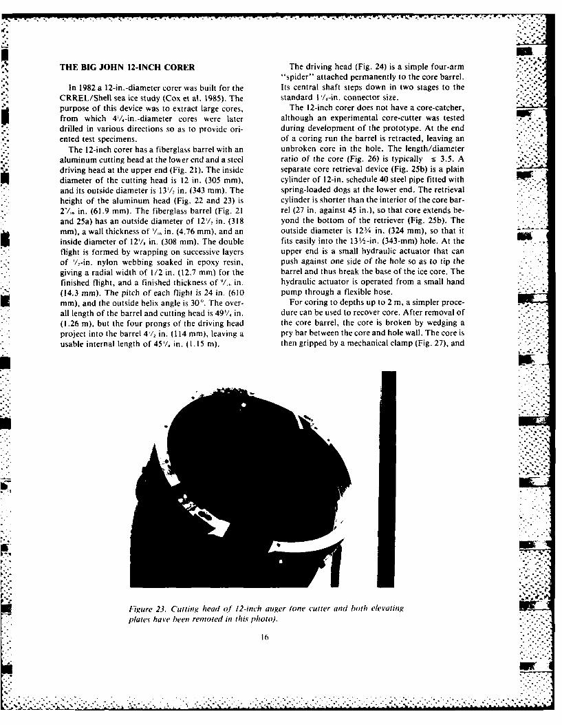
THE BIG JOHN 12-INCH CORER The driving head (Fig. 24) is a simple four-arm"spider" attached permanently to the core barrel.
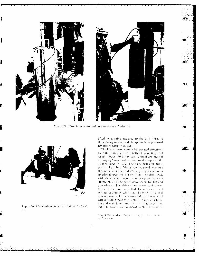
In 1982 a 12-in.-diameter corer was built for the Its central shaft steps down in two stages to theCRREL/Shell sea ice study (Cox et al. 1985). The standard l /,-in. connector size.purpose of this device was to extract large cores, The 12-inch corer does not have a core-catcher,from which 4/,-in.-diameter cores were later although an experimental core-cutter was testeddrilled in various directions so as to provide ori- during development of the prototype. At the endented test specimens, of a coring run the barrel is retracted, leaving an
The 12-inch corer has a fiberglass barrel with an unbroken core in the hole. The length/diameteraluminum cutting head at the lower end and a steel ratio of the core (Fig. 26) is typically :s 3.5. Adriving head at the upper end (Fig. 21). The inside separate core retrieval device (Fig. 25b) is a plaindiameter of the cutting head is 12 in. (305 mm), cylinder of 12-in. schedule 40 steel pipe fitted withand its outside diameter is 131/,, in. (343 mm). The spring-loaded dogs at the lower end. The retrievalheight of the aluminum head (Fig. 22 and 23) is cylinder is shorter than the interior of the core bar-27,, in. (61.9 mm). The fiberglass barrel (Fig. 21 rel (27 in. against 45 in.), so that core extends be-and 25a) has an outside diameter of 121/,, in. (318 yond the bottom of the retriever (Fig. 25b). Themm), a wall thickness of '!,, in. (4.76 mm), and an outside diameter is 123/ in. (324 mm), so that it - "
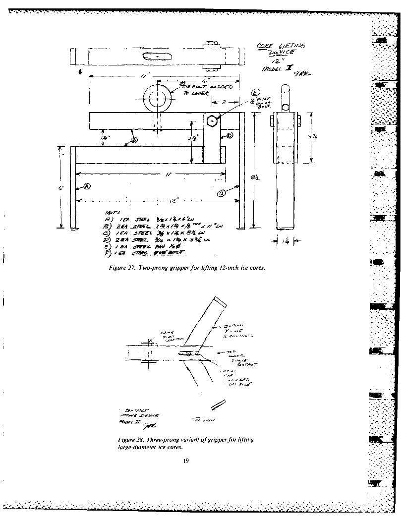
inside diameter of 12/, in. (308 mm). The double fits easily into the 132-in. (343-mm) hole. At theflight is formed by wrapping on successive layers upper end is a small hydraulic actuator that canof '/2-in. nylon webbing soaked in epoxy resin, push against one side of the hole so as to tip thegiving a radial width of 1/2 in. (12.7 mm) for the barrel and thus break the base of the ice core. Thefinished flight, and a finished thickness of /,. in. hydraulic actuator is operated from a small hand(14.3 mm). The pitch of each flight is 24 in. (610 pump through a flexible hose.mm), and the outside helix angle is 30'. The over- For coring to depths up to 2 m, a simpler proce-all length of the barrel and cutting head is 491/, in. dure can be used to recover core. After removal of(1.26 m), but the four prongs of the driving head the core barrel, the core is broken by wedging aproject into the barrel 4/ in. (114 mm), leaving a pry bar between the core and hole wall. The core isusable internal length of 45'/4 in. (1.15 m). then gripped by a mechanical clamp (Fig. 27), and
r S.
fgure 23. Cutting head of 12-inch auger (one cutter and hoth elevating M
plate have heen renoted in this photo).
16 ,6 ii!!!:iiw
A ... N
. 4,
/\ ~,,
-4~ ,J.
lb
u -b. -~
"4 .1~
U - 4.1 L *
4 ~L a.-
1
I N'
'-* ~
g2. -4.
I p ~ * -
-:N
-~ a..
-~+-- -4- s."* 4 ~ - ~
- <I;.41 ~ I
La.'V -- I/ I . -
- ~ ~zi'
- - + -- - ,-~',
- -b
I-
17
.IO
I m'ae 25. 12-inc ctorer (a) and core retrieval cl-limier (b).
lifted b\' a Cable attached to the dtil i't...three-pit~l miechianical clmp haN beeni propo'edfor futuire ork (F-ig, 28).
I I~he 12-inch corer Cannot be operatled effecti'k clb\ hantd, sinc i 1-1ttt2101 e1t of c W ie. 20)
wil\about 150 lb) (68 ku). \ 'il otecadrilling rig* \\a\ mnodified and u'edj to) opetic ate h
12-inich Corer itt 19S2. I hie basic: dilli uiti Ili~c,(the drill head b\ at - -hp air-cooledj eline~jjj etwi ti
1through at Npur veit r-Ceactionl L!i11 iti a uia 11iniitrotational \peecl of 14.4 ie\ iiii. I lie d11ll lme~il.
~ tt i~ attached etiii. t i \Cl 11) I ' 1ti 11id kI %1 ti
Simple tna'tt. tuiug roller dhJ li~ iii tot 101 atnddowi thruti fihe drik e ciait ii.itci uand do\ ni
0110rltforce are couttolicd h Ia \01livd.? through t a double reditetioti. Ilt Iic L' 0I 11ic b I
-- unit i" at trail. [o 01e-k t tie1. OWe J1111 "A' 111Led
\%d it a olditic: JMast Lelteiiioii. \ii11i hic~k' tot1 l lIinc, artd "tabili/ii. anid iii ott bi'ld ti 11!.-
I iurt 2f6. 12.imIidbouneter (-/vt ()1 multi- l ar e"' 29) fle trailer 11a1itdil ted '0 01i1 11 '011d be1
i C.
'Li/ cYD
"3ql P:f44V
L I E33I
Figure 27. Two-prong gripper for lifting 12-inch ice cores.
Y '
Figre28 Tre-prngvaiat fgrpprfr ifin
large-diametera icors
19 ..
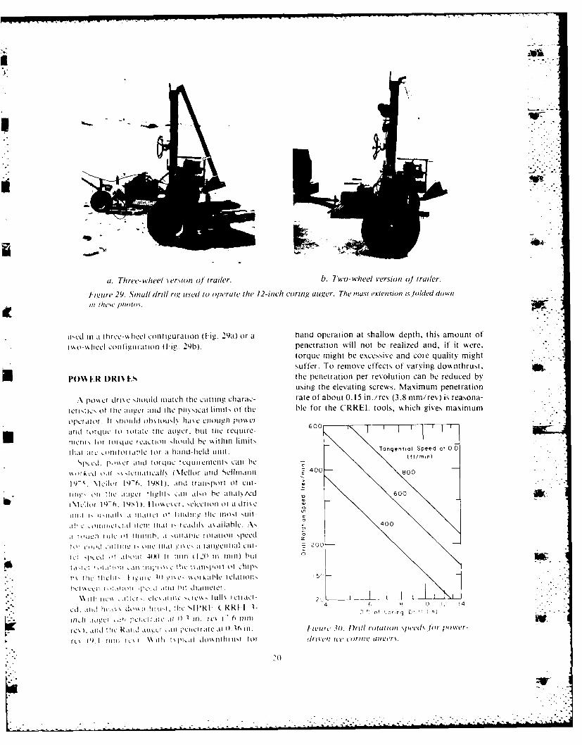
at. Three- wheel version of trailer. b. Two- wheel version 01 trailer.
1-igure 29. Small drill rig used to operate the 12-inch co~ring. auger. The mast exiension islolded down/In thew piorm.
o usd in a r liyee-%%hcel Configuration (1-ie. 29a) or a hand operation at shallow depth, this amount of'i o-N~theel conftigurat ion (F ig. 29b). penetration will not be realized and, if' it were,
torque might be excessive and core quality mightsuffer. To remove effects of' varying downthruSt,
UPO~k ER I)RI% Fj the penetration per revolution can be reduced byusing the elevating screws. Maximum penetration
*potme drse lhotirld march thle cutting charac- rate of about 0.15 in./rev (3.8 mm/rev) is reasona-
teristies of thle auiver aind (the phvxcal linmit,, of thle ble f'or the CRREI. tools, which gives maximum
oiprtlor It Snild ohs iouxl hds eeiOUgh p1Ox'erand torquec to rotate the augecr, but the require- 0113117
ttieiiv IoM torque reCiort01 1.htlld be wsithin limlitSthatl atc oIItttdPICn for a 11aud-heIl unit. agnilseda
'~~pee111 I0pU s~e n iqerqILiLi]riC~tlt', c.an bex%ot~v OH( ou \ Ieiitial Xllor aitd SCellntrarrn 400- 0
I \lcIlor 19-6, t981) Il ud liatr~port of cut-
-tuIig!, ),, ttic Iivcr tligtr c:at aso tie atiak/ed 60&
~\1ctoit~)I. 1q1 . Ilos% LS et. ,c~ctiion of a drie
W ill I l' i i Ix .u nat 1 t et 0? tiidtittv iI l lto~t -unt-
ihic ofltini ,iil iteit itat I, rcadil\ Isailhle. A" -40
arout.0i rule ot itiuttb. .i liliai'lc totatiolt Nreei 0
Im ""~ ',1110 , til ati IxeV d taiteetitilal k.i1t- 200
it ir 41H ( I t r111u i t-( I I .2 I i ti bitt
us tn~ I~tit' ilcic 11i c!IC- xxxikablc Ie~lottx
her~~~ 0-1 Hc 10 lxi i4dt~ itxiitee
0 0io 0-4 D.
: t c [ IJ I i a ' C V CL I L i e t I . t j ' .6 tw in
rex .,i tic Rktid aiIce iI pcai feeti iate 0 16 in,. letcx jN. IOrill rotation speeds loi, power-
rcx 1\1iiii cxi itIit -i 1i dxx itthitixNI tot (In, el ti Cotitii! auee~trs.
L:.0
drilling rates around 312 ft/min 1.1 m/min) with adrive unit rated at 300 rev/min (typical '/,-in. elec- ,-
tric drill).For a fixed (controlled) penetration rate, the Turning
chip clearing rate of the auger can be increased by Broce
increasing the rotational speed, but the chip sizethen decreases, giving greater tendency for adhe-sion by very small ice fragments. The speedsshosn in Figure 30 are adequate and safe with the ,
limits on penetration rate suggested above.For large diameter augers, the specifications for
po%%er drives need to be optimized in accordancewith the equipment available. Hand operation ofthe drilling function is perfectly feasible, but corescannot be lifted by hand. If a small drilling rig isused for both drilling and core recovery, it be-comes practical to apply more torque and power..*, Extension
Rod
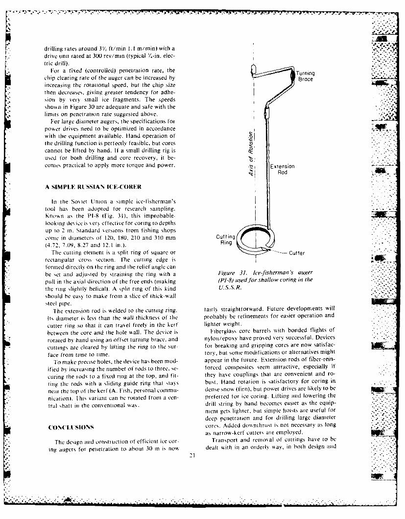
A SIMPLE RUSSIAN I(E-CORER
* In the Soviet Union a simple ice-fisherman'stool has been adopted for research sampling.Knon as the PI-8 (Fig. 31), this improbable-looking des icc is %xerN eftective for coring to depthstIp to 2 in. Standard ,ersions from fishing shops
conic in diameters of 120, 180, 210 and 310 mm Cutting
(4.72, 7.09, 8.27 and 12.1 in.). Ring
The cutting element is a split ring Of square or -- Cutterrectangular cross section. The cutting edge is 4formed directly on the ring and the relief angle can
be set and adjusted by straining the ring with a Figure 31. ice-fisherman's auger
pull in the axial direction of the free ends (making (PI-8) used for shallow coring in the
the ring slightly helical). A split ring of this kind U.S.S.R.should be easy to make from a slice of thick-wallsteel pipe.
The extension rod is "elded to the cutting ring. fairly straightforward. Future developments will
Its diameter is less than the wall thickness of the probably be refinements for easier operation and
cutter ring so that it can travel freely in the kerf lighter weight.
between the core and the hole wall. The device is Fiberglass core barrels with bonded flights of
rotated by hand using an offset turning brace, and nylon/epoxy have proved very successful. Devices
cuttings are cleared by lifting the ring to the sur- for breaking and gripping cores are now satisfac-
face from time to time. tory, but some modifications or alternatives might
To make precise holes, the device has been mod- appear in the future. Extension rods of fiber-rein-
ified by increasing the number of rods to three, se- forced composites seem attractive, especially if
curing the rods to a fixed ring at the top, and fit- they have couplings that are convenient and ro-
ting the rods with a sliding guide ring that stays bust. Hand rotation is satisfactory for coring in
near the top of the kerl (A. Fish, personal commu- dense snow (firn), but power drives are likely to be
nication). This variant can be rotated from a cen- preferred for ice coring. Lifting and lowering the Ztral ,halt in the conventional way. drill string by hand becomes easier as the equip-
ment gets lighter, but simple hoists are useful for
deep penetration and for drilling large diameter
(ON, (LISION's cores. Added downthrust is not necessary as long
as narrow-kerf cutters are employed.
The design and construction of efficient ice cor- Transport and removal of cuttings have to be
ing augers for penetration to about 30 m is now dealt with in an orderly "ay, in both design and
21
'2'
operation. With narrow flights, it is possible to K.C. KuivinenandJ.H. Rand, Ed.). USACRREL,overdrive the penetration and clog the flights with Special Report 83-34, p. 55-59.ice chips. This could jam the drill, especially in wet Kovacs, A. (1970) Augering in sea ice. USA CR-or warm conditions. The solution is to set the cut- REL, Technical Note (unpublished).ters, or use elevating screws, correctly. Cuttings Kovacs, A. (1974) Ice augers (continuous flight,that are transported above the core barrel could lightweight, man-portable). USA CRREL, Inter- V%'-become compacted into a solid plug during with- nal Report 416 (unpublished).drawal of the drill, especially when wet or warm, Kovacs, A., M. Mellor and P.V. Sellmann (1973) . .again jamming the drill. This problem can be Drilling experiments in ice. USA CRREL, Techni-solved with a wide-scroll auger, or a chip-collector cal Note (unpublished).bucket, above the core barrel. Linell, K.A. (1954) Ice drilling and coring equip-
Drilling situations can vary considerably, and ment. In Proceedings of the Eastern Snow Confer-there can be troublesome combinations of cold ice ence, vol. 2, p. 4-6.and intruding water. Lightweight equipment can- Mellor, M. (1981) Mechanics of cutting and bor-not withstand brute force treatment, or other ing, Part 7: Dynamics and energetics of axial rota-abuses. It is therefore desirable to have operators tion machines. USA CRREL, CRREL Report 81- -.
with common sense and/or experience. 26, 38 pp.Mellor, M., P. Sellmann and A. Kovacs (1973.Drill penetration rates for ice and frozen ground.
LITERATURE CITED USA CRREL, Technical Note (unpublished).Mellor, M. and P.V. Sellmann (1974) General
Cox, G.F.N., J.A. Richter-Menge, W.F. Weeks, considerations for drill system design. In Proceed-M. Mellor and H. Bosworth (1984) Mechanical ings of the Ice-Core Drilling Sympo-ium, Univer-properties of multi-year sea ice, Phase I: Test re- sity of Nebraska-Lincoln. Also USA CRREL,suits. USA Cold Regions Research and Engineer- Technical Report 264 (1975).ing Laboratory, CRREL Report 84-9, 105 pp. Mellor, M., G.F.N. Cox and H. Bosworth (1984)Cox, G.F.N., J.A. Richter-Menge, W.F. Weeks, Mechanical properties of multi-year sea ice: Test-M. Mellor, H.W. Bosworth, G. Durell and N. Per- ing techniques. USA CRREL, CRREL Report 84- -.ron (1985) Mechanical properties of multi-year sea 8, 39 pp.ice, Phase II: Test results. USA CRREL, CRREL Sellmann, P., H. Ueda and M. Mellor (1985) Test-Report 85-16. ing of the Rand ice corer. USA CRREL, Technical . -Kod, B.R. (1984) A lightweight hand coring au- Note (unpublished).ger. In Ice Drilling Technology (G. Holdsworth,
22
* . . .** . . . . .. . . . . . . . . . . . . . . . . . .
- .
AF . 1
A facsimile catalog card in Library of Congress MARCformat is reproduced below.
Rand, JohnIce-coring augers for shallow depth sampling /by John
Rand and Malcolm Mellor. Hanover, N.H.: Cold RegionsResearch and Engineering Laboratory; Springfield, Va.:available from National Technical Information Service,1985.
iii, 27 p., illus., 28 cm. (CRREL Report 85-21.)Prepared for Office of the Chief of Engineers by Corps ~ .
of Engineers, Cold Regions Research and EngineeringLaboratory under DA Project 4A762730AT42.
Bibliography: p. 22.1. Augers. 2. Cold regions. 3. Core sampling. 4. Drilling.
5. Ice. 6. Permafrost. 7. Soils. 1. Mellor, Malcolm. ..-
11. United States. Army. Corps of Engineers. 1ll. ColdRegions Research and Engineering Laboratory. IV. Series:CRREL Report 85-21.
.. .. .L:.. o... ..

d4.
586
Lp
%,o%°.
-. o ., ..... . . . . . .. .,. . . . . . . . .• . .. .. . .. . .. • . . ,.-