Embed Size (px)
Citation preview
FOR AERONAUTICS
TECHNICAL NOTE 3149
PREDICTION OF LOSSES INDUCED BY ANGLE OF ATTACK IN .
CASCADES OF SHARP -NOSED BI.JiDES FOR
INCOMPRESSIBLE AND SUBSONIC
COMPRESSIBLE FLOW
By James J. Kramer and John D. Stanitz
Lewis Flight Propulsion LaboratoryCleveland, Ohio
Washington
January 1955
TECH LIBRARYKAFB,NM
NATIONAL ADVISORY CCMMITTEE FOR AERONAUTICS l!lllllllllJIIllll[ll!l[lliJ!3L5a51J
TECHNICAL NOTE 3149
PREDICTION OF LOSSES IN7XJCEDBY ANGLE OF AT2ACK IN CASCADFS
A methodzero angle ofdeveloped for
OF SHARP-NOSED BUDES FOR INCOMPRESSIBLE
AND SUBSONIC COMPRESSIBLE FLOW
By J-es J. Kramer and John D. Stanitz
SUMMARY
of computing the losses in total pressure caused by a norL-attack at the inlet to a row of sharp-nosed blades isboth incompressible and subsonic compressible flow. The
methcd is based on momentum considerations across a row of zero-thickness4 flat plates and assumes that the blade force is norrm.1.to the plate sur-Ac) face. The results of the analysis are presented in a series of figures
showing the variation of the total-pressure loss coefficient and the. static-pressure coefficient with upstresm flow angle and angle of attack
for incompressible flow and with upstream flow angle, angle of aftack,\ and upstresm Mach number for compressible flow. me figures indicate
for the range of variables considered that increases in upstream flowangle cause sharp rises in total-pressure loss coefficient and corre-sponding drops in static-pressure coefficient for negative qles ofattack, but for positive angles of attack and upstream flow angles lessthan 60° there is little”vsriation in total-pressure loss coefficientwith upstream flow angle. Also, increases in upstream Mach number causeonly slightly higher values of total-pressure loss coefficient for posi-tive angles of attack. Amsximum value of static-pressure coefficientoccurs for a given value of upstream flow angle at a certain positiveangle of attack, beyond which further increases in angle of attack re-sult in decreases in static-pressure coefficient. The angle of attackat which this maximum static-pressure coefficient occurs decreases asthe upstream Mach ntier increases.
INTRODUCTION
When a fluid enters a compressor or turbine cascade of shsrp-nosedblades at an angle different from that of the blade camber line at thenose, potential-flow solutions indicate an acceleration to an infinitevelocity by the fluid as it moves from the stagnation point around the

2 NACA TN 3149
sharp nme (ref. 1, pp. 122-124, for example). Real fluids cannot over-come the resultant steep pressure gradient so that the flow separatesoff the suction surface of the blade at the sharp nose. The separationand subsequent mixing losses caused by the nonzero angle of attack, thatis, the angle between the relative flow direction-far upstream of the-blade row and the tangent to the blade camber line at the nose, consti-tute a major source of loss in the internal flow of centrifugal and axial-flow compressors. This is indicated by the detailed experimental data ofreference 2 for a centrifugal compressor.
A simple method of predicting the magnitude of these losses forincompressible flow only is presented in reference 3 (pp. 129 and 150)and wilJ be discussed herein. In reference 4 (p. 182), the losses arecorrelated with the kinetic energy of the fluid associated with the up-stream velocity component normal to the blade surface. The method isdependent upon experimental data for the value of the correlation coef-ficients, and, hence, these values are influenced by other factors suchas blade-end effects. In reference 5, the inlet loss is assumed to beequal to the kinetic energy of the fluid associated with the upstreamvelocity component normal to the blade surface. Gocd agreement withexperimental results of turbine performance was obtained. However, theresults of the analysts reported herein are not applicable to any rowof blunt leading-edgeblades.
A simple method %ased on momentum corrsiderationsacross an infi-nite cascade of flat plates was therefore developed at the NACA Lewislaboratory. This method will predict the maximum total-pressure lossescaused by nonzero angle of attack at the inlet to a row of sharp-nosedblades. The analysis was carried out for both incompressible and sub-sonic compressible nonviscous flow. The results are presented in aseries of figures showing the variations in total-pressure loss coeffi-cient and static-pressurecoefficient with angle of attack and upstream ‘--
.
—
.
.
---. —
flow direction for incompressible flow and withstream flow direction, and upstream Mach nupber
—angle of attack,-up-for compressible flow.
METEOD OF ANALYSIS
Preliminary Considerations
The first potential-flow solution for flow past an isolated zero-thickness flat plate was similsr to that 6hown in figure l(a) (seeref. 6). This so-called Dirichlet flow was symmetrical and indicatedzero lift and drag. Physically unrealistic infinite velocities wereindicated for both the nose and tail sections. The flow was more accu-rately described when the Joukowski condition waa specified for the tailsection (fig. l(b)). The addition of this condition eliminated the in-
-
finite velocity at the tail and resulted in a lift force, normal to the —
undisturbed-flow direction, but the drag remained zero. Also, in this !!
NACA TN 3149” 3
* Joukowski flow the velocity at the nose remained infinite. (This infi-nite velocity gives rise to a “suction force” that results from the hy-
. pathetical, infinite, negative pressure acting over the zero srea of thenose. This suction force cancels the drag force that would otherwiseexist as a result of the finite pressures acting normal to the plate.)The next attempt to descrile the flow was by the free-streamline, orcavity-flow,method of Kirchhoff and Helmholtz (refs. 7 and 8). Thismethod avoids infinite velocities at the nose by assuming se~arated flowat that point (fig. l(c)). For this solution the suction force is zero;the resultant force, now due to finite pressures only, is normal to theplates so that a drag force, parallel to the undisturbed-flow direction,exists (fig. l(c)). (In the free-streamline solution for a flat plateat an angle of attack, the size of the separated region is umch largerthan that which is found experimentally, so that the drag forces indi-cated by the theory are
The method used insharp-nosed blades by athat the flow sepsxateslocities are avoided at
excessive.)
this report approximates the cascade of arbitrarycascade of zero-thickness flat plates and assumesat the nose, with the result that infinite ve-the leading edge. Therefore, the resultant force
on the plate is caused by finite pressures only, and this force is per-. pendicular tcrthe plate since skin friction is assumed to be zero. These
assumptions together with momentum and continuity considerations deter-mine the inlet loss..
Physically, the results of the analysis presented herein canbe in-terpreted in two ways. First, this analysis @elds the losses in totalpressure, exclusive of those associated with skin friction, causedby non-zero angle of attack in a cascade of zero-thickness flat plates. Stallingof the plates does not alter the validity of the equations derived herein.In this analysis the effect of stall is reflected in the magnitude of theexit deviation angle, that is, the angle between the downstream flow di-rection and the blade direction. The numerical results obtained assum-ing zero deviation angle would apply for cascades of high solidity orsmall angles of attack or both. The effects of deviation angle are dis-cussed after the development of the equatims for the total- and static-pressure changes across the blade row.
Secondly, the analysis can he interpreted as indicating the trendsin losses causedby nonzero angle of attack in a cascade of arbitrarysharp-nosed blades. The loss inducedby nonzero angle of attack is de-fined as that which occurs when the separated flow, which occurs at thesharp leading edgej mixes with the unseparated flow in a constant-areachannel with no turning. This loss is, therefore, independent of solid-ity, camber, chord length, and blade thickness distribution downstream ofthe leading edge except insofar as these variables affect the flow direc-
. tion just downstream of the blade leading edge. Stalling of the bladesdoes not affect the validity of the equations derived herein within thelimitations of the assumptions. The effect of stall is reflected in the
~ magnitude of the flow deviation angle, which in this case would be theangle between the flow direction just downstream of the leating edge andthe tangent to the blade camber line at that point. The numerical results

4 IiACATN 3149
obtained assuming zero deviation angle repregent the losses that would *occur if the fluid were perfectly guided by the blades in the inlet region.
Thus the theoretical results indicate a maximum loss which wouldbe .decreased in an actual cascade because of the smaller amount of turningaccomplished in the inlet section. Also, in an actual row of sharp-nosedblades, the blades will sustain some suction force before the flow sepa-rates. Therefore, the loss presented in this report represents a maxi-mum pressure-loss limit, in two respects, toward which actual cascadesof sharp-nosedblades tend.
If the flow direction is known by some means just downstream ofthe leading edge, then the deviation from the tangent to the camber UneJust downstresmof the leading edge canbe accounted for%y substitutingthis known value of the deviation angle into the equations.
Equations are derived for the total- and static-pressure changesacross the _bladerow as well as for the downstream velocity. Theseequations are derived for incompressibleflow in the next section andfor compressible flow in appendix B.
IncompressibleFlow ●
In this section, the equations for the downstream velocity and thestatic- and total-pressure changes are derived for incompressible non- .
viscous flow. In the following analysis all variables are made dimension-less by expressing them as ratios of upstream-flow parameters. Thusj thevelocity W with components U and V in the x- and y-directions (Car-tesian coordinates),respectively; the static pressure Pj the total pres-swe P; the blade force Fb, that is~ the force exerted on the alr by the
bladej and the fluid weight density p are defined nondhensionally bythe following equations (all synibolssre defined in appendix A):
W “W’/W-j_
u= U’/Wi
v= V 1/Wi
x= xf/L
Y = y’/L
P =P’/(p~ -Pi)
P ‘P’/(Pi - pi)
F’/(Pi - pi)L‘b=b
P = P’/Pi
(1)

NACA TN 3149 5
‘l?heprimed quantities refer to dimensional values, the subscript 1refers to conditions far upstream of the cascade where flow conditionsare uniform, and L is the distance normal to the x-axis between twoadjacent stagnation streamlines far upstream of the cascade (fig. 2).
The quantities to be determin~ sre the downstream velocity W2,
the static-pressure coefficient ~, and the total-pressure loss coeffi-
cient Z. The superscript “bar” does not, of course, in t~is case in-dicate a vector quantity. The two coefficients Cp and u are defined
as the dimensional static-pressure and total-pressure change, respec-tively, across the blade row divided by the difference between the up-stream total and static pressure, or
P; - pi
=pl‘P ~-pi=p2
— Pi - I?.3
.
where the stiscript 2 refersedge. Expressions for thesethe blade row are derived in
to conditionsquantities asthe following
From the definitionflow is two dimensional,
- PI
- P2
(2a)
(Z%)
far downstream of the leadingfunctions of the geometry ofanalysis:
W and the fact that theof nondimensionalit follows that the equation of continuity is
Cos 131= -W2Cos f32 (3)
where ~ is the angle between the x-direction and the flow direction(positive in the counterclockwise direction). The angle of att&k ais defined as the difference between the upstream flow direction and theblade angle ~, or
The deviation angle 5 is the. . .
flow direction,the downstreamtion, or
. The subscript
ation angle isfrom eqyations*
5 appended to
angle between the blade direction andpositive in the counterclockwise direc-
Ls.p2-~ (5)
~ and ~ will indicate that the devi-
considered in the computation of that parameter. Thus,(3), (4), and (5), it can be seen that Cos j31/cos(pl-c@)
6 NACA TN 3149
is greater than 1.for flow that is accelerated by the cascade and lessthan 1 for flow that is decelerated by the cascade.
In order to determine the change in static pressure from far up-stream to far downstream, the momentum change across the blade row isconsidered. In figure 2 let DEFGHIJ be a control surface in the flowwhere DE and ~ are adjacent stagnation streamlines, FG and HIare adjacent flat plates, F is the leading edge of the flat plate, Eand I are stagnationpoints, and DJ and GH are normal to the X-direction far upstream and downstream, that is, at stations 1 and 2,respectively. Noting that for incompressibleflow the difference be-tween the upstream total and static pressures is equal to the upstreamdynamic pressure, the momentum equation can be mitten nondimensionallyin vector form as
where fi is the nondimensional ratio of the differential area of thecontrol surface to L Xunit span, and the superscript “bar” denotes avector quantity. The surface integral on the left side of equation (6)is the flow of momentum across the control surface, and the line inte-gral on the right is the resultant of the pressure forces acting on thefluid. The negative sign occurs because the pressure is inwsrd, whereasthe positive direction of the area vector is outward. There is, of
—
course, no flow of monlkntumacross the lines DEFG and HIJ sincethere is no velocity component normai to these lines. The sum of theintegrals of the pressure forces along EFG. and HI is equal to theblade force j7h,whose scalar is a dimensionless quantity defined byequation (1). “i’bus,
n n
$’ pm+$“
PEFG HI
The integral of the pressure forces frombut opposite in sign to the integral from
n P
●
�
—
.
——
a=yb (7)
D to E is numerically equalI to J, or
(8)
Thus, these two parts of the complete line integral cancel each other.
Eq~ti.on (5) can be split into components in the X- and y-directions. _The equation for the momentum change in the x-direction is
!2pwu Cos(z,m) dA= -
$p Cos(;,z) dA (9a) ___ aI
.
NACA TN 3149
and in the y-direction is
f2pwv COS(=,T) dA = -
fp Cos(z,;) dA (9b)
where (~,~), (~,~], and (=,;) are the angles between the outer normalto the control-surfaceboundary and the flow direction, the x-axis, andthe y-axis, respectively.
The density p is equal to 1 for incompressible flow, and the as-sumption has been made that the suction force on the blade nose is zeroythat is, the blade force is normal to the blades. Therefore, by usingthe relations expressed in eqyations (7) and (8), equations (9a) and(9b) become, respectively,
Fb sin(pl - a) =pz - P1 (lea)
and
- q) Cos(pl - CL)=1
2 cos ~1~2 sin(~l - a+ 5) - sin !31 (lob)
By cotiining ecpations (2a), (3), (4), (S), (lOa), and (lUb), the fol-lowing equation for the dimensionless static-pressure change across theblade row, the static-pressure coefficient, is obtained:.
Thus, the static-pressure coefficient is a function of the upstream flowangle, the angle of attack, and the deviation angle.
Bernoulli’s equation for upstream and downstream conditions statesthat
PI =l+p~
W2 +p2‘2= 2
By means of equations (fi), (3), (4), (5)z (11)>total-pressure loss coefficient ~ is found to
2 tan(pl - CL)cos P1 sin(a - ~)x&l- Cos(pl - a + 5)
.
(12a)
(H-b)
(I-2a),and (12%), thebe given by
COS2 p~(13)
COS2(P1 - a.+ 8)
8 NACA TN 3149
If 5 is taken as zero, this expression for the total-pressureloss is equivalent to that obtainedby Spannhake (ref. 3, pp. 129 and150), which
Spannhakefsrived under
is
m=[
cos2p1 tan !3~- tan(pl - a)12equation for the total-pressure loss coefficient was de-the assumption that the total-pressure loss was equal to the
kinetic energy associated with the velocity vector difference betweenthe upstresm and downstream velocities called the “shock” velocity inreference 3 and denoted by Ws in figure 3 of this report.
At the outset it was not appwent that the two approaches wouldlead to the sam? result. It appears that the approach used herein lendsitself more readily to the development of the equations for compressibleflow. The compressible case was not treated in reference 3.
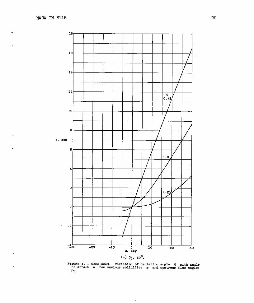
Effect of 5. - The deviation angle b cannot be predicted ingeneral for flow of a real fluid. However, the deviation angle for in-compressiblepotential flow can be obtained by means of the method de-scribed in reference 9. The results of the analysis presented in ref-erence 9 indicate that
5 =.tan
[
2X sinm‘ltan(a+~) -
1
- !3bCOS(CL+ fl.J X4 + 2X2COS 2pb + 1
(14)
The parameter x Is related to the cascade solidity a and the bladeangle by the following equation:
Thus, 5 is a function of
and a by equation (4).values of ~1 and a is
to 80° extends onlyto a
+ 2X2 COS z~b+l + 2x COS ~b+
12-x
2X sin ~tan-l b (15)
4 + 2X2 Cos 213b+ 1
a, j31,and a, since ~ is related to ~1
The variation of 5 with a for variousshown in figure 4. The curve for 131 equal
equals -~, since the solution beyond thisvalue is difficult to obtain and is of little interest.
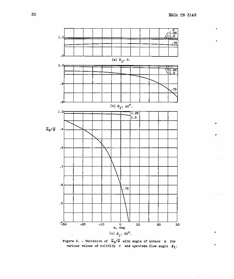
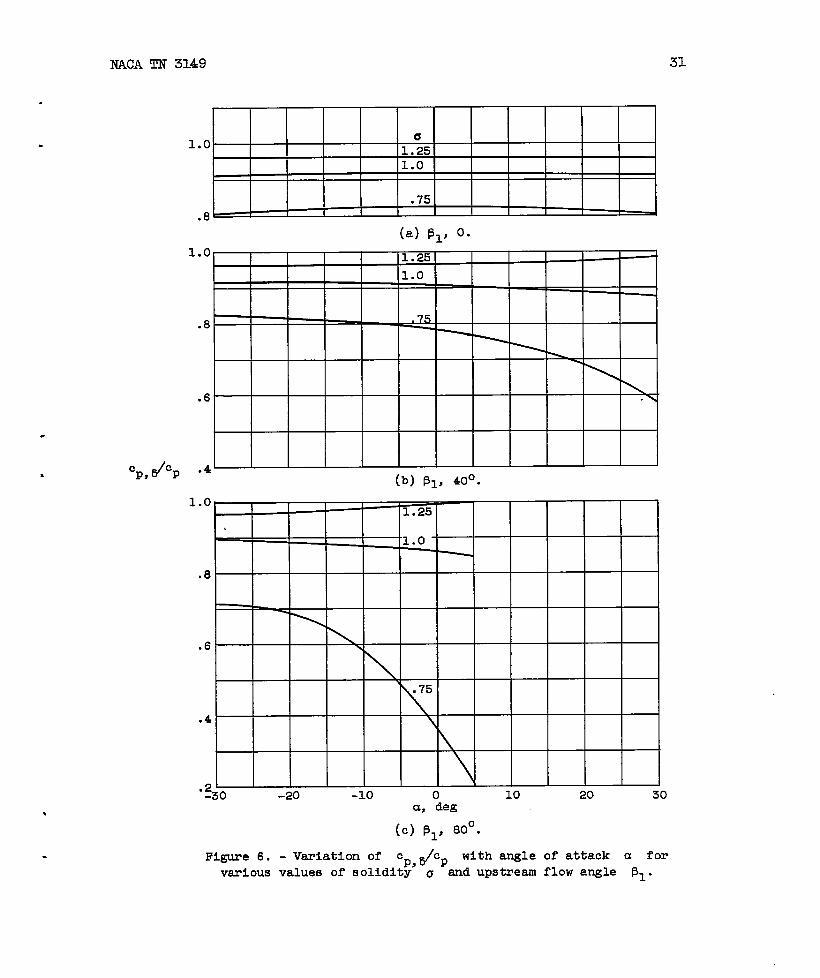
The ratios %,sll? and Z@ indicate the effects of 5 in that
these are the ratios of the pressure coefficients with 8 taken into
.
—

y
E.
.
NACA TN 3149
account to the pressure coefficientsare given by the following equations
cp,5 _
CP
sin(a,-
9
with 5 assumed zero. These ratiosfor incompressible flow:
5) Ccm(fl, - Lz)r-,.\
1USb cos2(P1-a) cos2(p1-*)-2cosBltan(p1-u)sin(a-5)cos(@1e5)-cos2pl 1—=E 2P1cos2(~1-aA%)[cos2(~1-a)-2sin(~1-m)cos~lsina-cos
1(17)
As a approaches zero, b also approaches zero and the right sides ofequations (16) and (17) beco~ indeterminate. These indeterminate formswere evaluated by L~Hospitalts rule, and the following expressions wereobtained for the limits approached by these functions as a approacheszero:
(19)
Equations (16), (17), (18), and (19) were solved with the use of thedata shown in figure 4. The results of these calculations are shown infigures 5 and 6. These results are merely indications of the trendsand the order of magnitude of the effects of 5, since the values of 5used were obtained assuning potential flow. Figures 5 and 6 indicatea nm.rkedincrease in the effect of 5 as the cascade solidity decreasesbelow 1.0.
Compressible Flow
In appendix B an analysis is carried out for subsonic compressibleflow similsx to that for incompressible flow. .The final equations arepresented in the following section:
Equations. - The expression for the downstream Mch nuniber ~ is
M22= - B+~~2A (20a)
HACA TN 3149
in which
COS2 5 cosqp~ -r2
CL+5)
Cosqfll - a)
1
-[
Cos(pl - u + 5)B=
l+~M12 MI COS ~1
Thus the downstream Mach number is
+
+
2TM1 COS(~l -
1
a+b)cosa
Cos(pl - al
‘1
J
seen to be a function &f the upstreamMach numiberin addition to the upstream flow angle, angle of attack, anddeviation angle.
When the downstresmlkch number has been obtained from equations(20a) and (20b), the static-pressurecoefficient can be found by mansof the folhwing equation:
Because M2 is a function of the upstream flow conditions and the devi-—ation angle, it can be seen from equation (21) that the static-pressurecoefficient also is a function of the upstream flow conditions and thedeviation angle.
The quantity ~ is a ratio of the’static-pressure change across
the blade row to the difference between the upstream total and staticpressures. For the incompressible case, this ratio is the same as theratio of the static-pressure change to the upstream velocity head. How-ever, for compressible flow, the upstream velocity head is a function
.
.

.
NACA TN 3149 U
not only of the &ifference between the upstream total and static pres- .,sures but also the upstream Mach number. The static-pressure coefficientcp,q e~ressed as a ratio of the ~stream velocity head is dkfined by
cPYq= (?2;-
where g is the acceleration due tocan be seen that ~ is related to
The right side of eqpation (23) is a
/
P~(wi)2(Pi - Pi) ~g =
/
Pi(wi)2Pi) Zg (22)
gravity. From this definition it
%,qas follows:
./
Pi(w~)2Pi) “Zg (23)
function of Ml and is given by
Y
k+%+$’-’-~E22%
Ml is shown in figure 7. ThisThe variation of this function with
function ~, q/~ is independent o? any -tifects of 5 as Is obvious
from its definition..
The total-pressure loss coefficie–nt ~ can be found fromlowing equation, which is derived in appendix B:
.
1- (, +y %2)=Simikr to the case for ~, a total-pressure
expressed as a ratio of the ups%eam velocity headfollows:
●
. /
P~(wi)2Eq = (Pi - P~) Zg
the fol-
(25)
10ss coefficient
can be defined as
(26)
12 NACA TN 3149
The expression for the ratio ?i@5 is the same as that far cp,q/cp.
given in equation (23). The variation of this function with Ml is
given by equation (24) and is shown in figure 7. .
Effect of 8. - A considerably more elaborate computation is re-quired to obtain the compressible potential-flow deviation angles thanwas reqpired for the incompressible case.
—Consequently, it is not
practical to compute even approximately the effect of 5 as was donefor incompressibleflow. However, the effect of b is probably of thesame order of magnitude for compressible flow as for incompressibleflow.
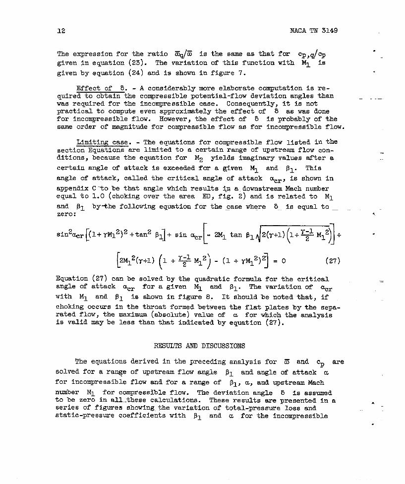
Limiting case. - The equations for conqressible flow listed in thesection Equations are litited to a certain range of upstream flow con-ditions, because the equation for M2 yields imaginary values after a
certain angle of attack is exceeded for a given Ml and P1. This
angle of attack, called the critical angle of attack acr, is shown in
appendix C-to be that angle which results in a downstream Mach numberequal to 1.0 (choking over the area ED, fig. 2) and is related to Ml
and ~~ by~he following equation for the ~ase where b...is equal to _ ._zero: *
[sin2%r (l+yM12)2+tan2 PI]+ sin ctcr
[
. 2M1tan ~1~~~+ -
[ (2M12(r+~)1 + ~ M12’-) 1(1 + TM12)Z = O (27)
Equation (27) can he solved by the quadratic formula for the criticalangle of attack acr for a given Ml and 131.
—The variation of acr
with Ml and ~1 iS shown in figure 8, It should be noted that, if —choking occurs in the throat formed between the flat plates by the sepa-rated flow, the maximum (absolute) value of a for which the analysisis valid may be less than that indicated by equation (27).
RESULTS AND DISCUSSIONS
‘Theequations derived in the preceding analysis for ~ and Cp are
solved for a ra~e of upstream flow angle j31 and angle of attack a
for incompressibleflow and for a range of ~1, a, and ~stream Mach
number Ml for compressible flow. The deviation angh 5 IS assumed
to be zero in all..thesecalculations. These re suits are presented in aseries of figures showing the variation of total-pressure loss and
A
static-pressure coefficientswith 131 and a for the fncompressible.
NACA TN 3149 13
.case and with ~~, a, and Ml for the compressible case. As previously
indicated in the section FreMminary Considerations, the total-pressure. losses obtained by this method represent an upper limit toward which the
losses in an actual cascade of sharp-nosed blades tend.
IncompressibleFlow
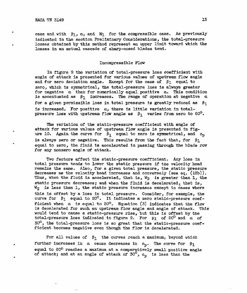
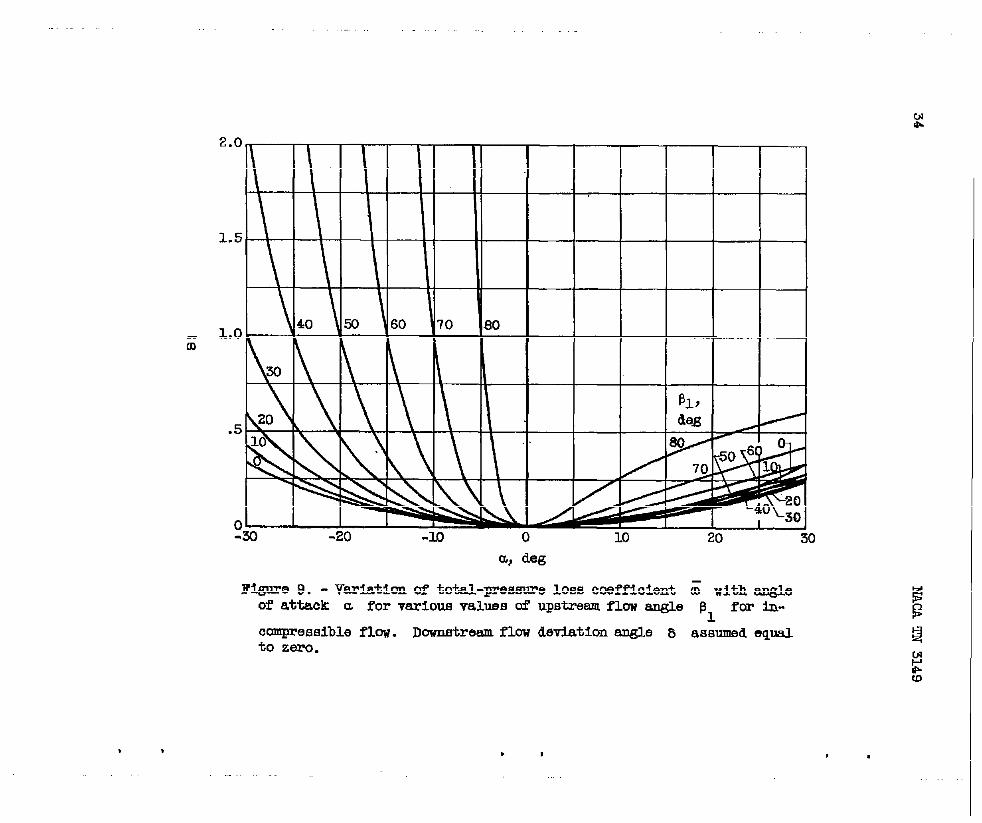
In figure 9 the variation of total-pressure loss coefficient withangle of attack is presented for various values of upstream flow angleand for zero deviation angle. Except for the case of ~~ equal to
zero, which is symmetrical, the total-pressure loss is alwa~ greaterfor negative u than for numerically equal positive cc. This conditionis accentuated as ~1 increases. The range of operation at negative a
for a given permissible loss in total pressure Is greatly reduced as pl
is increased. For positive a, there is little variation in total-pressure loss with upstream flow angle as 111 varies from zero to 60°.
The variation of the static-pressure coefficieti with angle ofattack for various values of ~stream flow angle is presented in ffg-.ure 10. Again the curve for 131 equalto zero is symmetrical, and ~
is always zero or negative. This results from the fact that, for PI.
equal to zero, the fluid is accelerated in passing through the blade rowfor any nonzero angle of attack.
Two factors affect the static-pressure coefficient. Any loss intotal pressure tends to lower the static pressure if the velocity headremains the same. Also, for a given total pressure, the static pressuredecreases as the velocity head increases and conversely (see eq. (~)).Thus, when the fluid is accelerated, that is, W2 is greater than 1, thestatic pressure decreases; and when the fluid is decelerated, that is,W2 is less than 1, the static pressure increases except in dases where
this is offset by a loss in total pressure. Consider, for example, thecurve for PI eqy.a.lto 20°. It indicates a zero static-pressure coef-ficient when a is equal to 20°. Equation (3) indicates that the flowis decelerated for such an upstream flow angle and angle of attack. Thiswould tend to cause a static-pressure rise, but this is offset by thetotal-pressure loss indicated in figure 9. For PI of 20° and a of30°, the total-pressure loss is so great that the static-pressure coef-ficient becomes negative even though the flow is decelerated.
For all values of P1 the curves reach a maximum, beyond which
. further increases in m cause decreases in %“ The curve for f31
equal to 80° reaches a maximum at a comparatively small positive angleof attack; and at an angle of attack of 30°, ~ is less than the.
14 NACA TN 3149
corresponding value for P1 equal to 60°. These phenomena occur for
the same reason as discussed in the preceding paragraph.
CompressibleFlow
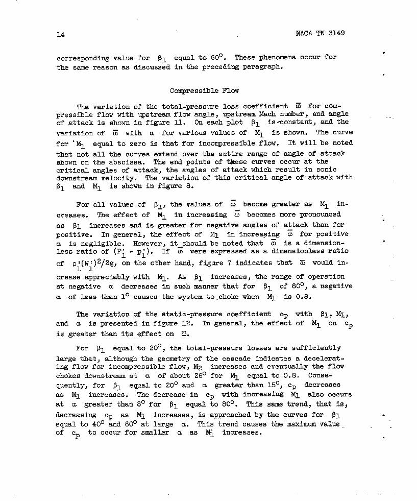
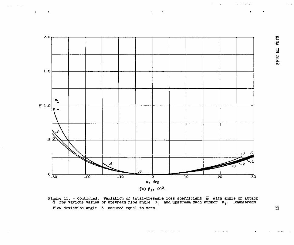
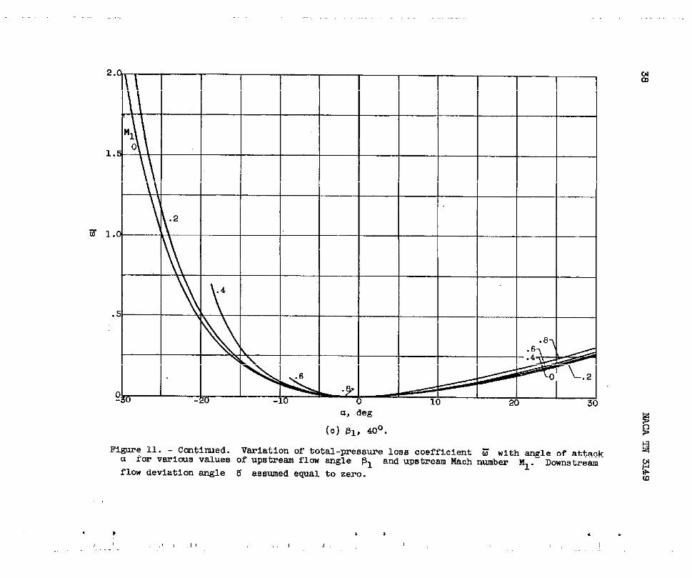
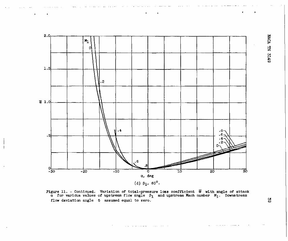
The variation of the total-pressure loss coefficient ~ for com-pressible flow with upstream flow angle, upstream Mach nmiber, and angleof attack is shown in figure I-1. On each plot PI ismonstant, and the
variation of 6 with a for various values of Ml iS shown. ~ curve
for ‘Ml equal to zero is that for incompressibleflow. It will be noted
that not all the curves extend over the entire range of angle of attackshown on the abscissa. The endpoints of t&ese curves occur at thecritical angles of attack, the angles of attack which result in sonicdownstream velocity. The variation of this critical angle of”attack with131 and Ml is shoti in figure 8.
For all values of i31,the values of m beco~ greater aS Ml in-
creases. The effect of Ml in increasing Z becomes more pronounced
as 131 increases and is greater for negative a~les of attack than forpositive. In general, the effect of MI in increasing Z for positive
a is negligible. However, it_should be noted that ~ is a dimension-less ratio Of (Pi - p~). If o were expressed as a dimensionlessratio
of p~(W~)2/2g~ On the other hand.>figure 7 indicates that Z6 wofid in-
crease appreciably with Ml. As 131 increases, the range of operationat negative a decreases in such manner that for j31 of 80°, a negative
a of less than 1° causes the system to.choke when Ml iS 0.8.
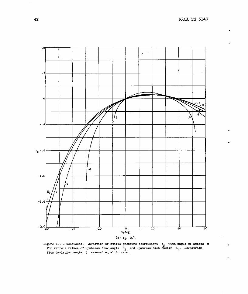
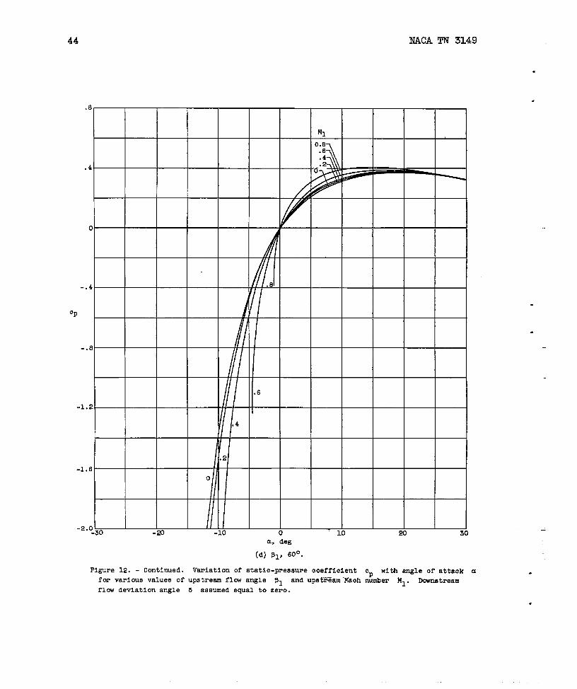
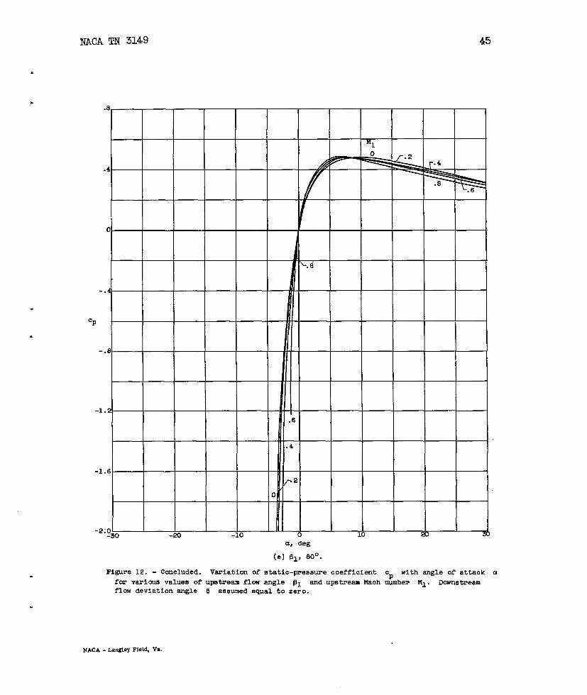
The variation of the static-pressure coefficient ~ with 131)MI,
and a is presented in figure 12. In general, the effect of Ml on ~
is greater than its effect on 6.
For PI equal to 20°, the total-pressure losses are sufficiently
large that, although the geometry of the cascade indicates a decelerat-ing flow for incompressibleflow, M2 increases and eventually the flmchokes downstream at a of about 26° for Ml equal to 0.8. Conse-
quently, for j31 equal to 20° and a greater than 15°, ~ decreases
as Ml increases. The decrease in Cp with increasing Ml also occurs
at a greater than 8° for P1 equal to 80°. This same trend, that is,
.
.
—
decreasing Cp as Ml increases, is approached by the curves for 91 .
equal to 40° and 60° at large a. This trend causes the maximum valueof Cp to occur for smaller a as M~ increases.
*
NACA TN 3149
.
15
SUMMARY (l?KESULTS AND CONCLUSIONS
A method of computing the losses in total pressure caused by a non-.zero angle of attack at the inlet to a row of sharp-nosed blades is de-veloped for both incompressible and subsonic compressible flow. Themethod is based on moment= considerations across a row of zero-thicknessflat plates. The results of the anal~is are presented in a series offigures showing the variation of the total-pressure loss coefficient ~and the static-pressure coefficient ~ with upstream flow angle ~1
and angle of attack a for incompressibleflow and with ~1, a, and up-
stream Mach nuniber Ml for compressible flow. The downstream flow de-
viation angle was assumed to be zero in all cases for the computations.These figures and the equations from which they were obtained indicatefor the range of variables and conditions considered that:
1. Increases in 131 cause sharp rises In ~ aridcorresponding
drops in ~ for negative m, but for positive u and 131 less than
60° there is little variation in ~ with ~l.
. 2. Increases in Ml cause only slightly higher values of ~ for
positive a.
3. A maximmn value of Cp occurs for a given value of ~1 at acertain positive value of a.,beyond which further increases in a re-sult in decreases in Cp due to total-pressure losses. The value of aat which this maximum ~ occurs decreases as Ml increases.
Lewis Flight Propulsion LaboratoryNational Advisory Committee for Aeronautics
Cleveland, Ohio, July 20, 1954

16 NACA TN 314S
APPENDIX A
SYMBOLS
The following symbols me used in this report:
A,B
a
c
‘%
‘%>~
DEFGHIJ
dA
Fb
g
L
M
n
P
P
R
T
t
u
v
functions of Ml, Plj mj and 5 (eq. (20b))
local speed of sound
function of Ml) Pl> a, and 5 (eq. (Cl))
static-pressurecoefficient, nondimensional (eq. (2a))
static-pressure coefficient expressed as nondimensional ratioof wpstresm dynamic pressure (eq. (22))
points around control surface, fig. 2
differential element of control-surfacesrea, nondimensional
blade force, nondimensional (eq. (1))
acceleration due to gravity
distsace normal to x-axis between adjacent stagnationstreamlines,dimensional
Mach number, nondimensional
unit normal to control surface, p6sttive-directionisoutward
total pressure, nondimensional (eqD (1))
static pressure, nondimensional (eq~ (1))
gas constant
total temperature
static temperature
velocity component in x-direction, nondimensional (eq. (1))
velocity component in y-direction, nondimensional (eq. (1))
.-
.
.

NACA TN 3149
.w resultant
. X9Y Cartesian
17
velocity, nondimensional (eq. (l))
coordinates, nondimensional (eq. (1))
a angle of attack (eq. (4))
B flow direction, positive in counterclockwise direction frompositive x-tiis
% blade direction, positive inpositive x-axis
r ratio of specific heats
countercloclmise direction from
5 flow deviation angle, angle between blade direction and down-stream flow direction, positive in countercloclnrisedirec-tion from blade direction (eq. (5~)
y P fluid weight density, nondimensional (eq. (l))9u E total-pressure loss expressed
p; - P+ (eq. (~)jA L
. Z total-pressure loss, expressedq stream dynamic pressure (eq.
Subscripts:
1 conditions
2 conditions
Cr conditions
as nondimensional
as nondimensional(26))
.
infinite distance upstream of cascade
downstream of leading edge
when ~ is equal to 1.0
ratio of
ratfo of up-
s shock component of velocity as in ref. 3 (see fig. 3 of thisreport)
6 flow deviation angle taken into account
Superscripts:
t dhensional value of quantity
vector quantity
.
-.
——-
18 NACA TN 3149
*
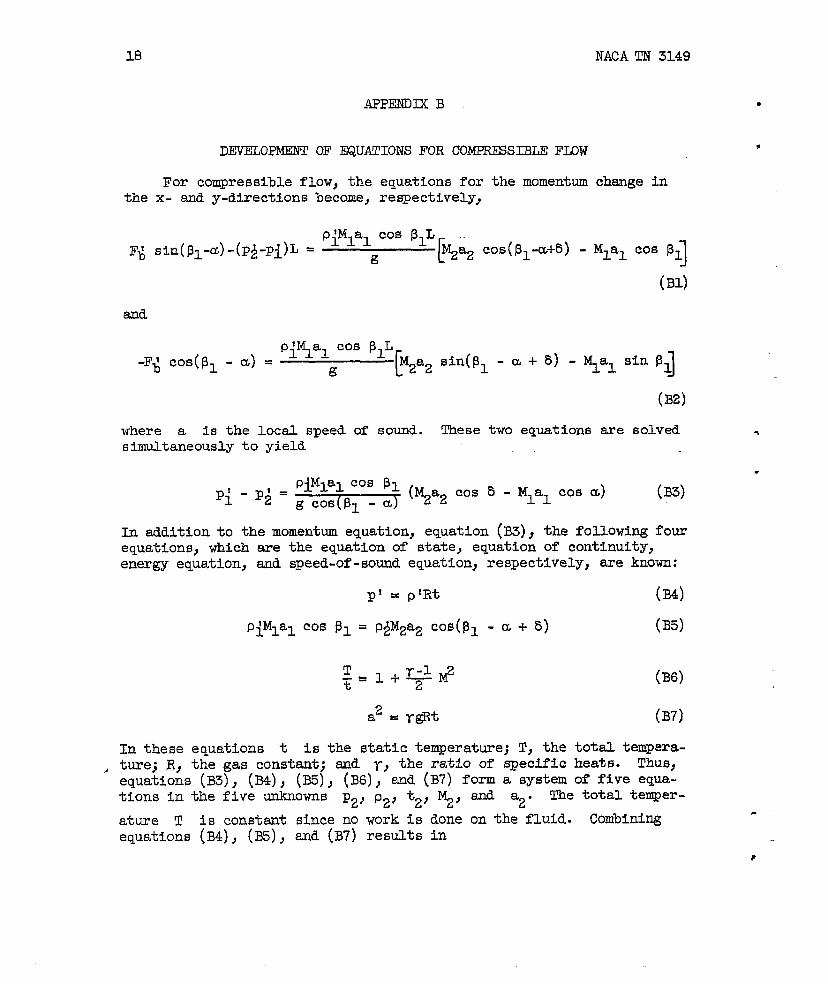
DEVELOPMENT OF
For compressible flow,
@UATIONS FOR COMPRESSIBLE FE3W
the equations for the momentum change inthe x- and y-directions become, respectively,
where a is the locel speed of sound.simultaneously to yield
(B2)
These two equations are solved
piMlal cos PIPi -P;= (~a2 cos 5- Mlal cos a) (33)
g cos(p~ - a)
In addition to the momentum equation, equation (33), the following fourequations, which are the equation of state, equation of continuity}e&rgy equation, and Speed:of-sound equation,
p! = plRt
p~M1al cos 131= P&&@ COS(131
T%
In these equations t is the
respectively} are known:
(34)
a+5) (B5)
(B6)
(B7)
static temperature; T, the total tempera-t~ej R, the gas constant; end r, the ratio of mecific heats- ThUsSequations (B3)J (34)} (35), (B6)J sad (B7) form a system of five equa-tions in the five unknowns p2, p2, t2, ~, and a2. The total temper-
ature T is constsnt since no work is done on the fluid. Combiningequations (B4), (35), and (B7) results in
.
.
.
?
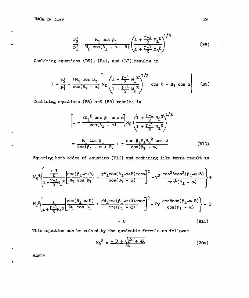
NACA TN 3149 19
(B8)
Conibiningequations (B3), (B4), and (B7) results in
Conibiningequations (B8) and (B9) results in
Ml Cos p= Cos 91M~M22 co’ 5+r (B1O)
= Cos(pl - a+5) Cos(pl - a)
Squaring both sides of equation (B1O) and combining like terms result in
d2
TMICOS(P1-U+5)COSm+ -1-2
Cos(pl - al
)1
2+m~cos(P&@cosa -a
Cos(pl - u
=0
This equation canbe solved by the quadratic formula
.
where
c
M22 = -2A
}
COs%cosq$p-la) +
Cosqpl - a)
)}cos&os(Bp’fa) - ~
Cos(pl - cc
(Bll)
as follows:
(20a)

20 JWCA TN 3149
p+
[
Cos(pl - a + 8)A= +
l+~M12 Ml COS ~1
TM1 COS(~~ -
1
a+b)cosa 2
Cos(pl - al
‘1
Cos b cos(j31- a+ 5)w Cos(pl - a)
Only the positive sign is showncause the negative sign results
before the radical in equation (20a) be-either in imaginary values of M2 or in
real values of M2 that indicate a decrease in the entropy of the fluidin passing through the blade row. Neither of,these is admissible.
Equations (20a) and (20b) determine the downstream Mach nuniber M2as a function of the upstream Mach nuniber,the flow direction, the angleof attack, and the downstream flow deviation angle. When M2 is ob-tained, the static-pressure coefficient,which is defined as
can be obtained. The ratio p~/Pi can be eqressed as a function of the
assumed known quntities by means of eqpation (B8). The total -pressureat a point is the pressure that the fluid would assume if it were de-celerated isentropicallyto a stagnation condition. Therefore,
The static-pressure coefficient thus becoms
(B12)
“
.—
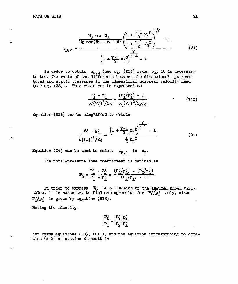
NACA TN 3149 ZL
In
to know
CL. =&,o
(21)
order to obtainthe ratio of the
~,q (see eq. (22)) from ~, it is necessary
difference between the dimensional upstreamtotal and static pressures to the dimensional upstream veloci& head(seeeq. (23)). ‘~is ratio canbe expressed as-
p: - P-! (p:/P:) - ~J. L
~.. L
P;o’q)% = P~(wi)2/@~g
Equation (B13) can be simplified to
pi-’i .~
Pi(wi)2/2f3 5 %2
. (B13)
(24)
Equation (24) canbe used to relate %P,q ‘0 %“
The total-pressure loss coefficient is defined as
Pi -PA (Pi/pi) - (Pflp~)~=pi
-P~= (pf pf) - 1
d 1
In order to express ~ as a function of the assumed hewn vsri-ables, it is necesssry to find an expression for P~pi only, since
p~/Pi is given by equation (B12).
Noting the identity
and using equations (B8), (B1O), and the eqyation corresponding to equa-tion (B12) at station 2 result in
.

NACA TN 3149
Thus, the eqution for ~ is
Y+l
1-
%=\ z ~/
Y
(B14)
(25)
.
.
.
.
.
.

NACA TN 3149 23
APPENmx c
DERIVATION OF EQUATION FOR’CRITICAL ANGIE Cl?ATTACK
Equations (20a) and (20b) yield real values for the downstream Machnumber ~ for all values of a, ~1, 5, and Ml such that
B2+4A~o
C=*L ‘;’Os”-+‘/
In order to solve
ceeded results inMl and 131,B2 +
\bA)
for ~r, that is, the angle of attack which if ex-
equation (20a) yielding imaginary roots for a given4A is set equal to zero and the resulting equation
.- solved for u. The value of a obtained from this equation is Gcr.ThuR
.B2+4A=O=
( )(c-a) 2+4&c-#
This equation simplifies to
~2 - 2(y+l) c = o
which has the roots
C=o
c = 2(y+l)
If C is equal to zero, equation (20a) indicates that M22 is negative.
Zero, therefore, is an extraneous root. If C is equal to 2(y+l),equation (20a) indicates that ~ is eqyal to 1. The limiting condi-
tion, therefore, is reached when the downstream flow is choked. In orderto find the relation among mcr> MI> and Pl, C is set equal to 2(T+1)
and the resuiting eqpation solved for u. For a given Bl, 5 is a func-
tion of u for a given cascade and is, therefore, not an independentvariable. Thus,
.

24 NACA TN 3149
If 5 is ass-d equl to zero,quadratic equation for sin ~rformula:
[ 1sin2acr (1+YM12)2 + tan2P1 + sin
this equation yields the followingwhich can be solved by the quadratic
‘cr[
- 2Ml tart~1~~$’+
1.
2.
3.
4.
5.
6.
7.
8.
9.
[ (2Mp (y+l) 1 ++12 ) 1- (1+ TM12)2=0
REFERENCES
(27)
Milne-Thomson, L. M.: Theoretical Aerodynamics. D. Van NostrandCo., Inc., 19,47.
Hamrick, Joseph T., Mizisin, John, and Michel, Donald J.: Study ofTlmee-Dimensional Internal Flow Distribution Based on Measurementsin a 48-Inch Radial-Inlet Centrifugal Impeller. NACA TN 3101, 1954.
Spannhake, Wilhelm: Centrifugal Pumps, ‘l?urbines,and Propellers. TheTechnology Press, M.I.T. (Cambridge},1934.
Stodola, A.: Steam and Gas Turbines. McGraw-Hill Book Co., Inc.,1927. (Reprinted,Peter Smith (New York), 1945.)
Kochendorfer, Fred D., and Nettles, J. Cary: An Analytical Method ofEstimating Turbine Performance. NACA Rep. 930, 1949. (SupersedesNACARME8116.)
Birkhoff, Garrett: Hydrodynamics. Princeton Univ. Press, 1950.”
Greenhil.1,G.: Report on the Theory of a Stream Line Past a PlaneBarrier, and of the Discontinuity Arising at the Edge, with anApplication of the l?heoryto an Airplane. R. & M. No. 19, BritishA.R.C., 1910.
Michell, J. H.: On The theory of Free Stream Lines. Phil. Trans.Roy. Sot., ser. A, vol. 181, 1890, pp. 389-431.
Durand, William Frederick: Aerodynamic Theory. Vol. II. DurandReprinting Comm. (C.I.T.), 1943, pp. 91-96.
—
.

NACA TN 3149 25
.
.
(8) Diridil.etfbti.
IResultantfcu’oe(lift) normaltoundisturbedflewdtieo%iCm
(b) Joukowski
Lift
t
(c) I&ee.streamlineflow.
Figure1. - Threeidealflowspast an inclined flat plate.

26 NLLCATN 3149
Figure2. - Controlsurfacein flow field.
%
Figure3. - Velocityvectordiegramshowing“shock”velocitycomponent W~of reference3.
.
#
.
r

NACA TN 3149 27
5, deg
-.
.
6
4
0.:5
2/
1.0/ ~
o
// /
-2,“ ‘ /
-4
-6-30 -20 -lo 0 10 20 30
CL,deg
‘(a)Pl, o.
Figure4. - RAaticm of deviationangle 8 with angle of attack u forvarioue solidfties u adl upetmxm.flou aagl.es PI.
,
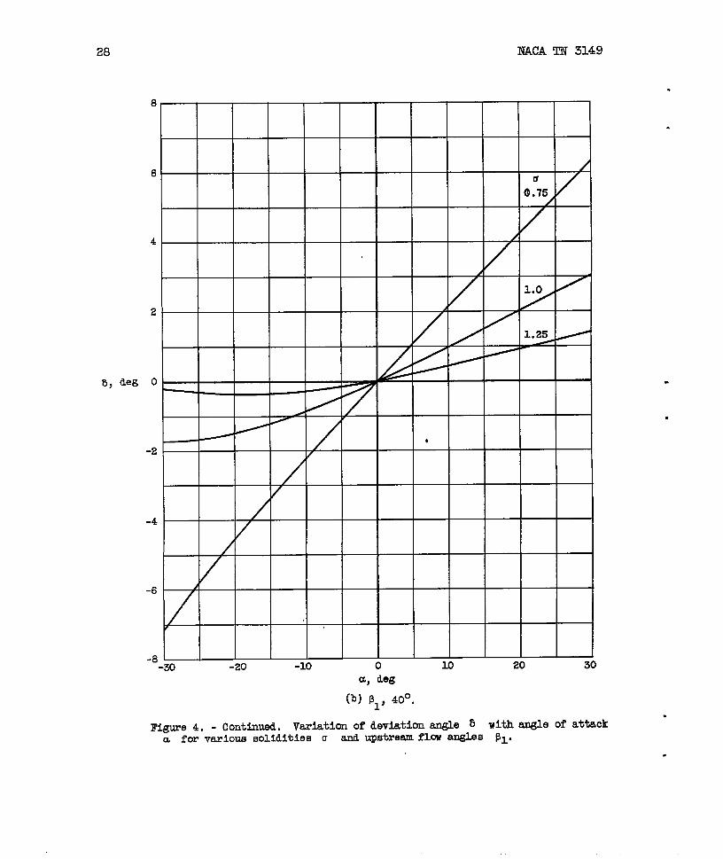
28 NACA TN 3149
8, deg
8
6 /
4
2
0
*-2
-4
-6 1
R
-8-30 -20 -lo 0 10 20 30
CL,deg
(b) ~1, 40°0
Figure4. - continued. Vaxle.tlxmof devlatlonangle b with angle of atiacka for vexiolleEIollditiesu and Upstrwm flml -s 131.
.
.
.
,
.
.
NACA TN 3149
18
16
14
127a
o.75}
10
8 I‘
6, de~
6- 1
1.0/
4/
/
2 /
-2
t
-4-30 -20 -10 0 10
a, degm 30
(c)51, 80°.
Figure4. - Concluded.Verlatlonordevla~lonangle &iwithangleof’attacka forvarlcueaolld~tlesB1.
IY andupstreamflowangles
NACA TN 3149
1.0 . — . — — — — — . —
.75
.9 -
(a) PI, 0.
.9
.8
(b) PI, 40°,
1.0
1.0
.9
.8
\
.7
.6
.5
.4-30 -20 -lo 0 – 10 20 30
a, deg
(c) PI, 80°.
Figure 5, - Variationof ~@ wllhangleofattack a forvsrlousvaluesof solidityo andupstreamflowangle PI.
NACA TN 3149 31
.
.
‘p, A
1.0 1.25
1.0— .
.8 75 _
\
.6 \
.4—(b) ~1, 40°.
1.0
.8
.6
.4
.2-30 20
Figure6.various
-20 -lo 0 10a, deg
(c) PI, 80°.
- Variationof cp,~p wlthanglevaluesof solidity u and upstream
of attackflow angle
30
a for

. .
wN
1.5.
1.2
1.1
0=
1.0 ~.o .2 .4 .6 .8 1.0
Ml
mgure 7. - Variation of ratio of ~s~resm total and staticpressure differenceto upstrasm dynamic Premmrs
‘/
Pi(lii)2(~i-Pi) ~ With upstreamMmh number Ml.
.,
!2
I
I
,

NACA TN 3149 33
●
✎
a
.
.
80Ml
/
60 /
/ / /
40 k/
/
20/
●
.8~ ~
-20
-40/.4
-60
-mo 20 40 60 80
Figure 8. - Veriatim of critioe.1angle of attmkccOr with upstreamflow angle 131 for various
valuesof upstreamMaohnumber Ml. Downstreamflowdeviationangle 6 aesumedequalto zero.
, *
PI,(leg
/ ‘80
20 3010
a, &g
Figure 9. - V=iaticm Of totd.-p%l~e 10sS Coefficientof attack a for mrlow values of upatrearaflow angle
compressibleflow. Ixwnstream flow deviationangle ijto zero.
.,
; with angle
PI far in-
amnmed eqwd
.

NACA TN 3149 35
.
.
.8
.4
0
-. 4
‘P
-. 8
-1.2
-1.6
-2.0.
\/
/ / \
o 10
/ ‘/c
\
i1
/
/
/ I //
30 -20 -lo 0 10 20 30
a, aeg
Figure10. - Vartiticmof static-pre6suremefflcient CP with angle of
attack a for variouevalues of upstreamflow angle 131 for incom-
pressibleflow. Dwnetream flow deviation angle 5 aseumed equal.tozero.
,

2.0
1.5
.
r) 1.0
.5ml
o
0 .-30 -Xl I
1
.8
a, deg
(a)PI, 0.
Figure 11. - Variationof total-pressure106s coeff~oientverlausvaluesof ups~rem r1ow angle PI anclUP6 txeem
.2.6 .,4
Y
30
G with angleor attack u ra#lschnumber Ml. Dmnmtream flm
devlatlanangle 5 assumedequal to zero.
, .
.,,
2.0
1.5
G 1.0
.5
0
u, deg
(b) ~1, 20°.
30
F@llre 11. - Continued.
a for various value.9
flow deviation augle
Variation of total-preosme 10SB coefficient ~ with angle of attackof upstream flew angle f31 and upstream Mach number ml. Downatreem
5 assumed equal to zero.
‘1
1.50
3 1.0
.5 \
T
a, deg
(a) ~~, 40°.
Figure 11. - Ccmtlmed.
a for verlcus valueB
flow devlatlon angle
)
,1 .’ I ,J,
Variation of total-pressure loss coefficient ~ with angle of attaok
of ups treem flow angle pl and ups tream Mach number Ml. Downs tpeam
6 aSB~ed eqUal to zero.
,3 . .
,. I .1. , 1, ,, I
,, . *
2
1
.0
!41
o
\
.5 I
.0
,5
0-30 -20 -lo 0 10 z
Figure 11. - Continued.
a for various values
flow deviatlan angle
a, deg
(d) !31, 60° -
.8
.6
::
30
Veriati. on of total-presauze lMS coefficient = with engle of attack
of upstream flow angle PI end upstream Mach number Ml. Downs tream
6 eesumed equal to zero.

2.0
1.:
?3 1.C
.:
c
-1--
)
k$
0
$-10
2
a, deg
(e) ~1, 80°.
Figure 11. - Concluded. Vwlation of total-pressure lose coefficient = with angle of attack El
of upstream flow angle 131 and upstream Mach number Ml . Dome tream ~
5 aesumed equal to zero. - “k-W
a for varloue values
flow deviation angle
>
I
r

NACA TN 3149 41
.
.
.
CP
.
.
.8
.4
0
4-.Ml /
y
-.8
-1.2
1
-1.6
-2.0-5.-20 -10 0 10 20
a, deg30
(a) pl, 0.
Figure 12. - Varlatlon of static-pressure coefficient Cp with angle of attack a for varicua
vtiues of upstream flow angle 51 and upatreem Mach number Ml. Dcwnatream flo~ deviation
angle 6 assumed equal to zero..,
42 NACA TN 3149
.
.
.8’
/“
.4
0 - — — — — —
-.4 ,
‘P -“8
/
/
.6
-1.2 /
o-1.6
/
/
I
-2.0--30 -20 -lo 0 10
.6.%
\
) 30
Figure 12. - Continued.
for varl OUE values of
flow deviation angle
a,deg
(b) 51, 20°.
Variation of 8tatla-preOsure coefficient
UPS tmaam flaw angle PI and upatreem ~ch
8 aeeumed equal to zero.
CPwith angle of attack a
number Ml. Mwnetreem
.
●
✎

.8
.4
4-.
CP
-.a
-1.2
0
-1.6 /
-2.g50 //-20 -10 0 10 m 30
Figure 12. - Continued.
for varicxta values of
flew deviation angle
a, deg
(c) p~, 400.
Veriation of ❑tatlc-pressure coefficient
upetreem flow angle ~1 end upstream Uach
6 aesumed equal to zero.
CPwith angle of attacka
number Ml. Downstream
44 NACA TN 3149
.8
Ml
0.8.6.4
.4 .2
0
-.4
%
-.8
-1.2
/ ,4
I1/
.2
-1.6i
o
-2.0 --30 -a -lo 0 10 20 30
Figure 12. - Continued.
f’orvarious valuee of
flow deviation angle
a, deg
(d)p~,60°.
Variation of static-pressure ooefficlent
Upstreamflow angle pl and upstream ”llech
6 as%umed equal to zero.
CPwith angle of attack a
number Ml. Downstream
.
.
.
.
.?
.
.
..8
%
.4
0
~. 6
-.
‘P
-.8
-1.2
I .6
.4
-1.6 i
p 2
0
-2:0-30 -20 -lo 0 10 xl
a, deg
(e) 51, 80°.
Flare 12. - Concluded. Veriatlan of etatic-pressure coefficient
for various values of upetream flow angle pl and upetreem Mach
flew deviation engle 5 aseumed equal to zero.
‘P with angle of attack
number Ml. Dawna tre.em
a
NACA -LangleyField,Va.