Embed Size (px)
Citation preview
egkjktiqj, Xokfy;j & 474 005
Maharajpur, Gwalior - 474 005
CAMTECH/E/13-14/MM AC-DC EMU/1.0
Draft
Draft
Hkkjr ljdkj GOVERNMENT OF INDIA jsy ea=ky; MINISTRY OF RAILWAYS
MAINTENANCE MANUAL for
AC – DC EMU (SIEMENS) TARGET GROUP : AC-DC EMU (SIEMENS) MAINTENANCE STAFF
dsoy dk;Zky;hu mi;ksx gsrq
(For Official Use Only)

MMAAIINNTTEENNAANNCCEE
MMAANNUUAALL
ffoorr
AACC--DDCC EEMMUU ((SSIIEEMMEENNSS))

INDEX
Chapter No. Description Page
1. GENERAL DESCRIPTION 01 - 29
2. AUXILIARY CONVERTER UNIT (ACU) 01 - 09
3. TRACTION CONVERTER CUBICLE 01 - 11
4. TRACTION MOTOR 01 - 04
5. TRACTION TRANSFORMER 01 - 10
6. OTHER ELECTRICAL EQUIPMENT 01 - 13
7. CONTROL SYSTEM (SIBAS 32) 01 - 11
8. BOGIE 01 - 13
9. SUSPENSION 01 - 06
10. BRAKE SYSTEM 01 - 05
11. PASSENGER AMMENITIES 01 - 02
12. MAINTENANCE SCHEDULES 01 - 72
13. ANNEXURE 1 - REFERENCE DRAWINGS 01 - 43
14. ANNEXURE 2 – MUST CHANGE ITEMS 01 - 06

CHAPTER 1
GENERAL DESCRIPTION
CONTENTS
S.No. Description Page No.
1.0 INTRODUCTION 01
1.1 ABBREVIATIONS 01
1.2 THREE-PHASE TECHNOLOGY 02
1.3 CONTROL TECHNOLOGY 03
1.4 DISPLAY SUPPORT 03
1.5 AUXILIARY EQUIPMENT 03
1.6 UNIT & RAKE FORMATION OF EMU 04 1.6.1 End Basic Unit 04
1.6.2 Middle Basic Unit 04 1.6.3 Train Formation 05
1.7 MAJOR EQUIPMENT OF DTC 05 1.7.1 Driving Cab 05 1.7.2 Indication Panels 07
1.7.3 Electronics Cabinet DTC 12
1.8 MAJOR EQUIPMENT OF MOTOR COACH 14 1.8.1 Shunting Cab 14 1.8.2 HT Compartment 15
1.8.3 Roof Equipment 17 1.8.4 Under Frame Equipment 17
1.8.5 Panel in Passenger Area of Motor Coach 17
1.9 ELECTRICAL EQUIPMENT IN MOTOR COACH 17 1.9.1 Pre-Charging AC Contactor 17
1.9.2 Pre-Charging DC Contactor 17 1.9.3 Traction Converter Cubical 18
1.9.4 Earth Fault Detector 18 1.9.5 Line Filter 18
1.9.6 Auxiliary Converter Unit 18 1.9.7 Pantograph (Type AM-1882) 18
1.9.8 Surge Arrestor 18 1.9.9 Line Voltage Transformer 19

S.No. Description Page No.
1.9.10 Line Current Transformer 19
1.9.11 Voltage Sensing Device 19
1.9.12 Change Over Switch AC/DC 19
1.9.13 Braking Resister Rs 25.10 19 1.9.14 High Voltage AC Circuit Breaker (HVCB) 19
1.9.15 High Speed DC Circuit Breaker 19 1.9.16 AC Earthing Switch 19
1.9.17 DC Earthing Switch 19 1.9.18 Surge Arrestor AC 19
1.9.19 Surge Arrestor DC 19 1.9.20 Traction Motors 20
1.9.21 Traction Transformer 20
1.10 TRAILER COACH 20 1.10.1 Panel in Passenger Area of TC 20
1.10.2 Roof Equipment 20 1.10.3 Under Frame Equipments 20
1.11 NON DRIVING TRAILER COACH 20 1.11.1 Panel in Passenger Area of NDTC 20 1.11.2 Roof Equipment 20
1.11.3 Under Frame Equipments 20
1.12 TRANSDUCERS AND SENSORS 21
1.13 BRIEF DESCRIPTION OF HT POWER CIRCUIT 21
1.14 PANTOGRAPH CONTROL 24
1.15 MAIN CIRCUIT-BREAKER CONTROL 27
1.16 EARTHING SWITCH 28
1.17 EARTHING 29

CAMTECH/E/13-14/MM AC-DC EMU/1.0
Maintenance Manual for AC-DC EMU (Siemens) Chapter 1
1
CHAPTER 1
GENERAL DESCRIPTION
1.0 INTRODUCTION
The AC-DC EMU (Electrical Multiple Unit) is a newly designed train equipped with state-of-art IGBT control technology. These trains are especially designed for running over DC as well as AC territory in Mumbai sub-urban area to cater growing demand of passenger traffic. These vehicles are equipped with a driver’s friendly diagnostic display (MMI) unit.
This Maintenance Manual for AC-DC EMU (Siemens Rake) is prepared for the
use and reference for maintenance staff of EMU Car Sheds and Workshops. Maintenance and overhauling procedures of various electrical, mechanical equipment and all other accessories of Siemens Rake are briefly described in this manual.
1.1 ABBREVIATIONS
ACU - Auxiliary Control Unit ADC/COS - AC/DC Changeover Switch AFB - Automatic Traction/ Brake Control (Cruise Control AM - Shut Off Valve (Parking Brake Circuit) AWS - Auxiliary Warning System BCU - Brake Control Unit BW - Braking Resister CCU - Central Control Unit DCS - Driver’s control switch (Master key) DM - Diagnostic Message DTC Driving Trailer Coach EBU - End Basic Unit EBL - Emergency Brake Loop ES - Electronic Cabinet FML - Traction Motor Fan GTO - Gate Turn Off Thyristor HB - Main Air Compressor HBL - Main MR Pipe HL - Main Brake Pipe HSCB - High Speed Circuit Breaker HTC - High Tension Compartment IGBT - Insulated Gate Bi-Polar Transistor MBU - Middle Basic Unit MMI - Man Machine Interface MPS - Motor protective switch MS - Main Switch

CAMTECH/E/13-14/MM AC-DC EMU/1.0
Chapter 1 Maintenance Manual for AC DC EMU (Siemens)
2
MVB - Multi Vehicle Bus NDTC - Non Driving Trailer Coach PBC - Power brake controller PIS - Passenger Information System PT - Potential Transformer PTS - Position of Train System RDM - Rescue Drive Mode SB - Signal Bell SC - Shunting Cab SIBAS - Siemens Bahn Automatisierungs System SKS - SIBAS KLIP Station. SW - Software TCC - Traction converter cabinet TCU - Traction Control Unit VCB - Vacuum Circuit Breaker VSD - Voltage Sensing Device VVVF - Variable Voltage Variable Frequency
1.2 THREE-PHASE TECHNOLOGY
The vehicle is equipped with a state-of-the-art three-phase drive with asynchronous motor. The advantages over direct current drives are as follows:
Smooth (Step-less) acceleration.
Reduced weight
Wear-resistant drives hence less maintenance and high level of reliability as no wearable part like carbon brushes and commutator.
Good starting properties
High tractive force over the whole speed range
Wear-free regenerative brake for reduced maintenance, increased wheel and other mechanical component life and energy conservation as well
Easy starting even on gradients
The stator winding of the asynchronous motor consists of coils, which are electrically offset by 120°. If these are connected to a three-phase network, they generate a rotating magnetic field, also known as rotating field.
The rotor consists of one winding which is designed with rods whose ends are short-circuited by means of rings. This kind of rotor is therefore called short-circuit rotor.
A rotating magnetic field induces an electromagnetic force into the rotor winding. The electric circuit of the short-circuit rotor is always closed, thus creating a current flow which generates another magnetic field (rotor magnetic field). The rotor magnetic field attempts to catch up with the rotating field in the process. If the rotor rotates faster than the rotating magnetic field, the engine automatically switches into braking mode. This means that by changing the voltage and the frequency, the output (torque) and the speed (number of revolutions per minute) can be altered. The frequencies and the voltages are

CAMTECH/E/13-14/MM AC-DC EMU/1.0
Maintenance Manual for AC-DC EMU (Siemens) Chapter 1
3
generated in the current converter. The main components are the four-quadrant converter, the intermediate circuit and the pulse width modulation inverter.
In DC mode, the voltage is fed into the intermediate circuit via a line filter. The transformer and the four-quadrant converter are therefore not required. After an automatic commutation from AC to DC, the transformer cooling is automatically switched off.
In braking mode, the vehicle can feed the generated energy back into the contact line network. This is only possible if the network is able to receive the generated energy. If the network is not able to do this, the pneumatic brake is activated.
1.3 CONTROL TECHNOLOGY
There are two Central Control Units called CCU. These are located in the driver's
cab. Apart from the control of the entire train, the CCU also controls the display. The vehicles of one unit and the units themselves are connected to each other via an MVB bus. The MVB is designed redundantly with line A and line B. If the MVB bus is not available despite of this fallback, the vehicle can be operated in degraded operation via the rescue drive mode. This function is only used for clearing the track. In this operating mode, the display is switched off and the auxiliary tell-tale lamps are switched on. All switches, buttons and devices which are controlled via the control technology are connected to a KLIP station.
1.4 DISPLAY SUPPORT
The MMI (Man-Machine Interface) is installed in the driver's cab in the DTC and
informs the driver of the current state of all important functions in the train. The states of functions are indicated to the driver by means of coloured icons. The driver can detect faults at a glance. The display assists the driver during the subsequent error detection. For information on further actions, the driver can call up the corresponding remedy for the error message. Automatic vigilance device has been implemented via the master controller. If the driver releases the vigilance monitoring button during the journey, the brakes are applied automatically and the power of the train is switched off. This only happens during the journey. If the speed is below 5 km/h, this function is disabled. In rescue drive mode, the automatic application of the brakes is immediately initiated even if the vigilance monitoring switch is not actuated and if the speed is below 5 km/h.
1.5 AUXILIARY EQUIPMENT
The three-phase auxiliary equipment are supplied by an auxiliary inverter. The inverter for auxiliary equipment generates the following voltages:
415 Volt AC for fans / main air compressor and pumps
110 Volt AC for passenger compartment fans and lighting
110 Volt DC for the auxiliary air compressor, plugs, battery bus bar, instrument and emergency lighting. The inverter for auxiliary equipment supplies the three-phase components with a
fixed frequency (50Hz) and voltage. The auxiliary equipment is connected by means of contactors.

CAMTECH/E/13-14/MM AC-DC EMU/1.0
Chapter 1 Maintenance Manual for AC DC EMU (Siemens)
4
1.6 UNIT & RAKE FORMATION OF EMU
There are two types of basic units o End basic unit o Middle basic unit.
1.6.1 End Basic Unit
It consists of three coaches viz. Motor Coach (MC) Driving Trailer coach (DTC) Trailer Coach (TC)
Motor-Coach
This is the coach responsible for the movement of the EMU as desired by the driver command. This consists of propulsion equipment viz. transformer, traction motor, traction converters, (Four quadrant chopper), PWM inverters, brake chopper etc.
Driving Trailer Coach
This is non-powered coach with facilities for driving. These coaches are equipped
with Master/ Brake Controller, Drivers Desk, Passenger Information System, Light & Fans etc.
Trailer Coach
This is also non-powered coach but without Drivers desk. Passenger Information
System and Light & Fans are provided in this coach. 1.6.2 Middle Basic Unit
It consists of three coaches viz. Motor Coach (MC) Non Driving Trailer coach (NDTC) Trailer Coach (TC)
Non Driving Trailer Coach
This is non-powered coach without facilities for driving. These coaches are equipped with Light & Fans etc.
Figure 1 : End Basic Unit
Figure 2 : Middle Basic Unit

CAMTECH/E/13-14/MM AC-DC EMU/1.0
Maintenance Manual for AC-DC EMU (Siemens) Chapter 1
5
1.6.3 Train Formation
For the EMU, following train formations are possible:
(i) Nine Car Rake : It comprises of 3 basic units
(ii) Twelve Car Rake : It comprises of 4 basic units
(iii) Fifteen Car Rake : It comprises of 5 basic units (Only in WR)
1.7 MAJOR EQUIPMENT OF DTC
1.7.1 Driving Cab
1 Side panel left + RDM signal lights 7 Speedometer 2 Signal lights 8 Radio /PIS panel 3 Display, MMI 9 Side panel right 4 Pressure panel 10 Pneumatic control valve (master brake
controller) 5 Key switch and master controller 11 Wiper valve 6 Power brake controller 12 Horn valve
Figure 3: Nine Car Rake
Figure 4: Twelve Car Rake
Figure 5: Fifteen Car Rake
Figure 6: Driving cab
CAMTECH/E/13-14/MM AC-DC EMU/1.0
Chapter 1 Maintenance Manual for AC DC EMU (Siemens)
6
1.7.1.1 Driving Desk a. Brake controller b. Master controller
c. Left hand side panel for push buttons, rotary switches and indications.
d. MMI
e. Different gauges f. PIS
g. TMS (Train management system) h. Foot operated valve for hooter
i. AWS indication panel j. Analog speedometer
k. ESMON l. SIBAS KLIP Station (12 & 13)
m. Cocks for AWS 1.7.1.2 Guard’s Desk
a. Brake pipe pressure gauge b. Panel for push buttons
1.7.1.3 Electronic Cabinet
a. CCU b. Push buttons c. Rotary switches d. MCBs (1st layer & 2nd layer)
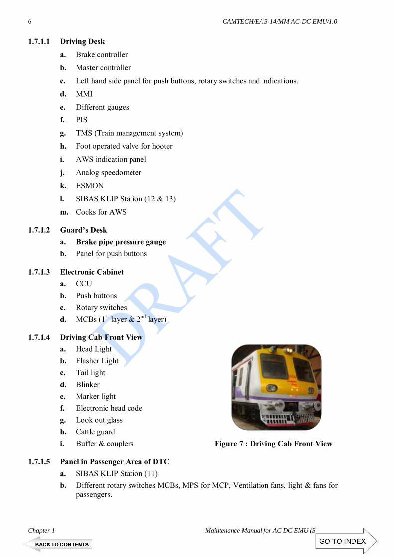
1.7.1.4 Driving Cab Front View
a. Head Light b. Flasher Light c. Tail light d. Blinker e. Marker light f. Electronic head code g. Look out glass h. Cattle guard i. Buffer & couplers
1.7.1.5 Panel in Passenger Area of DTC
a. SIBAS KLIP Station (11) b. Different rotary switches MCBs, MPS for MCP, Ventilation fans, light & fans for
passengers.
Figure 7 : Driving Cab Front View

CAMTECH/E/13-14/MM AC-DC EMU/1.0
Maintenance Manual for AC-DC EMU (Siemens) Chapter 1
7
1.7.1.6 Roof Equipment: a. Ventilation fans
1.7.1.7 Under-frame Equipment
a. Main compressor b. Battery box c. Different reservoirs d. Combined brake unit e. Parking brake equipment f. Air suspension equipment g. Mechanical weight transfer equipment
1.7.2 Indication Panels
1.7.2.1 Control Elements in the Driver's Desk on the Left-Hand Side
1. Mounting Plate 11. SB I (Signal Bell) 2. Flasher Push Button 12. Emergency Brake 3. Head Light Main / Auxiliary. 13. Emergency Off 4. Head Light On / Off 14. RDM Active 5. Audio visual push button 15. Fire Alarm 6. SB II Alarm bell (HW) 16. Spare 7. Head Light Bright / Dim 17. Minimum 1 Brake applied 8. Fire Alarm (Buzzer 18. Minimum 1 Panto up 9. Audio Visual (Buzzer) 19. Minimum 1 CB On 10. AWS vigilance 20. Lamp Test Driver
A. All switches/push buttons on this panel have metallic border
B. All indications on this panel have black border
Figure 8: Control Elements in the Driver's Desk on the Left-Hand Side

CAMTECH/E/13-14/MM AC-DC EMU/1.0
Chapter 1 Maintenance Manual for AC DC EMU (Siemens)
8
1.7.2.2 Auxiliary Tell-Tale Lamps
A 1 Not all Pantos up B 1 Emergency brake A 2 Not all main switches on B 2 Emergency OFF A 3 Spare B 3 Spare A 4 Min. 1 brake applied B 4 Fire Alarm A 5 Spare B 5 Spare A 6 Spare B 6 Spare A 7 Spare B 7 Spare
1.7.2.3 Pressure Panel
1. Brake Cylinder Gauge 2. MR/BP/Duplex Gauge 3. Panto Up / Down 4. Main Circuit Breaker On / Off 5. Cruise Control 6. Neutral Section Push Button
Figure 9: Auxiliary Tell-Tale Lamps
Figure 10: Pressure Panel

CAMTECH/E/13-14/MM AC-DC EMU/1.0
Maintenance Manual for AC-DC EMU (Siemens) Chapter 1
9
1.7.2.4 Man Machine Interface (General View)
1 Display ON / OFF 2 Not Connected
3 Legends of Symbols (Meaning) 4 Event Overview
5 Trouble Shooting Guidelines for Motorman 6 Not Connected
7 Brightness Control Dialog 8 Not Connected
9 Not Connected 10 Clear
11 Cursor Up 12 Cursor Down
13 Curser Left 14 Curser Right
15 Enter 16 to 25 Soft keys 0 to 9
Figure 11: Man Machine Interface (General View)

CAMTECH/E/13-14/MM AC-DC EMU/1.0
Chapter 1 Maintenance Manual for AC DC EMU (Siemens)
10
1.7.2.5 Train Radio and Passenger Information System
1.7.2.6 Control elements in the driver's desk on the right-hand side
1 Mounting plate 2 Cab tube light for driver 3 Cab spot light for driver 4 Cab emergency light for driver 5 Cab fan for driver 6 Parking brake release 7 Parking brake apply 8 PIS release button for microphone 9 PIS Microphone
1 PIS MMI
2 Train radio hands-free module
3 Train Radio MMI
4 Pressure Gauge Parking Brakes
5 Train radio Handset
Figure 12: Train Radio and Passenger Information System
Figure 12: Control elements in the driver's desk on the right-hand side

CAMTECH/E/13-14/MM AC-DC EMU/1.0
Maintenance Manual for AC-DC EMU (Siemens) Chapter 1
11
1.7.2.7 Guard Panel Right-Hand Side
1 Mounting Plate 2 Ventilation Release Off
3 Fan Release Off 4 Spare
5 Train Light 100 % Off 10 Flasher Light On / Off (Guard)
11 Tail Light On / Off 12 SB I Signal Bell (Guard) SW
13 SB II Alarm Bell (Guard) HW 18 Spare
19 Spare 20 Spare
21 Train Light 50 % Off 26 Cab Spot Light (Guard)
27 Cab Tube Light (Guard) 28 Cab Fan (Guard)
29 Lamp Test
Figure 13: Guard Panel Right-Hand Side

CAMTECH/E/13-14/MM AC-DC EMU/1.0
Chapter 1 Maintenance Manual for AC DC EMU (Siemens)
12
1.7.3 Electronics Cabinet DTC 1.7.3.1 Level 1
Figure 14: Electronics Cabinet DTC level 1

CAMTECH/E/13-14/MM AC-DC EMU/1.0
Maintenance Manual for AC-DC EMU (Siemens) Chapter 1
13
1.7.3.2 Level 2
Figure 15: Electronics Cabinet DTC level 2

CAMTECH/E/13-14/MM AC-DC EMU/1.0
Chapter 1 Maintenance Manual for AC DC EMU (Siemens)
14
1.8 MAJOR EQUIPMENT OF MOTOR COACH 1.8.1 Shunting Cab 1.8.1.1 Shunting Desk
a. Brake controller b. Master controller
c. Shunting desk, rotary switches and indications. d. Different gauges
e. Foot operated valve for hooter f. SIBAS KLIP Station (21)
g. Shunting desk control panel
1 Mounting Plate 11 Lamp Test 2 Panto is Up 12 Parking Brake Released 3 MC is On 13 Panto Up / Down 4 OHE is available 14 Main Switch On / Off 5 Emergency Brake 15 HTC Tube 6 Min. 1 Brake Applied 16 HTC Fan 7 Summary Fault 17 Battery Volt Meter 8 Cab Tube Light 18 Test battery Voltage 9 Cab Emergency Light 19 Parking Brake Applied 10 Cab Fan 20 Start Extinguish Fire
1.8.1.2 Electronic Cabinet
a. DC earthing switch b. Push buttons c. Rotary switches d. MCBs
Figure 16: Shunting Desk

CAMTECH/E/13-14/MM AC-DC EMU/1.0
Maintenance Manual for AC-DC EMU (Siemens) Chapter 1
15
1.8.2 HT Compartment
a. TCC i. AC-DC converter (4Quadrant Chopper) ii. DC-AC converter (Pulse width modulated inverter) iii. Traction Control Unit iv. Converter cooling blowers v. Various contactors and relays vi. Voltage & current sensors
b. Electronic Cabinet: Brake Electronics Control Unit (BECU)
Electronics cabinet MC (top)
Figure 17: Electronics cabinet MC (top)

CAMTECH/E/13-14/MM AC-DC EMU/1.0
Chapter 1 Maintenance Manual for AC DC EMU (Siemens)
16
Electronics cabinet MC (bottom)
c. Aux. converter unit d. Aux. compressor
e. HSCB f. VSD
Figure 18: Electronics cabinet MC (bottom)

CAMTECH/E/13-14/MM AC-DC EMU/1.0
Maintenance Manual for AC-DC EMU (Siemens) Chapter 1
17
1.8.3 Roof Equipment a. Pantograph b. Surge Arrestor
c. AC-DC change over switch
d. Brake resister
e. PT f. HVCB
g. CT h. Ventilation fans
1.8.4 Under Frame Equipment
a. Traction Motors b. Traction Transformer
c. Different reservoirs d. Combined brake unit
e. Air suspension equipment f. Mechanical weight transfer equipment
1.8.5 Panel in Passenger Area of Motor Coach
a. SIBAS KLIP Station (21) b. Different rotary switches, MCBs, MPS for, Ventilation fans, light & fans for
passengers. 1.9 ELECTRICAL EQUIPMENT IN MOTOR COACH 1.9.1 Pre-Charging AC Contactor
This is AC contactor working under AC OHE supply. The traction transformer has two secondary windings. This contactor is connected in one of the circuit. One resistor is connected across the HT contact of the pre-charging AC contactor. Initially this contactor remains open, keeping pre-charging resistor in power circuit of four quadrant chopper module. As a result, initial inrush of charging current for DC link is reduced considerably which ensures the safety of semiconductor devices of the four quadrant chopper module.
1.9.2 Pre-Charging DC Contactor
This is DC contactor working under DC OHE supply. Its function is to connect the equipment to power supply under DC condition. One resistor is connected across the HT contact of the pre-charging DC contactor. Initially this contactor remains open, keeping pre-charging resistor in power circuit of DC link. As a result, initial inrush of charging current for DC link is reduced considerably which ensures the safety of semiconductor devices in the HT circuit.
CAMTECH/E/13-14/MM AC-DC EMU/1.0
Chapter 1 Maintenance Manual for AC DC EMU (Siemens)
18
1.9.3 Traction Converter Cubical
The traction converter cubicle is a completely assembled unit installed in the HT compartment of the motor coach. The traction control unit (TCU) is situated inside the cabinet. It consists following modules:
i. Four Quadrant Chopper Module (4 QC) ii. Pulse Width Modulated Inverter
iii. Brake Chopper 1.9.4 Earth Fault Detector
It is connected across the circuit of 4-QC module for protection of 4-QC module against the Earth Fault in AC side i.e. Transformer side of the HT circuit.
1.9.5 Line Filter
This is an inductor connected in series with DC link capacitor. This is LC (resonance) circuit to suppress the harmonics or ripples of DC supply to obtain pure DC supply across the DC link.
1.9.6 Auxiliary Converter Unit
Auxiliary converter unit basically consists of two PWM inverter modules with two primary windings. Input supply for inverter modules is obtained from DC bus-link. There are three different secondary windings for different purposes.
i. Three Phase AC 415V 50Hz Output
One secondary of auxiliary converter having 3 Ø AC, 415V, 50 Hz (121A/ 87kVA) supply is used for Main compressor & other auxiliaries.
ii. Single Phase 110V AC 50 Hz Output
One secondary of auxiliary converter having 1Ø AC, 110V (20 kVA) supply is used for light & fans in the passenger compartment. One tapping is taken out for redundancy lines of supply for adjacent units.
iii. DC 110 V Output
One secondary of auxiliary converter having 3 Ø AC supply for battery charging equipment is used. Battery having 110 V DC supply is connected across this battery charging equipment to charge continuously. This 110 V DC supply is used for control supply as well as for emergency light supply when normal light & fan supply of 110 V AC is failed due to any reason.
1.9.7 Pantograph (Type Am-1882)
It is provided to collect H.T. Supply from OHE contact wire. The OHE supply may be 1500 VDC or 25 KV AC, 50Hz. This is fitted on foot insulator on the top of the roof of the motor coach.
1.9.8 Surge Arrestor
It is provided on the top of the roof of the motor coach to protect the coach from
lightening.

CAMTECH/E/13-14/MM AC-DC EMU/1.0
Maintenance Manual for AC-DC EMU (Siemens) Chapter 1
19
1.9.9 Line Voltage Transformer
It is provided on the roof of the motor coach. It is a step down transformer for voltage sensing (AC or DC)
1.9.10 Line Current Transformer
It is provided on the roof of the motor coach. It senses the current through primary winding of traction transformer. It provides over current protection by opening VCB.
1.9.11 Voltage Sensing Device
The voltage sensing device is provided to sense whether the OHE supply is AC or DC. 1.9.12 Change Over Switch AC/DC
It is provided on the roof of the motor coach. It is an air operated switch with two positions i.e. AC and DC. Default position of the switch is AC. It changes its position to either AC or DC depending upon the OHE voltage.
1.9.13 Braking Resister Rs 25.10 1.9.14 High Voltage AC Circuit Breaker (HVCB)
This is an air operated single pole AC circuit breaker. It is used as a line circuit breaker to open/ close the power circuit and also to break the circuit under overload and short circuit conditions. It is provided on the roof of the motor coach.
1.9.15 High Speed Dc Circuit Breaker
This circuit breaker works under DC catenaries. 1.9.16 AC Earthing Switch
It is provided across the VCB. During off position of VCB it is connected to Earth primary side of the traction transformer while opening H.T. compartment.
1.9.17 DC Earthing Switch
It is provided across the HSCB. During off position of HSCB it is connected to Earth DC link while opening H.T. compartment.
1.9.18 Surge Arrestor AC
These are two in numbers. It is provided on the roof of the motor coach to arrest AC surges during AC operation.
1.9.19 Surge Arrestor DC
It is provided on the roof of the motor coach to arrest DC surges during DC operation.

CAMTECH/E/13-14/MM AC-DC EMU/1.0
Chapter 1 Maintenance Manual for AC DC EMU (Siemens)
20
1.9.20 Traction Motors
Four number of traction motors are provided in one motor coach. Two pairs of traction motors are connected across two different PWM inverters.
1.9.21 Traction Transformer
The transformer is designed for a nominal rating of 1250 kVA. It consists of a primary winding and 2 secondary windings. Therefore, 625 kVA is available at each secondary. This corresponds to a secondary side nominal current of 731 A at a secondary voltage of 855 Volt (22.5 kV mains voltage).
1.10 TRAILER COACH 1.10.1 Panel in Passenger Area of TC
a. SIBAS KLIP Station (31) b. Different rotary switches, MCBs, MPS for Ventilation fans, light & fans for
passengers. 1.10.2 Roof Equipment
Ventilation fans 1.10.3 Under Frame Equipment
a. Different reservoirs b. Combined brake unit c. Air suspension equipment d. Mechanical weight transfer equipment
1.11 NON DRIVING TRAILER COACH 1.11.1 Panel in Passenger Area of NDTC
a. SIBAS KLIP Station (41) b. Different rotary switches, MCBs, MPS for MCP, Ventilation fans, light & fans for
passengers. 1.11.2 Roof Equipment Ventilation fans 1.11.3 Under Frame Equipment
a. Main compressor b. Battery box c. Different reservoirs d. Combined brake unit e. Parking brake equipment f. Air suspension equipment g. Mechanical weight transfer equipment

CAMTECH/E/13-14/MM AC-DC EMU/1.0
Maintenance Manual for AC-DC EMU (Siemens) Chapter 1
21
1.12 TRANSDUCERS AND SENSORS Transducers are the equipment which are utilised for converting the electrical or
mechanical quantities into suitable electrical signals so that these signals can be processed by the control electronics for efficient control of the system. Following transducers and sensors are used in Siemens AC-DC EMU:
a. Voltage transducer b. current transducer c. pressure transducer d. speed sensor e. oil flow sensor f. oil level sensor
1.13 BRIEF DESCRIPTION OF HT POWER CIRCUIT
The pantograph receives the supply voltage of either 25 kV catenary or 1500 V DC catenary. The detection of AC or DC voltage is achieved through voltage sensing device which includes PT (potential transformer) for AC voltage detection & in series resistors for DC voltage detection. In case of AC voltage detection or no voltage detection, changeover switch AC/DC remains in the AC position thus connecting VCB (Vacuum circuit breaker) to the pantograph. This is a failsafe method of protecting the DC equipment against high voltage AC. For DC catenary, changeover switch AC/DC moves to DC position connecting HSCB (High speed circuit breaker) to pantograph.
A spark gap lightening arrestor is mounted directly on the pantograph to protect
the complete circuit from extreme over voltages.
The VCB is the main circuit breaker in case of AC catenary & the HSCB acts as the same for DC catenary.
Each motor coach is equipped with a main transformer. The main transformer
converts the 25 KV overhead line voltages to lower operating voltages. There are two secondary windings each of 950V (corresponding to 25 kV), 625 kVA. The transformer is oil cooled.
For AC catenary, as the VCB closes, the main transformer steps down the voltage
& feed the 4-QC (Four Quadrant Chopper Module) through two secondary winding of 950 V each (corresponding to a ratio of 25 kV/ 950 V). The initial charging of the 4-QC is done through a pre-charging resistor (AC) which is in series with secondary winding-1 of the main transformer. Once the voltage at the 4-QC output is build up to certain voltage level of DC using rectification process, the contactor across the pre-charging resistor are closed & the 4-QC builds up a fixed voltage of 1800 V DC to feed the PWM inverter & the auxiliary converter through DC link capacitor.
Main functions of 4-QC’s are to maintain a fixed DC voltage at its output
irrespective of the catenary voltage variations & to maintain a near unity power factor for the current consumed from or fed back to the AC catenary. It achieves these functions through two pairs of IGBT based modules. An LC filter circuit is provided at the output of the 4-QC, to filter out the second harmonic components from the rectified voltage & smoothen the DC link voltage.

CAMTECH/E/13-14/MM AC-DC EMU/1.0
Chapter 1 Maintenance Manual for AC DC EMU (Siemens)
22
Figure 19: Overview of AC/DC electric circuit

CAMTECH/E/13-14/MM AC-DC EMU/1.0
Maintenance Manual for AC-DC EMU (Siemens) Chapter 1
23
The AC circuit is protected against surge voltages through gapless surge arrestors (AC). Similarly DC circuit is protected through gapless surge arrestors (DC).
For DC catenary, Changeover switch AC/DC is in DC position. As the HSCB closes the
DC link capacitor is charged through pre-charging resistor (DC) to avoid heavy inrush current. After some time delay Line Contactor is closed to bypass the pre-charging resistor & the
full catenary voltage is applied across the DC link.
Fig. 20: Current converter (AC operation)
Fig. 21: Current converter (DC operation)

CAMTECH/E/13-14/MM AC-DC EMU/1.0
Chapter 1 Maintenance Manual for AC DC EMU (Siemens)
24
Figure 22: Power Circuit

CAMTECH/E/13-14/MM AC-DC EMU/1.0
Maintenance Manual for AC-DC EMU (Siemens) Chapter 1
25
The function of the PWM inverter is to convert the DC link voltage into a variable 3 ØAC voltage of variable frequency in order to feed the traction motors. This is achieved through IGBT based modules. The voltage & the frequency of the 3 Ø output is determined by the control electronics named SIBAS-32 (Siemens Bahn Automatisierungs System with 32 bit microprocessor) based on the demand. The traction motors are ASM (Asynchronous Motor) or squirrel cage induction motors. Inductor is used for smoothing & makes along with capacitor, a low impedance power source under DC catenary for the inverter & auxiliary converter.
Protection resistors are externally connected to the brake chopper for protection.
When any serious fault is detected by SIBAS, it turns off all IGBT modules and fires chopper. During this, entire DC link gets discharged through protection resistors. This is only for over voltage protection of the DC link & no full duty braking resistor.
There are two Auxiliary Converter modules connected in series. These IGBT based modules convert 1500V/ 1800V DC to 3 Ø, 415 V AC supply. This supply is connected to two independent primary windings of isolation transformer. There are three secondary windings out of which, two are 3Ø, 415 V & one is 1Ø, 110 V AC. One 3 Ø, 415 V AC supply is extended to auxiliary machines which includes main compressor. Another supply of similar voltage is given to battery charging equipment. One battery of 110 V DC supply along with battery charging equipment are provided to extend control supply & emergency light supply. 1Ø, 110V AC supply is extended for normal lights & fans in passenger compartment. The same supply is also extended for redundancy lines to adjacent units.
Key data
Catenary voltage 25 kV AC 50 Hz and 1.5 kV DC
Maximum speed 100 km/h
Nominal rating (basic unit) 1100 kW
Wheel arrangement 2´ 2´ + Bo´Bo´ + 2´ 2´
Starting effort max. 135 kN (basic unit)
Vehicle weight 113.6 t (basic unit) 31.55t – 51.2t – 30.88t
Length (basic unit) 63 metres
Drive Integrated nose-suspended drive
Brake Compressed-air brake / electronic brake unit
Stop brake (basic unit) Spring-loaded brake 4 cylinder
Dynamic brake Catenary voltage-dependent network and dynamic brake
Electric brake force max. (basic unit) 125 kN
Brake force max. (basic unit) 185 kN

CAMTECH/E/13-14/MM AC-DC EMU/1.0
Chapter 1 Maintenance Manual for AC DC EMU (Siemens)
26
1.14 PANTOGRAPH CONTROL
Compressed-air release
The compressed air for raising the pantograph is released via the key valve on the rear panel of the shunting cab. If the key valve is closed, the pantograph cannot be raised because the air supply to the lifting cylinders of the pantograph is blocked, irrespective of whether the solenoid valve is activated.
If the pantograph is raised and the valve is closed, the air supply line to the lifting
cylinders of the pantograph is bled and the pantograph is lowered automatically.
Control for raising the pantographs
The pantograph can be raised and lowered via a rotary switch in the driver's cab. The pre-requisite for this is a sufficient supply of compressed air in the compressed-air reservoir. If no sufficient compressed air is available, it is generated by the auxiliary air compressor. It is supplied by the battery.
The following conditions must be met to raise the pantograph:
* MCB switched ON * Control voltage 110 V DC available * Emergency stop switch not activated * A shunting desk or driver's desk occupied / active * Release via TCU * Key valve open * Release via push switch in the auxiliary air circuit
Change of driver's cab
In the case of a change of driver's cab, the pantograph may remain raised. The
change of driver's cab does not affect the pantograph control.
Lowering the pantograph
Normally, the pantograph is lowered by means of the "Panto down" rotary switch. In the case of a fault, the pantograph can be lowered via the control unit in order to protect the drive unit.
Figure 23: Pantograph valve

CAMTECH/E/13-14/MM AC-DC EMU/1.0
Maintenance Manual for AC-DC EMU (Siemens) Chapter 1
27
Figure 24: Lowering the pantograph 1.15 MAIN CIRCUIT-BREAKER CONTROL
The AC main circuit-breaker, which is operated with compressed air, is located on the roof of the MC, the DC main circuit-breaker in the HTC. Next to the AC main circuit-breaker, there is also the earthing switch. Every unit has a separate AC and DC main circuit-breaker.
Control for switching ON the main circuit-breaker
The power system on the OHE is detected by the power detection system. Before
the main circuit-breaker can be switched ON via the TCU, a test run takes place in the TCU. This check determines whether all requirements for switching ON the main circuit-breaker are met. If all of the requirements for switching ON a main circuit-breaker are fulfilled, this is indicated by a white field and an MC symbol on the display.
As a next step, the driver can switch on the correct main circuit-breaker for the
detected power system via the "MCB ON" command.
In the process, the system selection switch is switched to the AC or DC position by the detected power system. Depending on the position of the system selector switch, the corresponding main circuit-breaker is released for connection and switched ON.
In the case of malfunctions as a result of system detection or the system selection
switch, the main current components are protected against dangerous overvoltage by means of lightning arresters.
MCB “Panto/MC) switched on Control voltage 110 V DC available Emergency stop switch not activated A driver's desk occupied / active Release via control technology Key valve open Release via push switch
40 l
approx. 4.2 kg/cm² Rotary switch "Panto" up/down
Pushbutton "Panto up" is actuated Lifting time exceeding Emergency stop is operated MCB “Panto/MC)” off Pantograph key valve is closed Panto down via control technology Drop of pressure, pressure below 3.4 kg/cm² Power system not recognised
TCU
MCB

CAMTECH/E/13-14/MM AC-DC EMU/1.0
Chapter 1 Maintenance Manual for AC DC EMU (Siemens)
28
Change of driver's cab
In the case of a change of driver's cab, the main circuit-breaker may remain switched ON. The change of driver's cab does not affect the main circuit-breaker control. Opening the main circuit-breaker
In the event of an emergency, the main circuit-breaker is opened via the rotary
switch "MC OFF". In the case of a fault, the main circuit-breaker can be opened via the control unit in order to protect the drive unit.
Figure 25: Requirements for switching on the main circuit-breaker 1.16 EARTHING SWITCH
It has to be ensured that the earthing switch is only actuated after the main circuit-breaker has been switched OFF and the pantograph has been lowered. The earthing switch short-circuits the main circuit-breaker directly with the chassis of the vehicle.
Requirements for switching on the main circuit-breaker MCB “Panto/MC” switched on Control voltage 110 V DC available A driver's desk occupied / active Emergency stop switch not activated Release via control technology (ACU / TCU) Correct position of the COS (AC / DC) The main circuit-breaker of the other power system is switched off
Rotary switch
MC on/off TCU
Requirements for switching off the main circuit-breaker Pushbutton "MC off" is actuated Emergency stop is operated MCB “Panto/MC” off Pushbutton "Panto down" is actuated Main circuit-breaker off via control technology (TCU / ACU) Drop of pressure, pressure below 3.4 kg/cm² Catenary voltage < 16 kV & > 30 kV (AC) / < 0.75 kV & 2.0 kV (DC) Overhead current > 200A (AC) / 1200 A (DC)
MCB

CAMTECH/E/13-14/MM AC-DC EMU/1.0
Maintenance Manual for AC-DC EMU (Siemens) Chapter 1
29
1.17 EARTHING
Key concept for connecting the basic units to earth:
Prior to opening the HTC, the basic units have to be connected to earth. For personal protection, always follow the procedure described below:
Opening the door to the HTC with the green
key Secure vehicles against un-intentional
movement Switch OFF the main circuit-breaker Lower pantograph Remove the key for the pantograph (blue) Visual check ensuring that the pantograph of
the unit to be connected to earth has been lowered
Use the blue key to connect the AC main circuit-breaker to earth and remove the yellow key
Use the yellow key to connect the current converter and the DC main circuit-breaker and remove the green key
Use the green key to open the door to the HTC
Please take good care of the keys as these are the only one which fit here. To disconnect the basic units from earth, proceed in reverse order.
Figure 27: Earthing switch, AC main circuit-breaker
Figure 28: Earthing switch, DC main circuit-breaker
Figure 26: Lock to HTC


CHAPTER 2
AUXILIARY CONVERTER
UNIT
(ACU)

CONTENTS
S.No. Description Page No.
2.0 INTRODUCTION 01
2.1 INSTALLATION POSITION 01
2.2 SUPPLY SYSTEM 01
2.3 COMPONENT LAYOUT IN THE CABINET 02
2.4 COOLING 04 2.4.1 External air flow 04 2.4.2 Internal air flow 05
2.5 OPERATION 05
2.6 OPERATING THE AUXILIARY CONVERTER UNIT 06 2.6.1 Switching-ON in Normal Operating 06 2.6.2 Switching-off in Normal Operating 06
2.7 ELECTRICAL DATA 07 2.7.1 Input DC 1500V 07 2.7.2 Three Phase AC 415V 50Hz Output 07 2.7.3 Single Phase 110V AC 50 Hz Output 07 2.7.4 DC 110 V Output 08
2.8 SAFETY REGULATIONS FOR WORK ON THE ACU 08

CAMTECH/E/13-14/MM AC-DC EMU/1.0
Maintenance Manual for AC-DC EMU (Siemens) Chapter 2
1
CHAPTER 2
AUXILIARY CONVERTER UNIT (ACU)
2.0 INTRODUCTION
The Auxiliary Converter Unit (ACU) contains all components needed to supply the power system load including battery charger. The ACU is installed in the middle car (motor coach) of a basic train unit and is designed for an input voltage of DC 1500V. It receives this from the traction link.
2.1 INSTALLATION POSITION
Every three-part basic train unit contains an Auxiliary Converter Unit. This is installed in the HT compartment in the middle car (Motor Coach).
TC Trailer Car HT High Tension Compartment
TPC Transformer Power Car NDMC Non Driving Motor Car
2.2 SUPPLY SYSTEM The input of the Auxiliary Converter Unit is connected to the traction link.
During AC operation of the driving train, the ACU is fed from the four quadrant regulators of the drive power converter.
During DC operation, the ACU is supplied via the input filter of the traction system from the contact line.
The rotary current output (3 phase AC 415V) of the Auxiliary Converter Unit feeds the rotary current drives, e.g. for the primary air compressor or the components fan/blower. The AC output (AC 110V) supplies the passenger compartment fan and the primary lighting. The DC output (DC 110V) serves to charge the battery and feed the DC equipment, such as electronic control devices, protective equipment and emergency lighting.
Figure 1 - Block diagram of one train basic unit

CAMTECH/E/13-14/MM AC-DC EMU/1.0
Chapter 2 Maintenance Manual for AC DC EMU (Siemens)
2
In normal operation, an Auxiliary Converter Unit supplies one three-part basic train unit. If an ACU fails, the AC 110V and DC 110V equipment of the affected unit are supplied by a neighboring unit.
2.3 COMPONENT LAYOUT IN THE CABINET
The following diagrams show the position of the major components in the Auxiliary Converter Unit.
T1 Pulse-width-modulated inverter
T2 Pulse-width-modulated Inverter
T3 Battery charger
A1 Mounting plate A1 A2 Mounting plate A2
A3 Mounting plate A3 A4 Mounting plate A4
A5 Diode module A5 A6 Capacitor assembly A6
Figure 2 - Block diagram of one train basic unit
Figure - Position of the power modules in the cabinet
Figure 3 - Position of mounting plates and components in the cabinet

CAMTECH/E/13-14/MM AC-DC EMU/1.0
Maintenance Manual for AC-DC EMU (Siemens) Chapter 2
3
A8 Pivoting frame A8 R9 Sine filter resistor
R13 OVP resistor R14 OVP resistor
V6 Capacitor assembly Q7 Decoupling diode
M1 Fan M2 Internal fan
M3 Internal fan
R4 Line choke
R15 BC line choke R20 Air intake temperature sensor
T4 Main transformer
FUNCTIONS OF MAJOR COMPONENTS IN AUXILIARY CONVERTER UNIT
Sr. No.
Component Designation Brief description and application in the Converter
1 PWMI Module
T1,T2 These Pulse width modulated Inverter modules are used for the basic inverter operation in the Auxiliary converter. They are fed with DC supply and the PWM outputs of these modules are then fed to the transformer which connects them in series for high DC link voltage operation.
2 Battery Charger Module
T3 The Battery charger is used to charge the battery in the train. It is fed with DC voltage which is derived form the main Transformer (3 Phase AC) through the Battery charger rectifier and filter.
3 Master Controller
K1 The M1300 SIBCOS Main controller is used to control the overall operation of the Auxiliary Converter and to take the feedback signals for fault detection and preventive actions.
4 CAN Bus Controller
K2 The M9000 CAN bus Communication card is used for the communication between Auxiliary converter and external devices.
5 Line Filter Choke
R4 The DC Line choke is used to filter out the ripple in the DC link voltage fed to the PWMI modules.
Figure 4 - Back side of the cabinet

CAMTECH/E/13-14/MM AC-DC EMU/1.0
Chapter 2 Maintenance Manual for AC DC EMU (Siemens)
4
Sr. No.
Component Designation Brief description and application in the Converter
6 Main Transformer
T4 The PWM inverter Outputs are connected to the main transformer, which has two 3 phase primary winding and three secondary windings for 3 phase 415 volts output, 1 phase 110 Volts output and 3 phase 500 Volts output.
7 BC Line Filter Choke
R15 The Battery Charger filter choke is used to filter out the DC voltage fed to the Battery charger module after rectification from 3 phase supply from the transformer secondary.
8 Main Blower M1 The Main blower is used for cooling of the modules and transformer and line choke. It takes Air from the duct and forces it on the module heatsinks, this air is then forced on the main transformer and line choke and goes out from bottom of the converter.
9 Aux. Blower M2, M3 The auxiliary Blowers are used for internal cooling of
2.4 COOLING The Auxiliary Converter Unit is forced-air cooled. The cabinet contains one main fan and two internal fans. 2.4.1 External air flow
The Auxiliary Converter Unit receives its cooling air from the auxiliary operator console. The cooling air is drawn in via an intake air grate on the top of the cabinet. Within the cabinet, the cooling air runs through the main fan to the heat sinks of the power modules and to the main transformer. The air leaves the cabinet via a ventilation grate on the bottom of the cabinet. The air leaves downward into the bogie.
The main fan is switched ON as soon as the Auxiliary Converter Unit produces output voltage.
Figure 5- External air flow
1 Air inlet 2 Main fan 3 Power modules heat sinks (4x parallel) 4 Main transformer 5 Air outlet

CAMTECH/E/13-14/MM AC-DC EMU/1.0
Maintenance Manual for AC-DC EMU (Siemens) Chapter 2
5
2.4.2 Internal air flow
The internal air circulation is produced by two internal fans M2 and M3. They run continuously, i. e. they are switched ON together with DC 110V supply of the unit.
1 Internal fan M2
2 Internal fan M3
2.5 CIRCUIT DESCRIPTION
The Auxiliary Converter Unit is fed via the traction converter link. The nominal link voltage is DC 1500V.
The prerequisites for operation of the Auxiliary Converter Unit are:
The ACU receives the activation signal from the vehicle control. The input voltage lies within the valid range. No errors occur in the ACU.
Figure 6- Internal air flow
Figure 7- Auxiliary converter ckt.

CAMTECH/E/13-14/MM AC-DC EMU/1.0
Chapter 2 Maintenance Manual for AC DC EMU (Siemens)
6
If the activation conditions are met, the DC input voltage is fed to the PWMI modules via the input fuses A2-F1 / A2-F2, the line choke R4 and the input diode A5-Q1. The two PWMI modules connected in series are switched ON and started up. If the voltage at the PWMI output is in the specified range, the output fuses A1-Q2 / A1-Q3 are closed. The ACU control sends a message to the vehicle control that the 3phase AC output is ready for operation. Then the battery charger is switched ON and a message is sent to the vehicle control. The AC 110V and 3 phase AC 415V output is fed via the main transformer T4, sinus filter, EMV filter and output fuses behind the PWMI modules. The battery charger operated via the main transformer and the battery charger input rectifier A5-Q10 generates a DC 110V voltage at the output and supplies the DC 110V rail of the train unit and charges the train battery with this.
Battery charging characteristic
The batteries used in the train are Lead acid batteries with a nominal voltage of DC 110V. The load program corresponds to a IU-characteristic. • Maximum device current: 82A
• Maximum battery charging current: I5=30A • Charging voltage: U1= 115V
The battery is charged with the maximum battery charging current of I5=18A until U1=110V is achieved. Then the charge continues with a constant charging voltage U1 (with decreasing charging current).
2.6 OPERATING THE AUXILIARY CONVERTER UNIT 2.6.1 Switching-ON in Normal Operating
Special operation of the Auxiliary Converter Unit is not necessary. The ACU automatically switches ON when
High voltage is present at the traction link,
The activation signal from the train signal is sent and
No error exists on the ACU. 2.6.2 Switching-off in Normal Operating
The Auxiliary Converter Unit automatically switches OFF itself when the activation signal is withdrawn by the vehicle control.

CAMTECH/E/13-14/MM AC-DC EMU/1.0
Maintenance Manual for AC-DC EMU (Siemens) Chapter 2
7
2.7 ELECTRICAL DATA 2.7.1 Input DC 1500V
Requirements Values Comments Nominal input voltage 1500 V DC mode 1800 V AC mode Voltage range, stationary 1000 - 1800 V DC mode 1700 - 1800 V AC mode Short time minimum 800 V DC mode Occasional maximum 2000 V DC mode 2100 V AC mode Ripple 4% DC mode +/- 135 V AC mode
2.7.2 Three Phase AC 415V 50Hz Output
One secondary of auxiliary converter having 3 Ø AC, 415V, 50 Hz (121A/ 87 kVA) supply is used for Main compressor & other auxiliaries.
Output frequency 50 Hz ± 1 %
Output voltage 415 V AC, 3-phase Static tolerance of output voltage ± 5 % Dynamic tolerance of output voltage ± 15 % Max. voltage rise of output voltage < 10 V/s Total harmonic distortion < 10 % Output filter EMC filter/ sinusoidal filter, isolation
transformer Output nominal power: 87 kVA at Cos = 0.85 Unsymmetrical load: ≤ 10 % of nominal power
2.7.3 Single Phase 110V AC 50 Hz Output
One secondary of auxiliary converter having 1Ø AC, 110V (20 kVA) supply is used for light & fans in the passenger compartment. One tapping is taken out for redundancy lines of supply for adjacent units.
Output frequency 50 Hz ± 1 %
Output voltage: 110 VAC, 1-phase Static tolerance of output voltage: ± 10 % Dynamic tolerance of output voltage: ± 15 % Max. voltage rise of the output voltage: < 10 V/s Total harmonic distortion: < 10 % Output filter: EMC filter / sinusoidal filter, isolation
transformer Output nominal power: 20 kVA at cos = 0.89

CAMTECH/E/13-14/MM AC-DC EMU/1.0
Chapter 2 Maintenance Manual for AC DC EMU (Siemens)
8
2.7.4 DC 110 V Output
One secondary of auxiliary converter having 3 Ø AC supply for battery charging equipment is used. Battery having 110 V DC supply is connected across this battery charging equipment to charge continuously. This 110 V DC supply is used for control supply as well as for emergency light supply when normal light & fan supply of 110 V AC is failed due to any reason.
Output Voltage 110 V DC ( Pay attention to battery charging
characteristic)
Static tolerance of output voltage: +20%, -30 %
Output nominal power 9 kW At nominal output voltage
Max. output current (continuous) 82 A
Control precision of battery voltage:
± 1.5 % At voltage detection point. (Detection point = battery charger output)
Control precision of the current limiter:
± 5 %
Ripple on output voltage: ≤1 % RMS At Nominal output voltage
Output filter: EMC filter 2.8 SAFETY REGULATIONS FOR WORK ON THE ACU
Whenever working on the cabinet the following five operations must be completed. i. De-energize the ACU
De-energize the Auxiliary Converter Unit according to the instructions of the person responsible for the train.
Then switch OFF the battery power. You can only disconnect the connection between the battery charger and car battery by pulling the battery plug or by removing the car battery fuse.
Switch off the master control SIBCOS-M1300 by interrupting the DC 110V supply. To do this, pull the plug "X040" from the control.
ii. Ensure ACU cannot be switched ON again
Ensure power cannot be switched ON again and pantographs cannot be raised.
Mark points that have been switched to voltage free with a warning sign.

CAMTECH/E/13-14/MM AC-DC EMU/1.0
Maintenance Manual for AC-DC EMU (Siemens) Chapter 2
9
iii. Check that the installation is dead on both parts of ACU
Measure the absence of voltage at the following points. The measured voltage should not be more than 60V.
DC 1500V Component Measuring points Spherical grounding electrode -E1 -E2 -E3 DC 650V (Input to battery charger) Component Measuring points Battery charger T3 T3: -X4 (+650V) T3: -X5 (0V)
DC 110V (Output to battery charger) Component Measuring points Battery charger T3 T3: -X3:1 (0V) T3: -X3:2 / -X3:3 (+110V)
iv. Ground and short-circuit the ACU
Short-circuit the spherical grounding electrodes E1, E2 and E3 (refer to Figure 1)
using a suitable ground short-circuiting kit in order to ground and short-circuit the DC link of the ACU. NOTE
Use a three-terminal grounding and short circuit device (with short-circuit ropes and earthing cable) for ball fixed-points Ø20mm.
Note the correct order. First connect E3 to the grounding / short circuit device, then E1 and E2.
v. Cover or isolate parts
After opening the hatches, cover or isolate parts nearby that are live.
Figure 8 – Position of the spherical grounding electrodes in the cabinet


CHAPTER 3
TRACTION CONVERTER
CUBICLE

CONTENTS S.No. Description Page No.
3.1 TRACTION CONVERTER CUBICLE 01
3.2 ELECTRICAL SYSTEM 01
3.3 LIST OF COMPONENTS 06
3.4 PHOTOGRAPHS OF MAJOR COMPONENTS 08

CAMTECH/E/13-14/MM AC-DC EMU/1.0
Maintenance Manual for AC-DC EMU (Siemens) Chapter 3
1
CHAPTER 3
TRACTION CONVERTER CUBICLE
3.1 TRACTION CONVERTER CUBICLE
The traction converter cubicle is a completely assembled unit installed in the HT compartment of the motor coach. The traction control unit (TCU) is situated inside the cabinet. The technical details are as following:
Nominal input voltage 2 x 950 V AC, 50 Hz / 1500V DC Input voltage range in AC mode 627 V – 1083 V AC
Which is related to a line voltage from 16.5 – 28.5 kV
Input frequency range in AC mode 46Hz – 54 Hz Input voltage range in DC mode 800 V – 1800 V DC Nominal DC link circuit voltage traction operation
AC Mode 1800 V DC Mode 1500 V
Power factor in AC at different loads and line voltages
Approx. unity
3.2 ELECTRICAL SYSTEM
The traction converter works on dual voltage system i.e. line input of 1500V DC or 950V, 1ph, 50Hz AC (25KV AC line). The converter consists of two four-quadrant chopper, one DC link, two PWM Inverters each delivering two traction motors. The converter also includes DC link capacitors, contactors, transducers, blowers etc. The function of the traction converter is controlled and monitored by Siemens’ Traction control unit (TCU) SIBAS® 32S.
Figure 1- TCC

CAMTECH/E/13-14/MM AC-DC EMU/1.0
Chapter 3 Maintenance Manual for AC DC EMU (Siemens)
2
Figure 2 - Schematic of the traction converter

CAMTECH/E/13-14/MM AC-DC EMU/1.0
Maintenance Manual for AC-DC EMU (Siemens) Chapter 3
3
3.2.1 Functional sections of the traction converter in AC Mode
The traction converter consists of the following functional sections in the AC Mode operation: • Input and pre-charging • Four-quadrant chopper • DC link circuit • Capacitive earth-fault registration • Pulse width modulated inverter & Braking chopper
Input and pre-charging
Refer to Figure for the schematic of the functional input section in AC Mode. Two poles (K1.1 and K1.2) of a double pole contactor (K1) isolate the transformer and 4QC module from each traction winding of the transformer. A pre-charging unit is connected in parallel to this main contactor. The pre-charging unit consists of a single pole pre-charging contactor (K4), One pole K4.1 connected in series with a pre-charging resistor (R31). The pre-charging resistor comprises of two resistors R31.1 and R31.2 in parallel.
When the converter is put into operation, first the DC link capacitor of the inverter is pre-charged before the main contactor is closed using diodes in 4QC modules. This prevents the high inrush current, which would result if the input voltage was suddenly switched onto the empty converter. The main contactor is switched on after the DC link voltage has reached 90 % of the theoretical final charge.
Four Quadrant Chopper Module (4 QC)
A four-quadrant chopper consists of a bridge as shown below in Figure. The purpose of the 4QC is to transform the input voltage (generally single phase AC from the transformer) into a controlled direct voltage for the DC link circuit. The term 4QC signifies that the phase angle between voltage and current is freely adjustable while driving as well as while braking. Through the combination of phase situation and mode of operation all four operational quadrants can be obtained.
Figure 3 - Input section in AC mode of operation

CAMTECH/E/13-14/MM AC-DC EMU/1.0
Chapter 3 Maintenance Manual for AC DC EMU (Siemens)
4
The IGBT’s are used as switches with a high closing sequence. The function is described exemplarily for rectifier-operation starting from a current less situation. To build up a current in the self-inductance of the transformer LN one of the two IGBT’s A2 or A3 (positive half-wave, A1 or A4 at the negative half-wave) is triggered. During this the secondary side of the transformer is short circuited. As soon as the current has reached the desired value the IGBT is blocked. The current continues to flow via the freewheeling diode into the DC link circuit and is reduced by this (UD UN). Afterwards the process starts again and during it the IGBT’s are used alternately to put equal thermal burdens on them.
Number of 4 QC per Traction Converter Cubical (TCC)
2
Semiconductor IGBT
Type of phase module SIBAC BB S P 1500 FL
Pulse frequency 750 Hz
Pulse Width Modulated Inverter
The IGBT’s can be essentially defined as basic switches with a high clock
frequency. This means it is possible to connect 3 output terminals U, V, W as required to the + or of the voltage DC link Cd. The switching sequences are selected so that a sinusoidal current is obtained. The voltages between two output terminals are now observed. The maximum possible amplitude of the phase to phase output voltage is a function of the magnitude of the DC link voltage Ud.
The RMS value of the output voltage can be reduced by clocking. This clocking
comprises brief turn-off operations within a basic fundamental. The frequency, with which the output waveform is repeated, is the same as the PWM inverter output frequency.
When braking, the motor torque direction opposes the direction of rotation. There is considerable phase shift between the voltage and current. By entering the basic fundamental, the PWM inverter adjusts the phase between the voltage and current.
Figure 4 - Four Quadrant Chopper Module

CAMTECH/E/13-14/MM AC-DC EMU/1.0
Maintenance Manual for AC-DC EMU (Siemens) Chapter 3
5
Number of PWMI per TCC 2
Number of traction motors per PWMI 2
Semiconductor IGBT
Type of phase module SIBAC BB S P 1500 FL
Pulse frequency Variable, up to 800Hz
Brake Chopper
Protection resistors are externally connected to the brake chopper for protection. When any serious fault is detected by SIBAS, it turns off all IGBT modules and fires chopper. During this, entire DC link gets discharged through protection resistors. This is only for over voltage protection of the DC link & no full duty braking resistor.
Number per TCC (per PWM inverter a double module (PWM inverter, brake chopper)
2
Semiconductor IGBT
Type of phase module SIBAC BB S P 1500 FL
Pulse frequency 250 Hz
Capacity of DC link circuit 12 mF -0 % 10 %
Inductance of line reactor 6 mH -0 % to10 %
Control Voltage Control voltage range Max operating current at nominal voltage
110 V DC 77 V to 137.5 V DC, 10 Amp.
Auxiliary supply voltage Continuous power demand
3AC, 415V, 50Hz approx. 6.2 kW
Figure 5- Pulse Width Modulated Inverter

CAMTECH/E/13-14/MM AC-DC EMU/1.0
Chapter 3 Maintenance Manual for AC DC EMU (Siemens)
6
Power rating
Parameter Continuous rating Short time rating (2 min)
Input Power per 4QC 620 kW 720 kW
Input Current per 4QC 764 A 903 kW
Output Power per PWMI ( AC & DC) 535 kW 630 kW
Output Current per PWMI
AC 322 A 371 A
DC 400 A 446 A
Out put voltage (L-L) AC 1217 V 1217 V
DC 986 V 1024 V Capacity of DC link circuit : 12 mF -0 % +10% ( 4 X 3 mF) Inductance of line reactor : 6 mH 0 % to +10 %
Air Flow : 1.9 m3/s ( 0.95 m3/s per blower) Air Flow required : 1.6 m3/s
Forced Ventilation
Traction Converter Cabinet is a forced air-cooled system. The airflow direction is
shown in figure given below.
Figure 6: Principle of forced ventilation

CAMTECH/E/13-14/MM AC-DC EMU/1.0
Maintenance Manual for AC-DC EMU (Siemens) Chapter 3
7
3.3 LIST OF COMPONENTS
Type Number Description Functional Unit
Designation in cabinet
Quantity per TCC
Part no
SP1500FL IGBT Module –Single Parallel
4 Quadrant Choppers
A1, A2, A11,A12
4 A5E00281205
SD1500FL IGBT Module –Double
PWM Inverters
A3, A5, A13,A15
4 A5E00281211
4PK9904-7AB Line Filter Choke
DC Line L1 1 A5E00465421
LTHS-1250-2P Line Contactor DC
DC Main- /Line-
Contactor
K6 1 A5E00422750
LTHS-800-2P Line Contactor AC
AC Main- /Line-
Contactor
K1 1 A5E00307978
LTC-250-2P Pre-charging Contactor DC
DC – Precharging
Circuit
K5 1 1012253
LTC-250-1P Pre-charging Contactor AC
AC Pre-charging Circuit
K4 1 A5E00406971
2CS7-410-1RG11-0KK3
Main Blower Main blowers for
cooling
M1, M2 2 A5E00296015
148DH9LM 18230
Auxiliary Blower
Auxiliary blowers for churning air
M11, M12,M13
3 1000263
DCMKP 2.2/ 3mF or E56.M45- 305680
DC Link Capacitor
DC Link C1, C2, C3,C4
4 A5E00374704
P354.1-IGBT DC/DC Power Supply
IGBT Driver card
power supply
A91, A92 2 A5E00296016
CS1000BRVE or LTC600-SFC-SPxx
Current Transducers
AC/ DC Input output
currents
U1, U2, U3, U4, U5,
U6,U7, U8
8 A5E00307975
A5E00303286 Voltage Transducers
DC Voltage monitoring
U31, U32, U33, U34
4 A5E00303286
TV 1164 (CT) Intermediate Transformer Current
System current
monitoring
T4, T5 2 5E00422663

CAMTECH/E/13-14/MM AC-DC EMU/1.0
Chapter 3 Maintenance Manual for AC DC EMU (Siemens)
8
Type Number
Description Functional Unit
Designation in cabinet
Quantity per TCC
Part no
TV 1162 (VT)
Intermediate Transformer Voltage
System Voltage monitoring
T3 1 A5E00422668
BNV 05.110.d/ 0.5 X2
SIBAS Filter SIBAS Power Supply Filter
Z1 1 621961
31138210 Temperature Sensor – Air Inlet
Air Inlet Temperature
B1 1 279729
PVR900T or GBS 60/370 60R +/-5%
Pre-charging Resistor
AC/ DC Pre charging Circuit
R31.1,R31.2,R32.1,R32.2
4 A5E00422669
PVR160 or GWS 300 SB 33K +/-5%
Discharge Resistor DC Link
Discharge and Earth Fault Detection
R42 1 A5E00422670
PVR160 or GWS 300 SB 99K +/-5%
Discharge Resistor DC Link
Discharge and Earth Fault Detection
R41 1 A5E00422672
B25835-S2224-K057
Grounding Capacitor
DC Link Discharge and Earth Fault Detection
C75 1 A5E00122720
3RT10172KF420LA0
Contactors for Blower
Blower Circuit
K92, K95 2 1012617
3RH11222KF400LA0
Auxiliary Contactors
Auxiliary Circuit
K51-K53 3 1010736
6FH4742-1A SIBAS 32 S Traction Control Unit
A100 1 A5E00299514
343434 EMC capacitor
DC link circuit
C71 1 343434

CAMTECH/E/13-14/MM AC-DC EMU/1.0
Maintenance Manual for AC-DC EMU (Siemens) Chapter 3
9
3.4 PHOTOGRAPHS OF MAJOR COMPONENTS
TCU with control connectors IGBT module
4 Quadrant chopper IGBT
module
PWM Inverter IGBT module

CAMTECH/E/13-14/MM AC-DC EMU/1.0
Chapter 3 Maintenance Manual for AC DC EMU (Siemens)
10
Position of K1 and K6 contactor
Assembly of C1 and C2 seen from
contactor side of cabinet
Assembly of C3 and C4
seen from SIBAS side of
cabinet
Figure showing location of main blowers

CAMTECH/E/13-14/MM AC-DC EMU/1.0
Maintenance Manual for AC-DC EMU (Siemens) Chapter 3
11
Main blower motor cable connectors
Pre-charging resistor plate assembly
Current transducers with bus bar
Auxiliary transducer Auxiliary contactors
Auxiliary blowers

CHAPTER 4
TRACTION MOTOR

CONTENTS
S.No. Description Page No. 4.1 TRACTION MOTOR 01 4.2 TECHNICAL DETAILS 01
4.2.1 Gear ratio 02
4.2.2 Ratings 02 4.2.3 Maximum Starting Current (0 to 950 rpm up to 14 seconds) 02 4.2.4 Motor Bearings: 02 4.2.5 Motor Suspension Unit (Nose-Suspension) Bearings 02
4.2.6 Gear& Pinion: 03 4.2.7 Maintenance Check List: 03 4.2.8 Oil Level 03
4.2.9 Earth Return Brush 04

CAMTECH/E/13-14/MM AC-DC EMU/1.0
Maintenance Manual for AC-DC EMU (Siemens) Chapter 4
1
CHAPTER 4
TRACTION MOTOR
4.1 TRACTION MOTOR
Four number of traction motors are provided in one motor coach. Two pairs of traction motors are connected across two different PWM inverters.
4.2 TECHNICAL DETAILS
Type Designation : 1TB2022-0TA03 Make : M/s Siemens Electrical data Number of Poles : 6 Specific Electric Loading : 476 A/cm Flux Density in Air Gap : 0.8 T Flux Density in Stator Yoke : 1.0 T Flux Density in Rotor Yoke : 0.75 T Thermal Class : 200 Connection : Star Supply cable : 1 x 35 mm2 per phase Mechanical Data Air gap: : 1.5 mm Air ventilation: : 0.25 m2/s Stator bore dia: : 325 mm Rotor diameter: : 322 mm Length of the core : 350 mm Maximum rating Max. Motor speed (fully worn wheel) : 3452 rpm Max. torque (new wheel) : 2903 Nm Max. Power (at tractive effort curve) : 84 kW

CAMTECH/E/13-14/MM AC-DC EMU/1.0
Chapter 4 Maintenance Manual for AC DC EMU (Siemens)
2
4.2.1 Gear ratio
5.71 (97 teeth gear wheel / 17 teeth pinion)
Torque Fundamental motor current
Cos Φ (Power Factor)
Efficiency
DC-Mode 1147 Nm 167 A 0.81 95 % AC-Mode 1147 Nm 150 A 0.79 95 %
4.2.2 Ratings
Parameter Continuous Operation One Hour Rating Two Minute Rating
Voltage 932 V 993 V 1043 V Current 200A 211A 223A Power 240 kW 270 kW 300 kW Power Factor 0.79 0.79 0.79 Frequency 101.5 Hz 101.5 Hz 101.5 Hz Speed 2000 rpm 2000 rpm 2000 rpm Torque 1147 Nm 1290 Nm 1434 Nm Efficiency 94% 93.5% 93.5%
4.2.3 Maximum Starting Current (0 to 950 rpm up to 14 seconds):
New wheel : 276A Half worn wheel : 267 A
4.2.4 Motor Bearings:
DE : Cylindrical-Roller Bearing F-809035.01.NU-J20AA Oil Lubricated/ Electrically Insulated) Make : FAG
Lubrication oil : Gear Oil Min qty required : 10 mm3/h NDE : Deep Groove Ball Bearing DIN 43283-6316.808916.J20AA (Grease Lubricated/ Electrically Insulated) Make : FAG Bearing Grease : Shell RetinaxLX2
4.2.5 Motor Suspension Unit (Nose-Suspension) Bearings: DE : Tapered Roller Bearing 566566.J20AA (Grease Lubricated/ Electrically Insulated) Make : FAG Bearing Grease : Shell RetinaxLX2
NDE : Tapered Roller Bearing 809055.J20AA (with flange) (Grease Lubricated/ Electrically Insulated) Make : FAG Bearing Grease : Shell RetinaxLX2

CAMTECH/E/13-14/MM AC-DC EMU/1.0
Maintenance Manual for AC-DC EMU (Siemens) Chapter 4
3
4.2.6 Gear& Pinion: Make : M/s Flender
Type : Single slant toothed spur gear 2LB6095-3AA57
Material of pinion and gearwheel : 17rNiMo6 Material of gear case : casting material GGG40 Gear Ratio : 97/17 Gear Oil : Shell Spirax AX 80W-90 or A 85W-145 4.2.7 Maintenance Check List:
Stator Resistance : 85.35 mΩ + 5% at 20° C With 10 A DC
Insulation Resistance : 2 MΩ with 500 V DC (Used)
10 MΩ with 500 V DC (commissioning)
High Voltage Test : 2100 V(AC 50/60 Hz) /1 min (Used) 3680 V(AC 50/60 Hz) /5sec (commissioning)
4.2.8 Oil Level
Initial Quantity Refilling Quantity
Motor NDE Bearing 0.15 kg/Bearing 26 g/Bearing
Nose Suspension Bearing 1.2 Kg/Bearing 300 g/Bearing
Gear Oil 2.8 litre (approx) 2.5 litre (approx)

CAMTECH/E/13-14/MM AC-DC EMU/1.0
Chapter 4 Maintenance Manual for AC DC EMU (Siemens)
4
4.2.9 Earth Return Brush
Make : M/s Shunk metal and Carbon (India ) Pvt. Ltd.
Type : B 1726 10
No of working brushes : 2
No of safety brushes : 2 Brush Measurement : 20x40x55mm
Brush grade : BSQR Nominal Brush pressure : 300 cN/cm2 (4.35 PSI)
Continuous load : Effective working current: : 520 A (with 2 brushes)
Max. short term overload: 1 hour load(1.5 x) : 780 A
100 ms Load (15 x) : 5200A Average brush wear : 3.5 mm/1,00,000 km
Wear Height : 33mm

CHAPTER 5
TRACTION
TRANSFORMER

CONTENTS S.No. Description Page No.
5.1 TRACTION TRANSFORMER 01 5.2 TECHNICAL DATA 01 5.3 MAJOR COMPONENTS OF TRANFORMER 03
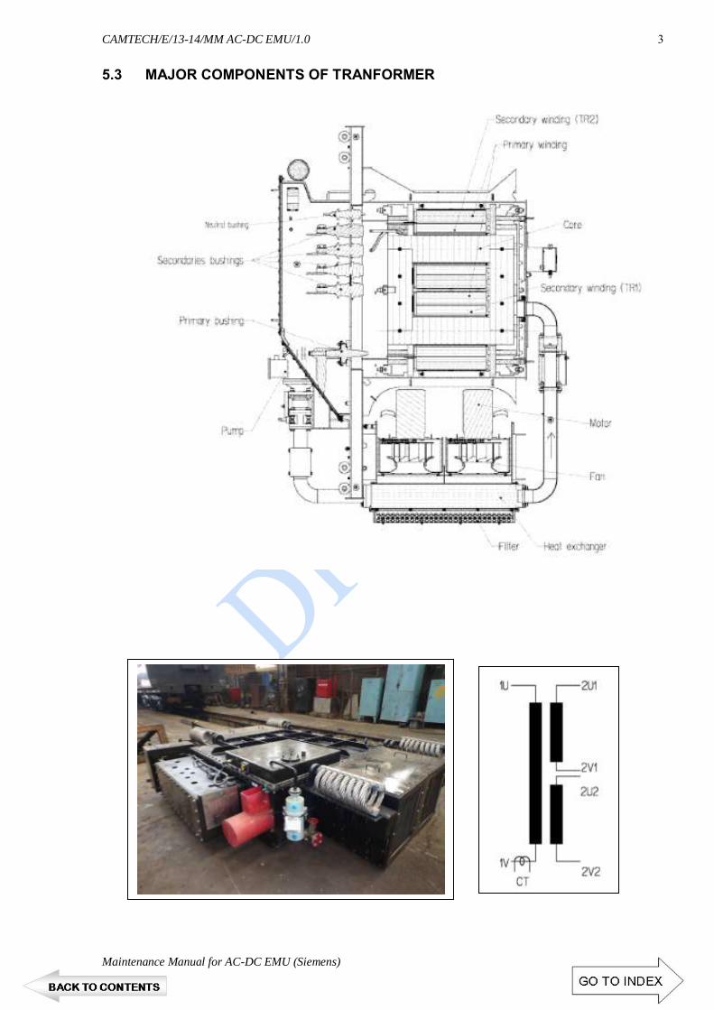
5.3.1 Transformer oil pump 04 5.3.2 Air Dryer (Breather) 04 5.3.3 Heat Exchanger (Radiator) 05 5.3.4 High Voltage Bushing ( HT terminal) 05 5.3.5 Earth Terminal 05 5.3.6 Butterfly Valves (Drain & Filling cock) 05 5.3.7 Ball valve 06 5.3.8 Marshaling Box (Low voltage terminal) 06 5.3.9 Name Plate 06 5.3.10 Suspension Arrangement 06 5.3.11 Bellow (Flexible Coupling) 07 5.3.12 Thermometer Sensor 07 5.3.13. Pressure Relief Valve 07 5.3.14 Oil Level Indicator 07
5.4 NEW OIL CHARACTERISTICS: 08 5.5 TRANSFORMER OIL COOLING CIRCUIT 09

CAMTECH/E/13-14/MM AC-DC EMU/1.0
Maintenance Manual for AC-DC EMU (Siemens) Chapter 5
1
CHAPTER 5
TRACTION TRANSFORMER
5.1 TRACTION TRANSFORMER
The transformer is designed for a nominal rating of 1250 kVA. It consists of a primary winding and 2 secondary windings. Therefore, 625 kVA is available at each secondary. This corresponds to a secondary side nominal current of 731 A at a secondary voltage of 855 Volt (22.5 kV mains voltage). The transformer is cooled with a total of 530 litres of oil.
5.2 TECHNICAL DATA
Manufacturer : ABB Secheron SA
Type : LOT1250, Oil Immersed transformer Identification No : XCH000000-AUC
Nominal Line Voltage : 25 kV (19 to 27.5 kV)
Line voltage min (2s < t < 10min) : 16.5 kV Line Voltage max (2s < t < 5 min) : 30 kV
Frequency : 50 Hz (46 to 54 Hz) Installation point : Under slung
Dimensions (length x width x height) : App. 2800 x 2000 x 850 mm Total weight, including oil : App. 3.3 t
Cooling : ODAF- mineral oil cooled Installation point : Under slung
Traction Transformer Fitted Under Slung

CAMTECH/E/13-14/MM AC-DC EMU/1.0
Chapter 5 Maintenance Manual for AC DC EMU (Siemens)
2
Technical data Primary Side Rated power : 1250 kVA Nominal primary Voltage : 22.5 kV
Rated current voltage : 58 A at 22.5 kV
Technical data Traction Winding Number : 2 Rated power : 625 kVA
Secondary Voltage : 855 V Standard current per winding : 731 A at 855 V (prim. 22.5 kV)
Leakage inductance : 1.465 mH 10% related to the secondary Transformation ratio : 26.32: 1 Resistance : 50 m - Related to secondary side
Magnetisation Current : 0.17 A ± 30% , Under 22.5 kV Efficiency : 96%
Cooling surface area : 4.37 m2 Turns Ratio : 26.294
Total Oil Volume at 20° C : 560 dm3
Winding Details
HV Winding Traction Winding
No of windings 1 2
Conductor Material Copper Copper
No of parallel conductors 1 per HV Coil associate to traction winding, 2 Coils
in parallel
2 on each traction winding
Total X-section 8.74 mm2 128.35 mm2
Rated current at 22.5 kV 55.55 A 731 A
Current Density 6.4 A/ mm2 5.69 A/ mm2
Number of layers 18 layer winding 6 layer winding
Winding Resistance (DC) at 85° C
9.135Ω 15.4 mΩ
No of Turns 2682 102
CAMTECH/E/13-14/MM AC-DC EMU/1.0
Maintenance Manual for AC-DC EMU (Siemens) Chapter 5
3
5.3 MAJOR COMPONENTS OF TRANFORMER

CAMTECH/E/13-14/MM AC-DC EMU/1.0
Chapter 5 Maintenance Manual for AC DC EMU (Siemens)
4
5.3.1 Transformer oil pump
Flow-well Oil Pump for transformer is glandless Mono-bloc Centrifugal type suitable for circulating the oil. The pump has inline suction and delivery flanges. The pump-set is driven by 3 Phase, 50 Hz, 415 V AC supply.
General specifications:
Motor H.P. 3 Discharge in LPM 700 Total Head in Meters 10.8 Mtrs (0.9 bar) Speed 2850 RPM Class of Insulation `H' Suction X Delivery 80 x 80 mm Total Weight 39 Kgs. Type 1530 Fabricant FLOWWELL PUMPS & METERS
5.3.2 Air Dryer (Breather)
The transformer is equipped
with two air driers. One is to dry the air in the oil expansion tank. The second one (smaller) is to dry the air in the bushing box.
The upper and lower parts of
air drier consist of compact casting in aluminium alloy and the transparent hose, which contains the salts (Silica-gel) and it is protected by a stainless steel cylinder drilled in such a way as to allow the visual control of salts.
The air sucked into the transformer (due to thermal contractions of oil mass) passes through these drier.
In the lower part there is a closing system which prevents the contact between air and salts. This closing system allows the air passage in the two directions (inlet and outlet) only when there is a pressure difference between the inside and the outside of the transformer.
Silica-gel air dries are transparent tanks of salts of silicon chemically pure, with cobalt indicator or without cobalt. Silicagel has the purpose to absorb the air humidity signaling the reached degree of saturation by change of colour:
With cobalt Without cobalt
BLUE = completely dry ORANGE = completely dry PINK = =completely saturated COLORLESS = completely saturated

CAMTECH/E/13-14/MM AC-DC EMU/1.0
Maintenance Manual for AC-DC EMU (Siemens) Chapter 5
5
The salts contained in the dehumidifier can be taken off and regenerated by heating them at 120-150°C until they get their original colour again. When more than the half of silicagel is became pink (or colorless) (water satured) it has to be fully changed or regenerated.
5.3.3 Heat Exchanger (Radiator)
The aim of the cooling system
is to transfer the electrical losses created within the transformer to the outside air. Two fans provide the necessary airflow to cool down the circulating oil through the cooler. The oil is pushed through the cooler by the circulating pump.
5.3.4 High Voltage Bushing ( HT terminal)
The main insulation of the
HV bushing, Elastimold 750 S, 18/30kV is a core of solid insulation with condenser layers for field control. The plug is particularly characterized by its space saving construction and simple assembly and disassembly.
The external cone of execution for the plug connection is
always protected by a cap when the plug is not attached. Before the HV plug is connected, the cone of bushing must
be cleaned. No foreign bodies may be gotten jammed. While the plug is connected, it should make certain that no air is included.
5.3.5 Earth Terminal
5.3.6 Butterfly Valves (Drain & Filling cock)
This valve is built with a aluminium casing. Sealing is realized with NBR gasket. The valve is equipped with a locking plate that indicated also the position (open or close). To operate the valve use a 19mm wrench. To lock the valve use M6 bolt or cadenas diameter 6 mm.

CAMTECH/E/13-14/MM AC-DC EMU/1.0
Chapter 5 Maintenance Manual for AC DC EMU (Siemens)
6
5.3.7 Ball valve
The ball valve is built in stainless steel with PTFE gasket. It is fixed by 4 screws M10 to the tank. The exit is closed by a 1"1/4 plug. The operating arm is fixed to the tank to insure the closed position
5.3.8 Marshaling Box (Low voltage terminal)
The connection box is IP67 box equipped with IP 68 cable gland. All electrical devices are connected in the connection box to terminal blocks.
ADO terminal block provided to avoid wire stripping and to have good safety and reliability. The main point for ABB terminal blocks are:
• Elimination of conductor preparation risks • No retightening • Vibration resistant • Corrosion resistant • A tool which guarantees a safe connection • Procedures simplification
5.3.9 Name Plate
5.3.10 Suspension Arrangement
The transformer is fixed under the coach body using rubber dampers. The rubber dampers are mounted to the transformer suspension arms by ABB Rubber dampers are chosen for their properties to limit the transmission of vibration from the transformer to the coach body and to absorb part of choc that coach body can transmit to the transformer. The arrangement also allows compensate flatness default,

CAMTECH/E/13-14/MM AC-DC EMU/1.0
Maintenance Manual for AC-DC EMU (Siemens) Chapter 5
7
5.3.11 Bellow (Flexible Coupling)
Bellow made from ductile metallic materials allows misalignment and thermal expansion of piping. The basic element, which is a thin-walled cylindrical tube, is formed into parallel corrugations with hydraulic or mechanical pressure.
The bellows are protected against object projection (stones etc.) with stainless plates placed in the exposed side around the bellows.
5.3.12 Thermometer Sensor
The thermometer sensor is composed of 2 platinum resistance thermometers PT100. The sensor is placed in oil. The thermometer sensor is used to measure the oil temperature in the transformer.
The sensor is screwed in a pocket,
and it is possible to change the sensor without oil draining. For a good heat transmission, the pocket is filled with oil. Enough space is keep free of oil to allow dilatation.
5.3.13. Pressure Relief Valve
The pressure relief valve (or over pressure valve) limit the pressure in the transformer tank. The valve open when the pressure over-pass 0.8 bar.
When the valve operates it causes a central
rod to protrude from the protective casing commuting immediately the switch and giving an electrical and visual signal. When the over-pressure falls down, a spring closes the valve. But the signal returns to its initial position only by manually pushing inwards.
5.3.14 Oil Level Indicator
The oil level indicator is located at the
expansion tank. The indicator shows the height of the oil level. The minimum and maximum Oil levels are displayed and also the oil level when the oil is 30°C.
The transformer is filled 100% with oil. The expansion of the oil is taken up by the expansion tank, which is connected to the transformer. The expansion tank is installed on the side of the transformer.
The min. mark is corresponding to an oil temperature of -20°C and max. mark is corresponding to an oil temperature of +120°C.

CAMTECH/E/13-14/MM AC-DC EMU/1.0
Chapter 5 Maintenance Manual for AC DC EMU (Siemens)
8
5.3.15 Oi1 level detector The oil level detector measures minimum level in the expansion
tank using floats. If the oil level becomes too low, the oil level detector switches and the transformer has to de-energized.
5.3.16 Oi1 flow sensor
The flow sensor detects a minimum oil flow. A paddle moves
related to flow volume and actuates a micro-switch.
5.4 NEW OIL CHARACTERISTICS:
Requested Value Typical Value
Density at 20° C 1.0 kg/dm3(Max) 0.876 kg/dm3
Kinematic Viscosity at 40 35 mm2/s (Max) 7.6 mm2/s
Flash Point Min 250° C 144° C
Pour Point Max -45° C -63° C
Water content Max 200 mg/kg < 20 mg/kg
Neutralisation Value Max 0.03 mg KOH/g < 0.01 mg KOH/g
Total Acidity Max 0.3 mg KOH/g 0.04 mg KOH/g
Total Sludge Max 0.05 %/mass < 0.02 %/mass
Break Down voltage Min 45 kV 40-60 kV >70 kv after treatment
Dissipation Factor at 90° C, 50 Hz Max 0.03 < 0.001
DC Resistivity at 90° C Min 2 G Ωm 5 G Ωm
Dissolved Gas Analysis
Sr. No Gas Limit value in ppm ( Max)
1 CO2 12000
2 CO 1000
3 H2 400
4 CH4 (Methane) 200
5 C2H6 (Ethane) 200
6 C2H4(Ethylene) 300
7 C2H2(Acetylene) 30

CAMTECH/E/13-14/MM AC-DC EMU/1.0
Maintenance Manual for AC-DC EMU (Siemens) Chapter 5
9
5.5 TRANSFORMER OIL COOLING CIRCUIT
Figure: Cooling circuit diagram
Cooling System: Make :
Type : Aluminium Plate Exchanger Oil Volume : 20 litre
Case : Steel Thermal data :
Air inlet Temperature : 50° C Air outlet Temperature: 77.7° C
Oil inlet Temperature : 85° C Oil outlet Temperature: 81.9° C
Oil flow : 655 lpm Fan Data: Numbers: 2 Type: Entry from Front, Exit to the bottom. Power consumption at rated capacity: 2 X 2.2 kVA (3.2 A) Motor Data: Make: ABB Type: HX100 LB1004/2 Voltage: 3 Phase, 415 V
Low Speed High Speed Starting Current/ Torque 450%/160% (4P) 600%/200% (2P) Continuous Rating 0.4 kW 1.6 kW Speed 1405 2825 Power Factor/ Slip 0.83/6.3% 0.92/5.8%
Transformer
Heat exchanger
Oil pump

CAMTECH/E/13-14/MM AC-DC EMU/1.0
Chapter 5 Maintenance Manual for AC DC EMU (Siemens)
10
Monitoring System
Equipment Type Make Limit
Pressure Relief Valve T3(DN80) Sukrut 0.8 bar
Thermometer sensor Double PT100 Altop
Oil Level Indicator Float arm Sukrut
Oil Level Detector Nivofix RW1016PVK Honsberg (EU)
Oil Flow Detector UB1025HM Honsberg (EU)
Current Transformer Siemens
Maintenance Check List: 1. DGA : As specified above 2. Winding Resistance :
HV Winding : 9.135Ω TR Winding : 15.4 mΩ 3. Insulation resistance :
Voltage Time Admissible Value at 20 ° C
1000V 30 seconds > 100 MΩ 60 seconds > 150 MΩ

CHAPTER 6
OTHER ELECTRICAL
EQUIPMENT

CONTENTS S.No. Description Page No. 6.1 DC HIGH SPEED CIRCUIT BREAKER UR 6 01 6.2 AC VACUUM CIRCUIT BREAKER (VCB) 02 6.3 AC-DC CHANGE OVER SWITCH 03 6.4 SURGE ARRESTER 04 6.5 DYNAMIC BRAKING RESISTER 05 6.6 EARTHING DIS-CONNECTOR AND SWITCH 06 6.7 BATTERY AND BATTERY CHARGER 07 6.8 MINIATURE CIRCUIT BREAKERS (MCBS) 08 6.9 SWITCHES 08 6.10 SOLENOID VALVE 08 6.11 SIGNAL BELL 08 6.12 CURRENT TRANSFORMERS 08 6.13 POTENTIAL TRANSFORMERS 09 6.14 VOLTAGE SENSING DEVICE 09 6.15 GOVERNERS 09 6.16 COMPRESSED-AIR UNIT 10 6.17 AUXILIARY AIR COMPRESSOR 10 6.18 MAIN AIR COMPRESSOR 10 6.19 PANTOGRAPH 11 6.20 TECHNICAL DETAILS 12

CAMTECH/E/13-14/MM AC-DC EMU/1.0
Maintenance Manual for AC-DC EMU (Siemens) Chapter 6
1
CHAPTER 6
OTHER ELECTRICAL EQUIPMENT
6.1 DC HIGH SPEED CIRCUIT BREAKER UR 6
The UR 6 circuit-breaker is a air cooled DC high-speed current-limiting circuit-
breaker. It has been designed to ensure a trip free, rapid opening of its main contact, on detection of a short circuit, and to quickly extinguish the arc by generating a constant over-voltage during the whole interruption process.
The circuit-breaker is made of independent mounted sub-assemblies,
corresponding to the different functions. 1. Fixed insulating frame made of glass-fibre reinforced insulating material. 2. Main circuit, consisting of a lower connection terminal, a moving contact, an
upper connection terminal, a fixed contact with horn (24) and another horn. 3. Over-current release. 4. Arc chute. 5. Closing device and fork. 6. Auxiliary contacts assembly.
Because of its short response time following the detection of an excess current
(short-circuit, over-load detection..), it is particularly suitable for the protection of the electrical equipment in rolling stock used on DC lines.
Make M/s Secheron
Type U6.32 Rated operational voltage 1800 V
Rated insulation voltage 2000 V

CAMTECH/E/13-14/MM AC-DC EMU/1.0
Chapter 6 Maintenance Manual for AC DC EMU (Siemens)
2
Rated operational current 1000 A
Conventional free air thermal current (at Temp. = 40°C) 1000 A Rated short-circuit breaking and making capacity Iss/T
Rated time constant T1 NA
Rated time constant T2 30 kA/15 ms
Rated time constant T3 30 kA/40 ms Rated time constant T4 30 kA/100 ms
Direct over-current release 0.45 - 0.9 kA 0.6 - 1.2 kA 0.9 - 1.8 kA 1.2 - 2.4 kA 1.5 - 3.2 kA
Maximum arc voltage 1.5 - 2.1 Ue
6.2 AC VACUUM CIRCUIT BREAKER (VCB) Technical Data
Make: M/s Autometers alliance Ltd Type: VCBA25.10Tr Maximum rated voltage 30kV Nominal rated voltage AC (1-Ø) 25kV Power frequency withstand voltage (dry & wet) 75 kVrms Lightning impulse withstand voltage 175 kVrms Rated current 1000Arms System frequency 50 Hz Short circuit rupturing capacity 16kArms (440MVA) Making current 40 kArms Short time current capacity 16 kArms(3 sec.) Opening time < 60 ms Closing time < 100 ms Control voltage 110 VDC Input air supply pressure 4.5 to 10 kg/cm² Rated operating sequence -- CO-3 min-CO

CAMTECH/E/13-14/MM AC-DC EMU/1.0
Maintenance Manual for AC-DC EMU (Siemens) Chapter 6
3
6.3 AC-DC CHANGE OVER SWITCH
The single-knife switch is designed to connect power supply from pantograph to other circuits provided in a traction vehicle.
This switch ensures switching between two different power supply units. The
switch is mounted on traction vehicle roof. The switch incorporates a moving contact knife fixed on an insulator and connected to a shaft which extends into a traction vehicle area and contact springs mounted on the base plate via insulator. Under the plate, fitted on the shaft is a lever designed to transfer the motion from a pneumatic cylinder, thus ensuring the moving contact knife turning.
There is a split on the shaft which controls via pin and adapter four auxiliary
contact switches. The base plate contains a bracket connected via pin to the pneumatic cylinder; a switchboard and a pneumatic electromagnetic valve 5/2 are used for the pneumatic cylinder control. Female panel connector mounted on the holder is connected to power leads for the electromagnetic valves and cam switches connected.
On the upper side, the plate is provided with an M8 thread for a bolt used for the
connection to a traction vehicle earthing system. Up to position of moving contact are supplied by power from pantograph:
- contact C with the pneumatic cylinder piston rod shifted out - contact B with the pneumatic cylinder piston rod slid in.
The switch is designed to switching power supply from the pantograph by
disengaging of moving contact (knife) from one contact spring, turning in approximately 60° and engaging into second contact springs.
Technical Data
Make: M/s Secheron Type: RS 25.10 Main circuit Nominal voltage UN 25 /kV/ AC Rated insulation voltage UNm 36 /kV/ AC Rated operating voltage Ue 27.5 /kV/ AC Frequency f 162/3; 50 or 60 /Hz/

CAMTECH/E/13-14/MM AC-DC EMU/1.0
Chapter 6 Maintenance Manual for AC DC EMU (Siemens)
4
Short-time withstand current: 1s Ik 25 /kArms/ Dynamic withstand current Ip 63 /kA/ Minimum conducting current (gold) 4mA/24V DC Breaking knife angle of turning ° 60° Mounting position horizontal Weight 57 kg Control circuit Nominal voltage 110 /V/ DC Tolerance of auxiliary voltage -30% / +25%
Pneumatic drive Operating pressure range 0.4 - 1 /MPa/ Dielectric test voltage: control circuit-earth (AC 50 Hz during 60 s) 1.5 /kV/ Change-over time (at pressure 1MPa) <3sec at
-30°C; +70°C Breaking capacity of the auxiliary contacts 1A/110V (L/R=5ms) Breaking knife angle of turning 60° Rated mechanical durability C3/A4 min. 250 000
operating cycles Inspection of the Contact Spring Force Contact springs: Contact pressure 20 to 40 N* Contact opening 10 mm * Force required for the knife to be drawn out of contact springs
6.4 SURGE ARRESTER
Surge arrester protects the insulation of high voltage and medium voltage devices against over-voltages which are caused by lightning or switching operations.

CAMTECH/E/13-14/MM AC-DC EMU/1.0
Maintenance Manual for AC-DC EMU (Siemens) Chapter 6
5
Surge arrester is constructed from serially connected, non-linear metal-oxide (MO) resistors. These MO resistors have an extremely non-linear resistance property. At the maximum operating voltage of Uc, only a small capacitive current will flow in the mA range. With an increase in voltage, the MO resistors enter a highly-conductive state practically without delay. Thus any further increase in voltage is limited to the specified residual voltage values.
After the decline of the overvoltage the arrester immediately turns back to the
non- or slightly-conductive state. The MO arrester converts the energy of the surge into heat, which it transfers to the surrounding air.
6.5 DYNAMIC BRAKING RESISTER
Technical Data Make Heine Gmbh
Type BWD73 Nominal Resistance (Rn) 3Ω + 7% -5%
Maximum Resistance Rmax 3.96 Ω (referred to 600°C) (Rn+ 7% + resistance rise due to
temperature rise) Minimum Resistance Rmin 2.85 Ω: (referred to 20°C)
Inductance: 7μH at 1 KHz Load Case-1 1600 kW (tb = 1s)
0 kW (tb =300 s) Load Case-2 1240 kW (tb = 2.5s)
0 kW (tb =120 s) Continuous Load 41 kW
Load Case 400 kJ (tb =100 ms) (Intermediate short circuit) 2X within 10 s
There after shut down. Creepage Distance ≥ 45 mm
Clearance Distance ≥ 18 mm Energy Absorption Capacity 2456 kJ
Resistance Material CrNi2521, Strip Material

CAMTECH/E/13-14/MM AC-DC EMU/1.0
Chapter 6 Maintenance Manual for AC DC EMU (Siemens)
6
6.6 EARTHING DIS-CONNECTOR AND SWITCH
This earthing disconnector is designed to earth the circuits on both sides, i.e. before and behind the main high-speed air switch in a traction vehicle. It is usually preceded by a control group switch with a reverse lever and a pantograph locking box.
The earthing disconnector ensures safety operation of a traction vehicle and safety
of staff members while performing the traction vehicle inspection and/or maintenance, and curing defects and/or making repairs.
On the plate face side is a control lever aimed at controlling the move of breaking
knife from one end position (Operation) to other end position (Grounded). Blocked mechanically in a groove, the lever must first be shifted out of the groove by pulling it towards oneself; only then it is possible to turn the lever counter-clockwise by 60°.
Mounted on the base plate back side, the switch has the fixed contact knives connected to a traction vehicle frame through a flexible bond when in the “Grounded” position. When in the “Grounded” position, the contact knives slides into the flexible contacts thus making ground connection.

CAMTECH/E/13-14/MM AC-DC EMU/1.0
Maintenance Manual for AC-DC EMU (Siemens) Chapter 6
7
6.7 BATTERY AND BATTERY CHARGER
Power supply 110V
The EMU features a 110 volt DC on-board supply system. The battery is located under the DTC and NDTC. The battery charger with 110 volt direct current is accommodated in the ACU. The battery charger in the ACU only charges the battery in the own basic unit.
The battery main switch is located in the shunting cab. This switch completely
isolates the battery from the on-board supply system. One switch per unit is provided. Before the battery can be switched ON via the electronics cabinet in the driver's cab, all battery main switches in the shunting cab must be switched ON. This is located in the cabinet below the shunting desk.
Figure: Battery main switch, shunting desk
The battery voltage is monitored by a minimum-voltage relay. When a specific voltage is reached, the driver can override it for the preparation of the unit via the "Isolated Under voltage" switch on the driver's cab.
In the case of a defective battery, the unit can continue to operate within the train
without any restrictions. This is ensured by a battery bus-bar which leads through the entire train.
The emergency light in the driver's cab is connected directly behind the battery
main switch. Therefore, it has to be ensured that the emergency light is switched OFF when parking the train (battery main switch is not switched OFF, vehicle is shut-down).

CAMTECH/E/13-14/MM AC-DC EMU/1.0
Chapter 6 Maintenance Manual for AC DC EMU (Siemens)
8
6.8 MINIATURE CIRCUIT BREAKERS (MCBS)
6.9 SWITCHES
6.10 SOLENOID VALVE 6.11 SIGNAL BELL
6.12 CURRENT TRANSFORMERS

CAMTECH/E/13-14/MM AC-DC EMU/1.0
Maintenance Manual for AC-DC EMU (Siemens) Chapter 6
9
6.13 POTENTIAL TRANSFORMERS 6.14 VOLTAGE SENSING DEVICE
Technical Details Make : Birkholz Type : HK1.1A Direct voltage : 1 000 V -- 4 000 V Alternating Voltage : 25 kV 50 Hz (17 000 V -- 30 000 V)
Sr.No Type of signal Output 1 Filtered AC for more than 180 ms at AC Evaluation Unit AC 2 DC Current more than 5 mA at DC evaluation Unit DC
6.15 GOVERNERS
Sr. No
Governor Make Type Setting
1 Main Compressor Governor
Moller MCS-11-SOND910-G Set: 6.0 ksc Trip: 7.0 ksc
2 Auxiliary Governor
Moller SMC
MCS-11-SOND910-G ISG120-031-W
Set: 5.3 ksc Trip: 6.3 ksc
3 Equipment Governor
Moller SMC
MCS-11-SOND910-G ISG120-031-W
Set: 5.6 ksc Trip: 4.6 ksc
4 Control Circuit Governor
Moller SMC
MCS-11-SOND910-G ISG120-031-W
Set: 4.0 ksc Trip: 3.2 ksc
5 Parking Brake Governor
Indfos Denfos
116X Set: 3.0 ksc Trip: 2.0 ksc

CAMTECH/E/13-14/MM AC-DC EMU/1.0
Chapter 6 Maintenance Manual for AC DC EMU (Siemens)
10
6.16 COMPRESSED-AIR UNIT
The compressed-air unit consists mainly of two compressed-air circuits, which are connected to each other by means of a non-return valve. The pantograph, AC main circuit-breaker and the voltage change-over switch are located in one of the compressed-air circuits (auxiliary air circuit).
In normal operation, the other compressed-air circuit (main air circuit) supplies
the auxiliary air circuit with compressed air via the non-return valve, the compressed-air brake and parking brake system, the air suspension, pneumatic horn and windscreen wipers.
6.17 AUXILIARY AIR COMPRESSOR
The auxiliary air compressor is located in the HTC and generates the compressed air required for the operation of the components in the auxiliary air circuit if the pressure from the main air circuit is not available. This is often the case when the motorised train is being prepared.
The auxiliary air compressor is
supplied directly by the battery. 6.18 MAIN AIR COMPRESSOR
A three-phase piston air compressor installed underneath the DTC / NDTC supplies the train with compressed air. It is automatically activated at a pressure of 6.0 bar and deactivated at a pressure of 7.0 bar. The starting takes place without any pressure.
The compressed air is lead to several air reservoirs via a non-return valve and an air drying system with automatic drainage. The air reservoirs are also equipped with automatic drainage.
One main air compressor is provided for each unit. All vehicles are equipped with a continuous MRP (Main Reservoir Pipe).
In addition, several compressed-air reservoirs for the brake, the spring-loaded brake, the air suspension and the horn are provided.
Auxiliary Air Compressor
Main Air Compressor fitted under slung

CAMTECH/E/13-14/MM AC-DC EMU/1.0
Maintenance Manual for AC-DC EMU (Siemens) Chapter 6
11
The compressed-air system is protected by a safety valve. This safety valve
triggers when a pressure of 7.8 bar is exceeded.
The motor compressor set consists of the following main assemblies:
Three-phase motor, compressor, resilient mounting and dry-type air filter. The resilient mounting is available in the form of rubber shocks, spring wire shocks and a combination of rubber and spring wire shocks. The compressor has rubber shocks, the motor is equipped with spring wire shocks.
Technical Details of Motor Compressor Set
Compressor
Make : Knorr- Bremse Type : VV120 Three cylinder reciprocating Low Pressure Stage : 2 nos. Dia 95 mm High Pressure Stage : 1 no. Dia 75 mm Stroke : 60 mm Lubrication : Oil Flash type Oil Consumption : < 1 c.c. / operating hour Cooling : inter cooler and after cooler Oil capacity (Max/ Min) : 3.7 l/ 1.7 l Max outlet pressure : 10 bar Allowed duty cycle : 30-100% Motor Make : Knorr- Bremse Type : KB/18-132MB Voltage : 415V

CAMTECH/E/13-14/MM AC-DC EMU/1.0
Chapter 6 Maintenance Manual for AC DC EMU (Siemens)
12
6.19 PANTOGRAPH
It is provided to collect H.T. Supply from OHE contact wire. The OHE supply may be 1500 VDC or 25 KV AC, 50Hz. This is fitted on foot insulator on the top of the roof of the motor coach. The pantograph is mounted on the roof with supporting insulators. The lightning arresters on the roof protect the unit from hazardous over voltage surges. The current is guided via the transformer in AC operation mode or directly to the current converter in DC operation mode.
6.20 TECHNICAL DETAILS
Sr.No. Item M/s Shunk M/s SIL
1 Standard UIC 60494-1
2 Type WBL 23.03 AM-18 B2
3 Min. Height with Insulators 575±10 mm 575±10 mm
4 Insulation Distance 250 mm 250 mm
5 Max Height in raised position Max. 2290 mm Max. 2290 mm
6 Maximum Extension Max. 2400 mm Max. 2400 mm
7 Operating Range 500-2000 mm 500-2000 mm
8 Width of pan head 1-17110.11856 2032 mm 2032 mm
9 Total length in resting position 2370±10 mm 2370±10 mm

CAMTECH/E/13-14/MM AC-DC EMU/1.0
Maintenance Manual for AC-DC EMU (Siemens) Chapter 6
13
Sr.No. Item M/s Shunk M/s SIL
10 Total weight including insulators ≈ 150 kg ≈ 290 kg
11 Current collecting strips spacing 250 ± 10 mm 250 ± 10 mm
12 Current collector - material Electrolyte copper Electrolyte copper
13 Pan base sheet thickness Old- 1.6 mm
Mod.- 2.0 mm
2.0 mm
14 Nominal Voltage 25kV AC/
1.5 kV DC
25kV AC /
1.5 kV DC
15 Nominal current 60A/1100 A
16 Maximum speed under good OHE 160 kmph 160 kmph
17 Ambient Temperature -10° C to 50° C -10° C to 50° C
18 Propulsion system Air bellow Servo motor
19 Air pressure for continuous operation
7.0 bar 7 bar (5<b<10 ksc)
20 Contact Pressure 11.5 (11- 14 kg
recommended)
11.5 kg ( 12 kg
recommended)
21 Raising time to maximum working height
10 second 0 m to 1.5 m in 6-10 s
22 Lowering time from maximum working height
10 second 1.5 m to 0 m in 10 s


CHAPTER 7
CONTROL SYSTEM
(SIBAS 32)

CONTENTS
S.No. Description Page No. 7.1 CONTROL TECHNOLOGY 01 7.2 TRACTION CONTROLS 01 7.3 BRAKE CONTROL 03 7.4 AUTOMATIC VIGILANCE DEVICE 03 7.5 DISPLAY SUPPORT 03
7.5.1 General View of MMI (Man-Machine Interface) 04 7.5.2 Different MMI Screens. 05
7.6 MAIN TASKS OF THE TCU 09 7.6.1 Internal Structure and Method of Operation of the TCU 10 7.6.2 MVB-Communication 10 7.6.3 Higher-level Traction Functions 10 7.6.4 Control of the traction converters 10
7.7 SIBAS 32 SYSTEM 11 7.7.1 View of a SIBAS-KLIP substation 11

CAMTECH/E/13-14/MM AC-DC EMU/1.0
Maintenance Manual for AC-DC EMU (Siemens) Chapter 7
1
CHAPTER 7
CONTROL SYSTEM (SIBAS 32)
The main components of control system (SIBAS 32) are as under:
i. CCU (Central Control Unit)
ii. TCU (Traction Control Unit) iii. BCU (Brake Control Unit)
iv. MMI (Man Machine Interface) v. MVB (Multi Vehicle Bus)
vi. SKS (SIBAS Klip Station)
7.1 CONTROL TECHNOLOGY
The control technology was designed redundantly for this vehicle. At the heart of each train, there are two central control units called CCU. These are located in the driver's cab. Apart from the control of the entire train, the CCU also controls the display.
The vehicles of one unit and the units themselves are connected to each other via
an MVB (Multi Vehicle Bus). The MVB is designed redundantly with line A and line B. If the MVB is not available despite of this fallback, the vehicle can be operated in degraded operation via the rescue drive mode (RDM). This function is only used for clearing the track. In this operating mode, the display is switched off and the auxiliary tell-tale lamps are switched on.
All switches, buttons and consumers which are controlled via the control
technology are connected to a KLIP station. The KLIP stations are distributed Input/ Output stations for the CCU. They are used to significantly reduce the length of the control lines to the CCU.
7.2 TRACTION CONTROLS
This vehicle is a three-phase vehicle which is controlled via a TCU. The TCU processes the propulsion and braking commands (electronic brake) and transmits this information to the current converter. If there is a TCU failure, the unit in question can no longer operate autonomously. This does not pose a risk if the unit is part of a train, as there may be at least one basic unit failure per train.

CAMTECH/E/13-14/MM AC-DC EMU/1.0
Chapter 7 Maintenance Manual for AC DC EMU (Siemens)
2
Figure 8.1: Overview of control technology / MVB bus

CAMTECH/E/13-14/MM AC-DC EMU/1.0
Maintenance Manual for AC-DC EMU (Siemens) Chapter 7
3
7.3 BRAKE CONTROL
All parts which affect the brake directly, except for the driver's automatic brake valve in the driver's cab, are connected to the MVB bus. The brake commands from the joystick/brake lever are thus transmitted to the CCU. The CCU calculates the brake forces for the EP and the ED brake and transmits the value to the BCUs and TCUs. The EP unit converts the brake value generated by the current into compressed air.
A pneumatic WSP (Wheel Slip Protection) is not available in this vehicle
(sliding/skidding protection is only available for the driven axles in the motor car). This means that the driver must brake earlier if the rails are slippery in order to avoid wheel flats.
In the case of a brake malfunction, the driver can always stop the train by moving
the joystick/brake lever into the emergency brake application position. Furthermore, the function of the driver's automatic brake valve can be used as a fallback at any time.
If there is BCU failure or defect, the TCU takes over all of the functions.
7.4 AUTOMATIC VIGILANCE DEVICE
The automatic vigilance device has been implemented via the master controller. If the driver releases the vigilance monitoring button during the journey, the brakes are applied automatically and the power of the train is switched off. This only happens during the journey. If the speed is below 5km/h, this function is disabled.
In rescue drive mode, the automatic application of the brakes is immediately initiated even if the vigilance monitoring switch is not actuated and if the speed is below 5km/h.
7.5 DISPLAY SUPPORT
The MMI (Man-Machine Interface) is installed in the driver's cab in the DTC and informs the driver of the current state of all important functions in the train. The states of a function are indicated to the driver by means of coloured icons. The driver can detect faults at one glance. The display assists the driver during the subsequent error detection. For information on further actions, the driver can call up the corresponding remedy for the error message.

CAMTECH/E/13-14/MM AC-DC EMU/1.0
Chapter 7 Maintenance Manual for AC DC EMU (Siemens)
4
7.5.1 General View of MMI (Man-Machine Interface)
1 Display ON / OFF
2 Not Connected
3 Legends of Symbols (Meaning)
4 Event Overview
5 Trouble Shooting Guidelines for Motorman
6 Not Connected
7 Brightness Control Dialog
8 Not Connected
9 Not Connected
10 Clear
11 Cursor Up
12 Cursor Down
13 Curser Left
14 Curser Right
15 Enter
16 to 25 Soft keys 0 to 9
Figure 8.2: Man Machine Interface (General View)

CAMTECH/E/13-14/MM AC-DC EMU/1.0
Maintenance Manual for AC-DC EMU (Siemens) Chapter 7
5
7.5.2 Different MMI Screens. A. Top level screen
B. Unit Screen
1 Train No. Not commissioned 2 Screen designation 3 Date 4 Time 5 Main screen 6 Massage text 7 Short massage 8 Soft keys 9 Short massage
Figure 8.3: Top level screen
Figure 8.4: Unit Screen

CAMTECH/E/13-14/MM AC-DC EMU/1.0
Chapter 7 Maintenance Manual for AC DC EMU (Siemens)
6
C. Driver / Brake Screen showing percentage traction / Braking
D. Legend of Indications (By pressing ‘i’)
Figure 8.5: Driver / Brake Screen showing percentage traction / Braking
Figure 8.6: Legend of Indications (By pressing ‘i’)

CAMTECH/E/13-14/MM AC-DC EMU/1.0
Maintenance Manual for AC-DC EMU (Siemens) Chapter 7
7
E. Legend of Indications (By pressing ‘i’ & 2)
Figure 8.7: Legend of Indications (By pressing ‘i’ & 2)

CAMTECH/E/13-14/MM AC-DC EMU/1.0
Chapter 7 Maintenance Manual for AC DC EMU (Siemens)
8
F. Legend of Indications (By pressing ‘i’ & 3)
Figure 8.8: Legend of Indications (By pressing ‘i’ & 3)

CAMTECH/E/13-14/MM AC-DC EMU/1.0
Maintenance Manual for AC-DC EMU (Siemens) Chapter 7
9
G. Legend of Indications (By pressing ‘i’ & 4)
7.6 MAIN TASKS OF THE TCU
The Train Control Unit (TCU) of the SIBAS 32 S system is used for processing, evaluating, storing and transferring data and signals in electric rail vehicles. The main tasks of the TCU for the EMU are listed as follows: Data exchange via the MVB-Communication Module with the other Basic Units of
the train set. Data exchange via the MVB with ACU, BCU, KLIP etc. of the own 3-car-basic-unit Control of power switches Control of the defined tractive and regenerative braking effort Generation of control signals for the traction converters Monitoring (power switches, current, voltage, temperatures etc.) Diagnostics
These tasks are fulfilled by TCU via hardware and software components inside the TCU.
1 PIS MMI
2 Train radio hands-free module
3 Train Radio MMI
4 Pressure Gauge Parking Brakes
5 Train radio Handset
Figure 8.9: Legend of Indications (By pressing ‘i’ & 4)

CAMTECH/E/13-14/MM AC-DC EMU/1.0
Chapter 7 Maintenance Manual for AC DC EMU (Siemens)
10
7.6.1 Internal Structure and Method of Operation of the TCU
The TCU consists of a combination of electronic devices in a forced-air cooled rack. The connection to the vehicle environment is implemented by front plugs.
The TCU SIBAS 32 S of the EMU vehicle consists of a Central Processing Unit
(CPU) and three lower-level sub-computers (signal processors). The CPU fulfils the Higher-level Traction Functions.
The three signal processors implement the Control of the traction converters
itself. There are two signal processors for the two Pulse Width Modulated Inverters (PWMI) and one signal processor for the two Four Quadrant Choppers (4QC).
7.6.2 MVB-Communication
With the help of the MVB-Communication Module (located on the CPU-card) the CPU exchanges relevant signals with the other MVB stations of the own Basic Unit (like BCU, ACU, KLIP, etc.). Also the communication with the other 3-car units in the train set is realized with the MVB-Communication Module.
7.6.3 Higher-level Traction Functions
The central processing unit (CPU) also controls the higher-level functions of the traction system. In response to the driver’s controls (e.g. driving set point) the CPU determines the required power flows and thus generates set points for the two 4QC (not operated in DC-mode) and the two PWMIs. The CPU enables closure of the main circuit breakers and controls the state of various internal breakers and also wired train lines.
Therefore the CPU is able to input and output binary Signals via the internal bus
with the help of Binary Input/ Output Devices. The CPU provides monitoring and protection functions to detect faults in the system. When a fault is detected appropriate action is taken to ensure the system remains safe and to limit consequential damage.
Diagnostic information is provided to the train driver and to maintenance staff.
With the help of a Service PC and a special software tool (SIBAS Customer Monitor) the diagnostic information of the TCU diagnosis memory can be read out and further maintenance tasks can be fulfilled.
7.6.4 Control of the traction converters
Each of the signal processors implements the software control algorithm required to generate the power semiconductor firing pulses in response to the set point values from the central processing unit. Because the signal processors perform all time-critical functions of the traction closed-loop control and converter open loop control, the CPU is relieved of computationally intensive tasks.
Each of the signal processors interacts with special interface devices e.g. in order
to actuate the power semiconductors and to read in actual drive values like voltages, currents, temperatures etc.

CAMTECH/E/13-14/MM AC-DC EMU/1.0
Maintenance Manual for AC-DC EMU (Siemens) Chapter 7
11
7.7 SIBAS 32 SYSTEM (SIEMENS RAILWAY AUTOMATION SYSTEM WITH 32 BIT MICRO-PROCESSOR)
The SIBAS 32 system (Siemens Railway Automation System with 32 bit
microprocessor) is employed for modulating and logic control functions in mass transit rolling stock such as light rail vehicles (trams), underground railways, suburban rapid transit vehicles and trolley buses, as well as in long-distance vehicles, for example, high-performance locomotives, high-speed trains diesel-electric locomotives.
The system controls, monitors and protects the vehicle drive in the area of the
converter equipment and performs the information processing in a control level embracing the whole vehicle as the central control unit.
The recording and control of digital and analog process signals "locally" at the
vehicle control is realized using SIBAS-KLIP. SIBAS-KLIP comes from the German for "intelligent terminal for peripheral
interfacing". The peripheral signals in the vehicle are hereby connected to the I/O module of
the SIBAS-KLIP substation (SKS) by means of front connectors and are connected to the multifunction vehicle bus (MVB) through the AS 318 MVB interface via the vehicle control.
7.7.1 View of a SIBAS-KLIP substation
The following picture shows two SIBAS-KLIP substations arranged above one another:


CHAPTER 8
BOGIE & UNDER GEAR

CONTENTS S.No. Description Page No. 8.1 INTRODUCTION 01 8.2 BOGIE FRAME 01 (Ref: CMI- K001) 8.3 WHEEL & AXLE 02 8.4 ROLLER BEARINGS 03 8.5 AXLE BOX HOUSING 04 8.6 AXLE BOX SPRINGS 04 8.7 LOWER SPRING SEAT 04 8.8 DASHPOTS AND AXLE GUIDE ASSEMBLIES 05 8.9 BOLSTER AND BOLSTER SPRING 05 8.10 HYDRAULIC SHOCK ABSORBERS 05 8.11 RUBBING PLATE IN MC AND HCC BOGIE 06 8.12 EQUALISING STAYS 07 8.13 CENTRE PIVOT (MC & HCC bogie) 08 8.14 CENTRE PIVOT (Trailer Coach) 09 8.15 SIDE BEARERS 10 8.16 ANCHOR LINKS (Trailer bogies) 11 8.17 HANGER AND HANGER BLOCKS 11 8.18 BOGIE BRAKE GEAR 12 8.19 BUFFING & DRAW GEAR 13

CAMTECH/E/13-14/MM AC-DC EMU/1.0
Maintenance Manual for AC-DC EMU (Siemens) Chapter 8
1
CHAPTER 8
BOGIE & UNDER GEARS
8.1 INTRODUCTION
The bogie frame is a welded construction with two longitudinal girders and a cross bar and two frame ends. The tractive or brake force is transmitted via a bogie pin from the bogie to the body.
The frame ends are used to take up the brake cylinder and the brake rigging. This
vehicle features tread brakes, which have a direct effect on the wheel.
Furthermore, 4 steel cables are each located between body and bogie. These are used as a lifting supports.
For primary suspension, buffer height, brake rigging, wheel and axle, hydraulic shock absorbers of AC EMU, DC EMU, AC-DC EMU bogie refer CMI – K001 (April 2000) and amendment slip no.1(Feb. 2007) and for maintenance of air suspension refer CMI-9802 (Rev.2) , February 2008 issued by Carriage Directorate, RDSO, Lucknow .
8.2 BOGIE FRAME
(Ref: CMI- K001)
Bogies of motor coaches (MC), high carrying capacity coaches (HCC) and trailer coaches (TC) are of all welded, light weight construction. The axles, with self aligning roller bearings mounted inside cast steel axle boxes, are rigidly guided by telescopic dash pot and axle box guide assemblies.
Helical springs working in parallel with dashpots are used for primary suspension.
Coach body is supported on two side bearers located 1700 mm (TC) and 1200 mm (MC & HCC) apart on a floating bogie bolster which in turn rests on air spring supported on a spring plank hung on swing links from bogie frame. The air springs at each end of bolster are damped by hydraulic shock absorbers. Side bearers consist of metal slides immersed in oil baths well protected from dust ingress.
Primary springs
Secondary air suspension Lifting support

CAMTECH/E/13-14/MM AC-DC EMU/1.0
Chapter 8 Maintenance Manual for AC DC EMU (Siemens)
2
Refer drawing no. ICF/MRVC/M-0-0-001 (sheet 1 & 2), AC/DC EMU/D2-0-0-201 (sheet 1 & 2) and AC/DC EMU/C2-0-0-201 (sheet 1 & 2) for bogie general arrangement of motor coach, D coach and C coach respectively given in Annexure for drawings.
Refer drawing no. ICF/MRVC/M-0-3-001 (sheet 1 & 2) and ICF/MRVC/D-0-3-
001 (sheet 1 & 2) for bogie frame arrangement of motor coach and D/C coach respectively given in Annexure for drawings.
No weight is transferred through the bogie (center) pivot, which is located in the
centre of the bolster. The pivot acts merely as a centre of rotation and serves to transmit acceleration and retardation forces.
The floating bolster in TC bogie is secured in the longitudinal direction to bogie
frame by means of two anchor links with silent block bushes, located diagonally opposite to each other and transmit draw and braking forces between bogie frame and coach body through the centre pivot. The MC & HCC bogie bolster is located between bogie transoms and transmits draw and braking forces through rubbing plates fixed at the bolster ends.
8.3 WHEEL & AXLE
The EMU coaches are provided with composite design of wheels consisting of rolled steel wheel centres with renewable tyres. The tyres of TC bogies are fastened to the wheel disc with glut rings whereas the MC/ HCC bogies have, in addition to the glut rings, 4 locking keys to ensure more positive securing.
Refer drawing no. ICF/MRVC/M-0-2-001 for axle and wheel set given in Annexure for drawings.

CAMTECH/E/13-14/MM AC-DC EMU/1.0
Maintenance Manual for AC-DC EMU (Siemens) Chapter 8
3
Tyre Profile
1. The new/re-turned tyre profile shall be as per ROSO Sketch No. 91146 atl. 2.
2. The condemning limits for the flange wear, root wear, deep flange, sharp flange, hollow
tread wear and flat surface on tyre shall be as per the condemning gauge shown in plate 45 of I.R.CA Part IV.
3. Wheel gauge should be within the tolerance of +2/-1 mm.
Wheel Diameter
Bogie New Condemning Last Shop Issue Size 1. MC 952mm 877mm 885mm 2. TC 952mm 857mm 865mm 3. HCC 952 mm 865mm 873mm
Permissible Variation on Wheel Tread Diameter
The permissible variation in tread diameter of wheels at the time of tyre turning or wheel
replacement are as follows:
1. Wheels of the same axle : 0.5mm
2. Wheels of the same bogie : 5.0mm
3. Wheels between two bogies under the same coach : 13.0 mm
No separate service limits are specified as the above figures have been fixed to allow for the differential wear likely to develop between successive tyre turnings/ wheel changing. It is, therefore, not necessary to withdraw EMU/MEMU stock from service specifically for restoring the differential between wheel diameters to be within the prescribed limits.
Material Specification for Wheel and Axle
The material specification applicable to the wheels and tyres are as follows:
1. Tyres : IRS Specification R-15/95. 2. Axle
: IRS Specification R-16/95 for TC bogies
IRS Specification R-43/92 for MC & HCC bogies 8.4 ROLLER BEARINGS
MC & HCC Bogies are fitted with direct mounted, double row, self aligning roller bearings No. 22328 C/C3. TC Bogies are fitted with direct mounted, double row, self aligning roller bearing No. 22326 C/C3.
Refer drawing no. EMU/M-0-2-016 (sheet 1 & 2) and EMU/M-0-0-001 (sheet 1
& 2) for roller bearing of motor coach, D coach/C coach respectively given in Annexure for drawings.

CAMTECH/E/13-14/MM AC-DC EMU/1.0
Chapter 8 Maintenance Manual for AC DC EMU (Siemens)
4
8.5 AXLE BOX HOUSING
Double row self-aligning spherical roller bearings are housed in accurately machined cast steel axle boxes. The axle boxes are also provided with light alloy front and back covers secured by four bolts.
Refer drawing no. ICF/MRVC/M-0-2-002 (sheet 1 & 2) for axle roller bearing
housing and gear-wheel assembly of motor coach given in Annexure for drawings.
Axle boxes and covers should be thoroughly cleaned and checked for cracks particularly at the holes of the covers which have shown proneness to failures. The bolts should be examined for worn threads, straightness, etc. before re-use and should be well tightened and locked by spring washers and split pins to ensure that the covers and the axle box housing form a water tight assembly and protect bearing from dust and moisture.
8.6 AXLE BOX SPRINGS
Axle box springs are of helical type manufactured from centreless ground chrome vanadium, silica manganese steel. These springs are also shot-peened to obtain higher fatigue life. It is necessary to check these springs for cracks and measure their free height to ensure that they meet the design requirements.
All springs shall be grouped in three categories and used on bogies as per instructions detailed in RDSO Technical Pamphlet No.C-8419 (Rev 1).
8.7 LOWER SPRING SEAT
Lower spring seat on the axle box wing in which guide bush of dashpot moves up and down does not normally wear in service. In the absence of inadequate quantity of oil in the dashpot. the inside surface is likely to wear. If the surface is worn more than 0.4 mm in diameter or if the surface is scored or otherwise damaged, the lower spring seat should be reclaimed.
All lower spring seats should be carefully checked for cracks before reuse.

CAMTECH/E/13-14/MM AC-DC EMU/1.0
Maintenance Manual for AC-DC EMU (Siemens) Chapter 8
5
8.8 DASHPOTS AND AXLE GUIDE ASSEMBLIES
Axle box guides are accurately machined hollow forgings welded to the bogie frame to ensure that the wheel sets are rigidly guided in parallel. These guides are fitted with acetal/ bronze bush at the lower end for close guidance of the wheel set both in lateral and longitudinal directions. The lower spring seat is filled with oil and the assemblies sealed with rubber ring to make it oil tight.
The provision for topping-up oil in the dashpot of MC & HCC bogie are made. In
the trailer coach bogies, holes on the bogie side frame above each guide are provided to top up the damping fluid when required.
Refer drawing no. AC/DC EMU/M2 -0-1-201 for axle box guide given in
Annexure for drawings. 8.9 BOLSTER AND BOLSTER SPRING
Bolster rested on both ends on air springs as shown below. More details are given in chapter on ”Suspension”.
Refer drawing no. ICF/MRVC/M-0-4-001 (sheet 1 & 2) and DMU/DPC/10-0—4-001 (sheet 1 & 2) for bogie bolster arrangement of motor coach, D coach/C coach respectively given in Annexure for drawings.
8.10 HYDRAULIC SHOCK ABSORBERS
The hydraulic shock absorbers are fitted to work in parallel with bolster springs. These shock absorbers normally give trouble-free service and require no attention in between POHs. However, shock absorbers which are found either leaking or physically damaged should be replaced.

CAMTECH/E/13-14/MM AC-DC EMU/1.0
Chapter 8 Maintenance Manual for AC DC EMU (Siemens)
6
As the resistance of these shock absorbers is likely to deteriorate in service, it is necessary to attend to them as per instructions given in the manufacturer's maintenance manual.
8.11 RUBBING PLATE IN MC AND HCC BOGIE
Nylon rubbing plate has been fitted to the bolster which serves as cushion between the bolster and bogie frame. Initial clearance of 1mm on each side has been provided between the nylon rubbing plate and steel rubbing plate.
During POH,' this clearance must be maintained by fitting steel packings of
suitable thickness. During service, this clearance should not exceed 3mm on each side. Any higher clearance may cause excessive longitudinal oscillations and may strain stay tubes (connecting the bolster to the spring plank) and cause their breakage.
Vertical and Horizontal Shock Absorbers

CAMTECH/E/13-14/MM AC-DC EMU/1.0
Maintenance Manual for AC-DC EMU (Siemens) Chapter 8
7
8.12 EQUALISING STAYS
Equalising stays connecting the spring plank and bolster, pin jointed at both ends, have been provided to prevent lateral thrust on bolster springs. It is necessary to remove the pins at every POH, clean and oil them to ensure that they are free to rotate when re-assembled.
Any restricted movement at these joints is likely to prevent free movement of
bolster. The free movement of pins can be ensured by greasing the assembly.
The pins should be provided with washers and split pins to ensure that they do not fall out in service.
Figures given for Equalising stays of MC / HCC and TC bogies:

CAMTECH/E/13-14/MM AC-DC EMU/1.0
Chapter 8 Maintenance Manual for AC DC EMU (Siemens)
8
8.13 CENTRE PIVOT (MC & HCC bogie)
The centre pivot arrangement is shown in Fig. given below. The body bolster of the under-frame is provided with a bush of inner dia 90mm in the top and 150mm dia hole at the bottom and the centre pivot pin, when fitted to the body bolster, perfectly fits into these holes as shown in diagram given below.
Any wear due to bogie rotation is taken up by the upper and the lower bushes
between the centre pivot pin and the bogie bolster.

CAMTECH/E/13-14/MM AC-DC EMU/1.0
Maintenance Manual for AC-DC EMU (Siemens) Chapter 8
9
8.14 CENTRE PIVOT (Trailer Coach)
The centre pivot arrangement is shown below. It is not designed to transmit any vertical load but transmits only tractive and braking forces.

CAMTECH/E/13-14/MM AC-DC EMU/1.0
Chapter 8 Maintenance Manual for AC DC EMU (Siemens)
10
8.15 SIDE BEARERS
Side bearers consist of a hard wearing ground steel plate immersed in an oil bath with a floating bronze wearing piece, which has a self aligning spherical top surface on which the body rests and transmits the vertical load. The oil well is provided with a cover to prevent ingress of dust.
The hard ground plate and the spherical bronze wearing piece are likely to wear in
service. The hard ground plate should be renewed when the wear exceeds 1.5mm or ridges are observed on the plate. The bronze wearing piece should be renewed when the wear on the mating surface reaches 3 mm or damages occur to the oil grooves. Sharp edges which are known to develop at the periphery of the wearing pieces are likely to impair lubrication and should be rounded off before re-using.
For filling up oil in side bearer without lifting the coach, oil filling nipples have
been provided on the oil well.
Any of the following oils can be used for the side bearers and the quantity required per side bearer is 2.5 litres.
IOC : Servoline-68 HPC : Yantrol-68 BPC : Bharat Univol-68

CAMTECH/E/13-14/MM AC-DC EMU/1.0
Maintenance Manual for AC-DC EMU (Siemens) Chapter 8
11
8.16 ANCHOR LINKS (Trailer bogies)
Anchor links should be carefully examined for cracks at the weld. The rubber in the silent bloc should also be carefully examined for deterioration. Appearance of fretting on the edges of the rubber is an indication of deterioration of rubber.
Whenever a silent bloc is to be replaced, it must be from those that have been
duly tested. To avoid pre-loading of the anchor link while assembling on the bogie, ensure that the assembly can be done without forcing the link into position. This can be done conveniently after lowering the body on the bogies.
8.17 HANGER AND HANGER BLOCKS
Hanger and hanger blocks shown in Fig. given below should be thoroughly cleaned after dismantling and examined carefully for cracks /wear and other damages.

CAMTECH/E/13-14/MM AC-DC EMU/1.0
Chapter 8 Maintenance Manual for AC DC EMU (Siemens)
12
The extent of permissible wear on these components is indicated below: (Ref: CMI - K001)
Trailer bogie
Components Size New Condemning Wear Shop issue size
Hanger block 8 6.5 1.5 7.00 Pin 45 43.5 1.5 44 Hanger 354 357 3 355.5
Motor bogie Components Size New Condemning Wear Shop issue
size Hanger block 9.5 8 1.5 8.5 Pin 45 43.5 1.5 44 Hanger 246 249 3 247.5
8.18 BOGIE BRAKE GEAR
Maximum radial clearance of 1 mm between the brake gear pins and bushes is permitted. If the clearance is more, the worn out part should be replaced and the standard clearance to be maintained.
Brake block should be replaced when they wear out to thickness of 16 mm by
removing the looped key from the brake head. An adjusting palm pull rod with holes displaced at regular intervals is provided in
the brake rigging to take up slack in rigging due to tyre wear. Adjustment should be done by relocating the pin in different holes on this palm pull rod.
Refer drawing no. EMU-M-3-2-064 (sheet 1 & 2) bogie brake arrangement for 20T axle bogies given in Annexure for drawings.

CAMTECH/E/13-14/MM AC-DC EMU/1.0
Maintenance Manual for AC-DC EMU (Siemens) Chapter 8
13
8.19 BUFFING & DRAW GEAR
The EMU/MEMU coaches are provided with semi permanent/semi automatic schaku couplers. These are to be maintained as per the instructions contained in the Maintenance Manual supplied by the manufacturers.


CHAPTER 9
SUSPENSION

CONTENTS S.No. Description Page No.
9.1 SUSPENSION 01 9.2 AIR SUSPENSION 02 9.3 WORKING PRINCIPLE OF PNEUMATIC (AIR) SUSPENSION 02 9.4 ADVANTAGES OF AIR SUSPENSION 03 9.5 CHARACTERISTICS FEATURES OF AIR SUSPENSION 03 9.6 CONSTRUCTION DETAILS 04 9.7 SCHEMATIC LAYOUT OF PNEUMATIC SUSPENSION CONTROL EQUIPMENT 05 9.8 OPERATING & MAINTENANCE INSTRUCTIONS 05

CAMTECH/E/13-14/MM AC-DC EMU/1.0
Maintenance Manual for AC-DC EMU (Siemens) Chapter 9
1
CHAPTER 9
SUSPENSION
9.1 SUSPENSION
The bogie features two types of suspension, a primary and a secondary. The primary spring are arranged in parallel as coil springs.
Each coach having two bogies provided with 16 Nos. of metal bonded conical rubber spring (8 Nos. per bogie) between the bogie frame and axle box which acts as a primary suspension system. Each metal bonded conical rubber spring is subjected to variable, heavy duty dynamic loading in vertical, lateral and longitudinal direction during running.
To increase ride comfort, a secondary spring was fitted. This type of suspension is
an air spring suspension. In the event of a defect (mechanical damage), this can be disabled via a shut-off valve. This is located below the body. The bogie was equipped with an air spring valve. This ensures that the same body height is maintained independent of additional load.
Furthermore, additional damping was provided on the secondary spring in the
form of an hydraulic shock absorber to avoid rocking movements.
Fig.: Primary spring suspension
Fig.: Secondary air spring suspension

CAMTECH/E/13-14/MM AC-DC EMU/1.0
Chapter 9 Maintenance Manual for AC DC EMU (Siemens)
2
9.2 AIR SUSPENSION (Ref: CMI-9802 (Rev.2), February 2008)
Carriage Directorate of RDSO has issued CMI-9802 (Rev.2), February 2008 for
“Maintenance Instructions on Air Suspension for DC, AC & AC-DC EMU/HHP DMU Coaches”. This CMI may be referred for details.
9.3 WORKING PRINCIPLE OF PNEUMATIC (AIR) SUSPENSION
Air suspension is a suspension where properties of air are used for cushioning effect (springiness). Enclosed pressurized air in a pre-defined chamber called air spring, made up of rubber bellow & emergency rubber spring, provides various suspension characteristics including damping.
Air springs are height-controlled load leveling suspension devices. With changing
loads, air spring reacts initially by changing the distance between air spring support and vehicle body. The height monitoring valve (called leveling valve) is in turn actuated, either taking the compressed air pressure to the air spring or releasing air pressure from it to the atmosphere. This process continues until the original height is restored as shown in figure given below:
Working Principle of Pneumatic (Air) Suspension

CAMTECH/E/13-14/MM AC-DC EMU/1.0
Maintenance Manual for AC-DC EMU (Siemens) Chapter 9
3
This mechanism ensures a constant floor height on coaches provided with air springs, irrespective of the load. This greatly reduces problems associated with low buffer/ coupler heights.
9.4 ADVANTAGES OF AIR SUSPENSION
• Capable to sustain Super Dense Crush Loads typical of suburban traffic. • Maintain constant floor height of coach. • Provide superior ride comfort. • Virtually constant natural frequency from tare to full loads, reducing passenger fatigue. • Isolation of structure borne noise, this improving comfort. • Improved reliability, reduced maintenance effort. • Flexibility to choose characteristics as per requirement at design stage.
9.5 CHARACTERISTICS FEATURES OF AIR SUSPENSION
• Soft flexible characteristics in vertical direction - Achieved by compression of air. • Excellent lateral spring characteristics, as desired - Achieved by variation in effective
area in lateral direction.
• Avoids excess air consumption due to instantaneous modes of vehicle oscillation or change in air pressure - Achieved by designing delayed reaction leveling valve.

CAMTECH/E/13-14/MM AC-DC EMU/1.0
Chapter 9 Maintenance Manual for AC DC EMU (Siemens)
4
9.6 CONSTRUCTION DETAILS
Construction details of air spring are shown in figures given below for air spring with outside emergency spring & air spring with inside emergency spring.
AIR SPRING WITH OUTSIDE EMERGENCY SPRING
AIR SPRING WITH INSIDE EMERGENCY SPRING

CAMTECH/E/13-14/MM AC-DC EMU/1.0
Maintenance Manual for AC-DC EMU (Siemens) Chapter 9
5
9.7 SCHEMATIC LAYOUT OF PNEUMATIC SUSPENSION CONTROL EQUIPMENT
A schematic layout of pneumatic suspension control equipment has been provided
in Fig.7 at page no. 17 of CMI 9802 which is reproduced below: 9.8 OPERATING & MAINTENANCE INSTRUCTIONS
Operating Instructions
o Motorman to maintain 7 bar pressure in compressor. o In case of heavy leakage of air from air spring system, Isolate the affected bogie
and observe speed restriction at 50 kmph up to the terminal point for maintenance.
Inspection & Maintenance Of Air Spring
o Inspect for any water collection in rubber bellow of air spring. o Inspect the air spring for any damage or leakage. o Inspect air spring seat and top plates for corrosion, if corrosion noticed, paint with
primer & black paint.
Inspection of Pipe Line o The air spring piping may be checked for any leakage/damage by soap test and
repair if required.
Inspection & Maintenance of Lower Spring Beam
o Inspect all welding joints of the lower spring beam (cradle) and repair if required. o Inspect air spring fixing holes of lower spring beam for elongation, if elongated
build them to dia.I3 mm or dia. 22 mm. o Inspect the corrosion on top surface of lower spring beam, Remove the corrosion,
paint with primer and black paint.

CAMTECH/E/13-14/MM AC-DC EMU/1.0
Chapter 9 Maintenance Manual for AC DC EMU (Siemens)
6
Test for Leakage
• Connect the hosepipes on the under frame piping with the leveling valves of the bogies.
• Connect pressure gauges to the drain plug locations of I50-litre reservoir. • Provide packing in the gap between bolster & bogie frame. • Connect the 150-litre reservoir on the under frame to the compressed air source
of pressure 9.0 kg/cm2. • Allow air into the air springs to a value of 9.0 kg/cm2 in the pressure gauge by
adjusting the horizontal lever of the leveling valve and keep it in the same position.
• Close the isolating cock connecting MR pipe with 150 litre reservoir. • Test all pipe joints for leakages. • Check the pressure gauge readings after one hour. The pressure drop should be
within 1% of the test pressure 9.0 kg/cm2. • Release the air completely by dropping the horizontal lever. • Remove the packing.

CHAPTER 10
BRAKE SYSTEM


CAMTECH/E/13-14/MM AC-DC EMU/1.0
Maintenance Manual for AC-DC EMU (Siemens) Chapter 10
1
CHAPTER 10
BRAKE SYSTEM 10.1 BRAKING SYSTEM
The vehicle is equipped with several brake systems. Normally, the joystick/brake lever (Master Controller) is used for braking the vehicle. This lever can also be used for a rapid application of the brakes in the event of an emergency.
This system uses the EP brake system. To use this system in the best possible
way, one Brake Control Unit (BCU) is provided per unit. The BCU controls the brake force of the units. If the BCU fails, the TCU will perform the functions of the BCU.
An indirect brake, which can be operated via two automatic brake valves, serves
as a fallback. One is used by the driver, the second one by the guard.
The vehicle mainly uses the electric brake. With this brake, the generated brake force can be returned back into the contact line network (OHE). If the brake force cannot be fed into the network, the brake current is commutated to a brake resistance and the magnetic drag is reduced to 0 kN within 1 sec. As a next step, the electro-pneumatic brake takes over the magnetic drag.
To secure the parked units, a spring-loaded brake has been installed. It acts on all
4 axles of the DTC/ NDTC. The brake can be applied or released via push buttons provided in the driver's cab. In the case of a fault, the spring-loaded brake is locked by an air shut-off cock. In this case, the driver has to release the brake by hand via the emergency release device.
The pneumatic brake is already connected from 15 km/h (due to idle time of the
EP brake). Furthermore, the electronic brake force is reduced depending on the speed (between 15 to 3 km/h). If the speed drops below 3km/h, the EP brake is automatically reduced.
The term "special brake blending" refers to the proportional reduction of the
electronic brake while the compressed-air brake is increased.
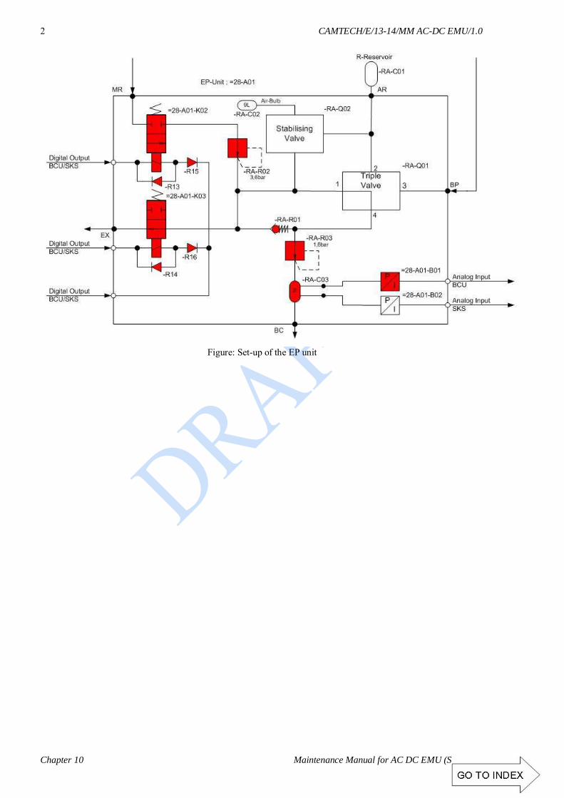
CAMTECH/E/13-14/MM AC-DC EMU/1.0
Chapter 10 Maintenance Manual for AC DC EMU (Siemens)
2
Figure: Set-up of the EP unit

CAMTECH/E/13-14/MM AC-DC EMU/1.0
Maintenance Manual for AC-DC EMU (Siemens) Chapter 10
3
Figure: Set-up of the brake system DTC – MC – TC

CAMTECH/E/13-14/MM AC-DC EMU/1.0
Chapter 10 Maintenance Manual for AC DC EMU (Siemens)
4
Figure: Set-up of the brake system NDTC – MC – TC

CAMTECH/E/13-14/MM AC-DC EMU/1.0
Maintenance Manual for AC-DC EMU (Siemens) Chapter 10
5
Figure: Overview of spring-loaded brake
The spring-loaded brake is suitable for securing the units. It acts on the two bogies of the DTC / NDTC. Compressed air is required to release the brake. In the case of a broken or defect hose, the spring-loaded brake is applied automatically. However, this fault can be eliminated via the emergency release device, i.e. one funicular traction per spring-loaded brake on the bogie. It is no longer possible to apply the spring-loaded brake after a fault of this kind. In addition, the shut-off cock of the spring-loaded brake must always be shut-off for an emergency release.
Air reservoir
Emergency release device
Holding valve
Compressed-air brake cylinder
Spring-loaded brake cylinder
BP connection
Solenoid valve
Manometer in the driver's
cab
Figure: Shut-off cock of the spring-loaded brake and emergency release device
Release device
Shut-off cock of the spring-loaded brake


CHAPTER 11
PASSENGER AMMENITIES

CONTENTS
S.No. Description Page No. 11.1 COACH FANS 01 11.2 COACH LIGHT 01 11.3 AIR VENTILATION & MAIN BLOWER UNITS 02 11.4 PASSENGER INFORMATION SYSTEM 02

CAMTECH/E/13-14/MM AC-DC EMU/1.0
Maintenance Manual for AC-DC EMU (Siemens) Chapter 11
1
CHAPTER 11
PASSENGER AMMENITIES
11.1 COACH FANS
Technical data Sr.No. Description : Coach Fan AC-DC EMU
1 Make : M/s Raman Sinha ( Shankar) 2 Voltage : 98-135 V AC, 50 Hz AC
3 Power : 65 W 4 Power factor : 0.9
5 Sweep : 450 mm 6 RPM : 1200
7 Air Delivery : 85 m3/ min 8 Wire mesh & Body : Aluminium
9 Fan Blade : Nylon
11.2 COACH LIGHT

CAMTECH/E/13-14/MM AC-DC EMU/1.0
Chapter 11 Maintenance Manual for AC DC EMU (Siemens)
2
11.3 AIR VENTILATION & MAIN BLOWER UNITS
Make Siemens Type 2CS7 352-8RG11-1EM8 Motor Make Siemens Motor Type of motor 1PP9083-2LA99ZN03 Nominal voltage 3AC, 415V ±10% @ 50Hz Starting current and torque 24.4A / 22.0Nm Continuous rating (at shaft) 1.75kW Speed (at rated power) 2840 rpm Power factor and slip of the motor (at rated power) 0.82 slip: 5.3% Power consumption at rated capacity (Working point) 1.6 kW Output power at shaft (working point) 1.25 kW Efficiency at rated capacity Motor 77.5 %
Blower 49% 11.4 PASSENGER INFORMATION
SYSTEM
Display unit

CHAPTER 12
MAINTENANCE SHEDULES
FOR
AC – DC EMU (SIEMENS)
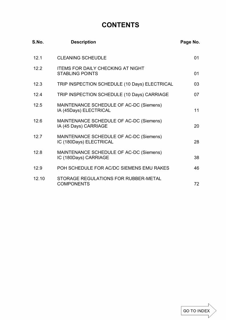
CONTENTS
S.No. Description Page No. 12.1 CLEANING SCHEUDLE 01 12.2 ITEMS FOR DAILY CHECKING AT NIGHT STABLING POINTS 01 12.3 TRIP INSPECTION SCHEDULE (10 Days) ELECTRICAL 03 12.4 TRIP INSPECTION SCHEDULE (10 Days) CARRIAGE 07 12.5 MAINTENANCE SCHEDULE OF AC-DC (Siemens) IA (45Days) ELECTRICAL 11 12.6 MAINTENANCE SCHEDULE OF AC-DC (Siemens) IA (45 Days) CARRIAGE 20 12.7 MAINTENANCE SCHEDULE OF AC-DC (Siemens) IC (180Days) ELECTRICAL 28 12.8 MAINTENANCE SCHEDULE OF AC-DC (Siemens) IC (180Days) CARRIAGE 38 12.9 POH SCHEDULE FOR AC/DC SIEMENS EMU RAKES 46 12.10 STORAGE REGULATIONS FOR RUBBER-METAL COMPONENTS 72

CAMTECH/E/13-14/MM AC-DC EMU/1.0
Maintenance Manual for AC-DC EMU (Siemens) Chapter 12
1
CHAPTER 12
MAINTENANCE SHEDULES FOR AC – DC EMU (SIEMENS)
REF: SMI for uniform periodicity of maintenance schedules for EMU (AC & DC) &MEMU coaches (ref: RDSO / PE / SMI / EMU / 0037 -2007, Rev. 0, April 2007)
1. The various maintenance schedules periodicity for AC EMU/MEMU stock as
given below should also be applicable to AC – DC EMU stock plying in Mumbai area.
2. Due attention to be paid to passenger amenities items mentioned in para ‘B’ from trip inspection onwards.
LEGENDS USED:
TI Trip Inspection POH 18 months Inspection
IA 45 Days Inspection IC 180 Days Inspection
TYPE OF SCHEDULE AND PERIODICITY FOR AC, AC - DC EMU/MEMU
Type of Schedule Periodicity Daily/ Night - Trip Inspection (TI) 10 Days IA 45 Days 6 Monthly (IC) 180 Days POH 18 Months
12.1 CLEANING SCHEUDLE
Washing of exteriors & wet mopping of interiors shall be done during trip inspection and brooming must be done at night stabling points every day.
12.2 ITEMS FOR DAILY CHECKING AT NIGHT STABLING POINTS
(Ref: RDSO / PE / SMI / EMU / 0037 -2007,Rev. 0, April 2007)
1. Visual Inspection of wheels for cracks, checking of axle boxes, its cover and bolts. 2. Check axle guide springs, air springs, bogie frame and all brake riggings. Also
check schaku couplers and side buffers. 3. Check brake blocks for their position and replacements if required.
4. Drain main reservoirs. 5. Check main compressor for their oil level.

CAMTECH/E/13-14/MM AC-DC EMU/1.0
Chapter 12 Maintenance Manual for AC DC EMU (Siemens)
2
6. Check gear case suspension housing bolts etc.
7. Check all compartment lights & fans. 8. Check and test horns, wiper, dead man device, guard emergency brake.
9. Check and clean head code, look out glasses.
10. Check fire extinguishers, locking of HT compartment, driving cabs.
11. Ensure all indications lamps functioning. 12. Formation testing from both the ends and brake testing.
13. Check for all hoses, air pipes. 14. Specially check headlights, taillight and flasher lights.
15. Check for battery voltage. 16. Visual check for any oil leakage from transformer, radiator and pipe lines.
17. Go through the motorman logbook and attend the defects booked during the run. 18. Record in the logbook any other abnormalities, which need attention in shed, but
ensure safety and reliability. Para ‘B’ (SMI / EMU / 0037 -2007) Passenger Amenities Items
Due attention to be paid to passenger amenities items mentioned below from trip inspection onwards.
S. No. ITEMS
1. Broken seats and seats frame.
2. Worn out / broken chequered plates in doorways.
3. Missing glass and louver shutter including complete window frame.
4 Missing doors.
5. Worn out / tilted foot steps
6. Missing overhead handles and hand rails.
7. Breakage of FRP panel (interior panels).
8. Missing of different types of angles/ moldings.
9. Missing of seat fittings.
10. Missing of tread plate of door.
11. Missing of luggage rake.
12. Missing of notice plates and ACP handles.
13. Condition of chequered plates.
14. Proper head code working.
15. Proper working of compartment Light & Fan. Changing of defective lamp, fan fitting etc.

CAMTECH/E/13-14/MM AC-DC EMU/1.0
Maintenance Manual for AC-DC EMU (Siemens) Chapter 12
3
12.3 TRIP INSPECTION SCHEDULE (10 Days) ELECTRICAL
Sr. Items to be checked Remark 1.0 Driving cab i) Check E-Cabinet for any isolation of Switches &
MCBs.
ii) Down load fault events from both CCUs and all the TCUs and analyze for faults.
2.0 Light & Fan i) Check operation of Lights, Fans and Ventilation
switches on both positions 50% &100%.
ii) Check the working of all Fans and Lights in the coaches. Attend the defects noticed.
iii) Check working of Signal Bell / Emergency Bell & indication LEDs.
iv) Check working of Flasher, Tail & Blinker Light and ensure smooth operation of their Push Buttons.
v) Check working of Head Light & Auxiliary Head Lights at both Dim/ Bright positions.
vi) Check working of DC-DC Converter for Head Light on both normal and standby positions.
vii) Check working of Cab Light, Emergency Cab Light, Spot Light & Cab Fans.
viii) Ensure smooth operation of all push buttons & switches in the D/ Cab.
3.0 Battery i) Check & record Battery Voltage of individual unit by
operating "TEST BATTERY VOLTAGE" push button in motor coach shunting cab.
100V to 110v
ii) Check for intactness of Battery Box mounting Bracket and Bolts.
4.0 Transformer i) Check oil level. Check for any oil leakage.
ii) Check for any hitting / damage signs. iii) Check intactness of Transformer Mounting Bolts and
availability of safety slings.
iv) Check the colour of silica gel. Orange -ok , Grey- Not OK
6.0 Control and Switch Gear i) Check all MCBs & Switches for normal position on
the E-Cabinet in the Motor Coach.
ii) Check for set condition of Motor Protection Switch (MPS) in all the end panels.
iii) Ensure proper locking of panel doors of E-Cabinet in D/cab & MC, End wall panels in all the coaches.

CAMTECH/E/13-14/MM AC-DC EMU/1.0
Chapter 12 Maintenance Manual for AC DC EMU (Siemens)
4
Sr. Items to be checked Remark iv) Ensure proper position of MVB
segment address selector switch in all motor coaches.
Rake U1 U2 U3 U4 9 Car 0 1 5 - 12 Car 0 1 2 5 15 Car 0 1 2 3
7.0 Roof Equipment i) Check for any signs of external hitting/ damages/ cracks
on pantograph and other roof equipment. ii) Check for any OHE rubbing marks on panto pan below
Red mark. iii) Check thickness of copper Wearing Strips. It should be
above condemning size. > 3mm
iv) Check that wearing Strips are without Sharp Edges and ensure Screws are not projecting above the wearing strips and are properly secured.
v) Check that there is no Gap between the Main wearing and End wearing Strips.
vi) Ensure availability of all Bolts, Nuts, Lock-Nuts, Spring Washers, Split pins etc. of various fittings.
vii) Ensure intactness of middle Articulation Assembly shaft check nut.
ix) Check Bow Plunger is sliding freely while pressing and split pins are available (SIL). Check Rocker assembly for free movement (Schunk).
x) Check the Control Box, Rubber Bellow & Rubber/PU Pipe for any air leakage. (Schunk) Check the Servo motor, Throttle Valve, Magnet Valve for Any air leakage. (SIL)
xi) Check Horizontal Damper for Oil Leakage and smooth operation (Schunk).
xii) Check for free movement of servo motor piston rod and eyelet rod. (SIL)
xiii) Ensure availability of all flexible shunts and check that strands are not broken.
xiv) Ensure provision of steel bracket on lower articulation to prevent earthing of anti balancing tube after uncoupling.
xv) Check whether rubber stopper on the base frame and MS bracket on lower articulation is provided to prevent over turning of panto in unwired section (SIL).
xvi) Check & record Raising and Lowering time of antograph 6-10 Sec
xvii) Ensure pantograph is raising in three steps.

CAMTECH/E/13-14/MM AC-DC EMU/1.0
Maintenance Manual for AC-DC EMU (Siemens) Chapter 12
5
Sr. Items to be checked Remark xviii) Clean all the roof Insulators with Vim powder & dry
cloth.
xix) In case flashing marks are noticed on the insulators, clean and apply anti tracking varnish on the flashed portion.
8.0 Main Air Compressor (Mac)
i) Check for any Oil or Air Leakage from Joints, Radiator, Suction/ Delivery pipes and safety valves.
ii) Check for any hitting mark/damage to the radiator.
iii) Check for intactness of resilient mounting.
iv) Check for any abnormal sound & excess Heat during run.
v) Check Cut in & Cut out pressure of compressor governors.
Cut in 7.0 Kg/cm² Cut out 8.0 Kg/cm²
9.0 Auxiliary Compressor
i) Check Oil Level and for any oil/ air leakage.
ii) Check the Tightness of Foundation Bolts and other fittings.
iii) Ensure proper function of Aux Compressor & its governor.
Cut in 5.3 Kg/cm² Cut out 6.3 Kg/cm²
10.0 APC Magnet
i) Check intactness of mounting bolts.
ii) Check intactness and proper securing of cable conduit.
11.0 Final Testing (From Both D/Cabs) i) Keep MMI in Maintenance Mode
ii) Check Healthiness of various Lamp Indication by Pushing Test Push Button.
iii) Check on MMI that all coaches are set. iv) Check the Healthiness of each and every function
physically which are displayed on various screens. (Top level, Unit Level, Drive/ Brake, Energy, Fault logged, V > 0 & V = 0) of MMI.
v) Check for any Error Message on the screen. vi) Check ground fault in 110V DC and 110V AC circuit
by multi-meter. Record voltage between (45-55 V) +ve to ground -ve to ground.
vii) Check CB set/ trip on MMI. viii) Check Panto Raising/Lowering timing on MMI. 6-10 Sec ix) Check working of Fan, Light and Ventilation (both
50% and 100%)

CAMTECH/E/13-14/MM AC-DC EMU/1.0
Chapter 12 Maintenance Manual for AC DC EMU (Siemens)
6
Sr. Items to be checked Remark
x) Check Changeover on MMI for 415V AC, 110V AC, 110V DC by operating Basic Unit Isolating Switch.
xi) Check operation of Head Light, Auxiliary Head Light, Flasher, Tail Light and Blinker Lights on various positions.
xii) Check operation of Signal bell and Emergency bells and their indication.
xiii) Check working of PA/PIS & TMS system. Intercom, Passenger address , PIS, TMS
xiv) Check for Healthiness of Head-code.
xv) Check functionality of Entering Neutral Section Push Button by observing feedback on SKS 12 & 13.
xvi) Check operation of "Battery Supply " switch
xvii) Check working of Emergency OFF Loop push Button.
xviii) Observe all Sensors Feed Back Signals in "Observer" by laptop speed sensors, BC pressure.
xiv) Ensure AWS working by Pressing vigilance Push button for 8 sec.
xv) Check working of Dead man valve in normal and RDM mode .
xvi) Measure and record the rate of air flow of ACU & TCU blowers of all four Motor coaches ACU > 5-6m/s, TCU > 7-9 m/s
U1 U2 U3 U4 TCU --------- ACU ---------
xvii) Check working of audio visual and cross passing.
xviii) Run down the Rake in Normal and RDM mode.
xix) Check AWS Speedometer and Speed Recorder and ensure no differential error occurs from both cabs.
xx) Revert to "Drive Mode" on MMI after completion of testing.
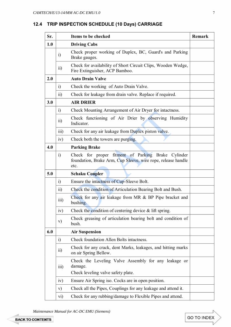
CAMTECH/E/13-14/MM AC-DC EMU/1.0
Maintenance Manual for AC-DC EMU (Siemens) Chapter 12
7
12.4 TRIP INSPECTION SCHEDULE (10 Days) CARRIAGE
Sr. Items to be checked Remark
1.0 Driving Cabs
i) Check proper working of Duplex, BC, Guard's and Parking
Brake gauges.
ii) Check for availability of Short Circuit Clips, Wooden Wedge, Fire Extinguisher, ACP Bamboo.
2.0 Auto Drain Valve
i) Check the working of Auto Drain Valve.
ii) Check for leakage from drain valve. Replace if required.
3.0 AIR DRIER
i) Check Mounting Arrangement of Air Dryer for intactness.
ii) Check functioning of Air Drier by observing Humidity Indicator.
iii) Check for any air leakage from Duplex piston valve.
iv) Check both the towers are purging.
4.0 Parking Brake
i) Check for proper fitment of Parking Brake Cylinder
foundation, Brake Arm, Cup Sleeve, wire rope, release handle etc.
5.0 Schaku Coupler
i) Ensure the intactness of Cup-Sleeve Bolt.
ii) Check the condition of Articulation Bearing Bolt and Bush.
iii) Check for any air leakage from MR & BP Pipe bracket and bushing.
iv) Check the condition of centering device & lift spring.
v) Check greasing of articulation bearing bolt and condition of bush.
6.0 Air Suspension
i) Check foundation Allen Bolts intactness.
ii) Check for any crack, dent Marks, leakages, and hitting marks on air Spring Bellow.
iii) Check the Leveling Valve Assembly for any leakage or damage. Check leveling valve safety plate.
iv) Ensure Air Spring iso. Cocks are in open position.
v) Check all the Pipes, Couplings for any leakage and attend it.
vi) Check for any rubbing/damage to Flexible Pipes and attend.

CAMTECH/E/13-14/MM AC-DC EMU/1.0
Chapter 12 Maintenance Manual for AC DC EMU (Siemens)
8
Sr. Items to be checked Remark
7.0 Piping And Reservoirs
i) Check for any air leakage, ensure availability of all clamps.
ii) Check Welding Joints, Split Pins, and Fixing Bolts of all the air reservoirs.
iii) Ensure that the Reservoirs are intact with MS straps.
iv) Check for isolation of EP/AUTO/Bogie & coupling cocks
v) Check for any Damage to Piping and Cocks. Replace defective / leaking cocks.
8.0 BOGIE
i) Check Bogie frame, Bolster and coach under-frame for any crack / damage.
ii) Check coach sole-bar and under frame for any crack/ hitting marks.
iii) Check condition of liner between Bogie & Bolster.
iv) Check for healthiness and foundation intactness of lateral and vertical friction dampers.
v) Check Palm-pull rods for any crack/ bending. Check condition of bushes, pins and safety Chains.
vi) Check availability of pins with Bulb Cotters & Split Pins.
vii) Check Side Bearer for Crack or Oil Leakage.
ix) Check for Side Bearer cover jam/ loose.
x) Check for bolt tightness of Center Pivot or any crack.
xi) Check Axle Springs for any Breakage/ Permanent set.
xii) Check and ensure the intactness of Cattle guard, Buffer foundation Bolts.
9.0 BRAKE CYLINDER
i) Check fixing Bolts of Brake Cylinders for any damage or slackness.
ii) Check Brake Rigging parts i.e. pins, Nut Bolts, Cutters, Split Pins of Brake Block key shoe head pins for missing, worn out, slackness.
iii) Check Brake Hanger Safety Brackets and Safety Stopper Plates are intact.
iv) Replace worn out Brake Blocks.
v) Ensure sufficient Gap between Brake Block and Wheel. >12 mm
vi) Check Brake Cylinder Piston not infringing with U Bracket in brake applied condition.
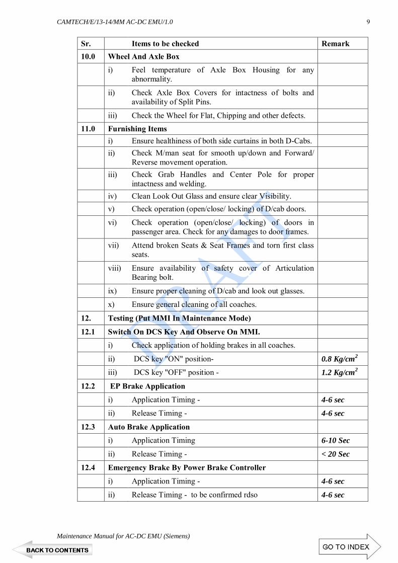
CAMTECH/E/13-14/MM AC-DC EMU/1.0
Maintenance Manual for AC-DC EMU (Siemens) Chapter 12
9
Sr. Items to be checked Remark 10.0 Wheel And Axle Box
i) Feel temperature of Axle Box Housing for any abnormality.
ii) Check Axle Box Covers for intactness of bolts and availability of Split Pins.
iii) Check the Wheel for Flat, Chipping and other defects. 11.0 Furnishing Items i) Ensure healthiness of both side curtains in both D-Cabs. ii) Check M/man seat for smooth up/down and Forward/
Reverse movement operation.
iii) Check Grab Handles and Center Pole for proper intactness and welding.
iv) Clean Look Out Glass and ensure clear Visibility. v) Check operation (open/close/ locking) of D/cab doors.
vi) Check operation (open/close/ locking) of doors in passenger area. Check for any damages to door frames.
vii) Attend broken Seats & Seat Frames and torn first class seats.
viii) Ensure availability of safety cover of Articulation Bearing bolt.
ix) Ensure proper cleaning of D/cab and look out glasses.
x) Ensure general cleaning of all coaches.
12. Testing (Put MMI In Maintenance Mode)
12.1 Switch On DCS Key And Observe On MMI.
i) Check application of holding brakes in all coaches.
ii) DCS key "ON" position- 0.8 Kg/cm2
iii) DCS key "OFF" position - 1.2 Kg/cm2
12.2 EP Brake Application
i) Application Timing - 4-6 sec
ii) Release Timing - 4-6 sec
12.3 Auto Brake Application
i) Application Timing 6-10 Sec
ii) Release Timing - < 20 Sec
12.4 Emergency Brake By Power Brake Controller
i) Application Timing - 4-6 sec
ii) Release Timing - to be confirmed rdso 4-6 sec

CAMTECH/E/13-14/MM AC-DC EMU/1.0
Chapter 12 Maintenance Manual for AC DC EMU (Siemens)
10
Sr. Items to be checked Remark 12.5 Emergency Brake By Brake Controller
i) Application Timing - 6-10 Sec
ii) Release Timing - < 20 Sec
12.6 Check The Following During Brake Application And Releasing
i) Air leakage from Brake units/ Brake Cylinder / Pipeline / Reservoir / Safety Valve. No Leakage
ii) Ensure No EP Unit is hunting.
iii) Safety valve should be blowing during Auto Brake Application only.
iv) Check for free movement of Brake Cylinder Piston during application & releasing.
v) In case of Late Releasing of brake on MMI, identify the particular coach by going to Unit and attend.
vi) Check working of parking brake Application /Releasing Push Button.
vii) Ensure during parking Brake application PB gauge showing 0.0 kg/cm2 and during releasing 5.0Kg/cm2
ix) Verify working of Parking Brake Cylinder in all the Coaches.
x) Check working of Emergency Valve in Normal and RDM from both the Cabs.
xi) Check working of Guard Emergency Handle from both cabs.
xii) Check working of hooter from both cabs (M/Man and GD side) and ensure no leakage from Horn Foot valve.
xiii) Check BP, Charging Time from Both the D/cabs. 90-120 sec
ix) Measure brake pipe pressure on Duplex gauge. ICS ON Cab-1 ICS ON Cab-2
BP Cab-1_____ BP Cab-2_____ BP Cab-1_____ BP Cab-2_____

CAMTECH/E/13-14/MM AC-DC EMU/1.0
Maintenance Manual for AC-DC EMU (Siemens) Chapter 12
11
12.5 MAINTENANCE SCHEDULE OF AC-DC (Siemens) IA (45Days) ELECTRICAL
Sr. Description Remark 1.0 Pre-Testing
1.1 Keep MMI in Maintenance Mode. 1.2 Check on MMI that all coaches are set.
1.3
Check the Healthiness of each and every function physically which are displayed on various screens (Top level, Unit Level, Drive/Brake, Energy, Fault logged, V > 0 & V = 0) of MMI.
1.4 Check for any Error Message on the screen.
1.5 Check ground fault in 110V DC circuit by multi-meter. Record voltage between (45 - 55 V) '+ve to ground, -ve to ground.
1.6 Check ground fault in 110V AC circuit by multi-meter. Record voltage between ( 45 - 55 V).
1.7 Check and ensure all MCB are set on E-Cabinet.
1.8 Check and ensure all rotary switches are set in their relevant normal position in E-Cabinet.
1.9 Check CB set/trip on MMI.
1.10 Check Changeover on MMI for 415V AC, 110V AC, 110V DC by operating Basic Unit Isolating Switch.
1.11 Check functionality of Entering Neutral Section Push Button by observing feed-back on SKS 12 & 13.
1.12 Check operation of "BA Reset" switch 1.13 Check working of Emergency OFF Loop push Button.
1.14 Observe BECU Speed Sensors Feed Back Signals in "Observer" by laptop.
1.15 Check working of Dead man’s valve in normal and RDM mode .
1.16 Ensure the functions of E-Cabinet switches.
1.17 Measure the rate of air flow of ACU of all four Motor coaches after filter cleaning.
> 5-6 m/s
1.18 Measure the rate of air flow of TCU blowers of all four Motor coaches after air blowing.
> 8-9m/s
1.19 Check working of audio visual.
1.20 Down load the events of all Four TCU & both CCU and analyze for any fault message.
1.21 Take energy consumed readings and reset the both counters.
1.22 Take energy re-generated readings and reset the both counters.
1.23 Take distance (km) readings and reset the both counters. 1.24 Ensure correct position of check nut in Escorts make ICS.
1.25 Note the brake cylinder pressures in each coach with SIBAS monitor both normal redundant modes of BCU.

CAMTECH/E/13-14/MM AC-DC EMU/1.0
Chapter 12 Maintenance Manual for AC DC EMU (Siemens)
12
Sr. Description Remark 2.0 Master Controller
2.1 Check the operation of Dead-man, Forward/ Reverse, DCS Key, Traction, brake and coast position.
2.2 Visually check Encoder cable for any insulation damage.
2.3 Check all electrical & micro switches connections for intactness.
2.4 Visually check the operation of all micro switches 2.5 Ensure no excessive play in T-handle. 3.0 Push buttons & Switches.
3.1 Check & ensure smooth operation with their indications of all push buttons on Driver desk.
3.2 Check Healthiness of various Lamp Indications by Pushing Test Push Button.
3.3 Check the operation of all the switches. 4.0 End wall
4.1 Check intactness of wiring connection at MCB, Relays, Contactors etc. of all D cabs.
5.0 Transformer
5.1 Check colour of silica gel. It should ORANGE. Heat/replace the silica gel if found grey.
5.2 Check for any oil leakage. 5.3 Check working of radiator blower fans & oil pump. 5.4 Check for any hitting mark or damage. 5.5 Transformer cleaning to be done.
5.6 Oil level to be checked. It should be in-between low level and 300 mark.
5.7 Ensure Earthing connection intactness. 5.8 Check the foundation bolts intactness. 5.9 Ensure Radiator fins cleanliness. 6.0 Traction Motor
6.1 Record the temperature at DE and NDE side of traction motor bearings by temperature gun.
While rake placed in shed
6.2 Visual inspection for any external hitting or damage.
6.3 Check intactness of TM mounting bolts & MSU half shell bolts.
6.4 Check tightness of Gear case bolts. 6.5 Check the oil level and colour of gear case oil. 6.6 Check intactness of body earthing.
6.7 Check for rubbing and damage of Traction Motor cables and their proper securing.
6.8 Visual inspection for damage to sandwich packing. 6.9 Clean suction air filters by dry compressed air.

CAMTECH/E/13-14/MM AC-DC EMU/1.0
Maintenance Manual for AC-DC EMU (Siemens) Chapter 12
13
Sr. Description Remark 6.10 Check for proper fitment and tightness of bellow. 6.11 Check for any damage. Replace if required. 7.0 Motor Suspension Unit (MSU) 7.1 Check for any sign of over-heating of bearings. 7.2 Check that the housing bolts are intact. 7.3 Check for any abnormality. 8.0 Main Compressor 8.1 Clean externally compressor body & radiator.
8.2 Check operation of compressor by way of observing running sound, feel temperature by hand.
8.3 Check for any oil or air leakage from joints, suction or delivery pipes.
8.4 Ensure oil level. 8.5 Check condition of resilient mounting for intactness. 8.6 Check & ensure tightness of foundation bolts.
8.7 Check vacuum indicator on silencer (suction filter) i) Colourless - ok ii) Red Colour - Suction filter defective
8.8 Ensure proper tightness of delivery pipe. 8.9 Ensure the healthiness of mounting wire ropes. 8.10 Clean air suction filters by dry compressed air. 8.11 Check pressure built up time of each Unit ( 0- 7 kg/cm2) 10-12 min
8.12 Check Cut in & Cut Out Setting of Main air Compressor Cut in 6.0 kg/cm² Cut out-7.0 kg/cm²
9.0 Auxiliary Compressor 9.1 Check the carbon brush, if required to be replaced. 9.2 Check oil level. Top up if required. 9.3 Check for any leakage of oil and air. 9.4 Drain auxiliary Compressor air reservoir. 9.5 Check the foundation bolts. 9.6 Check & Record time to build up pressure 0 to 5.0 kg/cm² within 4 min
9.7 Check Cut in & Cut Out Setting of Auxiliary Compressor. Cut in 5.3 kg/cm² Cut out-6.3 kg/cm²
9.8 Check battery voltage with auxiliary compressor ON. 10.0 TCC & ACU 10.1 Clean the air intake jally of TCC / Module heat sink. 10.2 Check working of TCC blowers. 10.3 Intactness of grounding shunts. 10.4 Check the intactness of VSS cable connections. 10.5 Cleaning of TCC, ACU cabinet.

CAMTECH/E/13-14/MM AC-DC EMU/1.0
Chapter 12 Maintenance Manual for AC DC EMU (Siemens)
14
Sr. Description Remark 11.0 L.A, C.T. & P.T.
11.1 Clean the insulators. 11.2 Check the HT Connection intactness. 11.3 Check the intactness of foundation bolts. 11.4 Check for any crack on the insulators.
12.0 Pantograph & Roof Equipment
12.1
Check for any sign of external hitting / damages / cracks on Panto Pan, Rocker Assembly, Lower Frame ,Upper Frame, Base Frame, Coupling Rod, Parallel Guide Bar (Schunk) Raising Springs, Tension bolts, Anti-balancing rod, upper articulation, Lower articulation, Eye-let Rod and Other Sub Assemblies of pantograph. In case of any abnormality replace it (SIL).
12.2 Check for any OHE rubbing marks on panto pan below Red paint line.
12.3 Check thickness of Wearing Strips. It should be above condemning size.
> 3 mm
12.4 Check that wearing Strips are without Sharp Edges and ensure Screws are not projecting above the wearing strips and are properly secured.
12.5 Check that there is no Gap between the Main wearing and End wearing Strips.
12.6 Ensure availability of all Bolts, Nuts, Lock-Nuts, Spring Washers, Split pins etc. of various fittings .
12.7 Check Lower Frame Assembly & Upper Frame Assembly for excessive lateral play (transverse).
12.8 Check Bow Plunger is sliding freely while pressing and split pins are available (SIL). Check Rocker assembly for free movement (Schunk).
12.9
Check the Control Box, Rubber Bellow & Rubber/PU Pipe for any air leakage.(Schunk) Check the Servo motor, Throttle Valve, Magnet Valve for Any air leakage.(SIL)
12.10 Check Horizontal Damper for Oil Leakage and smooth operation (Schunk).
12.11 Check for free movement of servo motor piston rod and eyelet rod. (SIL)
12.12 Ensure availability of all flexible shunts and check that strands are not broken.
12.13 Ensure provision of steel bracket on lower articulation to prevent earthing of anti balancing tube after uncoupling.

CAMTECH/E/13-14/MM AC-DC EMU/1.0
Maintenance Manual for AC-DC EMU (Siemens) Chapter 12
15
Sr. Description Remark
12.14 Check whether rubber stopper on the base frame and MS bracket on lower articulation is provided to prevent over turning of panto in unwired section. (SIL)
12.15 Check & record Raising and Lowering time of Pantograph. 6-10 Sec
12.16 Ensure pantograph is raising in three steps in SIL.
12.17 Clean all the Insulators with vim powder & dry cloth.
12.18 Air blow the DBR.
12.19 Visual check for any damage to grid, flashover.
12.20 Check for HT connection intactness.
12.21 Check and ensure that there is no Air Leakage from the Panto magnet valve.
12.22 Check panto pan tension. 10.5 kg (Shunk) 9.5 kg ( SIL)
13.0 VCB (Single bottle)
13.1 Check foundation bolts tightness.
13.2 Check the tightness Electrical connections.
13.3 Check for cracks and flash marks.
13.4 Clean the insulators.
13.5 Check for connection of AC earthing switch.
13.6 Clean and grease the AC earthing switch.
13.7 Check for any air leakage in VCB pneumatic connection.
14.0 DC Earthing switch
14.1 Clean & Grease the moving and fixed contact of earthing switch.
14.2 Ensure Connection tightness.
15.0 Change over switch
15.1 Check the HT Connection intactness.
15.2 Check the foundation bolts.
15.3 Clean insulator using Vim powder.
15.4 Check visually for any crack/damage.
15.5 Check tightness of all cable connections.
16.0 Control and Switch Gear
16.1 Check all MCBs & Switches for normal position on the E-Cabinet in the Motor Coach.
16.2 Check for set condition of Motor Protection Switch (MPS) in all the end panels.

CAMTECH/E/13-14/MM AC-DC EMU/1.0
Chapter 12 Maintenance Manual for AC DC EMU (Siemens)
16
Sr. Description Remark
16.3 Ensure proper locking of panel doors of E-Cabinet in D/cab & MC, End wall panels other coaches.
16.4 Ensure proper position of MVB segment address selector switch.
17.0 AWS
17.1 Note the defects reported in defect card book.
17.2 Check and note the reading of SFBC, EBC, ISU
17.3 Ensure the intactness of ISU, BAU, Indication panel, PCB card frame, Elmex terminal, magnet valve, SPM hooter & tightness of wire connections
17.4 Check the ISU handle for proper fitment & tightened if found loose.
17.5 Ensure functioning of SPM hooter and BAU.
17.6 Check AWS MCB and ground fault.
17.7 Set wheel diameter in B4A1 card.
17.8 Function test pressure test, SPM test & simulation test to be done.
17.9 Replace speed cut off and exhaust magnet valve. 9 monthly basis
17.10
Check & note the Engine magnet pulses on B1A1 card by multimeter
50 Khz-socket 1 & 3 200 +/_ 20 mv
100 Khz – soket 5 & 7 350 +/ - 25mv
17.11
Check voltage on B14A1 card
Socket 1-2 12v +/- 0.3 v, 0.6v
Socket 3-2 24v +/- 1.1v, 0.6v
Socket 4-5 5v +/- 0.3v
17.12 Download medha/ AAL SPM data
17.13 Ensure intactness of Engine magnet foundation beam, engine magnet, JB-1, JB-II, TGs, magnet valve & cover, pipes & clamping, all fastners, washer, split spins, safety chains etc.
17.14 Check the clearance of engine magnet clearance from the rail.
17.15 Ensure TG axle attachment, dowel pins fork.
17.16 Ensure the SPM is showing speed by manually rotating TG in both directions. Ensure no brake is applied in forward direction and brake applied in reverse direction.
18.0 APC
18.1 Ensure proper intactness of foundation hardware of APC magnet.

CAMTECH/E/13-14/MM AC-DC EMU/1.0
Maintenance Manual for AC-DC EMU (Siemens) Chapter 12
17
Sr. Description Remarks
18.2 Check for intactness of electrical coupler.
18.3 Ensure functioning of APC receiver by passing over APC track magnet and ensure same at SIBAS clip also. Ensure reset of APC also.
19.0 Fire Extinguisher
19.1 Check for seal is intactness.
19.2 Check for refilling date & Replace if expired.
19.3 Check for fire extinguisher mounting.
19.4 Check the condition of nozzle/ pipe & replace if punctured.
20.0 PIS/PA System & TMS
20.1 Check working of intercom.
20.2 Check working of public address from both cab.
20.3 Check working of PIS from both cabs by entering any journey.
20.4 Ensure availability of manual head code.
20.5 Check working of coach display and speakers.
21.0 Light & Fan
21.1 Check operation of Lights, Fans and Ventilation switches on 50% &100% position.
21.2 Check the working of all Fans and Lights in the coaches. Attend the defects if noticed.
21.3 Check working of Signal Bell / Emergency Bell & indication LEDs.
21.4 Check working of Flasher, Tail & Blinker Light and ensure smooth operation of their Push Buttons.
21.5 Check working of Head Light & Auxiliary Head Lights at both Dim/ Bright positions.
21.6 Check working of DC-DC Converter for Head light on both normal and standby positions.
21.7 Check head light focus and adjust if required.
21.8 Check working of Cab Light, Emergency Cab Light, Spot Light & Cab Fans.
21.9 Ensure smooth operation of all push button & switches in the D/ Cab.
22.0 BATTERY
22.1 Check & record Battery Voltage by operating "TEST BATTERY VOLTAGE" push button in motor coach shunting cab after switching off battery.
22.2 Check for intactness of Battery Box mounting Bracket and Bolts.

CAMTECH/E/13-14/MM AC-DC EMU/1.0
Chapter 12 Maintenance Manual for AC DC EMU (Siemens)
18
Sr. Description Remarks
22.3 Check the battery voltage when MC charged & record it.
22.4 Check the condition of battery cover, battery box for proper fitment.
22.5 Check the condition of battery connecting leads.
22.6 Ensure intactness of lead connections.
22.7 Check the level of electrolyte in each cell &Top up if less.
22.8 Check the voltage of each cell.
22.9 Check the specific gravity of each cell.
22.10 Apply petroleum jelly on all connections after cleaning.
22.11 Clean the battery box & trolley.
22.12 Ensure proper working of trolley & door hinges.
22.13 Ensure compact placement of battery cells to avoid relative movement during run.
23.0 Final Testing from both Driving CABs
23.1 Keep MMI in Maintenance Mode
23.2 Check Healthiness of various Lamp Indication by Pushing Test Push Button .
23.3 Check on MMI that all coaches are set.
23.4
Check the Healthiness of each and every function physically which are displayed on various screens. (Top level, Unit Level, Drive/Brake, Energy, Fault logged, V > 0 & V = 0) of MMI.
23.5 Check for any Error Message on the screen.
23.6 Check ground fault in 110V DC and 110V AC circuit by multi-meter. Record voltage between (45 - 55 V) + ve to ground and -ve to ground.
23.7 Check CB set/trip on MMI.
23.8 Check Panto Raising/Lowering timing on MMI. 6-10 Sec
23.9 Check working of Fan, Light and Ventilation (both 50% and 100%).
23.10 Check Changeover on MMI for 415V AC, 110V AC, 110V DC by operating Basic Unit Isolating Switch.
23.11 Check operation of Head Light, Auxiliary Head Light, Flasher, Tail Light and Blinker Light.
23.12 Check operation of Signal bell and Emergency bells and their indication.
23.13 Check working of PA/PIS & TMS system.
23.14 Check for Healthiness of Head-code.

CAMTECH/E/13-14/MM AC-DC EMU/1.0
Maintenance Manual for AC-DC EMU (Siemens) Chapter 12
19
Sr. Description
23.15 Check functionality of Entering Neutral Section Push Button by observing feed-back on SKS 12 & 13.
23.16 Check operation of "Battery Supply " switch.
23.17 Check working of Emergency OFF Loop push Button.
23.18 Ensure AWS working by Pressing vigilance Push button for 8 sec.
23.19 Check working of Dead man’s valve in normal and RDM mode .
23.20 Measure and record the rate of air flow of ACU & TCU blowers of all four Motor coaches.
ACU>5-6m/s TCU>7-9 m/s
23.21 Check working of audio visual and cross passing.
23.22 Run down the Rake in Normal and RDM mode from both cabs.
23.23 Check AWS Speedometer and Speed Recorder and ensure no differential error in both cabs.
23.24 Revert MMI to "Drive Mode" after completion of testing.

CAMTECH/E/13-14/MM AC-DC EMU/1.0
Chapter 12 Maintenance Manual for AC DC EMU (Siemens)
20
12.6 MAINTENANCE SCHEDULE OF AC-DC (Siemens) IA (45 Days) CARRIAGE
Sr. Items to be checked Remark 1.0 Driving CAB
a. Check while the rake is rolling: 1. Check skidding of wheels. 2. Check unusual noise from under-gear. b. On Stationary mode:
1. Check logbook and enter remarks regarding attention against any adverse remarks given logbook.
2. Check the function on MMI for all coaches. 3. Check brake continuity test. 4. Check Signal bell – I continuity. 5. Check Signal bell – II continuity 6. Check working of intercom and PA system. 7. Check working of AWS.
1.1 Check proper working of Duplex, BC, Guard's and Parking Brake gauges.
1.2 Check and ensure for Wooden Wedges provided in each driver cab. 4 nos.
1.3 Check and ensure for Fire Extinguishers provided in each driver cab. Ensure expiry date.
2 nos.
1.4 Ensure cleaning of look out glasses (M/Man side & Guard side). 1.5 Ensure cleaning of D/cab & Driver Desk.
1.6 Check for smooth operation of guard emergency handle and proper ON/OFF stenciling.
1.7 Check for any air leakage from pipe & couplings of Guard emergency handle.
2.0 ACP 2.1 Check working of ACP by pulling handle from each coach (east &
west side) and ensure flag is coming out sufficiently and getting re-set.
2.2 Ensure that coach in which ACP operated is correctly displayed on the MMI.
3.0 Air Spring Suspension 3.1 Check the foundation allen bolts intactness. 3.2 Check air spring for any crack, dent marks, leakage and hitting
marks on air spring.
3.3 Check the foundation and fitment of vertical dampers & Replace if not working.
3.4 Check the Leveling Valve assembly for any leakage & Replace if required.
3.5 Check the Installation lever and adjust the clearances if found abnormal.

CAMTECH/E/13-14/MM AC-DC EMU/1.0
Maintenance Manual for AC-DC EMU (Siemens) Chapter 12
21
Sr. Items to be checked Remark 3.6 Check the working of all cocks provided for air spring &
Replace if required.
3.7 Ensure that Leveling Valve installation Rod is in vertical position.
3.8 Ensure proper position of all air springs cocks.
3.9 Drain Air Spring Reservoir and ensure availability of baffle plates to protect drain cock.
3.10 Check all the Pipes & Couplings for any air leakage and attend it.
3.11 Check for any rubbing / air leakage/ damage to the air spring flexible hoses and replace if required.
3.12 Ensure availability & intactness of bolster liner locking plate.
3.13 Check the welded joints of Air spring base frame for any cracks/ breakages.
3.14 Check the intactness of foundation bolts of 20 liters tank and healthiness of release valve.
3.15 Check the function of duplex check valve as per work instruction.
3.16 Ensure the foundation bolt intactness of leveling valve protection plate.
4.0 Air Drier
4.1 Check for intactness of mounting hardware.
4.2 Check for any air leakage from Duplex piston valve.
4.3 Purging of air dryer with interval of 120 secs for Knorr Bremse make and 60 sec. for SIL make.
4.4 Check for alternate operation of regenerative towers.
4.5 Check the healthiness of desiccant by observing colour of humidity indicator.
Blue = OK, Yellow = warning
4.6 Check and observe the water content in MR by dew point meter.
4.7 Visual inspection for external damages to air dryer and its pipe lines.
4.8 Check the tightness of Electrical supply connector.
5.0 Parking Brake
5.1 Check for proper fitment of Parking Brake Cylinder foundation, Brake Arm, Cup Sleeve, Release handle wire rope etc.

CAMTECH/E/13-14/MM AC-DC EMU/1.0
Chapter 12 Maintenance Manual for AC DC EMU (Siemens)
22
Sr. Items to be checked Remark 5.2 Check the Parking Brake Cylinders operation, (wheel No. 1-
3, 5-7 in DTC and middle NDTC) and ensure physically application and release of the brakes.
5.3 Check the working of Double Check Magnet valve. Replace if found leakage / not working.
5.4 Ensure the intactness of Double Check Magnet valve foundation allen bolts.
5.5 Ensure releasing of brakes with rope handle. 6.0 Buffers & Schaku Coupler 6.1 Ensure the intactness of Cup-Sleeve Bolt. 6.2 Check the condition of Articulation Bearing Bolts and Bush.
6.3 Check for any air leakage from MR & BP Pipe bracket and bushing/ elbow clamps.
6.4 Check the condition of centering device & leaf spring.
6.5 Check the tightness of check nut and wing nut.
7.0 Piping & Reservoirs
7.1 Check for any air leakage/rubbing & ensure availability of clamps.
7.2 Check welding joints, split pins, fixing bolts of all the reservoirs.
7.3 Check for any isolation of EP/ AUTO/ Bogie & coupling cocks and attend if isolated.
7.4 Ensure smooth operation of EP, Auto & Bogie cocks.
7.5 Check for any Damage to Piping and Cocks & Replace defective/ leaking cocks.
7.6 Check intactness of foundation Bolts of MR, Auxiliary and Air Spring Reservoirs & Ensure availability of split pins.
7.7 Check the intactness of Reservoirs of MS straps.
7.8 Drain all the Reservoirs with drain cocks.
7.9 Check the operation of MR, BP , Bogie isolating and drain cocks & Replace if any leakage.
7.10 Check for leakages flexible hoses.
7.11 Check condition of leading coach hose pipes.
7.12 Observe any sign of air leakage and looseness of end fittings.
7.13 Check rubbing of hose pipes and shifting of end nipples.
7.14 Check MR/BP cocks leakage by closing cocks.

CAMTECH/E/13-14/MM AC-DC EMU/1.0
Maintenance Manual for AC-DC EMU (Siemens) Chapter 12
23
Sr. Items to be checked Remark
8.0 Bogie
8.1 Check Bogie frame, Bolster and coach under frame for any crack / damages or excessive wear.
8.2 Check coach sole bar and under frame for any crack / hitting marks.
8.3 Check condition of liner between Bogie & Bolster.
8.4 Check for healthiness and foundation intactness of lateral and vertical friction dampers. Check for signs of oil leakages.
8.5 Check Palm-pull rods for any crack/ bend.
8.6 Check condition of bushes, pins and safety Chains.
8.7 Check availability of pins with Bulb Cotters & Split Pins.
8.8 Check Side Bearer for Crack or Oil Leakage.
8.9 Check for Side Bearer cover jam/ loose.
8.10 Check for intactness of Center Pivot or any crack.
8.11 Check Axle Springs for any Breakage/ Permanent set.
8.12 Check and ensure the intactness of Cattle guard, Buffer foundation Bolts.
8.13
Check for hitting/rubbing between bolster and bogie in lateral direction. Check for condition of liner plate and proper clearance.
< 3mm
8.14 Check brake shoe hanger assembly for any excessive play, crack & damages.
8.15 Check intactness of rubber snubbers and crown packing on axle box.
8.16 Check for any damage or abnormality on brake yoke assembly.
8.17 Check the condition of safety brackets and intactness of fixing bolt.
8.18 Check height of cattle guard from rail level. 150 to 200 mm
9.0 Brake Cylinder
9.1 Check fixing Bolts of Brake Cylinders for any damage or slackness.
9.2 Check Brake Rigging parts i.e. pins, Nut Bolts, Cutters, Split Pins, Brake Block key, Brake shoe head pins for missing, worn out, slackness.
9.3 Check Brake Hanger Safety Brackets and Safety Stopper Plates are intact.

CAMTECH/E/13-14/MM AC-DC EMU/1.0
Chapter 12 Maintenance Manual for AC DC EMU (Siemens)
24
Sr. Items to be checked Remark
9.4 Replace worn out Brake Blocks.
9.5 Check Brake Cylinder Piston not infringing with U Bracket in brake applied condition.
10.0 Brake Block
10.1 Adjust gap between brake blocks and wheel in released condition.
12 mm to 15 mm
10.2 Ensure tightness of brake shoe key.
11.0 Brake Rigging
11.1 Check Nuts, Bolts, Pins, Cotters, Bush, and Washers for intactness and wear, replace if required.
11.2 Ensure availability of Stopper Plates.
11.3 Check Brake Hangers, Brake Beams and other Brake Rigging components for intactness and wear.
11.4 Lubricate all the moving parts by applying oil/ grease.
12.0 Dashpot
12.1 Check the oil level, top up if required. Record the quantity of oil topped up in Dash pot.
M/C 97 mm
12.2 Check for any breakage of dashpot spring and dashpot protective tube.
12.3 Check D/Pot bottom rubber packing for torn & damage.
12.4 Check intactness of dashpot safety loop brackets.
12.5 Ensure intactness of oil filling nipples / cap.
13.0 Wheel &Axle Box
13.1 Check for tilting of Axle Box.
13.2 Check Wheel with tapping hammer for any dull sound, intactness of keys and glut ring, crack, flow of metal at surface.
On tyred wheels
13.3 Check Axle Box cover for any cracks and grease leakage.
13.4 Check Axle Box Covers for intactness of bolts and availability of Split Pins.
13.5 Check the Wheel for Flat, Chipping and other defects.
13.6 Take Wheel profile and check for wheel defect such as shell tread, Grooved / Flat tyre, Sharp flanges, Deep Flanges, Thin Flanges, Root Wear & other defects.
13.7 Visually check for any abnormality like disc shifting Axles, MSUs etc.
13.8 Check the temperature of Axle boxes with the help of temperature gun.
While rake placed in shed

CAMTECH/E/13-14/MM AC-DC EMU/1.0
Maintenance Manual for AC-DC EMU (Siemens) Chapter 12
25
Sr. Items to be checked Remark 14.0 Furnishing Items 14.1 Ensure healthiness of both side curtains and V-Cool films in
both D-Cabs.
14.2 Check M/man seat for smooth up/down and Forward/Reverse movement operation.
14.3 Check Grab Handles and Center Pole for proper intactness and welding & Provide missing grab handles.
14.4 Check operation (open/ close/ locking) of D/cab doors and windows.
14.5 Check operation (open/close/locking) of doors in passenger area / check for any damages.
14.6 Check the seats for any damage and foundation bolt intactness. Attend broken Seats & Seat Frames and torn first class seats.
14.7 Ensure availability of safety covers of Articulation Bearing bolt.
14.8 Check in Handicap compartment for passenger amenities. 14.9 Clean the drain holes on the flooring in passenger area. 14.10 Check the interior & exterior stenciling of coach. 14.11 Ensure intactness of Door way side partition foundations. 14.12 Ensure intactness Coach body end panel partition. 14.13 Ensure intactness Partition SS sheet welding and molding
screw.
14.14 Ensure intactness of the hatch door bracket welding from inside.
14.15 Ensure intactness of hatch door nut and bolt from inside. 14.16 Ensure intactness of hatch door screw from outside. 14.17 Ensure intactness of hatch door fixing chain and clamp
inside the HT compartment.
15.0 Testing
15.1 Put MMI in maintenance mode & Switch on DCS and observe on MMI.
i) Application of holding brakes in all coaches. ii) DCS key “ON” position. 0.8 Kg/cm2 iii) DCS key “OFF” position 1.2 Kg/cm2
15.2 EP Brake Application i) Application Timing 4-6 sec ii) Release Timing 4-6 sec
15.3 Auto Brake Application i) Application Timing 6-10 Sec ii) Release Timing 10-15 sec

CAMTECH/E/13-14/MM AC-DC EMU/1.0
Chapter 12 Maintenance Manual for AC DC EMU (Siemens)
26
Sr. Items to be checked Remark
15.4 Emergency brake with Power Brake Controller
i) Application Timing 6-10 Sec
ii) Release Timing 10-15 sec
15.5 Emergency brake with Pneumatic Brake Controller
i) Application Timing 6-10 Sec
ii) Release Timing 10-15 sec
iii) Check EP application and releasing time.
iv) Check Auto application and releasing time.
15.6 Check working of Brake Controller at all positions & Ensure No leakage from Brake Controller in release/ auto lap position.
15.7 Ensure No air leakage from EP unit in both released and applied condition.
15.8 Ensure no EP Unit should be Hunting.
15.9 Ensure the provision of safety valve in all brake units.
15.10 Ensure the functioning of Brake Unit Safety Valve by applying Auto Brake.
15.11 Ensure functioning of Emergency Valve in normal and RDM.
15.12 Ensure functioning of Guards Emergency Brake.
15.13 Check all Brake Cylinders for Leakage.
16.0 Pneumatic Testing
16.1 Check BP pressure charging time from both cabs 0 to 4.7 kg/cm2.
2.5 to 3 minutes for 12 car rake
16.2 Measure brake pipe pressure on Duplex gauge:
i) Pre-Testing Final Testing ICS ON Cab-1 BP Cab-1_______ BP Cab-1_______ BP Cab-2 _______ BP Cab-2_______ * Pressure difference in both Cab's RDK should be
> 0.1kg/cm2
ii)
Pre-Testing Final Testing ICS ON Cab-2 BP Cab-1_______ BP Cab-1_______ BP Cab-2 _______ BP Cab-2_______
16.3 Check 1 kg/cm2 MR pressure dropping time.
16.4 Check 1 kg/cm2 BP pressure dropping time.
16.6 Ensure MR and BP pipe pressure continuity.

CAMTECH/E/13-14/MM AC-DC EMU/1.0
Maintenance Manual for AC-DC EMU (Siemens) Chapter 12
27
Sr. Items to be checked Remark
16.7 Ensure proper working of Duplex Pressure Gauge, BC Gauge, Parking Brake and Guard's Gauge.
16.8 Ensure physically application & release of Parking Brake.
16.9 Ensure Parking Brake gauge shows 0.0 kg/cm2 pressure in applied condition and 5 kg/cm2 in released condition.
16.10 Ensure the working of Parking Brake Push button.
16.11 Ensure smooth operation of Horn Foot Valve.
16.12 Ensure quality sound of horns.
16.13 Ensure correct position of check nut in Escort make ICS.

CAMTECH/E/13-14/MM AC-DC EMU/1.0
Chapter 12 Maintenance Manual for AC DC EMU (Siemens)
28
12.7 MAINTENANCE SCHEDULE OF AC-DC (Siemens) IC (180Days) ELECTRICAL
Sr. Description Remark
1.0 Pre-Testing
1.1 Keep MMI in Maintenance Mode.
1.2 Check on MMI that all coaches are set.
1.3
Check the Healthiness of each and every function physically which are displayed on various screens (Top level, Unit Level, Drive/Brake, Energy, Fault logged, V > 0 & V = 0) of MMI.
1.4 Check for any Error Message on the screen.
1.5 Check ground fault in 110V DC circuit by multimeter. Record voltage between ( 45 - 55 V) '+ ve to ground, -ve to ground.
1.6 Check ground fault in 110V AC circuit by multimeter. Record voltage between ( 45 - 55 V).
1.7 Check and ensure all MCB are set on E-Cabinet.
1.8 Check and ensure all rotary switches are set in their relevant normal position E-Cabinet
1.9 Check CB set/trip on MMI.
1.10 Check Changeover on MMI for 415V AC, 110V AC, 110V DC by operating Basic Unit Isolating Switch.
1.11 Check functionality of Entering Neutral Section and cruise control Push Button by observing feedback on SKS 12 & 13.
1.12 Check operation of "BA Reset" switch.
1.13 Check working of Emergency OFF Loop push Button.
1.14 Observe BECU Speed Sensors Feed Back Signals in "Observer" by laptop.
1.15 Check working of Dead man valve in normal and RDM mode.
1.16 Ensure the functions of E-Cabinet switches.
1.17 Check the Healthiness of MVB Line with MVB bus tester as per existing TC.
1.18 Measure the rate of air flow of ACU of all four Motor coaches after fitter cleaning.
> 5-6 m/s
1.19 Measure the rate of air flow of TCU blowers of all four Motor coaches after air blowing.
> 8-9 m/s
1.20 Check working of audio visual.
1.21 Down load the events of all Four TCU & both CCU and analyze for any fault message.

CAMTECH/E/13-14/MM AC-DC EMU/1.0
Maintenance Manual for AC-DC EMU (Siemens) Chapter 12
29
Sr. Description Remark
1.22 Take energy consumed readings and reset the both counters.
1.23 Take energy re-generated readings and reset the both counters.
1.24 Take distance (km) readings and reset the both counters.
1.25 Note the brake cylinder pressures in each coach with SIBAS monitor both normal and redundant modes of BCU.
2.0 Master Controller
2.1 Check the operation of Dead-man, Forward/ Reverse, DCS Key, Traction, brake and coast position.
2.2 Visually check Encoder cable for any insulation damage.
2.3 Check all electrical & micro switches connections for intactness.
2.4 Visually check the operation of all micro switches.
2.5 Ensure no excessive play in T-handle
3.0 Push buttons & Switches
3.1 Check & ensure smooth operation with their indications of all push buttons on Driver desk
3.2 Check Healthiness of various Lamp Indication by Pushing Test Push Button.
3.3 Check the operation of all the switches.
4.0 End wall
4.1 Check intactness of wiring connection at MCB, Relays, Contactors & etc. of all coaches.
4.2 Check the LV connections for tightness in train-line junction box.
4.3 Clean the end wall panels.
5.0 Transformer
5.1 Check colour of silica gel. It should BLUE/ ORANGE. Heat the silica gel if found grey.
5.2 Check for any oil leakage.
5.3 Check working of radiator blower fans & oil pump.
5.4 Check for any hitting mark or damage.
5.5 Transformer cleaning to be done.
5.6 Oil level to be checked. It should be in between the low level and 300 mark.
5.7 Ensure Earthing connection intactness.
5.8 Check the foundation bolts intactness.

CAMTECH/E/13-14/MM AC-DC EMU/1.0
Chapter 12 Maintenance Manual for AC DC EMU (Siemens)
30
Sr. Description Remark
5.9 Ensure Radiator fins cleanliness.
5.10 Check the BDV & DGA of Transformer oil & filter if BDV low.
6.0 Traction Motor
6.1 Record the temperature at DE side of bearing. While rake placed in shed 6.2 Record the temperature at NDE side of bearing.
6.3 Visual inspection for any external hitting or damages.
6.4 Check intactness of TM mounting bolts & MSU half shell bolts.
6.5 Check tightness of gear case bolts.
6.6 Check the oil level and colour of gear case oil.
6.7 Check intactness of body earthing.
6.8 Check for rubbing and damage of Traction Motor cables and their proper securing.
6.9 Visual inspection for damage to sandwich packing.
6.10 Clean suction air filters by dry compressed air.
6.11 Check for proper fitment and tightness of bellow.
6.12 Check the size of ERB and replace if under size.
6.13 Check the healthiness spring tension of ERB and replace if defective.
6.14 Check and ensure intactness of gaskets & fiber bush of ERB.
6.15 NDE bearing greasing. During IInd IC
6.16 Check for any damage. Replace if required.
6.17 Cleaning of Traction motor filter.
7.0 Suspension Tube Assembly
7.1 Check for any sign of over-heating of bearings.
7.2 Check that the housing bolts are intact.
7.3 Check for any abnormality.
7.4 Both end MSU bearing greasing to be done. During IInd IC
8.0 Main Compressor
8.1 Clean externally compressor body & radiator.
8.2 Check operation of compressor by way of observing running sound, feel temperature by hand.
8.3 Check for any oil or air leakage from joints, suction or delivery pipes.
8.4 Check condition of resilient mounting for intactness.

CAMTECH/E/13-14/MM AC-DC EMU/1.0
Maintenance Manual for AC-DC EMU (Siemens) Chapter 12
31
Sr. Description Remarks
8.5 Check & ensure tightness of foundation bolts.
8.6 Check vacuum indicator on silencer (suction filter) i) Colourless–ok ii) Red Colour – Suction filter defective
8.7 Ensure proper tightness of delivery pipe.
8.8 Ensure the healthiness of mounting wire ropes.
8.9 Clean air suction filters by dry compressed air.
8.10 Check pressure built up time of each Unit (0- 7 kg/cm2). 10-12 min
8.11 Check Cut in & Cut Out Setting of Main air Compressor.
Cut in- 6.0 kg/cm² Cut out -7.0 kg/cm²
8.12 Check oil level. 100% replacement in IInd IC.
9.0 Auxiliary Compressor
9.1 Check the carbon brush, if required to be replaced.
9.2 Check oil level, Top up if required.
9.3 Check for any leakage of oil and air.
9.4 Drain auxiliary Compressor air reservoir.
9.5 Check the foundation bolts.
9.6 Check & Record time to build up pressure up to 6.5 kg/cm².
9.7 Check Cut in & Cut Out Setting of Auxiliary Compressor Cut in- 5.3 kg/cm²
Cut out- 6.3 kg/cm²
9.8 Ensure oil level and top up if required.
10.0 TCC & ACU & CCU
10.1 Clean the air intake jally of TCC / Module heat sink.
10.2 Check working of TCC blowers.
10.3 Check intactness of grounding shunts.
10.4 Check the intactness of VSS cable connections.
10.5 Cleaning of CCU.
10.6 Cleaning of TCC, ACU cabinet.
10.7 Check the contactors K1, K4, K5, K6, and clean the arc chutes if required, and check interlocks.
11.0 L.A., C.T. & P.T.
11.1 Clean the insulators.
11.2 Check the HT Connection intactness.
11.3 Check the intactness of foundation bolts.
11.4 Check for any crack on the insulators.
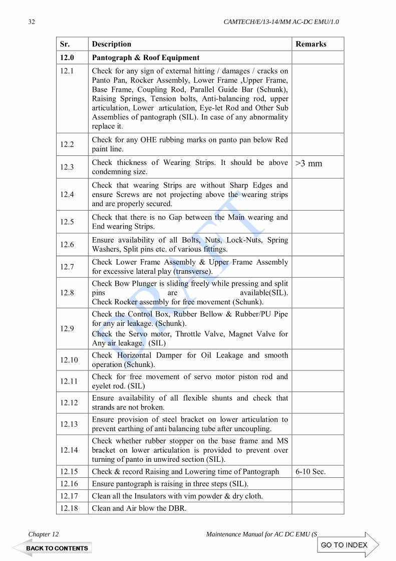
CAMTECH/E/13-14/MM AC-DC EMU/1.0
Chapter 12 Maintenance Manual for AC DC EMU (Siemens)
32
Sr. Description Remarks
12.0 Pantograph & Roof Equipment
12.1 Check for any sign of external hitting / damages / cracks on Panto Pan, Rocker Assembly, Lower Frame ,Upper Frame, Base Frame, Coupling Rod, Parallel Guide Bar (Schunk), Raising Springs, Tension bolts, Anti-balancing rod, upper articulation, Lower articulation, Eye-let Rod and Other Sub Assemblies of pantograph (SIL). In case of any abnormality replace it.
12.2 Check for any OHE rubbing marks on panto pan below Red paint line.
12.3 Check thickness of Wearing Strips. It should be above condemning size.
>3 mm
12.4 Check that wearing Strips are without Sharp Edges and ensure Screws are not projecting above the wearing strips and are properly secured.
12.5 Check that there is no Gap between the Main wearing and End wearing Strips.
12.6 Ensure availability of all Bolts, Nuts, Lock-Nuts, Spring Washers, Split pins etc. of various fittings.
12.7 Check Lower Frame Assembly & Upper Frame Assembly for excessive lateral play (transverse).
12.8 Check Bow Plunger is sliding freely while pressing and split pins are available(SIL). Check Rocker assembly for free movement (Schunk).
12.9
Check the Control Box, Rubber Bellow & Rubber/PU Pipe for any air leakage. (Schunk). Check the Servo motor, Throttle Valve, Magnet Valve for Any air leakage. (SIL)
12.10 Check Horizontal Damper for Oil Leakage and smooth operation (Schunk).
12.11 Check for free movement of servo motor piston rod and eyelet rod. (SIL)
12.12 Ensure availability of all flexible shunts and check that strands are not broken.
12.13 Ensure provision of steel bracket on lower articulation to prevent earthing of anti balancing tube after uncoupling.
12.14 Check whether rubber stopper on the base frame and MS bracket on lower articulation is provided to prevent over turning of panto in unwired section (SIL).
12.15 Check & record Raising and Lowering time of Pantograph 6-10 Sec. 12.16 Ensure pantograph is raising in three steps (SIL). 12.17 Clean all the Insulators with vim powder & dry cloth. 12.18 Clean and Air blow the DBR.

CAMTECH/E/13-14/MM AC-DC EMU/1.0
Maintenance Manual for AC-DC EMU (Siemens) Chapter 12
33
Sr. Description Remark
12.19 Visual check for any damage to grid, flashover.
12.20 Check for HT connection intactness.
12.21 Check and ensure that there is no Air Leakage from the Panto magnet valve.
12.22 Check panto tension. 10.5kg Shunk) / 9.5 kg ( SIL)
13.0 VCB
13.1 Check foundation bolts tightness.
13.2 Check the tightness Electrical connections.
13.3 Check for cracks and flash marks.
13.4 Clean the insulators.
13.5 Check for connection of AC earthing switch.
13.6 Clean and grease the AC earthing switch.
13.7 Check for any air leakage in VCB pneumatic connection.
13.8 Draining of pressure regulator and air reservoir.
14.0 DC Earthing switch
14.1 Clean & Grease the moving and fixed contact.
14.2 Ensure Connection tightness.
15.0 Change over switch
15.1 Check the HT Connection intactness.
15.2 Check the foundation bolts.
15.3 Clean insulator using Vim powder.
15.4 Check visually for any crack/ damages.
15.5 Check tightness of all cable connections.
16.0 Control and Switch Gear
16.1 Check all MCBs & Switches for normal position on the E-Cabinet in the Motor Coach.
16.2 Check for set condition of Motor Protection Switch (MPS) in all the end panels.
16.3 Testing & Calibration of compressor & Control pressure governors.
16.4 Check for any damages to ceramic parts and grid of grounding resistor.
16.5 Check the foundation for intactness.
16.6 Check the intactness of grounding shunts and provide if missing.

CAMTECH/E/13-14/MM AC-DC EMU/1.0
Chapter 12 Maintenance Manual for AC DC EMU (Siemens)
34
Sr. Description Remark
16.7 Clean and air blow the grounding resistor.
16.8 Ensure proper locking of panel doors of E-Cabinet in D/cab & MC, End wall panels other coaches.
16.9 Ensure proper position of MVB segment address selector switch.
17.0 AWS
17.1 Note the defects reported in defect card book.
17.2 Check and note the reading of SFBC, EBC, ISU.
17.3 Ensure the intactness of ISU, BAU, Indication panel, PCB card frame, Elmex terminal, magnet valve, SPM hooter & tightness of wire connections.
17.4 Check the ISU handle for proper fitment & tightened if found loose.
17.5 Ensure functioning of SPM hooter and BAU.
17.6 Check AWS MCB and ground fault.
17.7 Set wheel diameter in B4A1 card.
17.8 Function test pressure test, SPM test & simulation test to be done.
17.9 Replace speed cut off and exhaust magnet valve. 9 monthly
17.10
Check & note the Engine magnet pulses on B1A1 card by multimeter
50 Khz-socket 1 & 3 = 200 +/- 20 mv
100 Khz – socket 5 & 7 = 350 +/ - 25mv
17.11
Check voltage on B14A1 card
Socket 1-2 = 12v +/- 0.3v, 0.6v
Socket 3-2 = 24v +/- 1.1v, 0.6v
Socket 4-5 = 5v +/- 0.3v
17.12 Download Medha/ AAL SPM data
17.13
Ensure intactness of Engine magnet foundation beam, engine magnet, JB-1, JB-II, TGs, magnet valve & cover, pipes & clamping, all fasteners, washer, split spins, safety chains etc.
17.14 Check the clearance of engine magnet clearance from the rail.
17.15 Ensure TG axle attachment, dowel pins fork.
17.16 Ensure the SPM is showing speed by manually rotating TG in both directions. Ensure no brake is applied in forward direction and brake applied in reverse direction.

CAMTECH/E/13-14/MM AC-DC EMU/1.0
Maintenance Manual for AC-DC EMU (Siemens) Chapter 12
35
Sr. Description Remark
18.0 APC
18.1 Ensure proper intactness of foundation hardware of APC magnet and clearance of APC receiver from rail level.
18.2 Check for intactness of electrical coupler.
18.3 Ensure functioning of ACP receiver by passing over APC track magnet and ensure same at SIBAS clip also. Ensure reset of ACP also.
19.0 Fire Extinguisher
19.1 Check for seal intactness.
19.2 Check for refilling date & Replace if expired.
19.3 Check for fire extinguisher mounting.
19.4 Check the condition of nozzle/ pipe & replace if punctured.
20.0 PIS/PA System & TMS
20.1 Check working of intercom.
20.2 Check working of public address from both cabs.
20.3 Check working of PIS from both cabs by entering any journey.
20.4 Ensure availability of manual head code.
20.5 Check working of coach display and speakers.
21.0 Light & Fan
21.1 Check operation of Lights, Fans and Ventilation switches on 50% &100% position.
21.2 Check the working of all Fans and Lights in the coaches. Attend the defects if noticed.
21.3 Check working of Signal Bell / Emergency Bell & indication LEDs.
21.4 Check working of Flasher, Tail & Blinker Light and ensure smooth operation of their Push Buttons.
21.5 Check working of Head Light & Auxiliary Head Lights at both Dim/ Bright positions.
21.6 Check working of DC-DC Converter for Head light on both normal and standby positions.
21.7 Check head light focus and adjust if required.
21.8 Check working of Cab Light, Emergency Cab Light, Spot Light & Cab Fans.
21.9 Ensure smooth operation of all push button & switches in the D/ Cab.

CAMTECH/E/13-14/MM AC-DC EMU/1.0
Chapter 12 Maintenance Manual for AC DC EMU (Siemens)
36
Sr. Description Remark
22.0 BATTERY
22.1 Check & record Battery Voltage by operating "TEST BATTERY VOLTAGE" push button in motor coach shunting cab after switching off battery.
22.2 Check for intactness of Battery Box mounting Bracket and Bolts.
22.3 Check the battery voltage when MC charged & record it.
22.4 Check the condition of battery cover, battery box for proper fitment.
22.5 Check the condition of battery connecting leads.
22.6 Ensure intactness of lead connections.
22.7 Check the level of electrolyte in each cell &Top up if less.
22.8 Check the voltage of each cell.
22.9 Check the specific gravity of each cell.
22.10 Apply petroleum jelly on all connections after cleaning.
22.11 Clean the battery box & trolley.
22.12 Ensure proper working of trolley & door hinges.
22.13 Ensure compact placement of battery cells to avoid relative movement during run.
22.14 Clean and blowing of battery fuse box.
23.0 Final Testing from both Driving CABs
23.1 Keep MMI in Maintenance Mode
23.2 Check Healthiness of various Lamp Indication by Pushing Test Push Button.
23.3 Check on MMI that all coaches are set.
23.4
Check the Healthiness of each and every function physically which are displayed on various screens. (Top level, Unit Level, Drive/ Brake, Energy, Fault logged, V > 0 & V = 0) of MMI.
23.5 Check for any Error Message on the screen.
23.6 Check ground fault in 110V DC and 110V AC circuit by multimeter. Record voltage between (45 - 55 V), + ve to ground, -ve to ground.
23.7 Check CB set/ trip on MMI.
23.8 Check Panto Raising/Lowering timing on MMI. 6-10 Sec
23.9 Check working of Fan, Light and Ventilation (both 50% and 100%).
23.10 Check Changeover on MMI for 415V AC, 110V AC, 110V DC by operating Basic Unit Isolating Switch.

CAMTECH/E/13-14/MM AC-DC EMU/1.0
Maintenance Manual for AC-DC EMU (Siemens) Chapter 12
37
Sr. Description Remark
23.11 Check operation of Head Light, Auxiliary Head Light , Flasher, Tail Light and Blinker Light.
23.12 Check operation of Signal bell and Emergency bells and their indication.
23.13 Check working of PA/ PIS.
23.14 Check for Healthiness of Head-code.
23.15 Check functionality of Entering Neutral Section Push Button by observing feed-back on SKS 12 & 13.
23.16 Check operation of "Battery Supply" switch.
23.17 Check working of Emergency OFF Loop push Button.
23.18 Ensure AWS working by Pressing vigilance Push button for 8 sec.
23.19 Check working of Dead man valve in normal and RDM mode.
23.20 Measure and record the rate of air flow of ACU & TCU blowers of all four Motor coaches.
ACU >5-6 m/s TCU >7-9 m/s
23.21 Check working of audio visual and cross passing.
23.22 Run down the Rake in Normal and RDM mode from both cabs.
23.23 Check AWS Speedometer and Speed Recorder and ensure no differential error in both cabs.
23.24 Revert MMI to "Drive Mode" after completion of testing.

CAMTECH/E/13-14/MM AC-DC EMU/1.0
Chapter 12 Maintenance Manual for AC DC EMU (Siemens)
38
12.8 MAINTENANCE SCHEDULE OF AC-DC (Siemens) IC (180Days) CARRIAGE
S.N. Items to be checked Remark
1.0 Driving-CAB
1.1 Check proper working of Duplex, BC, Guard's and Parking Brake gauges.
1.2 Check for availability of Wooden Wedges. 04 nos.
1.3 Check for availability of Fire Extinguishers. 02 nos.
1.4 Ensure cleaning of look out glasses (M/Man side & Guard side).
1.5 Ensure cleaning of D/cab & Driver Desk
1.6 Check for smooth operation of guard emergency handle and proper ON/OFF stenciling
1.7 Check for any air leakage from pipe & couplings of Guard emergency handle.
a. Check while the rake is rolling:
1. Check skidding of wheels.
2. Check unusual noise from under-gear.
b. On Stationary mode:
1. Check logbook and enter remarks regarding attention against any adverse remarks given logbook.
2. Check the function on MMI for all coaches.
3. Check brake continuity test.
4. Check Signal bell – I continuity.
5. Check Signal bell – II continuity
6. Check working of intercom and PA system.
7. Check working of AWS.
2.0 ACP
2.1 Check working of ACP by pulling handle from each coach (east & west side) and ensure flag is coming out sufficiently and getting reset.
2.2 Ensure that coach in which ACP operated is correctly displayed on the MMI.
2.3 Overhauling and lubrication of ACP mechanism.
3.0 Air Spring Suspension
3.1 Check the foundation allen bolts intactness.
3.2 Check air spring for any cracks, dent marks. leakages and hitting marks on air spring.

CAMTECH/E/13-14/MM AC-DC EMU/1.0
Maintenance Manual for AC-DC EMU (Siemens) Chapter 12
39
Sr. No. Items to be checked Remark
3.3 Check the foundation and fitment of vertical dampers & Replace if not working.
3.4 Check the Leveling Valve assembly for any leakage & Replace if required.
3.5 Check the Installation lever and adjust the clearances if found abnormal.
3.6 Check the working of all cocks provided for air spring & Replace if required.
3.7 Ensure that Leveling Valve installation Rod is in vertical position.
3.8 Ensure proper position of all air springs cocks. 3.9 Drain Air Spring Reservoir and ensure availability of
baffle plates to protect drain cock.
3.10 Check all the Pipes & Couplings for any air leakages and attend it.
3.11 Check for any rubbing / air leakage/ damage to the air spring flexible hoses and replace if required.
3.12 Ensure availability & intactness of bolster liner locking plate.
3.13 Check the welded joints of Air spring base frame for any crack/ breakages.
3.14 Check the intactness of foundation bolts of 20 ltrs. tank and healthiness of release valve.
3.15 Check the function of duplex check valve as per work instructions.
3.16 Ensure the foundation bolt intactness of leveling valve protection plate.
4.0 Air Drier 4.1 Check for intactness of mounting hardware. 4.2 Check for any air leakage from Duplex piston valve. 4.3 Purging of air dryer with interval of 120 secs. 4.4 Check for alternate operation of regenerative towers.
4.5 Check the healthiness of desiccant by observing colour of humidity indicator.
Blue = OK, Yellow = warning
4.6 Check and observe the water content in MR by dew point meter.
4.7 Visual inspection for external damages to air dryer and its pipe lines.
4.8 Check the tightness of Electrical supply connector.

CAMTECH/E/13-14/MM AC-DC EMU/1.0
Chapter 12 Maintenance Manual for AC DC EMU (Siemens)
40
Sr. No. Items to be checked Remark
5.0 Parking Brake
5.1 Check for proper fitment of Parking Brake Cylinder foundation, Brake Arm, Cup Sleeve, Release handle wire rope etc.
5.2 Check the Parking Brake Cylinders operation, (wheel No. 1-3, 5-7 in DTC and middle NDTC) and ensure physically application and release of the brakes.
5.3 Check the working of Double Check Magnet valve. Replace If found leakage / not working.
5.4 Ensure the intactness of Double Check Magnet valve foundation allen bolts.
5.5 Ensure releasing of brakes with rope handle.
6.0 Buffers & Schaku Coupler
61 Ensure the intactness of Cup-Sleeve Bolt.
6.2 Check for any air leakage from MR & BP Pipe bracket, bushing, V holding and Elbow clamps,
6.3 Check the condition of centering device & leaf spring.
6.4 Check greasing of articulation bearing bolt and condition of bush.
6.5 Clean and lubricate coupler articulation bearing bolt and fiber bush.
6.6 Measure and ensure bogie clearances.
6.7 Check Front screw coupling for any abnormality, lubricate if required.
6.8 Check intactness of couplers, earthing cables.
6.9 Check draw bar and allen key bolt for proper tightness.
6.10 Check the tightness of check nut and wing nut.
7.0 Piping & Reservoirs
7.1 Check for any air leakage/ rubbing & ensure availability of clamps.
7.2 Check welding joints, split pins, fixing bolts of all the reservoirs.
7.3 Check for any isolation of EP/ AUTO/ Bogie & coupling cocks and attend if isolated.
7.4 Ensure smooth operation of EP, Auto & Bogie cocks.
7.5 Ensure that bogie cocks are vent type, if found without vent same to be replaced.
7.6 Ensure EP and Auto cocks are without vent type.

CAMTECH/E/13-14/MM AC-DC EMU/1.0
Maintenance Manual for AC-DC EMU (Siemens) Chapter 12
41
Sr. N. Items to be checked Remark
7.7 Check for any Damage to Piping and Cocks & Replace defective / leaking cocks.
7.8 Check intactness of foundation Bolts of MR, Auxiliary and Air Spring Reservoirs & Ensure availability of split pins.
7.9 Check the intactness of Reservoirs MS straps.
7.10 Drain all the Reservoirs with drain cocks.
7.11 Check the operation of MR, BP, Bogie isolating and drain cocks & Replace if any leakage.
7.12 Check for leakage of flexible hoses.
7.13 Observe any sign of air leakage and looseness of end fittings.
7.14 Check rubbing of hose pipes and shifting of end nipples.
7.15 Check MR/BP cocks leakage by closing cocks.
7.16 Ensure cleaning of NRV and pipe line strainers.
8.0 BOGIE
8.1 Check Bogie frame, Bolster and coach under-frame for any crack / damages or excessive wear.
8.2 Check coach sole bar and under frame for any cracks / hitting marks.
8.3 Check condition of liner between Bogie & Bolster.
8.4 Check for healthiness and foundation intactness of lateral and vertical friction dampers. Check for signs of oil leakages.
8.5 Check Palm-pull rods for any crack / bend.
8.6 Check condition of bushes, pins and safety Chains.
8.7 Check availability of pins with Bulb Cotters & Split Pins.
8.8 Check Side Bearer for Crack or Oil Leakage.
8.9 Check for Side Bearer cover jam / loose.
8.10 Check and ensure the intactness of Cattle guard, Buffer foundation Bolts.
8.11 Check for hitting/rubbing between bolster and bogie in lateral direction. Check for condition of liner plate and proper clearance.
< 3mm
8.12 Check brake shoe hanger assembly for any excessive play, crack & damages.
8.13 Check intactness of rubber snubbers and crown packing on axle box.

CAMTECH/E/13-14/MM AC-DC EMU/1.0
Chapter 12 Maintenance Manual for AC DC EMU (Siemens)
42
Sr. N. Items to be checked Remark
8.14 Check for any damage or abnormality on brake yoke assembly.
8.15 Check the condition of safety brackets and intactness of fixing bolt.
8.16 Check height of cattle guard from rail level. 150 to200 mm
9.0 BRAKE CYLINDER
9.1 Check fixing Bolts of Brake Cylinders for any damage or slackness.
9.2 Check Brake Rigging parts i.e. pins, Nut Bolts, Cutters, Split Pins, Brake Block key, Brake shoe head pins for missing, worn out, slackness.
9.3 Check Brake Hanger Safety Brackets and Safety Stopper Plates are intact.
9.4 Replace worn out Brake Blocks.
9.5 Check Brake Cylinder Piston not infringing with U Bracket in brake applied condition.
10.0 BRAKE BLOCK
10.1 Adjust gap between brake blocks and wheel in released condition.
12 mm to 15 mm
10.2 Ensure tightness of brake shoe key.
11.0 BRAKE RIGGING
11.1 Check Nuts, Bolts, Pins, Cotters, Bush, and Washers for intactness and wear, replace if required.
11.2 Ensure availability of Stopper Plates.
11.3 Check Brake Hangers, Brake Beams and other Brake Rigging components for intactness and wear.
11.4 Lubricate all the moving parts by applying oil / grease.
12.0 DASHPOT
12.1 Check the oil level, top up if required. Record the quantity of oil topped up in Dash pot.
MC 97 mm
12.2 Check DashPot bottom rubber packing for torn & damage.
12.3 Check intactness of dashpot safety loop brackets. Ensure intactness of oil filling nipples / cap.
13.0 WHEEL & AXLE BOX
13.1 Check for tilting of Axle Box.
13.2 Check Wheel with tapping hammer for any dull sound, intactness of keys and glut ring, crack, flow of metal at surface.
on tyred wheels

CAMTECH/E/13-14/MM AC-DC EMU/1.0
Maintenance Manual for AC-DC EMU (Siemens) Chapter 12
43
Sr. N. Items to be checked Remark
13.3 Check and record the wheel size.
13.4 Check Axle Box cover for any crack and grease leakage.
13.5 Check Axle Box Covers for intactness of bolts and availability of Split Pins.
13.6 Check the Wheel for Flat, Chipping and other defects.
13.7 Take Wheel profile and check for wheel defect such as shell tread, Grooved / Flat tyre, Sharp flanges, Deep Flanges, Thin Flanges, Root Wear & other defects.
13.8 Visually check for any abnormality like disc shifting Axles, MSUs etc.
13.9 Check the temperature of Axle boxes with the help of temperature gun.
While rake is placed in shed
14.0 FURNISHING ITEMS
14.1 Ensure healthiness of both side curtains and V-Cool films in both D-Cabs.
14.2 Check M/man seat for smooth up/down and Forward/ Reverse movement operation.
14.3 Check Grab Handles and Center Pole for proper intactness and welding & Provide missing grab handles.
14.4 Check operation (open/close/locking) of D/cab doors and windows.
14.5 Check operation (open/close/locking) of doors in passenger area / check for any damages.
14.6 Check the seats for any damage and foundation bolt intactness. Attend broken Seats & Seat Frames and torn first class seats.
14.7 Ensure availability of safety cover of Articulation Bearing bolt.
14.8 Check in Handicap compartment for passenger amenities.
14.9 Clean the drain holes on the flooring in passenger area.
14.10 Check the interior & exterior stenciling of coach.
14.11 Ensure intactness of Door way side partition foundations.
14.12 Ensure intactness Coach body end panel partition.
14.13 Ensure intactness Partition SS sheet welding and molding screw.
14.14 Ensure intactness of the hatch door bracket welding from inside
14.15 Ensure intactness of hatch door nut and bolt from inside.

CAMTECH/E/13-14/MM AC-DC EMU/1.0
Chapter 12 Maintenance Manual for AC DC EMU (Siemens)
44
Sr. N. Items to be checked Remark
14.16 Ensure intactness of hatch door screw from outside.
14.17 Ensure intactness of hatch door fixing chain and clamp inside the HT compartment.
15.0 TESTING
15.1 Put MMI in maintenance mode & Switch on DCS and observe on MMI.
i) Applica./tion of holding brakes in all coaches.
ii) DCS key “ON” position 0.8 Kg/cm2
iii) DCS key “OFF” position 1.2 Kg/cm2
15.2 EP Brake Application
i) Application Timing 4-6 sec
ii) Release Timing 4-6 sec
15.3 Auto Brake Application
i) Application Timing 6-10 Sec
ii) Release Timing 10-15 sec
15.4 Emergency brake with Power Brake Controller
i) Application Timing 4-6Sec
ii) Release Timing 10-15 sec
15.5 Emergency brake with Pneumatic Brake Controller
i) Application Timing 6-10 Sec
ii) Release Timing 10-15 sec
iii) Check EP application and releasing time.
iv) Check Auto application and releasing time.
15.6 Check Emergency application and releasing time.
15.7 Check working of Brake Controller at all positions & Ensure No leakage from Brake Controller in release / auto lap position.
15.8 Ensure No air leakage from EP unit in both released and applied condition.
15.9 Ensure no EP Unit should be Hunting.
15.10 Ensure the provision of safety valve in all brake units.
15.11 Ensure the functioning of Brake Unit Safety Valve by applying Auto Brake .
15.12 Ensure functioning of Emergency Valve in normal and RDM.
15.13 Ensure functioning of Guards Emergency Brake.
15.14 Check all Brake Cylinders for Leakage.

CAMTECH/E/13-14/MM AC-DC EMU/1.0
Maintenance Manual for AC-DC EMU (Siemens) Chapter 12
45
Sr. No. Items to be checked Remark
16.0 PNEUMATIC TESTING
16.1 Check BP pressure charging time from both cab 0 to 4.7 kg/cm2.
2.5 to 3 minutes for 12 car rake
16.2 Measure brake pipe pressure on Duplex gauge.
i)
Pre-Testing Final Testing ICS ON Cab-1 BP Cab-1_______ BP Cab-1_______ BP Cab-2 _______ BP Cab-2_______ * Pressure difference in both Cab's RDK should not be
> 0.1kg/cm2
ii)
Pre-Testing Final Testing ICS ON Cab-2 BP Cab-1_______ BP Cab-1_______ BP Cab-2 _______ BP Cab-2_______
16.3 Check 1.0 kg/cm2 MR pressure dropping time. 10 minutes
16.4 Check 1.0 kg/cm2 BP pressure dropping time. 10 minutes
16.5 Check MR and BP drop test in 10 minutes, <1.0 kg/cm2.
16.6 Ensure MR and BP pipe pressure continuity.
16.7 Ensure proper working of Duplex Pressure Gauge, BC Gauge, Parking Brake and Guard's Gauge.
16.8 Ensure physically application & release of Parking Brake and on MMI.
16.9 Ensure Parking Brake gauge shows 0.0 kg/cm2 pressure in applied condition and 5 kg/cm2 in released condition.
16.10 Ensure the working of Parking Brake Push button.
16.11 Ensure smooth operation of Horn Foot Valve.
16.12 Ensure quality sound of horns.
16.13 Ensure correct position of check nut in Escort make ICS.

CAMTECH/E/13-14/MM AC-DC EMU/1.0
Chapter 12 Maintenance Manual for AC DC EMU (Siemens)
46
12.9 POH SCHEDULE FOR AC/DC SIEMENS EMU RAKES
Sr. No. Description Std
Parameters POH
(18 Months) 1.0 DRIVING-CABS
1.1 Check & ensure smooth operation of all push buttons (DVR desk) and replace if required. Ensure provision of all the labels.
OK YES
1.2 Entering neutral section (ENS) (Condition basis)
OK YES
(i) Light set / trip.(Condition basis) OK YES
(ii) Fan set / trip.(Condition basis) OK YES
(iii) SB1-100% replacement. OK YES
(iv) Check operation of all switches (E-cabinet & DVR desk) & replace if required. Ensure provision of all the labels.
OK YES
1.3 Pan UP & Down (Condition basis). OK YES
(i) MC ON & OFF switches replacement to be done 100%.
OK YES
(ii) Calibration and testing of AWS speedometer, Techo Generator and speed Recorder with Techo Generator.
Done YES
1.4 Check condition of all MCB's (E-cabinet). Done YES
1.5 Replace defective indication LEDs, MCBs, rotary switches & push buttons.
Done YES
1.6 Check for availability of labels on E-cabinet, Provide missing labels.
1.7 Clean and overhaul cab fans, Replace carbon brush.
Done YES
1.8 Calibrate all pressure gauges (guard gauge, Duplex gauge, PB & BC)
Done YES
1.9 Clean the drivers desk area and under the desk with vacuum cleaner.
Done YES
1.10 Clean Cab light Reflectors. Done YES
1.11 Change the lamps of head light, Aux head light and cab light.
Done YES
1.12 Check the working of spot light. OK YES
1.13 Check the working flasher light in both normal & standby mode.
OK YES
1.14 Check the working of H/L & S/L both in normal & standby mode.
OK YES

CAMTECH/E/13-14/MM AC-DC EMU/1.0
Maintenance Manual for AC-DC EMU (Siemens) Chapter 12
47
Sr. No. Description Std
Parameters POH
(18 Months) 2.0 MASTER CONTROLLER
2.1 Check operation of Master Controller and lubricate the cam switches as per OEM instruction.
OK YES
2.2 Replace the defective Micro switches / cams if any and ensure proper tightness of fasteners as per specified torque.
OK YES
2.3 Visual check all electrical connections and their intactness.
OK YES
2.4 Ensure that dead man valve operates at specified angle.
OK YES
2.5 Ensure that "T" handle is not loose and there is no excessive play.
OK YES
2.6 Overhauling of master controller & testing on endurance test bench.
OK 2nd POH
3.0 MMI
3.1 Functional test of MMI. Done YES
3.2 Ensure working of MMI cooling fan. Clean the fan.
Done YES
4.0 COACH LIGHTS
4.1 Ensure working of all tube lights and emergency lights. Replace defective fittings.
OK YES
4.2 Clean all the reflectors of coach lights. OK YES
4.3 Replace the reflector frame air tight gaskets if required.
OK YES
4.4 Ensure setting and tripping of light from both D/cabs.
OK YES
4.5 Replace tube lights (Condition basis) OK 2nd POH
4.6 Replace 100% electronic ballasts (Condition basis )
OK 2nd POH
5.0 FANS
5.1 Clean the fans, replace defective guards and blades.
OK YES
5.2 Ensure 100% of working fans. OK YES
5.3 Check availability and tightness of all fixing, cover and guard.
OK YES
5.4 Replacement of capacitor of carriage fans. OK 2nd POH
5.5 Ensure noise free running, replace Bearings if required.
OK YES

CAMTECH/E/13-14/MM AC-DC EMU/1.0
Chapter 12 Maintenance Manual for AC DC EMU (Siemens)
48
Sr. No. Description Std
Parameters POH
(18 Months) 6.0 END PANELS
6.1 Open and blow out the dust. Done YES
6.2 Clean the terminals with Nylon brush. Done YES
6.3 Check the tightness of connection in the train line junction box.
Done YES
6.4 Check condition of lugs, sleeves & number ferrules.
OK YES
6.5 Check the operation of all MCB's. Replace defective MCBs.
Done YES
6.6 Check & ensure the tightness of 415 v three phase connections and terminals.
OK YES
6.7 Visually check and ensure the operation of light /fan contactor, change over contactor, MAC contactor. Replace if tips are found flashed. Ensure provision of all the labels.
OK YES
6.8 Check the operation and function of all motor protection switches (MPS). Replace defective switches.
OK YES
7.0 PNEUMATICS & BRAKES
7.1 Overhaul and test of all Brake Equipment. Done YES
7.2 Over haul & test Dead-man magnet valve, AWS Feed Cut- Off Valve, Exhaust Valve and Emergency Valves.
Done YES
7.3 Overhaul Non Return Valves. Done YES
7.4 Replace damaged / leaking drain cocks. OK YES
7.5 Overhaul & test Brake Cylinders. OK YES
7.6 Check condition of MR, BP hoses & replace if defective.
OK YES
7.7 100 % replacement of MR, BP flexible hoses. NA 4th POH
7.8 Calibrate all the pressure governor.
A) Control Governor 3.4 to 4.2 kg/cm2.
YES
B) Equipment Governor 4.6 to 5.6 kg/cm2
YES
C) Main Comp Governor 6.0 to 7.0 kg/cm2
YES
D) Aux Comp Governor 5.3 to 6.3 kg/cm2
YES
E) Parking Brake Governor 2.0 to 3.0 YES

CAMTECH/E/13-14/MM AC-DC EMU/1.0
Maintenance Manual for AC-DC EMU (Siemens) Chapter 12
49
Sr. No. Description Std
Parameters POH
(18 Months) kg/cm2
7.9 Overhaul all the strainers and filters & Replace rubber items.
Done YES
7.10 100% Replacement of filter elements. Done 4th POH
7.11 Check operation and lubricate isolating cocks. Replace defective cocks.
OK YES
7.12 Overhaul Auto Drain Valves. Done YES
7.13 Overhaul Panto Set-Trip Magnet Valves. Done YES
7.14 Overhaul Panto Isolating Cock and Throttle Valves.
OK YES
8.0 PIPING & RESORVOIERS
8.1 Check the welding joints, split pins, fixing bolts of MR, Aux. and Air spring reservoirs for intactness.
OK YES
8.2 Check the intactness of MS straps of all the reservoirs.
Done YES
8.3 Check for hitting marks and attend if any. Done YES
8.4 Ensure that the pipes are not rubbing with coach body or bogie frame etc.
Done YES
8.5 Ensure the availability of Baffle protection plates for drain cocks to arrest damage due to ballast hitting.
Done YES
8.6 Check the availability of proper pipe line clamps as per the ICF Drg.
Done YES
8.7 Pressure testing of reservoir at 10 Kg/cm2 Done 2nd POH
9.0 GUARDS EMERGENCY BRAKES
9.1 Overhaul Guard Emergency brake valve and ensure its smooth operation.
OK YES
9.2 Ensure that the handle "ON-OFF" position is proper.
OK YES
10.0 PARKING BRAKES
10.1 Overhaul the parking brake cylinder, Double check magnet valves & pressure reducing valve.
Done YES
10.2 Check for proper fitment of parking brake cylinder, brake arm, cup sleeve and release handle etc.
Done YES
10.3 Check parking brake operation on wheel no.1,3, 5&7 in 'C' coaches. Verify application and release of the brakes.
Done YES

CAMTECH/E/13-14/MM AC-DC EMU/1.0
Chapter 12 Maintenance Manual for AC DC EMU (Siemens)
50
Sr. No. Description Std
Parameters POH
(18 Months) 11.0 SHUNTING CAB
11.1 Check smooth operation of all switches & push button and ensure healthiness of indication lamps.
OK YES
11.2 Check the working of Battery Selector Switch. OK YES
11.3 Check for smooth working of master controller. OK YES
11.4 Check the working of Shunting Cab Gauges & Meters.
OK YES
11.5 Clean the Shunting Cab area and under the desk with Vacuum Cleaner.
OK YES
11.6 Check the condition of flexible hoses of pantograph, changeover switch and VCB. Replace if found defective.
OK YES
11.7 100 % replacement of all the hoses. Done 4th POH
12.0 MAIN COMPRESSOR
12.1 Clean externally compressor body & the radiator.
OK YES
12.2 Replace air suction filters. Done YES
12.3 Check the condition of drain plug for sticking up of metal particles.
Done YES
12.4 Check condition of top and bottom Rubber Gaskets. Replace if found defective.
Done YES
12.5 Check for any oil or air leakage from joints, suction or delivery pipes and attend.
Done YES
12.6 Overhaul and calibrate safety valve setting. 8.5 Kg/cm2 YES
12.7 Check condition of resilient mounting for intactness.
OK YES
12.8 Check for any crack/intactness of base frame. OK YES
12.9 Check vacuum indicator on silencer (suction filter) i)Colourless-ok ii) Red Colour - Suction filter defective
OK YES
12.10 Replace lubricating oil. OK YES
12.11 Ensures availability all fasteners. OK YES
12.12 Ensure proper tightness of delivery pipe. OK YES
12.13 Ensure the healthiness of mounting wire ropes. OK YES
12.14 Overhaul the Resilient mounts. OK 2nd POH
12.15 Check operation of compressor by way of observing running sound, feel temperature by
OK YES

CAMTECH/E/13-14/MM AC-DC EMU/1.0
Maintenance Manual for AC-DC EMU (Siemens) Chapter 12
51
Sr. No. Description Std
Parameters POH
(18 Months) hand.
12.16 Remove and Overhaul as per OEM manual. OK 4th POH (Knorr) 2nd POH (ELGI)
12.17 Check pressure built up time of each Unit (0- 7 kg/cm2).
6 minutes YES
13.0 AUXILIARY COMPRESSOR
13.1 Replace lubricating oil. Done YES
13.2 Clean externally including the surrounding area. Done YES
13.3 Replace suction filter. Done YES
13.4 Check the tightness of foundation bolts and other fasteners.
Done YES
13.5 Clean the commutator with compressed air/ Charmis leather & replace the carbon brushes.
Done YES
13.6 After maintenance carry out an efficiency test. Record pressure build up time from 0 to 5.0 kg/cm2
4 minutes YES
13.7 Check operation of compressor by way of observing running sound and temperature.
OK YES
13.8 Ensure air blowing of pipe lines connected to Aux. compressor.
Done YES
13.9 Overhaul NRV & ' T' Strainer. Done YES
13.10 Overhaul and calibrate safety valve. OK YES
13.11 Remove and overhaul as per OEM manual Done 2nd POH
14.0 AIR DRIER
14.1 Check mounting arrangement of Air Drier for intactness.
OK YES
14.2 Overhaul the Duplex Piston Valve and Replace all "O"rings.
OK YES
14.3 Replace final filter element. OK YES
14.4 Check for any leakage from Air Drier. OK YES
14.5 Check proper working of air dryer as under; a) Purging of air dryer with interval of 120 sec. b) Check the alternate operation of cooling towers. c) Check the healthiness of desiccant by observing colour indicator (Blue = OK, Yellow = warning, Red = Not OK)
Done YES

CAMTECH/E/13-14/MM AC-DC EMU/1.0
Chapter 12 Maintenance Manual for AC DC EMU (Siemens)
52
Sr. No. Description Std
Parameters POH
(18 Months) 14.6 Overhaul as per OEM's Manual. Done YES
15.0 BATTERY
15.1 Clean and Overhaul Battery set as per OEM’s manual
Done YES
15.2 Clean the battery box & trolley OK YES
15.3 Ensure proper working of trolley the door hinges.
OK YES
15.4 Ensure compact placement of battery cells to avoid relative movement during run.
OK YES
15.5 Change the battery set with new one every 4.5 years (54 months).
Done 3rd POH
16.0 AC-DC EARTHING SWITCH
16.1 Check the condition of moving & fixed contact and locking mechanism.
OK YES
16.2 Check AC & DC Earthing Switch for smooth operation and intactness.
OK YES
16.3 Check of Kaba keys. OK YES
16.4 Overhaul the switch as per OEM's manual. OK 4th POH
16.5 Check for intactness of copper flexible braids & earthing shunts. Replace if found broken / flashed.
OK YES
17.0 TRANSFORMER
17.1 Ensure the oil level in transformer. Check for any oil leakage. Top up if required.
OK YES
17.2 Check transformer for hitting or damage to any part.
No hitting / damage
YES
17.3 Check condition of HV Cable Head Bushing for tightness.
OK YES
17.4 Check silica gel for any colour change Heat/ replace if required.
Orange YES
17.5 Clean radiator with dry compressed air. Done YES
17.6 Clean transformer with dry compressed air. Done YES
17.7 Check transformer oil pump for any leakage & abnormal sound.
No leakage YES
17.8 Check BDV of the transformer oil. Filtration to be done if required.
50 kV YES
17.9 Conduct test on oil samples as per OEM manual.
OK YES
17.10 Ensure the healthiness of sensors and their OK YES

CAMTECH/E/13-14/MM AC-DC EMU/1.0
Maintenance Manual for AC-DC EMU (Siemens) Chapter 12
53
Sr. No. Description Std
Parameters POH
(18 Months) wiring.
17.11 Check the healthiness of radiator fans and ensure proper direction of rotation.
OK YES
17.12 Check IR of primary and secondary winding. OK YES
17.13 Check for proper functioning of Oil flow, oil level and temperature sensors.
OK YES
17.14 Ensure the healthiness of pressure relief valve. OK YES
17.15 Ensure the healthiness of oil level indicator (Visual glass type).
OK YES
17.16 Overhaul the Resilient mounts. Done 2nd POH
18.0 CABLE HEAD TERMINATION ( CHT )
18.1 Check and clean the bushing & ensure its healthiness.
Done YES
18.2 Check intactness HV bushing clamps in under-frame and on roof.
OK YES
18.3 Replace CHT. Done 8th POH
19.0 TRACTION MOTOR
19.1 Visual inspection for any damage or rubbing. OK YES
19.2 Ensure intactness of all the Fasteners. OK YES
19.3 Check Earthing brush (ERB) assembly. Replace Brush If found half worn.
OK YES
19.4 Check intactness of body earthing. OK YES
19.5 Check the condition of Air below / duct for any damage and intactness of all fasteners.
OK YES
19.6 Clean suction air filters by dry compressed air. Done YES
19.7 100% replacement of suction filters. Done Every POH
19.8 Open junction box and check for connection tightness, flashing or overheating marks.
Done YES
19.9 Clean the metal particles from the magnetic oil drain screw on gear case.
OK YES
19.10 Blow TM with the help of dry compressed air. Done YES
19.11 Re-grease the motor bearing (N-End) Shell Retinax LX2 (H3 17) Qty. 26 Gms.
Done YES
19.12 Change the Gear Oil after cleaning the Gear Case internally.
Done YES
19.13 Ensure proper Cleating and Routing of TM cables.
Done YES
19.14 Check IR and continuity of stator winding. Done YES

CAMTECH/E/13-14/MM AC-DC EMU/1.0
Chapter 12 Maintenance Manual for AC DC EMU (Siemens)
54
Sr. No. Description Std
Parameters POH
(18 Months) 19.15 Check the winding resistance with DLRO. Done YES
19.16 Check pinion teeth for any dent / pitting marks or wear.
Done YES
19.17 Replace the hard ware items, gaskets, felts and sealants of gear-case.
Done YES
19.18 Check the lugs for proper crimping and over-heating marks.
Done YES
19.19 Check for proper intactness of cable screen earthing near cable ground.
Done YES
19.20 Check the condition of bearing by Shock pulse meter.
Done YES
19.21 Assemble the motor on bogie and green run test in both direction for 2 Hrs.
Done YES
19.22 Check for any oil leakage or abnormal sound from TM and MSU and record temperature rise of DE & NDE TM & MSU bearings.
OK YES
19.23 Light run motor at rated speed and ensure bearing testing by SPM/vibration meter.
OK YES
19.24 Complete Overhaul the traction motor. OK 8th POH
20.0 MOTOR SUSPENSION TUBE UNIT (MSU)
20.1 Check housing bolts are intact. OK YES
20.2 Check for proper fitment of adjustment washer. OK YES
20.3 Check for any cracks or damage to MSU. OK YES
20.4 Topping of bearing grease by Shell Retimax LX2 (H3 17) Qty. 300grms.
OK YES
20.5 Dismantle MSU and overhaul as per OEM's manual.
Done 4th POH
21.0 High Speed Circuit Breaker (HSCB)
21.1 Visually check for any damage etc. OK YES
21.2 Clean the arc-chute horn. OK YES
21.3 Check surface finish of contacts for pitting / flashing marks.
OK YES
21.4 Measure contact wear. Replace worn out contacts.
OK YES
21.5 Check condition of Inrush resistance. Measure variation.
OK YES
21.6 Replace of main contacts, arc chutes & closing device components.
OK 2nd POH
21.7 Dismantle and Overhaul as per OEM's manual. OK 4th POH

CAMTECH/E/13-14/MM AC-DC EMU/1.0
Maintenance Manual for AC-DC EMU (Siemens) Chapter 12
55
Sr. No. Description Std
Parameters POH
(18 Months) 22.0 CONTACTORS (K1 & K4, K5 & K6)
22.1 Clean magnetic core and insulating parts by compressed air.
Done YES
22.2 Check the surface of electromagnet and clean with alcohol if needed.
OK YES
22.3 Check the condition of Main & Auxiliary Contacts.
OK YES
22.4 Check the condition of arc-chutes. OK YES
22.5 Check for smooth closing of magnet valve without jamming at 55% Ve.
OK YES
22.6 Check that the two poles of contactor closes simultaneously.
OK YES
22.7 Check the wear of main and aux. contacts. Replace worn out contacts.
OK YES
22.8 Check value of pre charging resistors. OK YES
22.9 Dismantle and Overhaul as per OEM's manual. Done 4th POH
23.0 VCB
23.1 Check for any damage and tightness of connectors and magnet valve coil.
OK YES
23.2 Check for crack, chip and flash mark on insulators.
OK YES
23.3 Clean the insulator with dry and clean cloth. OK YES
23.4 Check for damage to connection to earthing isolator. Cleaning and greasing if required.
Done YES
23.5 Check HV connection tightness. Done YES
23.6 Check torque of VCB fixing screw. 70Nm torque
YES
23.7 Check the earth connection tightness. 70Nm torque
YES
23.8 Check & set value of pressure regulator. 4.5±0.1 kg/cm2
YES
23.9 Drain air reservoir tank. Done YES
23.10 Check for any air leakage in VCB. Done YES
23.11 Check the cable and lugs for breakage & looseness of auxiliary switch.
Done YES
23.12 Check the working order of each auxiliary switch.
Done YES
23.13 Check auxiliary switch screw for damage. Done YES

CAMTECH/E/13-14/MM AC-DC EMU/1.0
Chapter 12 Maintenance Manual for AC DC EMU (Siemens)
56
Sr. No. Description Std
Parameters POH
(18 Months) 23.14 Check auxiliary switch moving contact for its
continuity OK YES
23.15 Securing of auxiliary switch and support plate. OK YES
23.16 Check proper fixing/sticking of shock absorber plate in cylinder mounting plate.
OK YES
23.17 Check setting of pressure switch. Done YES
23.18 Check the tightness of pneumatic connection of pressure switch.
Done YES
23.19 Check the contact spring. Done YES
23.20 Weight the air dryer, if increase in weight is more than 0.8 kg from new weight, regenerate molecular sieve by heating and replace if required.
Done YES
23.21 Check the healthiness of EP valve coil résistance (1510Ω ± 8 at 35° C).
Done YES
23.22 Check the air leakage from piston assembly. OK YES
23.23 Replacement of filter cartridge with `O' ring of pressure regulator.
OK YES
23.24 Check the closing and opening speed. OK YES
23.25 Check the sealing connectors, Flexible Pipe, regulators, air tank etc.
OK NA
23.26 Lubricate drive plate assembly, shafting head bearing guides, vertical spring, flexible braids, piston seal, piston rod & EP valve.
OK YES
23.27 Torque tightening - 1) rear flange, 19.3 NM YES
2) Shafting head 193NM YES
3) Vertical insulator 67NM YES
4) Bolts of cover for holding cylinder
67NM YES
5) air tank mounting nuts
39.4NM YES
23.28 Inspection of main contacts wear in vacuum switch tube.
OK YES
23.29 Overhaul the VCB as per OEM's instruction and RDSO SMI.
Done YES
24.0 BRAKING RESISTOR
24.1 Visual check for any damage to grid, flashover. OK YES
24.2 Air Blowing /cleaning by water jet to be done of OK YES

CAMTECH/E/13-14/MM AC-DC EMU/1.0
Maintenance Manual for AC-DC EMU (Siemens) Chapter 12
57
Sr. No. Description Std
Parameters POH
(18 Months) entire unit.
24.3 Check for HT connection intactness. OK YES
24.4 Spray cleaning solution on the resistor after removing the cover and terminal box from housing and wash by using water jet and dry it with compressed air. Note: cleaning should be done only after cooling of resistors
OK YES
24.5 Check the ceramic parts if show sign of damage to be replaced.
Done YES
24.6 Dismantle and Overhaul as per OEM's manual. Done 4th POH
25.0 L.A., C.T. & P.T.
25.1 Check for any abnormality Clean the insulators. OK YES
25.2 Check IR continuity. OK YES
25.3 Check the cable connections and tightness. OK YES
25.4 Check & replace the PT secondary fuse if required.
OK YES
26.0 PANTOGRAPH (ROOF EQUIPMENT)
A M/s SCHUNK
26.1 Replacement the rubber/ PVC air pipe. OK YES
26.2 Replacements of air bellow if any air leakage. OK YES
26.3 Check & adjust the static contact force. OK YES
26.4 Check the setting of control box Safety Valve. 10.5Kg/cm2 YES
26.5 Replacement of defective lock of pneumatic control Box
12.5 kg/cm2 YES
26.6 Check the intactness all fasteners and ensure tightness as per specified torque in OEM manual.
OK YES
26.7 Clean the mounting insulators with VIM powder.
OK YES
26.8 Replacement of flexible copper shunts if more than 25% strands are broken
OK YES
26.9 Overhauling & cleaning of pressure regulator pre- filter.
OK YES
26.10 Check and attend if any air leakage from pneumatic control box.
OK YES
26.11 Rocker Assembly: Check rocker suspension, Leaf springs and spring supports if found hit marks, damaged or bent etc. Replace complete
OK YES

CAMTECH/E/13-14/MM AC-DC EMU/1.0
Chapter 12 Maintenance Manual for AC DC EMU (Siemens)
58
Sr. No. Description Std
Parameters POH
(18 Months) rocker assembly if any defect noticed.
26.12 Check the parallelity of Air bellows. OK YES
26.13 Check the horizontal displacement of pantograph.
OK YES
26.14 Transverse deflection with 300N at a height of 1800mm , -VE & +VE side
20-30mm YES
26.15 Visual inspection of hydraulic dampers for any oil leakage & replace if required.
OK YES
26.16 Check and adjust Pressure Regulating valve and lock the check nut with torque mark.
OK YES
26.17 Overhaul complete pantograph & test. Done 2nd POH
B M/s SIL
26.18 Check for any sign of external hitting / damages / cracks on Panto Pan, Rocker Assembly, Lower Frame, Upper Frame, Base Frame, Coupling Rod, Raising Springs, Tension bolts, Anti-balancing rod, upper articulation, Lower articulation, Eye-let Rod and Other Sub Assemblies of pantograph. In case of any abnormality replace it.
OK YES
26.19 Replace the bow assembly with replenish copper strips.
OK YES
26.20 Ensure availability of all Bolts, Nuts, Lock-Nuts, Spring Washers, Split pins etc. of various fittings.
OK YES
26.21 Ensure intactness of middle Articulation Assembly shaft check nut. (36 mm + 5 mm)
OK YES
26.22 Check Lower Frame Assembly & Upper Frame Assembly for excessive lateral play (transverse).
OK YES
26.23 Check Bow Plunger is sliding freely while pressing and split pins are available.
OK YES
26.24 Overhaul Servo motor, Throttle Valve, Magnet Valve.
OK YES
26.25 Check for free movement of servo motor piston rod and eyelet rod.
OK YES
26.26 Ensure availability of all flexible shunts and check that strands are not broken.
OK YES
26.27 Ensure provision of steel bracket on lower articulation to prevent earthing of anti balancing tube after uncoupling.
OK YES

CAMTECH/E/13-14/MM AC-DC EMU/1.0
Maintenance Manual for AC-DC EMU (Siemens) Chapter 12
59
Sr. No. Description Std
Parameters POH
(18 Months) 26.28 Check whether rubber stopper on the base frame
and MS bracket on lower articulation is provided to prevent over turning of panto in unwired section.
OK YES
26.29 Check & record Raising and Lowering time of Pantograph (6-10 Sec).
OK YES
26.30 Ensure pantograph is raising in three steps (3-Steps).
OK YES
26.31 Clean all the Insulators with vim powder & dry cloth.
OK YES
26.32 If flashing marks noticed on the insulators Replace it with new one.
OK YES
26.33 Check and ensure that there is no Air Leakage from the Panto magnet valve .
OK YES
26.34 Check panto tension 10.5 Kg (Shunk) / 9.5 Kg ( SIL)
OK YES
27.0 INSULATORS & PANTO ZONE
27.1 Check the insulators for any crack / damages / chipping marks etc. if hair line crack suspected, see with magnifying glass and replace the insulator.
OK YES
27.2 Thoroughly clean all the insulators with dry cloth and after vim powder.
Done YES
27.3 Replace flashed/painted insulators. Done YES
27.4 Blow the roof equipment by compressed air. Done YES
27.5 Check and tighten the panto insulator bolts. OK YES
27.5 Apply anti tracking paint on the base frames of roof equipment & Roof line & panto mounting insulators.
OK YES
28.0 ROOF BARS
28.1 Check roof bar connection and ensure tightness. OK YES
28.2 Ensure greasing of all greasing points of pantograph.
Done YES
28.3 Megger the panto pan by disconnecting the cable to Panto.
OK YES
28.4 Clean the roof bar insulators with vim powder. OK YES
29.0 ROOF GENERAL
29.1 Replace damaged roof cable cleats. OK YES
29.2 Check PCP sheet for any bulging, uprooting. OK YES
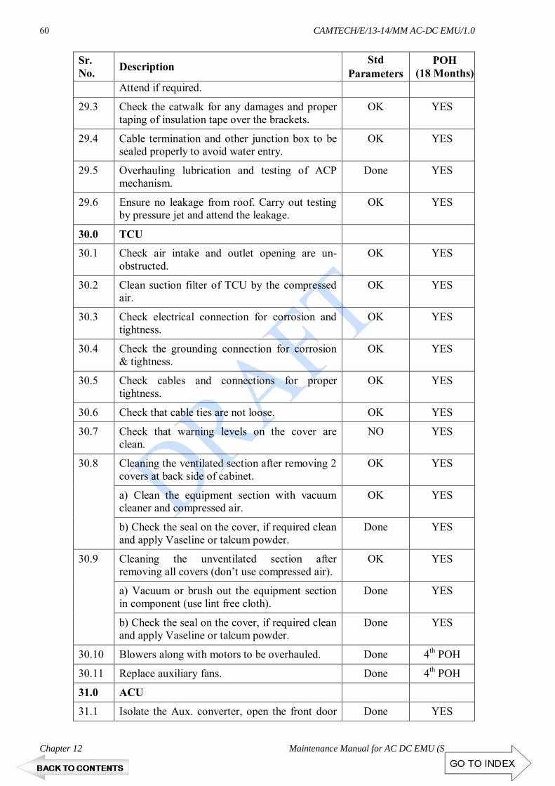
CAMTECH/E/13-14/MM AC-DC EMU/1.0
Chapter 12 Maintenance Manual for AC DC EMU (Siemens)
60
Sr. No. Description Std
Parameters POH
(18 Months) Attend if required.
29.3 Check the catwalk for any damages and proper taping of insulation tape over the brackets.
OK YES
29.4 Cable termination and other junction box to be sealed properly to avoid water entry.
OK YES
29.5 Overhauling lubrication and testing of ACP mechanism.
Done YES
29.6 Ensure no leakage from roof. Carry out testing by pressure jet and attend the leakage.
OK YES
30.0 TCU
30.1 Check air intake and outlet opening are un-obstructed.
OK YES
30.2 Clean suction filter of TCU by the compressed air.
OK YES
30.3 Check electrical connection for corrosion and tightness.
OK YES
30.4 Check the grounding connection for corrosion & tightness.
OK YES
30.5 Check cables and connections for proper tightness.
OK YES
30.6 Check that cable ties are not loose. OK YES
30.7 Check that warning levels on the cover are clean.
NO YES
30.8 Cleaning the ventilated section after removing 2 covers at back side of cabinet.
OK YES
a) Clean the equipment section with vacuum cleaner and compressed air.
OK YES
b) Check the seal on the cover, if required clean and apply Vaseline or talcum powder.
Done YES
30.9 Cleaning the unventilated section after removing all covers (don’t use compressed air).
OK YES
a) Vacuum or brush out the equipment section in component (use lint free cloth).
Done YES
b) Check the seal on the cover, if required clean and apply Vaseline or talcum powder.
Done YES
30.10 Blowers along with motors to be overhauled. Done 4th POH
30.11 Replace auxiliary fans. Done 4th POH
31.0 ACU
31.1 Isolate the Aux. converter, open the front door Done YES

CAMTECH/E/13-14/MM AC-DC EMU/1.0
Maintenance Manual for AC-DC EMU (Siemens) Chapter 12
61
Sr. No. Description Std
Parameters POH
(18 Months) and ground it.
31.2 Inspect the arc quenching chambers and switch elements.
Done YES
31.3 Visually check whether arc quenching chambers exhibit mechanical damage or metal deposits.
Done YES
31.4 Visually inspect whether material deposits have occurred at the power contacts.
OK YES
31.5 In events of faults replace the defective component. If the protection is in order re-attach the arc quenching chamber.
OK YES
31.6 Inspect the components for any damage and check that they are firmly sealed. (discoloration or mechanical damage)
OK YES
31.7 Check the power modules, controls, fans and current & voltage sensors.
Done YES
31.8 Check healthiness ACU internal cabling. Done YES
31.9 Check the tightness of line connections. OK YES
31.10 Inspect the plugs for corrosion and proper contact.
OK YES
31.11 Check the tightness of plug clamping screws. Replace if needed.
OK YES
31.12 Open the pivoting frame and clean the fan with vacuum cleaner.
Done YES
31.13 Mount the fan cover panel (8XM6 torque - 6.5Nm), close the pivoting frame (2XM8 torque -15Nm) tight.
Done YES
31.14 Fan to be removed and fan area to be cleaned. Done YES
31.15 Anti corrosion bags to be replaced. Done YES
31.16 Cleaning of air intake point, air duct and cooling ribs etc.
Done YES
31.17 Power module fans to be replaced. Done 4th POH
31.18 Check the cable connection of fuses & ensure the healthiness of fuses.
Done Every POH
32.0 CCU
32.1 Clean the dust with soft brush and vacuum cleaner.
Done YES
33.0 BECU
33.1 Check for any abnormality. OK YES
33.2 Clean with Vacuum Cleaner. OK YES

CAMTECH/E/13-14/MM AC-DC EMU/1.0
Chapter 12 Maintenance Manual for AC DC EMU (Siemens)
62
Sr. No. Description Std
Parameters POH
(18 Months) 33.3 Check speed sensor intactness provided in C
coach. OK YES
34.0 TRAIN LINE JUNCTION BOX
34.1 Open and blow out the dust with compressed air.
Done YES
34.2 Clean the terminal with nylon brush. OK YES
34.3 Check tightness of all the connections. OK YES
34.4 See that all wires are numbered. OK YES
35.0 AHU
35.1 Remove the filter from the coach, clean it by immersing the filter in a tank filled with soap/detergent water (mild hot). The jet of high pressure air should not be used for cleaning.
Done YES
35.2 Replaced the damaged ventilation filters. Done YES
35.3 Verify the healthiness of stainless steel earthing block welded to coach end wall. They should be clear and free from paint residues.
OK YES
35.4 Check the intactness of electrical connection after O/H of the AHU.
OK YES
35.5 Check the blower for any abnormal sound and attend.
OK YES
35.6 Remove and Overhaul the blowers. Done 4th POH
36.0 BLOWER MOTORS (TCU, ACU, Radiator fan)
36.1 Check the direction and working of all blower motors.
OK YES
36.2 Ensure No blower motor working with abnormal sound.
OK YES
36.3 Measure Phase current of all the Blower Motor by tongue tester.
OK YES
36.4 Grease the bearing of the pump using grease gun and nipple
Done YES
36.5 Remove the auxiliary motors and Overhaul Done 4th POH
36.6 Check the availability of Equi-potential Cables & Bogie to Coach sole bar Earthing Shunts.
OK YES
37.0 SIBAS KLIP STATION & MVB REPEATER
37.1 Check visually for any abnormality. OK YES
37.2 Clean with help of soft brush. Done YES

CAMTECH/E/13-14/MM AC-DC EMU/1.0
Maintenance Manual for AC-DC EMU (Siemens) Chapter 12
63
Sr. No. Description Std
Parameters POH
(18 Months) 37.3 Check the tightness of connection in KLIP
station and contactor panel. OK YES
38.0 AC-DC COS
38.1 Visual inspection of insulators, contacts and foundations.
OK YES
38.2 Cleaning of insulators. OK YES
38.3 Inspection of disconnecting knife and contact spring.
OK YES
38.4 Check revolving mechanism for free movement. OK YES
38.5 Checking of operation of pneumatic cylinder and EMV valve.
OK YES
38.6 Replace damaged and faulty parts. OK YES
38.7 Measure the contact spring contact force. 20-40 N YES
38.8 Contact Opening. 10mm YES
38.9 Overhauling of AC-DC COS. Done 2nd POH
39.0 BOGIE
39.1 Lift the coaches, clean the bogies and check for cracks and attend.
Done YES
39.2 Replace defective/worn out bogie parts sub assemblies.
Done YES
39.3 Complete dismantling and overhauling. Done YES
39.4 Ensure square-ness of bogie frame By trammling gauge.
Done YES
39.5 Check the centre pivot pin for any crack/ breakages and Replace with single piece forged type C.P. pin if required.
OK
YES
39.6 Replace non standard guide bush of centre pivot body bolster if required.
OK YES
39.7 Check for any abnormalities of side bearers, covers, wearing piece, wearing plate & housing and attend for leak proof by providing oil top up arrangement.
OK YES
40.0 BRAKE CYLINDER
40.1 Overhaul. Done YES
40.2 Check fixing bolts of brake cylinders for any damages or slackness.
OK YES
40.3 Check brake rigging parts i.e. pins, nut bolts, cutters, split pins of brake block key shoe head pins for missing, worn out, slackness.
OK YES

CAMTECH/E/13-14/MM AC-DC EMU/1.0
Chapter 12 Maintenance Manual for AC DC EMU (Siemens)
64
Sr. No. Description Std
Parameters POH
(18 Months) 41.0 BRAKE RIGGING
41.1 Replace all brake blocks. Done YES
41.2 Ensure gap adjustment between brake block and wheel.
>12 mm YES
41.3 Ensure tightness of brake shoe key. OK YES
41.4 Check Pins, nuts, bolts, cotters, washers for worn out, breakages and stopper plate. Tighten them and replace if required.
OK YES
41.5 Check Brake hangers, brake beams, and other brake rigging components. Replace if required.
OK YES
41.6xx Replace the brake hanger nylon bush. Done YES
41.7 Lubricate all the moving parts. OK YES
41.8 Check the condition of safety brackets and looseness of fixing bolt.
OK YES
41.9 Check for any damage or abnormality on brake yoke assembly.
OK YES
41.10 100% replacement of all type of bushes. Done YES
41.11 Replacement of pins on condition basis. Done YES
41.12 100% replacement of pins. Done 2nd POH
42.0 DASHPOT
42.1 Check for oil leakage. OK YES
42.2 Check the oil level with dip stick and top up if necessary (97mm). Record quantity of oil fill up in Dash pot.
OK YES
42.3 Check for any breakages of dashpot spring and dashpot top covers.
OK YES
42.4 Cleaning and lubrication of Dash pot springs. OK YES
42.5 100% replacement of rubber packing. Done YES
42.6 Check dashpot guide bush and replace if required.
Done YES
43.0 AIR SUSPENSION
43.1 Check the foundation allen bolts intactness. OK YES
43.2 Check for any cracks, dent marks, leakages, and hitting marks on air balloon.
OK YES
43.3 Check the foundations and fitment of vertical dampers. If damper not working replace it.
OK YES
43.4 Check the leveling valve assembly for any leakage, replace if required.
OK YES

CAMTECH/E/13-14/MM AC-DC EMU/1.0
Maintenance Manual for AC-DC EMU (Siemens) Chapter 12
65
Sr. No. Description Std
Parameters POH
(18 Months) 43.5 Check the adjusting lever rods and adjust the
clearances if found abnormal. OK YES
43.6 Adjust the Installation lever in horizontal position.
OK YES
43.7 Check all the cocks provided for air springs are working if not replace them.
Done YES
43.8 Check for all the air spring cocks are in open position.
OK YES
43.9 Drain all the cocks provided in air spring tank. OK YES
43.10 Check all the pipes, couplings for any leakage and attend it.
Done YES
43.11 Check for any rubbing/ abnormality on the flexible pipes provided in air spring and replace them as required.
OK YES
43.12 100% replacement of flexible hoses. Done 2nd POH
43.13 Check the function of duplex check valve by operating leveling valve of same bolster alternately.
OK YES
43.14 Overhaul all control valves, leveling valve, duplex check valve.
OK YES
43.15 Overhaul air springs, retest & refit. Done YES
43.16 Replace the CDC filter element. Done YES
44.0 SHOCK-ABSORBERS
44.1 Replacement of oil, rubber kit and load testing of vertical and lateral shock absorber.
Done YES
44.2 100% replacement of all the shock absorber. Done 4th POH
45.0 WHEELS AND AXLES
45.1 Re-profiling of Wheels. OK YES
45.2 Overhauling of axle box and attention to roller bearing.
Done YES
45.3 Ultrasonic testing of Axle. Done YES
45.4 Perform magna flux test on each wheel with the help of magna flux test magnet.
Done YES
45.5 Measure the wheel distance with the help of wheel distance gauge.
Done YES
46.0 DRAW & SHACKU COUPLER
46.1 Check draw bar and allen key bolts. OK YES
46.2 Check Articulation bearing. Replace if required. OK YES

CAMTECH/E/13-14/MM AC-DC EMU/1.0
Chapter 12 Maintenance Manual for AC DC EMU (Siemens)
66
Sr. No. Description Std
Parameters POH
(18 Months) 46.3 Replace Fiber bush required if. OK YES
46.4 Greasing of articulation bearing. OK YES
46.5 Overhaul as per OEM manual. Done YES
46.6 Screw coupling : Check and ensure sound fixation and lubricate oil.
Done YES
46.7 Ensure intactness of fasteners. OK YES
47.0 FURNISHING ITEMS
47.1 Replacement of lookout glass at motormen side on condition basis.
Done YES
47.2 Check operation (open/close/locking) of D/cab and passenger area doors and replace door roller if found defective.
OK YES
47.3 Attend doors for stopper, tower bolts, latches, handles.
OK YES
47.4 Replacement of defective D/cab and passenger area windows locks, springs, Rubber Gasket, safety mesh.
Done YES
47.5 Replacement of worn out/ broken chequred sheets.
Done YES
47.6 Provide missing glass and louver shutter including complete window frame.
OK YES
47.7 Provide missing notice plates. OK YES
47.8 Provide ACP handles, ACP ropes, ACP Springs, Rods, cover etc.
OK YES
47.9 Check the condition of trough floor OK YES
47.10 Check for any abnormality in handicap compartment, luggage compartments.
OK YES
47.11 Dismantle, attend and change the cover of seat and back rest.
OK YES
47.12 Ensure functioning of windows & doors. Done YES
47.13 Replace missing Grab Handles and ensure proper welding of grab handles in door-ways.
Done YES
47.14 Ensure functioning of D-Cab window glass. Done YES
47.15 Passenger door and D-cab door and rubber buffing profile to be replaced on condition basis.
OK YES
47.16 Check luggage compartment partition for missing of SS sheet securing patti, if found missing to be attend.
OK YES

CAMTECH/E/13-14/MM AC-DC EMU/1.0
Maintenance Manual for AC-DC EMU (Siemens) Chapter 12
67
Sr. No. Description Std
Parameters POH
(18 Months) 47.17 Replacement of defective lookout glass curtains. Done YES
47.18 Motor coach HT compartment defective locks to be replaced.
OK YES
47.19 Proper securing of hatch door to be ensured. OK YES
47.20 Check for Roof corrosion, Paint corroded. OK YES
47.21 Replace Ist class seat cushion/ driver seats. OK 4th POH
47.22 Special attention in DTC, HT compartment , End wall & AHU to prevent the ingress of water in rainy season.
Done YES
47.23 Ensure healthiness of Locks / tower bolt provided on coach End wall panel doors.
Done YES
47.24 Ensure proper locking of each & every door viz E-Cabinet of D/cab & MC, Various cabinet door in HTC.
OK YES
47.25 Roof painting OK YES
47.26 Complete Repainting OK 4th POH
48.0 FINAL TESTING
A Pneumatic Testing
48.1 Switch on DCS key and observe on MMI.
48.2 Check application of holding brakes in all coaches.
a) DCS key "ON" position 0.8 Kg/cm2 YES
b) DCS key "OFF" position 1.2 Kg/cm2 YES
48.3 Check BP pressure charging time from both cabs 0 to 4.9 kg/cm2.
90-100 Sec YES
48.4 Check MR and BP drop test in 10 minutes. not more than
1.0kg/cm2
YES
48.5 Ensure MR and BP pipe pressure continuity. OK YES
48.6 EP Brake Application
a) Application Timing 4-6sec YES
b) Release Timing 4-6 sec YES
48.7 Auto Brake Application
a) Application Timing 6-10 Sec YES
b) Release Timing <20 Sec YES
48.8 Emergency brake By Power Brake Controller

CAMTECH/E/13-14/MM AC-DC EMU/1.0
Chapter 12 Maintenance Manual for AC DC EMU (Siemens)
68
Sr. No. Description Std
Parameters POH
(18 Months) a) Application Timing 4-6sec YES
b) Release Timing 4-6 sec YES
48.9 Emergency brake By Brake Controller
a) Application Timing 4-6 Sec YES
b) Release Timing <20 Sec YES
48.10 Check working of Brake Controller at all positions and ensure No leakage in release and auto lap position from Brake Controller.
Ok YES
48.11 Check each coach Brake Cylinders for Leakage. OK YES
48.12 Ensure proper working of Duplex Pressure Gauge, BC Gauge, Parking Brake and Guard's Gauge.
OK YES
48.13 Ensure Parking Brake application & release. OK YES
48.14 Ensure Parking Brake gauge shows 0 pressure in applied condition and 5 kg/cm2 in released condition.
OK YES
48.15 Ensure the working of Parking Brake Push button.
OK YES
48.16 Ensure No EP unit should have air leakage in both release and applied condition.
OK YES
48.17 Ensure no EP Unit should be Hunting. OK YES
48.18 Ensure the provision of safety valve in all brake units.
OK YES
48.19 Ensure the healthiness of Brake Units Safety Valves by applying Auto Brake.
OK YES
48.20 Check and ensure Brake Cylinder Pressure of all coaches should not be more than specified limit.
1.2 kg/cm2-DTC/TC
1.6kg/cm2-MC
YES
48.21 Ensure functioning of Emergency Valve by keeping PBC on EB position.
OK YES
48.22 Ensure effective functioning of Guards Emergency Brake.
OK YES
48.23 Check the function of Auto Drain Valve. YES
48.24 Check and ensure no air leakage in pipe line, couplings & hoses pipes.
OK YES
48.25 Check rubbing of hose pipes and shifting of end nipples.
OK YES
48.26 Check & ensure that clamping arrangements of pipes is as per RDSO Drg.
OK YES

CAMTECH/E/13-14/MM AC-DC EMU/1.0
Maintenance Manual for AC-DC EMU (Siemens) Chapter 12
69
Sr. No. Description Std
Parameters POH
(18 Months) 48.27 Check and ensure Smooth Operation of each
coach MR& BP Cocks. OK YES
48.28 Ensure smooth operation of Horn Foot Valve. OK YES
48.29 Check the working of Safety valve by applying of auto brakes.
should be blow
YES
48.30 Ensure the working of Air Dryers and note their Tower Change Over Cycle Time.
120sec YES
48.31 Check working of AWS Feed Cut Off Valve and Exhaust Valve.
OK YES
48.32 Check and ensure smooth operation of AWS Cocks.
OK YES
48.33 Check working of both Cab Wipers and ensure wiping action of wiper blade.
OK YES
48.34 Check Cut in & Cut Out Setting of Auxiliary Compressor.
6.3 kg/cm2-5.3kg/cm2
YES
48.35 Check and ensure that there is no Air Leakage from the Panto-magnet valve.
OK YES
48.36 Check the healthiness of all Coaches Air Spring Suspension System & Leveling Valve.
OK YES
48.37 Check Cut In & Cut Out setting of Main Compressor.
Cut in - 7.0 kg/cm2
Cut out -8.0 kg/cm2
YES
48.38 Ensure availability of Fire Extinguisher in all Motor coaches.
OK YES
48.39 Ensure availability of Short Circuit Clips, Wooden Wedge, Fire Extinguisher, ACP Bamboo etc. in DTC.
OK YES
49.0 ELECTRICAL TESTING
49.1 Keep MMI in maintenance mode. OK YES
49.2 Check on MMI that all coaches are set. OK YES
49.3 Check the healthiness of each and every function physically which are displayed on various screens (Top level, Unit Level, Drive/Brake, Energy, Fault logged, V > 0 & V = 0) of MMI.
OK YES
49.4 Check for any Error Message on the screen. OK YES
49.5 Check CB set / trip on MMI. OK YES
49.6 Check Panto Raising/Lowering timing on MMI. 6-10 Sec YES

CAMTECH/E/13-14/MM AC-DC EMU/1.0
Chapter 12 Maintenance Manual for AC DC EMU (Siemens)
70
Sr. No. Description Std
Parameters POH
(18 Months) 49.7 Check working of Fan, Light and Ventilation
(both 50% and 100%) OK YES
49.8 Check changeover on MMI for 415V AC, 110V AC, 110V DC by operating Basic Unit Isolating Switch.
OK YES
49.9 Check Healthiness of various Lamp Indication by Pushing Test Push Button.
OK YES
49.10 Check working of Head Light, Auxiliary Head Light, Flasher, Tail Light and Blinker Lights on various positions
OK YES
49.11 Check working of Signal bell, Emergency bells and their indication.
OK YES
49.12 Check for Healthiness of Head-codes. OK YES
49.13 Check working of PA/PIS & TMS system. i) Cab to Cab (PA & TMS) ii) Cab to Passenger (PA)
OK YES
49.14 Check operation of " BA Reset " switch OK YES
49.15 Check working of " Emy OFF Loop Push Button "
OK YES
49.16 Check the function of all Isolating Switches provided on E-Cabinet.
OK YES
49.17 Ensure No isolation of Rotary Switches & MCBs in trip position
OK YES
49.18 Check functionality of Entering Neutral Section Push Button by observing feed back on SKS 12 & 13
OK YES
49.19 Ensure no any ground fault in 110V AC & 110 DC circuits.
OK YES
49.20 Observe all Sensors Feed Back Signals in "Observer" by laptop i.e. COS Timing, BECU speed sensors, BC pressure, EP Unit pressure transducer, etc
OK YES
49.21 Check working of Passenger Alarm by pulling of ACP from each coach.
OK YES
49.22 Check and ensure Flasher Indication Provided outside on all ladies compartment while ACP pulled.
OK YES
49.23 Check working of Dead man valve in normal and RDM mode .
OK YES
49.24 Run down the Rake in Normal and RDM mode from DTC as well as from each Motor Coach.
OK YES

CAMTECH/E/13-14/MM AC-DC EMU/1.0
Maintenance Manual for AC-DC EMU (Siemens) Chapter 12
71
Sr. No. Description Std
Parameters POH
(18 Months) 49.25 Check working of AWS Speedometer and
Speed recorder. OK YES
49.26 List of Modification being done. OK YES
49.27 Check MCBs and Replace defective MCBs. OK YES
49.28 Check and ensure the MVB Healthiness as per SIEMENS protocol.
OK YES
49.29 Testing of rake to be carried out as per the Testing Protocol at Annexure-I.
OK YES
49.30 Ensure all the Modifications as per check list (Annexure II).
OK YES
49.31 Down load the events of all motor coach TCU, BCU, ACU and both CCU and to analyze.
OK YES
50.0 MEASUREMENT OF CLEARANCES OF BOGIE PARTS AND WHEEL
50.1 Between bogie bolster and top of bogie frame
TC - 97 mm MC HT -97 mm NHT -103 mm
YES
50.2 Between bogie bolster and bottom of bogie frame
35 mm - 45 mm
YES
50.3 Between axle box crown and bottom of bogie frame
TC 42 - 48mm MC HT - 25-
31mm NHT - 35-
41mm
YES
50.4 Buffer height 1030 -1035 mm/ YES
50.5 Size of wheel TC 857-952mm MC 877-952mm
YES
50.6 Distance of wheels on axle 1600 mm -2/+1 YES
50.7 Height of cattle guard from rail level 150 to 200 mm YES
50.8 Clearance between bolster and transom liner. Not more than 3mm YES
50.9 Measure bogie frame height 688 ± 5 mm YES
50.10 Measure sole bar bottom height 915mm YES

CAMTECH/E/13-14/MM AC-DC EMU/1.0
Chapter 12 Maintenance Manual for AC DC EMU (Siemens)
72
12.10 STORAGE REGULATIONS FOR RUBBER-METAL COMPONENTS DIN 7716 must be observed when rubber-metal components are stored. DIN 7716 contains the following key statements which are applicable to rubber-metal components:
Storage area # The storage area should be cool, dry and adequately ventilated. # The storage area must be protected from the weather.
Temperature # Rubber-metal components should not be stored at temperatures below –10 °C or above +25 °C. # The storage area temperature may exceed these upper and lower limits for brief periods only.
Humidity # The components should not be stored in damp rooms. # Care should be taken to ensure that condensation does not form. The most favorable conditions are at a relative humidity of less than 65%.
Lighting # The components should be protected from light, especially from direct sunlight or strong artificial light with a high proportion of UV.
Oxygen and ozone # The components should be protected against frequent air changes, especially drafts, by wrapping them up, storing them in airtight containers or other means. # As ozone can be particularly destructive, the storage areas must not contain any equipment or devices which produce ozone, such as electric motors or other devices which could produce sparks or other electrical discharges.
Chemicals # Solvents, fuels, lubricants, chemicals, acids, disinfectants and similar substances must not be stored in the same room. # The materials of the containers used for packaging and covering consumables must not contain constituents which could damage the components, e.g. copper or copper-based alloys, petroleum products, oil or similar.
Film containing plasticizers must not be used for packaging! # Any protective layers used on the equipment must not have any detrimental effects on the elastomer or the rubber-metal bond.

CAMTECH/E/13-14/MM AC-DC EMU/1.0
Maintenance Manual for AC-DC EMU (Siemens) ANNEXURE - I
1
ANNEXURE-1 REFERENCE DRAWINGS
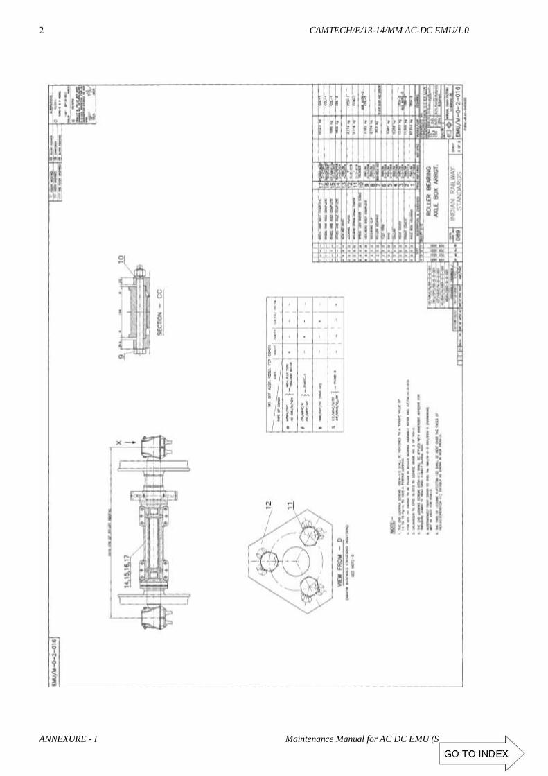
CAMTECH/E/13-14/MM AC-DC EMU/1.0
ANNEXURE - I Maintenance Manual for AC DC EMU (Siemens)
2

CAMTECH/E/13-14/MM AC-DC EMU/1.0
Maintenance Manual for AC-DC EMU (Siemens) ANNEXURE - I
3

CAMTECH/E/13-14/MM AC-DC EMU/1.0
ANNEXURE - I Maintenance Manual for AC DC EMU (Siemens)
4

CAMTECH/E/13-14/MM AC-DC EMU/1.0
Maintenance Manual for AC-DC EMU (Siemens) ANNEXURE - I
5

CAMTECH/E/13-14/MM AC-DC EMU/1.0
ANNEXURE - I Maintenance Manual for AC DC EMU (Siemens)
6

CAMTECH/E/13-14/MM AC-DC EMU/1.0
Maintenance Manual for AC-DC EMU (Siemens) ANNEXURE - I
7

CAMTECH/E/13-14/MM AC-DC EMU/1.0
ANNEXURE - I Maintenance Manual for AC DC EMU (Siemens)
8

CAMTECH/E/13-14/MM AC-DC EMU/1.0
Maintenance Manual for AC-DC EMU (Siemens) ANNEXURE - I
9

CAMTECH/E/13-14/MM AC-DC EMU/1.0
ANNEXURE - I Maintenance Manual for AC DC EMU (Siemens)
10

CAMTECH/E/13-14/MM AC-DC EMU/1.0
Maintenance Manual for AC-DC EMU (Siemens) ANNEXURE - I
11

CAMTECH/E/13-14/MM AC-DC EMU/1.0
ANNEXURE - I Maintenance Manual for AC DC EMU (Siemens)
12

CAMTECH/E/13-14/MM AC-DC EMU/1.0
Maintenance Manual for AC-DC EMU (Siemens) ANNEXURE - I
13

CAMTECH/E/13-14/MM AC-DC EMU/1.0
ANNEXURE - I Maintenance Manual for AC DC EMU (Siemens)
14

CAMTECH/E/13-14/MM AC-DC EMU/1.0
Maintenance Manual for AC-DC EMU (Siemens) ANNEXURE - I
15

CAMTECH/E/13-14/MM AC-DC EMU/1.0
ANNEXURE - I Maintenance Manual for AC DC EMU (Siemens)
16

CAMTECH/E/13-14/MM AC-DC EMU/1.0
Maintenance Manual for AC-DC EMU (Siemens) ANNEXURE - I
17

CAMTECH/E/13-14/MM AC-DC EMU/1.0
ANNEXURE - I Maintenance Manual for AC DC EMU (Siemens)
18

CAMTECH/E/13-14/MM AC-DC EMU/1.0
Maintenance Manual for AC-DC EMU (Siemens) ANNEXURE - I
19

CAMTECH/E/13-14/MM AC-DC EMU/1.0
ANNEXURE - I Maintenance Manual for AC DC EMU (Siemens)
20

CAMTECH/E/13-14/MM AC-DC EMU/1.0
Maintenance Manual for AC-DC EMU (Siemens) ANNEXURE - I
21

CAMTECH/E/13-14/MM AC-DC EMU/1.0
ANNEXURE - I Maintenance Manual for AC DC EMU (Siemens)
22

CAMTECH/E/13-14/MM AC-DC EMU/1.0
Maintenance Manual for AC-DC EMU (Siemens) ANNEXURE - I
23

CAMTECH/E/13-14/MM AC-DC EMU/1.0
ANNEXURE - I Maintenance Manual for AC DC EMU (Siemens)
24

CAMTECH/E/13-14/MM AC-DC EMU/1.0
Maintenance Manual for AC-DC EMU (Siemens) ANNEXURE - I
25

CAMTECH/E/13-14/MM AC-DC EMU/1.0
ANNEXURE - I Maintenance Manual for AC DC EMU (Siemens)
26

CAMTECH/E/13-14/MM AC-DC EMU/1.0
Maintenance Manual for AC-DC EMU (Siemens) ANNEXURE - I
27

CAMTECH/E/13-14/MM AC-DC EMU/1.0
ANNEXURE - I Maintenance Manual for AC DC EMU (Siemens)
28

CAMTECH/E/13-14/MM AC-DC EMU/1.0
Maintenance Manual for AC-DC EMU (Siemens) ANNEXURE - I
29

CAMTECH/E/13-14/MM AC-DC EMU/1.0
ANNEXURE - I Maintenance Manual for AC DC EMU (Siemens)
30

CAMTECH/E/13-14/MM AC-DC EMU/1.0
Maintenance Manual for AC-DC EMU (Siemens) ANNEXURE - I
31

CAMTECH/E/13-14/MM AC-DC EMU/1.0
ANNEXURE - I Maintenance Manual for AC DC EMU (Siemens)
32

CAMTECH/E/13-14/MM AC-DC EMU/1.0
Maintenance Manual for AC-DC EMU (Siemens) ANNEXURE - I
33

CAMTECH/E/13-14/MM AC-DC EMU/1.0
ANNEXURE - I Maintenance Manual for AC DC EMU (Siemens)
34

CAMTECH/E/13-14/MM AC-DC EMU/1.0
Maintenance Manual for AC-DC EMU (Siemens) ANNEXURE - I
35

CAMTECH/E/13-14/MM AC-DC EMU/1.0
ANNEXURE - I Maintenance Manual for AC DC EMU (Siemens)
36

CAMTECH/E/13-14/MM AC-DC EMU/1.0
Maintenance Manual for AC-DC EMU (Siemens) ANNEXURE - I
37

CAMTECH/E/13-14/MM AC-DC EMU/1.0
ANNEXURE - I Maintenance Manual for AC DC EMU (Siemens)
38

CAMTECH/E/13-14/MM AC-DC EMU/1.0
Maintenance Manual for AC-DC EMU (Siemens) ANNEXURE - I
39

CAMTECH/E/13-14/MM AC-DC EMU/1.0
ANNEXURE - I Maintenance Manual for AC DC EMU (Siemens)
40

CAMTECH/E/13-14/MM AC-DC EMU/1.0
Maintenance Manual for AC-DC EMU (Siemens) ANNEXURE - I
41

CAMTECH/E/13-14/MM AC-DC EMU/1.0
ANNEXURE - I Maintenance Manual for AC DC EMU (Siemens)
42

CAMTECH/E/13-14/MM AC-DC EMU/1.0
Maintenance Manual for AC-DC EMU (Siemens) ANNEXURE - I
43

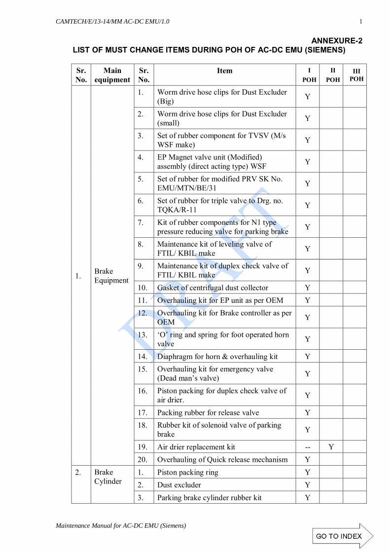
CAMTECH/E/13-14/MM AC-DC EMU/1.0
Maintenance Manual for AC-DC EMU (Siemens) ANNEXURE - 2
1
ANNEXURE-2 LIST OF MUST CHANGE ITEMS DURING POH OF AC-DC EMU (SIEMENS)
Sr.No.
Main equipment
Sr.No.
Item I POH
II POH
III POH
1. Brake Equipment
1. Worm drive hose clips for Dust Excluder (Big) Y
2. Worm drive hose clips for Dust Excluder (small) Y
3. Set of rubber component for TVSV (M/s WSF make) Y
4. EP Magnet valve unit (Modified) assembly (direct acting type) WSF Y
5. Set of rubber for modified PRV SK No. EMU/MTN/BE/31 Y
6. Set of rubber for triple valve to Drg. no. TQKA/R-11 Y
7. Kit of rubber components for N1 type pressure reducing valve for parking brake Y
8. Maintenance kit of leveling valve of FTIL/ KBIL make Y
9. Maintenance kit of duplex check valve of FTIL/ KBIL make Y
10. Gasket of centrifugal dust collector Y 11. Overhauling kit for EP unit as per OEM Y 12. Overhauling kit for Brake controller as per
OEM Y
13. ‘O’ ring and spring for foot operated horn valve Y
14. Diaphragm for horn & overhauling kit Y 15. Overhauling kit for emergency valve
(Dead man’s valve) Y
16. Piston packing for duplex check valve of air drier. Y
17. Packing rubber for release valve Y 18. Rubber kit of solenoid valve of parking
brake Y
19. Air drier replacement kit -- Y 20. Overhauling of Quick release mechanism Y
2. Brake Cylinder
1. Piston packing ring Y 2. Dust excluder Y 3. Parking brake cylinder rubber kit Y

CAMTECH/E/13-14/MM AC-DC EMU/1.0
ANNEXURE - 2 Maintenance Manual for AC DC EMU (Siemens)
2
LIST OF MUST CHANGE ITEMS DURING POH OF AIR SUSPENSION
Sr.No.
Main equipment
Sr.No.
Item I POH
II POH
III POH
1. TCU
1. Replacement of cooling fans bearings/ overhauling Y
2. Replacement of TCU Buffer Batteries Y
3. Replacement of TCU cabinet cover gasket & air filters Y
2. MMI
1. Replacement of tail tell lamp Y
2. Replacement of CCFL & cooling fan (2nd POH) Y
3. Replacement of all switches (soft keys) of MMI Y
3. ACU
1. Replace the drying agents provided inside the ACU compartment Y
2 Replace the bearings of cooling fans Y
3 Replace the power module fans & foundation Y
4 Replace the internal fans of the modules 2. Y
5 ACU cabinet cover gasket Y
6 Replacement of Air filters Y
7 Replacement of all fuses Y
3 Driver’s
Cab equipment
1. Actuator & Switching element: Head light ON-OFF, Aux.-Main & Dim-bright
Y
2 Push button & switching element: Flasher, Blinker, Tail light, coach light 100%
Y
3 Fuses of blinker, flasher, tail light, head light, DC-DC converter Y
4 MC on/off, panto up/ down, entering neutral section cruise control switch in driving cab Y
5 In motor coach MC on/ off, Panto On/ Off switch
6 Switching element of EMG off, SBI, SBII, parking brake, audio-visual Y
4 Master Controller
1 Springs for master controller Y 2 Micro switches Y 3 Elen screw for master controller Y 4 Replacement of key lock Y
5. VCB
1 Overhauling AOH kit Y 2 Overhauling IOH kit Y 3 Overhauling POH kit Y 4. Rubber Hose pipe Y

CAMTECH/E/13-14/MM AC-DC EMU/1.0
Maintenance Manual for AC-DC EMU (Siemens) ANNEXURE - 2
3
Sr.No.
Main equipment
Sr.No.
Item I POH
II POH
III POH
6. AHU 1 Replacement of bearing Y
2 Replacement of air filters Y
7. Battery 1. Replace with new one Y
2. Replacement of battery fuse Y
8. Others
1 Replacement of all drivers desk, shunting desk, BECU, E-cabinet, doors, rubber gasket Y
2 Replacement of all under-gear, bogie to body shunts/cables Y
3 Replacement of CCU battery Y
4 Replacement of all connector rubber gasket with cable tie. Y
5 Nut bolt of Hatch door Y
6 Nut bolt of DBR protection cover Y
7 Nut bolt of AHU cover of roof Y
8 Replacement of all hardware of all roof equipment Y
9 Replacement of all roof equipment cables & shunts Y
10 Rubber pipe of COS Y
11 COS flexible shunts Y

CAMTECH/E/13-14/MM AC-DC EMU/1.0
ANNEXURE - 2 Maintenance Manual for AC DC EMU (Siemens)
4
MUST CHANGE ITEM DURING POH
Sr.No.
Main equipment
Sr.No.
Item Every POH
2nd POH
3rd POH
1. MCB with Feedback
1 Cab occupation Y
2 Master controller Y
3 CCU supply Y
4 Panto and MC supply Y
5 TCC and TCU supply Y
6 SKS 12 Y
7 SKS 13 Y
8 Emg off, MMI Y
2. Contactor with add- on block
1. D-cab 22 K01, 22k02, 22k06, 22k07, 22k10, 43k06,43k07,44k01 Y
2 In motor coach 43 k07, 43k08, 43k01, 43k02 Y
3. Pipes
1 MR hose pipe Y
2 BP hose pipe Y
3 Bogie hose pipe Y
4 Parking brake pipe Y
5 Levelling valve pipe Y

CAMTECH/E/13-14/MM AC-DC EMU/1.0
Maintenance Manual for AC-DC EMU (Siemens) ANNEXURE - 2
5
LIST OF MUST CHANGE ITEMS DURING POH OF AIR SUSPENSION BOGIE
Sr.No.
Main equipment
Sr.No.
Description Every POH
Every alternate
POH
Every third POH
1 Traction Motor
1 Change the gear case oil Y
2 Change the rubber sand-witch O-Ring & gear case felt
Condition basis
Condition basis
Condition basis
3 Replacement of leather bellows Y
4 Replacement of Air filters Y
5 Rubber sand-witch unit Y
6 TM Hardware Y
2. Main Compressor
1 Replace the resilient mounts after the service life of 3 years Y
2 Replacement of suction filters & oil breather filter Y
3 Valve plates and packing ring for Aux. compressor Y
4 Overhauling kit alternate POH for compressor as per OEM Y
5 Overhauling kit every third POH for compressor as per OEM Y
6 Compressor Air drier pipe Y
7 Compressor oil Y
3 Transformers
1 Replacement the silica gel of the breather with new and dry one, silica gel container rubber ring
Y
2 Radiator (Heat Exchanger) blower motor foundation dampers Y
3 Radiator (Heat Exchanger) to be replaced after 10 years.
4. Earth return
brushes (ERB)
1 Rubber packing between ERB housing and MSU to be replaced. Y
2 Replacement of ERB
On
cond
ition
bas
is
Y

CAMTECH/E/13-14/MM AC-DC EMU/1.0
ANNEXURE - 2 Maintenance Manual for AC DC EMU (Siemens)
6
LIST OF MUST CHANGE ITEMS DURING POH OF AIR SUSPENSION BOGIE
Sr.No.
Main equipment
Sr.No.
Description Every POH
Every alternate
POH
Every third POH
1. Panto (Schunk make)
1 Rubber kit of pressure regulator throttle valve and inlet filter Y
2 All flexible shunts Y
3 Steel cable (wire rope) Y
4 Rubber bellow Y
2. Panto (Stone India limited Make)
1 Replacement of all split pins Y
2 Yoke assembly bearing 6302 Y
3 All others bearing (lower frame, middle, upper articulation, push rod bearings) Y
4 Rubber kit of throttle valve Y
5 All flexible shunts Y

CAMTECH/E/13-14/MM AC-DC EMU/1.0
Maintenance Manual for AC-DC EMU (Siemens) ANNEXURE - 2
7
REFERENCES

CAMTECH/E/13-14/MM AC-DC EMU/1.0
ANNEXURE - 2 Maintenance Manual for AC DC EMU (Siemens)
8
If you have any suggestions and any specific Comments please write to us. Contact person : Director (Elect.) Postal Address : Indian Railways
Centre for Advanced Maintenance technology, Maharajpur, Gwalior. Pin code – 474 005
Phone : 0751 – 2470740
0751 – 2470803 Fax : 0751 – 2470841 Email : [email protected]
OUR OBJECTIVE
To upgrade maintenance technologies and methodologies and achieve improvement in
productivity, performance of all Railway assets and manpower which inter-alia would cover reliability, availability, utilisation and
efficiency.