Embed Size (px)
Citation preview
FOLDED MONOPOLE ANTENNA FORHANDHELD DEVICES
Qinjiang Rao and Geyi WenResearch In Motion, 185 Columbia Street West, Waterloo,N2L 5Z5, ON, Canada; Corresponding author:[email protected]
Received 18 May 2009
ABSTRACT: This article presents a new multiband antenna forhandheld devices. The antenna consists of three branches of foldedmonopoles, and it is designed to operate at most application bands used
currently, such as GSM 850/900/1800/1900, UMTS2100, and WLAN5 GHz. The simulated and measured results validate the proposed
design. The proposed antenna has better performances than otherembedded antenna designs of the same maximum dimension. VC 2009
Wiley Periodicals, Inc. Microwave Opt Technol Lett 52: 421–425, 2010;
Published online in Wiley InterScience (www.interscience.wiley.com).
DOI 10.1002/mop.24930
Key words: multiband antennas; handheld devices; monopole
antennas
1. INTRODUCTION
Modern wireless handheld devices provide multiple services,
such as GSM, WLAN, UMTS, and are required to be small at
the same time. An antenna has an upper limit of the product of
gain and bandwidth once its maximum size is fixed [1]. As a
result, small antenna design for multiband applications has
become a major challenge.
Handheld antenna design is a very difficult process because
of its complicated environment. The usual procedure is to design
an antenna in a simplified environment in its initial stage in
which only major components such as PCB, LCD, and battery
are included, and then further optimization with the environ-
ments are needed for the expected design objectives. There are
many types of handheld antennas, such as PIFAs [2, 3] and
monopoles [4–8].
It is well known that a monopole is one of the most popular
antennas in handheld devices and its length is normally required
to be a quarter of the wavelength of its fundamental mode.
Clearly, a straight monopole cannot be used as an internal
antenna in small handheld devices, so the monopole must be
bent to reduce its size so that it can be accommodated in small
handheld devices [4–8]. It has been proven that the fractional
bandwidth of an antenna is approximately the inverse of its Q
[9]. Thus, one can enhance the bandwidth of an antenna by
reducing its Q [9]. Theory and experiments have validated that
bending a metal antenna and letting it occupy the space as effi-
ciently as possible can reduce its Q. One strategy of increasing
the bandwidth is to have several monopoles of different electri-
cal lengths closely spaced, each of which has a fundamental res-
onant frequency. These closely spaced fundamental resonant fre-
quencies can merge into a wide bandwidth. On the basis of this
idea, we propose a small multiband antenna, which covers
almost all application bands for a handheld device, such as
GSM/850/900/1800/1900, UMTS 2100, and WLAN 5 GHz
bands (4.85–5.9 GHz). The proposed antenna has significant
improvements in performances compared with other conven-
tional folded monopole antennas [5] most of which only cover
dual-bands with a narrow bandwidth.
The article is organized as follows: section 2 illustrates the
structure of the new multiband antenna; section 3 shows the
measured return loss and simulated current distributions; section
4 discusses the thin-wire model for the multiband antenna and
compares the multiband antenna to its thin-wire model; section
5 presents the measured antenna efficiency and gain of the origi-
nal antenna. Finally, section 6 provides a brief conclusion.
2. ANTENNA STRUCTURE
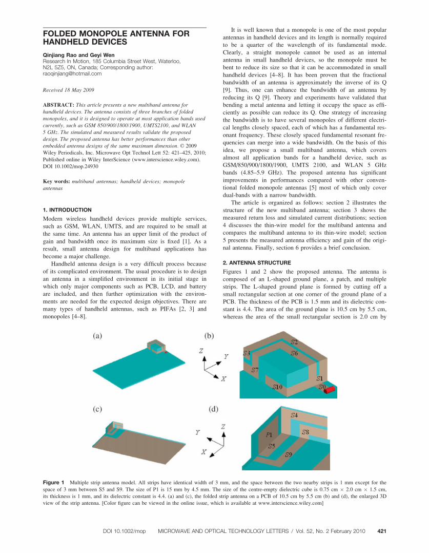
Figures 1 and 2 show the proposed antenna. The antenna is
composed of an L-shaped ground plane, a patch, and multiple
strips. The L-shaped ground plane is formed by cutting off a
small rectangular section at one corner of the ground plane of a
PCB. The thickness of the PCB is 1.5 mm and its dielectric con-
stant is 4.4. The area of the ground plane is 10.5 cm by 5.5 cm,
whereas the area of the small rectangular section is 2.0 cm by
Figure 1 Multiple strip antenna model. All strips have identical width of 3 mm, and the space between the two nearby strips is 1 mm except for the
space of 3 mm between S5 and S9. The size of P1 is 15 mm by 4.5 mm. The size of the centre-empty dielectric cube is 0.75 cm � 2.0 cm � 1.5 cm,
its thickness is 1 mm, and its dielectric constant is 4.4. (a) and (c), the folded strip antenna on a PCB of 10.5 cm by 5.5 cm (b) and (d), the enlarged 3D
view of the strip antenna. [Color figure can be viewed in the online issue, which is available at www.interscience.wiley.com]
DOI 10.1002/mop MICROWAVE AND OPTICAL TECHNOLOGY LETTERS / Vol. 52, No. 2 February 2010 421
1.5 cm. The multiple strips are folded and built on a dielectric
supporting cubic cavity with the dimensions of 0.75 cm � 2.0
cm � 1.5 cm. The dielectric constant of the cavity is 4.4 and its
thickness is 1 mm. Strip S0 is a straight strip and its two ends
are connected to the feeding point and an F-shaped strip S1,
respectively. Strip S2, S4, S6, S7, S8, and S9 are all L-shaped
strips of various sizes; strip S3, S5, and S10 are straight strips.
Patch P1 is connected to strip S5 mostly for impedance match-
ing. These strips constitute three monopoles of different lengths:
The first monopole 1 (S1 þ S2 þ S3 þ S4 þ S5 þ P1), the sec-
ond monopole 2 (S1 þ S6 þ S7 þ S8 þ S9), and the third
monopole 3 (S1 þ S10). The three monopoles are fed through
the strip S0.
3. EXPERIMENTAL AND SIMULATION RESULTS
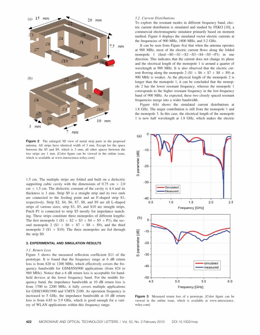
3.1. Return LossFigure 3 shows the measured reflection coefficient S11 of the
prototype. It is found that the frequency range at 6 dB return
loss is from 820 to 1200 MHz, which effectively covers the fre-
quency bandwidth for GSM/850/900 applications (from 824 to
960 MHz). Notice that a 6 dB return loss is acceptable for hand-
held devices at the lower frequency band. For the middle fre-
quency band, the impedance bandwidth at 10 dB return loss is
from 1700 to 2200 MHz, it fully covers multiple applications
for GSM/1800/1900 and UMTS 2100. As operation frequency is
increased to 5 GHz, the impedance bandwidth at 10 dB return
loss is from 4.85 to 5.9 GHz, which is good enough for a vari-
ety of WLAN applications within this frequency range.
3.2. Current DistributionsTo explore the resonant modes in different frequency band, elec-
tric current distribution is simulated and studied by FEKO [10], a
commercial electromagnetic simulator primarily based on moment
method. Figure 4 displays the simulated vector electric currents at
the frequencies of 900 MHz, 1800 MHz, and 5.2 GHz.
It can be seen from Figure 4(a) that when the antenna operates
at 900 MHz, most of the electric current flows along the folded
monopole 1 (feed!S0!S1!S2!S3!S4!S5!P1) in one
direction. This indicates that the current does not change its phase
and the electrical length of the monopole 1 is around a quarter of
wavelength at 900 MHz. It is also observed that the electric cur-
rent flowing along the monopole 2 (S1 þ S6 þ S7 þ S8 þ S9) at
900 MHz is weaker. As the physical length of the monopole 2 is
longer than the monopole 1, it can be concluded that the monop-
ole 2 has the lower resonant frequency, whereas the monopole 1
corresponds to the higher resonant frequency in the low-frequency
band of 900 MHz. As expected, these two closely spaced resonant
frequencies merge into a wider bandwidth.
Figure 4(b) shows the simulated current distributions at
1.8 GHz. The major contribution is still from the monopole 1 and
the monopole 3. In this case, the electrical length of the monopole
1 is now half wavelength at 1.8 GHz, which makes the electric
Figure 2 The enlarged 3D view of metal strip parts in the proposed
antenna. All strips have identical width of 3 mm. Except for the space
between the S5 and S9, which is 3 mm, all other spaces between the
two strips are 1 mm. [Color figure can be viewed in the online issue,
which is available at www.interscience.wiley.com]
Figure 3 Measured return loss of a prototype. [Color figure can be
viewed in the online issue, which is available at www.interscience.
wiley.com]
422 MICROWAVE AND OPTICAL TECHNOLOGY LETTERS / Vol. 52, No. 2 February 2010 DOI 10.1002/mop
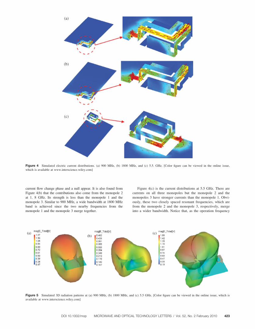
current flow change phase and a null appear. It is also found from
Figure 4(b) that the contributions also come from the monopole 2
at 1. 8 GHz. Its strength is less than the monopole 1 and the
monopole 3. Similar to 900 MHz, a wide bandwidth at 1800 MHz
band is achieved since the two nearby frequencies from the
monopole 1 and the monopole 3 merge together.
Figure 4(c) is the current distributions at 5.5 GHz. There are
currents on all three monopoles but the monopole 2 and the
monopoles 3 have stronger currents than the monopole 1. Obvi-
ously, these two closely spaced resonant frequencies, which are
from the monopole 2 and the monopole 3, respectively, merge
into a wider bandwidth. Notice that, as the operation frequency
Figure 4 Simulated electric current distributions. (a) 900 MHz, (b) 1800 MHz, and (c) 5.5. GHz. [Color figure can be viewed in the online issue,
which is available at www.interscience.wiley.com]
Figure 5 Simulated 3D radiation patterns at (a) 900 MHz, (b) 1800 MHz, and (c) 5.5 GHz. [Color figure can be viewed in the online issue, which is
available at www.interscience.wiley.com]
DOI 10.1002/mop MICROWAVE AND OPTICAL TECHNOLOGY LETTERS / Vol. 52, No. 2 February 2010 423
is increased, multiple nulls appear on the monopoles due to the
increased electrical length.
The currents on the monopole strips and the ground plane
are mainly concentrated along its edge areas. As analyzed in
[10], these edges form what is called the backbone of the metal
antenna or the equivalent wire model.
3.3. Radiation PatternsFigure 5 shows measured 3D radiation patterns of the original
antenna. Notice that radiation patterns are omni-directional
and dipole-like at 900 MHz, but the patterns are directive at
1800 MHz and 5.5 GHz. This is due to the natural features of
unbalanced and balanced antenna in mobile handheld devices.
For mobile handheld devices, the ground plane has significant
impact on the radiation patterns as it is usually a part of the
antenna. When the antenna operates at a lower frequency, such
as 900 MHz, the electrical length of the PCB is approximately a
quarter wavelengths. As the major radiation sections of the
antenna are also a quarter wavelengths at 900 MHz, the combi-
nation of the antenna and the ground plane is like a balanced
half-wavelength dipole antenna; therefore, the total radiations of
the antenna together with the ground plane form a dipole-like
pattern. However, when the antenna operates at higher frequen-
cies, such as 2 GHz or 5.5 GHz, the electrical length of the
ground plane is more than a quarter wavelengths. In this case,
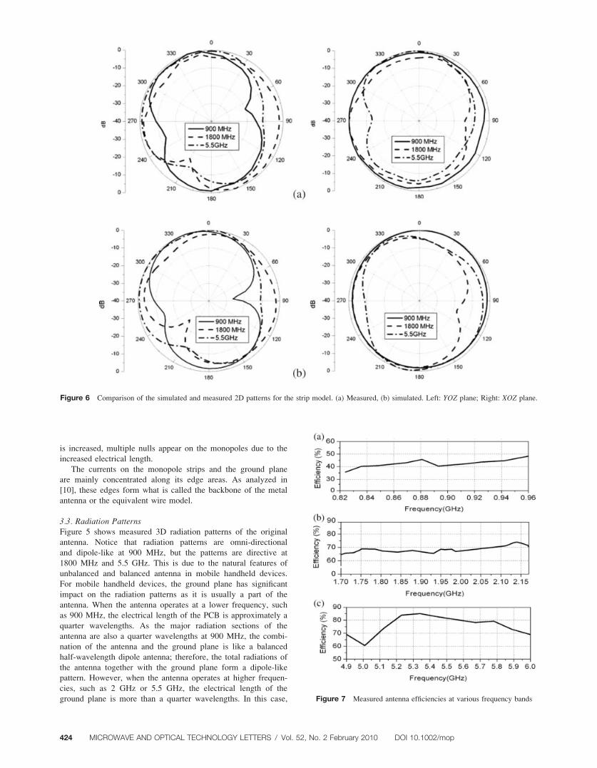
Figure 6 Comparison of the simulated and measured 2D patterns for the strip model. (a) Measured, (b) simulated. Left: YOZ plane; Right: XOZ plane.
Figure 7 Measured antenna efficiencies at various frequency bands
424 MICROWAVE AND OPTICAL TECHNOLOGY LETTERS / Vol. 52, No. 2 February 2010 DOI 10.1002/mop
the ground plane and other radiation elements are more like an
antenna array. As mentioned in the previous section, the antenna
has multiple current nulls on the radiation strips at 1.8 and
5.5 GHz; this makes the antenna more like an unbalanced radia-
tor. Therefore, it is impossible to get a dipole-like pattern at
higher frequencies.
Figure 6 displays comparison of the simulated and measured
patterns in the two principal planes (ZOX and ZOY) at 900 MHz,
1.8 GHz, and 5.5 GHz. The antenna measurement was carried out
in an anechoic chamber at RIM. Good agreement is obtained.
3.4. Antenna EfficiencyThe total antenna efficiency is also measured, which is defined
as the ratio of the radiated power to the total power delivered to
the input terminal of the antenna. Thus, the efficiency includes
all impacts from mismatching loss, dielectric loss, and conductor
loss. Figure 7 plots the measured efficiency at several frequency
bands. It is found that the antenna achieved an efficiency of 45–
48% at the low frequency band from 824 to 960 MHz, an effi-
ciency of 68–75% at middle frequency band from 1.6 to
2.2 GHz, and an efficiency of 68–84% from 4.9 to 6 GHz.
4. CONCLUSION AND DISCUSSION
This article presents a folded multiple monopole antenna for
handheld device. The simulated and measured results show that
the designed antenna operates at almost all current frequency
bands from 800 MHz to 6 GHz. With a bending technology in
three dimensions, the folded antenna has been analyzed and pro-
totyped. The proposed antenna is much smaller in dimensions
while has better performances than conventional monopole
antennas for handset applications.
REFERENCES
1. W. Geyi, Physical limitations of antennas, IEEE Trans Antennas
Propag 51 (2003), 2116–2123.
2. T. Taga, Analysis of planar inverted-F antennas and antenna design
for portable radio equipment, In: K. Hirasawa and M. Haneishi
(Eds.), Analysis, design and measurement of small and low profile
antennas, Artech House, Boston, 1992, Chapter 5.
3. D.M. Nashaat, H.A. Elsadek, and H. Ghali, Single feed compact
quad-band PIFA antenna for wireless communication applications,
IEEE Trans Antennas Propag 53 (2005), 2631–2635.
4. S.Y. Lin, A low-profile folded planar monopole antenna for wire-
less communication, Microwave Opt Technol Lett 36 (2003),
46–48.
5. K.L. Wong, Very-low-profile monopoles for internal mobile phone
antennas, In: Planar antennas for wireless communications, Wiley
Series in Microwave and Optical Engineering, Hardcover, 2003.
6. W. Geyi, Q. Rao, S. Ali, and D. Wang, Handset antenna design:
Practice and theory, Prog Electromagn Res PIER 80 (2008),
123–160.
7. Q. Rao and W. Geyi, Patch loaded tri-folded monopole strip
antenna, U.S. Patent Pending, ID32790
8. Q. Rao and W. Geyi, Ultra-small cubic folded strip antenna for
handset devices, 2008 AP-S IEEE Antennas Propag Soc Int Symp,
San Diego, CA (2008)
9. W. Geyi, J. Perry, and Y. Qi, Foster reactance theorems for anten-
nas and radiation Q, IEEE Trans Antennas Propag Ap-48 (2000),
401–408.
10. FEKO, Available at: http:/info.feko.com.
VC 2009 Wiley Periodicals, Inc.
INTEGRATED WIDE–NARROW BANDANTENNA FOR MULTIBANDAPPLICATIONS
E. Ebrahimi and P. S. HallDepartment of Electronic, Electrical and Computer Engineering,School of Engineering, University of Birmingham, Edgbaston ParkRoad, Birmingham B15 2TT, United Kingdom; Correspondingauthor: [email protected]
Received 18 May 2009
ABSTRACT: In this article, a novel integration concept is introducedfor multiband antennas. An integrated wide–narrow band antenna ispresented, which is composed of a shorted microstrip patch integrated
to a coplanar waveguide fed ultrawideband monopole antenna. Thepatch is printed on the reverse side of the substrate using the monopole
antenna as a ground plane. A prototype of the antenna is fabricated andverified. This antenna adds the possibility to operate in two of differentstandards or frequency bands at any given time. VC 2009 Wiley
Periodicals, Inc. Microwave Opt Technol Lett 52: 425–430, 2010;
Published online in Wiley InterScience (www.interscience.wiley.com).
DOI 10.1002/mop.24926
Key words: CPW-fed antenna; integrated antenna; multiband antenna;ultrawideband (UWB) antenna
1. INTRODUCTION
Antenna design is becoming a bottleneck for wireless mobile
devices where multiple communication services are integrated in
the same piece of hardware. Today, a typical cellular phone can
have multiple services such as GPS, DCS, BT, and WLAN that
all rely on a multiband antenna. On the other hand, now-a-days
laptops accommodate several antennas for services such as
WLAN, BT, ultrawideband (UWB), and DVB-H. Implementing
the multiband/standard antennas in a small terminal is challeng-
ing due to the limited space and low-cost requirements [1–4].
Accordingly, antennas used for such devices must also follow
downsizing trend of the terminal unit. In particular, smaller
built-in antennas are required at present.
Different techniques are documented to design multiband/
standard antennas. One method that is widely used for handset
antennas is the use of meandered metal segments. In this
method, the meandering is achieved by cutting slots in nonra-
diating edges of the antenna [5, 6]. This effectively elongates
the surface current path on the antenna and increases the load-
ing, which results in another mode of operation. However, for
nonresonating antennas like the UWB antennas that radiate in a
wide frequency, this technique is not applicable. Another
approach of designing antennas for multiband/standard terminals
is to use separate antennas for any operation mode. This tech-
nique while having multiple ports may require more space.
Therefore, integrating several antennas in limited space is very
challenging.
In this article, the novel integration technique for multiband
antennas is introduced. To demonstrate this concept, an inte-
grated wide–narrow band antenna is presented. The proposed
structure is composed of a shorted microstrip patch, which is
integrated to a coplanar waveguide (CPW) fed UWB monopole
antenna. The patch is fed through a tapered microstrip line and
printed on the reverse side of the substrate, using the monopole
antenna as a ground plane. A prototype of the antenna is fabri-
cated and verified. The antenna has excellent impedance match-
ing, stable radiation patterns, and linear group delay over the
entire UWB along with good-impulse response. This antenna
DOI 10.1002/mop MICROWAVE AND OPTICAL TECHNOLOGY LETTERS / Vol. 52, No. 2 February 2010 425