Embed Size (px)
Citation preview

Version.1.1 November 2013 Company Confidential Copyright © 2013 Wormald Page 0 of 62
Foam Water Spray Vehicle Fire Suppression System Loss of Pressure Operation & Maintenance Manual

Version.1.1 November 2013 Company Confidential Copyright © 2013 Wormald Page 1 of 62
Contents PREFACE ................................................................................................................................................... 3
1.0 INTRODUCTION ............................................................................................................................. 4
2.0 LOSS OF PRESSURE SYSTEM ..................................................................................................... 5
2.1 System Operation ........................................................................................................................ 5
2.2 Components ................................................................................................................................. 6
2.2.1 Agent Storage Assembly .......................................................................................................... 6
2.2.1 a) Storage Container ............................................................................................................. 6 2.2.1 b) Refill Plug .......................................................................................................................... 7 2.2.1 c) Container Control Valve - Loss of Pressure System ......................................................... 8 2.2.1 d) Container Brackets ............................................................................................................ 9 2.2.1 e) Base Plate ....................................................................................................................... 10 2.2.1 f) Container Siphon Tube Flexible ...................................................................................... 10
2.2.2 Actuators, Fire Panels and Pressure Switches....................................................................... 11
2.2.2 a) Manual Actuation ............................................................................................................. 11 2.2.2 b) Solenoid Actuation .......................................................................................................... 12 2.2.2 c) Automatic Actuation – Linear Pneumatic Detection Tube ............................................... 12 2.2.2 d) Status Indicator Panel ..................................................................................................... 13 2.2.2 e) Pressure Switch .............................................................................................................. 13 2.2.2 f) Manifold Block ................................................................................................................. 14
2.2.3 Delivery Network .................................................................................................................... 14
2.2.3 a) Nozzle, Blow Off Cap and Bracket .................................................................................. 14 2.2.3 b) Hydraulic Hose and Stainless Steel Tube ....................................................................... 15 2.2.3 c) Fittings ............................................................................................................................. 15
3.0 IN CASE OF FIRE ......................................................................................................................... 16
3.1 Explanation ................................................................................................................................ 16
3.2 What to Expect ........................................................................................................................... 16
3.3 After the Fire is Out .................................................................................................................... 16
4.0 RECHARGE PROCEDURE .......................................................................................................... 17
4.1 General ...................................................................................................................................... 17
4.2 VFS Recharge Safety Tools ....................................................................................................... 17
4.3 Automatic Detection and Actuation Instructions ......................................................................... 17
4.4 Recharge Instructions – 25, 45, 65 and 106 Litre Systems ........................................................ 18
4.4.1 General ................................................................................................................................... 18
5.0. INSPECTION AND TESTING PROCEDURE ................................................................................ 22
5.1 Level A – Daily or 8 to 12 Hours Operation ................................................................................ 22
5.2 Level 1 – Six Monthly ................................................................................................................. 22
5.2.1 Cabin / Internal / External & Electric Actuation ....................................................................... 22
5.2.2 Container and Valve Assembly .............................................................................................. 22
5.2.3 Hose, Stainless Steel Tube and Fittings ................................................................................. 23
5.2.4 Nozzle and Blow Off Caps ...................................................................................................... 23
5.2.5 Pressure Switch ...................................................................................................................... 23
5.2.6 Status Indicator Panel ............................................................................................................ 23
5.2.7 Linear Pneumatic Detection Tube .......................................................................................... 24
5.2.8 Ancillary Visual / Audible Alarms ............................................................................................ 24

Revision 1.1 November 2013 Company Confidential Copyright © 2013 Wormald Page 2 of 36
5.2.9 Record on Record of Service Sheet ....................................................................................... 24
5.3 Level 2 – Yearly ......................................................................................................................... 24
5.3.1 Record on Record of Service Sheet ....................................................................................... 25
5.4 Level 4 – Five Yearly .................................................................................................................. 25
5.4.1 Record on Record of Service Sheet ....................................................................................... 25
6.0 RECORD OF SERVICE SHEET ................................................................................................... 25
7.0 WARRANTY .................................................................................................................................. 26
8.0 APPENDIX ..................................................................................................................................... 27
8.1 Product ....................................................................................................................................... 27
8.1.1 Assemblies ............................................................................................................................. 27
8.1.2 Individual Components ........................................................................................................... 29
8.1.3 VFS Safety Tools .................................................................................................................... 31
8.2 Detection Tube Fluid Chemical Resistance ............................................................................... 31
8.3 Sample of Record of Service (ROS) Sheet ................................................................................ 35
Version.1.1 November 2013 Company Confidential Copyright © 2013 Wormald Page 3 of 62
PREFACE
This Manual is intended to provide interpretation on the system componentry / operations, recharge process, and inspection / test procedures of the Wormald “Loss of Pressure” Vehicle Foam Water Spray Vehicle Fire Suppression Systems. Personnel, who operate, recharge, inspect or maintain these fire suppression systems, should read this entire manual.
As with Fire Protection, the “Loss of Pressure” Foam Water Spray Fire Suppression System requires periodic maintenance to help ensure that it will operate effectively and safely. Inspection frequency should be based on the need of the vehicle on which the System is installed. Maintenance should be conducted at intervals no longer than six months and follow the maintenance procedures in Section 5 of this Manual.
The Wormald “Loss of Pressure” Vehicle Foam Water Spray Fire Suppression System is limited to the uses described herein. For other applications, contact your Technical Services Group for advice.
As an operation, recharging and maintenance document, this manual is for information purposes only to assist the reader in understanding the operation and maintenance requirements for this type of Fire Suppression System.
Only competent accredited Wormald staff should carry out the recharge and maintenance of a Wormald “Loss of Pressure” Vehicle Foam Water Spray Vehicle Fire Suppression System. Advice and assistance should be sought from Wormald.
COPYRIGHT
The content of this Manual is the exclusive property of Wormald and is protected by copyright laws. No part of this Manual maybe reproduced, photocopied, stored on a retrieval system, or transmitted without the prior written consent of Wormald.
Version.1.1 November 2013 Company Confidential Copyright © 2013 Wormald Page 4 of 62
1.0 INTRODUCTION
The Wormald “Loss of Pressure” Vehicle Foam Water Spray Fire Suppression System is a pre-engineered fixed nozzle installation for protection of specialised vehicles and equipment. Typical applications include surface mining equipment, underground mining machines, forestry machines, construction equipment, waste disposal and agricultural machinery.
The Wormald “Loss of Pressure” Vehicle Foam Water Spray Fire Suppression (VFS) System consists of three major components; firstly, a pressurised agent storage container assembly containing 6% Aqueous Film Forming Foam (AFFF) concentrate mixed with potable water and pressurised with dry nitrogen to 1620 kPa at 20oC; secondly, a detection and actuation system to trigger the installation; and thirdly, a delivery network to carry the foam solution from the pressurised container to the nozzles and onto the fire. The VFS System is effective on Class A (carbonaceous materials) and Class B (flammable liquid) Fires and limited Class E Fires.
The system would be expected to perform effectively in environmental temperatures between 2°C and 60°C.
The VFS System can be actuated manually by the cabin actuator or the ground/external level actuator. Automatic Detection and Actuation are also available.
The extinguishing agent, AFFF foam solution, is delivered from a container pressurised with dry nitrogen through the hydraulic hose / stainless steel tube network and pre-set (non - aspirating) nozzles onto the fire prone surfaces/areas. The foam nozzles provide direct impingement and coverage at the selected fire risks in the risk area to be protected.
The Wormald ‘Loss of Pressure’ Vehicle Foam Water Spray Fire Suppression System is Activfire listed to be compliant with Australian Standard AS5062-2006: Fire protection for mobile and transportable equipment.
Note that NO substitution of any components is allowed as it will void the Activfire listing.

Revision 1.1 November 2013 Company Confidential Copyright © 2013 Wormald Page 5 of 36
2.0 LOSS OF PRESSURE SYSTEM
2.1 System Operation
The system operates when pressure is relieved from the container control valve.
(4) Control Valve
(1) Cabin Actuator with Gauge
(2) Ground Actuator
(2) Ground Actuator with Gauge
(5) Pressure Switches
(3) Detection Tube 180°C
(6) Nozzles
Status Indicator Panel
Stainless Steel
Tube Ringmain
The container control actuation hose and the detection tube are manually pressurised on site with nitrogen to maintain pressure on the control valve to retain the valve in a closed position.
The nitrogen pressure in the actuation hose and the detection tube can be released by operation of the manual actuators (1) or (2), or automatically by the detection tube (3) rupturing. Release of the nitrogen pressure allows the pressure in the container to open the control control valve (4) and discharge the foam solution from the nozzles (6).
Two pressure switches (5) that operate on loss of pressure are fitted in the actuation hose manifold block between the container control valve and the actuators. These pressure switches confirm system low pressure and system discharge with engine shutdown.
Revision 1.1 November 2013 Company Confidential Copyright © 2013 Wormald Page 6 of 36
2.2 Components
2.2.1 Agent Storage Assembly
2.2.1 a) Storage Container
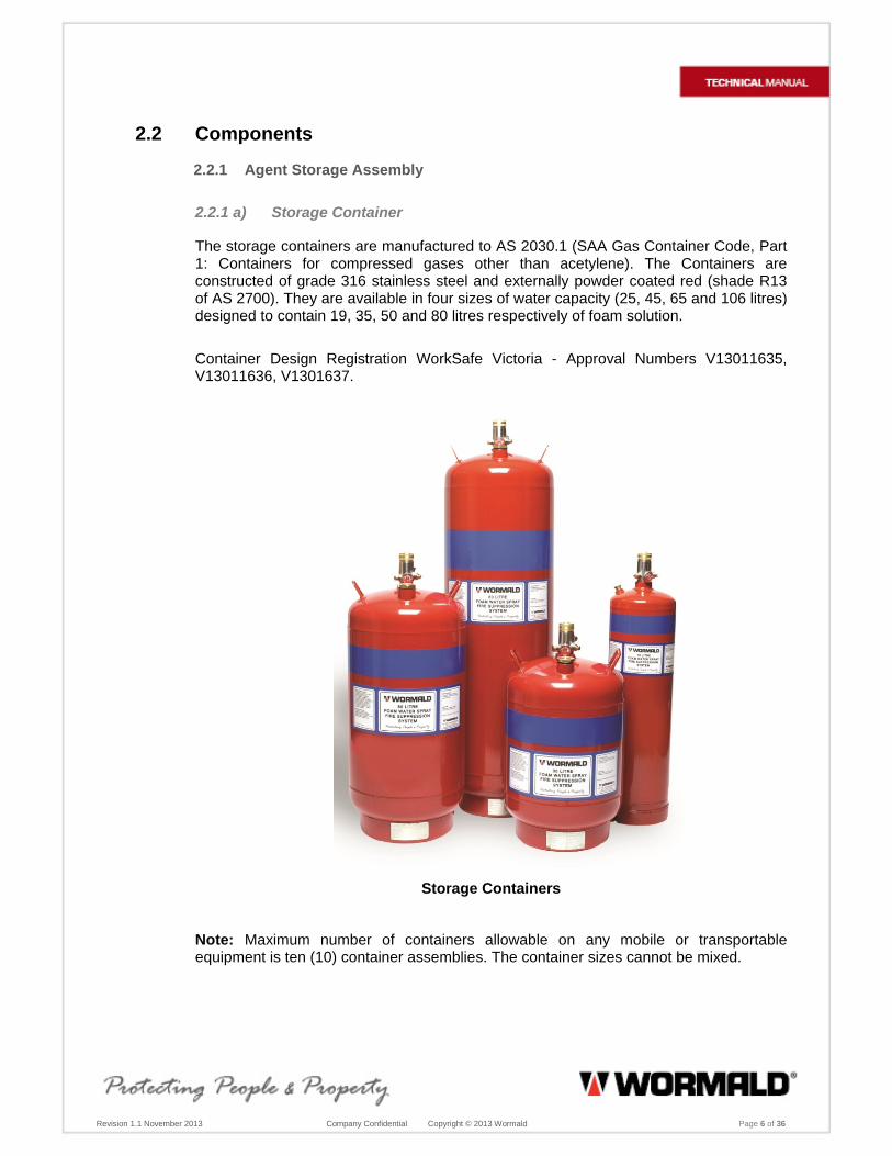
The storage containers are manufactured to AS 2030.1 (SAA Gas Container Code, Part 1: Containers for compressed gases other than acetylene). The Containers are constructed of grade 316 stainless steel and externally powder coated red (shade R13 of AS 2700). They are available in four sizes of water capacity (25, 45, 65 and 106 litres) designed to contain 19, 35, 50 and 80 litres respectively of foam solution.
Container Design Registration WorkSafe Victoria - Approval Numbers V13011635, V13011636, V1301637.
Storage Containers
Note: Maximum number of containers allowable on any mobile or transportable equipment is ten (10) container assemblies. The container sizes cannot be mixed.

Version.1.1 November 2013 Company Confidential Copyright © 2013 Wormald Page 7 of 62
Container Details
Container Size Container Part Number
Height Diameter Foam Solution
Label Part Number
106 Litre Container FO106LCYL 1210 mm 360 mm 80 litre FO106LABEL
65 Litre Container FO65LCYL 910 mm 360 mm 50 litre FO65LABEL
45 Litre Container FO45LCYL 690 mm 360 mm 35 litre FO45LABEL
45 Litre Container FO45LCYLHP 760 mm 318 mm 35 litre FO45LABEL
25 Litre Container FO25LCYL 910 mm 216 mm 19 litre FO25LABEL
2.2.1 b) Refill Plug
The refill plugs are manufactured from brass for all the container sizes. On the 45, 65 and 106 Litre Containers, an 'O' Ring is fitted to the Plug to obtain an effective seal between the Container and the Plug.
Part Number: FO50PLUG
Refill Plug (complete with ‘O’ Ring) for 45, 65 and 106 Litre Containers
Part Number: FO20PLUG
Refill Plug for 25 litre Container

Version.1.1 November 2013 Company Confidential Copyright © 2013 Wormald Page 8 of 62
2.2.1 c) Container Control Valve - Loss of Pressure System
This Container Control Valve is a high flow, single action pressure differential piston valve. The actuation of the container control valve is dependent on the release of nitrogen pressure in the actuation hose that maintains the container control valve in the normally closed position. This valve can only be used with the container mounted in the vertical position.
Incorporated into the container control valves are a pressure gauge, a burst disc and a Schrader pressurising valve. The valve stem has a 32nb BSP parallel thread fitted with a nitrile “O” Ring that seals in the container neck ring. The Container Control Valve is factory assembled and set, and must be returned to the manufacturer for any repairs.
The control valve is available as a combination of 304 Stainless Steel and Brass Valve, or as a fully 316 Stainless Steel Valve for regions where the water has a high saline content.
Valve Specification Valve Body 304 or 316 Stainless Steel Valve Cap Brass or 316 Stainless Steel Sealing Piston Assy Stainless Steel with Nitrile 'O'-ring seals Mass (Valve Assy) 1.5 kg Valve Operating Pressure 1620 kPa @ 20°C Burst Disc Rated Pressure 3100 kPa - 3500 kPa Discharge Outlet Thread 1 1/16” JIC Male Actuation Inlet Thread 1/4” BSP Female parallel Valve Stem Thread 32nb BSP Male parallel
Container Control Valve
Part Number Description
FOAMCHEAD Control Valve - Type C – Brass Cap
FOSSCHEAD Control Valve - Type C– Stainless Steel Cap
FOLIQGAUGE Liquid Filled Pressure Gauge
FOSCHVAL Schrader Valve
FO50ORING Container Valve 'O' Ring
BURDISASS Bursting Disc Assembly

Version.1.1 November 2013 Company Confidential Copyright © 2013 Wormald Page 9 of 62
2.2.1 d) Container Brackets
Container brackets are of the saddle type with a front clamp. The brackets are constructed of mild steel for each container size and are powder coated red to match the container. Brackets may be either welded or bolted to the vehicle structure. Specially designed brackets are available on request.
Part Number: FO106BKTS 106 Container Shielded Bracket
Part Number: FO65BKTS 65 Container Shielded Bracket
Part Number: FO45BKTS 45 Container Shielded Bracket
Part Number: FO25BKTS 25 Container Shielded Bracket
Brackets that are shown include the 106L and 65L. The 65L Bracket typically represents the 45L and 25L Bracket with a single clamp which fits around the Container.
A bracket is not available for the 45L HP - High Profile Container. This container was developed for the Forestry Industry and is supplied and installed within a fully enclosed box complete with a cover plate.
Part Number: FO45BOX 45 High Profile Container Box

Revision 1.1 November 2013 Company Confidential Copyright © 2013 Wormald Page 10 of 36
2.2.1 e) Base Plate
The base plate is available for mounting under the 45L, 65L and 106L Brackets. The base plate is manufactured from mild steel and has five (5) x 10 mm tapped holes in the plate. Two base plates are available. The shaped base plate has the same configuration of the container bracket base and should be utilised on Dozers, Loaders, Graders, etc. The round base plate should be utilised on the ‘deck’ of trucks or excavators to prevent any ‘stressing’ of the ‘deck’ plate.
Part Number: FOBASEPL Shaped Base Plate for 45L, 65L and 106L
Part Number: FOBASEPL-R Round Base Plate for 45L, 65L and 106L
2.2.1 f) Container Siphon Tube Flexible
The siphon tube has a ball joint fitted to the adaptor to enable the siphon to swivel within the container. This allows “pick up” of all the foam solution when the vehicle is on sloping terrain. The end of the siphon tube has a brass insert with an ‘O’-Ring fitted so the siphon tube will not wear on the inside wall of the stainless steel container.
Part Number Component
FODNTU106 Siphon Tube, 106L
FODNTU65 Siphon Tube, 65L
FODNTU45HP Siphon Tube, 45LHP
FODNTU45 Siphon Tube, 45L
FODNTU25 Siphon Tube, 25L

Version.1.1 November 2013 Company Confidential Copyright © 2013 Wormald Page 11 of 62
2.2.2 Actuators, Fire Panels and Pressure Switches
Each System requires at least one manual actuator. Options include the Cabin type for installation in the vehicle's operator compartment, as well as an internal / external actuator for access outside the vehicle and at ground level. Optional visual and audible alarms are available for discharge of Fire Suppression System.
2.2.2 a) Manual Actuation
The Manual Actuator is manufactured from brass with a stainless steel centre puncture pin (an all stainless steel unit is available for more aggressive environments). The centre pin has three o-rings which are located on the shaft. The top ‘0’-Ring is a seal to prevent any ingress of dust while the two lower o-rings are pressure seals.
There are two types of actuators. One actuator is manufactured with a gauge. The other actuator has no gauge and is best used in ‘high risk’ areas where a gauge may be prone to accidental damage.
Actuator hose (system) pressure can then be determined by using the Status Indicator Panel that is installed in the operator’s cabin.
The strike knob mounted on top of the centre pin is coloured red for easy identification. A safety pull pin is inserted in the actuator shaft and secured with an anti-tamper seal locking the actuator in the set position. The safety pull pin is secured to the knob by a stainless steel cable.
Cabin or Ground Actuator with Gauge
Part Number Component
FOACTVALVE Actuator Valve with Gauge - Brass
FOACTVALNN Actuator Valve without Gauge - Brass
FOSSACTVAL Actuator Valve with Gauge - Stainless Steel
FOSSACTVNN Actuator Valve without Gauge – Stainless Steel
FOACTBKT Actuator Bracket
FOLIQGAUGE Gauge
FOACTLABEL Actuator Label
Version.1.1 November 2013 Company Confidential Copyright © 2013 Wormald Page 12 of 62
2.2.2 b) Solenoid Actuation
The solenoid can be interconnected into the control valve actuation hose or the manifold block, and used on machines that require remote actuation via a transmitter / receiver or a ‘hard wired’ remote actuation device.
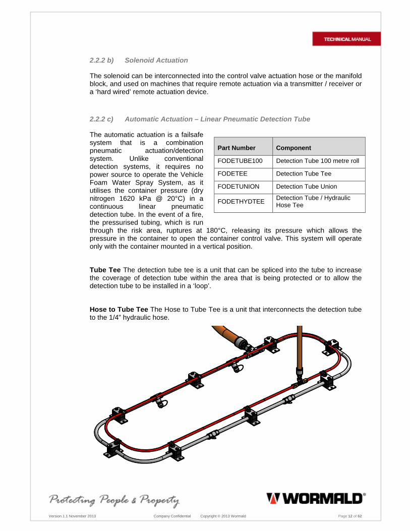
2.2.2 c) Automatic Actuation – Linear Pneumatic Detection Tube
The automatic actuation is a failsafe system that is a combination pneumatic actuation/detection system. Unlike conventional detection systems, it requires no power source to operate the Vehicle Foam Water Spray System, as it utilises the container pressure (dry nitrogen 1620 kPa @ 20°C) in a continuous linear pneumatic detection tube. In the event of a fire, the pressurised tubing, which is run through the risk area, ruptures at 180°C, releasing its pressure which allows the pressure in the container to open the container control valve. This system will operate only with the container mounted in a vertical position.
Tube Tee The detection tube tee is a unit that can be spliced into the tube to increase the coverage of detection tube within the area that is being protected or to allow the detection tube to be installed in a ‘loop’.
Hose to Tube Tee The Hose to Tube Tee is a unit that interconnects the detection tube to the 1/4” hydraulic hose.
Part Number Component
FODETUBE100 Detection Tube 100 metre roll
FODETEE Detection Tube Tee
FODETUNION Detection Tube Union
FODETHYDTEE Detection Tube / Hydraulic Hose Tee
Revision 1.1 November 2013 Company Confidential Copyright © 2013 Wormald Page 13 of 36
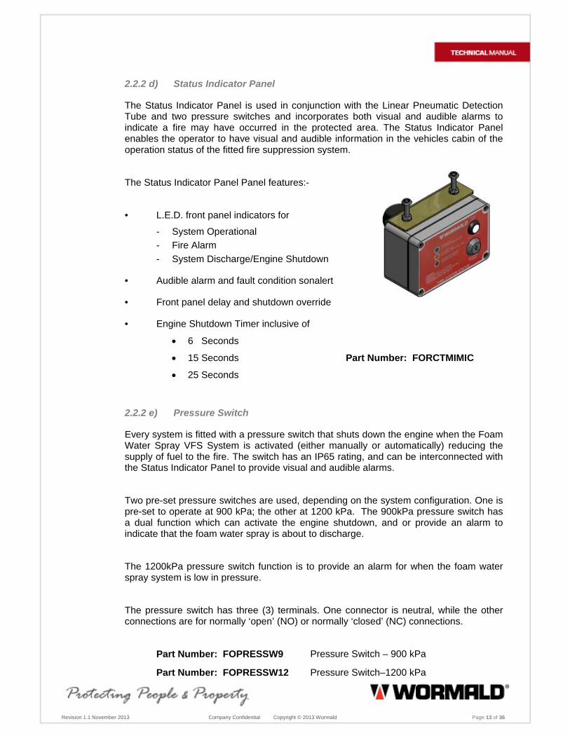
2.2.2 d) Status Indicator Panel
The Status Indicator Panel is used in conjunction with the Linear Pneumatic Detection Tube and two pressure switches and incorporates both visual and audible alarms to indicate a fire may have occurred in the protected area. The Status Indicator Panel enables the operator to have visual and audible information in the vehicles cabin of the operation status of the fitted fire suppression system.
The Status Indicator Panel Panel features:-
• L.E.D. front panel indicators for
- System Operational
- Fire Alarm
- System Discharge/Engine Shutdown
• Audible alarm and fault condition sonalert
• Front panel delay and shutdown override
• Engine Shutdown Timer inclusive of
6 Seconds
15 Seconds Part Number: FORCTMIMIC
25 Seconds
2.2.2 e) Pressure Switch
Every system is fitted with a pressure switch that shuts down the engine when the Foam Water Spray VFS System is activated (either manually or automatically) reducing the supply of fuel to the fire. The switch has an IP65 rating, and can be interconnected with the Status Indicator Panel to provide visual and audible alarms.
Two pre-set pressure switches are used, depending on the system configuration. One is pre-set to operate at 900 kPa; the other at 1200 kPa. The 900kPa pressure switch has a dual function which can activate the engine shutdown, and or provide an alarm to indicate that the foam water spray is about to discharge.
The 1200kPa pressure switch function is to provide an alarm for when the foam water spray system is low in pressure.
The pressure switch has three (3) terminals. One connector is neutral, while the other connections are for normally ‘open’ (NO) or normally ‘closed’ (NC) connections.
Part Number: FOPRESSW9 Pressure Switch – 900 kPa
Part Number: FOPRESSW12 Pressure Switch–1200 kPa

Revision 1.1 November 2013 Company Confidential Copyright © 2013 Wormald Page 14 of 36
2.2.2 f) Manifold Block
The brass manifold block is fitted with a mounting plate for attaching the manifold block to the machine through welding, tapping or bolting. Two manifold blocks are available.
The manifold block for pressure switches can locate the 1200kPa & 900 kPa pressure switches within the block. The manifold block has two ¼” BSP (F) inlets which allow the actuation hose to be connected within the actuation system. The manifold block for pressure switches shall be mounted as close as possible to the Status Indicator Panel.
The manifold block for the actuators can be located at a central point or adjacent to the Container Containers. All manifold blocks have the same fittings for ease of mounting. This manifold has six ¼” BSP (F) inlets which allows up to four actuators to connected.
Part Number: FOMANIFOLD Manifold Block for Actuators
2.2.3 Delivery Network
2.2.3 a) Nozzle, Blow Off Cap and Bracket
The nozzle is a full cone, non-aspirating spray type nozzle manufactured from brass (a stainless steel model is available for corrosive environments). The conical spray pattern is achieved with internal swirl plates. The nozzles are located in a closed ring main and directed to discharge onto the fire prone surfaces/areas, such as turbo chargers, exhaust manifolds, starter motors and any other areas that could be a source of ignition.
A blow off cap is supplied with the each nozzle to prevent external foreign matter from blocking the nozzle orifice. The Blow Off Cap is manufactured of stainless steel and includes a stainless steel wire connection fitted around the nozzle. Dow Corning #4 Silicon Grease should be applied to the
nozzle to assist the blow off cap in the prevention of external foreign matter blocking the nozzle.
On system discharge the blow off cap is thrown free of the nozzle, and the wire connection retains the blow off cap for further use.
Part Number Component
FOBNM16NOZ Nozzle– Brass
FOSS16NOZ Nozzle– Stainless Steel
FOSSCAP Blow Off Cap
FONOZBKT Nozzle Bracket

Revision 1.1 November 2013 Company Confidential Copyright © 2013 Wormald Page 15 of 36
The nozzle bracket is manufactured from 3 mm thick mild steel and secured to the vehicle structure by welding, self-tapping screws or nuts and bolts. The nozzle bracket is adjusted to aim the nozzle at the target. Corrosion protection (cold galvanising or similar) is to be applied after installation.
2.2.3 b) Hydraulic Hose and Stainless Steel Tube
The minimum pressure rating for hydraulic hose and fittings is SAE 100R1. For underground mining applications, the hydraulic hose must comply with VSBM, MSHA 2G-11C and all other SAE requirements including an operating temperature ranging from -54°C (-65°F) to 121°C (250°F). The stainless steel tubing meets the appropriate minimal ratings of DIN 17440, 2391 and 2413.
2.2.3 c) Fittings
Only Hose fittings, tees and connectors that are manufactured from steel and zinc dichromate electro plated for corrosion protection can be used in the VFS System.

Version.1.1 November 2013 Company Confidential Copyright © 2013 Wormald Page 16 of 62
3.0 IN CASE OF FIRE
When a fire event occurs, the response of the operator is very important. As soon as a fire is observed, the following actions should be taken:
1. Turn the machine engine off.
2. Actuate the Wormald foam water spray VFS System by pulling the ring pin and pushing down the plunger knob on the actuator. If the machine is fitted with an automatic detection system, system discharge may have already been initiated.
3. Move away from the vehicle/machine. Take a portable extinguisher if available.
4. Stand by with a portable extinguisher.
3.1 Explanation
If vehicle/machine is left running, it may add fuel to the fire and or the fire may re-ignite.
React quickly so the fire is caught before it grows too large.
Leave the fire area immediately to gain protection from windblown flames, potential explosions or other dangers created by the fire.
Heat remaining from the fire could cause re-ignition after the Wormald VFS System has discharged. It is important that operator or colleague stand by, at a safe distance, with a portable extinguisher.
This stand-by should be maintained until all possibility of re-ignition is assured.
3.2 What to Expect
When the Wormald VFS System discharges, there is a spray of foam solution over the protected area(s). The agent is non-toxic, wets, cools and forms a film of foam over the protected surfaces.
3.3 After the Fire is Out
The vehicle or machinery should not be restarted until the cause of the fire has been determined and it is deemed safe to move the vehicle/machinery without further protection by an operational fire suppression system. Once the cause of the fire is determined and repaired, immediately arrange to have the fire suppression system recharged.

Version.1.1 November 2013 Company Confidential Copyright © 2013 Wormald Page 17 of 62
4.0 RECHARGE PROCEDURE
4.1 General
Prior to the recharging of any System, the system pressure status of the System Container must be established.
The Container will require periodic internal and external examination and hydrostatic pressure testing by an authorised Gas Container Test Station. The test interval should not exceed five (5) years after the latest test date stamped on the container.
Many Systems have Automatic Detection and Actuation. Section 3 provides procedures for the Automatic Detection and Actuation and Section 5 for recharging the fire suppression systems.
4.2 VFS Recharge Safety Tools
To carry out Recharging of the fire suppression system correctly and safely, personnel require the VFS Safety Tools as a minimum. See details in Appendix on Safety Tools
Tools shall include:-
Vehicle System Charging Rig Part Number: FOCHARGERIG30
Pressure Test Tool for 1/4" Actuation Hose Part Number: FOPRESTESTC7031
Safety Cap with Isolation Valve and
Safety Vent Plug Part Number: FOSAFECAP7031
Overfill Tubes for each size container Part Numbers are: 106L:FOFILTUB106
65L: FOFILTUB65
45L: FOFILTUB45
25L: FOFILTUB25
4.3 Automatic Detection and Actuation Instructions
Check the Status Indicator Panel (SIP) to determine if the fire suppression system has discharged.
The Fire Panel will be displaying an audible alarm where the system has activated manually or automatically.

Revision 1.1 November 2013 Company Confidential Copyright © 2013 Wormald Page 18 of 36
Before performing the recharge steps, determine the cause of the system discharge.
In case of a fire or accidental discharge of the system, inspect linear pneumatic detection tube, the1/4” actuation hose, adaptors and the VFS components and connect the pressure test jig to confirm what has occurred.
a) Where the linear pneumatic detection tube has been damaged, if this is a small section that has been damaged, the linear pneumatic detection tube can be joined together using an detection tube union; however no more than two (2) connections can be fitted in the linear pneumatic detection tube and / or,
b) Check both the 900kPa and the 1200kPa Pressure Switches and where fitted into the manifold block or adaptors, check for leaks and / or
c) Check all manual actuators, adaptors and gauges if fitted. Any leaks within the actuator/s, remove the centre pin and replace with actuation o-ring kit and / or
d) Check all control valves, adaptors, gauge and schrader valve. Any leaks with or within the control valve, replace the external components where required, or if the leak is internal, replace with the piston o-ring kit and / or.
e) Check all stems and ferrules and adaptors on the actuation hose where leaks may occur
Note: Where leaks could occur, and components, adaptors, and /or stems on actuation hoses, remove any Lochtite on threads, clean threads and reapply with Lochtite 577 on the NPT, BSP, and JIC (M) threads
4.4 Recharge Instructions – 25, 45, 65 and 106 Litre Systems
4.4.1 General
Prior to the recharging of any System, the container pressure indicator / gauge must be established.
The Container will require periodic internal and external examination and hydrostatic pressure testing by an authorised Gas Container Test Station. The test interval should not exceed five (5) years after the latest test date stamped on the container.
1. Operate the actuator to ensure that the system has operated and is depressurised.
2. Carefully remove the Fill Plug from the shoulder of the extinguishing container.
Note: If audible release of gas is oberserved, do not fully remove the plug from the container until all pressure is released. This will be indicated when the audible release of gas ceases.
3. Inspect all Linear Pneumatic Detection Tube, and replace any broken or damaged sections. Do Not fit more than two connections to the Detection Tube

Revision 1.1 November 2013 Company Confidential Copyright © 2013 Wormald Page 19 of 36
4. Disconnect the Actuation Hose from the Control Valve and connect the Pressure Test Tool to the1/4” Actuation Hose pressurising the Hose to approximately 1000kpa for 3 minutes. Any Hoses that have been disconnected will need to be capped in order for the test to work correctly.
5. Disconnect Discharge Hose from lower port of the Container Control Valve and attach the Safety Cap with Isolation Valve and Safety Vent Plug to prevent any accidental discharges. Flush the Fire Suppression System with water through the discharge and distribution hoses and / or stainless steel tube to remove excess foam solution and any trapped debris.
6. During the discharge of water from the system, check the discharge from all Nozzles to ensure that they are not blocked, and the nozzle/s has a uniform spray pattern.
7. Recharge the Container through the control valve inlet.
8. Fit the correct overfill tube into the control valve inlet.
9. Add the appropriate quantity of potable water into the overfill tube. Once the correct amount of water has been filled into the container, remove the overfill tube and add the Ansul ICAO-B 6% AFFF foam concentrate to the container through the control valve inlet, as per Table 4.2.
Volume of Agent Foam
Solution (litres)Container
Volume (litres) Potable Water
(litres)
6% AFFF Concentrate
(litres)
19 25 17 2
35 45 31.5 3.5
50 65 45 5
80 106 72 8
Table 4.2
10. Once the water and foam concentrate has been added, check the siphon tube is properly connected to the control valve; that there is no wear and tear on or near the ball joint and that the o-ring on the end of the siphon tube is in place and not worn.
11. Remove the overfill tube and refit the Control Valve and siphon tube to the control valve port, tighten as required and re-connect the Discharge Hose to the outlet port of the Control Valve.

Revision 1.1 November 2013 Company Confidential Copyright © 2013 Wormald Page 20 of 36
12. Lightly lubricate the Fill Plug ‘O’ ring with #4 Dow Corning silicon lubricant, refit the Fill Plug to the Container, then “nip up” to ensure that it has made face to face contact with the Container collar fitting.
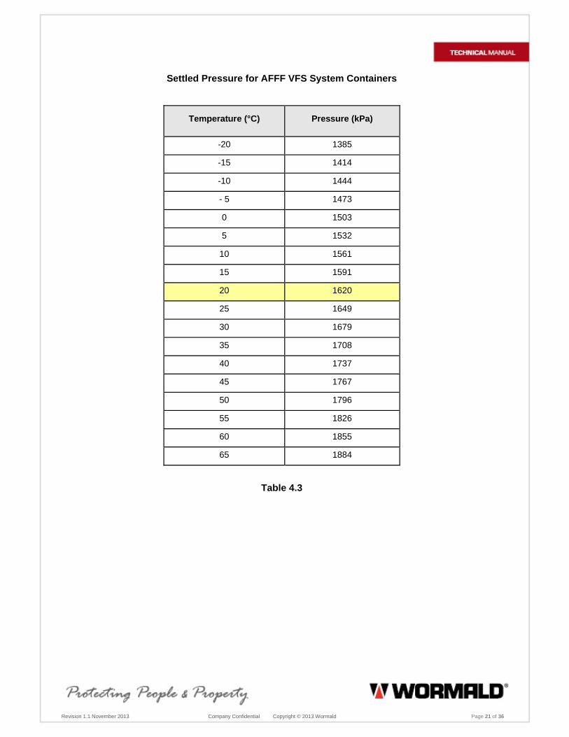
13. Pressurise the Container with dry nitrogen to 1620 kPa @ 20°C (Refer to Table 5.3) via the Schrader valve fitted to Container Control Valve.
Note: Use the Vehicle Systems Charging Rig (which has independent gauges, regulator and pressure relief valve) to pressurise system. A calibrated pressure gauge of the charge rig must be used in the nitrogen supply line to determine that the system pressure is 1620kPa @ 20°C. Do Not use the pressure gauge fitted to the Container Control Valve or pressure gauges on the Nitrogen Cylinder. When applying pressure to Container fitted with Control Valves through the Schrader valve, adjust the regulator so the gauge reads 1000 kpa and wait for bubbling reaction to settle in the container. Increase pressure rates at 200kpa intervals and do not exceed 2200kpa. At each 200kpa interval, wait to the bubbling reaction settles before proceeding to the next interval. After system has been pressurised to the correct pressure / temperature (see temperature chart – table 4.3), check that the Container Control Valve pressure gauge is reading within the green zone and to the nearest 50kpa increment on the high side.
14. Test all of the System connections for leaks using AFFF in water solution or ‘Blue’. Ensure all Hose and Detection fittings, Fill Plug, Control Valve connections, Schrader Valve and Gauge are tested.
15. Refit the dust cap to the Schrader valve.
16. Lubricate the nozzles with Dow Corning #4 silicon grease and refit the Blow Off Caps to all system nozzles.
17. Record details on Record of Service Sheet. See sample in the Appendix
Revision 1.1 November 2013 Company Confidential Copyright © 2013 Wormald Page 21 of 36
Settled Pressure for AFFF VFS System Containers
Temperature (°C) Pressure (kPa)
-20 1385
-15 1414
-10 1444
- 5 1473
0 1503
5 1532
10 1561
15 1591
20 1620
25 1649
30 1679
35 1708
40 1737
45 1767
50 1796
55 1826
60 1855
65 1884
Table 4.3

Revision 1.1 November 2013 Company Confidential Copyright © 2013 Wormald Page 22 of 36
5.0. INSPECTION AND TESTING PROCEDURE
Maintenance of the fire suppression system shall be undertaken as per the Inspection, Test, and Preventative Maintenance Schedules of AS 5062-2006 and the following:-
5.1 Level A – Daily or 8 to 12 Hours Operation
1. Check container pressure gauge are within the operating range.
2. Check the cabin status pressure gauge if fitted on the manual actuator assembly to ensure that it is in the correct operating range.
3. Ensure the safety pin and anti tamper tie are intact.
4. Inspect and ensure manual actuators are clean, undamaged and accessible.
5. System Status Indicator Panel determine all secure, clean undamaged and accessible.
5.2 Level 1 – Six Monthly
5.2.1 Cabin / Internal / External & Electric Actuation
1. Check the cabin, internal and external status pressure gauge where fitted on actuators and if below operating pressure, check for leaks.
2. Inspect general condition of each actuator.
3. Ensure the safety pin and anti tamper tie are intact.
4. Ensure labels are visible and legible.
5. Check for any leaks on 1/4" actuation hose fittings.
5.2.2 Container and Valve Assembly
1. Check condition of container assembly in accordance with Australian Standard AS 2030.1 and AS2337.1
2. Inspect the mounting bracket for any damage and ensure the container is tightly secured.
3. Check the pressure gauge on the container control valve to ensure it is in the operating range.
4. Check the Schrader valve cap is in place.
Revision 1.1 November 2013 Company Confidential Copyright © 2013 Wormald Page 23 of 36
5.2.3 Hose, Stainless Steel Tube and Fittings
1. Inspect all hoses and stainless steel tube for any abrasion or excessive wear.
2. Ensure that all hoses and stainless steel tube are firmly fastened.
3. Inspect all fittings for any damage or excessive wear.
4. Ensure that all fittings are firmly tightened.
a) Flush all hoses (except the 1/4" actuation hoses), stainless steel tube and nozzles with water.
b) Check 1/4” actuation hoses and linear pneumatic detection tube for any leaks.
5.2.4 Nozzle and Blow Off Caps
1. Inspect each nozzle bracket and nozzle direction is pointing to its aim point.
2. Remove the nozzle caps and check all nozzle outlets for debris and foreign materials.
3. Lubricate each nozzle with “Dow Corning #4” silicon grease and refit the nozzle caps - replace any damaged nozzles or caps.
5.2.5 Pressure Switch
1. Check the condition of the Pressure Switch.
2. Check that all wiring is properly connected.
3. Check the condition of all wiring.
5.2.6 Status Indicator Panel
1. Check the operational functions of the Status Indicator Panel.
2. Check the condition of Status Indicator Panel.
3. Check the shutdown time delay is operating correctly and within their defined period
4. Check the condition of the Engine Shutdown Override Switch.
5. Carry out a system test on Status Indicator Panel (See page 40)

Revision 1.1 November 2013 Company Confidential Copyright © 2013 Wormald Page 24 of 36
5.2.7 Linear Pneumatic Detection Tube
1. Check the condition of the Linear Pneumatic Detection Tube
2. Check for any Leaks at Unions and Tee Joints.
3. Check that the Linear Pneumatic Detection Tube does not have more than two connections otherwise. Replace the Linear Pneumatic Detection Tube if required.
4. Check that the Linear Pneumatic Tube is properly clamped.
5.2.8 Ancillary Visual / Audible Alarms
1. Where fitted check the condition of the visual and audible alarms.
2. Test the audible and visual to confirm that they are in good working order.
3. Check that the wiring between the audible and visual and the Status Indicator Panel and the un-isolated power supply are securely mounted and there is no damage to the cables.
5.2.9 Record on Record of Service Sheet
5.3 Level 2 – Yearly
1. Carry out Level 1 - Six monthly checks.
2. See Note below for Remote Control Function, if fitted, before carrying out the following procedures.
3. a) Discharge Test the Fire Suppression System and time the discharge to ensure it does not exceed, where the maximum permissible number of nozzles are fitted for a standard discharge of 60 seconds +/- 10%.
b) Discharge Test the Fire Suppression System and time the discharge to ensure it does not exceed, where the maximum permissible number of nozzles are fitted for an extended discharge of 90 seconds +/- 10%.
4. Replace foam solution in container. (Refer to Recharge Instructions)
5. Check and lubricate the 'O' Rings on the Filler Plug and Control Valve using Dow Corning #4 silicon grease.
6. Remove the Control Valve, lubricate ‘O’ Rings using Dow Corning #4 silicon grease and check the operation.
7. Check Engine Shutdown operation, discharge to release and the override switch functions.
8. Lubricate all nozzles using Dow Corning #4 silicon grease and refit the nozzle blow-off caps.
Revision 1.1 November 2013 Company Confidential Copyright © 2013 Wormald Page 25 of 36
5.3.1 Record on Record of Service Sheet
Note: If the Remote Control Function is interconnected with the Foam Fire Suppression System through a transmitter/receiver adaptor or cable connection, check and test the fire system by actuating the Fire System by Remote Control Operation and simulate a test of discharge utilising the Test Control Module.
5.4 Level 4 – Five Yearly
1. Carry out a Level 2 service.
2. In accordance with AS 2030.1, hydrostatic pressure test containers every five (5) years at an Australian Standards approved pressure test station container.
3. Where fitted, replace Linear Pneumatic Detection Tube every five (5) years, or in an aggressive environment, as required.
5.4.1 Record on Record of Service Sheet
Refer to sample in Appendix
6.0 RECORD OF SERVICE SHEET
It is important that each six monthly, twelve monthly and five yearly inspections, along with system discharges and hydrostatic container tests, be recorded on the Record of Service Sheet.
Revision 1.1 November 2013 Company Confidential Copyright © 2013 Wormald Page 26 of 36
7.0 WARRANTY
The components of the Wormald Vehicle Foam Water Spray Fire Suppression System supplied by the Wormald are warranted to you as the original purchaser for one year from the date of delivery against defects in workmanship and materials. Wormald will replace or repair any Wormald supplied component which, in its opinion, is defective and has not been tampered with or subjected to misuse, abuse, exposed to highly corrosive conditions or extreme high temperature provided that written notice of the alleged defect shall have been given to the Wormald within 30 days after discovery thereof and prior to the expiration of one year after delivery, and further provided that if Wormald so instructs, such article or part thereof is promptly returned to Wormald with shipping charges prepaid.
Disclaimer of Liability and Limitation of Damage
The above warranty is the only one given by Wormald concerning this system and applies only to the Wormald Vehicle Foam Water Spray Fire Suppression Systems that have been installed and maintained in accordance with all directions and requirements provided by Wormald in the Manual created for the type of system in operation. THIS WARRANTY IS IN LIEU OF ALL OTHER WARRANTIES WHETHER EXPRESSED OR IMPLIED, INCLUDING BUT NOT LIMITED TO FITNESS OR PURPOSE AND MERCHANTABILITY, AND WORMALD DOES NOT ASSUME, OR AUTHORISE ANY OTHER PERSON TO ASSUME FOR IT, ANY OTHER LIABILITY IN CONNECTION WITH THE SALE OF ITS PRODUCTS. WORMALD SHALL NOT BE LIABLE FOR CONSEQUENTIAL OR SIMILAR DAMAGES.
For repairs, parts and service of the Wormald Vehicle Fire Suppression System, contact your local Wormald representative, or Wormald, Unit 1, 2-8 South Street, Rydalmere, NSW Australia 2116.

Revision 1.1 November 2013 Company Confidential Copyright © 2013 Wormald Page 27 of 36
8.0 APPENDIX
8.1 Product
8.1.1 Assemblies
106LCYLASSC 106L Assembly with 'C' Valve & Flex Tube
PART NUMBER ASSEMBLY
FO106LCYL 106L Container
FO106LABEL 80L Label
FO106BKTS 106L Shielded Bracket
FODNTU106 Flex Syphon Tube - 106
FO50PLUG 50mm Plug for 45/65/106L Container
FOAMCHEAD Control Valve LOP
FOBAND3 Vivid Blue Band - Suit 106L Container
FOINCASE Label - In Case of Fire
FOWARNFOAM Foam Warning Label
65LCYLASSC 65L Assembly with 'C' Valve & Flex Tube
PART NUMBER ASSEMBLY
FO65LCYL 65L Container
FO65LABEL 50L Label
FO65BKTS 65L Shielded Bracket
FODNTU65 Flex Syphon Tube - 25/65
FO50PLUG 50mm Plug for 45/65/106L Container
FOAMCHEAD Control Valve LOP
FOBAND2 Vivid Blue Band - Suit 25L, 45HP & 65L Container
FOINCASE Label - In Case of Fire
FOWARNFOAM Foam Warning Label
45LCYLASSC 45L Assembly with 'C' Valve & Flex Tube
PART NUMBER ASSEMBLY
FO45LCYL 45L Container
FO45LABEL 35L Label
FO45BKTS 45L Shielded Bracket
FO50PLUG 50mm Plug for 45/65/106L Container
FODNTU45 Flex Syphon Tube - 16/45
FOAMCHEAD Control Valve LOP
FOBAND1 Vivid Blue Band - Suit 16L & 45L Container
FOINCASE Label - In Case of Fire
FOWARNFOAM Foam Warning Label

Revision 1.1 November 2013 Company Confidential Copyright © 2013 Wormald Page 28 of 36
45LHPASSC 45L Assembly with 'C' Valve & Flex Tube
PART NUMBER ASSEMBLY
FO45LCYLHP 45L Container High Profile
FO45LABEL 35L Label
FO45BOX 45L Box for HP 45L Container
FO50PLUG 50mm Plug for 45/65/106L Container
FODNTU45HP Flex Syphon Tube - 45 High Profile
FOAMCHEAD Control Valve LOP
FOBAND2 Vivid Blue Band - Suit 25L, 45HP & 65L Container
FOINCASE Label - In Case of Fire
FOWARNFOAM Foam Warning Label
25LCYLASSC 25L Assembly with 'C' Valve & Flex Tube
PART NUMBER ASSEMBLY
FO25LCYL 25L Container
FO25LABEL 19L Label
FO25BKTS 25L Shielded Bracket
FODNTU65 Flex Syphon Tube - 25/65
FO20PLUG 20mm Plug for 16/25L Container
FOAMCHEAD Control Valve LOP
FOBAND2 Vivid Blue Band - Suit 25L, 45HP & 65L Container
FOINCASE Label - In Case of Fire
FOWARNFOAM Foam Warning Label
NOZMETCAP Nozzle with Metal Cap
PART NUMBER ASSEMBLY
FOBNM16NOZ Nozzle
FOSSCAP Metal Blow Off Cap -Stainless
NOZASS Nozzle Ass with Metal Cap (Angle Bracket)
PART NUMBER ASSEMBLY
FOBNM16NOZ Nozzle
FOSSCAP Metal Blow Off Cap -Stainless
FONOZBKT Nozzle Bracket
ACTASSC Actuator Assembly for LOP System
PART NUMBER ASSEMBLY
FOACTLABEL Actuator Label - AS5062 Compliant
FOACTVALVE Actuator Valve with 1620kpa Gauge
FOACTBKT-LFG Actuator Bracket - Suit Actuator with Liquid Filled Gauge
Revision 1.1 November 2013 Company Confidential Copyright © 2013 Wormald Page 29 of 36
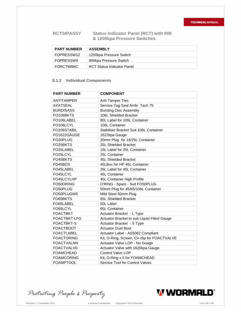
RCTSIPASSY Status Indicator Panel (RCT) with 900 & 1200kpa Pressure Switches
PART NUMBER ASSEMBLY
FOPRESSW12 1200kpa Pressure Switch
FOPRESSW9 900kpa Pressure Switch
FORCTMIMIC RCT Status Indicator Panel
8.1.2 Individual Components
PART NUMBER COMPONENT
ANTITAMPER Anti Tamper Ties AXATSEAL Service Tag Seal Ambi Tach 75 BURDISASS Bursting Disc Assembly FO106BKTS 106L Shielded Bracket FO106LABEL 80L Label for 106L Container FO106LCYL 106L Container FO106STABIL Stabiliser Bracket Suit 106L Container FO1622GAUGE 1622kpa Gauge FO20PLUG 20mm Plug for 16/25L Container FO25BKTS 25L Shielded Bracket FO25LABEL 19L Label for 25L Container FO25LCYL 25L Container FO45BKTS 45L Shielded Bracket FO45BOX 45LBox for HP 45L Container FO45LABEL 35L Label for 45L Container FO45LCYL 45L Container FO45LCYLHP 45L Container High Profile FO50ORING O'RING - Spare - Suit FO50PLUG FO50PLUG 50mm Plug for 45/65/106L Container FO50PLUGMS Mild Steel 50mm Plug FO65BKTS 65L Shielded Bracket FO65LABEL 50L Label FO65LCYL 65L Container FOACTBKT Actuator Bracket - L Type FOACTBKT-LFG Actuator Bracket to suit Liquid Filled Gauge FOACTBKT-S Actuator Bracket - S Type FOACTBOOT Actuator Dust Boot FOACTLABEL Actuator Label - AS5062 Compliant FOACTORING Kit, O-Ring, Screen, Cir-clip for FOACTVALVE FOACTVALNN Actuator Valve LOP - No Guage FOACTVALVE Actuator Valve with 1620kpa Gauge FOAMCHEAD Control Valve LOP FOAMCORING Kit, O-Ring x 5 for FOAMCHEAD FOAMPTOOL Service Tool for Control Valves

Revision 1.1 November 2013 Company Confidential Copyright © 2013 Wormald Page 30 of 36
PART NUMBER COMPONENT
FOBAND1 Vivid Blue Band - Suit 16L & 45L Containers FOBAND2 Vivid Blue Band - Suit 25L, 45HP & 65L Containers FOBAND3 Vivid Blue Band - Suit 106L Container FOBASEPL Base Plate - Shaped FOBASEPL-R Base Plate - Round FOBNM16NOZ Nozzle FOCLAMP Clamp Suit 45L 65L 106L Bracket FODETEE Union Tee (each) FODETGROM Detection Tube Grommet FODETHYDTEE Hydraulic Hose to Detection Tube Tee FODETUB100 Detection Tube 100 Metre Roll FODNTU45 Flex Syphon Tube - 16/45 FODNTU45HP Flex Syphon Tube - 45 High Profile FODNTU65 Flex Syphon Tube - 25/65 FODNTUORING O'ring - Spare - Suit Siphon Tubes FOHEADCAP Brass Cap to suit Control Valve FOHEADPIST Control Valve Piston & 'O' Ring Set FOINCASE Label - In Case of Fire FOKNOB Actuator Knob & Pull Pin FOLIQGAUGE 1620kpa Liquid Filled Gauge FOMANIFLOP Manifold Block LOP FOMANIFOLD Manifold Block1/4 BSPT x 6 Way FONOZBKT Nozzle Bracket FONOZBKTF Nozzle Bracket - Flat FOPRESSW12 Pressure Switch 1200KPA FOPRESSW9 Pressure Switch 900 kpa FORCTMIMIC RCT Status Indicator Panel FORCTTAILS 2 Metre Lead for RCT Panel FOSCHVAL Schrader Cap with Valve FOSIPMIMIC AME Status Indicator Panel FOSOLNOID Solenoid for Remote Loss of Pressure Actuation FOSS16NOZ Nozzle - 316 Stainless FOSS20PLUG 20mm Stainless Steel Plug for 16/25L Cyl FOSSACTVAL S/S Actuator Valve with Gauge FOSSACTVNN S/S Actuator Valve without Gauge FOSSCAP Metal Blow Off Cap -Stainless FOSSCHEAD Control Valve LOP 316 Stainless FOSYSACTLABEL Fire Suppression System Activation Label FOWARNFOAM Foam Warning Label G1620 1620kpa Gauge 79559 Alarm Horn – Audible Alarm 419208 Alarm Strobe – Visual Alarm 430042 AFFF 6% ICAO-B 20 Litre Drum NZFO106LABEL 106L Label - New Zealand with FERN Approval NZFO25LABEL 25L Label - New Zealand with FERN Approval NZFO45LABEL 45L Label - New Zealand with FERN Approval NZFO65LABEL 65L Label - New Zealand with FERN Approval
NZFO45HPLABEL 45L High Profile Label - New Zealand with FERN Approval
Revision 1.1 November 2013 Company Confidential Copyright © 2013 Wormald Page 31 of 36
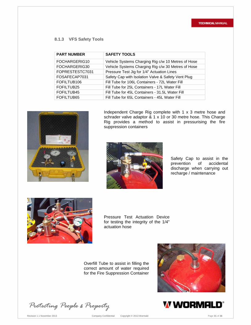
8.1.3 VFS Safety Tools
PART NUMBER SAFETY TOOLS
FOCHARGERIG10 Vehicle Systems Charging Rig c/w 10 Metres of Hose FOCHARGERIG30 Vehicle Systems Charging Rig c/w 30 Metres of Hose FOPRESTESTC7031 Pressure Test Jig for 1/4" Actuation Lines FOSAFECAP7031 Safety Cap with Isolation Valve & Safety Vent Plug FOFILTUB106 Fill Tube for 106L Containers - 72L Water Fill FOFILTUB25 Fill Tube for 25L Containers - 17L Water Fill FOFILTUB45 Fill Tube for 45L Containers - 31.5L Water Fill FOFILTUB65 Fill Tube for 65L Containers - 45L Water Fill
Independent Charge Rig complete with 1 x 3 metre hose and schrader valve adaptor & 1 x 10 or 30 metre hose. This Charge Rig provides a method to assist in pressurising the fire suppression containers
Safety Cap to assist in the prevention of accidental discharge when carrying out recharge / maintenance
Pressure Test Actuation Device for testing the integrity of the 1/4" actuation hose
Overfill Tube to assist in filling the correct amount of water required for the Fire Suppression Container

Revision 1.1 November 2013 Company Confidential Copyright © 2013 Wormald Page 32 of 36
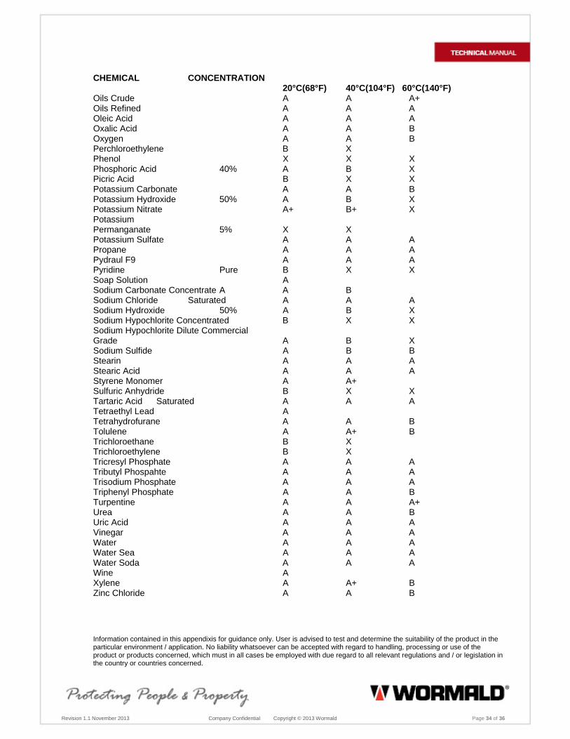
8.2 Detection Tube Fluid Chemical Resistance
In general, nylons exhibit a good resistance to bases, salt solutions, salt water, marine atmospheres, oils, greases and petroleum products. Nylon is not affected by electrolytic corrosion as found in and around salt water and industrial atmospheres. The resistance to mineral salts, organic acids and strong oxidizing agents varies with the chemical group involved, concentration and temperature. Use of Nylon products in chemical environments should be service tested to determine suitability. The same applies to mixtures of chemicals which alone do not attack Nylon, but when mixed together can produce synergistic reactions.
Legends + Swelling Action A Good B Limited Resistance- The extent of attack depends on conditions and can range from
swelling to dissolving. X Unsatisfactory - attacked CHEMICAL CONCENTRATION
20°C(68°F) 40°C(104°F) 60°C(140°F) Acetaldehyde A B X Acetic Acid 5% A A A Acetic Acid 10% A A B Acetic Acid 50% B X Acetic Anhydride B X X Acetone Pure A A+ B Acetylene A A A Aluminum Sulfate Sat. Sol. A A A Ammonia Liquid or Gas A A A Amonium Hydroxide Concentrated A A A Ammonium Nitrate A A A Ammonium Sulfate Sat. Sol. A A B Amyl Acetate A A A Aniline Pure B+ X X Barium Chloride A A A Beer A Benzaldehyde A B X Benzene A A+ B Benzyl Alcohol B X X Bromine X X Butane A A A Butyl Alcohol A+ B X Calcium Arsenate Concentrated A A A Calcium Chloride Sat. Sol. A A A Calcium Nitrate A Camphor A Carbon Disulphide A+ B+ X Carbon Tetrachloride B X Chlorine X X X Chloroform B X X Chromic Acid 10% X X X Cider A Citric Acid A A B Copper Sulfate A A A Cresol X X X

Revision 1.1 November 2013 Company Confidential Copyright © 2013 Wormald Page 33 of 36
CHEMICAL CONCENTRATION 20°C(68°F) 40°C(104°F) 60°C(140°F)
Cyclohexane A A B Cyclohexanol A B X Cyclohexanone A B X D.D.T. Preparations A Diammonium Phosphate A A B Dichloroethylene B X Diethanolamine 20% A A+ A+ Diethyl Ether A Dioctylphosphate A A A Dioctylphthalate A A A Ethanol Pure A+ B X Ethyl Acetate A A A Ethylene Chlorydrin X X Ethylene Glycol A+ A+ B Ethylene Oxide A A B Fatty Acid Esters A A A Fluorine X X X Formaldehide Technical A B X Formic Acid X X X Freon 12 A A Freon 22 A A Freon 502 A A Fruit Juices A A Furfuryl Acohol A A+ B Gas (Coal) A A Gasoline (High Octane) A A A+ Glucose A A A Glycerine Pure A A B Glycol A A B Greases A A A Heptane A A A+ Hydrogen A A A Hydrogen Peroxide 20% A B Hydrochloric Acid 10% A B X Hydrochloric Acid 20% B X X Hydroxy Quinoline A Isocyanites B Isopropyl Alcohol A Kerosene A A A+ Lactic Acid A A A Linseed Cake A A A Magnesium Chloride 50% A A A Mercury A A A Methane A A A Methanol Pure A+ B X Methyl-Cellosolve A A A Methyl Acetate A A A Methyl Bromide A X Methyl Chloride A X Methyl Sulfate A B Methyl Ethyl Ketone A A B Methyl Isobutyl Ketone A A B Milk A A A Monochlorobenzene B X X Mustard A Naphta A A A+ Naphtalene A A A Nitric Acid All Concentrations X X X
Revision 1.1 November 2013 Company Confidential Copyright © 2013 Wormald Page 34 of 36
CHEMICAL CONCENTRATION 20°C(68°F) 40°C(104°F) 60°C(140°F)
Oils Crude A A A+ Oils Refined A A A Oleic Acid A A A Oxalic Acid A A B Oxygen A A B Perchloroethylene B X Phenol X X X Phosphoric Acid 40% A B X Picric Acid B X X Potassium Carbonate A A B Potassium Hydroxide 50% A B X Potassium Nitrate A+ B+ X Potassium Permanganate 5% X X Potassium Sulfate A A A Propane A A A Pydraul F9 A A A Pyridine Pure B X X Soap Solution A Sodium Carbonate Concentrate A A B Sodium Chloride Saturated A A A Sodium Hydroxide 50% A B X Sodium Hypochlorite Concentrated B X X Sodium Hypochlorite Dilute Commercial Grade A B X Sodium Sulfide A B B Stearin A A A Stearic Acid A A A Styrene Monomer A A+ Sulfuric Anhydride B X X Tartaric Acid Saturated A A A Tetraethyl Lead A Tetrahydrofurane A A B Tolulene A A+ B Trichloroethane B X Trichloroethylene B X Tricresyl Phosphate A A A Tributyl Phospahte A A A Trisodium Phosphate A A A Triphenyl Phosphate A A B Turpentine A A A+ Urea A A B Uric Acid A A A Vinegar A A A Water A A A Water Sea A A A Water Soda A A A Wine A Xylene A A+ B Zinc Chloride A A B
Information contained in this appendixis for guidance only. User is advised to test and determine the suitability of the product in the particular environment / application. No liability whatsoever can be accepted with regard to handling, processing or use of the product or products concerned, which must in all cases be employed with due regard to all relevant regulations and / or legislation in the country or countries concerned.

Revision 1.1 November 2013 Company Confidential Copyright © 2013 Wormald Page 35 of 36
8.3 Sample of Record of Service (ROS) Sheet

Revision 1.1 November 2013 Company Confidential Copyright © 2013 Wormald Page 36 of 36

Revision 1.1 November 2013 Company Confidential Copyright © 2013 Wormald
FOR NOTES

Wormald Australia Pty Ltd Wormald ABN 80 008 399 004
Wormald Phone: 133 166 Email: [email protected] Website: www.wormald.com