Embed Size (px)
Citation preview

FMS Software Installation Guide
Produced By: FlightDeckSoft.com
1/4/2017

FMS Software Installation
Prerequisites: Operating System (32/64 bit) – Windows XP, Windows Vista, Windows 7, Windows 8.1+
Memory – The FMS software will consume up to 200MB while operating in dual FMS mode
CPU – Dual Core 1.6GHz minimum
Graphics – 256MB, dual VGA/DVI, OpenGL 2.0 support required
2nd video output recommended for operating in hardware mode
Microsoft redistributable (.Net) for VS2008 required: http://www.microsoft.com/en-
us/download/details.aspx?id=29
Installation procedure: 1. Unzip the package to a directory of your choice. Verify the following directory structure is in
place after extraction.
Figure 1 – Installation Directory Structure
- The “data” directory contains the FMS AIRAC database files as well as a folder “Routes”
which contains all user saved routes (flight plans).
- The textures directory contains the FMS graphical textures.
- FMS.ini is the configuration file for the FMS software.
2. Install the two font files located in the base directory to the Windows\Fonts folder. You can do
this by right clicking on the files and selecting install (may require administrator privileges).
3. In order to make sure the FMS graphics are crisp and readable, set you graphics card properties
to Quality over Speed. This setup varies based on the GPU vendor and may require tweaking of
settings to achive optimal quality.
4. Installation can be on a PC that may or may not be the PC hosting the flight simulation software
(i.e. P3D, FSX etc.). However, when using hardware mode (CDU keypad), the FMS should be
installed on a PC that is not the P3D host as keystroke conflicts will occur.
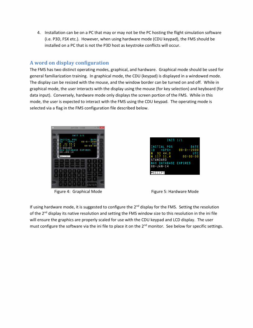
A word on display configuration The FMS has two distinct operating modes, graphical, and hardware. Graphical mode should be used for
general familiarization training. In graphical mode, the CDU (keypad) is displayed in a windowed mode.
The display can be resized with the mouse, and the window border can be turned on and off. While in
graphical mode, the user interacts with the display using the mouse (for key selection) and keyboard (for
data input). Conversely, hardware mode only displays the screen portion of the FMS. While in this
mode, the user is expected to interact with the FMS using the CDU keypad. The operating mode is
selected via a flag in the FMS configuration file described below.
Figure 4: Graphical Mode Figure 5: Hardware Mode
If using hardware mode, it is suggested to configure the 2nd display for the FMS. Setting the resolution
of the 2nd display its native resolution and setting the FMS window size to this resolution in the ini file
will ensure the graphics are properly scaled for use with the CDU keypad and LCD display. The user
must configure the software via the ini file to place it on the 2nd monitor. See below for specific settings.
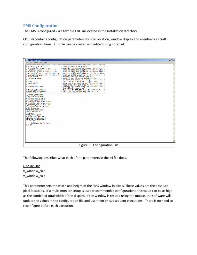
FMS Configuration The FMS is configured via a text file CDU.ini located in the installation directory.
CDU.ini contains configuration parameters for size, location, window display and eventually aircraft
configuration items. This file can be viewed and edited using notepad.
Figure 6: Configuration File
The following describes what each of the parameters in the ini file does.
Display Size
x_window_size
y_window_size
This parameter sets the width and height of the FMS window in pixels. These values are the absolute
pixel locations. If a multi-monitor setup is used (recommended configuration), this value can be as high
as the combined total width of the display. If the window is resized using the mouse, the software will
update the values in the configuration file and use them on subsequent executions. There is no need to
reconfigure before each execution.

Display Position
x_window_position:
y_window_position:
This parameter sets the location of the FMS window on the monitor (in pixels) relative to the upper left
corner of the display. If the window is moved using the mouse, the software will update the values in
the configuration file and use them on subsequent executions. There is no need to reconfigure before
each execution.
Graphics Position
x_graphics_position
y_graphics_position
Default (0) – Set this to 0 to reset to default placement.
This parameter sets the position of the graphics within the window. This parameter can be adjusted
with the software running by using the numberpad arrow keys (2,4,6,8) on the keyboard. Once the
desired position is achieved, the software will record the values in the ini file for future placement.
NOTE: This graphics position can only be adjusted in hardware mode with the Enable_dual_FMS parameter=no It is strongly suggested to adjust each FMS separately to avoid keystroke conflicts during adjustment
Graphics Scale
x_graphic_scale
y_graphic_scale
Default (0) – Set this to 0 to reset to default scale.
This parameter sets the horizontal and vertical scale of the graphics within the window. This parameter
can be adjusted with the software running by using the arrow keys (up, down, left, right) on the
keyboard. This should be used to shrink or stretch the graphics to an LCD which may be partially
obstructed by a bezel. Once the desired position is achieved, the software will record the values in the
ini file for future placement.
NOTE: This graphics scale can only be adjusted in hardware mode with the Enable_dual_FMS parameter set to “no” It is strongly suggested to adjust each FMS separately to avoid keystroke conflicts during adjustment

Window Style
show_frame:yes
Options – yes or no
Setting this value to yes will allow the display of the window along with the standard minimize and close
buttons. Setting this value to no will remove the frame from the window. Note that you cannot resize,
minimize, or close the window using the mouse while in Frameless mode.
Figure 7: Window with Frame Figure 8: Frameless Window
NOTE: This frame option is ignored while in hardware mode, so this does not need to be set to “no” if using hardware LCD/CDU keypad.
Hardware Mode
hardware_mode:no
Options – yes or no
Setting this value to yes will enable hardware mode. In this mode, it is assumed the user will interact
with the FMS software via the CDU keypad. No graphical keypad will be displayed and the screen
graphics will be scaled to fit the x_window_size and y_window_size parameters. Reference figures 2
and 3 for visual examples of hardware vs graphical mode.
Aircraft Configuration Parameters
basic_weight:13500
Options – Aircraft basic weight (lbs)
Basic weight of the aircraft, loaded into the fuel configuration pages. Updating this value in the FMS will
save to the ini file for later recall.

Dual FMS Settings
FMS1:yes
Options – yes or no
This value sets whether the instance of the FMS will be the pilot side (FMS1) or the copilot side (FMS2).
This should be used to setup dual FMS installations.
The hardware key mapping list at the end of this document should be used to configure the keyboard
encoder in use with the CDU keypad in order to ensure the proper keypresses get to the appropriate
FMS. The FMS continually monitors all PC keyboard inputs using a keylogger routine.
No other program or configuration is needed (i.e. Autohotkey)
Dual FMS CrossFill (in development)
FMS1_xfill:push
Options – push or pull
This option enables push or pull from FMS1 to FMS2 (push) or FMS2 to FMS1 (pull) of fuel initialization
data and flight plans in dual installations. This allows a syncing of the two FMSs instead of having to
duplicate initial entries in both FMSs. This feature is currently in development and not 100% functional.
Refer to official UNS-1 training documentation for more detailed information on how this works.
Dual FMS Enable
Enable_dual_FMS:no
Options – yes or no
This option enables the key handling and xfill logic. Only set this value to yes if you have two FMS units
running.
NOTE: Use the key mapping table in the section below to configure the keyboard encoder used for the CDU keypad. Note the key mapping for a single FMS installation is different than a dual FMS installation.
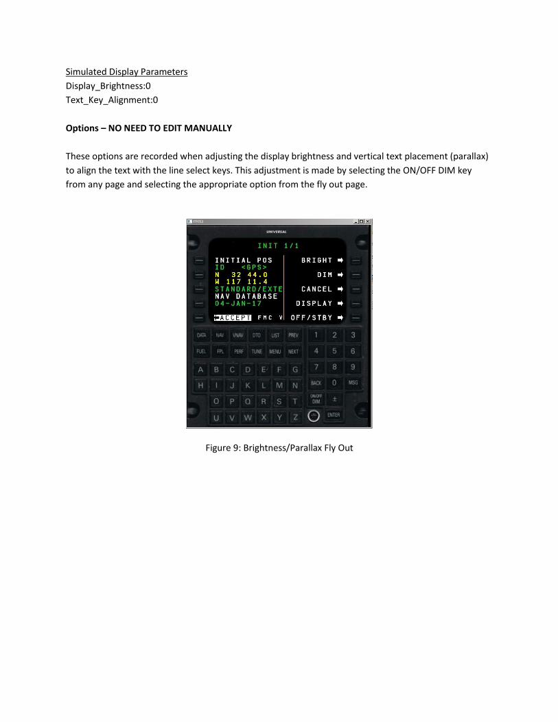
Simulated Display Parameters
Display_Brightness:0
Text_Key_Alignment:0
Options – NO NEED TO EDIT MANUALLY
These options are recorded when adjusting the display brightness and vertical text placement (parallax)
to align the text with the line select keys. This adjustment is made by selecting the ON/OFF DIM key
from any page and selecting the appropriate option from the fly out page.
Figure 9: Brightness/Parallax Fly Out
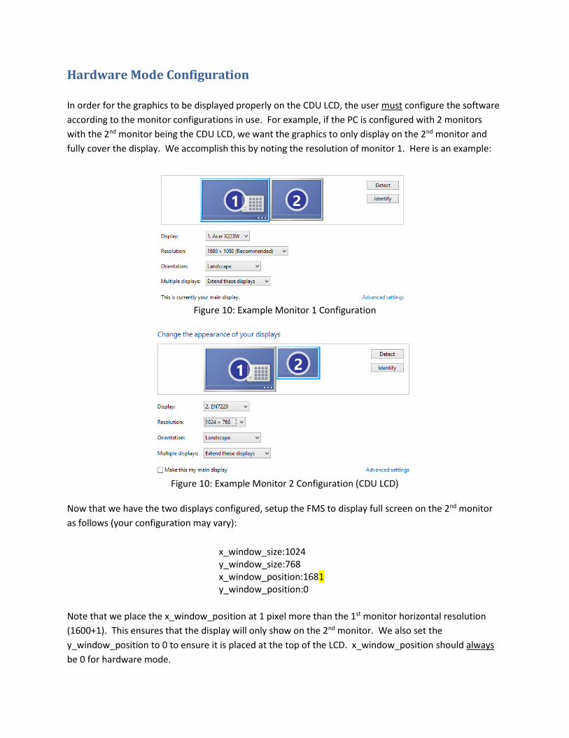
Hardware Mode Configuration
In order for the graphics to be displayed properly on the CDU LCD, the user must configure the software
according to the monitor configurations in use. For example, if the PC is configured with 2 monitors
with the 2nd monitor being the CDU LCD, we want the graphics to only display on the 2nd monitor and
fully cover the display. We accomplish this by noting the resolution of monitor 1. Here is an example:
Figure 10: Example Monitor 1 Configuration
Figure 10: Example Monitor 2 Configuration (CDU LCD)
Now that we have the two displays configured, setup the FMS to display full screen on the 2nd monitor
as follows (your configuration may vary):
x_window_size:1024 y_window_size:768 x_window_position:1681 y_window_position:0
Note that we place the x_window_position at 1 pixel more than the 1st monitor horizontal resolution
(1600+1). This ensures that the display will only show on the 2nd monitor. We also set the
y_window_position to 0 to ensure it is placed at the top of the LCD. x_window_position should always
be 0 for hardware mode.

x_window_size and y_window_size should always match the resolution of the CDU LCD screen, in this
example 1024x768.
We must set hardware_mode to 1 while using the CDU keypad/LCD.
The user can adjust the scale and placement of the text graphics on the CDU LCD screen using the PC
keyboard and numberpad arrows. This can only be done while in hardware mode and single FMS is
configured in the ini file.
Once configured properly, the display will always startup and fill the CDU LCD screen. No further user
inputs or changes should be required.
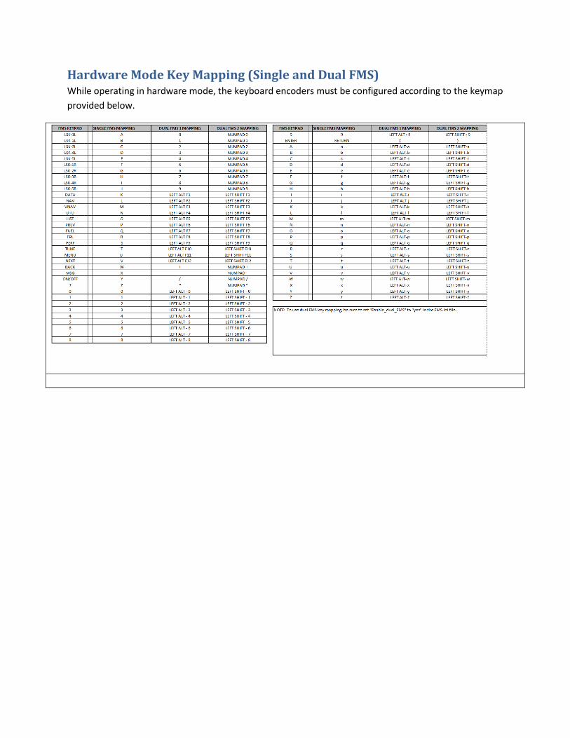
Hardware Mode Key Mapping (Single and Dual FMS) While operating in hardware mode, the keyboard encoders must be configured according to the keymap
provided below.

Notes on aircraft setup (P3D, FSX) In order for the FMS to be able to perform LNAV and VNAV properly, make sure the following two lines
are in the aircraft.cfg file:
use_no_default_bank=1
use_no_default_pitch=1
The FMS does not use the default GPS/FMS autopilot modes within the flight model in FSX/P3D.
Instead, it operates externally by manipulating the control surfaces directly through FSUIPC. If the
above lines are in the configuration file for the aircraft and set to 0, or they are not present at all in the
file, when the autopilot is engaged without a lateral mode active (as will be the case when the FMS is
navigating), the autopilot within the simulator will level the wings or fly north. This will prevent the FMS
from navigating the lateral waypoint plan.