Embed Size (px)
Citation preview
1
FMS interface User_Guide_22062012
2
Related Documents
SAE J1939 / 71 Vehicle Application Layer Clarification of FMS data
SAE J1708
SAE J1587
Notation of special characters
*CR+ Enter key or character code carriage return (0x0D) – if you will use Terminal in macro mode
you must type: $0D
*LF+ character code linefeed (0x0A)
*NULL+ means no character
Version History Edition Date State
22062012 June 2012 5th
edition: 1- Updated for CANGO FMS interface second generation
08022012 February 2012 4th
edition: New configuration protocol
05082011 August 2011 3rd
edition: New features/paragraphs: Start in A0 mode (> Command) T Command S2 Frame Format Updated features/paragraphs F Command (Only view function) Content updates (screenshots, explanations, and examples) throughout the document.
17022011 February 2011 2nd
edition: New features/paragraphs: General Considerations about Configuration Mode GP Command GS Command JF Command JD Command Updated features/paragraphs F Command (F4, F5, F6, F7) Minor content updates (screenshots, explanations, and examples) throughout the document.
10082010 April 2010 1st
edition
3
Table of Contents
Table of Contents........................................................................................................................... 3
1 PRODUCT PHILOSOPHY .......................................................................................................... 5
2 SUPPORTED TRUCKS & EQUIPMENT ...................................................................................... 6
3 HARDWARE DESCRIPTION ...................................................................................................... 7
3.1 Description ...................................................................................................................... 7
3.2 Device communication interface .................................................................................. 11
3.2.1 RS232 interface ........................................................................................................ 11
3.2.2 CAN interface ........................................................................................................... 11
3.2.3 J-Bus interface ......................................................................................................... 11
3.2.4 CANbus + J-Bus configuration ................................................................................. 11
4 INSTALLATION AND GENERAL OVERVIEW ............................................................................ 12
4.1 Power up the CANGO interface .................................................................................... 12
4.2 Installation for FMS output ........................................................................................... 13
4.3 Installation for RS232 output ........................................................................................ 14
4.4 Installation for CAN input with CANGOclick ................................................................. 14
4.5 Installation for CAN input with wire to wire connection .............................................. 15
4.6 Installation for two CAN inputs ..................................................................................... 16
4.7 Installation for J1708 input ........................................................................................... 17
5 FMS Mode ............................................................................................................................ 18
5.1 Serial Output Frames .................................................................................................... 18
5.1.1 Readable frame ....................................................................................................... 18
5.1.2 Spreadsheet frame .................................................................................................. 18
5.1.3 “T” frames ............................................................................................................... 19
5.2 Frames timing................................................................................................................ 19
6 CONFIGURATION MODE ....................................................................................................... 20
6.1 General Considerations about Configuration Mode ..................................................... 20
6.2 Commands overview ..................................................................................................... 20
6.3 Config Mode - #CFG command ..................................................................................... 21
6.4 Enter FMS Mode - #FMS command .............................................................................. 22
6.5 UART baud rate - #sbaud command ............................................................................. 23
6.6 CAN baud rate - #cbaud command ............................................................................... 24
6.7 Serial frame repeat interval - #sint command .............................................................. 25
6.8 Serial frame offset broadcast time ................................................................................ 26
6.9 Mask for output values - #mask command .................................................................. 27
6.10 Setting the field separator character for the spreadsheet and frame format - #spt command .............................................................................................................. 29
6.11 Setting the prefix for the spreadsheet and frame format - #pfx command ................. 30
6.12 Setting the suffix for the spreadsheet and frame format - #sfx command .................. 31

4
6.13 Save configuration - #save command ........................................................................... 32
6.14 Discard configuration - #discard command .................................................................. 32
6.15 Reset - #reset command ............................................................................................... 32
7 LED status ............................................................................................................................. 33
DISCLAIMERS ............................................................................................................................... 34
Life support.............................................................................................................................. 34
Right to make changes ............................................................................................................ 34

5
1 PRODUCT PHILOSOPHY
CANGO FMS interface is a smart platform that can power-up your telematic solution with the
ability to connect to the CANbus, J-Bus or K-Line of most important trucks, cars and equipment.
Because of the flexible hardware design and the options to setup the software, the device can
be used in multiple ways and designed for specific requirements.
The input of CANBUS FMS interface can be:
CANbus part no. 7164-11 or 7164.2CK
CANbus + J-Bus part no. 7164-12
The output of CANbus FMS interface can be:
serial link (RS232) – pure ASCII code, making data handling very easy. You only have to
interpret the ASCII data in the received serial strings following the manual instructions;
CANbus FMS 2.0 standard.
Once you made the configuration through the serial link, the CANGO FMS interface will keep
the pre-programming because all data are stored in the internal nonvolatile memory.
The serial link of the CANGO FMS interface supports baud rates from 9600 up to 115200 bps.

6
2 SUPPORTED TRUCKS & EQUIPMENT
Please contact us for detailed vehicles support list.
7
3 HARDWARE DESCRIPTION
3.1 Description
The CANGO FMS interface uses a physical layer according to ISO 11898-2(250 Kbit/s), an
application layer according to SAE J1939/71 and also a data link layer according to SAE J1939/21 that
provides complete J1939: FMS. Also it could use a physical layer according SAE J2284-1 (125 Kbit/s) or
SAE J2284-3 (500 Kbit/s) and upper layers according to proprietary protocols.
CANGO FMS interface also includes SAE J1708 that defines a serial, bidirectional network to be
used in the commercial vehicle industry. The SAE J1587 Standard regulates the communication and
standardized data exchange between different ECUs based on SAE J1708 networks.
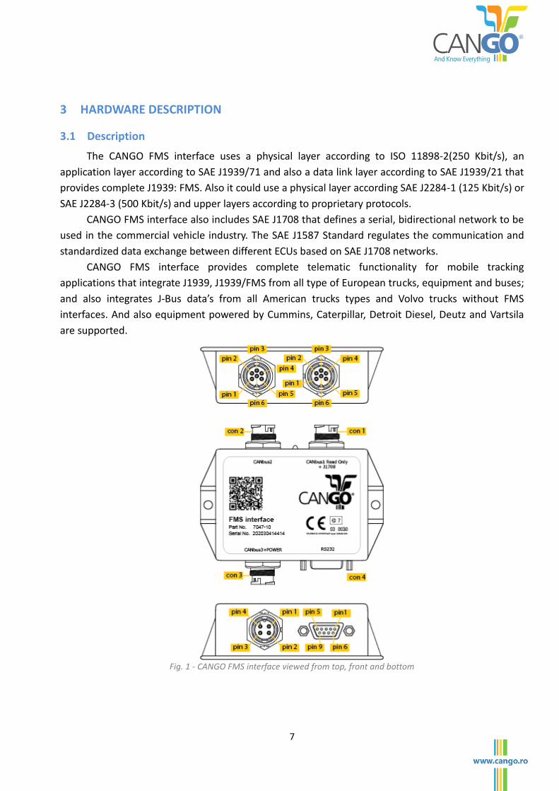
CANGO FMS interface provides complete telematic functionality for mobile tracking
applications that integrate J1939, J1939/FMS from all type of European trucks, equipment and buses;
and also integrates J-Bus data’s from all American trucks types and Volvo trucks without FMS
interfaces. And also equipment powered by Cummins, Caterpillar, Detroit Diesel, Deutz and Vartsila
are supported.
Fig. 1 - CANGO FMS interface viewed from top, front and bottom
8
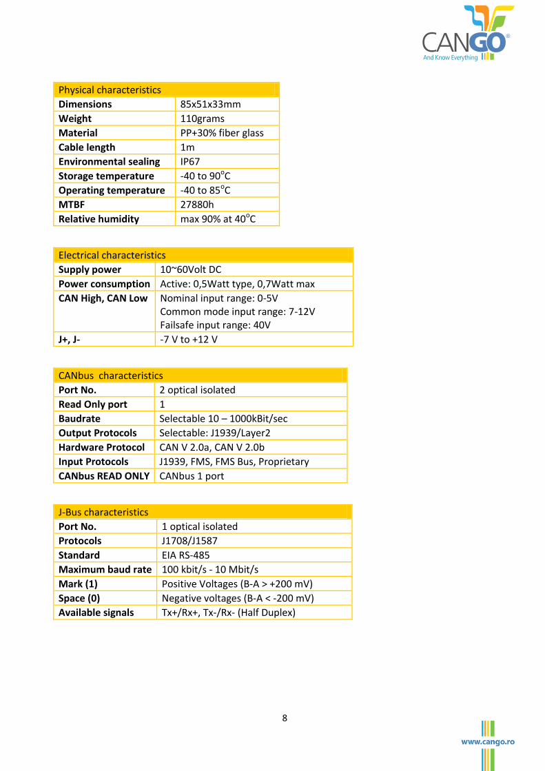
Physical characteristics
Dimensions 85x51x33mm
Weight 110grams
Material PP+30% fiber glass
Cable length 1m
Environmental sealing IP67
Storage temperature -40 to 90oC
Operating temperature -40 to 85oC
MTBF 27880h
Relative humidity max 90% at 40oC
Electrical characteristics
Supply power 10~60Volt DC
Power consumption Active: 0,5Watt type, 0,7Watt max
CAN High, CAN Low Nominal input range: 0-5V Common mode input range: 7-12V Failsafe input range: 40V
J+, J- -7 V to +12 V
CANbus characteristics
Port No. 2 optical isolated
Read Only port 1
Baudrate Selectable 10 – 1000kBit/sec
Output Protocols Selectable: J1939/Layer2
Hardware Protocol CAN V 2.0a, CAN V 2.0b
Input Protocols J1939, FMS, FMS Bus, Proprietary
CANbus READ ONLY CANbus 1 port
J-Bus characteristics
Port No. 1 optical isolated
Protocols J1708/J1587
Standard EIA RS-485
Maximum baud rate 100 kbit/s - 10 Mbit/s
Mark (1) Positive Voltages (B-A > +200 mV)
Space (0) Negative voltages (B-A < -200 mV)
Available signals Tx+/Rx+, Tx-/Rx- (Half Duplex)
9
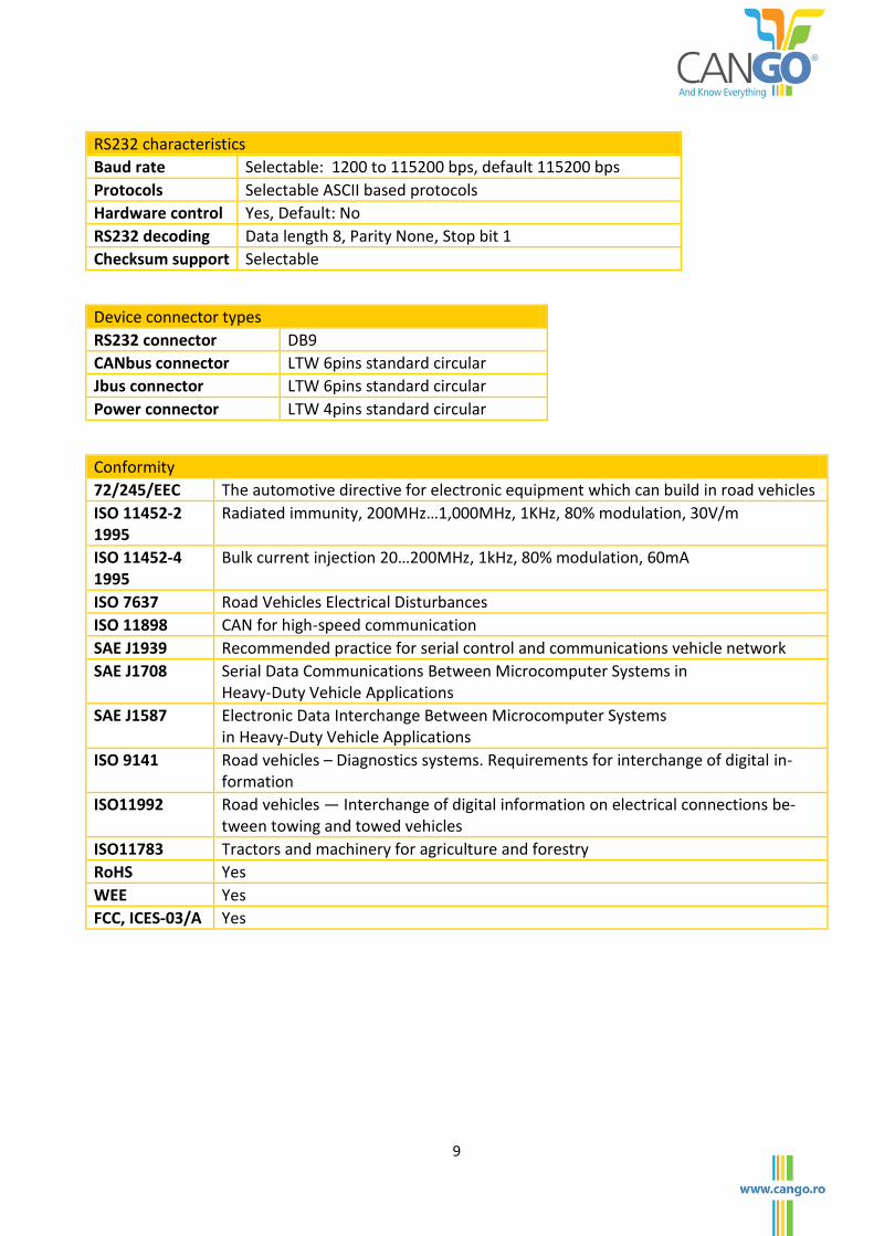
RS232 characteristics
Baud rate Selectable: 1200 to 115200 bps, default 115200 bps
Protocols Selectable ASCII based protocols
Hardware control Yes, Default: No
RS232 decoding Data length 8, Parity None, Stop bit 1
Checksum support Selectable
Device connector types
RS232 connector DB9
CANbus connector LTW 6pins standard circular
Jbus connector LTW 6pins standard circular
Power connector LTW 4pins standard circular
Conformity
72/245/EEC The automotive directive for electronic equipment which can build in road vehicles
ISO 11452-2 1995
Radiated immunity, 200MHz…1,000MHz, 1KHz, 80% modulation, 30V/m
ISO 11452-4 1995
Bulk current injection 20…200MHz, 1kHz, 80% modulation, 60mA
ISO 7637 Road Vehicles Electrical Disturbances
ISO 11898 CAN for high-speed communication
SAE J1939 Recommended practice for serial control and communications vehicle network
SAE J1708 Serial Data Communications Between Microcomputer Systems in Heavy-Duty Vehicle Applications
SAE J1587 Electronic Data Interchange Between Microcomputer Systems in Heavy-Duty Vehicle Applications
ISO 9141 Road vehicles – Diagnostics systems. Requirements for interchange of digital in-formation
ISO11992 Road vehicles — Interchange of digital information on electrical connections be-tween towing and towed vehicles
ISO11783 Tractors and machinery for agriculture and forestry
RoHS Yes
WEE Yes
FCC, ICES-03/A Yes
10
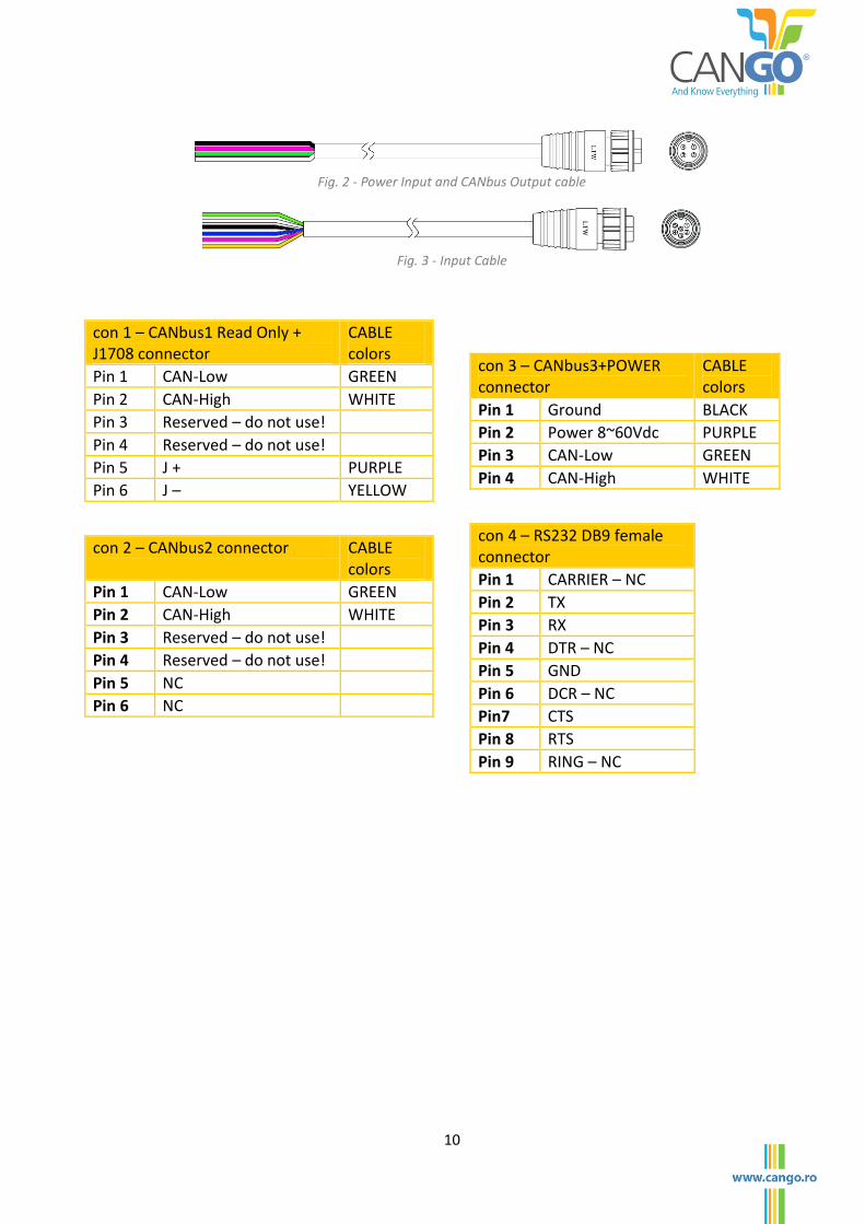
Fig. 2 - Power Input and CANbus Output cable
Fig. 3 - Input Cable
con 1 – CANbus1 Read Only + J1708 connector
CABLE colors
Pin 1 CAN-Low GREEN
Pin 2 CAN-High WHITE
Pin 3 Reserved – do not use!
Pin 4 Reserved – do not use!
Pin 5 J + PURPLE
Pin 6 J – YELLOW
con 2 – CANbus2 connector CABLE colors
Pin 1 CAN-Low GREEN
Pin 2 CAN-High WHITE
Pin 3 Reserved – do not use!
Pin 4 Reserved – do not use!
Pin 5 NC
Pin 6 NC
con 3 – CANbus3+POWER connector
CABLE colors
Pin 1 Ground BLACK
Pin 2 Power 8~60Vdc PURPLE
Pin 3 CAN-Low GREEN
Pin 4 CAN-High WHITE
con 4 – RS232 DB9 female connector
Pin 1 CARRIER – NC
Pin 2 TX
Pin 3 RX
Pin 4 DTR – NC
Pin 5 GND
Pin 6 DCR – NC
Pin7 CTS
Pin 8 RTS
Pin 9 RING – NC
11
3.2 Device communication interface
3.2.1 RS232 interface
CANGO FMS interface includes one RS232 serial interface supporting 8 data bits, 1 stop bit, no
parity and baud rates from 9600 up to 115200 bps. Default baud rate is 115200 bps. Flow control is
supported with RTS/CTS enable, but is disabled by default.
3.2.2 CAN interface
CANGO FMS interfaceincludes 3 CAN v2.0 interfaces. Two of the CAN interfaces, CANbus1 and
CANbus2, are used for input and the CANbus3 sends the output J1939/FMS frames.
All of these CAN interfaces are ISO 11898 compliant.
You can order using part no. 7164-11 for CAN cable, 7164-12 for CAN + J1708 cable, CAN +
power cable or 7164-2CK for CANGOclick ready.
3.2.3 J-Bus interface
CANGO FMS interface device include the J1708/J1587 interface. For this device configuration
use order part no. 7164-12 for CAN + J1708 cable.
3.2.4 CANbus + J-Bus configuration
CANGO FMS interface device can be delivered with both CANbus and J-Bus input. It is used on
vehicles that have both protocols implemented (like Volvo Trucks). For this configuration please use
order part no. 7165.12 (CAN + J1708 cable).
12
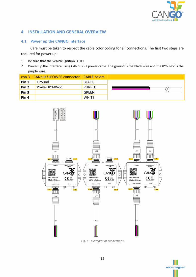
4 INSTALLATION AND GENERAL OVERVIEW
4.1 Power up the CANGO interface
Care must be taken to respect the cable color coding for all connections. The first two steps are
required for power up:
1. Be sure that the vehicle ignition is OFF.
2. Power up the interface using CANbus3 + power cable. The ground is the black wire and the 8~60Vdc is the
purple wire.
con 3 – CANbus3+POWER connector CABLE colors
Pin 1 Ground BLACK
Pin 2 Power 8~60Vdc PURPLE
Pin 3 GREEN
Pin 4 WHITE
Fig. 4 - Examples of connections
13
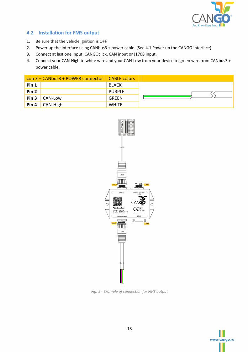
4.2 Installation for FMS output
1. Be sure that the vehicle ignition is OFF.
2. Power up the interface using CANbus3 + power cable. (See 4.1 Power up the CANGO interface)
3. Connect at last one input, CANGOclick, CAN input or J1708 input.
4. Connect your CAN-High to white wire and your CAN-Low from your device to green wire from CANbus3 +
power cable.
con 3 – CANbus3 + POWER connector CABLE colors
Pin 1 BLACK
Pin 2 PURPLE
Pin 3 CAN-Low GREEN
Pin 4 CAN-High WHITE
Fig. 5 - Example of connection for FMS output
14
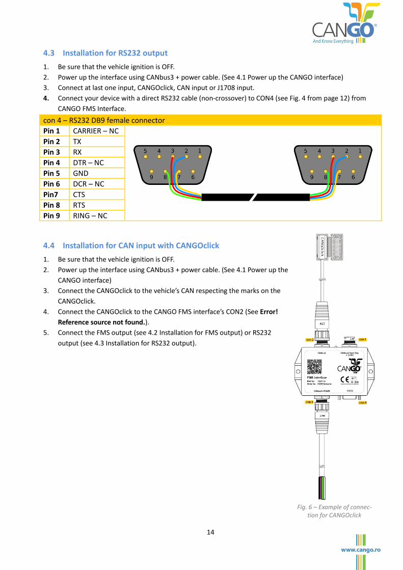
4.3 Installation for RS232 output
1. Be sure that the vehicle ignition is OFF.
2. Power up the interface using CANbus3 + power cable. (See 4.1 Power up the CANGO interface)
3. Connect at last one input, CANGOclick, CAN input or J1708 input.
4. Connect your device with a direct RS232 cable (non-crossover) to CON4 (see Fig. 4 from page 12) from
CANGO FMS Interface.
con 4 – RS232 DB9 female connector
Pin 1 CARRIER – NC
Pin 2 TX
Pin 3 RX
Pin 4 DTR – NC
Pin 5 GND
Pin 6 DCR – NC
Pin7 CTS
Pin 8 RTS
Pin 9 RING – NC
4.4 Installation for CAN input with CANGOclick
1. Be sure that the vehicle ignition is OFF.
2. Power up the interface using CANbus3 + power cable. (See 4.1 Power up the
CANGO interface)
3. Connect the CANGOclick to the vehicle’s CAN respecting the marks on the
CANGOclick.
4. Connect the CANGOclick to the CANGO FMS interface’s CON2 (See Error!
Reference source not found.).
5. Connect the FMS output (see 4.2 Installation for FMS output) or RS232
output (see 4.3 Installation for RS232 output).
Fig. 6 – Example of connec-tion for CANGOclick
15
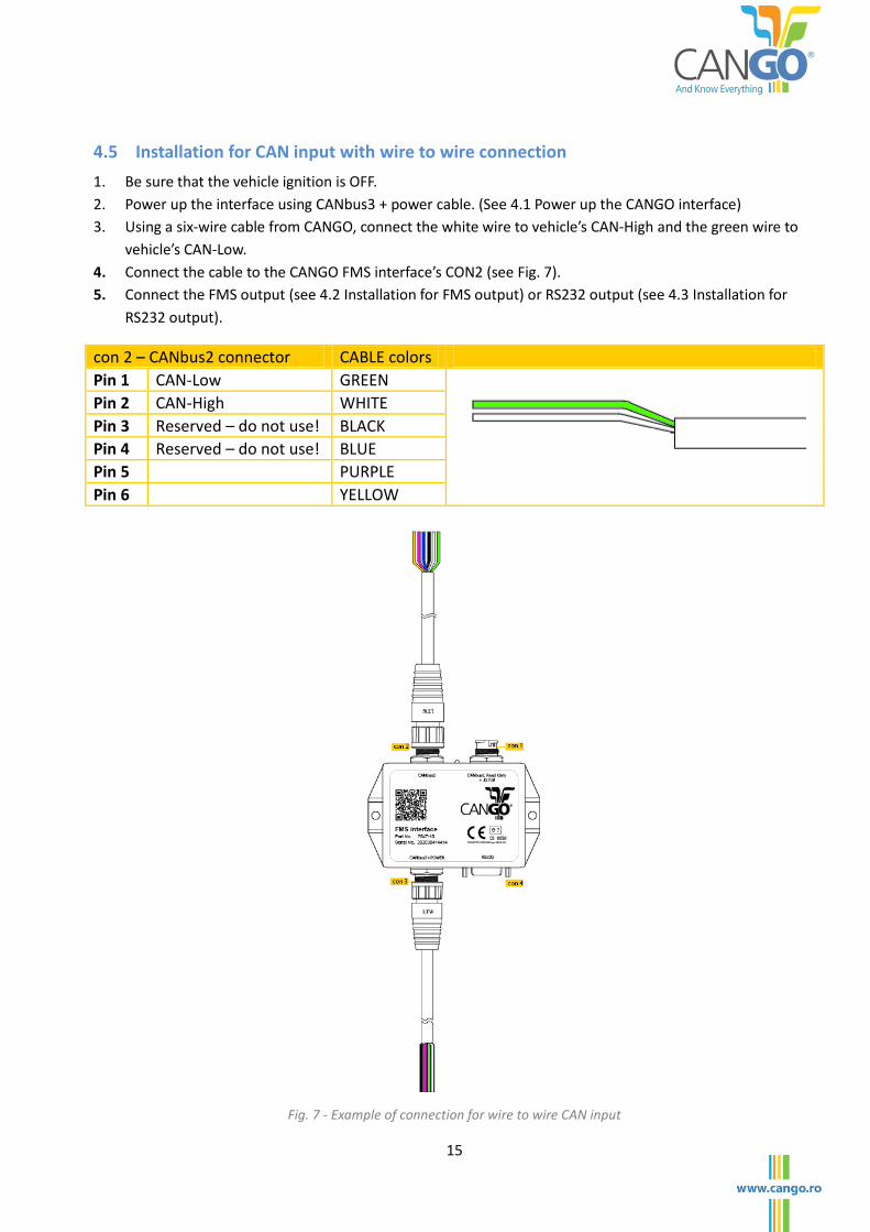
4.5 Installation for CAN input with wire to wire connection
1. Be sure that the vehicle ignition is OFF.
2. Power up the interface using CANbus3 + power cable. (See 4.1 Power up the CANGO interface)
3. Using a six-wire cable from CANGO, connect the white wire to vehicle’s CAN-High and the green wire to
vehicle’s CAN-Low.
4. Connect the cable to the CANGO FMS interface’s CON2 (see Fig. 7).
5. Connect the FMS output (see 4.2 Installation for FMS output) or RS232 output (see 4.3 Installation for
RS232 output).
con 2 – CANbus2 connector CABLE colors
Pin 1 CAN-Low GREEN
Pin 2 CAN-High WHITE
Pin 3 Reserved – do not use! BLACK
Pin 4 Reserved – do not use! BLUE
Pin 5 PURPLE
Pin 6 YELLOW
Fig. 7 - Example of connection for wire to wire CAN input
16
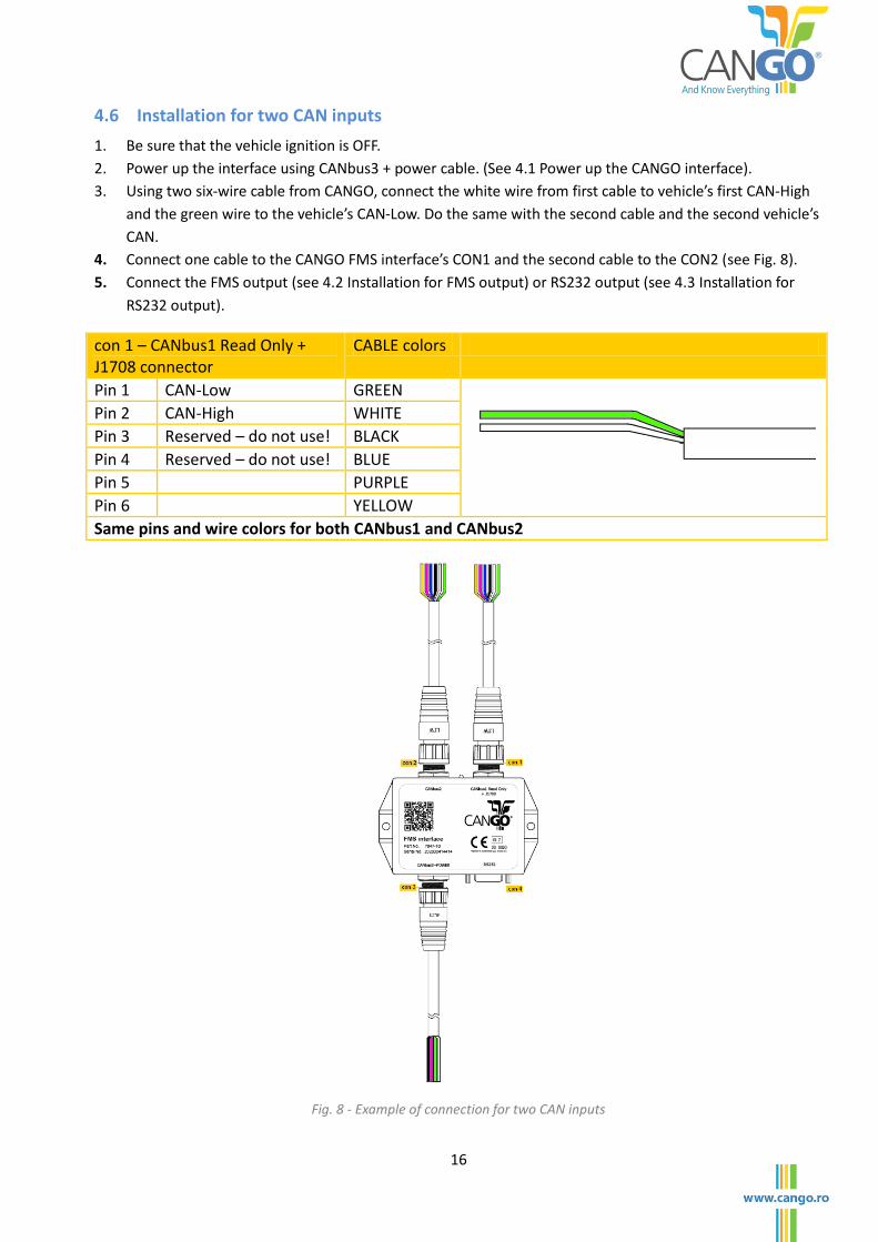
4.6 Installation for two CAN inputs
1. Be sure that the vehicle ignition is OFF.
2. Power up the interface using CANbus3 + power cable. (See 4.1 Power up the CANGO interface).
3. Using two six-wire cable from CANGO, connect the white wire from first cable to vehicle’s first CAN-High
and the green wire to the vehicle’s CAN-Low. Do the same with the second cable and the second vehicle’s
CAN.
4. Connect one cable to the CANGO FMS interface’s CON1 and the second cable to the CON2 (see Fig. 8).
5. Connect the FMS output (see 4.2 Installation for FMS output) or RS232 output (see 4.3 Installation for
RS232 output).
con 1 – CANbus1 Read Only + J1708 connector
CABLE colors
Pin 1 CAN-Low GREEN
Pin 2 CAN-High WHITE
Pin 3 Reserved – do not use! BLACK
Pin 4 Reserved – do not use! BLUE
Pin 5 PURPLE
Pin 6 YELLOW
Same pins and wire colors for both CANbus1 and CANbus2
Fig. 8 - Example of connection for two CAN inputs
17
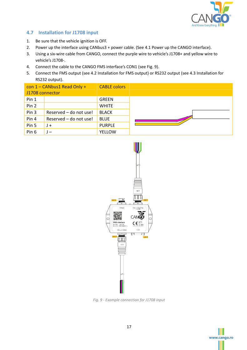
4.7 Installation for J1708 input
1. Be sure that the vehicle ignition is OFF.
2. Power up the interface using CANbus3 + power cable. (See 4.1 Power up the CANGO interface).
3. Using a six-wire cable from CANGO, connect the purple wire to vehicle’s J1708+ and yellow wire to
vehicle’s J1708-.
4. Connect the cable to the CANGO FMS interface’s CON1 (see Fig. 9).
5. Connect the FMS output (see 4.2 Installation for FMS output) or RS232 output (see 4.3 Installation for
RS232 output).
con 1 – CANbus1 Read Only + J1708 connector
CABLE colors
Pin 1 GREEN
Pin 2 WHITE
Pin 3 Reserved – do not use! BLACK
Pin 4 Reserved – do not use! BLUE
Pin 5 J + PURPLE
Pin 6 J – YELLOW
Fig. 9 - Example connection for J1708 input
18
5 FMS Mode
In normal operating mode the interface reads the vehicle data and sends the data to RS232 and
CANbus outputs. Both outputs, RS232 and CANbus, are active.
The ASCII output for the serial link is built up and sent either in a cycle period given by the #sint
command
The serial output is given in the format defined by the #sint parameters, #mask parameter. For
the complete Serial guide please refer to CANGO Serial User Guide.
The data is also being sent like J1939/FMS frames protocol on the CANbus3 port.
5.1 Serial Output Frames
The serial output has three main types of frames. One readable frame, easy to read by human
operator, one spreadsheet frame, and three “T” frames, for instant values, for total values and for
tachograph.
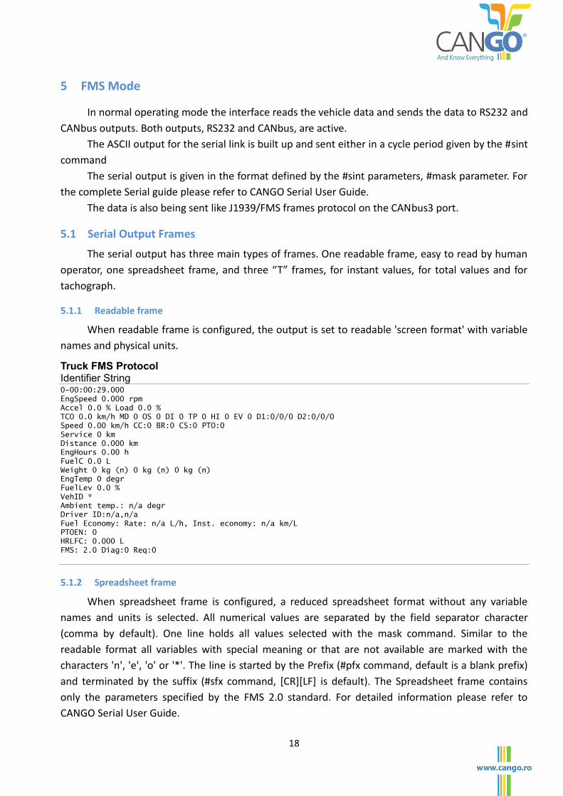
5.1.1 Readable frame
When readable frame is configured, the output is set to readable 'screen format' with variable
names and physical units.
Truck FMS Protocol Identifier String 0-00:00:29.000
EngSpeed 0.000 rpm
Accel 0.0 % Load 0.0 %
TCO 0.0 km/h MD 0 OS 0 DI 0 TP 0 HI 0 EV 0 D1:0/0/0 D2:0/0/0
Speed 0.00 km/h CC:0 BR:0 CS:0 PTO:0
Service 0 km
Distance 0.000 km
EngHours 0.00 h
FuelC 0.0 L
Weight 0 kg (n) 0 kg (n) 0 kg (n)
EngTemp 0 degr
FuelLev 0.0 %
VehID *
Ambient temp.: n/a degr
Driver ID:n/a,n/a
Fuel Economy: Rate: n/a L/h, Inst. economy: n/a km/L
PTOEN: 0
HRLFC: 0.000 L
FMS: 2.0 Diag:0 Req:0
5.1.2 Spreadsheet frame
When spreadsheet frame is configured, a reduced spreadsheet format without any variable
names and units is selected. All numerical values are separated by the field separator character
(comma by default). One line holds all values selected with the mask command. Similar to the
readable format all variables with special meaning or that are not available are marked with the
characters 'n', 'e', 'o' or '*'. The line is started by the Prefix (#pfx command, default is a blank prefix)
and terminated by the suffix (#sfx command, *CR+*LF+ is default). The Spreadsheet frame contains
only the parameters specified by the FMS 2.0 standard. For detailed information please refer to
CANGO Serial User Guide.
19
5.1.3 “T” frames
When “T” frames are configured, the output data is organized on multiple serial frames. Those
frames also contains some additional calculated values (like threshold time for rpm and speed, idle
time) besides the FMS 2.0 standard. For detailed information please refer to CANGO Serial User
Guide.
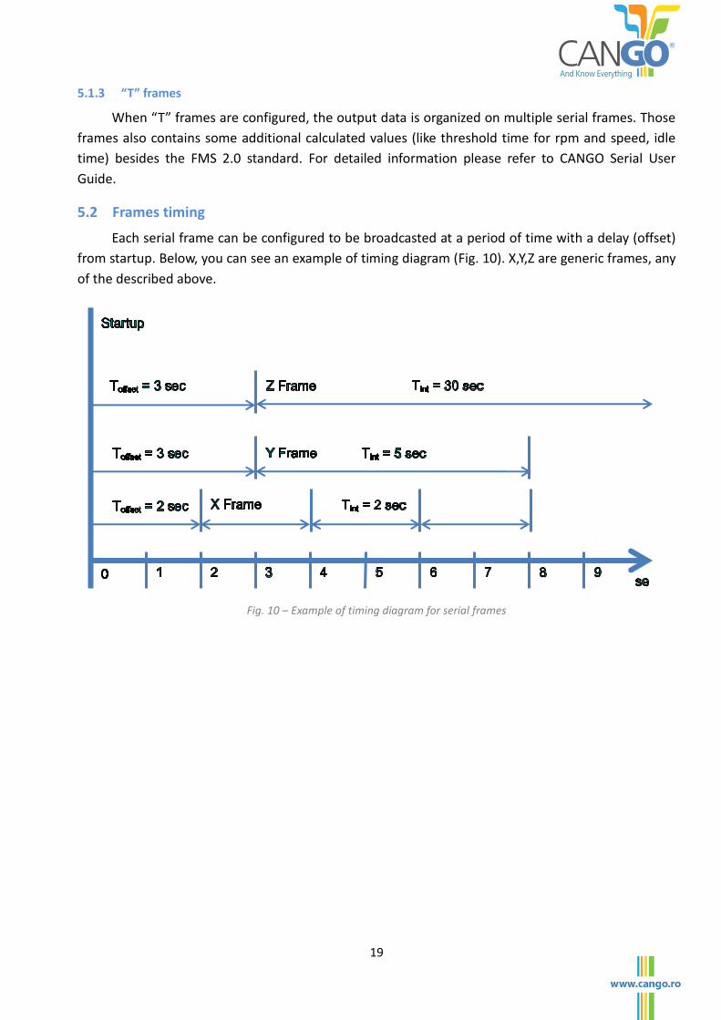
5.2 Frames timing
Each serial frame can be configured to be broadcasted at a period of time with a delay (offset)
from startup. Below, you can see an example of timing diagram (Fig. 10). X,Y,Z are generic frames, any
of the described above.
Fig. 10 – Example of timing diagram for serial frames
20
6 CONFIGURATION MODE
6.1 General Considerations about Configuration Mode
In order to configure CANGO Telematic Interface, the user should use the commands described
below and border them with #CFG Command at the beginning and #reset Command at the end.
Command Description #CFG[CR][LF] Enter Config Mode and get current configuration #command_1[CR][LF] First command #command_2[CR][LF] Second command #command_n[CR][LF] n’th command #CFG[CR][LF] Verify the actual configuration #save[CR][LF] #discard[CR][LF] Save or discard your configuration #reset[CR][LF] #FMS[CR][LF] Reset the interface if you saved your configuration
or return to FMS mode. Table 1 - Example of commands
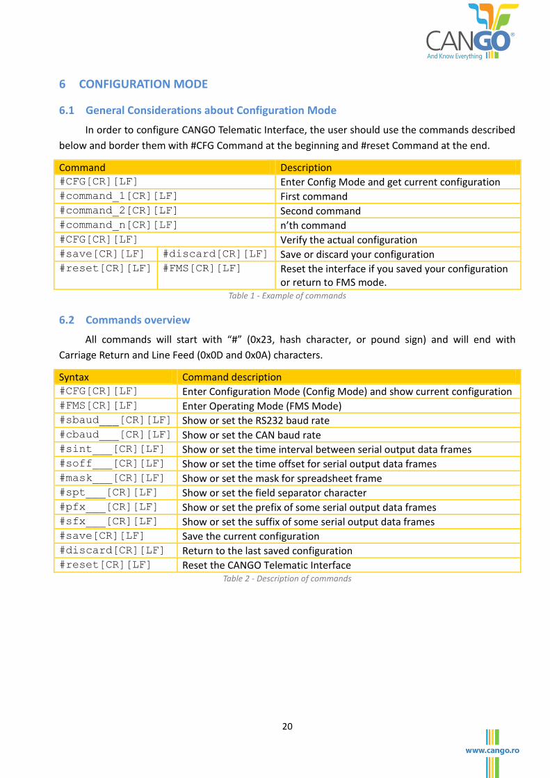
6.2 Commands overview
All commands will start with “#” (0x23, hash character, or pound sign) and will end with
Carriage Return and Line Feed (0x0D and 0x0A) characters.
Syntax Command description #CFG[CR][LF] Enter Configuration Mode (Config Mode) and show current configuration #FMS[CR][LF] Enter Operating Mode (FMS Mode) #sbaud___[CR][LF] Show or set the RS232 baud rate #cbaud___[CR][LF] Show or set the CAN baud rate #sint___[CR][LF] Show or set the time interval between serial output data frames #soff___[CR][LF] Show or set the time offset for serial output data frames #mask___[CR][LF] Show or set the mask for spreadsheet frame #spt___[CR][LF] Show or set the field separator character #pfx___[CR][LF] Show or set the prefix of some serial output data frames #sfx___[CR][LF] Show or set the suffix of some serial output data frames #save[CR][LF] Save the current configuration #discard[CR][LF] Return to the last saved configuration #reset[CR][LF] Reset the CANGO Telematic Interface
Table 2 - Description of commands
21
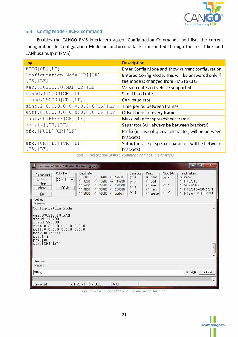
6.3 Config Mode - #CFG command
Enables the CANGO FMS interfaceto accept Configuration Commands, and lists the current
configuration. In Configuration Mode no protocol data is transmitted through the serial link and
CANbus3 output (FMS).
Log Description #CFG[CR][LF] Enter Config Mode and show current configuration Configuration Mode[CR][LF]
[CR][LF]
Entered Config Mode. This will be answered only if the mode is changed from FMS to CFG
ver,030212,F0,MAN[CR][LF] Version date and vehicle supported sbaud,115200[CR][LF] Serial baud rate cbaud,250000[CR][LF] CAN baud rate sint,2,0,0,0,0,0,0,0,0,0[CR][LF] Time period between frames soff,0,0,0,0,0,0,0,0,0,0[CR][LF] Offset time for every frame mask,001FFFFF[CR][LF] Mask value for spreadsheet frame spt,[,][CR][LF] Separator (will always be between brackets) pfx,[NULL][CR][LF] Prefix (in case of special character, will be between
brackets) sfx,[CR][LF][CR][LF]
[CR][LF]
Suffix (in case of special character, will be between brackets)
Table 3 - Description of #CFG command and possible answers
Fig. 11 – Example of #CFG command, using Terminal
22
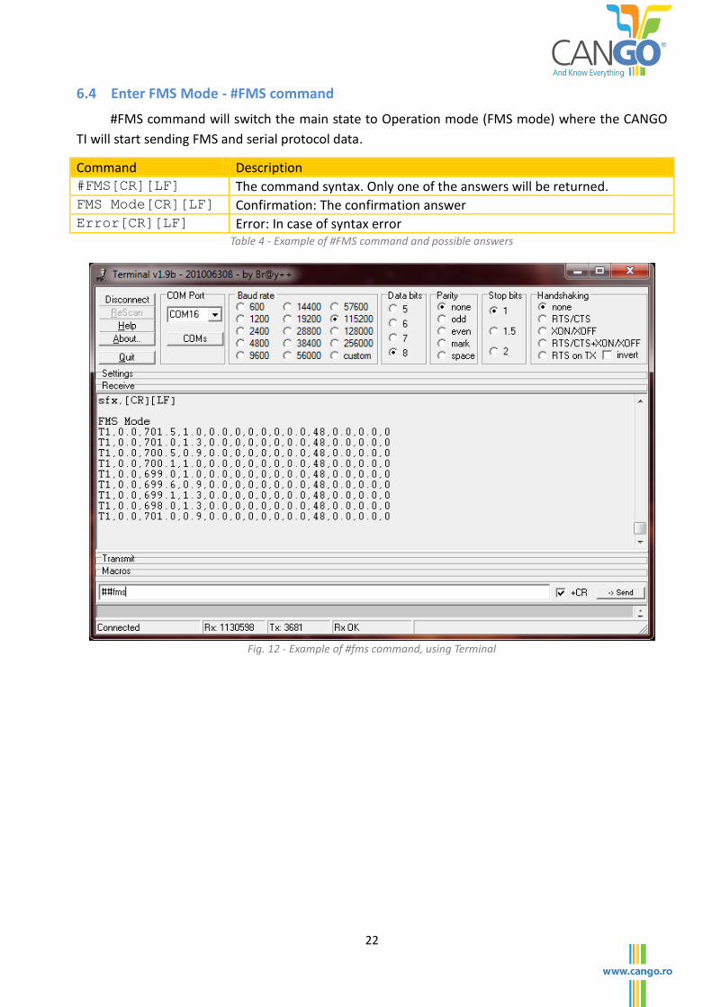
6.4 Enter FMS Mode - #FMS command
#FMS command will switch the main state to Operation mode (FMS mode) where the CANGO
TI will start sending FMS and serial protocol data.
Command Description #FMS[CR][LF] The command syntax. Only one of the answers will be returned. FMS Mode[CR][LF] Confirmation: The confirmation answer Error[CR][LF] Error: In case of syntax error
Table 4 - Example of #FMS command and possible answers
Fig. 12 - Example of #fms command, using Terminal
23
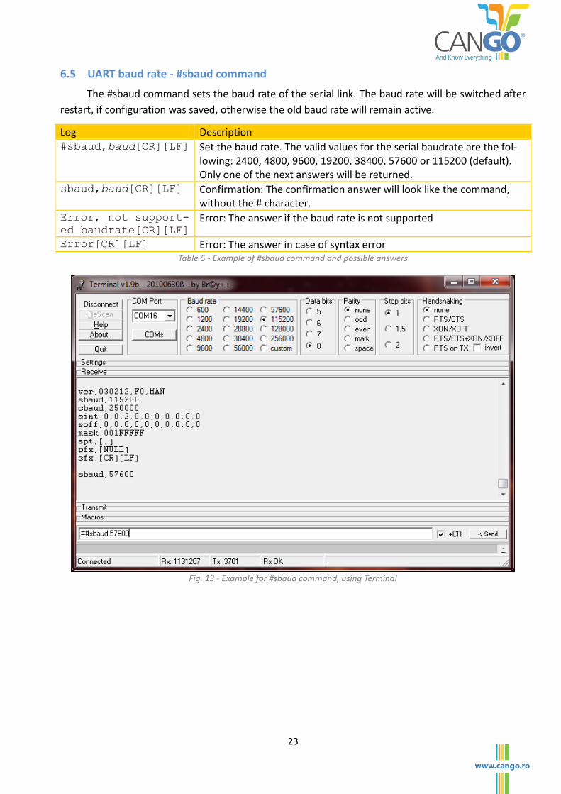
6.5 UART baud rate - #sbaud command
The #sbaud command sets the baud rate of the serial link. The baud rate will be switched after
restart, if configuration was saved, otherwise the old baud rate will remain active.
Log Description #sbaud,baud[CR][LF] Set the baud rate. The valid values for the serial baudrate are the fol-
lowing: 2400, 4800, 9600, 19200, 38400, 57600 or 115200 (default). Only one of the next answers will be returned.
sbaud,baud[CR][LF] Confirmation: The confirmation answer will look like the command, without the # character.
Error, not support-
ed baudrate[CR][LF]
Error: The answer if the baud rate is not supported
Error[CR][LF] Error: The answer in case of syntax error Table 5 - Example of #sbaud command and possible answers
Fig. 13 - Example for #sbaud command, using Terminal
24
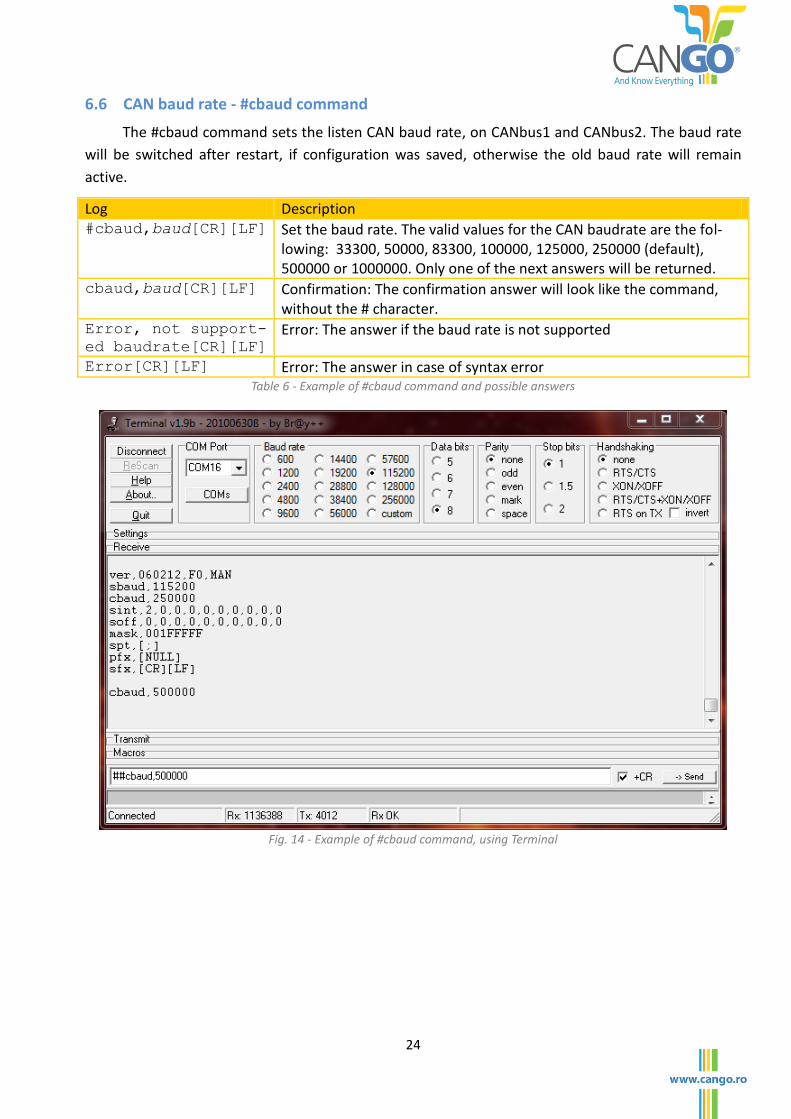
6.6 CAN baud rate - #cbaud command
The #cbaud command sets the listen CAN baud rate, on CANbus1 and CANbus2. The baud rate
will be switched after restart, if configuration was saved, otherwise the old baud rate will remain
active.
Log Description #cbaud,baud[CR][LF] Set the baud rate. The valid values for the CAN baudrate are the fol-
lowing: 33300, 50000, 83300, 100000, 125000, 250000 (default), 500000 or 1000000. Only one of the next answers will be returned.
cbaud,baud[CR][LF] Confirmation: The confirmation answer will look like the command, without the # character.
Error, not support-
ed baudrate[CR][LF]
Error: The answer if the baud rate is not supported
Error[CR][LF] Error: The answer in case of syntax error Table 6 - Example of #cbaud command and possible answers
Fig. 14 - Example of #cbaud command, using Terminal
25
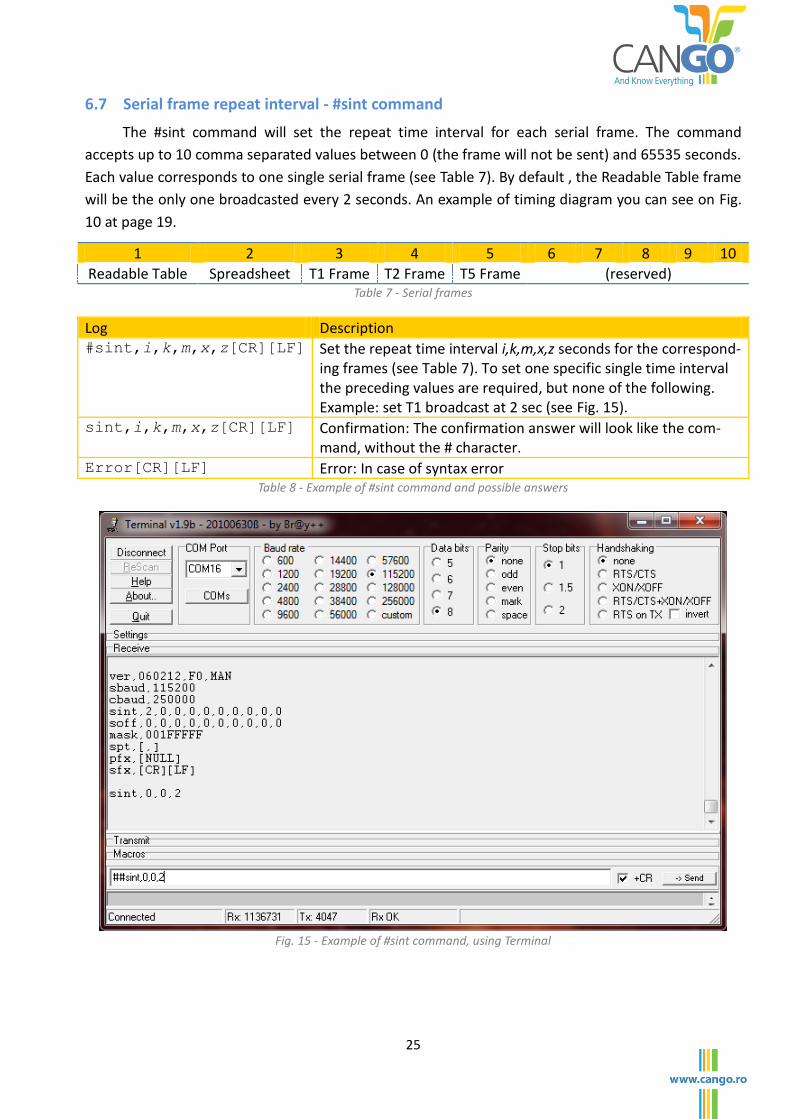
6.7 Serial frame repeat interval - #sint command
The #sint command will set the repeat time interval for each serial frame. The command
accepts up to 10 comma separated values between 0 (the frame will not be sent) and 65535 seconds.
Each value corresponds to one single serial frame (see Table 7). By default , the Readable Table frame
will be the only one broadcasted every 2 seconds. An example of timing diagram you can see on Fig.
10 at page 19.
1 2 3 4 5 6 7 8 9 10
Readable Table Spreadsheet T1 Frame T2 Frame T5 Frame (reserved) Table 7 - Serial frames
Log Description #sint,i,k,m,x,z[CR][LF] Set the repeat time interval i,k,m,x,z seconds for the correspond-
ing frames (see Table 7). To set one specific single time interval the preceding values are required, but none of the following. Example: set T1 broadcast at 2 sec (see Fig. 15).
sint,i,k,m,x,z[CR][LF] Confirmation: The confirmation answer will look like the com-mand, without the # character.
Error[CR][LF] Error: In case of syntax error Table 8 - Example of #sint command and possible answers
Fig. 15 - Example of #sint command, using Terminal
26
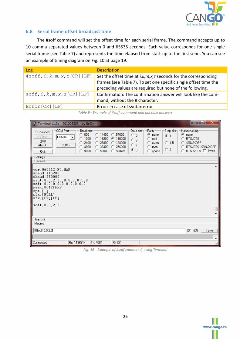
6.8 Serial frame offset broadcast time
The #soff command will set the offset time for each serial frame. The command accepts up to
10 comma separated values between 0 and 65535 seconds. Each value corresponds for one single
serial frame (see Table 7) and represents the time elapsed from start-up to the first send. You can see
an example of timing diagram on Fig. 10 at page 19.
Log Description #soff,i,k,m,x,z[CR][LF] Set the offset time at i,k,m,x,z seconds for the corresponding
frames (see Table 7). To set one specific single offset time the preceding values are required but none of the following.
soff,i,k,m,x,z[CR][LF] Confirmation: The confirmation answer will look like the com-mand, without the # character.
Error[CR][LF] Error: In case of syntax error Table 9 - Example of #soff command and possible answers
Fig. 16 - Example of #soff command, using Terminal
27
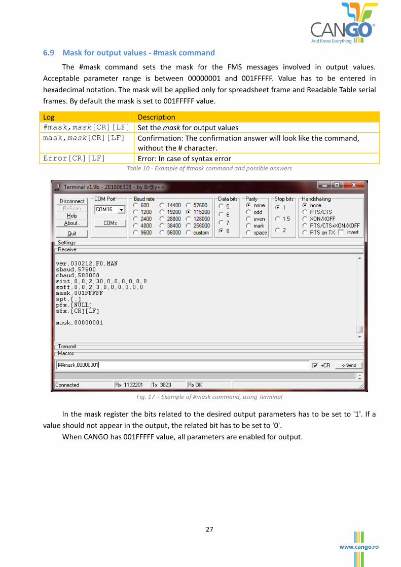
6.9 Mask for output values - #mask command
The #mask command sets the mask for the FMS messages involved in output values.
Acceptable parameter range is between 00000001 and 001FFFFF. Value has to be entered in
hexadecimal notation. The mask will be applied only for spreadsheet frame and Readable Table serial
frames. By default the mask is set to 001FFFFF value.
Log Description #mask,mask[CR][LF] Set the mask for output values mask,mask[CR][LF] Confirmation: The confirmation answer will look like the command,
without the # character. Error[CR][LF] Error: In case of syntax error
Table 10 - Example of #mask command and possible answers
Fig. 17 – Example of #mask command, using Terminal
In the mask register the bits related to the desired output parameters has to be set to '1'. If a
value should not appear in the output, the related bit has to be set to '0'.
When CANGO has 001FFFFF value, all parameters are enabled for output.
28
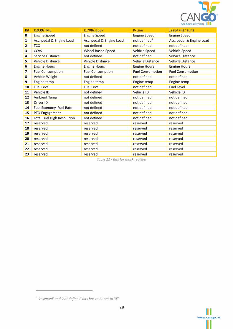
Bit J1939/FMS J1708/J1587 K-Line J2284 (Renault)
0 Engine Speed Engine Speed Engine Speed Engine Speed
1 Acc. pedal & Engine Load Acc. pedal & Engine Load not defined1 Acc. pedal & Engine Load
2 TCO not defined not defined not defined
3 CCVS Wheel Based Speed Vehicle Speed Vehicle Speed
4 Service Distance not defined not defined Service Distance
5 Vehicle Distance Vehicle Distance Vehicle Distance Vehicle Distance
6 Engine Hours Engine Hours Engine Hours Engine Hours
7 Fuel Consumption Fuel Consumption Fuel Consumption Fuel Consumption
8 Vehicle Weight not defined not defined not defined
9 Engine temp Engine temp Engine temp Engine temp
10 Fuel Level Fuel Level not defined Fuel Level
11 Vehicle ID not defined Vehicle ID Vehicle ID
12 Ambient Temp not defined not defined not defined
13 Driver ID not defined not defined not defined
14 Fuel Economy, Fuel Rate not defined not defined not defined
15 PTO Engagement not defined not defined not defined
16 Total Fuel High Resolution not defined not defined not defined
17 reserved reserved reserved reserved
18 reserved reserved reserved reserved
19 reserved reserved reserved reserved
20 reserved reserved reserved reserved
21 reserved reserved reserved reserved
22 reserved reserved reserved reserved
23 reserved reserved reserved reserved
Table 11 - Bits for mask register
1 ‘reserved' and 'not defined' bits has to be set to '0'’
29
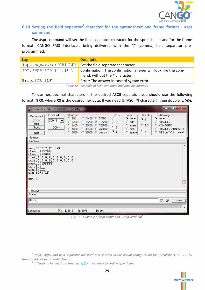
6.10 Setting the field separator2 character for the spreadsheet and frame format - #spt command
The #spt command will set the field separator character for the spreadsheet and for the frame
format. CANGO FMS interfaceis being delivered with the “,” (comma) field separator pre-
programmed.
Log Description #spt,separator[CR][LF] Set the field separator character spt,separator[CR][LF] Confirmation: The confirmation answer will look like the com-
mand, without the # character. Error[CR][LF] Error: The answer in case of syntax error
Table 12 - Example of #spt command and possible answers
To use hexadecimal characters in the desired ASCII separator, you should use the following
format: %XX, where XX is the desired hex byte. If you need % (ASCII % character), then double it: %%.
Fig. 18 - Example of #spt command, using Terminal
3
2 Prefix, suffix and field separator are used and showed in the actual configuration for spreadsheet, T1, T2, T5
frames and not for readable frame. 3 In Terminal for special characters #, $, < , you have to double type them.
30
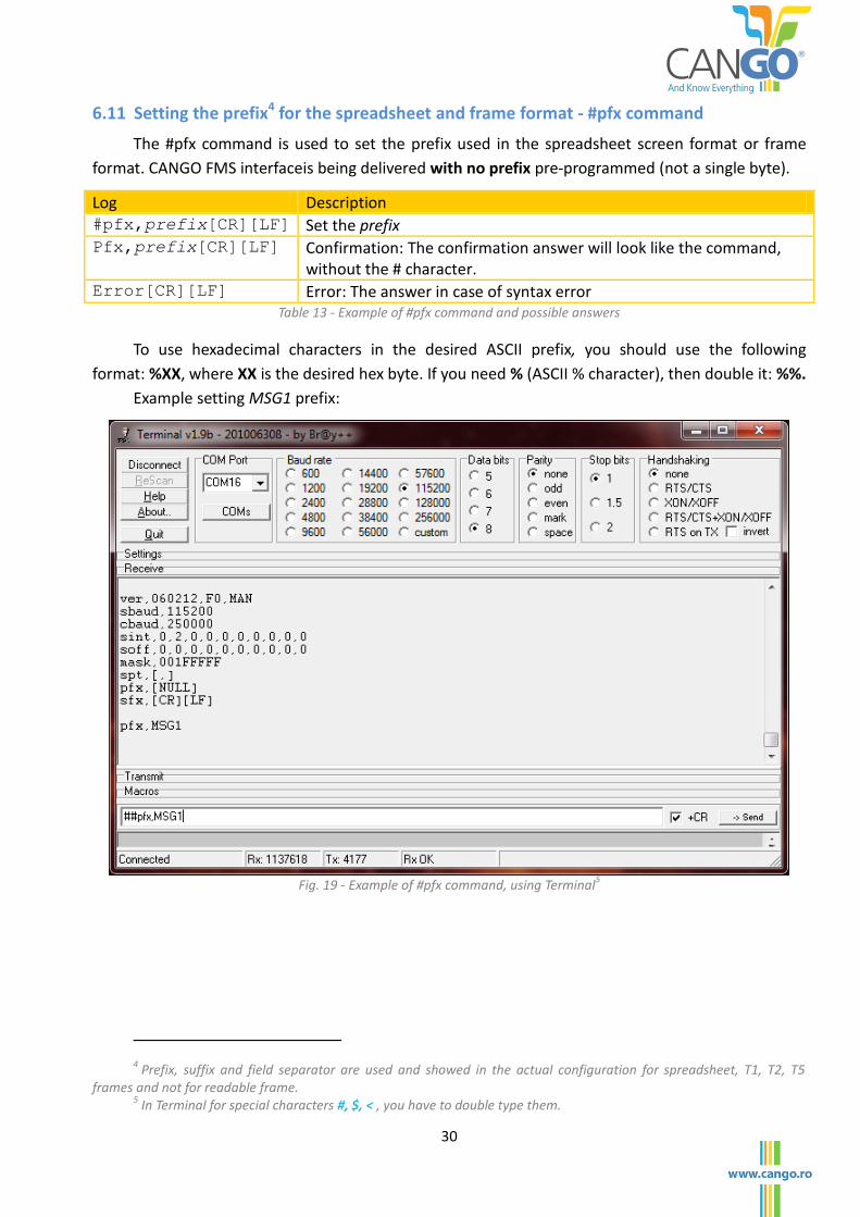
6.11 Setting the prefix4 for the spreadsheet and frame format - #pfx command
The #pfx command is used to set the prefix used in the spreadsheet screen format or frame
format. CANGO FMS interfaceis being delivered with no prefix pre-programmed (not a single byte).
Log Description #pfx,prefix[CR][LF] Set the prefix Pfx,prefix[CR][LF] Confirmation: The confirmation answer will look like the command,
without the # character. Error[CR][LF] Error: The answer in case of syntax error
Table 13 - Example of #pfx command and possible answers
To use hexadecimal characters in the desired ASCII prefix, you should use the following
format: %XX, where XX is the desired hex byte. If you need % (ASCII % character), then double it: %%.
Example setting MSG1 prefix:
Fig. 19 - Example of #pfx command, using Terminal
5
4 Prefix, suffix and field separator are used and showed in the actual configuration for spreadsheet, T1, T2, T5
frames and not for readable frame. 5 In Terminal for special characters #, $, < , you have to double type them.

31
6.12 Setting the suffix6 for the spreadsheet and frame format - #sfx command
The #sfx command sets in the suffix used in the spreadsheet format or frame format. CANGO
FMS interfaceis being delivered with the [CR][LF] suffix pre-programmed
Log Description #sfx,suffix[CR][LF] Set the suffix. sfx,suffix[CR][LF] Confirmation: The confirmation answer will look like the command,
without the # character. Error[CR][LF] Error: The answer in case of syntax error
Table 14 - Example of #sfx command and possible answers
To use hexadecimal characters in the desired ASCII suffix, you should use the following
format: %XX, where XX is the desired hex byte. If you need % (ASCII % character), then double it: %%.
Example setting end[CR][LF] suffix:
Fig. 20 - Example of #sfx command, using Terminal
7
6 Prefix, suffix and field separator are used and showed in the actual configuration for spreadsheet, T1, T2, T5
frames and not for readable frame. 7 In Terminal for special characters #, $, < , you have to double type them.

32
6.13 Save configuration - #save command
The #save command will save the current configuration to permanent memory, to be held after
reset. All changed settings will be lost if Save Command is not used before reset.
Log Description #save[CR][LF] Will save the current configuration in permanent
memory Configuration saved, reset
to apply [CR][LF]
Confirmation: The confirmation answer
Error[CR][LF] Error: In case of syntax error Table 15 - Example of #save command and possible answers
6.14 Discard configuration - #discard command
The #discard command will revert actual configuration to the last saved state. This command is
useful when you made a mistake in your configuration and want to revert.
Log Description #discard[CR][LF] The configuration was reverted to the last saved state. Configuration discard-
ed[CR][LF]
Confirmation: The confirmation answer
Error[CR][LF] Error: In case of syntax error Table 16 - Example of #discard command and possible commands
6.15 Reset - #reset command
The #reset command will reset the CANGO Telematic Interface. At startup the configuration will
be loaded from permanent memory. Use this command to apply the settings before save.
Example of the command
Log Description #reset[CR][LF] The device will be reset booting...[CR][LF] Confirmation: The confirmation answer. Means that the device was re-
started and now it is in startup Error[CR][LF] Error: In case of syntax error
Table 17 - Example of #reset command and possible answers
33
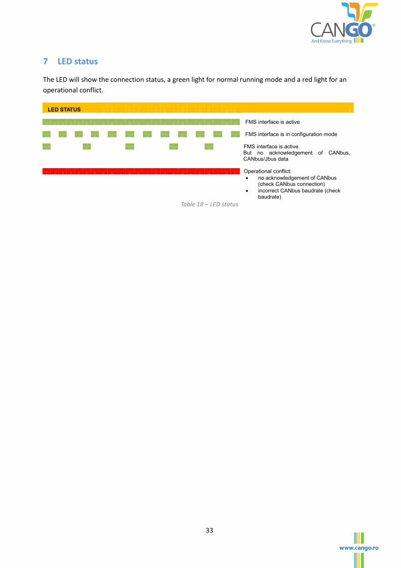
7 LED status
The LED will show the connection status, a green light for normal running mode and a red light for an
operational conflict.
LED STATUS
FMS interface is active
FMS interface is in configuration mode
FMS interface is active.
But no acknowledgement of CANbus, CANbus/Jbus data
Operational conflict:
no acknowledgement of CANbus (check CANbus connection)
incorrect CANbus baudrate (check baudrate)
Table 18 – LED status

34
DISCLAIMERS
Life support
Products are not designed for use in life support appliances, devices or systems where
malfunction of these products can reasonably be expected to result in personal injury.
Gotrack Technology s.r.l. customers using or selling these products for use in such applications
do so at their own risk and agree to fully indemnify Gotrack Technology s.r.l. for any damages
resulting from such application.
Right to make changes
Gotrack Technology s.r.l. reserves the right to make changes, without notice, in the products,
and/or software, described or contained herein in order to improve design and/or performance.
Gotrack Technology s.r.l. assumes no responsibility or liability for use of any of these products,
conveys no license or title under any patent, copyright, or masks work to right to these products, and
makes no representations or warranties that these products are free from patent, copyright, or mask
work right infringement, unless otherwise specified.
Gotrack Technology s.r.l.
South Bucharest Business Center
3'rd floor, 105A Oltenitei Street
041318 Bucharest, ROMANIA
Tel: +40 31 4152733
Fax: +40 31 4100687
E-mail: [email protected]
Copyright 2012 Gotrack Technology s.r.l.
All rights reserved. Printed in Romania.