Embed Size (px)
Citation preview
FM:Interact – SPC101A: AutoCAD
Document Release Date: 04/30/2018
Edition: 3
1 FM:Interact – SPC101A: AutoCAD
Legal Notices Copyright Notices © Copyright 1994-2017 FM:Systems, Inc. All rights reserved. Confidential computer software. Valid license from FM:Systems required for possession, use or copying. Warranty The only warranties for FM:Systems products and services are set forth in the express warranty statements accompanying such products and services. Nothing herein should be construed as constituting an additional warranty. FM: Systems shall not be liable for technical or editorial errors or omissions contained herein. The information contained herein is subject to change without notice. Trademark Notices
• FM:Systems® is a registered trademark of FM:Systems, Inc.
• FM:Interact® is a registered trademark of FM:Systems, Inc.
• FM:CAD® is a registered trademark of FM:Systems, Inc.
• FM:Mobile™ is a trademark of FM:Systems, Inc.
• AutoCAD® and Revit® Architectural Suite are registered trademarks of Autodesk, Inc.
• LEED® is a registered trademark of the U.S. Green Building Council.
• Green Globes™ is a trademark of ECD Energy and Environment Canada.
• iPad® ,iPhone®, and Safari® are registered trademarks of Apple, Inc.
• Firefox® is a registered trademark of Mozilla.
• Blackberry® is a registered trademark of Research In Motion.
• Adobe®, Adobe logo®, Acrobat® and Acrobat Logo® are trademarks of Adobe Systems Incorporated.
• Microsoft®,Windows®,Windows NT®,Windows® XP,Windows Mobile® and Windows Vista are U.S. registered trademarks of Microsoft Corporation.
• Oracle® is a registered trademark of Oracle Corporation and/or its affiliates.
• All other brand names, product names or trademarks belong to their respective holders. Published By: FM:Systems 2301 Sugar Bush Rd. Suite 500 Raleigh, NC 27612, USA
2 FM:Interact – SPC101A: AutoCAD
Overview The use of CAD (Computer Aided Design) or BIM (Building Information Modeling) is essential for creating and managing accurate space inventory data that is
needed for effective Space Management.
FM:Interact incorporates tools to link the FM:Interact database to both the Autodesk AutoCAD™ and the Autodesk Revit™ programs. This helps users
manage changes in floor plans and space information. Information that can be collected and managed includes:
• Space Sizes
• Occupant Names
• Asset Locations …And much more
Lesson Objectives Upon completing this lesson, you will be able to:
• Explain the process of linking FM:Interact and AutoCAD
• Demonstrate how to polyline and tag a space on a drawing
• Evaluate the impact of tagging on the FM:Interact database
• Enhance AutoCAD with FM:Interact Data
• Create and use queries in AutoCAD
• Demonstrate how to reconfigure spaces
• Place and track assets in AutoCAD
Prerequisites Before beginning this lesson make sure that:
• The AutoCAD program has been launched and you have the FM:Systems Toolbar
• Your FM:Interact Administrator has permissioned the following with FM:Interact: o Sites o Buildings o Floors
Note: FM:Interact
version 2018.1.58 and
FM:CAD 2018 will be
used in this Activity
Guide
3 FM:Interact – SPC101A: AutoCAD
Table of Contents Overview ......................................................................................................... 2
Lesson Objectives ........................................................................................ 2
Prerequisites ............................................................................................... 2
The Process of Defining Space in AutoCAD ..................................................... 5
Procedure: Run “Create_Bldgs.bat” Batch File to create Sites, Buildings
and Floors ................................................................................................ 5
Process: ................................................................................................... 5
Activity 1: Defining Space Inventory for the ThetaBeta Building ................ 6
Process: ................................................................................................... 6
Activity 1, Part 1: Access and Register an AutoCAD Drawing ..................... 7
Procedure: Launch FM:CAD .................................................................... 7
Procedure: How to Access and Register a Drawing ................................ 7
Activity 1, Part 2: Define and Tag Exterior and Interior Gross of a Floor .. 10
Exterior Gross ........................................................................................ 10
Interior Gross ........................................................................................ 10
Procedure: How to Define and Tag Exterior Gross ............................... 10
Procedure: How to Define and Tag Interior Gross ................................ 11
Activity 1, Part 3: Define Spaces on the Floor ........................................... 13
Procedure: How to Define Spaces on a Floor ....................................... 13
Activity 1, Part 4: Tag Spaces on the Floor ................................................ 14
Activity’s Tag Details ............................................................................. 14
Procedure: How to Tag Space ............................................................... 15
Tagged Floor Plan .................................................................................. 16
Activity 1, Part 5: Synchronize and Recalculate a Drawing ....................... 17
Procedure: How to Sync a Drawing to a Database ............................... 17
Procedure: How to Recalculate Area of a Drawing ............................... 17
Activity 1, Part 6: Publishing a Drawing to FM:Interact ............................ 18
Procedure: How to Publish a Drawing to FM:Interact .......................... 18
Using the Auto Tag Routine .......................................................................... 19
Introduction .......................................................................................... 19
Prerequisites ......................................................................................... 19
Process: ................................................................................................. 19
Activity 2: Using the Auto Tag and Edit Multiple Spaces Procedures ....... 20
Process: ................................................................................................. 20
Activity 2, Parts 1, 2, and 3:....................................................................... 21
Activity 2, Part 4: Using the Auto Tag Routine .......................................... 21
Procedure: How to Execute the Auto Tag Command ........................... 21
Activity 2, Part 5: Edit Space for Multiple Rooms ..................................... 23
Activity Details....................................................................................... 23
Procedure: How to Edit Multiple Spaces .............................................. 23
Activity 2, Part 6: Synchronize and Recalculate a Drawing ....................... 24
Activity 2, Part 7: Publish a Drawing to FM:Interact ................................. 24
Enhancing AutoCAD with FM:Interact Data .................................................. 25
Objectives .............................................................................................. 25
Activity 3: Enhancing AutoCAD with ......................................................... 25
FM:Interact Data ....................................................................................... 25
Activity 3, Part 1: Annotate a Drawing with Employee Names ................. 26
Procedure: Assign Employee to a Room ............................................... 26
Procedure: How to Create an Annotation on the Drawing ................... 26
Activity 3, Part 2: Crosshatch a Drawing by Group (Department) ............ 28
Procedure: How to Crosshatch a Drawing ............................................ 28
4 FM:Interact – SPC101A: AutoCAD
What You Will ....................................................................................... 28
Activity 3, Part 3: Define and Set a Hatch Legend .................................... 29
Procedure: How to Define the Hatch Legend ....................................... 29
Procedure: How to Set a Legend Position............................................. 31
Queries in AutoCAD ...................................................................................... 32
Activity 4: Building Queries in AutoCAD ................................................... 33
Activity Scenario .................................................................................... 33
Assumptions .......................................................................................... 33
Activity 4, Part 1: Create a User Defined Query in AutoCAD .................... 34
Procedure: How to Create and Run a User Defined Query .................. 34
Activity 4, Part 2: Using Predefined (Public) Queries in AutoCAD ............ 37
Procedure: How to Run a Predefined Query ........................................ 38
What You Will See ................................................................................. 38
Reconfiguring Space ...................................................................................... 39
Lesson Objectives .................................................................................. 39
Activity 5: Reconfiguring Space (ThetaBeta Building, Floor 2) .................. 39
Assumptions .......................................................................................... 39
Process: ................................................................................................. 39
Activity 5, Part 1: Reconfigure Workstations ............................................ 40
Activity Scenario .................................................................................... 40
Before You Begin: Appropriate Layers .................................................. 41
Procedure: How to Reconfigure Space ................................................. 42
Activity 5, Part 2: Synchronize and Recalculate Space on the Drawing .... 45
Procedure: How to Sync a Drawing to a Database ............................... 45
Procedure: How to Recalculate the Area of the Drawing ..................... 46
Procedure: Publishing a Drawing to FM:Interact .................................. 46
Activity 6: Exporting Layers ....................................................................... 47
Procedure: Append layers to a Graphic View ....................................... 47
Procedure: Replace layers on a Graphic View ...................................... 48
Defining Space in AutoCAD
5 FM:Interact – SPC101A: AutoCAD
The Process of Defining Space in
AutoCAD
Procedure: Run “Create_Bldgs.bat” Batch
File to create Sites, Buildings and Floors
1. Navigate to the File ExplorerLocal Disk
(C:) Training Files Double Click on
“Create_Bldgs.bat” file
a. NOTE: A window will open and
automatically close when the
batch is done running.
Sites, buildings, and floors have been added to the FM:Interact database. Now, you are ready to describe rooms by defining and tagging spaces. There are a number of actions in AutoCAD that utilize FM:Interact Data, and in the following activities you will explore these possibilities.
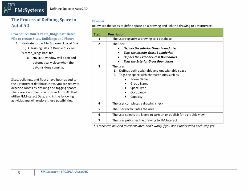
Process:
Below are the steps to define space on a drawing and link the drawing to FM:Interact:
Step
Description
1 The user registers a drawing to a database
2 The user:
• Defines the Interior Gross Boundaries
• Tags the Interior Gross Boundaries
• Defines the Exterior Gross Boundaries
• Tags the Exterior Gross Boundaries
3 The user: 1. Defines both assignable and unassignable space 2. Tags the space with characteristics such as:
• Room Name
• Group Name
• Space Type
• Occupancy
• Capacity
4 The user completes a drawing check
5 The user recalculates the area
6 The user selects the layers to turn on or publish for a graphic view
7 The user publishes the drawing to FM:Interact
This table can be used to review later, don’t worry if you don’t understand each step yet.
6 FM:Interact – SPC101A: AutoCAD
Activity 1: Defining Space Inventory for
the ThetaBeta Building Sites, buildings, and floors should have already been
added by the administrator. At this point we have
floors with no space designations and no area
calculations.
We are going to define and tag space on the 100-
01.dwg drawing.
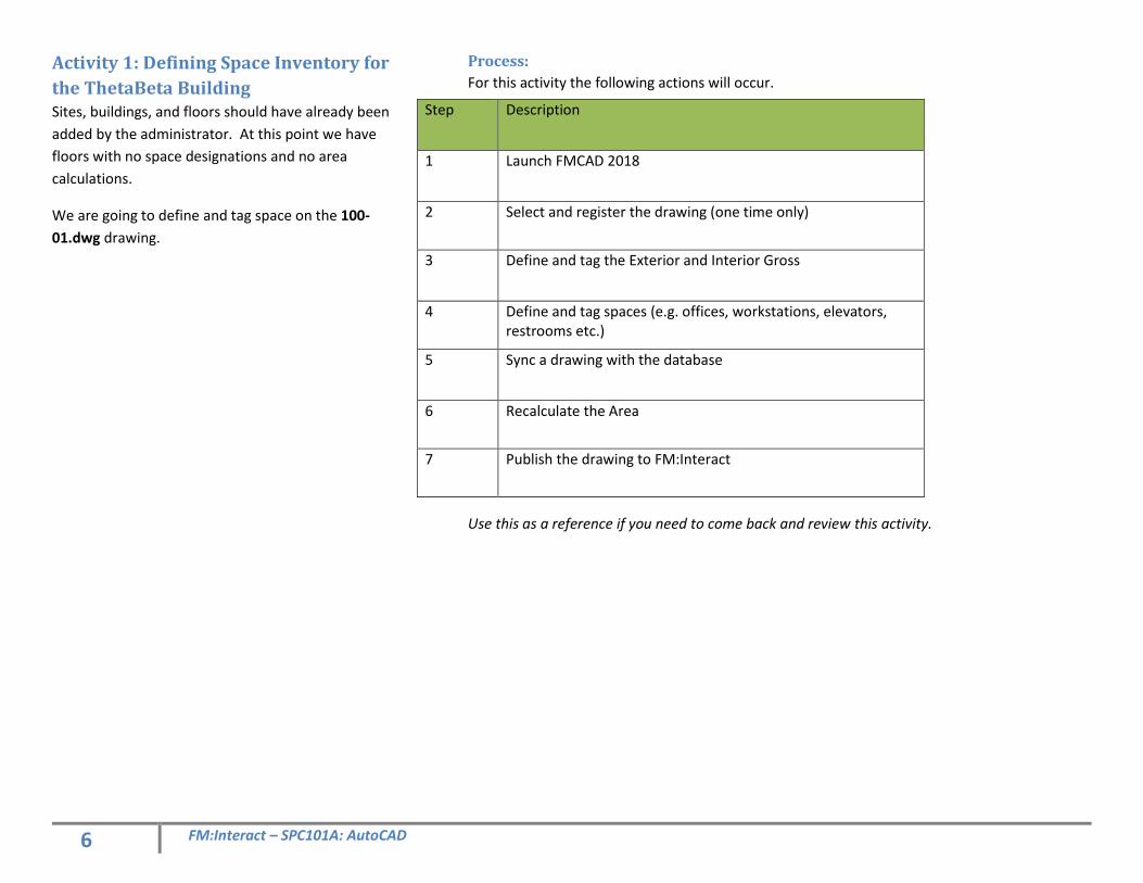
Process:
For this activity the following actions will occur.
Use this as a reference if you need to come back and review this activity.
Step Description
1 Launch FMCAD 2018
2 Select and register the drawing (one time only)
3 Define and tag the Exterior and Interior Gross
4 Define and tag spaces (e.g. offices, workstations, elevators, restrooms etc.)
5 Sync a drawing with the database
6 Recalculate the Area
7 Publish the drawing to FM:Interact
7 FM:Interact – SPC101A: AutoCAD
Activity 1, Part 1: Access and Register an
AutoCAD Drawing Your first task is to launch FM:CAD and register the drawing for the 1st floor of the ThetaBeta corporate office. Note: You only register the drawing the first time you open it in FM:CAD.
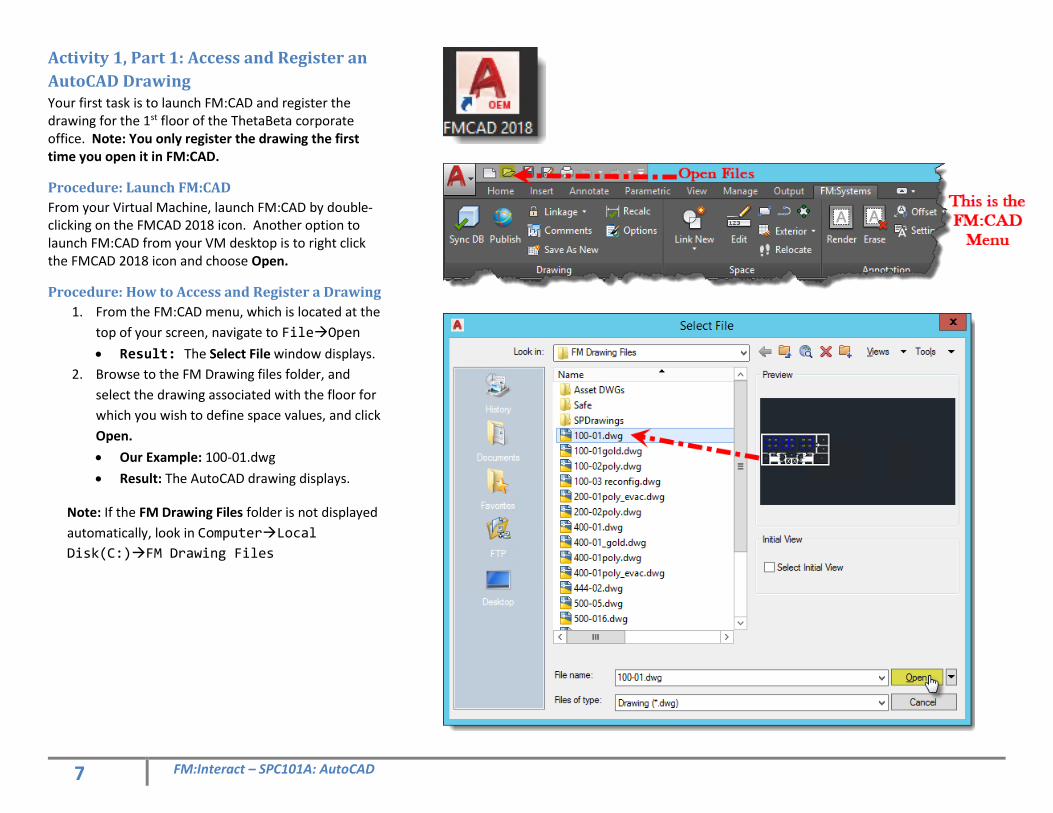
Procedure: Launch FM:CAD
From your Virtual Machine, launch FM:CAD by double-clicking on the FMCAD 2018 icon. Another option to launch FM:CAD from your VM desktop is to right click the FMCAD 2018 icon and choose Open.
Procedure: How to Access and Register a Drawing
1. From the FM:CAD menu, which is located at the
top of your screen, navigate to FileOpen
• Result: The Select File window displays.
2. Browse to the FM Drawing files folder, and
select the drawing associated with the floor for
which you wish to define space values, and click
Open.
• Our Example: 100-01.dwg
• Result: The AutoCAD drawing displays.
Note: If the FM Drawing Files folder is not displayed
automatically, look in ComputerLocal
Disk(C:)FM Drawing Files
8 FM:Interact – SPC101A: AutoCAD
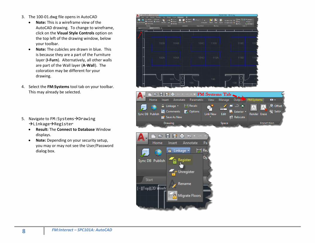
3. The 100-01.dwg file opens in AutoCAD
• Note: This is a wireframe view of the AutoCAD drawing. To change to wireframe, click on the Visual Style Controls option on the top left of the drawing window, below your toolbar.
• Note: The cubicles are drawn in blue. This is because they are a part of the Furniture layer (I-Furn). Alternatively, all other walls are part of the Wall layer (A-Wall). The coloration may be different for your drawing.
4. Select the FM:Systems tool tab on your toolbar.
This may already be selected.
5. Navigate to FM:SystemsDrawing LinkageRegister
• Result: The Connect to Database Window displays.
• Note: Depending on your security setup, you may or may not see the User/Password dialog box.
9 FM:Interact – SPC101A: AutoCAD
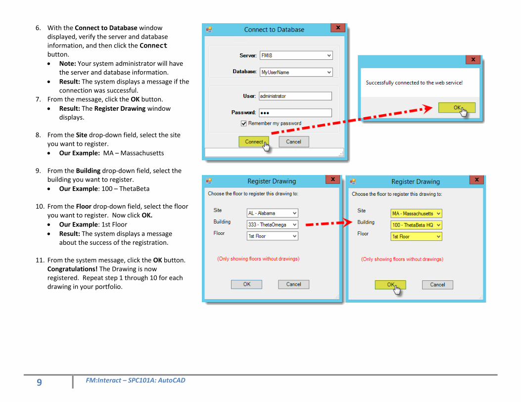
6. With the Connect to Database window displayed, verify the server and database information, and then click the Connect button.
• Note: Your system administrator will have the server and database information.
• Result: The system displays a message if the connection was successful.
7. From the message, click the OK button.
• Result: The Register Drawing window displays.
8. From the Site drop-down field, select the site you want to register.
• Our Example: MA – Massachusetts
9. From the Building drop-down field, select the building you want to register.
• Our Example: 100 – ThetaBeta
10. From the Floor drop-down field, select the floor you want to register. Now click OK.
• Our Example: 1st Floor
• Result: The system displays a message about the success of the registration.
11. From the system message, click the OK button. Congratulations! The Drawing is now registered. Repeat step 1 through 10 for each drawing in your portfolio.
10 FM:Interact – SPC101A: AutoCAD
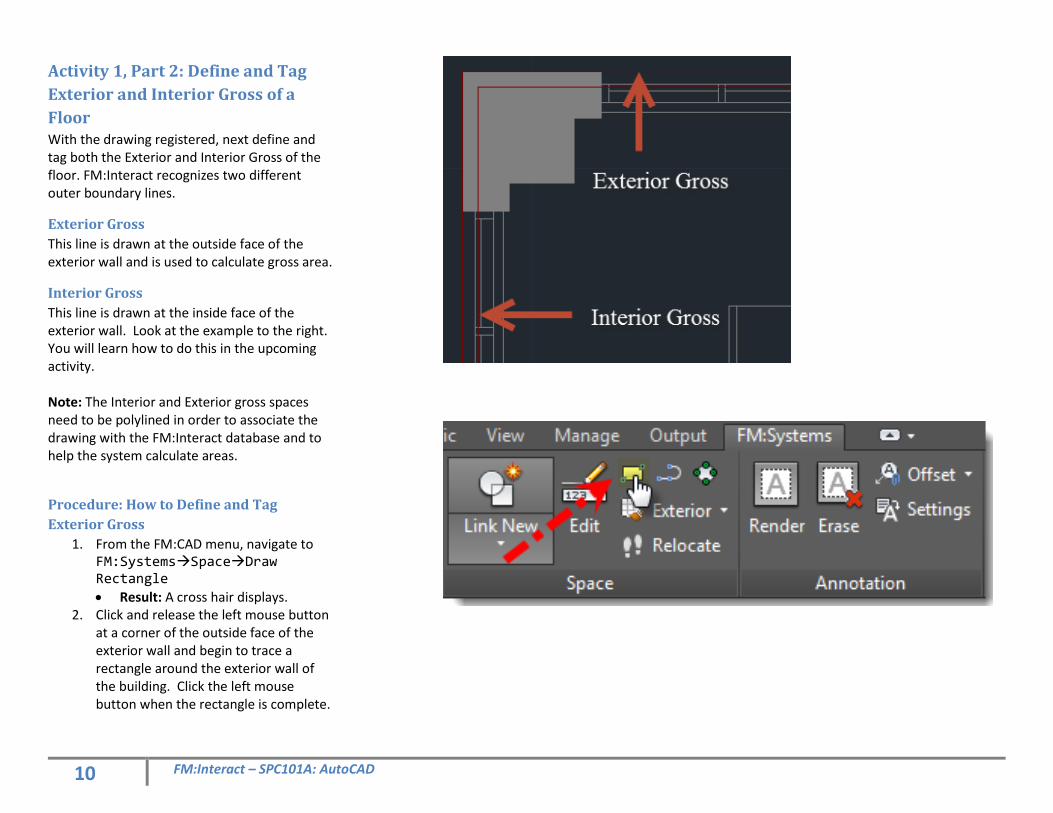
Activity 1, Part 2: Define and Tag
Exterior and Interior Gross of a
Floor With the drawing registered, next define and tag both the Exterior and Interior Gross of the floor. FM:Interact recognizes two different outer boundary lines.
Exterior Gross
This line is drawn at the outside face of the exterior wall and is used to calculate gross area.
Interior Gross
This line is drawn at the inside face of the exterior wall. Look at the example to the right. You will learn how to do this in the upcoming activity. Note: The Interior and Exterior gross spaces need to be polylined in order to associate the drawing with the FM:Interact database and to help the system calculate areas.
Procedure: How to Define and Tag
Exterior Gross
1. From the FM:CAD menu, navigate to FM:SystemsSpaceDraw Rectangle
• Result: A cross hair displays. 2. Click and release the left mouse button
at a corner of the outside face of the exterior wall and begin to trace a rectangle around the exterior wall of the building. Click the left mouse button when the rectangle is complete.
11 FM:Interact – SPC101A: AutoCAD
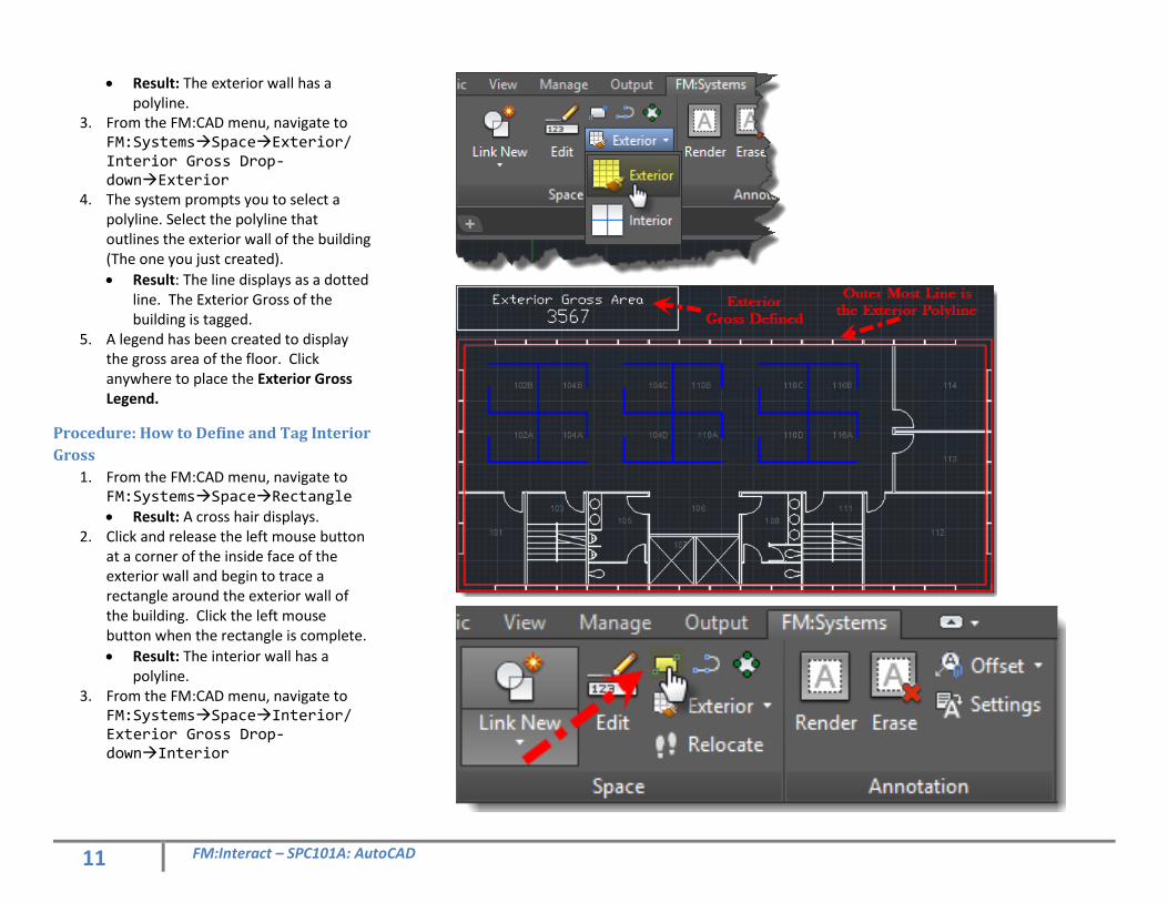
• Result: The exterior wall has a polyline.
3. From the FM:CAD menu, navigate to FM:SystemsSpaceExterior/ Interior Gross Drop-downExterior
4. The system prompts you to select a polyline. Select the polyline that outlines the exterior wall of the building (The one you just created).
• Result: The line displays as a dotted line. The Exterior Gross of the building is tagged.
5. A legend has been created to display the gross area of the floor. Click anywhere to place the Exterior Gross Legend.
Procedure: How to Define and Tag Interior
Gross
1. From the FM:CAD menu, navigate to FM:SystemsSpaceRectangle • Result: A cross hair displays.
2. Click and release the left mouse button at a corner of the inside face of the exterior wall and begin to trace a rectangle around the exterior wall of the building. Click the left mouse button when the rectangle is complete.
• Result: The interior wall has a polyline.
3. From the FM:CAD menu, navigate to FM:SystemsSpaceInterior/ Exterior Gross Drop-downInterior
12 FM:Interact – SPC101A: AutoCAD
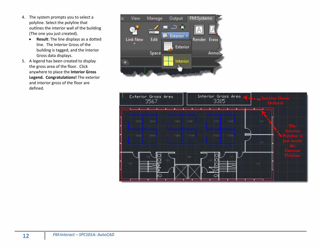
4. The system prompts you to select a polyline. Select the polyline that outlines the interior wall of the building (The one you just created).
• Result: The line displays as a dotted line. The Interior Gross of the building is tagged, and the Interior Gross data displays.
5. A legend has been created to display the gross area of the floor. Click anywhere to place the Interior Gross Legend. Congratulations! The exterior and interior gross of the floor are defined.
13 FM:Interact – SPC101A: AutoCAD
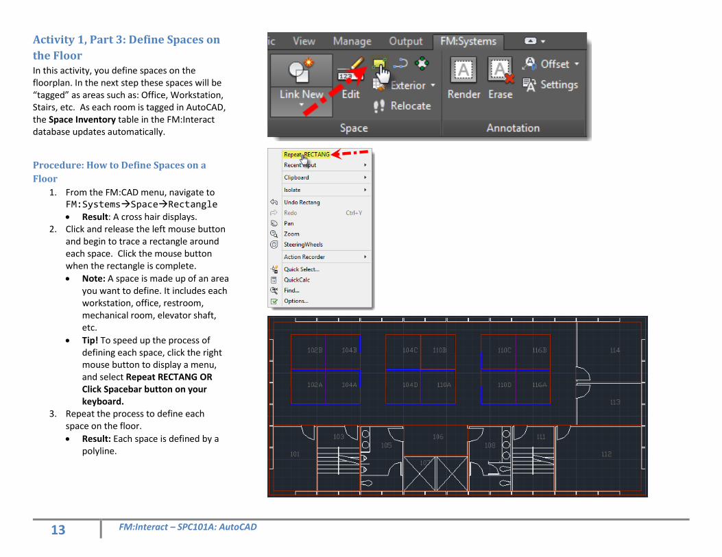
Activity 1, Part 3: Define Spaces on
the Floor In this activity, you define spaces on the floorplan. In the next step these spaces will be “tagged” as areas such as: Office, Workstation, Stairs, etc. As each room is tagged in AutoCAD, the Space Inventory table in the FM:Interact database updates automatically.
Procedure: How to Define Spaces on a
Floor
1. From the FM:CAD menu, navigate to FM:SystemsSpaceRectangle • Result: A cross hair displays.
2. Click and release the left mouse button and begin to trace a rectangle around each space. Click the mouse button when the rectangle is complete.
• Note: A space is made up of an area you want to define. It includes each workstation, office, restroom, mechanical room, elevator shaft, etc.
• Tip! To speed up the process of defining each space, click the right mouse button to display a menu, and select Repeat RECTANG OR Click Spacebar button on your keyboard.
3. Repeat the process to define each space on the floor.
• Result: Each space is defined by a polyline.
14 FM:Interact – SPC101A: AutoCAD
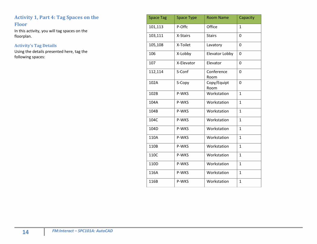
Activity 1, Part 4: Tag Spaces on the
Floor In this activity, you will tag spaces on the floorplan.
Activity’s Tag Details
Using the details presented here, tag the following spaces:
Space Tag Space Type Room Name Capacity
101,113 P-Offc Office 1
103,111 X-Stairs Stairs 0
105,108 X-Toilet Lavatory 0
106 X-Lobby Elevator Lobby 0
107 X-Elevator Elevator 0
112,114 S-Conf Conference Room
0
102A S-Copy Copy/Equipt Room
0
102B P-WKS Workstation 1
104A P-WKS Workstation 1
104B P-WKS Workstation 1
104C P-WKS Workstation 1
104D P-WKS Workstation 1
110A P-WKS Workstation 1
110B P-WKS Workstation 1
110C P-WKS Workstation 1
110D P-WKS Workstation 1
116A P-WKS Workstation 1
116B P-WKS Workstation 1
15 FM:Interact – SPC101A: AutoCAD
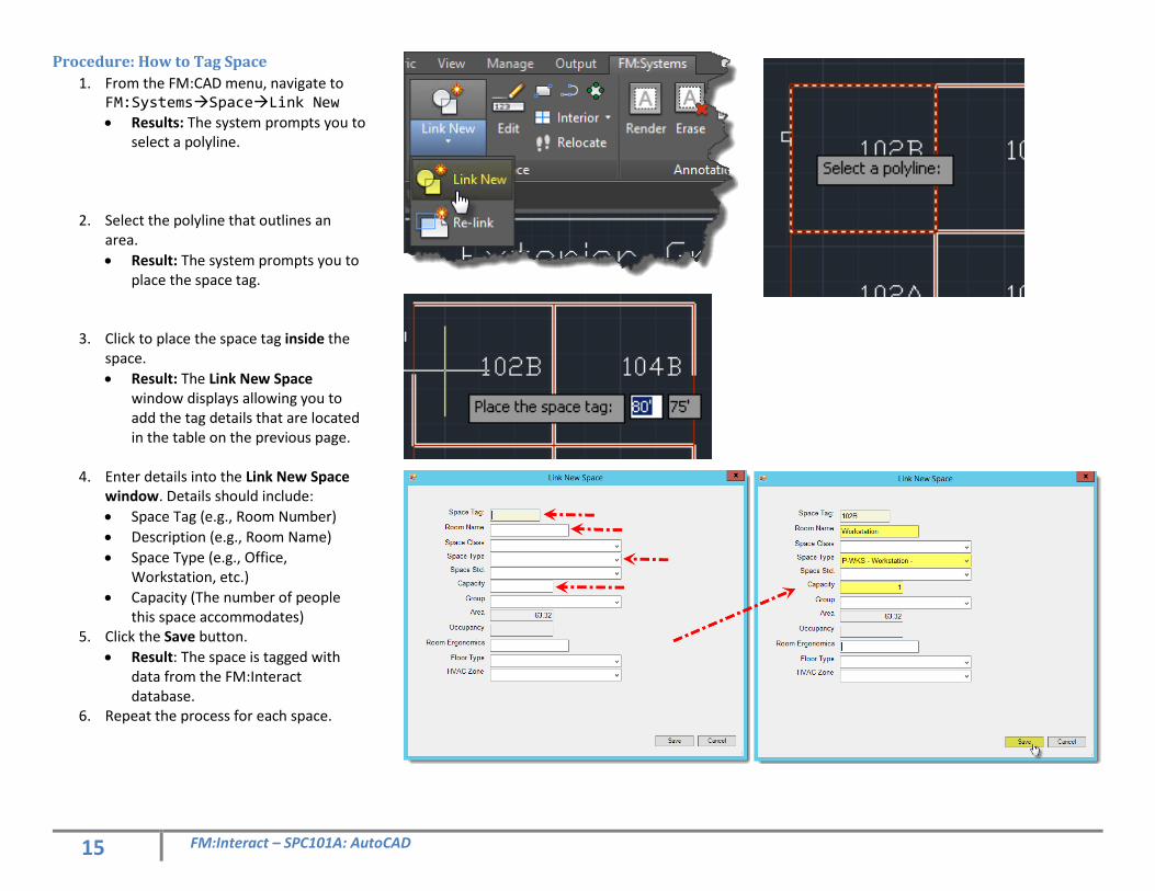
Procedure: How to Tag Space
1. From the FM:CAD menu, navigate to FM:SystemsSpaceLink New
• Results: The system prompts you to select a polyline.
2. Select the polyline that outlines an area.
• Result: The system prompts you to place the space tag.
3. Click to place the space tag inside the space.
• Result: The Link New Space window displays allowing you to add the tag details that are located in the table on the previous page.
4. Enter details into the Link New Space
window. Details should include:
• Space Tag (e.g., Room Number)
• Description (e.g., Room Name)
• Space Type (e.g., Office, Workstation, etc.)
• Capacity (The number of people this space accommodates)
5. Click the Save button.
• Result: The space is tagged with data from the FM:Interact database.
6. Repeat the process for each space.
16 FM:Interact – SPC101A: AutoCAD
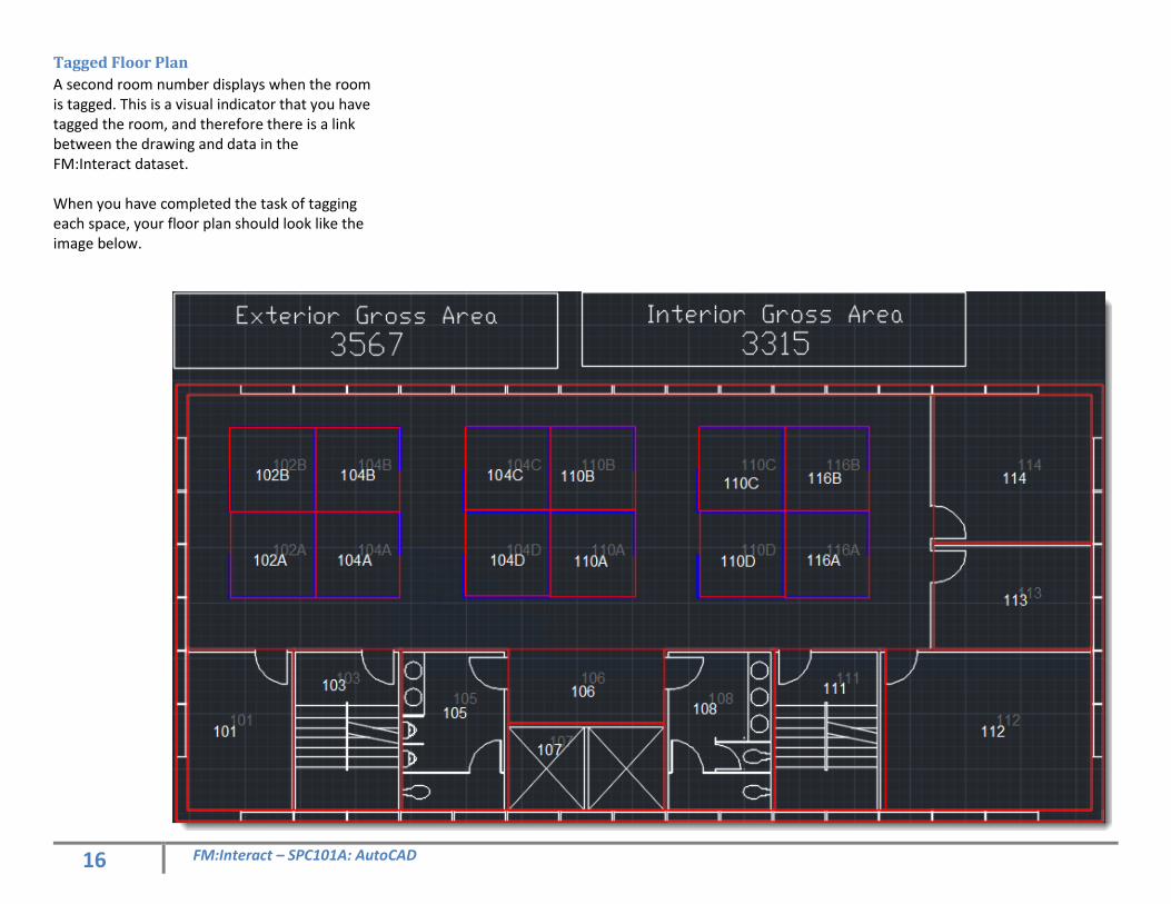
Tagged Floor Plan
A second room number displays when the room is tagged. This is a visual indicator that you have tagged the room, and therefore there is a link between the drawing and data in the FM:Interact dataset. When you have completed the task of tagging each space, your floor plan should look like the image below.
17 FM:Interact – SPC101A: AutoCAD
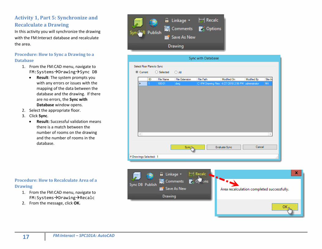
Activity 1, Part 5: Synchronize and
Recalculate a Drawing In this activity you will synchronize the drawing
with the FM:Interact database and recalculate
the area.
Procedure: How to Sync a Drawing to a
Database
1. From the FM:CAD menu, navigate to FM:SystemsDrawingSync DB
• Result: The system prompts you with any errors or issues with the mapping of the data between the database and the drawing. If there are no errors, the Sync with Database window opens.
2. Select the appropriate floor. 3. Click Sync.
• Result: Successful validation means there is a match between the number of rooms on the drawing and the number of rooms in the database.
Procedure: How to Recalculate Area of a
Drawing
1. From the FM:CAD menu, navigate to FM:SystemsDrawingRecalc
2. From the message, click OK.
18 FM:Interact – SPC101A: AutoCAD
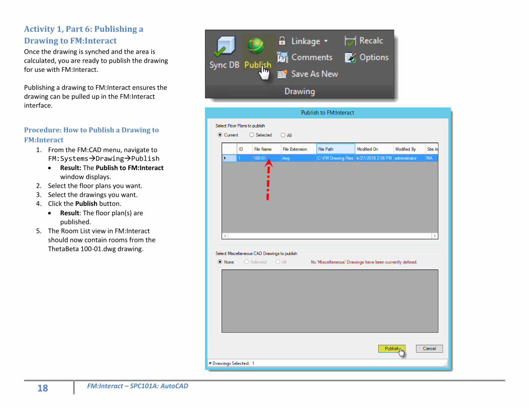
Activity 1, Part 6: Publishing a
Drawing to FM:Interact Once the drawing is synched and the area is calculated, you are ready to publish the drawing for use with FM:Interact. Publishing a drawing to FM:Interact ensures the drawing can be pulled up in the FM:Interact interface.
Procedure: How to Publish a Drawing to
FM:Interact
1. From the FM:CAD menu, navigate to FM:SystemsDrawingPublish • Result: The Publish to FM:Interact
window displays. 2. Select the floor plans you want. 3. Select the drawings you want. 4. Click the Publish button.
• Result: The floor plan(s) are published.
5. The Room List view in FM:Interact should now contain rooms from the ThetaBeta 100-01.dwg drawing.
Using the Auto Tag Routine
19 FM:Interact – SPC101A: AutoCAD
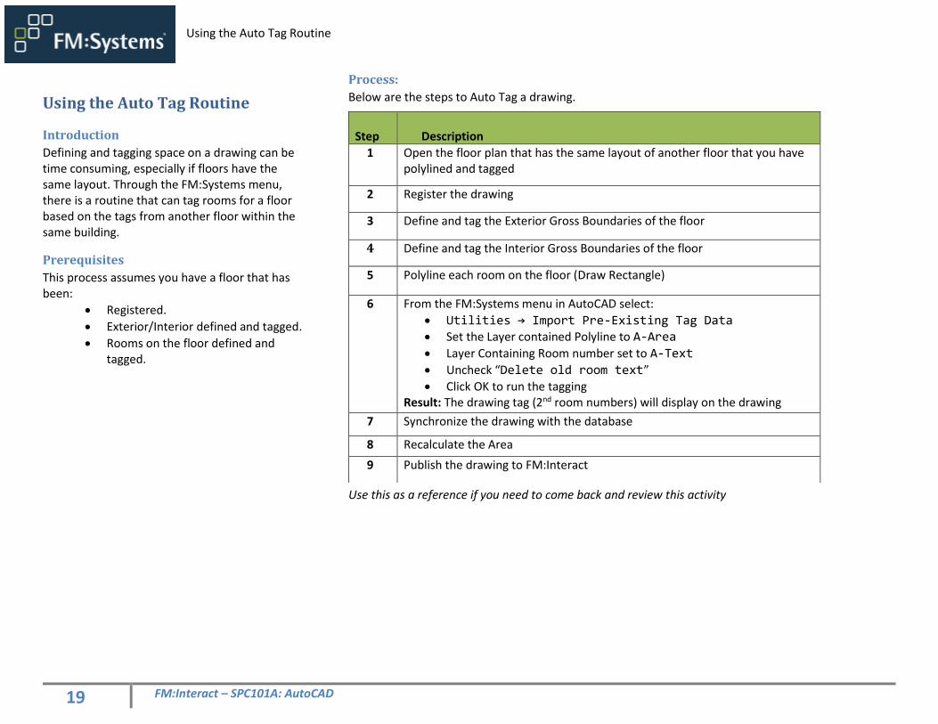
Using the Auto Tag Routine
Introduction
Defining and tagging space on a drawing can be time consuming, especially if floors have the same layout. Through the FM:Systems menu, there is a routine that can tag rooms for a floor based on the tags from another floor within the same building.
Prerequisites
This process assumes you have a floor that has been:
• Registered.
• Exterior/Interior defined and tagged.
• Rooms on the floor defined and tagged.
Process:
Below are the steps to Auto Tag a drawing.
Use this as a reference if you need to come back and review this activity
Step
Description
1 Open the floor plan that has the same layout of another floor that you have polylined and tagged
2 Register the drawing
3 Define and tag the Exterior Gross Boundaries of the floor
4 Define and tag the Interior Gross Boundaries of the floor
5 Polyline each room on the floor (Draw Rectangle)
6 From the FM:Systems menu in AutoCAD select:
• Utilities → Import Pre-Existing Tag Data
• Set the Layer contained Polyline to A-Area
• Layer Containing Room number set to A-Text
• Uncheck “Delete old room text”
• Click OK to run the tagging Result: The drawing tag (2nd room numbers) will display on the drawing
7 Synchronize the drawing with the database
8 Recalculate the Area
9 Publish the drawing to FM:Interact
20 FM:Interact – SPC101A: AutoCAD
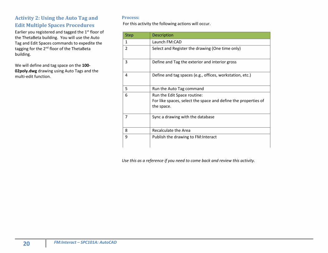
Activity 2: Using the Auto Tag and
Edit Multiple Spaces Procedures Earlier you registered and tagged the 1st floor of the ThetaBeta building. You will use the Auto Tag and Edit Spaces commands to expedite the tagging for the 2nd floor of the ThetaBeta building. We will define and tag space on the 100-02poly.dwg drawing using Auto Tags and the multi-edit function.
Process:
For this activity the following actions will occur.
Use this as a reference if you need to come back and review this activity.
Step Description
1 Launch FM:CAD
2 Select and Register the drawing (One time only)
3 Define and Tag the exterior and interior gross
4 Define and tag spaces (e.g., offices, workstation, etc.)
5 Run the Auto Tag command
6 Run the Edit Space routine: For like spaces, select the space and define the properties of the space.
7 Sync a drawing with the database
8 Recalculate the Area
9 Publish the drawing to FM:Interact
21 FM:Interact – SPC101A: AutoCAD
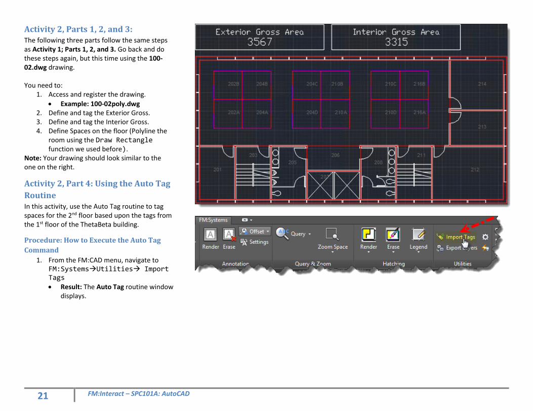
Activity 2, Parts 1, 2, and 3: The following three parts follow the same steps as Activity 1; Parts 1, 2, and 3. Go back and do these steps again, but this time using the 100-02.dwg drawing. You need to:
1. Access and register the drawing.
• Example: 100-02poly.dwg 2. Define and tag the Exterior Gross. 3. Define and tag the Interior Gross. 4. Define Spaces on the floor (Polyline the
room using the Draw Rectangle function we used before).
Note: Your drawing should look similar to the one on the right.
Activity 2, Part 4: Using the Auto Tag
Routine In this activity, use the Auto Tag routine to tag spaces for the 2nd floor based upon the tags from the 1st floor of the ThetaBeta building.
Procedure: How to Execute the Auto Tag
Command
1. From the FM:CAD menu, navigate to FM:SystemsUtilities Import Tags • Result: The Auto Tag routine window
displays.
22 FM:Interact – SPC101A: AutoCAD
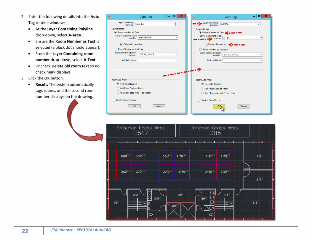
2. Enter the following details into the Auto
Tag routine window:
• At the Layer Containing Polyline
drop-down, select A-Area.
• Ensure the Room Number as Text is
selected (a black dot should appear).
• From the Layer Containing room
number drop-down, select A-Text.
• Uncheck Delete old room text so no
check mark displays.
3. Click the OK button.
• Result: The system automatically
tags rooms, and the second room
number displays on the drawing.
23 FM:Interact – SPC101A: AutoCAD
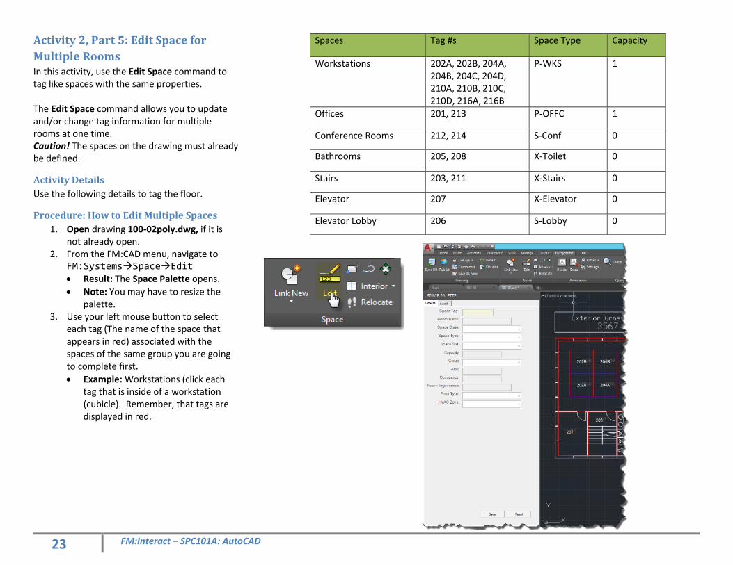
Activity 2, Part 5: Edit Space for
Multiple Rooms In this activity, use the Edit Space command to tag like spaces with the same properties. The Edit Space command allows you to update and/or change tag information for multiple rooms at one time. Caution! The spaces on the drawing must already be defined.
Activity Details
Use the following details to tag the floor.
Procedure: How to Edit Multiple Spaces
1. Open drawing 100-02poly.dwg, if it is not already open.
2. From the FM:CAD menu, navigate to FM:SystemsSpaceEdit • Result: The Space Palette opens.
• Note: You may have to resize the palette.
3. Use your left mouse button to select each tag (The name of the space that appears in red) associated with the spaces of the same group you are going to complete first.
• Example: Workstations (click each tag that is inside of a workstation (cubicle). Remember, that tags are displayed in red.
Spaces Tag #s Space Type Capacity
Workstations 202A, 202B, 204A, 204B, 204C, 204D, 210A, 210B, 210C, 210D, 216A, 216B
P-WKS 1
Offices 201, 213 P-OFFC 1
Conference Rooms 212, 214 S-Conf 0
Bathrooms 205, 208 X-Toilet 0
Stairs 203, 211 X-Stairs 0
Elevator 207 X-Elevator 0
Elevator Lobby 206 S-Lobby 0
24 FM:Interact – SPC101A: AutoCAD
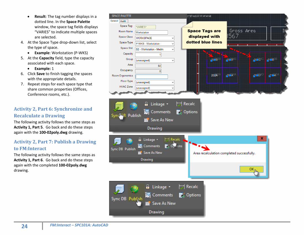
• Result: The tag number displays in a dotted line. In the Space Palette window, the space tag fields displays “VARIES” to indicate multiple spaces are selected.
4. At the Space Type drop-down list, select the type of space.
• Example: Workstation (P-WKS) 5. At the Capacity field, type the capacity
associated with each space.
• Example: 1 6. Click Save to finish tagging the spaces
with the appropriate details. 7. Repeat steps for each space type that
share common properties (Offices, Conference rooms, etc.).
Activity 2, Part 6: Synchronize and
Recalculate a Drawing The following activity follows the same steps as Activity 1, Part 5. Go back and do these steps again with the 100-02poly.dwg drawing.
Activity 2, Part 7: Publish a Drawing
to FM:Interact The following activity follows the same steps as Activity 1, Part 6. Go back and do these steps again with the completed 100-02poly.dwg drawing.
Enhancing AutoCAD with FM:Interact Data
25 FM:Interact – SPC101A: AutoCAD
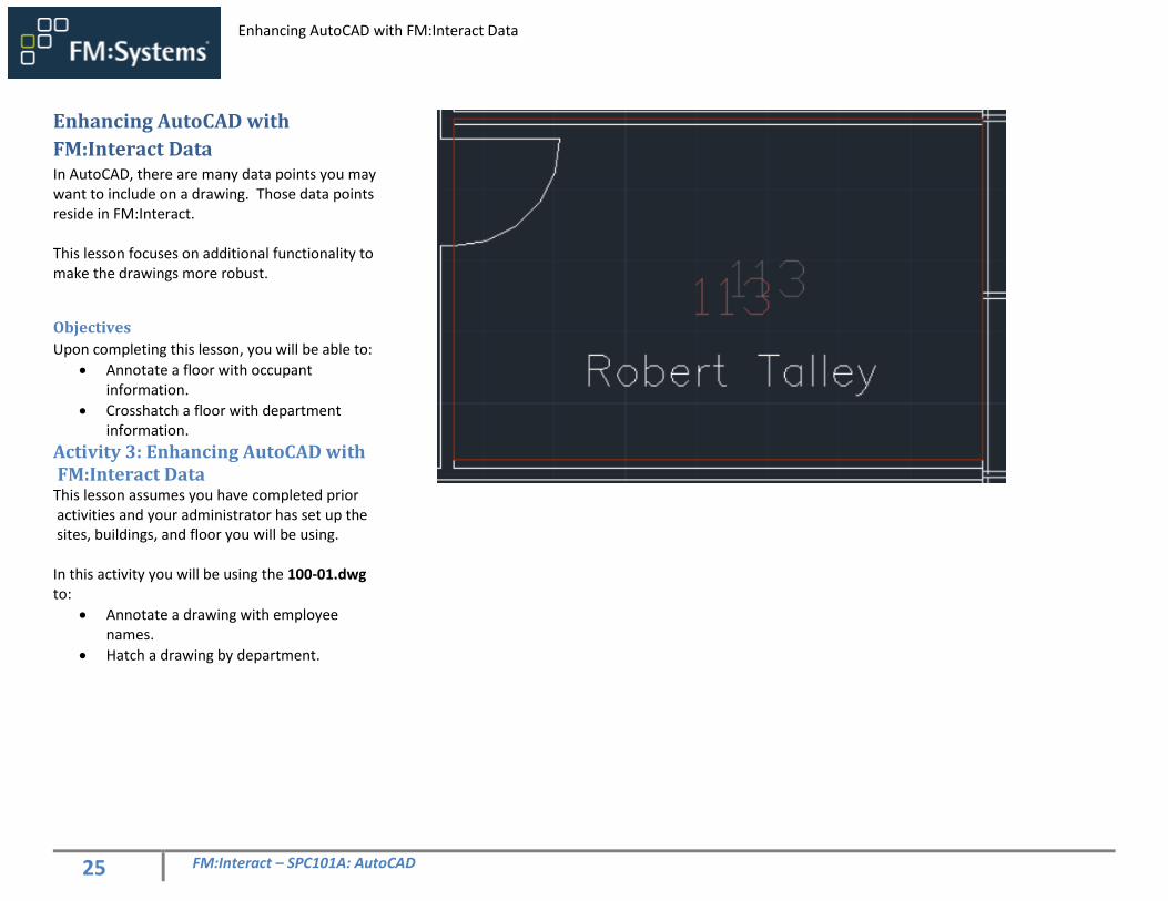
Enhancing AutoCAD with
FM:Interact Data In AutoCAD, there are many data points you may want to include on a drawing. Those data points reside in FM:Interact. This lesson focuses on additional functionality to make the drawings more robust.
Objectives
Upon completing this lesson, you will be able to:
• Annotate a floor with occupant information.
• Crosshatch a floor with department information.
Activity 3: Enhancing AutoCAD with FM:Interact Data This lesson assumes you have completed prior activities and your administrator has set up the sites, buildings, and floor you will be using. In this activity you will be using the 100-01.dwg to:
• Annotate a drawing with employee names.
• Hatch a drawing by department.
26 FM:Interact – SPC101A: AutoCAD
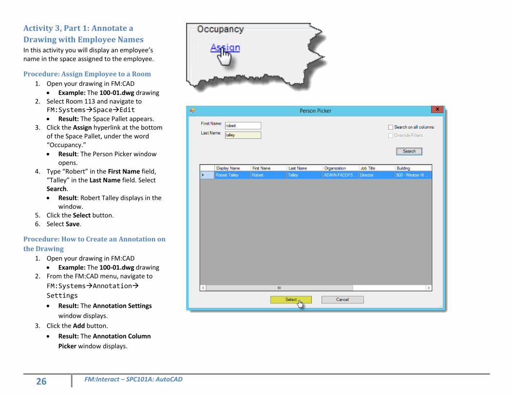
Activity 3, Part 1: Annotate a
Drawing with Employee Names In this activity you will display an employee’s name in the space assigned to the employee.
Procedure: Assign Employee to a Room
1. Open your drawing in FM:CAD
• Example: The 100-01.dwg drawing 2. Select Room 113 and navigate to
FM:SystemsSpaceEdit
• Result: The Space Pallet appears. 3. Click the Assign hyperlink at the bottom
of the Space Pallet, under the word “Occupancy.”
• Result: The Person Picker window opens.
4. Type “Robert” in the First Name field, “Talley” in the Last Name field. Select Search.
• Result: Robert Talley displays in the window.
5. Click the Select button. 6. Select Save.
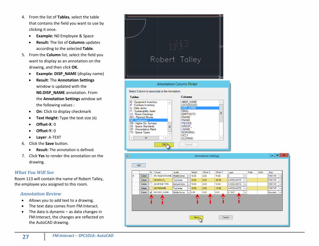
Procedure: How to Create an Annotation on
the Drawing
1. Open your drawing in FM:CAD
• Example: The 100-01.dwg drawing 2. From the FM:CAD menu, navigate to
FM:SystemsAnnotation
Settings
• Result: The Annotation Settings
window displays.
3. Click the Add button.
• Result: The Annotation Column
Picker window displays.
27 FM:Interact – SPC101A: AutoCAD
4. From the list of Tables, select the table
that contains the field you want to use by
clicking it once.
• Example: N0 Employee & Space
• Result: The list of Columns updates
according to the selected Table.
5. From the Column list, select the field you
want to display as an annotation on the
drawing, and then click OK.
• Example: DISP_NAME (display name)
• Result: The Annotation Settings
window is updated with the
N0.DISP_NAME annotation. From
the Annotation Settings window set
the following values :
• On: Click to display checkmark
• Text Height: Type the text size (6)
• Offset-X: 0
• Offset-Y: 0
• Layer: A-TEXT
6. Click the Save button.
• Result: The annotation is defined.
7. Click Yes to render the annotation on the
drawing.
What You Will See
Room 113 will contain the name of Robert Talley, the employee you assigned to this room.
Annotation Review
• Allows you to add text to a drawing.
• The text data comes from FM:Interact.
• The data is dynamic – as data changes in FM:Interact, the changes are reflected on the AutoCAD drawing.
28 FM:Interact – SPC101A: AutoCAD
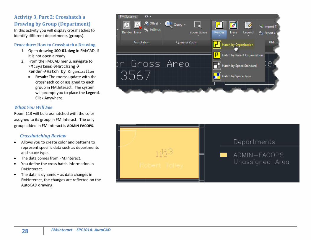
Activity 3, Part 2: Crosshatch a
Drawing by Group (Department) In this activity you will display crosshatches to identify different departments (groups).
Procedure: How to Crosshatch a Drawing
1. Open drawing 100-01.dwg in FM:CAD, if it is not open already.
2. From the FM:CAD menu, navigate to FM:SystemsHatching RenderHatch by Organization
• Result: The rooms update with the crosshatch color assigned to each group in FM:Interact. The system will prompt you to place the Legend. Click Anywhere.
What You Will See
Room 113 will be crosshatched with the color
assigned to its group in FM:Interact. The only
group added in FM:Interact is ADMIN-FACOPS.
Crosshatching Review
• Allows you to create color and patterns to represent specific data such as departments and space type.
• The data comes from FM:Interact.
• You define the cross hatch information in FM:Interact.
• The data is dynamic – as data changes in FM:Interact, the changes are reflected on the AutoCAD drawing.
29 FM:Interact – SPC101A: AutoCAD
Activity 3, Part 3: Define and Set a
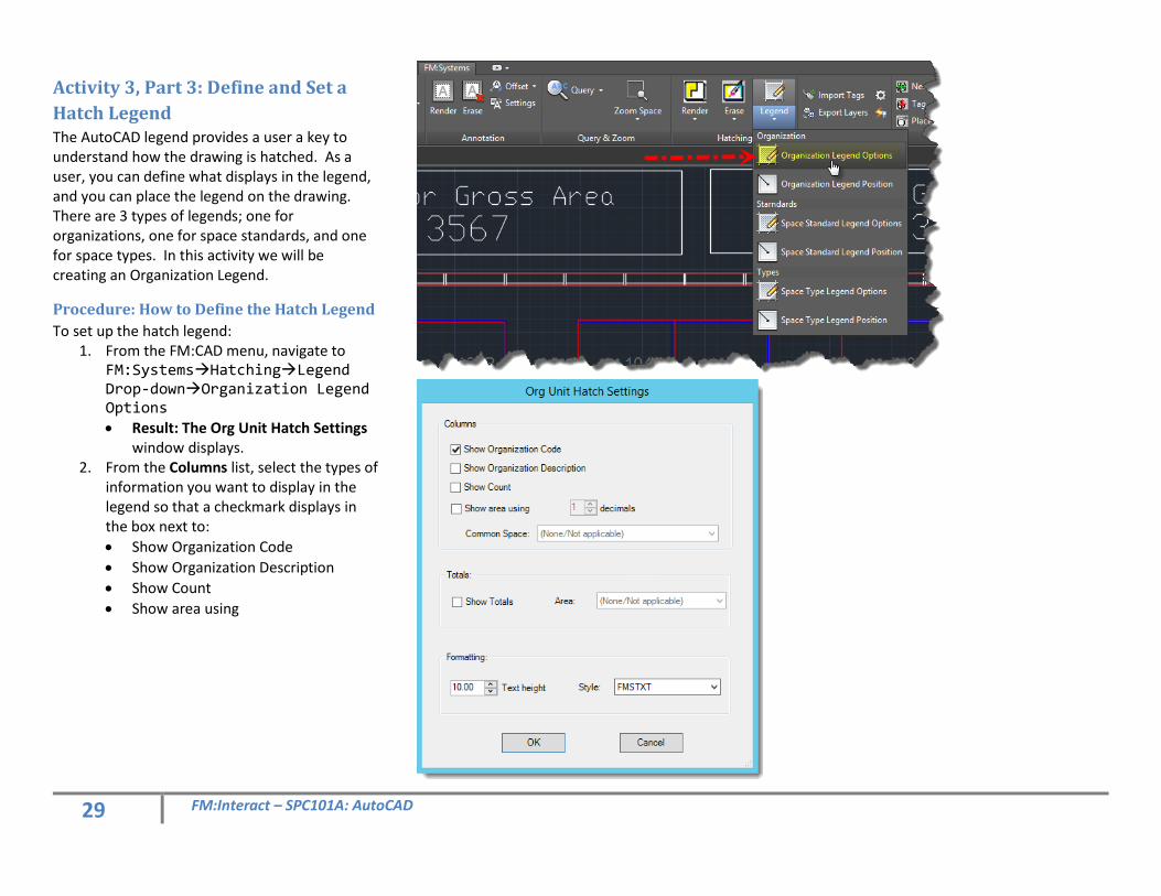
Hatch Legend The AutoCAD legend provides a user a key to understand how the drawing is hatched. As a user, you can define what displays in the legend, and you can place the legend on the drawing. There are 3 types of legends; one for organizations, one for space standards, and one for space types. In this activity we will be creating an Organization Legend.
Procedure: How to Define the Hatch Legend
To set up the hatch legend: 1. From the FM:CAD menu, navigate to
FM:SystemsHatchingLegend Drop-downOrganization Legend Options • Result: The Org Unit Hatch Settings
window displays. 2. From the Columns list, select the types of
information you want to display in the legend so that a checkmark displays in the box next to:
• Show Organization Code
• Show Organization Description
• Show Count
• Show area using
30 FM:Interact – SPC101A: AutoCAD
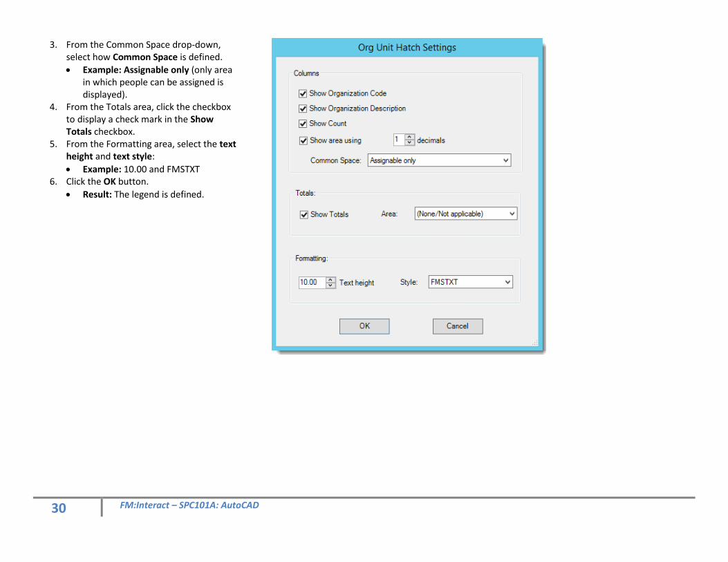
3. From the Common Space drop-down, select how Common Space is defined.
• Example: Assignable only (only area in which people can be assigned is displayed).
4. From the Totals area, click the checkbox to display a check mark in the Show Totals checkbox.
5. From the Formatting area, select the text height and text style:
• Example: 10.00 and FMSTXT 6. Click the OK button.
• Result: The legend is defined.
31 FM:Interact – SPC101A: AutoCAD
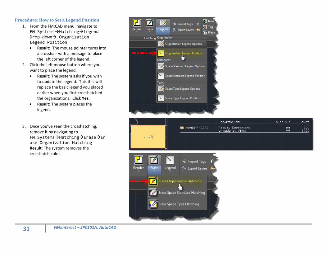
Procedure: How to Set a Legend Position
1. From the FM:CAD menu, navigate to FM:SystemsHatchingLegend Drop-down Organization Legend Position
• Result: The mouse pointer turns into a crosshair with a message to place the left corner of the legend.
2. Click the left mouse button where you want to place the legend.
• Result: The system asks if you wish to update the legend. This this will replace the basic legend you placed earlier when you first crosshatched the organizations. Click Yes.
• Result: The system places the legend.
3. Once you’ve seen the crosshatching, remove it by navigating to FM:SystemsHatchingEraseErase Organization Hatching Result: The system removes the crosshatch color.
Reconfiguring Space
32 FM:Interact – SPC101A: AutoCAD
Queries in AutoCAD Within AutoCAD, you can create queries that will display as output on AutoCAD drawings. Queries are searches that use specific criteria to find information. Queries can be used and created in both FM:Interact and AutoCAD.
Public Queries
Within AutoCAD, you can use pre-defined queries. These Queries are also called Public queries, as all Users have access to them. They are defined by an FM:Interact Administrator and used throughout the system.
Private Queries
Within AutoCAD, you can create user-defined queries. These queries are also called Private queries because they are defined by a single User, and only available to use within their FM:Interact system. Note: On a single drawing, you can have the results of more than one User Defined Query display. Note: If you are familiar with queries in FM:Interact, queries in AutoCAD follow the same format and logic as those built in FM:Interact.
33 FM:Interact – SPC101A: AutoCAD
Activity 4: Building Queries in
AutoCAD
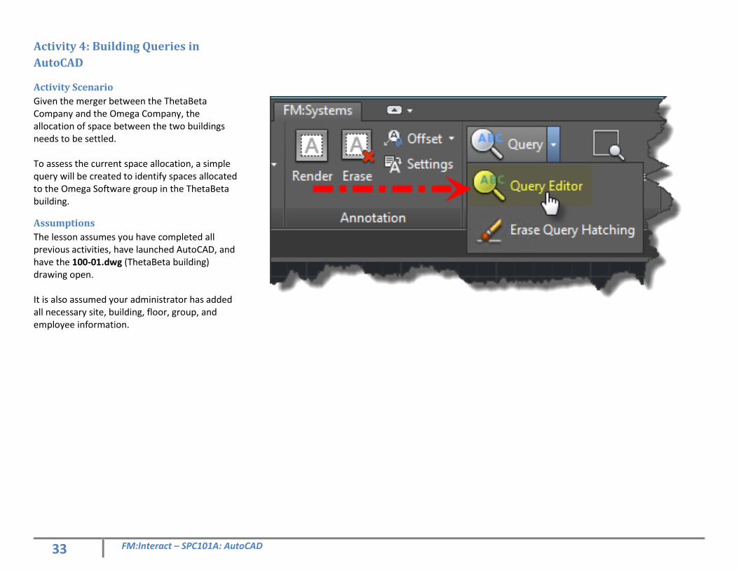
Activity Scenario
Given the merger between the ThetaBeta Company and the Omega Company, the allocation of space between the two buildings needs to be settled. To assess the current space allocation, a simple query will be created to identify spaces allocated to the Omega Software group in the ThetaBeta building.
Assumptions
The lesson assumes you have completed all previous activities, have launched AutoCAD, and have the 100-01.dwg (ThetaBeta building) drawing open. It is also assumed your administrator has added all necessary site, building, floor, group, and employee information.
34 FM:Interact – SPC101A: AutoCAD
Activity 4, Part 1: Create a User
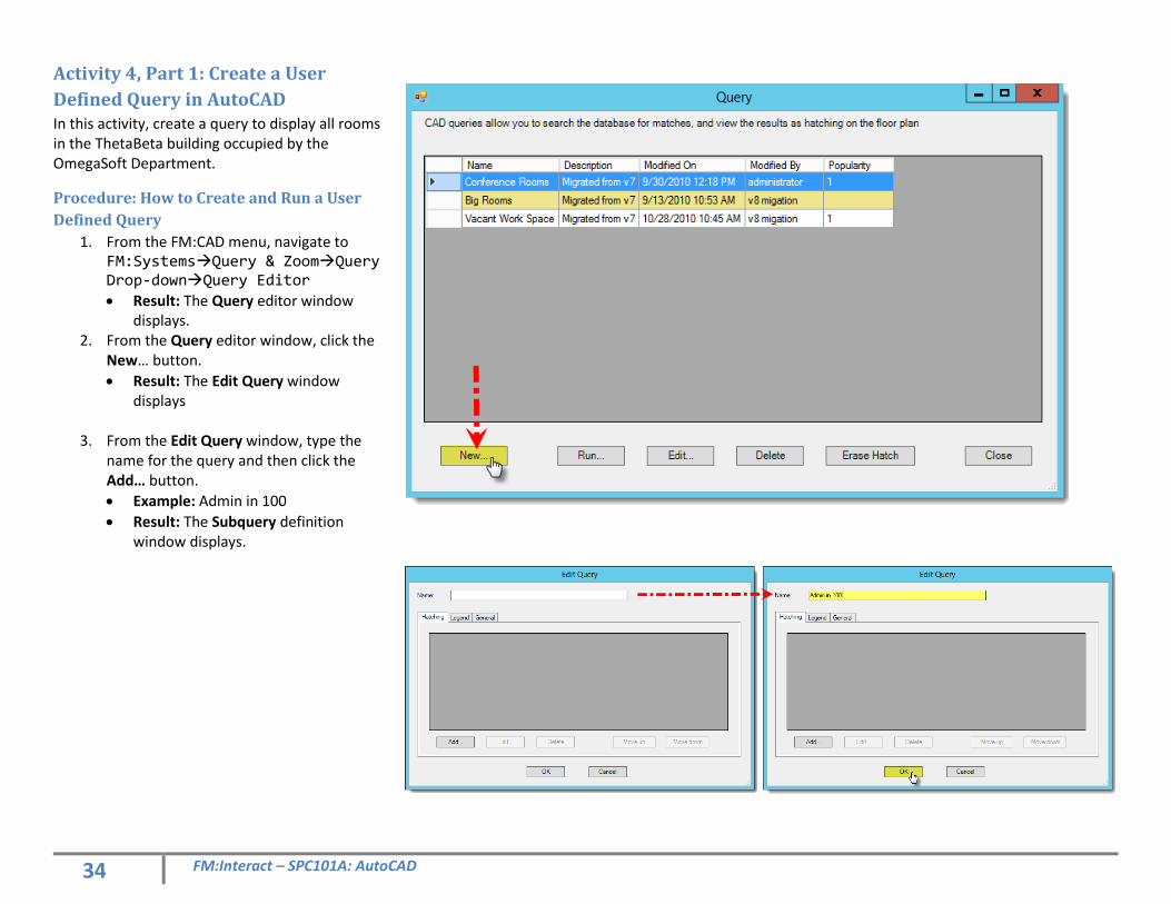
Defined Query in AutoCAD In this activity, create a query to display all rooms in the ThetaBeta building occupied by the OmegaSoft Department.
Procedure: How to Create and Run a User
Defined Query
1. From the FM:CAD menu, navigate to FM:SystemsQuery & ZoomQuery Drop-downQuery Editor
• Result: The Query editor window displays.
2. From the Query editor window, click the New… button.
• Result: The Edit Query window displays
3. From the Edit Query window, type the
name for the query and then click the Add… button.
• Example: Admin in 100
• Result: The Subquery definition window displays.
35 FM:Interact – SPC101A: AutoCAD
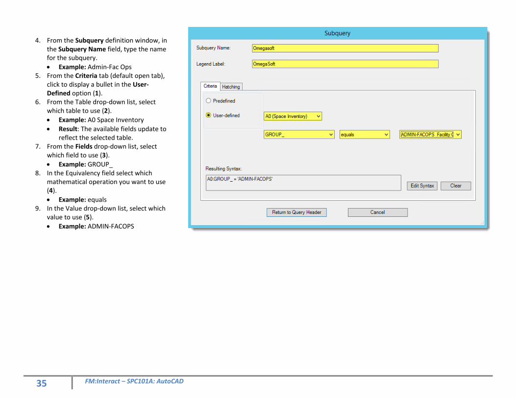
4. From the Subquery definition window, in
the Subquery Name field, type the name for the subquery.
• Example: Admin-Fac Ops 5. From the Criteria tab (default open tab),
click to display a bullet in the User-Defined option (1).
6. From the Table drop-down list, select which table to use (2).
• Example: A0 Space Inventory
• Result: The available fields update to reflect the selected table.
7. From the Fields drop-down list, select which field to use (3).
• Example: GROUP_ 8. In the Equivalency field select which
mathematical operation you want to use (4).
• Example: equals 9. In the Value drop-down list, select which
value to use (5).
• Example: ADMIN-FACOPS
36 FM:Interact – SPC101A: AutoCAD
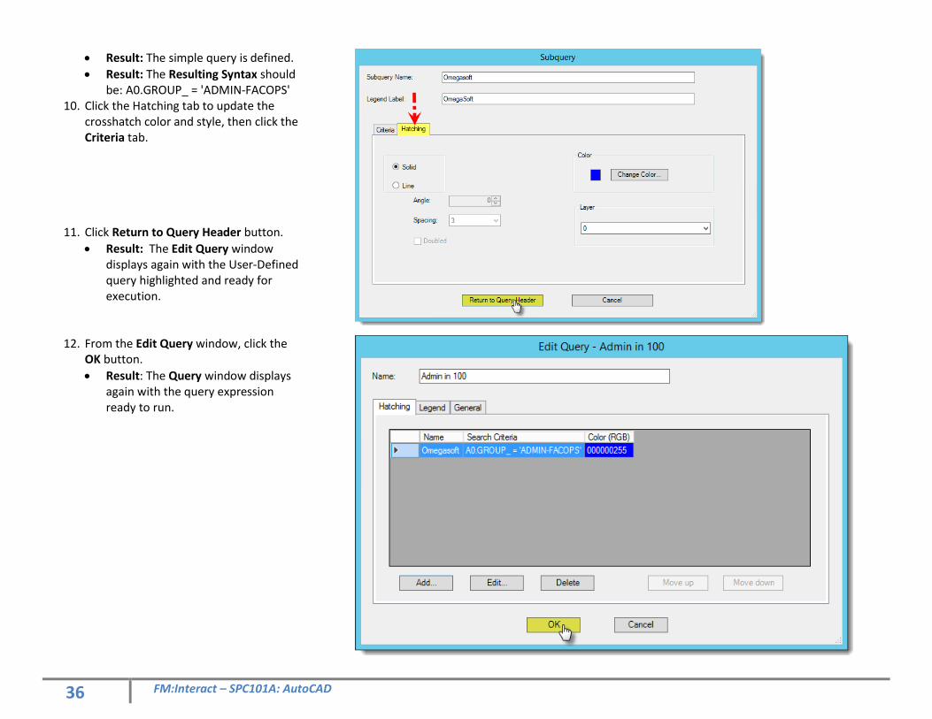
• Result: The simple query is defined.
• Result: The Resulting Syntax should be: A0.GROUP_ = 'ADMIN-FACOPS'
10. Click the Hatching tab to update the crosshatch color and style, then click the Criteria tab.
11. Click Return to Query Header button.
• Result: The Edit Query window displays again with the User-Defined query highlighted and ready for execution.
12. From the Edit Query window, click the OK button.
• Result: The Query window displays again with the query expression ready to run.
37 FM:Interact – SPC101A: AutoCAD
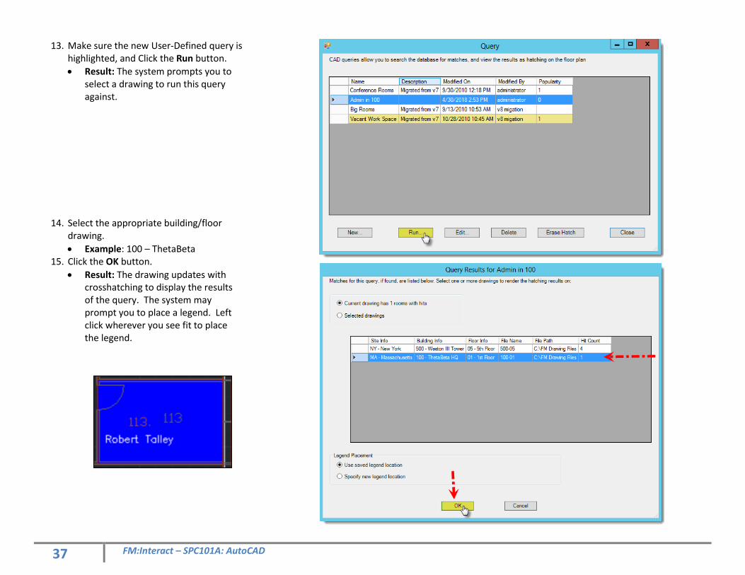
13. Make sure the new User-Defined query is highlighted, and Click the Run button.
• Result: The system prompts you to select a drawing to run this query against.
14. Select the appropriate building/floor drawing.
• Example: 100 – ThetaBeta 15. Click the OK button.
• Result: The drawing updates with crosshatching to display the results of the query. The system may prompt you to place a legend. Left click wherever you see fit to place the legend.
38 FM:Interact – SPC101A: AutoCAD
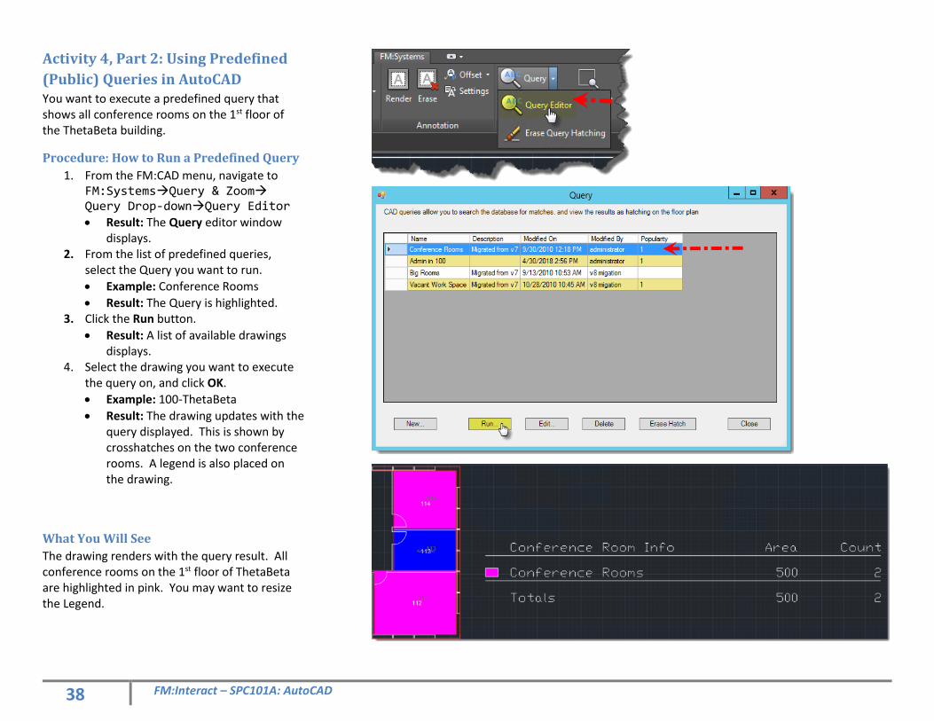
Activity 4, Part 2: Using Predefined
(Public) Queries in AutoCAD You want to execute a predefined query that shows all conference rooms on the 1st floor of the ThetaBeta building.
Procedure: How to Run a Predefined Query
1. From the FM:CAD menu, navigate to FM:SystemsQuery & Zoom Query Drop-downQuery Editor
• Result: The Query editor window displays.
2. From the list of predefined queries, select the Query you want to run.
• Example: Conference Rooms
• Result: The Query is highlighted. 3. Click the Run button.
• Result: A list of available drawings displays.
4. Select the drawing you want to execute the query on, and click OK.
• Example: 100-ThetaBeta
• Result: The drawing updates with the query displayed. This is shown by crosshatches on the two conference rooms. A legend is also placed on the drawing.
What You Will See
The drawing renders with the query result. All conference rooms on the 1st floor of ThetaBeta are highlighted in pink. You may want to resize the Legend.
39 FM:Interact – SPC101A: AutoCAD
Reconfiguring Space Over time, floor plans change. You need to ensure that both AutoCAD and FM:Interact accurately reflect the changes to space configuration.
Lesson Objectives
Upon completing this lesson, you will be able to:
• Define the process of updating AutoCAD and FM:Interact to reflect changes in space configuration.
• Demonstrate how to make changes in AutoCAD to reflect space reconfiguration.
• Look up in FM:Interact how changes in AutoCAD affect the database.
Activity 5: Reconfiguring Space (ThetaBeta Building, Floor 2)
The purpose of this activity is to show how to reconfigure space in AutoCAD, and, using integration between AutoCAD and FM:Interact, ensure FM:Interact updates with the reconfigured data.
Assumptions
The lesson assumes you have completed all previous activities, have launched AutoCAD, and have the 100-02.dwg (ThetaBeta building) drawing open.
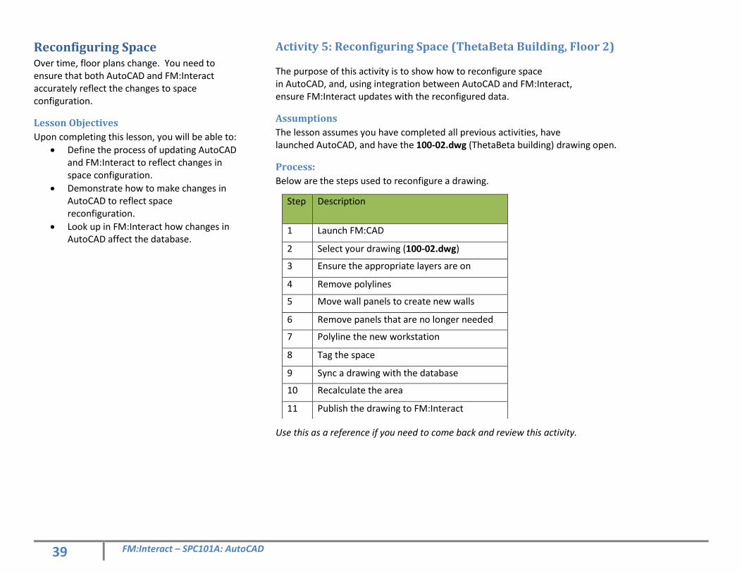
Process:
Below are the steps used to reconfigure a drawing.
Use this as a reference if you need to come back and review this activity.
Step Description
1 Launch FM:CAD
2 Select your drawing (100-02.dwg)
3 Ensure the appropriate layers are on
4 Remove polylines
5 Move wall panels to create new walls
6 Remove panels that are no longer needed
7 Polyline the new workstation
8 Tag the space
9 Sync a drawing with the database
10 Recalculate the area
11 Publish the drawing to FM:Interact
40 FM:Interact – SPC101A: AutoCAD
Activity 5, Part 1: Reconfigure
Workstations In this activity, you will reconfigure cubicles found on the 2nd floor of the ThetaBeta building (100-02.dwg)
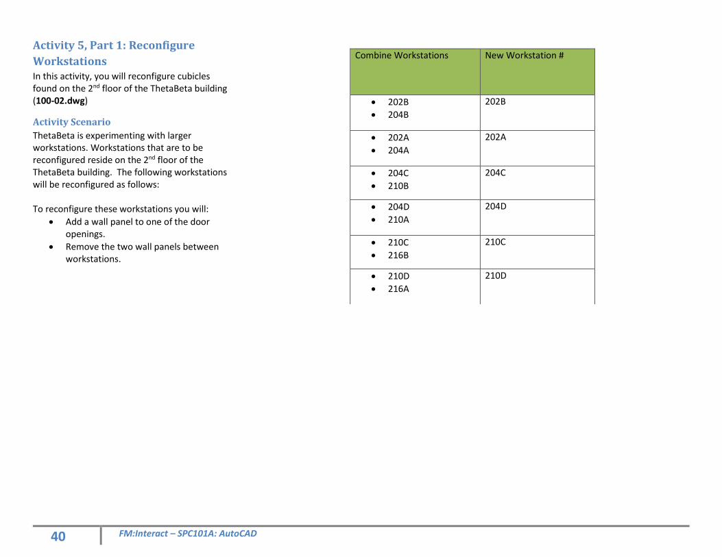
Activity Scenario
ThetaBeta is experimenting with larger workstations. Workstations that are to be reconfigured reside on the 2nd floor of the ThetaBeta building. The following workstations will be reconfigured as follows: To reconfigure these workstations you will:
• Add a wall panel to one of the door openings.
• Remove the two wall panels between workstations.
Combine Workstations New Workstation #
• 202B
• 204B
202B
• 202A
• 204A
202A
• 204C
• 210B
204C
• 204D
• 210A
204D
• 210C
• 216B
210C
• 210D
• 216A
210D
41 FM:Interact – SPC101A: AutoCAD
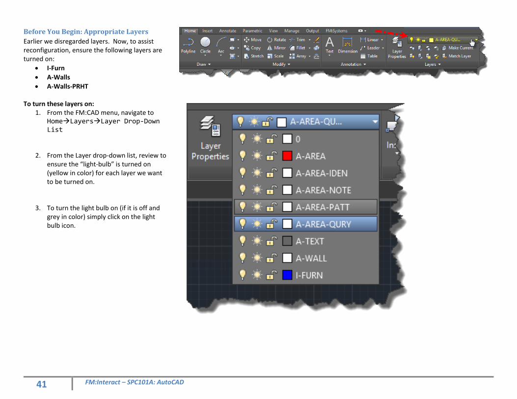
Before You Begin: Appropriate Layers
Earlier we disregarded layers. Now, to assist reconfiguration, ensure the following layers are turned on:
• I-Furn
• A-Walls
• A-Walls-PRHT To turn these layers on:
1. From the FM:CAD menu, navigate to HomeLayersLayer Drop-Down List
2. From the Layer drop-down list, review to ensure the “light-bulb” is turned on (yellow in color) for each layer we want to be turned on.
3. To turn the light bulb on (if it is off and grey in color) simply click on the light bulb icon.
42 FM:Interact – SPC101A: AutoCAD
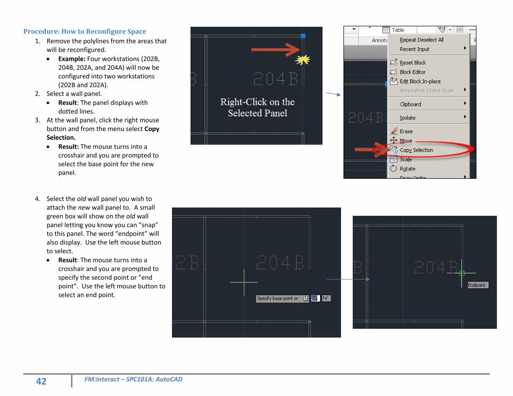
Procedure: How to Reconfigure Space
1. Remove the polylines from the areas that will be reconfigured.
• Example: Four workstations (202B, 204B, 202A, and 204A) will now be configured into two workstations (202B and 202A).
2. Select a wall panel.
• Result: The panel displays with dotted lines.
3. At the wall panel, click the right mouse button and from the menu select Copy Selection.
• Result: The mouse turns into a crosshair and you are prompted to select the base point for the new panel.
4. Select the old wall panel you wish to attach the new wall panel to. A small green box will show on the old wall panel letting you know you can “snap” to this panel. The word “endpoint” will also display. Use the left mouse button to select.
• Result: The mouse turns into a crosshair and you are prompted to specify the second point or “end point”. Use the left mouse button to select an end point.
43 FM:Interact – SPC101A: AutoCAD
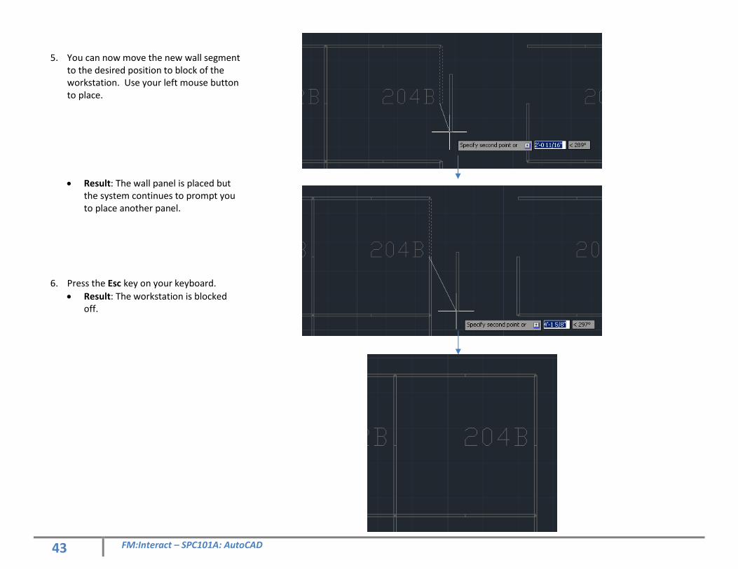
5. You can now move the new wall segment
to the desired position to block of the workstation. Use your left mouse button to place.
• Result: The wall panel is placed but the system continues to prompt you to place another panel.
6. Press the Esc key on your keyboard.
• Result: The workstation is blocked off.
44 FM:Interact – SPC101A: AutoCAD
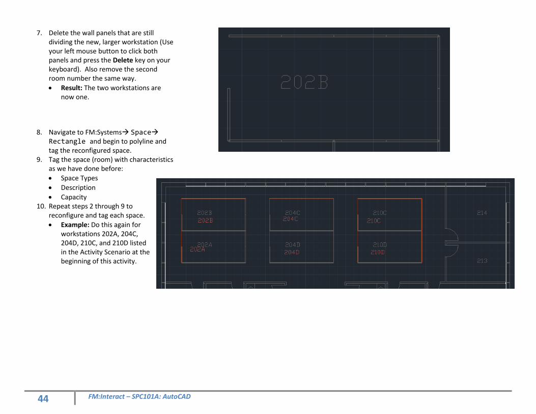
7. Delete the wall panels that are still dividing the new, larger workstation (Use your left mouse button to click both panels and press the Delete key on your keyboard). Also remove the second room number the same way.
• Result: The two workstations are now one.
8. Navigate to FM:Systems Space Rectangle and begin to polyline and tag the reconfigured space.
9. Tag the space (room) with characteristics as we have done before:
• Space Types
• Description
• Capacity 10. Repeat steps 2 through 9 to
reconfigure and tag each space.
• Example: Do this again for workstations 202A, 204C, 204D, 210C, and 210D listed in the Activity Scenario at the beginning of this activity.
45 FM:Interact – SPC101A: AutoCAD
Activity 5, Part 2: Synchronize and
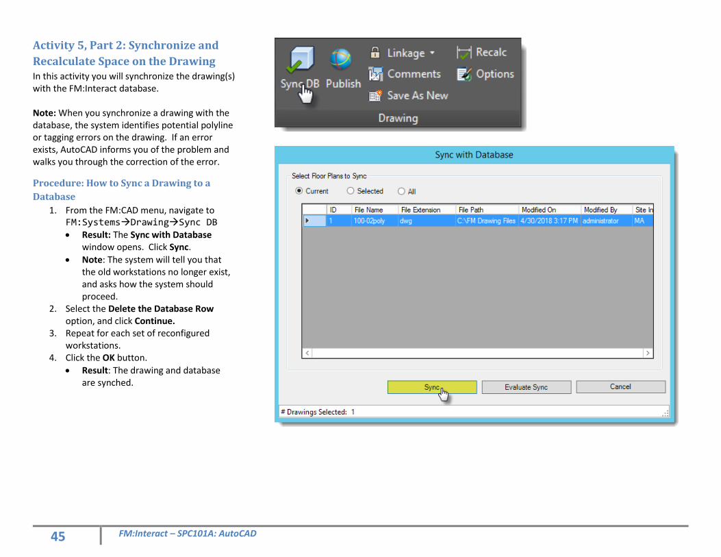
Recalculate Space on the Drawing In this activity you will synchronize the drawing(s) with the FM:Interact database. Note: When you synchronize a drawing with the database, the system identifies potential polyline or tagging errors on the drawing. If an error exists, AutoCAD informs you of the problem and walks you through the correction of the error.
Procedure: How to Sync a Drawing to a
Database
1. From the FM:CAD menu, navigate to FM:SystemsDrawingSync DB • Result: The Sync with Database
window opens. Click Sync.
• Note: The system will tell you that the old workstations no longer exist, and asks how the system should proceed.
2. Select the Delete the Database Row option, and click Continue.
3. Repeat for each set of reconfigured workstations.
4. Click the OK button.
• Result: The drawing and database are synched.
46 FM:Interact – SPC101A: AutoCAD
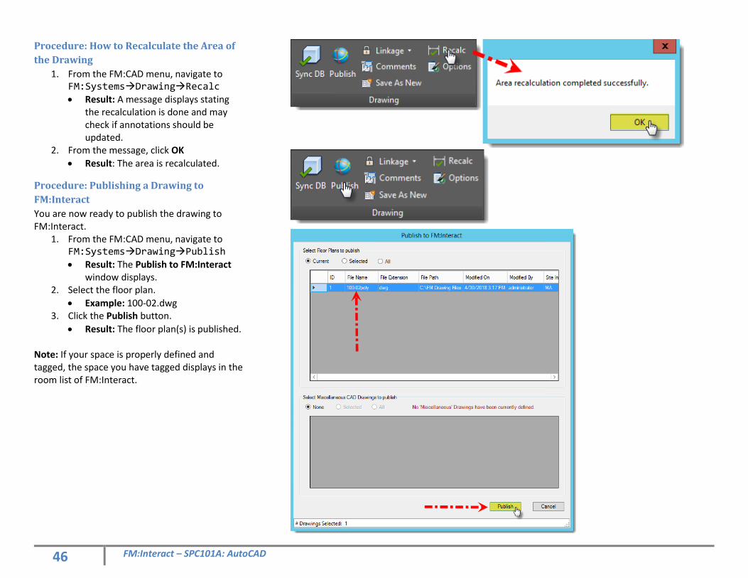
Procedure: How to Recalculate the Area of
the Drawing
1. From the FM:CAD menu, navigate to FM:SystemsDrawingRecalc
• Result: A message displays stating the recalculation is done and may check if annotations should be updated.
2. From the message, click OK
• Result: The area is recalculated.
Procedure: Publishing a Drawing to
FM:Interact
You are now ready to publish the drawing to FM:Interact.
1. From the FM:CAD menu, navigate to FM:SystemsDrawingPublish
• Result: The Publish to FM:Interact window displays.
2. Select the floor plan.
• Example: 100-02.dwg 3. Click the Publish button.
• Result: The floor plan(s) is published. Note: If your space is properly defined and tagged, the space you have tagged displays in the room list of FM:Interact.
47 FM:Interact – SPC101A: AutoCAD
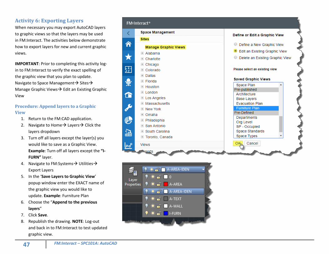
Activity 6: Exporting Layers When necessary you may export AutoCAD layers
to graphic views so that the layers may be used
in FM:Interact. The activities below demonstrate
how to export layers for new and current graphic
views.
IMPORTANT: Prior to completing this activity log-
in to FM:Interact to verify the exact spelling of
the graphic view that you plan to update.
Navigate to Space Management Sites
Manage Graphic Views Edit an Existing Graphic
View
Procedure: Append layers to a Graphic
View
1. Return to the FM:CAD application.
2. Navigate to Home Layers Click the
layers dropdown
3. Turn off all layers except the layer(s) you
would like to save as a Graphic View.
Example: Turn off all layers except the “I-
FURN” layer.
4. Navigate to FM:Systems Utilities
Export Layers
5. In the ‘Save Layers to Graphic View’
popup window enter the EXACT name of
the graphic view you would like to
update. Example: Furniture Plan
6. Choose the “Append to the previous
layers”
7. Click Save.
8. Republish the drawing. NOTE: Log-out
and back in to FM:Interact to test updated
graphic view.
48 FM:Interact – SPC101A: AutoCAD
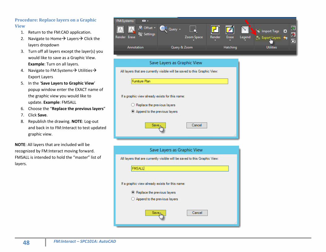
Procedure: Replace layers on a Graphic
View
1. Return to the FM:CAD application.
2. Navigate to Home Layers Click the
layers dropdown
3. Turn off all layers except the layer(s) you
would like to save as a Graphic View.
Example: Turn on all layers.
4. Navigate to FM:Systems Utilities
Export Layers
5. In the ‘Save Layers to Graphic View’
popup window enter the EXACT name of
the graphic view you would like to
update. Example: FMSALL
6. Choose the “Replace the previous layers”
7. Click Save.
8. Republish the drawing. NOTE: Log-out
and back in to FM:Interact to test updated
graphic view.
NOTE: All layers that are included will be
recognized by FM:Interact moving forward.
FMSALL is intended to hold the “master” list of
layers.

49 FM:Interact – SPC101A: AutoCAD
Notes:

50 FM:Interact – SPC101A: AutoCAD
Notes: