Embed Size (px)
Citation preview

© C
OP
YR
IGH
T 2
003,
MU
LTIQ
UIP
IN
C.
OPERATION AND PARTS MANUAL
MIX N' GOMINI CONCRETE MIXERSTEEL DRUM MODELS
MC3SE, MC3S (B&S)PLASTIC DRUM MODELS
MC3PE, MC3P (B&S)
Revision #5 (11/07/2005)
MULTIQUIP INC..... PARTS DEPARTMENT:18910 WILMINGTON AVE. 800-427-1244CARSON, CALIFORNIA 90746 FAX: 800-672-7877310-537-3700 SERVICE DEPARTMENT/TECHNICAL ASSISTANCE:800-421-1244 800-478-1244FAX: 310-537-3927 FAX: 310-631-5032E-mail:[email protected] • www:multiquip.comAtlanta • Boise • Dallas • Houston • NewarkMontreal, Canada • Manchester, UKRio De Janiero, Brazil • Guadalajara, Mexico

MIX N' GO MIXER — OPERATION & PARTS MANUAL — REV. #5 (11/07/05) — PAGE 3
HERE'S HOW TO GET HELPPLEASE HAVE THE MODEL AND SERIAL NUMBERON-HAND WHEN CALLING
PARTS DEPARTMENT800-427-1244 or 310-537-3700FAX: 800-672-7877 or 310-637-3284
SERVICE DEPARTMENT/TECHNICAL ASSISTANCE800-478-1244 or 310-537-3700FAX: 310- 537-4259
WARRANTY DEPARTMENT888-661-4279, or 310-661-4279FAX: 310- 537-1173
MAIN800-421-1244 or 310-537-3700FAX: 310-537-3927
PAGE 4 —MIX N' GO MIXER — OPERATION & PARTS MANUAL — REV. #5 (1/07/05)
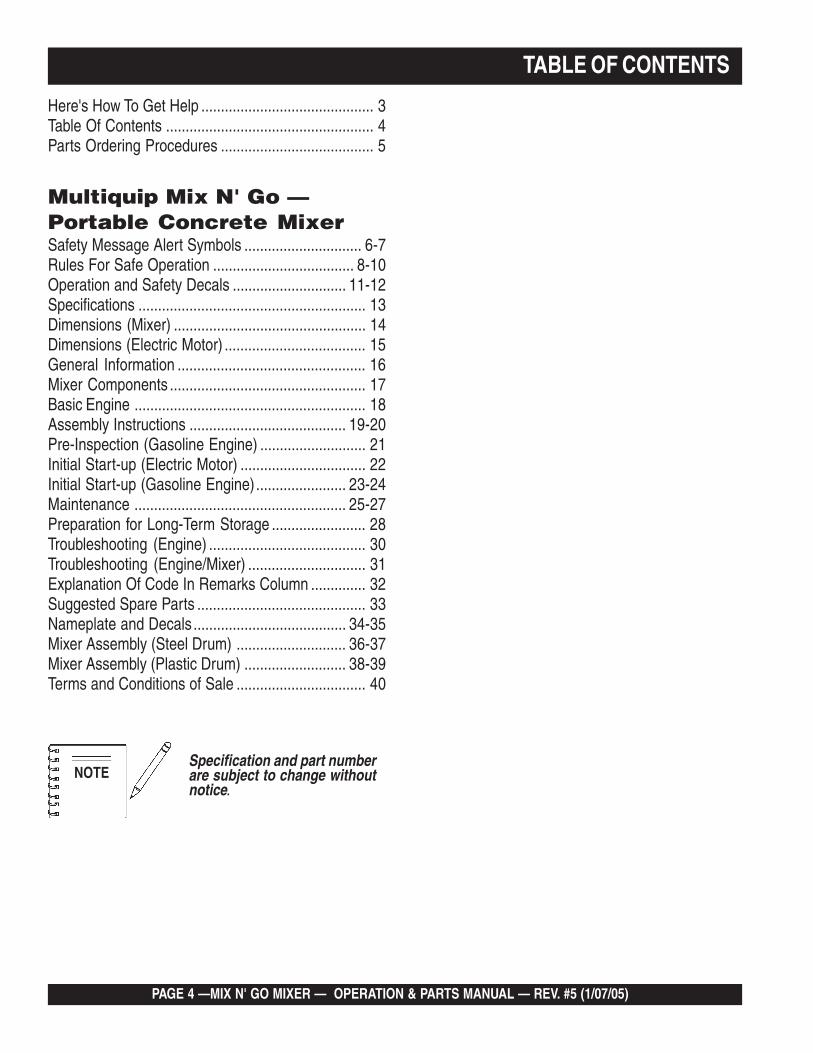
TABLE OF CONTENTS
Here's How To Get Help ............................................ 3Table Of Contents ..................................................... 4Parts Ordering Procedures ....................................... 5
Multiquip Mix N' Go —Portable Concrete MixerSafety Message Alert Symbols .............................. 6-7Rules For Safe Operation .................................... 8-10Operation and Safety Decals ............................. 11-12Specifications .......................................................... 13Dimensions (Mixer) ................................................. 14Dimensions (Electric Motor) .................................... 15General Information ................................................ 16Mixer Components .................................................. 17Basic Engine ........................................................... 18Assembly Instructions ........................................ 19-20Pre-Inspection (Gasoline Engine) ........................... 21Initial Start-up (Electric Motor) ................................ 22Initial Start-up (Gasoline Engine)....................... 23-24Maintenance ...................................................... 25-27Preparation for Long-Term Storage ........................ 28Troubleshooting (Engine) ........................................ 30Troubleshooting (Engine/Mixer) .............................. 31Explanation Of Code In Remarks Column .............. 32Suggested Spare Parts ........................................... 33Nameplate and Decals ....................................... 34-35Mixer Assembly (Steel Drum) ............................ 36-37Mixer Assembly (Plastic Drum) .......................... 38-39Terms and Conditions of Sale ................................. 40
Specification and part numberare subject to change withoutnotice.
NOTE
MIX N' GO MIXER — OPERATION & PARTS MANUAL — REV. #5 (11/07/05) — PAGE 5
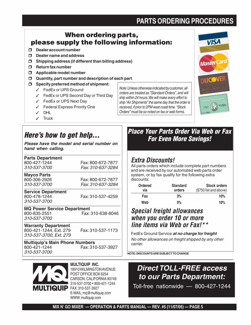
PARTS ORDERING PROCEDURES
When ordering parts,please supply the following information:
❒❒❒❒❒ Dealer account number❒❒❒❒❒ Dealer name and address❒❒❒❒❒ Shipping address (if different than billing address)❒❒❒❒❒ Return fax number❒❒❒❒❒ Applicable model number❒❒❒❒❒ Quantity, part number and description of each part❒❒❒❒❒ Specify preferred method of shipment:
✓ FedEx or UPS Ground✓ FedEx or UPS Second Day or Third Day✓ FedEx or UPS Next Day✓ Federal Express Priority One✓ DHL✓ Truck
Here’s how to get help...Please have the model and serial number onhand when calling.
Parts Department800-427-1244 Fax: 800-672-7877310-537-3700 Fax: 310-637-3284
Mayco Parts800-306-2926 Fax: 800-672-7877310-537-3700 Fax: 310-637-3284
Service Department800-478-1244 Fax: 310-537-4259310-537-3700
MQ Power Service Department800-835-2551 Fax: 310-638-8046310-537-3700
Warranty Department800-421-1244, Ext. 279 Fax: 310-537-1173310-537-3700, Ext. 279
Multiquip’s Main Phone Numbers800-421-1244 Fax: 310-537-3927310-537-3700
Note: Unless otherwise indicated by customer, allorders are treated as “Standard Orders”, and willship within 24 hours. We will make every effort toship “Air Shipments” the same day that the order isreceived, if prior to 2PM west coast time. “StockOrders” must be so noted on fax or web forms.
Extra Discounts!All parts orders which include complete part numbersand are received by our automated web parts ordersystem, or by fax qualify for the following extradiscounts:
Ordered Standard Stock ordersvia orders ($750 list and above)
Fax 3% 10%
Web 5% 10%
Special freight allowanceswhen you order 10 or moreline items via Web or Fax!**FedEx Ground Service at no charge for freightNo other allowances on freight shipped by any othercarrier.
Place Your Parts Order Via Web or FaxFor Even More Savings!
NOTE: DISCOUNTS ARE SUBJECT TO CHANGE
MULTIQUIP INC.18910 WILMINGTON AVENUEPOST OFFICE BOX 6254CARSON, CALIFORNIA 90749310-537-3700 • 800-421-1244FAX: 310-537-3927E-MAIL: [email protected]: multiquip.com
Direct TOLL-FREE accessto our Parts Department:
Toll-free nationwide — 800-427-1244
PAGE 6 —MIX N' GO MIXER — OPERATION & PARTS MANUAL — REV. #5 (1/07/05)
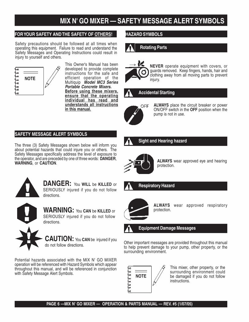
Accidental Starting
ALWAYS place the circuit breaker or powerON/OFF switch in the OFF position when thepump is not in use.
Respiratory Hazard
ALWAYS wear approved respiratoryprotection.
Equipment Damage Messages
Other important messages are provided throughout this manualto help prevent damage to your pump, other property, or thesurrounding environment.
ALWAYS wear approved eye and hearingprotection.
Sight and Hearing hazard
MIX N' GO MIXER — SAFETY MESSAGE ALERT SYMBOLS
Safety precautions should be followed at all times whenoperating this equipment. Failure to read and understand theSafety Messages and Operating Instructions could result ininjury to yourself and others.
FOR YOUR SAFETY AND THE SAFETY OF OTHERS!
This Owner's Manual has beendeveloped to provide completeinstructions for the safe andefficient operation of theMultiquip Model MC3 SeriesPortable Concrete Mixers.Before using these mixers,ensure that the operatingindividual has read andunderstands all instructionsin this manual.
SAFETY MESSAGE ALERT SYMBOLS
The three (3) Safety Messages shown below will inform youabout potential hazards that could injure you or others. TheSafety Messages specifically address the level of exposure tothe operator, and are preceded by one of three words: DANGER,WARNING, or CAUTION.
DANGER: You WILL be KILLED orSERIOUSLY injured if you do not followdirections.
WARNING: You CAN be KILLED orSERIOUSLY injured if you do not followdirections.
CAUTION: You CAN be injured if youdo not follow directions.
HAZARD SYMBOLS
Potential hazards associated with the MIX N' GO MIXERoperation will be referenced with Hazard Symbols which appearthroughout this manual, and will be referenced in conjunctionwith Safety Message Alert Symbols.
Rotating Parts
NEVER operate equipment with covers, orguards removed. Keep fingers, hands, hair andclothing away from all moving parts to preventinjury.NOTE
This mixer, other property, or thesurrounding environment couldbe damaged if you do not followinstructions.
NOTE
MIX N' GO MIXER — OPERATION & PARTS MANUAL — REV. #5 (11/07/05) — PAGE 7
MIX N' GO MIXER — SAFETY MESSAGE ALERT SYMBOLS
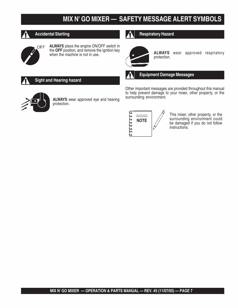
Accidental Starting
ALWAYS place the engine ON/OFF switch inthe OFF position, and remove the ignition keywhen the machine is not in use.
Respiratory Hazard
ALWAYS wear approved respiratoryprotection.
Equipment Damage Messages
Other important messages are provided throughout this manualto help prevent damage to your mixer, other property, or thesurrounding environment.ALWAYS wear approved eye and hearing
protection.
Sight and Hearing hazard
This mixer, other property, or thesurrounding environment couldbe damaged if you do not followinstructions.
NOTE
PAGE 8 —MIX N' GO MIXER — OPERATION & PARTS MANUAL — REV. #5 (1/07/05)
RULES FOR SAFE OPERATION
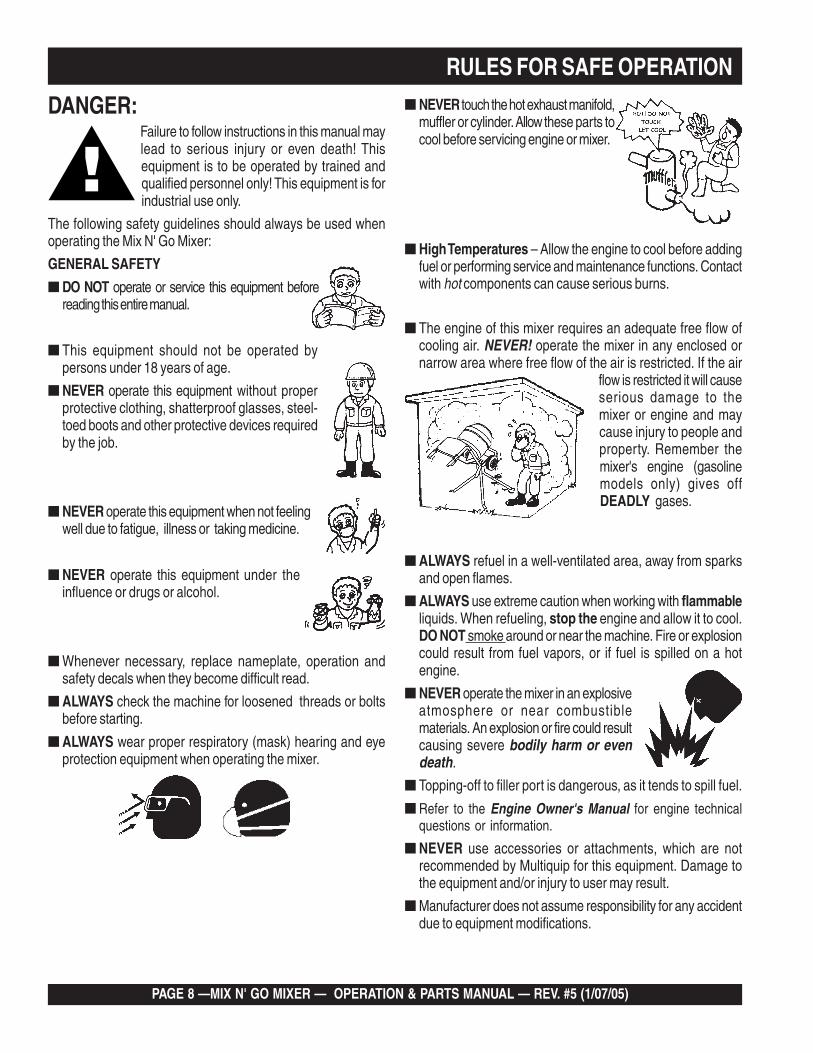
■ ALWAYS refuel in a well-ventilated area, away from sparksand open flames.
■ ALWAYS use extreme caution when working with flammableliquids. When refueling, stop the engine and allow it to cool.DO NOT smoke around or near the machine. Fire or explosioncould result from fuel vapors, or if fuel is spilled on a hotengine.
■ NEVER operate the mixer in an explosiveatmosphere or near combustiblematerials. An explosion or fire could resultcausing severe bodily harm or evendeath.
■ Topping-off to filler port is dangerous, as it tends to spill fuel.
■ Refer to the Engine Owner's Manual for engine technicalquestions or information.
■ NEVER use accessories or attachments, which are notrecommended by Multiquip for this equipment. Damage tothe equipment and/or injury to user may result.
■ Manufacturer does not assume responsibility for any accidentdue to equipment modifications.
■ NEVER touch the hot exhaust manifold,muffler or cylinder. Allow these parts tocool before servicing engine or mixer.
■ The engine of this mixer requires an adequate free flow ofcooling air. NEVER! operate the mixer in any enclosed ornarrow area where free flow of the air is restricted. If the air
flow is restricted it will causeserious damage to themixer or engine and maycause injury to people andproperty. Remember themixer's engine (gasolinemodels only) gives offDEADLY gases.
■ High Temperatures – Allow the engine to cool before addingfuel or performing service and maintenance functions. Contactwith hot components can cause serious burns.
DANGER:Failure to follow instructions in this manual maylead to serious injury or even death! Thisequipment is to be operated by trained andqualified personnel only! This equipment is forindustrial use only.
The following safety guidelines should always be used whenoperating the Mix N' Go Mixer:
GENERAL SAFETY
■ DO NOT operate or service this equipment beforereading this entire manual.
■ This equipment should not be operated bypersons under 18 years of age.
■ NEVER operate this equipment without properprotective clothing, shatterproof glasses, steel-toed boots and other protective devices requiredby the job.
■ NEVER operate this equipment when not feelingwell due to fatigue, illness or taking medicine.
■ NEVER operate this equipment under theinfluence or drugs or alcohol.
■ Whenever necessary, replace nameplate, operation andsafety decals when they become difficult read.
■ ALWAYS check the machine for loosened threads or boltsbefore starting.
■ ALWAYS wear proper respiratory (mask) hearing and eyeprotection equipment when operating the mixer.

MIX N' GO MIXER — OPERATION & PARTS MANUAL — REV. #5 (11/07/05) — PAGE 9
■ High Temperatures – Always stop engine and allow theengine to cool before adding fuel, oil or performing serviceand maintenance functions. Contact with hot components cancause serious burns.
■ NEVER disconnect any "emergency or safety devices".These devices are intended for operator safety. Disconnectionof these devices can cause severe injury, bodily harm or evendeath! Disconnection of any of these devices will void allwarranties.
■ If mixer is equipped with an electric motor, operate only at120 VAC, 60 Hz.
■ Make sure the OFF/ON power switch is always in the OFFposition before inserting the mixer's power plug into an ACreceptacle (electric model only).
Maintenance Safety■ NEVER lubricate components or attempt service on a running
machine.
■ ALWAYS allow the machine a proper amount of time to coolbefore servicing.
■ Keep the machinery in proper running condition.
■ Fix damage to the machine immediately and always replacebroken parts, or missing decals.
■ Dispose of hazardous waste properly. Examples of potentiallyhazardous waste are used motor oil, fuel and fuel filters.
■ DO NOT use food or plastic containers to dispose ofhazardous waste.
■ DO NOT pour waste, oil or fuel directly onto the ground,down a drain or into any water source.
RULES FOR SAFE OPERATION
■ NEVER Run engine without air cleaner. Severe enginedamage may occur.
■ ALWAYS read, understand, and follow procedures inOperator’s Manual before attempting to operate equipment.
■ ALWAYS be sure the operator is familiar with proper safetyprecautions and operations techniques before using roller.
■ ALWAYS store equipment properly when it is not being used.Equipment should be stored in a clean, dry location out of thereach of children.
■ NEVER leave the mixer unattended, turn off engine or electricmotor when unattended.
■ CAUTION must always be observed while servicing this mixer.Rotating parts can cause injury if contacted.
■ Unauthorized equipment modifications will void allwarranties.
■ Ensure that any trailing cable is protected against damageand not liable to be tripped over or trapped underneath themixer.
■ Ensure any extention cables must be no longer than 30 meters(100 feet) in length and that the wire section is 2.5 mm 2.
■ DO NOT allow extension cord to come into contact with wateror fluids.
■ DO NOT spray water onto electric motor.
■ DO NOT expose power tools to rain or wet conditions.
■ This mixer is intended for the production of concrete, mortarand plaster. Mixer must be used only for its intended purpose.
■ This mixer is not suitable for the mixing of flammable orexplosive substances.
■ NEVER operate the mixer in an explosive atmosphere.
■ Before starting the mixer, check that all guards are in positionand correctly fitted.
■ DO NOT tip mixer onto drum mouth when the motor is running.
■ Keep area around the mixer clear of obstructions whichcould cause persons to fall onto moving parts.
■ ALWAYS ensure mixer is on level ground before mixing.
■ Become familiar with the controls of the machine beforeoperating.
■ ALWAYS replace any worn or damaged warning decals.
■ Ensure the drum is rotating while filling and emptying thedrum.
■ ALWAYS disconnect AC power plug from power sourcebefore moving mixer (electric model only).
PAGE 10 —MIX N' GO MIXER — OPERATION & PARTS MANUAL — REV. #5 (1/07/05)
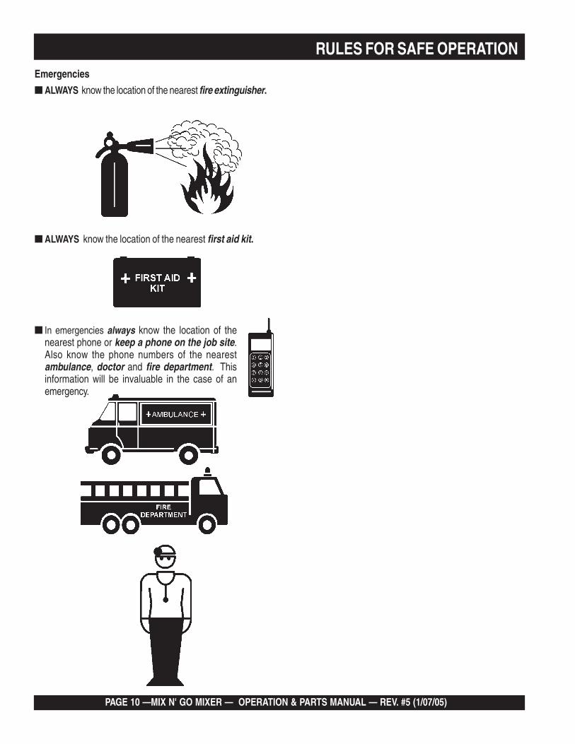
Emergencies
■ ALWAYS know the location of the nearest fire extinguisher.
■ ALWAYS know the location of the nearest first aid kit.
■ In emergencies always know the location of thenearest phone or keep a phone on the job site.Also know the phone numbers of the nearestambulance, doctor and fire department. Thisinformation will be invaluable in the case of anemergency.
RULES FOR SAFE OPERATION
MIX N' GO MIXER — OPERATION & PARTS MANUAL — REV. #5 (11/07/05) — PAGE 11
OPERATION AND SAFETY DECALS
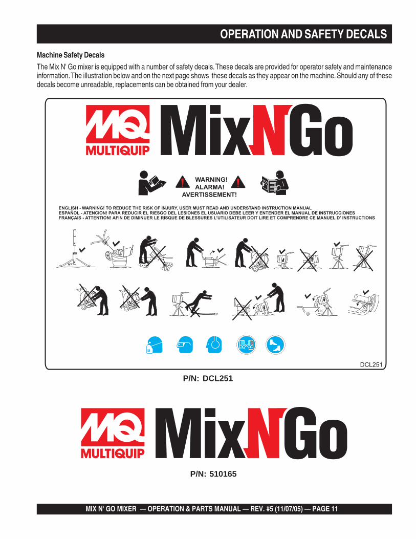
Machine Safety Decals
The Mix N' Go mixer is equipped with a number of safety decals. These decals are provided for operator safety and maintenanceinformation. The illustration below and on the next page shows these decals as they appear on the machine. Should any of thesedecals become unreadable, replacements can be obtained from your dealer.
WARNING!ALARMA!
AVERTISSEMENT!
ENGLISH - WARNING! TO REDUCE THE RISK OF INJURY, USER MUST READ AND UNDERSTAND INSTRUCTION MANUALESPAÑOL - ATENCION! PARA REDUCIR EL RIESGO DEL LESIONES EL USUARIO DEBE LEER Y ENTENDER EL MANUAL DE INSTRUCCIONESFRANÇAIS - ATTENTION! AFIN DE DIMINUER LE RISQUE DE BLESSURES L’UTILISATEUR DOIT LIRE ET COMPRENDRE CE MANUEL D’ INSTRUCTIONS
DCL251
P/N: DCL251
P/N: 510165
PAGE 12 —MIX N' GO MIXER — OPERATION & PARTS MANUAL — REV. #5 (1/07/05)
OPERATION AND SAFETY DECALS
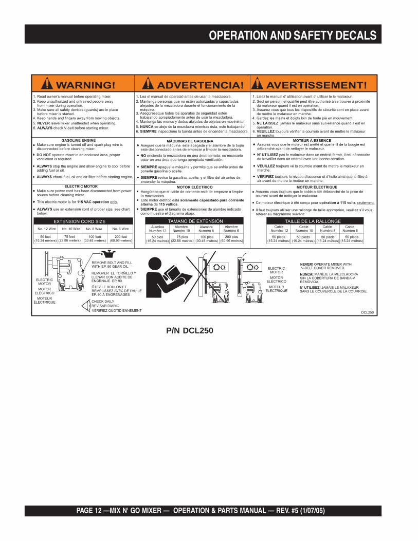
6. check V-belt before starting mixer.ALWAYS
1. Read owner’s manual before operating mixer.
ELECTRIC MOTORMake sure power cord has been disconnected from powersource before cleaning mixer.
use an extension cord of proper size, see chartbelow:ALWAYS
50 feet(15.24 meters)
No. 12 Wire No. 10 Wire No. 8 Wire No. 6 Wire
100 feet(30.48 meters)
75 feet(22.86 meters)
200 feet(60.96 meters)
EXTENSION CORD SIZE
This electric motor is for .115 VAC operation only
GASOLINE ENGINEMake sure engine is turned off and spark plug wire isdisconnected before cleaning mixer.
operate mixer in an enclosed area, properventilation is required.DO NOT
stop the engine and allow engine to cool beforeadding fuel or oil.ALWAYS
check fuel, oil and air filter before starting engine.ALWAYS
MOTEUR ÉLECTRIQUEAssures vous toujours que le cable a été débranché de la prise decourant avant de nettoyer le malaxeur.
Il faut toujours utiliser une rallonge de taille appropriée, veuillez s’il vousréférer au diagramme suivant:
Ce moteur électrique à été conçu pour opération à 115 volts seulement.
MOTEUR À ESSENCEAssurez vous que le moteur est arrêté et que le fil de la bougie estdébranché avant de nettoyer le malaxeur.
pas le malaxeur dans un endroit fermé, il est nécessairede travailler dans un endroit avec une bonne aération.N’ UTILISEZ
toujours vé la courroie avant de mettre le malaxeur enmarche.VEUILLEZ
toujours le niveau d’essence et d’huile ainsi que le filtre àair avant de mettre le moteur en marche.VÉRIFIEZ
REMOVE BOLT AND FILLWITH EP. 90 GEAR OIL
ELECTRICMOTOR
CHECK DAILY
NEVER! OPERATE MIXER WITHV-BELT COVER REMOVED.
MOTORELÉCTRICO
MOTEURÉLECTRIQUE
REVISAR DIARIO
ÔTEZ LE BOULON ETREMPLISSEZ AVEC DE I’HUILEEP. 90 À ENGRENAGES
2. Keep unauthorized and untrained people awayfrom mixer during operation.
3. Make sure all safety devices (guards) are in placebefore mixer is started.
4. Keep hands and fingers away from moving objects.5. leave mixer unattended when operating.NEVER
6. inspeccione la banda antes de encender la mezcladora.SIEMPRE
1. Lea el manual de operació antes de usar la mezcladora.2. Mantenga personas que no estén autorizadas o capacitadas
alejades de la mezcladora durante el funcionamiento de lamáquina.
3. Asegúreseque todos los aparatos de seguridad esténtrabajando apropiadamente antes de usar la mezcladora.
4. Mantenga las monos y dedos alejados de objetos en moviminto.5. se aleje de la mezclaora mientras ésta, este trabajando!NUNCA
6. toujours vérifier la courroie avant de mettre le malaxeuren marche.VEUILLEZ
1. Lisez le manual d’ utilisation avant d’ utiliser le le malaxeur.2. Seul un personnel qualifié peut être authorisé à se trouver à proximité
du malaxeur quand il est en opération.3. Assurez vous que tous les dispositifs de sécurité sont en place avant
de mettre le malaxeur en marche.4. Gardez les mains et doigts loin de toute piè en mouvement.5. jamais le malaxeur sans surveillance quand il est en
opération.NE LAISSEZ
WARNING! ADVERTENCIA! AVERTISSEMENT!
NUNCA! MANEJE LA MEZCLADORASIN LA COBERTURA DE BANDA-VREMOVIDA.
N’ UTILISEZ! JAMAIS LE MALAXEURSANS LE COUVERCLE DE LA COURROIE.
DCL250
MOTOR ELÉCTRICOAsegúrese que el cable de corriente esté de empezar a limpiarla mezcladora.
use el tamaño de extensiones de alambre indicadocomo muestra el diagrama abajo:SIEMPRE
Este motor elétrico estáde .
solamente capacitado para corrientealterna 115 voltios
MÁQUINAS DE GASOLINAAsegure que la máquina este apagada y el alambre de la bujíaeste desconectado antes de empezar a limpiar la mezcladora.
encienda la mezcladora en una área cerrada; es necesarioestar en una área que tenga apropiada ventilación.NO
apague la máquina y permita que se enfrie antes deponerle gasolina o aceite.SIEMPRE
revise la gasolina, aceite, y el filtro del air antes deencender la máquina.SIEMPRE
50 pieds(15.24 métres)
CableNuméro 12
TAILLE DE LA RALLONGECable
Numéro 10Cable
Numéro 8Cable
Numéro 6
50 pieds(15.24 métres)
50 pieds(15.24 métres)
50 pieds(15.24 métres)
50 pies(15.24 metros)
AlambreNuméro 12
100 pies(30.48 metros)
75 pies(22.86 metros)
200 pies(60.96 metros)
TAMAÑO DE EXTENSIÓNAlambre
Numéro 10Alambre
Numéro 8Alambre
Numéro 6
VÉRIFIEZ QUOTIDIENNEMENT
ELECTRICMOTOR
MOTORELÉCTRICO
MOTEURÉLECTRIQUE
REMOVER EL TORÑILLO YLLENAR CON ACEITE DEENGRNAJE EP. 90
P/N DCL250
MIX N' GO MIXER — OPERATION & PARTS MANUAL — REV. #5 (11/07/05) — PAGE 13
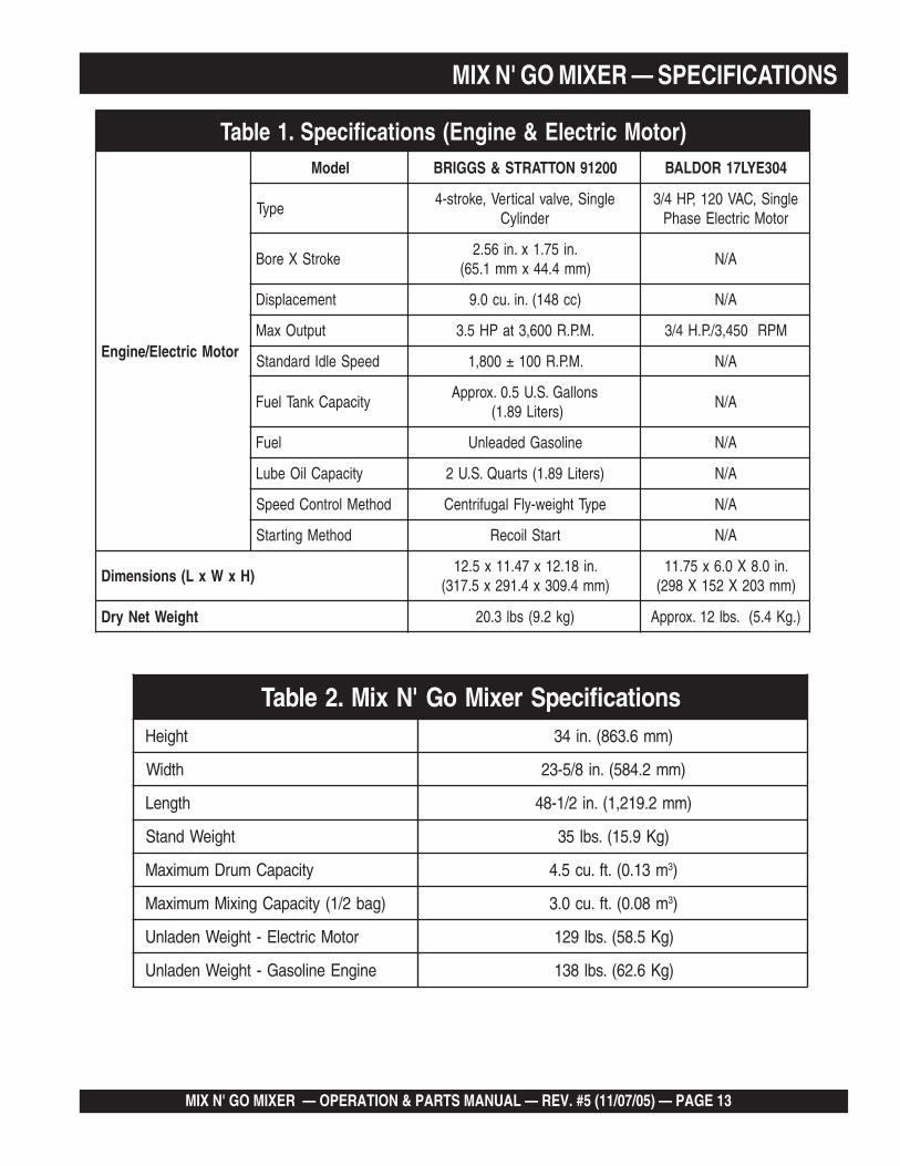
MIX N' GO MIXER — SPECIFICATIONS
snoitacificepSrexiMoG'NxiM.2elbaTthgieH )mm6.368(.ni43
htdiW )mm2.485(.ni8/5-32
htgneL )mm2.912,1(.ni2/1-84
thgieWdnatS )gK9.51(.sbl53
yticapaCmurDmumixaM m31.0(.tf.uc5.4 3)
)gab2/1(yticapaCgnixiMmumixaM m80.0(.tf.uc0.3 3)
rotoMcirtcelE-thgieWnedalnU )gK5.85(.sbl921
enignEenilosaG-thgieWnedalnU )gK6.26(.sbl831
)rotoMcirtcelE&enignE(snoitacificepS.1elbaT
rotoMcirtcelE/enignE
ledoM 00219NOTTARTS&SGGIRB 403EYL71RODLAB
epyTelgniS,evlavlacitreV,ekorts-4
rednilyCelgniS,CAV021,PH4/3
rotoMcirtcelEesahP
ekortSXeroB.ni57.1x.ni65.2
)mm4.44xmm1.56(A/N
tnemecalpsiD )cc841(.ni.uc0.9 A/N
tuptuOxaM .M.P.R006,3taPH5.3 MPR054,3/.P.H4/3
deepSeldIdradnatS .M.P.R001±008,1 A/N
yticapaCknaTleuFsnollaG.S.U5.0.xorppA
)sretiL98.1(A/N
leuF enilosaGdedaelnU A/N
yticapaCliOebuL )sretiL98.1(strauQ.S.U2 A/N
dohteMlortnoCdeepS epyTthgiew-ylFlagufirtneC A/N
dohteMgnitratS tratSlioceR A/N
)HxWxL(snoisnemiD.ni81.21x74.11x5.21
)mm4.903x4.192x5.713(.ni0.8X0.6x57.11)mm302X251X892(
thgieWteNyrD )gk2.9(sbl3.02 ).gK4.5(.sbl21.xorppA
PAGE 14 —MIX N' GO MIXER — OPERATION & PARTS MANUAL — REV. #5 (1/07/05)
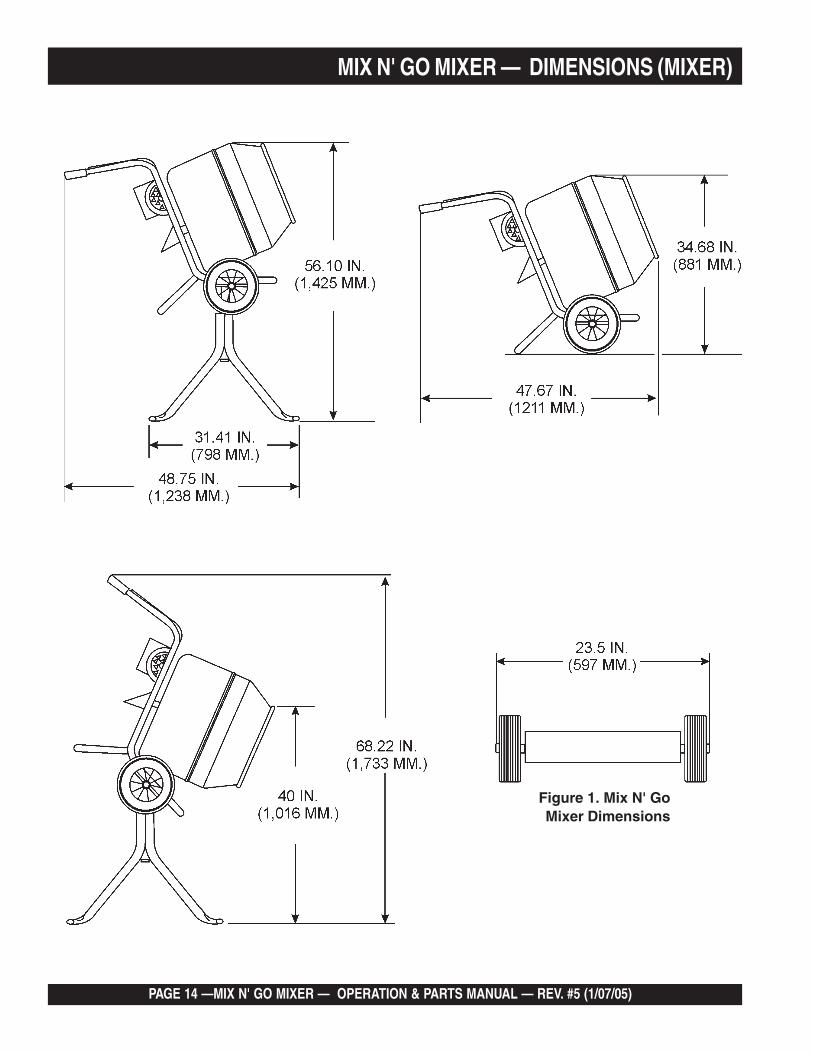
MIX N' GO MIXER — DIMENSIONS (MIXER)
Figure 1. Mix N' Go Mixer Dimensions
MIX N' GO MIXER — OPERATION & PARTS MANUAL — REV. #5 (11/07/05) — PAGE 15
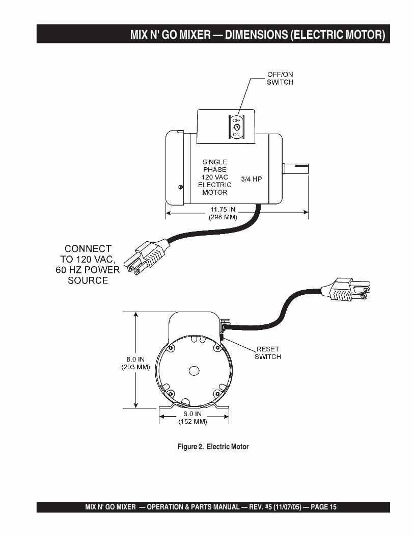
MIX N' GO MIXER — DIMENSIONS (ELECTRIC MOTOR)
Figure 2. Electric Motor
PAGE 16 —MIX N' GO MIXER — OPERATION & PARTS MANUAL — REV. #5 (1/07/05)
MIX N' GO MIXER — GENERAL INFORMATIONAPPLICATION
This mixer is only intended for the production of concreteand mortar. The mixer must be used for its intendedpurposes and is not suitable for the mixing of flammable orexplosive substances. The mixer must not be used in anexplosive atmosphere.
POWER PLANTS
This portable mixer is powered by either a Briggs and Stratton4-stroke, verticle valve, single cylinder, gasoline engine ratedat 3.5 hp @3,600 rpm. or a 0.75 hp electric motor.
DRUM ASSEMBLY
The drum is instantly removable by unscrewing counter-clockwise. When inserting drum onto gearbox shaft, make surethat drum is fully screwed onto shoulder or threads may bedamaged. Use extreme care when screwing on the drum,spinning drum onto the gearbox shaft too fast may damagegearbox.
ELECTRICAL
If mixer is equipped with an electric motor, make sure thatthe power being supplied to the motor corresponds to thevoltage rating label on the motor. Supplying the wrong voltageto the electric motor will cause severe electrical damage tothe motor.
Always make sure that OFF/ON switch on the electric motoris in the OFF position before applying power.
It is strongly recommended that when plugging in themixer's power cord into a receptacle, that a G.F.C.I. (GroundFault Current Interrupter) receptacle be used.
EXTENSION CABLES
The extension cable should be a 3-wire configuration thatincludes a ground wire that conforms to UL code. The wirecross section must be a minimum of 2.5 mm2 . Choose anextension cord of adequate current carrying as Reference inTable 5. Remember distance affects the wire size of theextension cable.
Ensure that the extension cable is carefully laid out avoid-ing wet areas, sharp edges and locations where vehiclesmight run over it. Avoid allowing the extension cable to betrapped underneath the mixer.
Unroll the extension cable fully or it will overheat and couldcatch fire. Make sure that all extension cable connectionsare dry and safe. Replace any defective or badly worn ex-tension cable immediately.
PORTABLE GENERATORS
When using a portable generator it must have a minimumoutput of 2.5 kw and be continuous rated.
GEARBOX
The gearbox oil level has been preset at the factory prior toshipping. Before inspecting the gearbox oil level (Figures 30and 31), make sure the gearbox is cold before removing thefiller plug. Fill up with EP90. or similar gear oil.
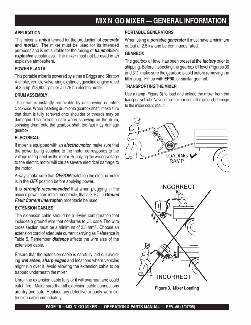
TRANSPORTING THE MIXER
Use a ramp (Figure 3) to load and unload the mixer from thetransport vehicle. Never drop the mixer onto the ground; damageto the mixer could result.
Figure 3. Mixer Loading
MIX N' GO MIXER — OPERATION & PARTS MANUAL — REV. #5 (11/07/05) — PAGE 17
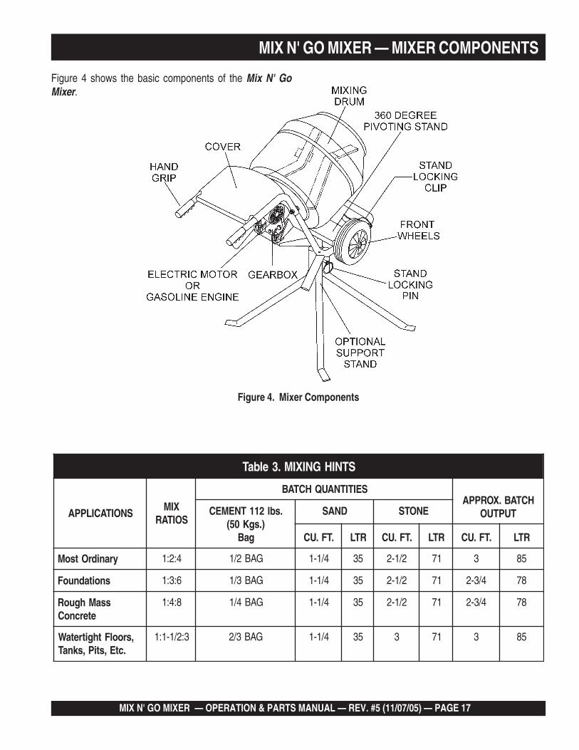
MIX N' GO MIXER — MIXER COMPONENTS
Figure 4. Mixer Components
STNIHGNIXIM.3elbaT
SNOITACILPPAXIM
SOITAR
SEITITNAUQHCTABHCTAB.XORPPA
TUPTUO.sbl211TNEMEC).sgK05(
gaB
DNAS ENOTS
.TF.UC RTL .TF.UC RTL .TF.UC RTL
yranidrOtsoM 4:2:1 GAB2/1 4/1-1 53 2/1-2 17 3 58
snoitadnuoF 6:3:1 GAB3/1 4/1-1 53 2/1-2 17 4/3-2 87
ssaMhguoRetercnoC
8:4:1 GAB4/1 4/1-1 53 2/1-2 17 4/3-2 87
,sroolFthgitretaW.ctE,stiP,sknaT
3:2/1-1:1 GAB3/2 4/1-1 53 3 17 3 58
Figure 4 shows the basic components of the Mix N' GoMixer.
PAGE 18 —MIX N' GO MIXER — OPERATION & PARTS MANUAL — REV. #5 (1/07/05)
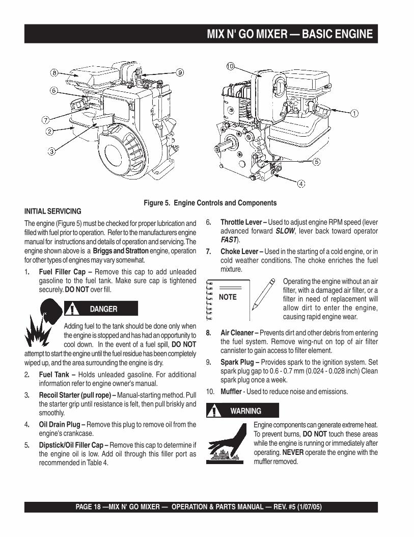
Figure 5. Engine Controls and ComponentsINITIAL SERVICING
The engine (Figure 5) must be checked for proper lubrication andfilled with fuel prior to operation. Refer to the manufacturers enginemanual for instructions and details of operation and servicing. Theengine shown above is a Briggs and Stratton engine, operationfor other types of engines may vary somewhat.
1. Fuel Filler Cap – Remove this cap to add unleadedgasoline to the fuel tank. Make sure cap is tightenedsecurely. DO NOT over fill.
6. Throttle Lever – Used to adjust engine RPM speed (leveradvanced forward SLOW, lever back toward operatorFAST).
7. Choke Lever – Used in the starting of a cold engine, or incold weather conditions. The choke enriches the fuelmixture.
DANGER
MIX N' GO MIXER — BASIC ENGINE
Adding fuel to the tank should be done only whenthe engine is stopped and has had an opportunity tocool down. In the event of a fuel spill, DO NOT
attempt to start the engine until the fuel residue has been completelywiped up, and the area surrounding the engine is dry.
2. Fuel Tank – Holds unleaded gasoline. For additionalinformation refer to engine owner's manual.
3. Recoil Starter (pull rope) – Manual-starting method. Pullthe starter grip until resistance is felt, then pull briskly andsmoothly.
4. Oil Drain Plug – Remove this plug to remove oil from theengine's crankcase.
5. Dipstick/Oil Filler Cap – Remove this cap to determine ifthe engine oil is low. Add oil through this filler port asrecommended in Table 4.
WARNING
Engine components can generate extreme heat.To prevent burns, DO NOT touch these areaswhile the engine is running or immediately afteroperating. NEVER operate the engine with themuffler removed.
Operating the engine without an airfilter, with a damaged air filter, or afilter in need of replacement willallow dirt to enter the engine,causing rapid engine wear.
NOTE
8. Air Cleaner – Prevents dirt and other debris from enteringthe fuel system. Remove wing-nut on top of air filtercannister to gain access to filter element.
9. Spark Plug – Provides spark to the ignition system. Setspark plug gap to 0.6 - 0.7 mm (0.024 - 0.028 inch) Cleanspark plug once a week.
10. Muffler - Used to reduce noise and emissions.
MIX N' GO MIXER — OPERATION & PARTS MANUAL — REV. #5 (11/07/05) — PAGE 19
MIX N' GO MIXER — ASSEMBLY INSTRUCTIONS
Assembly
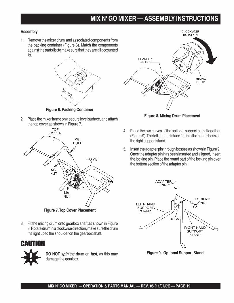
1. Remove the mixer drum and associated components fromthe packing container (Figure 6). Match the componentsagainst the parts list to make sure that they are all accountedfor.
Figure 6. Packing Container
4. Place the two halves of the optional support stand together(Figure 9). The left support stand fits into the center boss onthe right support stand.
5. Insert the adapter pin through bosses as shown in Figure 9.Once the adapter pin has been inserted and aligned, insertthe locking pin. Place the round part of the locking pin overthe bottom section of the adapter pin.
2. Place the mixer frame on a secure level surface, and attachthe top cover as shown in Figure 7.
3. Fit the mixing drum onto gearbox shaft as shown in Figure8. Rotate drum in a clockwise direction, make sure the drumfits right up to the shoulder on the gearbox shaft.
Figure 7. Top Cover Placement
Figure 8. Mixing Drum Placement
Figure 9. Optional Support StandDO NOT spin the drum on fast, as this maydamage the gearbox.
CAUTIONCAUTIONCAUTIONCAUTIONCAUTION
PAGE 20 —MIX N' GO MIXER — OPERATION & PARTS MANUAL — REV. #5 (1/07/05)
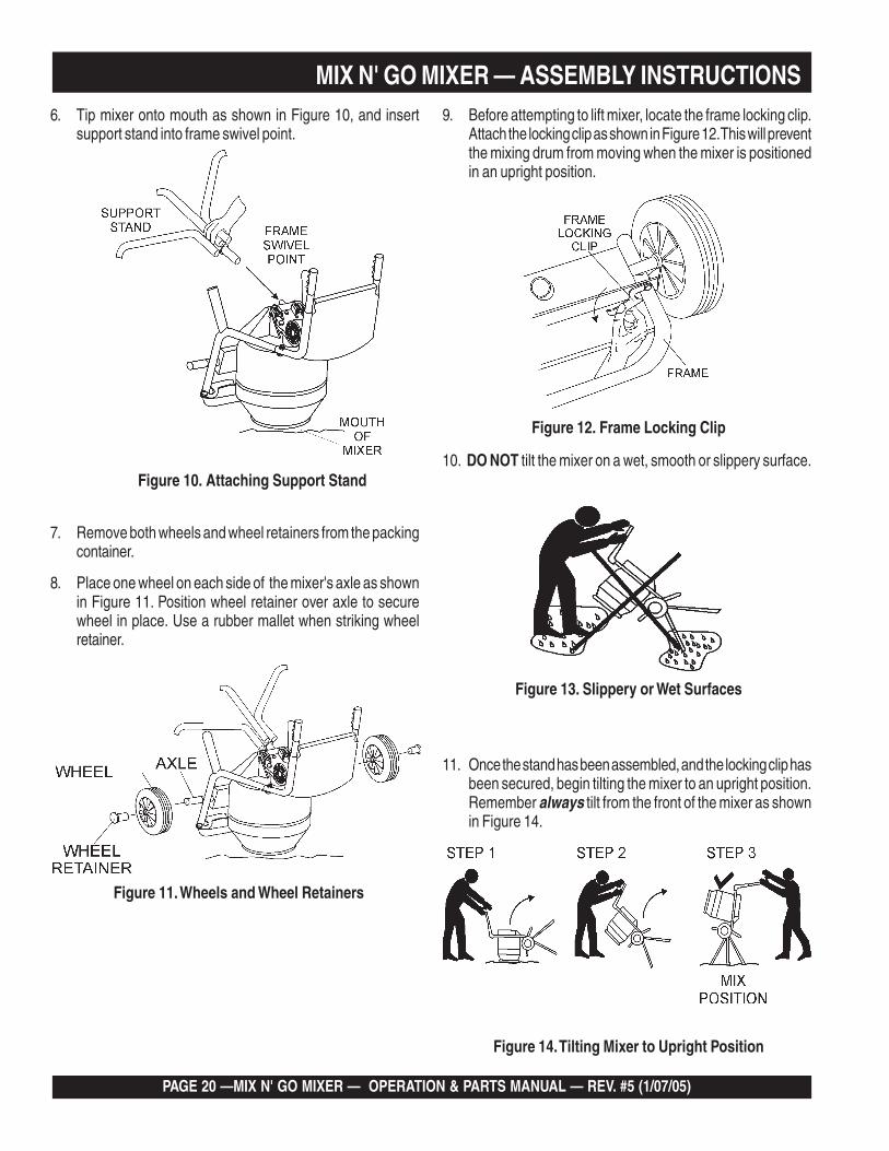
6. Tip mixer onto mouth as shown in Figure 10, and insertsupport stand into frame swivel point.
9. Before attempting to lift mixer, locate the frame locking clip.Attach the locking clip as shown in Figure 12. This will preventthe mixing drum from moving when the mixer is positionedin an upright position.
Figure 12. Frame Locking Clip
Figure 10. Attaching Support Stand10. DO NOT tilt the mixer on a wet, smooth or slippery surface.
Figure 13. Slippery or Wet Surfaces
11. Once the stand has been assembled, and the locking clip hasbeen secured, begin tilting the mixer to an upright position.Remember always tilt from the front of the mixer as shownin Figure 14.
MIX N' GO MIXER — ASSEMBLY INSTRUCTIONS
7. Remove both wheels and wheel retainers from the packingcontainer.
8. Place one wheel on each side of the mixer's axle as shownin Figure 11. Position wheel retainer over axle to securewheel in place. Use a rubber mallet when striking wheelretainer.
Figure 11. Wheels and Wheel Retainers
Figure 14. Tilting Mixer to Upright Position
MIX N' GO MIXER — OPERATION & PARTS MANUAL — REV. #5 (11/07/05) — PAGE 21
MIX N' GO MIXER — PRE-INSPECTION (GASOLINE ENGINE)
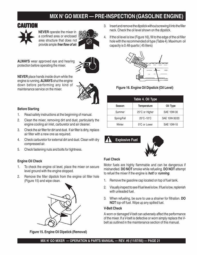
Figure 15. Engine Oil Dipstick (Removal)
3. Insert and remove the dipstick without screwing it into the fillerneck. Check the oil level shown on the dipstick.
4. If the oil level is low (Figure 16), fill to the edge of the oil fillerhole with the recommended oil type (Table 4). Maximum oilcapacity is 0.48 quarts (.45 liters)
Figure 16. Engine Oil Dipstick (Oil Level)
Before Starting
1. Read safety instructions at the beginning of manual.
2. Clean the mixer, removing dirt and dust, particularly theengine cooling air inlet, carburetor and air cleaner.
3. Check the air filter for dirt and dust. If air filter is dirty, replaceair filter with a new one as required.
4. Check carburetor for external dirt and dust. Clean with drycompressed air.
5. Check fastening nuts and bolts for tightness.
Engine Oil Check
1. To check the engine oil level, place the mixer on securelevel ground with the engine stopped.
2. Remove the filler dipstick from the engine oil filler hole(Figure 15) and wipe clean.
CAUTIONCAUTIONCAUTIONCAUTIONCAUTIONNEVER operate the mixer ina confined area or enclosedarea structure that does notprovide ample free flow of air.
ALWAYS wear approved eye and hearingprotection before operating the mixer.
NEVER place hands inside drum while theengine is running. ALWAYS shut the enginedown before performing any kind ofmaintenance service on the mixer.
Fuel Check
Motor fuels are highly flammable and can be dangerous ifmishandled. DO NOT smoke while refueling. DO NOT attemptto refuel the mixer if the engine is hot! or running.
1. Remove the gasoline cap located on top of fuel tank.
2. Visually inspect to see if fuel level is low. If fuel is low, replenishwith unleaded fuel.
3. When refueling, be sure to use a strainer for filtration. DONOT top-off fuel. Wipe up any spilled fuel.
V-Belt Check
A worn or damaged V-belt can adversely affect the performanceof the mixer. If a V-belt is defective or worn simply replace the V-belt as outlined in the maintenance section of this manual.
Explosive Fuel
epyTliO.4elbaT
nosaeS erutarepmeT epyTliO
remmuS rehgiHroC°52 03-W01EAS
llaF/gnirpS C°01~C°52 02/03-W01EAS
retniW rewoLroC°0 01-W01EAS
PAGE 22 —MIX N' GO MIXER — OPERATION & PARTS MANUAL — REV. #5 (1/07/05)
MIX N' GO MIXER — INITIAL START-UP (ELECTRIC MOTOR)
CAUTION:CAUTION:CAUTION:CAUTION:CAUTION:DO NOT attempt to operate the mixer untilthe Safety, General Information andInspection sections have been read andunderstood.
Initial Start-up Instructions (Electric Motor)
Starting
1. Before starting, make sure mixer is positioned on a secureflat surface to prevent tipping.
2. Use an extension cord (see Table 5) of adequate currentcarrying capacity, insert the electric motor's power plug intoone end of the extension cord.
3. NEVER! use a worn or frayed extension cord.
4. NEVER! operate mixer with V-belt cover removed.
5. Plug the other end of the extension cord into a 120 VACG.F.C.I. protected receptacle. Remember the power require-ments for this electric motor is 120 VAC, 60 Hz. The use ofany other input voltage will severely damage the motor.
DANGERDANGERDANGERDANGERDANGERNEVER! touch the power cord (Figure 17)with wet hands or while standing in waterwhen it is connected to a power source. Thepossibly exists of electrical shock(electrocution) even death. NEVER! spray
water directly on the electric motor.
POWERCORD
(POWER ON)
WETHANDS
Figure 17. Extension Cord (Wet Hands)
WARNING:WARNING:WARNING:WARNING:WARNING:ALWAYS read the label on the electric motorbefore applying power. The label will indicate theproper power requirements for the motor.Remember the use of any other input voltage willseverely damage the motor.
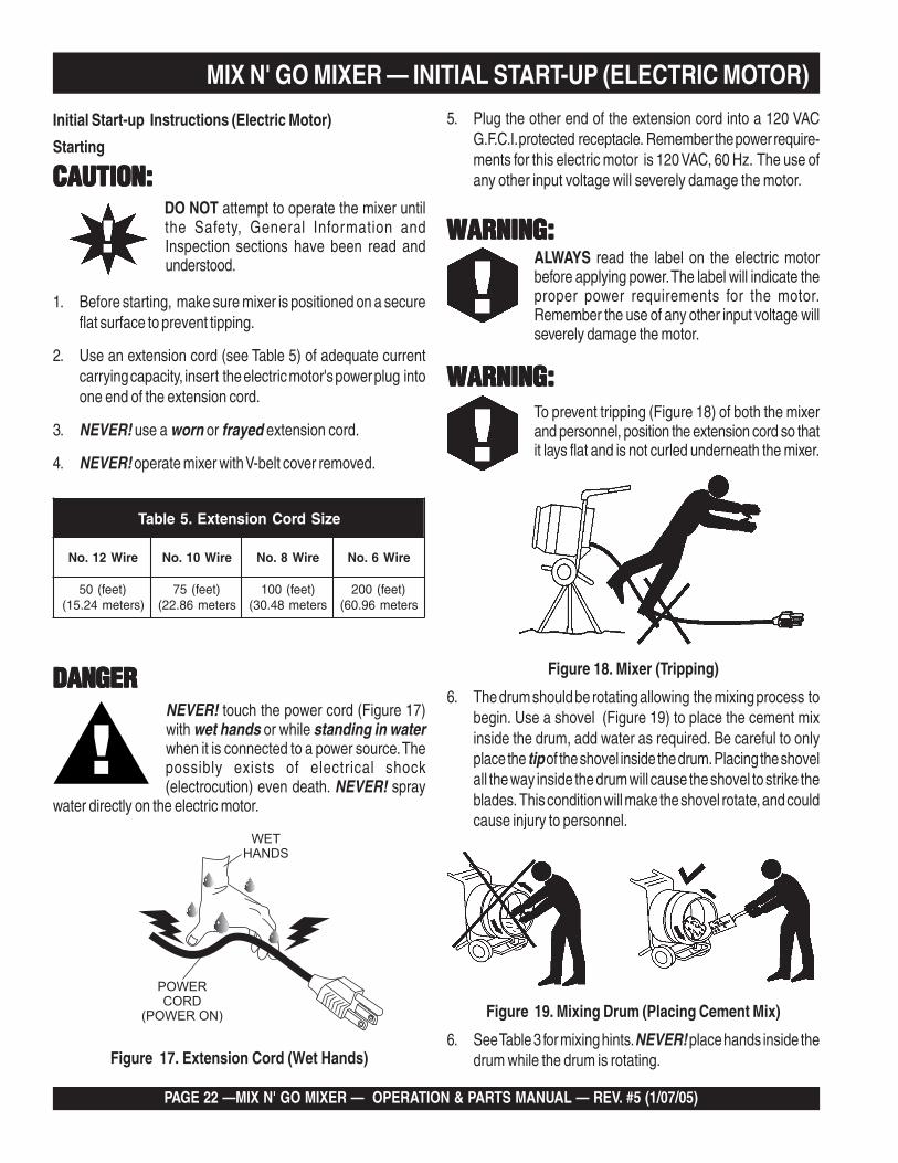
WARNING:WARNING:WARNING:WARNING:WARNING:To prevent tripping (Figure 18) of both the mixerand personnel, position the extension cord so thatit lays flat and is not curled underneath the mixer.
Figure 18. Mixer (Tripping)
6. The drum should be rotating allowing the mixing process tobegin. Use a shovel (Figure 19) to place the cement mixinside the drum, add water as required. Be careful to onlyplace the tip of the shovel inside the drum. Placing the shovelall the way inside the drum will cause the shovel to strike theblades. This condition will make the shovel rotate, and couldcause injury to personnel.
Figure 19. Mixing Drum (Placing Cement Mix)
6. See Table 3 for mixing hints. NEVER! place hands inside thedrum while the drum is rotating.
eziSdroCnoisnetxE.5elbaT
eriW21.oN eriW01.oN eriW8.oN eriW6.oN
)teef(05)sretem42.51(
)teef(57sretem68.22(
)teef(001sretem84.03(
)teef(002sretem69.06(
MIX N' GO MIXER — OPERATION & PARTS MANUAL — REV. #5 (11/07/05) — PAGE 23
MIX N' GO MIXER — INITIAL START-UP (GASOLINE ENGINE)
Starting the Engine (BRIGGS & STRATTON)
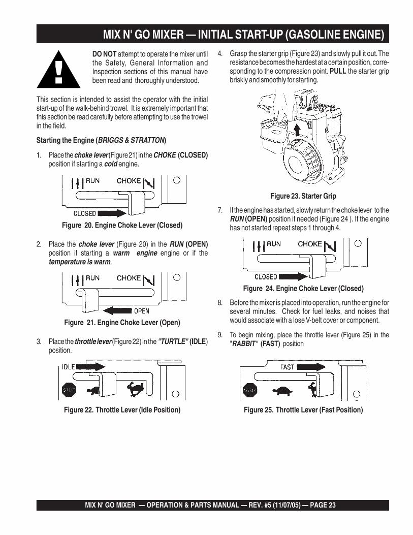
1. Place the choke lever (Figure 21) in the CHOKE (CLOSED)position if starting a cold engine.
DO NOT attempt to operate the mixer untilthe Safety, General Information andInspection sections of this manual havebeen read and thoroughly understood.
3. Place the throttle lever (Figure 22) in the "TURTLE" (IDLE)position.
Figure 22. Throttle Lever (Idle Position)
4. Grasp the starter grip (Figure 23) and slowly pull it out. Theresistance becomes the hardest at a certain position, corre-sponding to the compression point. PULL the starter gripbriskly and smoothly for starting.
Figure 23. Starter Grip
This section is intended to assist the operator with the initialstart-up of the walk-behind trowel. It is extremely important thatthis section be read carefully before attempting to use the trowelin the field.
2. Place the choke lever (Figure 20) in the RUN (OPEN)position if starting a warm engine engine or if thetemperature is warm.
7. If the engine has started, slowly return the choke lever to theRUN (OPEN) position if needed (Figure 24 ). If the enginehas not started repeat steps 1 through 4.
8. Before the mixer is placed into operation, run the engine forseveral minutes. Check for fuel leaks, and noises thatwould associate with a lose V-belt cover or component.
9. To begin mixing, place the throttle lever (Figure 25) in the"RABBIT" (FAST) position
Figure 24. Engine Choke Lever (Closed)
Figure 25. Throttle Lever (Fast Position)
Figure 21. Engine Choke Lever (Open)
Figure 20. Engine Choke Lever (Closed)
PAGE 24 —MIX N' GO MIXER — OPERATION & PARTS MANUAL — REV. #5 (1/07/05)
MIX N' GO MIXER — INITIAL START-UP (GASOLINE ENGINE)
Figure 26. Throttle Lever (Idle Position)
2. After the engine cools, move the throttle lever to the STOPposition (Figure 27).
Figure 27. Throttle Lever (Stop Position)
Stopping The Engine
Normal Shutdown1. Move the throttle lever to the "TURTLE" (IDLE) position
(Figure 26) and run the engine for three minutes at low speed.
Emergency Showdown
1. Move the throttle lever quickly to the OFF position (Figure28).
Figure 28. Throttle Lever (Stop Position)
MIX N' GO MIXER — OPERATION & PARTS MANUAL — REV. #5 (11/07/05) — PAGE 25
MIX N' GO MIXER — MAINTENANCE
Maintenance
Gearbox Oil Check
1. Position the mixer on a level surface and place a support blockunder the front of the mixer frame as shown in Figure 29. Thiswill level the mixer.
2. NEVER! check the gearbox oil level with the mixer tilted up ordown. ALWAYS check the gearbox oil level with the mixer in alevel position.
Figure 29. Mixer Positioning (Gearbox Oil Level)
5. Insert oil filler plug and tighten.
Figure 30. Gearbox Oil Level Check
Gerarbox Removal
1. Remove drum by turning counter-clockwise to release fromgearbox shaft.
2. Remove pulley, remember the nut securing the pulley isleft-hand threaded. Remove circlip, and draw out shaft.
3. Remove the 5 bolts securing rear plate.
4. Reassemble in reverse order, taking care to ensure gear teethare meshed correctly.
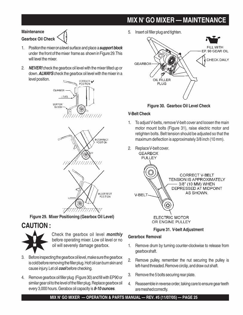
V-Belt Check
1. To adjust V-belts, remove V-belt cover and loosen the mainmotor mount bolts (Figure 31), raise electric motor andretighten bolts. Belt tension should be adjusted so that themaximum deflection is approximately 3/8 inch (10 mm).
2. Replace V-belt cover.
CAUTION :Check the gearbox oil level monthlybefore operating mixer. Low oil level or nooil will severely damage gearbox.
3. Before inspecting the gearbox oil level, make sure the gearboxis cold before removing the filler plug. Hot! oil can burn skin andcause injury. Let oil cool before checking.
4. Remove gearbox oil filler plug (Figure 30) and fill with EP90 orsimilar gear oil to the level of the filler plug. Replace gearbox oilevery 3,000 hours. Gerabox oil capacity is 8-10 ounces.
Figure 31. V-belt Adjustment
PAGE 26 —MIX N' GO MIXER — OPERATION & PARTS MANUAL — REV. #5 (1/07/05)
MIX N' GO MIXER — MAINTENANCE (GASOLINE ENGINE)
Reference manufacturer enginemanual for specific servicinginstructions.
NOTE
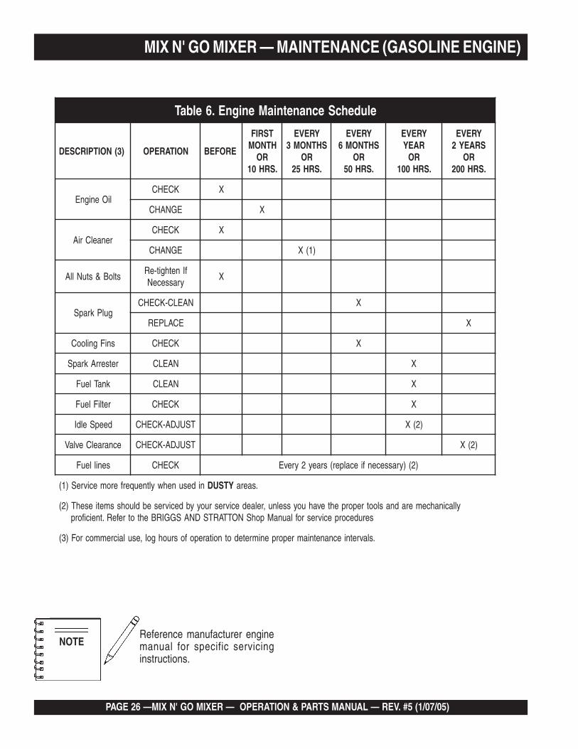
eludehcSecnanetniaMenignE.6elbaT
)3(NOITPIRCSED NOITAREPO EROFEB
TSRIFHTNOM
RO.SRH01
YREVESHTNOM3
RO.SRH52
YREVESHTNOM6
RO.SRH05
YREVERAEY
RO.SRH001
YREVESRAEY2
RO.SRH002
liOenignEKCEHC X
EGNAHC X
renaelCriAKCEHC X
EGNAHC )1(X
stloB&stuNllAfInethgit-eR
yrasseceNX
gulPkrapSNAELC-KCEHC X
ECALPER X
sniFgnilooC KCEHC X
retserrAkrapS NAELC X
knaTleuF NAELC X
retliFleuF KCEHC X
deepSeldI TSUJDA-KCEHC )2(X
ecnaraelCevlaV TSUJDA-KCEHC )2(X
senilleuF KCEHC )2()yrassecenfiecalper(sraey2yrevE
nidesunehwyltneuqerferomecivreS)1( YTSUD .saera
yllacinahcemeradnaslootreporpehtevahuoysselnu,relaedecivresruoyybdecivresebdluohssmetiesehT)2(serudecorpecivresroflaunaMpohSNOTTARTSDNASGGIRBehtotrefeR.tneiciforp
.slavretniecnanetniamreporpenimretedotnoitarepofosruohgol,esulaicremmocroF)3(
MIX N' GO MIXER — OPERATION & PARTS MANUAL — REV. #5 (11/07/05) — PAGE 27
MaintenancePerform the scheduled maintenance procedures as definded byTable 6 and below:
DAILY
■ Thoroughly remove dirt and oil from the engine and controlarea. Clean or replace the air cleaner elements as necessary.Check and retighten all fasteners as necessary. Check thegearbox for oil leaks. Repair or replace as needed.
WEEKLY
■ Remove the fuel filter cap and clean the inside of the fueltank.
■ Remove or clean the filter at the bottom of the tank.
■ Remove and clean the spark plug (Figure 32), then adjustthe spark gap to 0.024 ~0.028 inch (0.6~0.7 mm). This unithas electronic ignition, which requires no adjustments.
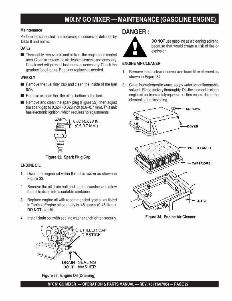
Figure 34. Engine Air Cleaner
DO NOT use gasoline as a cleaning solvent,because that would create a risk of fire orexplosion.
DANGER :
ENGINE AIR CLEANER
1. Remove the air cleaner cover and foam filter element asshown in Figure 34.
2. Clean foam element in warm, soapy water or nonflammablesolvent. Rinse and dry thoroughly. Dip the element in cleanengine oil and completely squeeze out the excess oil from theelement before installing.
ENGINE OIL
1. Drain the engine oil when the oil is warm as shown inFigure 33.
2. Remove the oil drain bolt and sealing washer and allowthe oil to drain into a suitable container.
3. Replace engine oil with recommended type oil as listedin Table 4. Engine oil capacity is .48 quarts (0.45 liters).DO NOT overfill.
4. Install drain bolt with sealing washer and tighten securly.
Figure 33. Engine Oil (Draining)
Figure 32. Spark Plug Gap
MIX N' GO MIXER — MAINTENANCE (GASOLINE ENGINE)
PAGE 28 —MIX N' GO MIXER — OPERATION & PARTS MANUAL — REV. #5 (1/07/05)
MIX N' GO MIXER — PREPARATION FOR LONG -TERM STORAGEMixer Storage
For storage of the mixer for over 30 days, the following isrecommended:
Drain the fuel tank completely, or add STA-BIL to thefuel.
Run the engine until the fuel is completely consumed.
Completely drain used oil from the engine crankcaseand fill with fresh clean oil, then follow the proceduresdescribed in the engine manual for engine storage.
Clean the entire mixer and engine compartment.
Cover the mixer and place it a clean dry area, that isprotected from harsh elements.
MIX N' GO MIXER — OPERATION & PARTS MANUAL — REV. #5 (11/07/05) — PAGE 29
NOTE PAGE
PAGE 30 —MIX N' GO MIXER — OPERATION & PARTS MANUAL — REV. #5 (1/07/05)
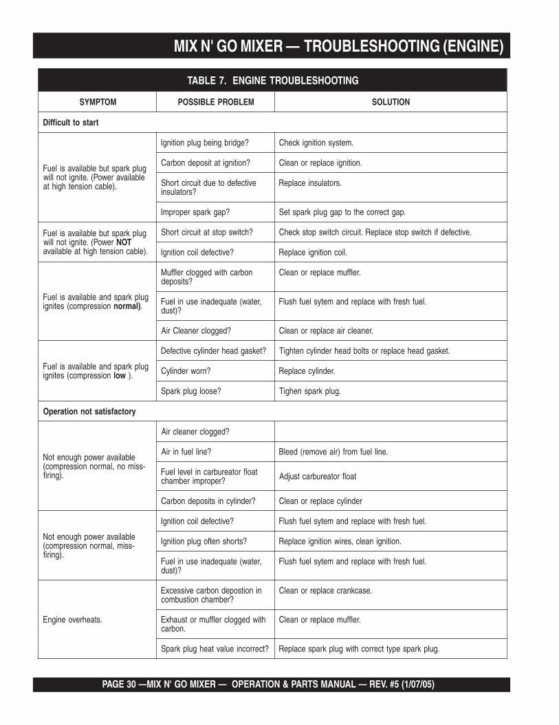
MIX N' GO MIXER — TROUBLESHOOTING (ENGINE)
GNITOOHSELBUORTENIGNE.7ELBAT
MOTPMYS MELBORPELBISSOP NOITULOS
tratsottluciffiD
gulpkrapstubelbaliavasileuFelbaliavarewoP(.etingitonlliw
.)elbacnoisnethgihta
?egdirbgniebgulpnoitingI .metsysnoitingikcehC
?noitingitatisopednobraC .noitingiecalperronaelC
evitcefedoteudtiucrictrohS?srotalusni
.srotalusniecalpeR
?pagkrapsreporpmI .pagtcerrocehtotpaggulpkrapsteS
gulpkrapstubelbaliavasileuFrewoP(.etingitonlliw TON
.)elbacnoisnethgihtaelbaliava
?hctiwspotstatiucrictrohS .evitcefedfihctiwspotsecalpeR.tiucrichctiwspotskcehC
?evitcefedliocnoitingI .liocnoitingiecalpeR
gulpkrapsdnaelbaliavasileuFnoisserpmoc(setingi )lamron .
nobrachtiwdeggolcrelffuM?stisoped
.relffumecalperronaelC
,retaw(etauqedaniesunileuF?)tsud
.leufhserfhtiwecalperdnametysleufhsulF
?deggolcrenaelCriA .renaelcriaecalperronaelC
gulpkrapsdnaelbaliavasileuFnoisserpmoc(setingi wol .)
?teksagdaehrednilycevitcefeD .teksagdaehecalperrostlobdaehrednilycnethgiT
?nrowrednilyC .rednilycecalpeR
?esoolgulpkrapS .gulpkrapsnehgiT
yrotcafsitastonnoitarepO
elbaliavarewophguonetoN-ssimon,lamronnoisserpmoc(
.)gnirif
?deggolcrenaelcriA
?enilleufniriA .enilleufmorf)riaevomer(deelB
taolfrotaerubracnilevelleuF?reporpmirebmahc taolfrotaerubractsujdA
?rednilycnistisopednobraC rednilycecalperronaelC
elbaliavarewophguonetoN-ssim,lamronnoisserpmoc(
.)gnirif
?evitcefedliocnoitingI .leufhserfhtiwecalperdnametysleufhsulF
?strohsnetfogulpnoitingI .noitinginaelc,seriwnoitingiecalpeR
,retaw(etauqedaniesunileuF?)tsud
.leufhserfhtiwecalperdnametysleufhsulF
.staehrevoenignE
ninoitsopednobracevissecxE?rebmahcnoitsubmoc
.esacknarcecalperronaelC
htiwdeggolcrelffumrotsuahxE.nobrac
.relffumecalperronaelC
?tcerrocnieulavtaehgulpkrapS .gulpkrapsepyttcerrochtiwgulpkrapsecalpeR
MIX N' GO MIXER — OPERATION & PARTS MANUAL — REV. #5 (11/07/05) — PAGE 31
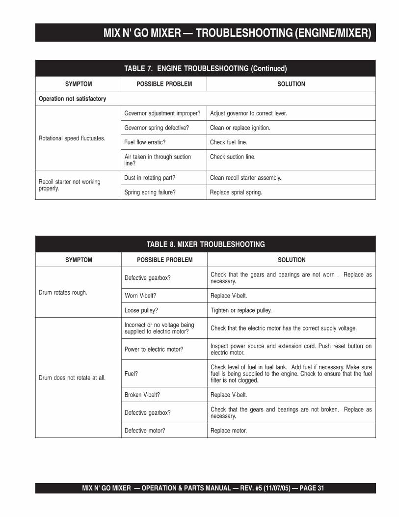
MIX N' GO MIXER — TROUBLESHOOTING (ENGINE/MIXER)
GNITOOHSELBUORTREXIM.8ELBAT
MOTPMYS MELBORPELBISSOP NOITULOS
.hguorsetatormurD
?xobraegevitcefeD saecalpeR.nrowtonerasgniraebdnasraegehttahtkcehC.yrassecen
?tleb-VnroW .tleb-VecalpeR
?yellupesooL .yellupecalperronethgiT
.llataetatortonseodmurD
gniebegatlovonrotcerrocnI?rotomcirtceleotdeilppus .egatlovylppustcerrocehtsahrotomcirtceleehttahtkcehC
?rotomcirtceleotrewoP nonottubteserhsuP.drocnoisnetxednaecruosrewoptcepsnI.rotomcirtcele
?leuFerusekaM.yrassecenfileufddA.knatleufnileuffolevelkcehCleufehttahterusneotkcehC.enigneehtotdeilppusgniebsileuf
.deggolctonsiretlif
?tleb-VnekorB .tleb-VecalpeR
?xobraegevitcefeD saecalpeR.nekorbtonerasgniraebdnasraegehttahtkcehC.yrassecen
?rotomevitcefeD .rotomecalpeR
)deunitnoC(GNITOOHSELBUORTENIGNE.7ELBAT
MOTPMYS MELBORPELBISSOP NOITULOS
yrotcafsitastonnoitarepO
.setautculfdeepslanoitatoR
?reporpmitnemtsujdaronrevoG .reveltcerrocotronrevogtsujdA
?evitcefedgnirpsronrevoG .noitingiecalperronaelC
?citarrewolfleuF .enilleufkcehC
noitcushguorhtninekatriA?enil
.enilnoitcuskcehC
gnikrowtonretratslioceR.ylreporp
?trapgnitatornitsuD .ylbmessaretratsliocernaelC
?eruliafgnirpsgnirpS .gnirpslairpsecalpeR
PAGE 32 —MIX N' GO MIXER — OPERATION & PARTS MANUAL — REV. #5 (1/07/05)
How to read the marks and remarks used in this partsbook.
Items Found In the “Remarks” Column
Serial Numbers-Where indicated, this indicates a serialnumber range (inclusive) where a particular part is used.
Model Number-Where indicated, this shows that thecorresponding part is utilized only with this specific modelnumber or model number variant.
Items Found In the “Items Number” Column
All parts with same symbol in the number column, *, #, +, %, or■, belong to the same assembly or kit.
Note: If more than one of the same reference number is listed,the last one listed indicates newest (or latest) part available.
The contents of this partscatalog are subject to changewithout notice.
If more than one of the samereference number is listed, thelast one listed indicates newest(or latest) part available.
NOTE
NOTE
MIX N' GO MIXER — EXPLANATION OF CODE IN REMARKS COLUMN
MIX N' GO MIXER — OPERATION & PARTS MANUAL — REV. #5 (11/07/05) — PAGE 33
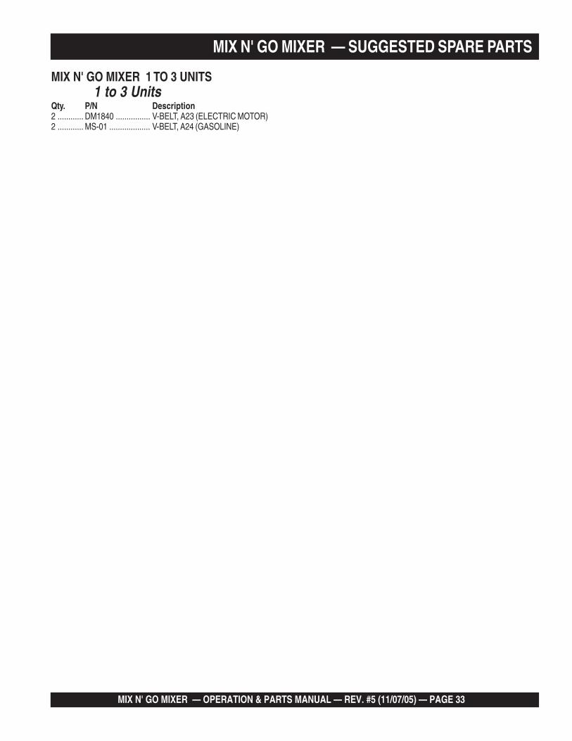
MIX N' GO MIXER — SUGGESTED SPARE PARTS
MIX N' GO MIXER 1 TO 3 UNITS1 to 3 Units
Qty. P/N Description2 ............ DM1840 ................ V-BELT, A23 (ELECTRIC MOTOR)2 ............ MS-01 ................... V-BELT, A24 (GASOLINE)
PAGE 34 —MIX N' GO MIXER — OPERATION & PARTS MANUAL — REV. #5 (1/07/05)
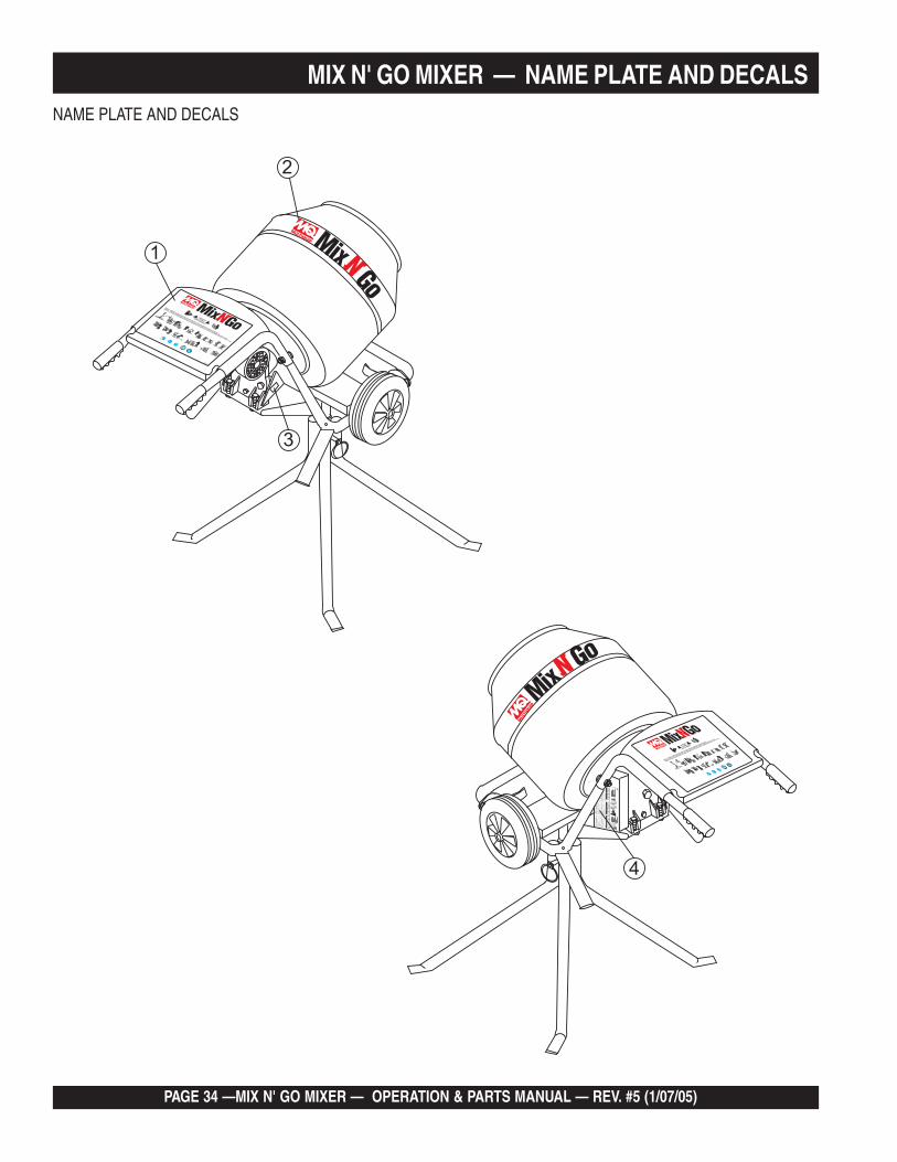
MIX N' GO MIXER — NAME PLATE AND DECALSNAME PLATE AND DECALS
WARNING!
ALARMA!
AVERTISSEMENT!
ENGLISH - WARNING! TO REDUCE THE RISK OF INJURY, USER MUST READ AND UNDERSTAND INSTRUCTION MANUAL
ESPAÑOL - ATENCION! PARA REDUCIR EL RIESGO DEL LESIONES EL USUARIO DEBE LEER Y ENTENDER EL MANUAL DE INSTRUCCIONES
FRANÇAIS - ATTENTION! AFIN DE DIMINUER LE RISQUE DE BLESSURES L’UTILISATEUR DOIT LIRE ET COMPRENDRE CE MANUEL D’ INSTRUCTIONS
DCL251
2
1
4
6.ch
eck
V-b
eltb
efor
est
artin
gm
ixer
.A
L WA
YS
1.R
ead
owne
r ’s
man
ualb
efor
eop
erat
ing
mix
er.
EL
EC
TR
ICM
OT
OR
Mak
esu
repo
wer
cord
has
been
disc
onne
cted
from
pow
erso
urc e
befo
recl
eani
ngm
ixer
.
use
anex
tens
ion
cord
ofpr
oper
siz e
,see
char
tbe
low
:A
LWA
YS
50fe
et(1
5.24
met
ers)
No.
12W
ireN
o.10
Wire
No.
8W
ireN
o.6
Wire
100
feet
(30.
48m
eter
s)75
feet
(22.
86m
eter
s)20
0fe
et(6
0.96
met
ers)
EX
TE
NS
ION
CO
RD
SIZ
E
Thi
sel
ectr
icm
otor
isfo
r.
115
VA
Co
per
atio
non
ly
GA
SO
LIN
EE
NG
INE
Mak
esu
reen
gine
istu
rned
offa
ndsp
ark
plug
wire
isdi
scon
nect
edbe
fore
clea
ning
mix
er.
oper
ate
mix
erin
anen
clos
edar
ea,p
rope
rve
ntila
tion
isre
quire
d.D
ON
OT st
opth
een
gine
and
allo
wen
gine
toco
olbe
fore
addi
ngfu
elor
oil.
AL W
AY
S chec
kfu
el,o
ilan
dai
rfil
ter
befo
rest
artin
gen
gine
.A
LWA
YS
MO
TE
UR
ÉL
EC
TR
IQU
EA
ssur
esvo
usto
ujou
rsqu
ele
cabl
ea
été
débr
anch
éde
lapr
ise
deco
uran
t ava
ntde
netto
yer
lem
alax
eur .
Ilfa
utto
ujou
rsut
ilise
run
era
llong
ede
t aill
eap
prop
riée,
veui
llez
s ’il
vous
réfé
rer
audi
agra
mm
esu
ivan
t:
Ce
mot
eur
élec
triq
ueà
été
conç
upo
uro
pér
atio
nà
1 15
volt
sse
ulem
ent.
MO
TE
UR
ÀE
SS
EN
CE
Ass
urez
vous
que
lem
oteu
res
tar
rêté
etqu
ele
filde
labo
ugie
est
débr
anch
éav
ant d
ene
ttoye
rle
mal
axeu
r .
pas
lem
alax
eur
dans
unen
droi
tfer
mé,
iles
tné
ces s
aire
detr
avai
ller
dans
unen
droi
tave
cun
ebo
nne
aéra
tion.
N’ U
TIL
ISE
Z touj
ours
véla
cour
roie
avan
t de
met
tre
lem
alax
eur
enm
arch
e.V
EU
ILL
EZ to
ujou
rsle
nive
aud’
ess e
nce
etd ’
huile
ains
i que
lefil
tre
àai
rav
ant d
em
ettr
ele
mot
eur
enm
arch
e.V
ÉR
IFIE
Z
RE
MO
VE
BO
L TA
ND
FIL
LW
ITH
EP .
90G
EA
RO
ILR
EM
OV
EB
OLT
AN
DF
I LL
WI T
HE
P .90
GE
AR
OIL
ELE
CT
RIC
MO
TO
RE
LEC
TR
ICM
OT
OR
CH
EC
KD
AIL
YC
HE
CK
DA
I LY
NE
VE
R!
OP
ER
AT
EM
IXE
RW
ITH
V-B
EL T
CO
VE
RR
EM
OV
ED
.N
EV
ER
!O
PE
RA
TE
MIX
ER
WIT
HV
-BE
LTC
OV
ER
RE
MO
VE
D.
MO
TO
RE
LÉC
TR
ICO
MO
TO
RE
LÉC
TR
I CO
MO
TE
UR
ÉLE
CT
RIQ
UE
MO
TE
UR
ÉLE
CT
RIQ
UE
RE
VIS
AR
DIA
RIO
RE
VIS
AR
DI A
RIO
ÔT
EZ
LEB
OU
LON
ET
RE
MP
LIS
SE
ZA
VE
CD
EI ’H
UIL
EE
P .90
ÀE
NG
RE
NA
GE
S
ÔT
EZ
LEB
OU
LON
ET
RE
MP
LIS
SE
ZA
VE
CD
EI’H
UIL
EE
P.90
ÀE
NG
RE
NA
GE
S
2.K
eep
unau
thor
ized
and
untr
aine
dpe
ople
away
from
mix
erdu
ring
oper
atio
n.3.
Mak
esu
real
lsaf
ety
devi
c es
(gua
rds)
are
inpl
ace
befo
rem
ixer
isst
arte
d.4.
Kee
pha
nds
and
finge
rsaw
ayfr
omm
ovin
gob
ject
s.5.
leav
em
ixer
unat
tend
edw
hen
oper
atin
g.N
EV
ER
6.in
spec
cion
ela
band
aan
tes
deen
cend
erla
mez
c lad
ora.
SIE
MP
RE
1.Le
ael
man
uald
eop
erac
ióan
tes
deus
arla
mez
c lad
ora.
2.M
ante
nga
pers
onas
que
noes
tén
auto
rizad
aso
cap a
cit a
das
alej
ades
dela
mez
c lad
ora
d ura
nte
elfu
ncio
nam
ient
ode
lam
áqui
na.
3.A
segú
res e
que
todo
slo
sap
arat
osde
segu
ridad
esté
ntr
abaj
ando
apro
piad
amen
tean
tes
deus
arla
mez
c lad
ora.
4.M
ante
nga
las
mon
osy
dedo
sal
ejad
osde
obje
tos
enm
ovim
into
.5.
seal
eje
dela
mez
clao
ram
ient
ras
ést a
,est
etr
abaj
ando
!N
UN
CA
6.to
ujou
rsvé
rifie
rla
cour
roie
avan
t de
met
tre
lem
alax
eur
enm
arch
e.V
EU
ILL
EZ
1.Li
sez
lem
anua
ld’u
tilis
atio
nav
ant d
’util
iser
lele
mal
axeu
r .2.
Seu
lun
pers
onne
l qua
lifié
peut
être
auth
oris
éà
setr
ouve
rà
prox
imité
dum
alax
eur
quan
dil
est e
nop
érat
ion.
3.A
ssur
ezvo
usqu
eto
usle
sdi
spos
itifs
desé
c urit
éso
nten
plac
eav
ant
dem
ettr
ele
mal
axeu
ren
mar
che.
4.G
arde
zle
sm
ains
etdo
igt s
loin
deto
ute
piè
enm
ouve
men
t.5.
jam
ais
lem
alax
eur
sans
surv
eilla
nce
quan
dil
est e
nop
érat
ion.
NE
LA
ISS
EZ
WA
RN
ING
!A
DV
ER
TE
NC
IA!
AV
ER
TIS
SE
ME
NT
!
NU
NC
A!
MA
NE
JELA
ME
ZC
LAD
OR
AS
INLA
CO
BE
RT
UR
AD
EB
AN
DA
-VR
EM
OV
IDA
.
NU
NC
A!
MA
NE
J ELA
ME
ZC
LAD
OR
AS
INLA
CO
BE
RT
UR
AD
EB
AN
DA
-VR
EM
OV
IDA
.
N’U
TIL
ISE
Z!
JAM
AIS
LEM
ALA
XE
UR
SA
NS
LEC
OU
VE
RC
LED
ELA
CO
UR
RO
IE.
N’U
TIL
ISE
Z!
J AM
AIS
LEM
ALA
XE
UR
SA
NS
LEC
OU
VE
RC
LED
ELA
CO
UR
RO
IE.
DC
L250
DC
L250
MO
TO
RE
LÉ
CT
RIC
OA
segú
res e
que
elca
ble
deco
rrie
nte
esté
deem
peza
ra
limpi
arla
mez
c lad
ora.
use
elt a
mañ
ode
exte
nsio
nes
deal
ambr
ein
dica
doco
mo
mue
stra
eldi
agra
ma
abaj
o:S
IEM
PR
E
Est
em
otor
elét
rico
está
de.
sola
men
teca
pac
itad
op
ara
corr
ien
teal
tern
a11
5vo
ltio
s
MÁ
QU
INA
SD
EG
AS
OL
INA
Ase
gure
que
lam
áqui
naes
teap
agad
ay
elal
ambr
ede
labu
jíaes
tede
scon
ect a
doan
tes
deem
peza
ra
limpi
arla
mez
c lad
ora.
enci
enda
lam
ezc l
ador
aen
una
área
cerr
ada;
esne
ces a
rioes
t ar
enun
aár
eaqu
ete
nga
apro
piad
ave
ntila
c ión
.N
O
apag
uela
máq
uina
ype
rmit a
que
seen
frie
ante
sde
pone
rlega
solin
ao
acei
te.
SIE
MP
RE re
vis e
laga
solin
a,ac
eite
, yel
filtr
ode
lair
ante
sde
ence
nder
lam
áqui
na.
SIE
MP
RE
50pi
eds
(15.
24m
étre
s)
Cab
leN
umér
o12
TAIL
LED
ELA
RA
LLO
NG
EC
able
Num
éro
10C
able
Num
éro
8C
able
Num
éro
6
50pi
eds
(15.
24m
étre
s)50
pied
s(1
5.24
mét
res)
50pi
eds
(15.
24m
étre
s)50
pies
(15.
24m
etro
s)
Ala
mbr
eN
umér
o12
100
pies
(30.
48m
etro
s)75
pies
(22.
86m
etro
s)20
0pi
es(6
0.96
met
ros)
TAM
AÑ
OD
EE
XT
EN
SIÓ
NA
lam
bre
Num
éro
10A
lam
bre
Num
éro
8A
lam
bre
Num
éro
6
VÉ
RIF
IEZ
QU
OT
IDIE
NN
EM
EN
TV
ÉR
IFIE
ZQ
UO
TID
IEN
NE
ME
NT
ELE
CT
RIC
MO
TO
RE
LEC
TR
ICM
OT
OR
MO
TO
RE
LÉC
TR
ICO
MO
TO
RE
LÉC
TR
ICO
MO
TE
UR
ÉLE
CT
RIQ
UE
MO
TE
UR
ÉL E
CT
RIQ
UE
RE
MO
VE
RE
LT
OR
ÑIL
LOY
LLE
NA
RC
ON
AC
EIT
ED
EE
NG
RN
AJE
EP .
90
RE
MO
VE
RE
LT
OR
ÑIL
LOY
LLE
NA
RC
ON
AC
EIT
ED
EE
NG
RN
AJE
EP.
90
3
WARNING!
ALARMA!
AVERTISSEMENT!
ENGLISH - WARNING! TO REDUCE THE RISK OF INJURY, USER MUST READ AND UNDERSTAND INSTRUCTION MANUAL
ESPAÑOL - ATENCION! PARA REDUCIR EL RIESGO DEL LESIONES EL USUARIO DEBE LEER Y ENTENDER EL MANUAL DE INSTRUCCIONES
FRANÇAIS - ATTENTION! AFIN DE DIMINUER LE RISQUE DE BLESSURES L’UTILISATEUR DOIT LIRE ET COMPRENDRE CE MANUEL D’ INSTRUCTIONS
MIX N' GO MIXER — OPERATION & PARTS MANUAL — REV. #5 (11/07/05) — PAGE 35
MIX N' GO MIXER — NAME PLATE AND DECALS
NAME PLATE AND DECALS
NAMEPLATE AND DECALS.NO PART NO PART NAME QTY. REMARKS1* DCL251 DECAL: WARNING MQ 12* 510165 DECAL: MQ MIX N GO 13 DECAL: NAMEPLATE ............................... 1 ............ CONTACT MQ PARTS DEPT.4* DCL250 DECAL: WARNING MAINTENANCE 1
SEE DECAL ILLUSTRATIONS ON PAGES 11 AND 12.
PAGE 36 —MIX N' GO MIXER — OPERATION & PARTS MANUAL — REV. #5 (1/07/05)
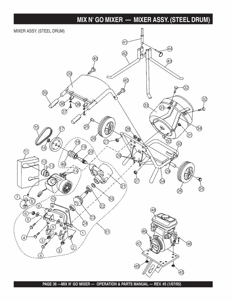
MIXER ASSY. (STEEL DRUM)
MIX N' GO MIXER — MIXER ASSY. (STEEL DRUM)
MIX N' GO MIXER — OPERATION & PARTS MANUAL — REV. #5 (11/07/05) — PAGE 37
MIX N' GO MIXER — MIXER ASSY. (STEEL DRUM)MIXER ASSY. (STEEL DRUM)
NO. PART NO. PART NAME QTY. REMARKS1# DM3150 HEX HEAD BOLT M12 x 70 12# DM1356 OIL FILLER PLUG M14 x 2 x 15L 13# DM1912 HEX NUT M10 24# DM355 HEX HEAD BOLT M8 x P1.25 x 24L 35# DM3151 FLAT WASHER M12 26# DM3152 HEX NUT M12 17 SP9012 TOGGLE SWITCH .................................... 1 ......... INCLUDES ITEM W/*8* SWITCH, BOOT 19# DM1320 GEAR BOX BACK COVER 110# DM1357 GEAR BOX SEAL 11 DM1380 BELT GUARD 112 DM1821 DRIVE PULLEY ........................................ 1 ......... ELECTRIC MOTOR ONLY13 DM1822 SET SCREW M6 x 12L 114 DM2020 BOLT M6 x 18 215 DM1840 V-BELT, A23 ............................................. 1 ......... ELECTRIC MOTOR ONLY16# DM1332 NUT M12 117# DM1810 GEARBOX PULLEY 118# DM1353 OIL SEAL 20 x 42.5 x 10 119# DM1352 BEARING RACE 6004 120# DM1331 WORM GEAR 121# DM1310 GEARBOX CASE 122# DM1351 BEARING RACE 6006 123# DM1333 GEAR & SHAFT 124 DM1351 BEARING RACE 6006 125 DM1720 WHEEL RETAINER 226 DM1710 WHEEL, RUBBER, HARD 227 DM1641 HEX NUT M8 228 DM2021 NUT 229 DM1911 HEX HEAD BOLT M10 x P1.5 x 40L 330 DM1141 DRUM LOCK 131 DM1527 HEX NUT M10 232 DM1524 BOLT 233 DM1400 STEEL BARREL 134 DM1414 BLADE, STEEL BARREL 235 DM1613 HANDLE GRIP, RUBBER 236 DM1630 TOP COVER CLAMP 237 DM1631 SCREW 5.5 x 25 238 DM1632 LOCK WASHER 239 DM1620 TOP COVER, PLASTIC 140 DM1640 BOLT M8 SPECIAL DOME HEAD 241 DM1221 STAND, ADAPTER 142 DM1212 STAND, BOTTOM LH (2 BOSS) 143 DM1213 STAND, BOTTOM RH (1 BOSS) 144 DM1231 CLIP LINCH PIN 145 DM3050 NUT M8BOLT M8 x 35 446 DM3051 BOLT M8 x 35 447 DM3000 ENGINE MOUNT (GASOLINE) 148 912321040E1 ENGINE, 3.5 HP BRIGGS & STRATTON 149# DM1358 RETAINER RING 150 34579 MOTOR, ELECTRIC 3/4 H.P. 151 DM1300 GEARBOX ASSEMBLY ................................... 1 ......... INCLUDES ITEMS/#52 MS01 V-BELT, A24 .................................................... 1 ......... GASOLINE ENGINE ONLY53 EM901006 DRIVE PULLEY............................................... 1 ......... GASOLINE ENGINE ONLY54 DM1100 MAIN FRAME 155 DM1354 SEAL, OIL 1
PAGE 38 —MIX N' GO MIXER — OPERATION & PARTS MANUAL — REV. #5 (1/07/05)
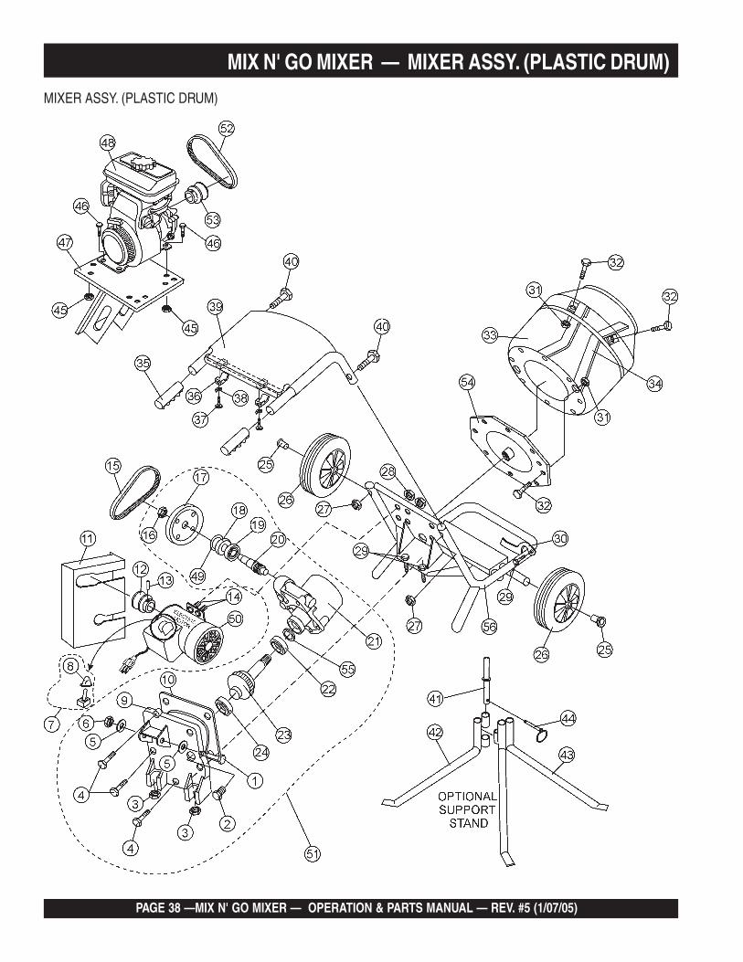
MIXER ASSY. (PLASTIC DRUM)
MIX N' GO MIXER — MIXER ASSY. (PLASTIC DRUM)

MIX N' GO MIXER — OPERATION & PARTS MANUAL — REV. #5 (11/07/05) — PAGE 39
MIX N' GO MIXER — MIXER ASSY. (PLASTIC DRUM)MIXER ASSY. (PLASTIC DRUM)NO. PART NO. PART NAME QTY. REMARKS1# DM3150 HEX HEAD BOLT M12 x 70 12# DM1356 OIL FILLER PLUG M14 x 2 x 15L 13# DM1912 HEX NUT M10 24# DM355 HEX HEAD BOLT M8 x P1.25 x 24L 35# DM3151 FLAT WASHER M12 26# DM3152 HEX NUT M12 17 SP9012 TOGGLE SWITCH .................................... 1 ......... INCLUDES ITEM W/*8* SWITCH, BOOT 19# DM1320 GEAR BOX BACK COVER 110# DM1357 GEAR BOX SEAL 11 DM1380 BELT GUARD 112 DM1821 DRIVE PULLEY ........................................ 1 ......... ELECTRIC MOTOR ONLY13 DM1822 SET SCREW M6 x 12L 114 DM2020 BOLT M6 x 18 215 DM1840 V-BELT, A23 ............................................. 1 ......... ELECTRIC MOTOR ONLY16 DM1332 NUT M12 117 DM1810 GEARBOX PULLEY 118# DM1353 OIL SEAL 20 x 42.5 x 10 119# DM1352 BEARING RACE 6004 120# DM1331 WORM GEAR 121# DM1310 GEARBOX CASE 122# DM1351 BEARING RACE 6006 123# DM1333 GEAR & SHAFT 124 DM1351 BEARING RACE 6006 125 DM1720 WHEEL RETAINER 226 DM1710 WHEEL, RUBBER, HARD 227 DM1641 HEX NUT M8 228 DM2021 NUT 228 DM1110 MAIN FRAME 129 DM1911 HEX HEAD BOLT M10 x P1.5 x 40L 330 DM1141 DRUM LOCK 131% DM1527 HEX NUT M10 1232% DM1524 BOLT 1233% DM1510 PLASTIC BARREL, BARE ....................... 1 ......... INCLUDES ITEMS/%34% DM1531 BLADE, BARREL 235 DM1613 HANDLE GRIP, RUBBER 236 DM1630 TOP COVER CLAMP 237 DM1631 SCREW 5.5 x 25 238 DM1632 LOCK WASHER 239 DM1620 TOP COVER, PLASTIC 140 DM1640 BOLT M8 SPECIAL DOME HEAD 241 DM1221 STAND, ADAPTER 142 DM1212 STAND, BOTTOM LH (2 BOSS) 143 DM1213 STAND, BOTTOM RH (1 BOSS) 144 DM1231 CLIP LINCH PIN 145 DM3050 NUT M8BOLT M8 x 35 446 DM3051 BOLT M8 x 35 447 DM3000 ENGINE MOUNT (GASOLINE) 148 912321040E1 ENGINE, 3.5 HP BRIGGS & STRATTON 149# DM1358 RETAINER RING 150 34579 MOTOR, ELECTRIC 3/4 H.P. 151 DM1300 GEARBOX ASSEMBLY ............................ 1 ......... INCLUDES ITEMS/#52 MS01 V-BELT, A24 ............................................. 1 ......... GASOLINE ENGINE ONLY53 EM901006 DRIVE PULLEY ........................................ 1 ......... GASOLINE ENGINE ONLY54% DM1521 MOUNTING PLATE 155 DM1354 OIL SEAL 156 DM1100 MAIN FRAME 1
PAGE 40 —MIX N' GO MIXER — OPERATION & PARTS MANUAL — REV. #5 (1/07/05)
TERMS AND CONDITIONS OF SALE — PARTSPAYMENT TERMS
Terms of payment for parts are net 10 days.
FREIGHT POLICY
All parts orders will be shipped collect orprepaid with the charges added to the invoice.All shipments are F.O.B. point of origin.Multiquip’s responsibility ceases when a signedmanifest has been obtained from the carrier,and any claim for shortage or damage must besettled between the consignee and the carrier.
MINIMUM ORDER
The minimum charge for orders from Multiquipis $15.00 net. Customers will be asked forinstructions regarding handling of orders notmeeting this requirement.
RETURNED GOODS POLICY
Return shipments will be accepted and creditwill be allowed, subject to the following provi-sions:
1. A Returned Material Authorization mustbe approved by Multiquip prior to ship-ment.
2. To obtain a Return Material Authorization,a list must be provided to Multiquip PartsSales that defines item numbers, quanti-ties, and descriptions of the items to bereturned.
a. The parts numbers and descriptionsmust match the current parts pricelist.
b. The list must be typed or computergenerated.
c. The list must state the reason(s) forthe return.
d. The list must reference the salesorder(s) or invoice(s) under which theitems were originally purchased.
e. The list must include the name andphone number of the person request-ing the RMA.
3. A copy of the Return Material Authoriza-tion must accompany the return shipment.
4. Freight is at the sender’s expense. Allparts must be returned freight prepaid toMultiquip’s designated receiving point.
5. Parts must be in new and resalablecondition, in the original Multiquip pack-age (if any), and with Multiquip partnumbers clearly marked.
6. The following items are not returnable:
a. Obsolete parts. (If an item is in theprice book and shows as beingreplaced by another item, it isobsolete.)
b. Any parts with a limited shelf life(such as gaskets, seals, “O” rings,and other rubber parts) that werepurchased more than six monthsprior to the return date.
c. Any line item with an extended dealernet price of less than $5.00.
d. Special order items.
e. Electrical components.
f. Paint, chemicals, and lubricants.
g. Decals and paper products.
h. Items purchased in kits.
7. The sender will be notified of anymaterial received that is not acceptable.
8. Such material will be held for fiveworking days from notification, pendinginstructions. If a reply is not receivedwithin five days, the material will bereturned to the sender at his expense.
9. Credit on returned parts will be issued atdealer net price at time of the originalpurchase, less a 15% restocking charge.
10. In cases where an item is accepted, forwhich the original purchase documentcan not be determined, the price will bebased on the list price that was effectivetwelve months prior to the RMA date.
11. Credit issued will be applied to futurepurchases only.
PRICING AND REBATES
Prices are subject to change without priornotice. Price changes are effective on a spe-cific date and all orders received on or afterthat date will be billed at the revised price.
Rebates for price declines and added chargesfor price increases will not be made for stock onhand at the time of any price change.
Multiquip reserves the right to quote and selldirect to Government agencies, and to OriginalEquipment Manufacturer accounts who use ourproducts as integral parts of their own products.
SPECIAL EXPEDITING SERVICE
A $35.00 surcharge will be added to the invoicefor special handling including bus shipments,insured parcel post or in cases where Multiquipmust personally deliver the parts to the carrier.
LIMITATIONS OF SELLER’S LIABILITY
Multiquip shall not be liable here under fordamages in excess of the purchase price of theitem with respect to which damages are claimed,and in no event shall Multiquip be liable for lossof profit or good will or for any other special,consequential or incidental damages.
LIMITATION OF WARRANTIES
No warranties, express or implied, are made inconnection with the sale of parts or trade acces-sories nor as to any engine not manufactured byMultiquip. Such warranties made in connectionwith the sale of new, complete units are madeexclusively by a statement of warrantypackaged with such units, and Multiquip neitherassumes not authorizes any person to assumefor it any other obligation or liability whatever inconnection with the sale of its products. Apartfrom such written statement of warranty, thereare no warranties, express, implied or statutory,which extend beyond the description of theproducts on the face hereof.
Effective: October 1, 2002

MIX N' GO MIXER — OPERATION & PARTS MANUAL — REV. #5 (11/07/05) — PAGE 41
NOTE PAGE
MULTIQUIP INC.POST OFFICE BOX 6254CARSON, CA 90749310-537-3700 • 800-421-1244FAX: 310-537-3927E-MAIL: [email protected]: multiquip.com
Atlanta • Boise • Dallas • Houston • NewarkQuebec, Canada • Manchester, UK • Rio De Janiero, BR • Guadalajara, MX
HERE'S HOW TO GET HELPPLEASE HAVE THE MODEL AND SERIAL NUMBERON-HAND WHEN CALLING
PARTS DEPARTMENT800-427-1244 or 310-537-3700FAX: 800-672-7877 or 310-637-3284
SERVICE DEPARTMENT/TECHNICAL ASSISTANCE800-478-1244 or 310-537-3700FAX: 310- 537-4259
WARRANTY DEPARTMENT888-661-4279, or 310-661-4279FAX: 310- 537-1173
MAIN800-421-1244 or 310-537-3700FAX: 310-537-3927
OPERATION AND PARTS MANUAL