Embed Size (px)
Citation preview

O P E R A T O R ’ S M A N U A L
GROOMING MOWERS
5WPMAN0765 (Rev. 8/6/2012)
FM3012REAR DISCHARGE

2 Introduction Frontier (Rev. 12/5/2011)
TO THE DEALER:
Assembly and proper installation of this product is the responsibility of the Frontier dealer. Read manual instructionsand safety rules. Make sure all items on the Dealer’s Pre-Delivery and Delivery Check Lists in the Operator’s Manualare completed before releasing equipment to the owner.
TO THE OWNER:
Read this manual before operating your Frontier equipment. The information presented will prepare you to do a betterand safer job. Keep this manual handy for ready reference. Require all operators to read this manual carefully andbecome acquainted with all the adjustment and operating procedures before attempting to operate. Replacementmanuals can be obtained from your selling dealer.
The equipment you have purchased has been carefully engineered and manufactured to provide dependable andsatisfactory use. Like all mechanical products, it will require cleaning and upkeep. Lubricate the unit as specified.Observe all safety information in this manual and safety decals on the equipment.
For service, your authorized Frontier dealer has trained mechanics, genuine Frontier service parts, and the necessarytools and equipment to handle all your needs.
Use only genuine Frontier service parts. Substitute parts will void the warranty and may not meet standards required forsafe and satisfactory operation. Record the model number and serial number of your equipment in the spacesprovided:
Model: ______________________________ Date of Purchase: _____________________
Serial Number: (see Safety Decal section for location) ____________________________________
Provide this information to your dealer to obtain correct repair parts.
Throughout this manual, the term NOTICE is used to indicate that failure to observe can cause damage to equipment.The terms CAUTION, WARNING and DANGER are used in conjunction with the Safety-Alert Symbol, (a triangle withan exclamation mark), to indicate the degree of hazard for items of personal safety.

Introduction 35WPMAN0765 (9/30/2009)
TABLE OF CONTENTS
INTRODUCTION . . . . . . . . . . . . . . . . . . . . . . . . . . . . . . . . . . . . . . . . . . . . . . 2SPECIFICATIONS. . . . . . . . . . . . . . . . . . . . . . . . . . . . . . . . . . . . . . . . . . . . . 3GENERAL INFORMATION . . . . . . . . . . . . . . . . . . . . . . . . . . . . . . . . . . . . . . 4SAFETY RULES . . . . . . . . . . . . . . . . . . . . . . . . . . . . . . . . . . . . . . . . . . . . 5 - 8SAFETY DECALS . . . . . . . . . . . . . . . . . . . . . . . . . . . . . . . . . . . . . . . . . . 9 - 12OPERATION . . . . . . . . . . . . . . . . . . . . . . . . . . . . . . . . . . . . . . . . . . . . . . . . 13OWNER SERVICE . . . . . . . . . . . . . . . . . . . . . . . . . . . . . . . . . . . . . . . . . . . 18TROUBLE SHOOTING . . . . . . . . . . . . . . . . . . . . . . . . . . . . . . . . . . . . . . . . 22DEALER SERVICE . . . . . . . . . . . . . . . . . . . . . . . . . . . . . . . . . . . . . . . . . . . 24ASSEMBLY . . . . . . . . . . . . . . . . . . . . . . . . . . . . . . . . . . . . . . . . . . . . . . . . . 30DEALER CHECK LISTS . . . . . . . . . . . . . . . . . . . . . . . . . . . . . . . . . . . . . . . 33PARTS LISTS . . . . . . . . . . . . . . . . . . . . . . . . . . . . . . . . . . . . . . . . . . . . . . . 35BOLT TORQUE CHART . . . . . . . . . . . . . . . . . . . . . . . . . . . . . . . . . . . . . . . 52BOLT SIZE CHART & ABBREVIATIONS . . . . . . . . . . . . . . . . . . . . . . . . . . 53INDEX . . . . . . . . . . . . . . . . . . . . . . . . . . . . . . . . . . . . . . . . . . . . . . . . . . . . . 54
SPECIFICATIONS
Cutting Width 12.5’
Cutting Height Range 1.0” - 4.5”
Shipping Weight (Approximately) 2,035 lbs.
Blade Speed (feet per minute) 16,200
Blade Spindles 9
Number of Blades 9
Universal Drive Series (Input: ASAE Cat 3 CV; Wing: ASAE Cat 3)
Transport Wheels 20.5” x 8.75” Turf tire and Wheel
Caster Wheels 4” x 10” Solid (10)
Tractor PTO Speed 540 rpm
Recommended Minimum Tractor Horsepower 25 - 60 hp
Si no lee Ingles, pida ayuda a alguien que si lo lea para que le
traduzca las medidas de seguridad.
LEA EL INSTRUCTIVO!!

4 Introduction 5WPMAN0765 (9/30/2009)
GENERAL INFORMATION
Some illustrations in this manual show theequipment with safety shields removed to providea better view. This equipment should never beoperated with any necessary safety shieldingremoved.
The purpose of this manual is to assist you in operatingand maintaining your Flex Wing Mower. Read it care-fully. It furnishes information and instructions that willhelp you achieve years of dependable performance.
These instructions have been compiled from extensivefield experience and engineering data. Some informa-tion may be general in nature, due to unknown andvarying operating conditions. However, through experi-ence and these instructions, you should be able todevelop procedures suitable to your particular situa-tion.
Throughout this manual, references are made to rightand left direction. These are determined by standingbehind the tractor facing the direction of forward travel.Blade rotation is counter-clockwise as viewed from thetop of the mower.
�������

Safety 5Frontier FM3012 (10/15/2009)
TRAINING
Safety instructions are important! Read allattachment and power unit manuals; follow allsafety rules and safety decal information. (Replace-ment manuals and safety decals are available fromyour dealer.) Failure to follow instructions or safetyrules can result in serious injury or death.
If you do not understand any part of this manualand need assistance, see your dealer.
Know your controls and how to stop engine andattachment quickly in an emergency.
Operators must be instructed in and be capableof the safe operation of the equipment, its attach-ments, and all controls. Do not allow anyone tooperate this equipment without proper instruc-tions.
Keep hands and body away from pressurizedlines. Use paper or cardboard, not hands or otherbody parts to check for leaks. Wear safety goggles.Hydraulic fluid under pressure can easily penetrateskin and will cause serious injury or death.
Make sure that all operating and service person-nel know that if hydraulic fluid penetrates skin, itmust be surgically removed as soon as possible bya doctor familiar with this form of injury or gan-grene, serious injury, or death will result. CON-TACT A PHYSICIAN IMMEDIATELY IF FLUIDENTERS SKIN OR EYES. DO NOT DELAY.
Never allow children or untrained persons tooperate equipment.
PREPARATION
Check that all hardware is properly installed.Always tighten to torque chart specificationsunless instructed otherwise in this manual.
Air in hydraulic systems can cause erratic oper-ation and allows loads or equipment componentsto drop unexpectedly. When connecting equipmentor hoses or performing any hydraulic maintenance,purge any air in hydraulic system by operating allhydraulic functions several times. Do this beforeputt ing into service or al lowing anyone toapproach the equipment.
Make sure all hydraulic hoses, fittings, andvalves are in good condition and not leaking beforestarting power unit or using equipment. Check androute hoses carefully to prevent damage. Hosesmust not be twisted, bent sharply, kinked, frayed,pinched, or come into contact with any movingparts. Operate moveable components through fulloperational range to check clearances. Replaceany damaged hoses immediately.
Always wear relatively tight and belted clothingto avoid entanglement in moving parts. Wearsturdy, rough-soled work shoes and protectiveequipment for eyes, hair, hands, hearing, and head;and respirator or filter mask where appropriate.
When attaching a pull-type unit to the tractordrawbar, always use a high-strength drawbar pin.The drawbar pin must have a device that will lock itinto position. Secure safety chain to attachmentand tractor.
Make sure attachment is properly secured,adjusted, and in good operating condition.
Make sure spring-activated locking pin or collarslides freely and is seated firmly in tractor PTOspline groove.
Before starting the power unit, check all equip-ment driveline guards for damage. Replace anydamaged guards. Make sure all guards rotate freelyon all drivelines. If guards do not rotate freely ondrivelines, repair and replace bearings before put-ting equipment into service.
(Safety Rules continued on next page)
Safety is a primary concern in the design andmanufacture of our products. Unfortunately, ourefforts to provide safe equipment can be wipedout by an operator’s single careless act.
In addition to the design and configuration ofequipment, hazard control and accident preven-tion are dependent upon the awareness, concern,judgement, and proper training of personnelinvolved in the operation, transport, maintenanceand storage of equipment.
It has been said “The best safety device is aninformed, careful operator.” We ask you to be thatkind of operator.
SAFETY RULESATTENTION! BECOME ALERT! YOUR SAFETY IS INVOLVED!

6 Safety Frontier FM3012 (10/15/2009)
(Safety Rules continued from previous page)
Power unit must be equipped with ROPS orROPS cab and seat belt. Keep seat belt securelyfastened. Falling off power unit can result in deathfrom being run over or crushed. Keep foldableROPS systems in “locked up” position at all times.
Inspect chain shielding before each use.Replace if damaged.
Remove accumulated debris from this equip-ment, power unit, and engine to avoid fire hazard.
Make sure all safety decals are installed.Replace if damaged. (See Safety Decals section forlocation.)
Make sure shields and guards are properlyinstalled and in good condition. Replace if dam-aged.
A minimum 20% of tractor and equipmentweight must be on the tractor front wheels whenattachments are in transport position. Without thisweight, tractor could tip over, causing personalinjury or death. The weight may be attained withfront wheel weights, ballast in tires or front tractorweights. Weigh the tractor and equipment. Do notestimate.
Inspect and clear area of stones, branches, orother hard objects that might be thrown, causinginjury or damage.
Never attach the mower release rope to theoperator, the operator's clothing, or the tractorseat.
Make test turns, both left and right. Check thatboth the hydraulic hose and the mower transportlock release rope do not become taut or caught onany parts of the tractor or mower.
TRANSPORTATION
The maximum transport speed for towed andsemi-mounted machines is 20 mph (32 km/h).Regardless of the maximum speed capability of thetowing tractor, do not exceed the implement’s max-imum transport speed. Doing so could result in:
• Loss of control of the implement and tractor• Reduced or no ability to stop during braking• Implement tire failure• Damage to the implement or its components.
Use additional caution and reduce speed whenunder adverse surface conditions, turning, or oninclines.
Do not operate PTO during transport.
Never tow this implement with a motor vehicle.
Always raise unit and install transport locksbefore transporting. Leak down or failure ofmechanical or hydraulic system can cause equip-ment to drop.
Never allow riders on power unit or attachment.
Always comply with all state and local lightingand marking requirements.
Do not operate PTO during transport.
Do not operate or transport equipment whileunder the influence of alcohol or drugs.
OPERATION
Only engage power when equipment is atground operating level. Always disengage powerwhen equipment is raised off the ground.
Do not allow bystanders in the area when oper-ating, attaching, removing, assembling, or servic-ing equipment.
Never walk, stand, or place yourself or othersunder a raised wing or in the path of a loweringwing. Hydraulic system leak-down, hydraulic sys-tem failures, mechanical failures, or movement ofcontrol levers can cause wings to drop unexpect-edly and cause severe injury or death.
Full chain shielding must be installed whenoperating in populated areas or other areas wherethrown objects could injure people or damageproperty.
• If this machine is not equipped with full chainshielding, operation must be stopped when any-one comes within 300 feet (92 m).• This shielding is designed to reduce the riskof thrown objects. The mower deck and protec-tive devices cannot prevent all objects fromescaping the blade enclosure in every mowingcondition. It is possible for objects to ricochetand escape, traveling as much as 300 feet (92 m).
Never direct discharge toward people, animals,or property.
Do not operate or transport equipment whileunder the influence of alcohol or drugs.
Operate only in daylight or good artificial light.
(Safety Rules continued on next page)
SAFETY RULESATTENTION! BECOME ALERT! YOUR SAFETY IS INVOLVED!

Safety 7Frontier FM3012 (10/15/2009)
(Safety Rules continued from previous page)
Keep hands, feet, hair, and clothing away fromequipment while engine is running. Stay clear of allmoving parts.
Always comply with all state and local lightingand marking requirements.
Never allow riders on power unit or attachment.
Power unit must be equipped with ROPS orROPS cab and seat belt. Keep seat belt securelyfastened. Falling off power unit can result in deathfrom being run over or crushed. Keep foldableROPS systems in “locked up” position at all times.
Always sit in power unit seat when operatingcontrols or starting engine. Securely fasten seatbelt, place transmission in neutral, engage brake,and ensure all other controls are disengagedbefore starting power unit engine.
Operate tractor PTO at 540 RPM. Do not exceed.
Connect PTO driveline directly to power unitPTO shaft. Never use adapter sleeves or adaptershafts. Adapters can cause driveline failures due toincorrect spline or incorrect operating length andcan result in personal injury or death.
Do not operate mowers on terrain that raisesmowers beyond 25 degrees. Exceeding this designlimit will result in U-joint “knocking noise” andpotential driveline failure and could cause drivelineto pull apart.
Before raising or lowering wings, front hitch/liftand rear wheel/lift cylinders must be fully extendedand all four cylinder locks installed. This preventsrotor and bearing support damage that can resultfrom ground contact.
Look down and to the rear and make sure areais clear before operating in reverse.
Do not operate or transport on steep slopes.
Do not stop, start, or change directions sud-denly on slopes.
Use extreme care and reduce ground speed onslopes and rough terrain.
Watch for hidden hazards on the terrain duringoperation.
Stop power unit and implement immediatelyupon striking an obstruction. Dismount power unit,using proper procedure. Inspect and repair anydamage before resuming operation.
Always connect safety chain from equipment totowing vehicle when transporting.
MAINTENANCE
Before dismounting power unit or performingany service or maintenance, follow these steps:disengage power to equipment, lower the 3-pointhitch and all raised components to the ground,operate valve levers to release any hydraulic pres-sure, set parking brake, stop engine, remove key,and unfasten seat belt.
Before working underneath, carefully read Oper-ator’s Manual instructions, disconnect driveline,raise mower, securely block up all corners withjackstands, and check stability. Secure blockingprevents equipment from dropping due to hydrau-lic leak down, hydraulic system failures, ormechanical component failures.
Do not modify or alter or permit anyone else tomodify or alter the equipment or any of its compo-nents in any way.
Your dealer can supply original equipmenthydraulic accessories and repair parts. Substituteparts may not meet original equipment specifica-tions and may be dangerous.
To prevent contamination, clean and then coverhose ends, fittings, and motor ports with tape.
Do not allow bystanders in the area when oper-ating, attaching, removing, assembling, or servic-ing equipment.
Make sure attachment is properly secured,adjusted, and in good operating condition.
Keep all persons away from operator controlarea while performing adjustments, service, ormaintenance.
Frequently check blades. They should be sharp,free of nicks and cracks, and securely fastened.
Do not handle blades with bare hands. Carelessor improper handling may result in serious injury.
Your dealer can supply genuine replacementblades. Substitute blades may not meet originalequipment specifications and may be dangerous.
Tighten all bolts, nuts and screws to torquechart specifications. Check that all cotter pins areinstalled securely to ensure equipment is in a safecondition before putting unit into service.
Make sure all safety decals are installed.Replace if damaged. (See Safety Decals section forlocation.)
SAFETY RULESATTENTION! BECOME ALERT! YOUR SAFETY IS INVOLVED!

8 Safety Frontier FM3012 (10/15/2009)
Make sure shields and guards are properlyinstalled and in good condition. Replace if dam-aged.
Do not disconnect hydraulic lines until engine isstopped, power unit is properly secured, equip-ment and all components are lowered to theground, and system pressure is released by oper-ating all valve control levers.
( When lubricating telescoping PTO drives, keepfingers out of shield access slots to prevent injury.
Wear gloves when installing belt. Be careful toprevent fingers from being caught between beltand pulley.
Use care when installing or removing belt fromspring-loaded idler. Springs store energy whenextended and, if released suddenly, can cause per-sonal injury.
STORAGE
Block equipment securely for storage.
Keep children and bystanders away from stor-age area.
SAFETY RULESATTENTION! BECOME ALERT! YOUR SAFETY IS INVOLVED!

Safety 95WPMAN0765 (9/30/2009)
PRODUCT IDENTIFICATION NUMBER
LENEXA, KS, U.S.A.LENEXA, KS, U.S.A.
17 - Serial Number Plate
SHIELD MISSINGDO NOT OPERATE
PUT SHIELD ON
DANGER
18867--B
6 - 5WP18867
����� ������
�� �� � �����
�����
33347E
�����
�����
����� ������
�� �� � �����
10 - 5WP33347
CRUSHING AND PINCHING HAZARD
� Be extremely careful handling various parts of the machine. They are heavy and hands, fingers, feet, and other body parts could be crushed or pinched between tractor and implement.
� Operate tractor controls from tractor seat only.
� Do not stand between tractor and implement when tractor is in gear.
� Make sure parking brake is engaged before going between tractor and implement.
� Stand clear of machine while in operation or when it is being raised or lowered.
FAILURE TO FOLLOW THESE INSTRUCTIONS COULD
RESULT IN SERIOUS INJURY OR DEATH.
WARNING
1002941-A
15 - 5WP1002941
ROTATING BLADES AND
THROWN OBJECTS
� Do not put hands or feet under or into mower when engine is running.
� Before mowing, clear area of objects that may be thrown by blade.
� Keep bystanders away.
� Keep guards in place and in good condition.
BLADE CONTACT OR THROWN OBJECTS CAN
CAUSE SERIOUS INJURY OR DEATH.
DANGER
15503-C
3 - 5WP15503
(Safety Decals continued on next page)
1 - 5WP1002940 Yellow Front Reflector
2 - 5WP57123 Red Rear Reflector
FM3012 REAR DECK
SAFETY & INSTRUCTIONAL DECALSATTENTION! BECOME ALERT! YOUR SAFETY IS INVOLVED!
Replace Immediately If Damaged!

10 Safety 5WPMAN0765 (9/30/2009)
If shaft connection is visible, shield is missing. Replace shield before operating equipment.
DANGNGERER
1004114
SAFETY & INSTRUCTIONAL DECALSATTENTION! BECOME ALERT! YOUR SAFETY IS INVOLVED!
Replace Immediately If Damaged!
4 - 5WP18864
FALLING OFF CAN RESULT IN BEING RUN OVER.Tractor must be equipped with ROPS (or ROPS CAB) and seatbelt. Keep foldable ROPS systems in “�locked up”�position at alltimes.
Buckle Up! Keep seat belt securely fastened.
Allow no riders.
RAISED EQUIPMENT CAN DROP AND CRUSH.Before working underneath, follow all instructions and safety rules inoperator’�s manual and securely block up all corners of equipmentwith jack stands.
Securely blocking prevents equipment dropping from hydraulic leak-down, hydraulic system failures or mechanical component failures.
FALLING OFF OR FAILING TO BLOCK SECURELY CANRESULT IN SERIOUS INJURY OR DEATH.
WARNING
18865--C
5 - 5WP18865
If shaft connection is visible, shield is missing. Replace shield before operating equipment.
DANGNGERER
1004114
(Safety Decals continued from previous page)
(Safety Decals continued on next page)
DANGER
ROTATING DRIVELINE
CONTACT CAN CAUSE DEATH
KEEP AWAY!
DO NOT OPERATE WITHOUT -
� All driveline guards, tractor and
equipment shields in place
� Drivelines securely attached at both ends
� Driveline guards that turn freely on
driveline18864-C
FM3012 RIGHT AND LEFT WING DECKS
SHIELD MISSINGDO NOT OPERATE - PUT SHIELD ON
18869-B
DANGER
12 - 5WP18869
8 - 5WP1004114

Safety 115WPMAN0765 (9/30/2009)
SAFETY & INSTRUCTIONAL DECALSATTENTION! BECOME ALERT! YOUR SAFETY IS INVOLVED!
Replace Immediately If Damaged!
WARNINGRAISED MOWERS EXPOSEBLADES AND INCREASE
THROWN OBJECT HAZARDS� Only raise for transport.� Stop mowers before raising.
FAILURE TO FOLLOW INSTRUCTIONS CANRESULT IN SERIOUS INJURY OR DEATH.44656
14 - 5WP44656
(Safety Decals continued on next page)
(Safety Decals continued from previous page)
������������ ���� �� �� ���� ��� ��������� ������� ���� �� ������ ����� �������� �� ������
� Check for leaks with cardboard; never use hand.� Before loosening fittings: lower load, release pressure, and
be sure oil is cool.� Consult physician immediately if skin penetration occurs.
WARNING
19924-B
WARNINGTO AVOID SERIOUS INJURY OR DEATH:� Read Operator's Manual before operating,
servicing or repairing equipment. Follow all safety rules and instructions. (Manuals are available from your selling dealer.)
� Never allow riders.
� Keep bystanders away from equipment during operation.
� Operate from tractor seat only.
� Keep all shields in place and in good condition.
� Lower equipment to ground, stop engine, remove key and set brake before dismounting tractor.
� Never allow children or untrained persons to operate equipment.
� Do not transport towed or semi-mounted units over 20 MPH.
FAILURE TO FOLLOW THESE INSTRUCTIONS CAN RESULT IN INJURY OR DEATH. 1002423-B
16 - 5WP19924
13 - 5WP1002423
9 - 5WP1029508
�� ��� ������ ��� ���� �
540 RPM��� �� �� ���� � ���� ��� ��� ��� ����
����� �� ��� �� ��� � ��!�� ��"��#$
WARNING
18866-D
11 - 5WP18866

12 Safety 5WPMAN0765 (9/30/2009)
(Safety Decals continued from previous page)
BE CAREFUL!
Use a clean, damp cloth to clean safety decals.
Avoid spraying too close to decals when using a pressure washer; high-pressure water canenter through very small scratches or under edges of decals causing them to peel or come off.
Replacement safety decals can be ordered free from your dealer.
FM3012 TRAILER
SAFETY & INSTRUCTIONAL DECALSATTENTION! BECOME ALERT! YOUR SAFETY IS INVOLVED!
Replace Immediately If Damaged!

Operation 135WPMAN0765 (9/30/2009)
OPERATION
The operator is responsible for the safe operation ofthe mower. The operator must be properly trained.Operators should be familiar with the mower, the trac-tor, and all safety practices before starting operation.Read the safety rules and safety decals on page 5through page 12.
This mower is designed for lawn and grass mowing. Itis not designed for rough conditions or heavy weedmowing. It is equipped with suction type blades for bestresults in lawn mowing.
Recommended mowing speed for most conditions isfrom 2 to 5 mph. Always operate power unit PTO at540 rpm.
This section provides information for attaching themower to the tractor and preparing it for field operation.Review this data prior to tractor hook-up and operation.
Lower mower to the ground when not in use.
Full chain shielding must be installed whenoperating in populated areas or other areas wherethrown objects could injure people or damageproperty.
• If this machine is not equipped with full chainshielding, operation must be stopped when any-one comes within 300 feet (92 m).• This shielding is designed to reduce the riskof thrown objects. The mower deck and protec-tive devices cannot prevent all objects fromescaping the blade enclosure in every mowingcondition. It is possible for objects to ricochetand escape, traveling as much as 300 feet (92 m).
Before dismounting power unit or performingany service or maintenance, follow these steps:disengage power to equipment, lower the 3-pointhitch and all raised components to the ground,operate valve levers to release any hydraulic pres-sure, set parking brake, stop engine, remove key,and unfasten seat belt.
Never allow riders on power unit or attachment.
Never allow children or untrained persons tooperate equipment.
Keep bystanders away from equipment.
Make sure spring-activated locking pin or collarslides freely and is seated firmly in tractor PTOspline groove.
Stop power unit and implement immediatelyupon striking an obstruction. Dismount power unit,using proper procedure. Inspect and repair anydamage before resuming operation.
Always wear relatively tight and belted clothingto avoid getting caught in moving parts. Wearsturdy, rough-soled work shoes and protectiveequipment for eyes, hair, hands, hearing, and head;and respirator or filter mask where appropriate.
ATTACHING MOWER TO TRACTOR
Make sure spring-activated locking pin or collarslides freely and is seated firmly in tractor PTOspline groove.
Make sure shields and guards are properlyinstalled and in good condition. Replace if dam-aged.
Never attach the mower release rope to theoperator, the operator's clothing, or the tractorseat.
1. Park mower and tractor on a level, hard-surfacedarea.
2. Adjust tractor hitch bracket on trailer frame so thetrailer is level when attached to the tractor. Pin themower to the tractor. See Leveling Mower, page14.
NOTE: When attaching mower to tractor drawbar,make sure the correct drawbar pin is used. A Category1 drawbar is 1". Failure to use the correct pin size willresult in premature wear of hitch and drawbar hole. Ifthe hitch on the mower doesn't match your tractordrawbar, contact your dealer to order the correct sizehitch for your tractor. If mower will be attached to trac-tor for a long period of time, secure hitch to drawbarusing a bolt, locknut, and washers assembled tightly.This will reduce wear on drawbar and hitch.
A 1-3/8" 6B spline PTO shaft is used for connecting themower to the tractor. This mower is designed for 540rpm PTO only.
The PTO drive shaft is intended for use with tractorsthat have 14 inches between the end of the PTO shaftand the tractor's drawbar hitch pin hole.
������
�������
CAUTION
�������

14 Operation 5WPMAN0765 (9/30/2009)
3. Attach the safety chain to the tractor as shown inFigure 1.
4. Attach the mower drive shaft to tractor PTO. Makesure the lock collar engages securely.
5. Attach the end of the mower transport's lockrelease rope to a location on the tractor within easyreach of the operator.
NOTE: When routing the rope, do not route through thehydraulic hose guide and do not allow rope slack todrop between the driveline shields and the gearboxrotating shafts.
Figure 1. Tow Chain Installation
Attaching Hydraulic Hoses1. Inspect hydraulic hoses to ensure they are in good
condition.
2. Clean hydraulic quick coupler before connectingthem to the tractor hydraulic ports.
3. Attach hoses to tractor hydraulic ports. Do notallow hose slack to drag on the ground or becomecaught on tractor 3-point arms or other tractorcomponents.
Interference Check1. Be sure that the tractor 3-point lift arms do not
interfere with hydraulic hoses, driveline or mowerframe.
2. Check for straight ahead operation and full turningangles. If there is any interference, remove the 3-point arms.
NOTE: Contact between 3-point arms and mowercan cause damage, especially when turning.
CV Driveline Turning Limits
NOTICE■ Do not exceed turning angle of 80 degrees atthe head of the Constant Velocity (CV) driveline ordamage will occur.
Check for excessive turn angle:
1. Disconnect the driveline from the tractor.
2. Start engine and turn as far right or left as possible.
3. Shut off the engine and connect the CV driveline tothe tractor. If it cannot be connected, the turn angleis too severe.
4. Restart the tractor and straighten the angle slightly.
5. Shut off the engine and connect the CV driveline totractor.
6. Repeat the process until the driveline can beconnected. The point at which the driveline can beconnected is the maximum turn that can be made.
Leveling Mower
NOTE: To ensure satisfactory mower performance, thetrailer frame and decks must be leveled before operat-ing the mower. During normal operation, the mowershould be leveled twice each season. The mower mustbe leveled each time a tractor with a different drawbarheight is used.
Follow this procedure to level the mower for operation:
1. Park the tractor and mower on a flat level surfacewith the decks in mowing position.
2. Inflate all tires to the recommended pressure: 20psi for turf trailer tires, 70 psi for highway trailertires.
NOTE: Be sure to check tire side wall if you areunsure about the tire type.
3. Level the trailer frame by adjusting the hitch.
4. Remove the hitch clevis from the trailer frame andpin to the tractor drawbar.
5. Use the parking jack to adjust the trailer frame tothe level position. Align the nearest hitchadjustment hole in the hitch clevis with a hole in thetrailer frame.
6. Tighten the hardware to specifications in the BoltTorque Chart on page 52. Readjust the level of theframe each time the drawbar height changes.
7. Attach the driveline to the tractor.
CUTTING HEIGHT ADJUSTMENT
Keep all persons away from operator controlarea while performing adjustments, service, ormaintenance.
�������

Operation 155WPMAN0765 (9/30/2009)
NOTICE■ Avoid low cutting heights. Striking the groundwith blades produces one of the most damagingshock loads a mower can encounter. Allowingblades to contact ground repeatedly will causedamage to mower and drive.
1. Level mower from side to side. Check bymeasuring from mower frame to the ground ateach deck rail.
2. Verify that the same amount of spacers are underall caster arms.
3. Loosen cap screws that attach caster armassembly to deck.
4. Set mower on the ground.
5. Retighten cap screws. This equalizes theclearance in the bolt holes.
6. Best mowing results will be obtained with front ofmower level with, or slightly lower than, the rear.
7. Cutting height is controlled with front and rearcaster wheel adjustment.
8. To raise rear of mower, move caster adjustmentspacers under caster arms.
9. To raise front of mower, move spacers under frontcaster wheel arms.
TRANSPORT
Before transporting the mower, raise the wings and therear deck until all three transport locks engage auto-matically.
To lower the wings and the rear deck:
1. Slightly raise the wings and rear deck to takepressure off the locking mechanisms.
2. Pull the transport lock release rope to disengagethe locks. Lower the wings and rear deck andrelease the rope.
STARTING AND STOPPING MOWER
Do not operate PTO during transport.
Never direct discharge toward people, animals,or property.
Keep hands, feet, hair, and clothing away fromequipment while engine is running. Stay clear of allmoving parts.
Stop power unit and implement immediatelyupon striking an obstruction. Dismount power unit,using proper procedure. Inspect and repair anydamage before resuming operation.
Always sit in power unit seat when operatingcontrols or starting engine. Securely fasten seatbelt, place transmission in neutral, engage brake,and ensure all other controls are disengagedbefore starting power unit engine.
NOTICE■ Stopping the mower with belt in contact with avery hot pulley will bake and ruin belt.
Power for operating the mower is supplied by the trac-tor PTO. Refer to your tractor manual for instructionson engaging and disengaging the PTO.
Operate PTO at 540 rpm. Know how to stop tractor andmower quickly in case of an emergency.
If the mower becomes plugged causing the belt to slipfor over two seconds, follow these steps:
1. Raise mower just enough to clear accumulatedmaterial.
2. Continue running at least two minutes, allowingpulleys to cool.
To reduce the risk of thrown objects, do not raise themower higher than necessary
OPERATING
Do not operate mowers on terrain that raisesmowers beyond 25 degrees. Exceeding this designlimit will result in U-joint “knocking noise” andpotential driveline failure and could cause drivelineto pull apart.
Table 1: Cutting Height Chart
Spacers Required Under Caster Arm Pivot Tube
Cut Height 1/2" Spacer
1Spacer
1" 0 0
1-1/2" 1 0
2" 0 1
2-1/2" 1 1
3" 0 2
3-1/2" 1 2
4" 0 3
4-1/2" 1 3
�������
CAUTION
�������

16 Operation 5WPMAN0765 (9/30/2009)
When engaging the PTO, engine rpm should always below. Once engaged and ready for mowing, increasePTO speed to 540 rpm and maintain speed throughoutthe cutting operation.
Mower vibration tends to loosen bolts. All hardwareshould be checked regularly to maintain proper torque.Each time the mower is used, check all hardware to besure it is secure. Recommended torque values can befound on page 52.
The condition of the terrain will determine cuttingresults. For best results, mower blades should be keptsharp at all times and the platform as level as possible.When mower blades show excessive wear, they shouldbe replaced.
Operating Technique
Stop power unit and implement immediatelyupon striking an obstruction. Dismount power unit,using proper procedure. Inspect and repair anydamage before resuming operation.
Proper ground speed will depend upon the terrain, theheight, type, and density of material to be cut.
Normally, ground speed will range from two to fivemph. Tall dense material should be cut at a low speed;thin medium-height material can be cut at a fasterground speed.
Always operate tractor PTO at 540 rpm to maintainproper blade speed and produce a clean cut.
Under certain conditions, tractor tires may roll somegrass down and prevent it from being cut at the sameheight as the surrounding area. When this occurs,reduce your ground speed, but maintain PTO at 540rpm. The lower ground speed will permit grass to par-tially rebound.
In general, lower cutting heights give a more even cutwith less tendency to leave tire tracks. However, it isbetter to cut grass frequently rather than too short.Short grass deteriorates rapidly in hot weather andinvites weed growth during growing seasons. Followlocal recommendations for the suitable cutting height inyour area.
Operating Tips
Inspect and clear area of stones, branches, orother hard objects that might be thrown, causinginjury or damage.
Extremely tall material should be cut twice. Set mowerat a higher cutting height for the first pass. Then cut atdesired height 90 degrees to the first pass.
Remember, sharp blades produce cleaner cuts andrequire less power.
Analyze area to be cut to determine the best proce-dure. Consider height and type of grass and terraintype: hilly, level, or rough.
Uneven Terrain
Do not operate or transport on steep slopes.
Do not stop, start, or change directions sud-denly on slopes.
Use extreme care and reduce ground speed onslopes and rough terrain.
Watch for hidden hazards on the terrain duringoperation.
In extremely uneven terrain, rear wheel weights, fronttractor weights and/or front tire ballast should be usedto improve stability.
Pass diagonally through sharp dips and avoid sharpdrops to prevent “hanging up” the tractor and themower. Practice will improve your skills in maneuveringrough terrain.
Avoid sudden starts and stops when traveling up ordown hill.
Always mow down slopes, never up or across the face.Avoid operating on steep slopes.
Slow down on sharp turns and slopes to prevent tip-ping and losing control.
REMOVING MOWER FROM TRACTOR
1. Park the unit on a level, hard surface with thewings and rear deck fully lowered to the ground.
2. Block the wheels to keep the mower from rollingwhen unhitched from tractor.
3. Attach the jack to the side of the tongue and adjustthe height to take the weight off the tractor hitch.
4. Disconnect the PTO shaft and the hydraulic hose,untie the mower transport lock release rope fromthe tractor, and remove the hitch pin.
5. Store the PTO shaft end and the hydraulic hosecouplings off the ground and keep them clean.
CAUTION
�������
�������

Operation 175WPMAN0765 (9/30/2009)
PRE-OPERATION CHECK LIST(OWNER's RESPONSIBILITY)
___ Review and follow all safety rules and safetydecal instructions on page 5 through page 12.
___ Check that all safety decals are installed and ingood condition. Replace if damaged.
___ Check that all shields and guards are properlyinstalled and in good condition. Replace if dam-aged.
___ Check that chain shielding is in good conditionand replace any damaged chain links.
___ Check that all hardware and cotter pins are prop-erly installed and secured.
___ Check to ensure blades are sharp, in good condi-tion, and installed correctly. Replace if damaged.
___ Check that equipment is properly and securelyattached to tractor.
___ Make sure driveline spring-activated locking pinor collar slides freely and is seated firmly in trac-tor PTO spline groove.
___ Make sure the driveline guards and tether chainsare in good condition. Guards must rotate freely
on driveline. Fasten tether chains as instructed tothe tractor and the equipment.
___ Inspect area and remove stones, branches orother hard objects that might be thrown, causinginjury or damage.
___ Do not allow riders.
___ Check all lubrication points and grease asinstructed in Lubrication Information, page 18.Make sure the PTO slip joint is lubricated andthat the gearbox fluid levels are correct.
___ Check that all hydraulic hoses and fittings are ingood condition and not leaking before startingtractor. Check that hoses are not twisted, bentsharply, kinked, frayed or pulled tight. Replaceany damaged hoses immediately.
___ Make sure tractor ROPS or ROPS cab and seatbelt are in good condition. Keep seat beltsecurely fastened during operation
___ Before starting engine, operator must be in trac-tor seat with seat belt fastened. Place transmis-sion in neutral or park, engage brake anddisengage tractor PTO.

18 Owner Service 5WPMAN0765 (9/30/2009)
OWNER SERVICE
The information in this section is written for operatorswho possess basic mechanical skills. If you need help,your dealer has trained service technicians available.For your protection, read and follow the safety informa-tion in this manual
Full chain shielding must be installed whenoperating in populated areas or other areas wherethrown objects could injure people or damageproperty.
• If this machine is not equipped with full chainshielding, operation must be stopped when any-one comes within 300 feet (92 m).• This shielding is designed to reduce the riskof thrown objects. The mower deck and protec-tive devices cannot prevent all objects fromescaping the blade enclosure in every mowingcondition. It is possible for objects to ricochetand escape, traveling as much as 300 feet (92 m).
Keep hands and body away from pressurizedlines. Use paper or cardboard, not hands or otherbody parts to check for leaks. Wear safety goggles.Hydraulic fluid under pressure can easily penetrateskin and will cause serious injury or death.
Make sure that all operating and service person-nel know that if hydraulic fluid penetrates skin, itmust be surgically removed as soon as possible bya doctor familiar with this form of injury or gan-grene, serious injury, or death will result. CON-TACT A PHYSICIAN IMMEDIATELY IF FLUIDENTERS SKIN OR EYES. DO NOT DELAY.
Keep all persons away from operator controlarea while performing adjustments, service, ormaintenance.
Do not disconnect hydraulic lines until engine isstopped, power unit is properly secured, equip-ment and all components are lowered to theground, and system pressure is released by oper-ating all valve control levers.
Before dismounting power unit or performingany service or maintenance, follow these steps:disengage power to equipment, lower the 3-pointhitch and all raised components to the ground,operate valve levers to release any hydraulic pres-sure, set parking brake, stop engine, remove key,and unfasten seat belt.
Always wear relatively tight and belted clothingto avoid getting caught in moving parts. Wearsturdy, rough-soled work shoes and protectiveequipment for eyes, hair, hands, hearing, and head;and respirator or filter mask where appropriate.
LUBRICATION INFORMATION
Do not let excess grease collect on or around parts,particularly when operating in sandy areas.
See Figure 2 and Figure 3 for lubrication points and fre-quency or lubrication based on normal operating condi-tions. Sever or unusual operating conditions mayrequire more frequent lubrication.
Use a lithium grease of #2 consistency with a MOLY(molybdenum disulfide) additive for all locations unlessotherwise noted. Be sure to clean fittings thoroughlybefore attaching grease gun. One good pump of mostguns is sufficient when the lubrication schedule is fol-lowed.
Gearbox LubricationUse SAE 90W gear lube in gearboxes. Fill to plug onside of gearbox. Check gearbox daily for evidence ofleakage, and contact your dealer if leakage occurs.Check vent plug operation periodically and clean ifrequired.
Driveline Lubrication Lubricate the driveshaft slip joints every eight operat-ing hours. Failure to maintain proper lubrication couldresult in damage to U-joints, gearbox and drivelines.
1. Lower mower decks to the ground.
2. Disconnect drivelines from decks.
3. Separate driveline half.
4. Apply grease all around and along inner shaft.
5. Reassembly driveline halves and connect togearboxes.
6. Raise and lower decks several time to distributegrease along drivelines.
To grease the telescoping shaft of the CV drive, thedrive must be disconnected from the tractor and fullycollapsed to expose the grease fitting.
Seasonal LubricationIn addition to the daily recommended lubrication, amore extensive application is recommended season-ally.
������
�������
CAUTION
Owner Service 195WPMAN0765 (9/30/2009)
1. Fill CV double yokes with 20 pumps of grease withthe joints in a straight line.
2. Articulate CV body to maximum angle severaltimes to ensure full coverage of joints.
3. Place joints in the straight position and add 10additional pumps of grease to both joints.
4. Wipe telescoping drive clean of all old grease andcontaminants.
5. Add a thin layer of new grease over telescopingdrive.
Figure 2. Trailer Lubrication Points
Figure 3. Deck Lubrication Points
REF DESCRIPTION FREQUENCY1. Driveline U-Joints 8 Hours2. Telescoping Shaft 8 Hours3. CV Body 8 Hours4. Shield Bearing 8 Hours5. Splitter Gearbox (Fill 1/2 Check
full w/SAE 90W gear lube Daily6. Rear Deck Pivot Arm 8 Hours7. Transport Wheel Hub 8 Hours
REF DESCRIPTION FREQUENCY1. Driveline U-Joints 8 Hours2. Telescoping Shaft 8 Hours3. Shield Bearing 8 Hours4. Gearbox (Fill 1/2 Check
full w/SAE 90W gear lube Daily5. Caster Wheel Hubs 8 Hours6. Caster Pivots 8 Hours7. Blade Spindles 40 Hours8. Wing Pivot 8 Hours9. Deck Pivot 8 Hours

20 Owner Service 5WPMAN0765 (9/30/2009)
BELT SERVICING
Belt Replacement
One of the major causes of belt failure is improperinstallation. Before installing a new belt, check the fol-lowing:
1. Check pulley shafts and bearings for wear.
2. Check pulley grooves for cleanliness.
3. Make sure spindles turn freely and without wobble.
If grooves require cleaning, moisten a cloth with a non-flammable, non-toxic degreasing agent or commercialdetergent and water.
Avoid excessive force during installation. Do not usetools to pry belt into pulley groove. Do not roll belt overpulleys to install. This can cause hidden damage andpremature belt failure.
Belt Installation
Figure 4. Belt Routing
NOTICE
■ Use care when installing or removing belt fromspring-loaded idler. Springs store energy whenextended and, if released suddenly, can cause per-sonal injury
1. Slide belt under drive pulley A and over idler arm.Position belt around drive pulley A.
2. It may be necessary to remove front bolts (1) andswing gearbox stand up to gain access to pulley A.Route belt around pulley B, idler C, and pulley D asshown.
3. Make sure belt is on drive pulley A and routearound idler F.
4. Grasp belt between spindle pulley E, spring-loadedidler F and spindle pulley D. Pull spring-loadedidler with belt to obtain enough belt length to routeit over pulley E. Make sure spring-loaded idlerpivots freely with belt installed.
BLADE SERVICING
Before servicing blades, raise and lock mowerin transport position, turn off engine, set parkingbrake and remove key.
Keep all persons away from operator controlarea while performing adjustments, service, ormaintenance.
Frequently check blades. They should be sharp,free of nicks and cracks, and securely fastened.
1. Raise mower decks to the transport position andmake sure transport locks are engaged.
2. Shut off tractor, relieve hydraulic pressure incylinders, set parking brake and remove key.
3. Inspect blades before each use to determine thatthey are mounted securely and are in goodcondition.
4. Replace any blade that is bent, excessively nicked,worn, or has any other damage.
5. Small nicks can be ground out when sharpening.
Blade Removal
Do not handle blades with bare hands. Carelessor improper handling may result in serious injury.
1. Remove bolt (1), Figure 7, which has right handthreads.
2. Remove washer and blade.
Blade Sharpening
NOTICE■ When sharpening blades, be sure to balancethem. Unbalanced blades will cause excessivevibration that can damage blade spindle bearings.Vibration may also cause structural cracks inmower housings.
�������
CAUTION
�������

Owner Service 215WPMAN0765 (9/30/2009)
Figure 5. Blade Balancing
1. Follow original sharpening pattern.2. Do not sharpen blade to a razor edge, but leave
approximately 1/64" blunt edge.3. Do not sharpen back side of blade.
4. Sharpen both cutting edges equally to keep bladebalanced. Balance blade using the method shownin Figure 5.
Figure 6. Blade Sharpening
Blade Installation
Your dealer can supply genuine replacementblades. Substitute blades may not meet originalequipment specifications and may be dangerous.
NOTICE■ When installing blade, the lift of the blade mustbe toward the spindle blade housing as shown in
Figure 7. Torque bolt (1) into shaft assembly to 100lbs-ft.
Figure 7. Blade and Spindle Assembly
1. Place blade over blade pilot on the bottom of theshaft assembly.
2. Place bell washer (2) over blade and insert bladebolt (1). Torque blade bolt to 100 lbs-ft.
CHAIN SHIELDING
Full chain shielding must be installed whenoperating in populated areas or other areas wherethrown objects could injure people or damageproperty.
• If this machine is not equipped with full chainshielding, operation must be stopped when any-one comes within 300 feet (92 m).• This shielding is designed to reduce the riskof thrown objects. The mower deck and protec-tive devices cannot prevent all objects fromescaping the blade enclosure in every mowingcondition. It is possible for objects to ricochetand escape, traveling as much as 300 feet (92 m).
Check that chain shielding is in good condition andreplace any damaged chain links.
CAUTION
������

22 Owner Service 5WPMAN0765 (9/30/2009)
CLEANING
After Each Use
● Remove large debris such as clumps of dirt, grass,crop residue, etc. from machine.
● Inspect machine and replace worn or damagedparts.
● Replace any safety decals that are missing or notreadable.
Periodically or Before Extended Storage
● Clean large debris such as clumps of dirt, grass,crop residue, etc. from machine.
● Remove the remainder using a low-pressure waterspray.
1. Be careful when spraying near scratched ortorn safety decals or near edges of decals aswater spray can peel decal off surface.
2. Be careful when spraying near chipped orscratched paint as water spray can lift paint.
3. If a pressure washer is used, follow the adviceof the pressure washer manufacturer.
● Inspect machine and replace worn or damagedparts.
● Sand down scratches and the edges of areas ofmissing paint and coat with Woods spray paint ofmatching color (purchase from your dealer).
● Replace any safety decals that are missing or notreadable (supplied free by your dealer). See SafetyDecals section for location drawing.
TROUBLESHOOTING
MOWING CONDITIONS
PROBLEM POSSIBLE CAUSE SOLUTION
Grass cut higher in center of swath than at edge
Height of mower higher at front than at rear
Adjust mower height and attitude so that mower rear and front are within 1/2 inch of same height.
Loose Blade Check blade hardware.
Grass cut lower in center of swath than at edge
Height of mower lower at front than at rear
Adjust mower height and attitude so that mower rear and front are within 1/2 inch of same height.
Loose Blade Check blade hardware.
Streaking conditions in swath Conditions too wet for mowing Allow grass to dry before mowing.
Blades unable to cut that part of grass pressed down by path of tractor tires
Slow ground speed of tractor but keep engine running at full PTO rpm.
Cutting lower will help.
Adjust tractor tire spacing if possible.
Dull blades Sharpen or replace blades.
Loose Blade Check blade hardware.
Material discharges from mower unevenly; bunches of material along swath
Material too high and too much material
Reduce ground speed but maintain 540 rpm at tractor PTO, or make two passes over material.
Raise mower for the first pass and lower for the second and cut 90 degrees to first pass.
Raise rear of mower high enough to permit material discharge.
Grass wet Allow grass to dry before mowing. Slow ground speed of tractor but keep engine running at full PTO rpm.

Owner Service 235WPMAN0765 (9/30/2009)
TROUBLESHOOTINGBELT CONDITIONS
* Check belt for damage by laying it flat on the floor. A belt that does not lie flat (has humps or twists, indicating brokenor stretched cords) must be replaced.
PROBLEM POSSIBLE CAUSE SOLUTION
Belt slippage Mower overloading; material too tall or heavy
Reduce tractor ground speed but maintain full PTO rpm.
Cut material twice, one high pass and then mow at desired height.
Cut 90 degrees to first pass.
Oil on belt from over-lubrication Be careful not to over-lubricate. Clean lubricant from belt and pulleys with clean rag.
Replace oil-soaked belt.
Belt hung up or rubbing Check belt position in pulleys and idlers.
Check belt for free travel in pulleys.
Check under mower and around blade spindle shaft for wire, rags, or other foreign material.
Clean all material from under mower.
Frayed edges on belt cover Belt misaligned Re-align belt. Be sure belt does not rub any other part while running.
Pulley misaligned Inspect to ensure belt is running in center of backside idler.
Shim idler as necessary to align.
Belt rollover Pulley misaligned Re-align.
Damaged belt Replace belt*.
Foreign object in pulley groove Inspect all pulley grooves for rust, paint, or weld spots and remove.
Worn pulley groove Replace pulley.
Damaged belt Rollover, high shock loads or installation damaged
Replace belt*.
Belt breakage High shock loads Avoid abusive mowing.
Avoid hitting the ground or large obstructions.
Belt came off drive Check pulleys for foreign material in grooves.
Avoid hitting solid objects or ground.

24 Dealer Service 5WPMAN0765 (9/30/2009)
DEALER SERVICEThe information in this section is written for dealer ser-vice personnel. The repair described here requiresspecial skills and tools. If your shop is not properlyequipped or your mechanics are not properly trained inthis type of repair, you may be time and money aheadto replace complete assemblies.
Before working underneath, read manualinstructions, securely block up, and check stability.Secure blocking prevents equipment from drop-ping due to hydraulic leak down, hydraulic systemfailure, or mechanical component failure.
Keep all persons away from operator controlarea while performing adjustments, service, ormaintenance.
Always wear relatively tight and belted clothingto avoid entanglement in moving parts. Wearsturdy, rough-soled work shoes and protectiveequipment for eyes, hair, hands, hearing, and head;and respirator or filter mask where appropriate.
BLADE SPINDLE REPAIR
Spindle repair requires special skills and tools. If yourshop is not properly equipped or your mechanics arenot trained in this type of repair, you may be time andmoney ahead to use a new spindle assembly.
For reference, the grease fitting is in the top of the spin-dle shaft.
Permatex® 3D Aviation Form-A-Gasket or equivalent isrecommended as a sealant.
Remove Spindle1. Remove belt shields from deck.
2. Remove belt.
3. Remove blade from spindle assembly.
4. Remove nuts (6) and bolts (9) that secure spindleto mower. (See Figure 8.)
Disassemble Spindle1. Remove bolt (1) and washer (2) from the top of the
spindle.
2. Remove sheave (3) and spacer (4).
NOTE: A wheel puller may be needed if sheavecan not be removed by hand. Retain key (11).
3. Slide shaft assembly (12), lower bearing (5), andlong spacer (10) out the bottom of spindle housing(8).
4. Remove upper bearing (5) and spacer (4) from topof spindle housing.
5. Inspect parts and replace as needed.
Figure 8. Blade Spindle Assembly
Assemble Spindle1. Slide lower bearing (5) over shaft assembly (12)
with seal down.
2. Slide long spacer (10) on shaft assembly.
�������
CAUTION 1. 3/8 NF x 1 HHCS
2. Cup washer
3. Sheave
4. Spacer
5. Spindle bearing
6. 3/8 NC Lock nut
7. 1/4 Grease fitting
8. Spindle housing9. 3/8 NC x 1-1/2
HHCS
10. Spacer11. Square key12. Shaft assembly13. Blade 14. Cup washer15. 5/8 NF x 2 HHCS

Dealer Service 255WPMAN0765 (9/30/2009)
3. Insert shaft assembly with bearing and spacer intospindle housing from the bottom.
4. Install upper bearing (5) over shaft with the sealfacing up.
5. Install spacer (4) and sheave (3) over shaft.
6. Align keyways in shaft and sheave and insert key(11).
7. Install washer (2), and bolt (1). Torque bolt to 35lbs-ft.
8. Rotate sheave and check for free movement.
9. Lubricate spindle.
GEARBOX REPAIR
Read this entire section before starting any repair.Many steps are dependent on each other.
Fill gearbox with SAE 80W or 90W gear lube until itruns out the side level plug.
Repair to this gearbox is limited to replacing bearings,seals, and gaskets. Replacing gears, shafts, and ahousing is not cost effective. It is more economical topurchase a complete gearbox if repair to anything otherthan replacement of bearings, seals or gaskets isrequired.
Inspect gearbox for leakage and bad bearings.
Leakage is a very serious problem and must be cor-rected immediately.
Bearing failure is indicated by excessive noise and sideto side or end play in gear shafts.
Seal ReplacementRecommended sealant for gearbox repair is Perma-
tex® Aviation 3D Form-A-Gasket or equivalent.
Leakage can occur at the vertical or horizontal gasketsand shaft seals.
Leakage at the horizontal gasket or seal can berepaired without removing the gearbox from the mower.
Seal InstallationNOTE: Proper seal installation is important. An improp-erly installed seal will leak.
1. Clean area in housing where seal outer diameter(OD) seats. Apply a thin coat of Permatex.
2. Inspect area of shaft where seal seats. Removeany burrs or nicks with an emery cloth.
3. Lubricate gear shaft and seal lips.
4. Place seal squarely on housing, spring-loaded liptoward housing. Select a piece of pipe or tubingwith an OD that will sit on the outside edge of the
seal but will clear the housing. Tubing with an ODthat is too small will bow seal cage and ruin seal.
5. Carefully press seal into housing, avoidingdistortion to the metal seal cage.
Figure 9. Seal Installation
Vertical Shaft Seal ReplacementRefer to Figure 10.
1. Disconnect and remove the driveline from thegearbox.
2. Remove vent plug (15) and siphon gear lube fromhousing through this opening.
3. Remove gearbox stand from mower deck.
4. Remove gearbox and pulley from stand (2).
5. Remove vertical shaft seal. Replace with new seal(see Seal Replacement, page 25).
Vertical seal should be recessed in housing. Hori-zontal seal should be pressed flush with outside ofhousing.
NOTE: Distortion to seal cage or damage to seallip will cause seal to leak.
6. Fill gearbox with SAE 80W or 90W gear lube until itruns out the level plug.
7. Assemble gearbox and pulley to gearbox stand.Attach gearbox stand to mower deck.
Horizontal Shaft Seal Replacement1. Disconnect and remove the driveline from the
gearbox.
2. Remove vent plug (27), Figure 11, and siphon gearlube from housing through this opening.
IncorrectInstallation
1. Seal2. Pipe or tube3. Seal seat4. Casting
Pipe or tube mustpress at outeredge of seal.

26 Dealer Service 5WPMAN0765 (9/30/2009)
3. If the leak occurred at either end of horizontal shaft,remove oil cap (11) and/or oil seal (1). Replacewith new one (see Seal Replacement, page 25).
4. Fill gearbox with SAE 80W or 90W gear lube until itruns out the level plug.
Remove Gearbox from Mower1. Disconnect and remove the rear driveline from the
gearbox.
2. Remove vent plug (15), Figure 10, and siphon gearlube from housing through this opening.
3. Remove gearbox stand (2) from mower deck byremoving four hex screws (8).
4. Remove four cap screws (14) and washers (13)and remove shield (12) from gearbox.
5. Remove castle nut (6) and hardware from outputshaft of gearbox.
6. Remove sheave (3) from gearbox.
7. Remove four bolts (10) that attach gearbox togearbox stand and remove gearbox.
Figure 10. Gearbox Stand Assembly
Disassemble Gearbox
Refer to Figure 11.
1. Remove top cover (28) from housing. Turn gearboxupside down and pour out remaining gear oil fromgearbox.
2. Remove oil cap (11) (to be replaced).
3. Remove snap ring (10) and shim (9) from inputshaft (5).
4. Support gearbox in hand press and push on inputshaft (5) to remove bearing (8).
5. Remove gear (7) from inside housing.
6. Remove oil seal (1) from front of housing (to bereplaced).
7. Remove snap ring (2) and shim (3) from front ofhousing.
8. Remove input bearing (4) by using a punch andhammer from outside of housing.
9. Support housing in vise in a horizontal position.
10. The castle nut (23) and cotter pin (24) are alreadyremoved with the drive sheave. Remove the snapring (18) and seal (19).
11. Remove output shaft (12) and bearings by using apunch and hammer and tap on top to drive down.
12. Inspect gears for broken teeth and wear. Somewear is normal and will show on laded side. Forgedgear surfaces are rough when new. Check thatwear pattern is smooth.
13. Inspect vertical and horizontal shafts for grooves,nicks, or bumps in the areas where the seals seat.Resurface any damage with emery cloth.
14. Inspect housing and caps for cracks or otherdamage.
Reassemble Gearbox NOTE: Repair to this gearbox is limited to replacingbearings, seals, and gaskets. Replacing gears, shafts,and a housing is not cost effective. Purchasing a com-plete gearbox is more economical.
1. Clean housing, paying special attention to areaswhere seals will be installed.
2. Wash housing and component thoroughly. Select aclean area for gearbox assembly. Replace all sealsand bearings. All parts must be clean and lightlyoiled before reassembling.
3. Install shims (14), upper output bearing (8), spacer(16), lower output bearing (8), shims (17), andsnap ring (15) on output shaft. Use new shimsequal to the thickness of the original shims.
1. Gearbox2. Gearbox stand3. Drive sheave4. Key, 1/4 x 1/4 x 15. Washer6. Castle nut7. Cotter pin
8. 3/8 NC HFN9. 5/8 NC Lock nut
10. 5/8 NC x 1-3/4 HFS11. Sleeve12. Shield14. M8 x 1.25 HHCS15. Vent plug

Dealer Service 275WPMAN0765 (9/30/2009)
4. Press output shaft assembly into housing from thebottom opening.
5. Install snap ring (18) in bottom of housing.
6. Apply grease to lower seal lips (19), and press sealover output shaft (12), using a round tube of thecorrect diameter. Be sure not to damage the seallip. Press in housing so that the seal is recessed.
7. Install snap ring (21) and position it together withseal (19) by pressing it into position. Verify that thesnap ring is seated properly.
8. Press bearing (8) into the housing, using a roundtube of the correct diameter and a hand press.Secure with shims (9) and snap ring (10).
9. Install key (6) on input shaft (5).
10. Place gear (7) through top of housing and align thetwo gears so they match.
11. While holding gear (7) in place, slide input shaft (5)through the gear and bearing (8).
12. Slide spacer (29) and bearing (4) over input shaft(5) and press into housing, using a round tube ofthe correct diameter and a hand press.
13. Slide shim (3) over input shaft and secure withsnap ring (2).
14. Check input shaft end float by moving the inputshaft by hand. If the end float is more than .012",insert shim (9) between the rear bearing (8) andsnap ring (10).
15. Check that gear backlash is between .006" and.016". You should not have to adjust the backlash.
16. Press in input seal (1), using a round tube of thecorrect diameter. Be careful not to damage the seallip.
17. Press oil cap (11) on to the rear cover of housing,using a round tube of the correct diameter.
18. Check the gearbox housing for leaks by pluggingall holes except one. Apply 4 psi compressed airand immerse the gearbox in water to verify thatthere are no leaks.
19. Remove the gearbox from water and dry off withcompressed air. Add SAE 80W or 90W EP oil untilit runs out of the side level hole. Tighten all plugs.
Figure 11. Gearbox Assembly
1. Seal2. Snap ring3. Shim 55.4 mm x 61.7 mm4. Bearing5. Input shaft6. Key, 8 mm x 10 mm x 30 mm7. Input gear8. Bearing9. Shim, 60.3 mm x 71.7 mm
10. Snap ring11. Oil cap12. Out shaft & gear14. Shim kit15. Snap ring16. Spacer17. Shim, 60.3 mm x 71.7 mm18. Snap ring19. Seal21. Snap ring22. Washer, 25 mm x 44 mm x 4 mm23. Castle nut M24 x 224. 3/16 x 2 Cotter pin
25. 3/8 Solid plug26. M10 x 22 mm HHCS27. Vent plug28. Cover29. Bearing30. Spacer

28 Dealer Service 5WPMAN0765 (9/30/2009)
Install GearboxNOTE: Gearbox is heavy: do not attempt to move with-out mechanical assistance.
1. Set gearbox on gearbox stand and fasten withbolts and nuts. Torque bolts to 175 lbs-ft.
2. Attach drive sheave to output shaft. Secure usingcastle nut and hardware previously removed.
3. Attach gearbox stand to mower using four hexscrews.
Install Drive Sheave1. When gear stand is installed on mower, dimension
A (from the top of the mower deck to the center lineof the drive pulley) must be 2-1/16" (±1/32"). This isa critical dimension and must be carefully adjustedfor proper belt life. Add or subtract shim washersunder idler pulley to align with drive pulley.
2. Tighten gear stand hardware.
3. Fill gearbox half full with SAE 90W gear lube.
4. Check level after waiting five minutes to permitlube to work through bearings. Add lube, ifnecessary, until gearbox is half full.
5. Replace driveline shield. Attach driveline togearbox.
Figure 12. Drive Sheave Installation
UNIVERSAL JOINT REPAIR
Figure 13. U-Joint Exploded View
U-Joint Disassembly1. Remove external snap rings from yokes in four
locations as shown in Figure 14.
Figure 14
2. With snap rings removed, support drive in vise,hold yoke in hand and tap on yoke to drive cup upout of yoke. See Figure 15.
Figure 15
1. Shim2. Idler arm3. Idler pulley4. Drive sheave5. Castle nut & cotter pin6. Gearbox stand
1. Yoke2. Cup and bearings3. Snap ring4. Journal cross

Dealer Service 295WPMAN0765 (9/30/2009)
3. Clamp cup in vise as shown in 4. and tap on yoketo completely remove cup from yoke. Repeat Step2 & Step 3 for opposite cup.
Figure 16
4. Place universal cross in vise as shown in Figure 17and tap on yoke to remove cup. Repeat Step 3 forfinal removal. Drive remaining cup out with a driftand hammer.
Figure 17
U-Joint Assembly1. Place seals securely on bearing cups. Insert cup
into yoke from outside and press in with handpressure as far as possible. Insert journal crossinto bearing cup with grease fitting away from
shaft. Be careful not to disturb needle bearings.Insert another bearing cup directly across from firstcup and press in as far as possible with handpressure.
2. Trap cups in vise and apply pressure. Be surejournal cross is started into bearings and continuepressure with vise, squeezing in as far as possible.Tapping the yoke will help.
3. Seat cups by placing a drift or socket (slightlysmaller than the cup) on cup and rap with ahammer. See Figure 18. Install snap ring andrepeat on opposite cup.
4. Repeat Step 1 & Step 2 to install remaining cups inremaining yoke.
5. Move both yokes in all directions to check for freemovement. If movement is restricted, rap on yokessharply with a hammer to relieve any tension.Repeat until both yokes move in all directionswithout restriction.
Figure 18

30 Assembly 5WPMAN0765 (9/30/2009)
ASSEMBLY INSTRUCTIONS
DEALER SET-UP INSTRUCTIONS
The mower is shipped mostly assembled but requiresdealer set-up. The dealer should deliver the mower tothe owner completely assembled, lubricated, andadjusted for normal conditions.
Recommended torque values for hardware are locatedon page 52.
Complete check lists on page 33 when assembly iscomplete.
Keep hands and body away from pressurizedlines. Use paper or cardboard, not hands or otherbody parts to check for leaks. Wear safety goggles.Hydraulic fluid under pressure can easily penetrateskin and will cause serious injury or death.
Make sure that all operating and service person-nel know that if hydraulic fluid penetrates skin, itmust be surgically removed as soon as possible bya doctor familiar with this form of injury or gan-grene, serious injury, or death will result. CON-TACT A PHYSICIAN IMMEDIATELY IF FLUIDENTERS SKIN OR EYES. DO NOT DELAY.
Make sure spring-activated locking pin or collarslides freely and is seated firmly in tractor PTOspline groove.
Always wear relatively tight and belted clothingto avoid getting caught in moving parts. Wearsturdy, rough-soled work shoes and protectiveequipment for eyes, hair, hands, hearing, and head;and respirator or filter mask where appropriate.
Remove Shipping Straps
1. Remove CV drive from rear wing frame.
2. Attach drive to splitter gearbox. Position CV jointtowards the tractor. See page 36 for orientation.
3. Remove shipping straps from front and rear of rightand left wing decks.
4. Remove parking jack from storage position on leftwing.
5. Attach parking jack to trailer tongue frame.
6. Remove wood block from hitch.
Attach Hydraulic Hoses
Air in hydraulic systems can cause erratic oper-ation and allows loads or equipment componentsto drop unexpectedly. When connecting equipmentor hoses or performing any hydraulic maintenance,purge any air in hydraulic system by operating allhydraulic functions several times. Do this beforeputt ing into service or al lowing anyone toapproach the equipment.
Attach the mower hydraulic hose to the tractor port.Hydraulic quick coupler is not supplied.
NOTE: The mower hydraulic system should have beenfilled at the factory. Always assume it is empty. Fullypurge air and fill the hydraulic system by raising andlowering wings several times while hooked to a tractorhydraulic supply. Keep all personnel away while raisingand lowering.
OPTIONAL EQUIPMENT
Hydraulic Latch Release Installation
1. Remove rope lever from the top of front latch.
Figure 19. Latch Release to Trailer Connection
�������
CAUTION
�������

Assembly 315WPMAN0765 (9/30/2009)
Hydraulic Latch Release Installation cont.
Figure 20. Hydraulic Latch Release Installation
2. Remove plugs from front and rear ports on cylinderand extend cylinder rod.
3. Install vent plug (11) in port near rod end.
4. Place release slide (2) over clevis on rod end ofcylinder (3) and secure using pin (5) and two cotterpins (7).
5. Attach base end of cylinder to release base (1)using pin (6) and cotter pins (7).
6. Extend cylinder and align release slide (2) withrelease base (1). Insert pin (6), two washers (13)and secure using two flat washers (12) cotter pins(7) on the out side.
7. Attach springs (4) between base (1) and slide (2).
8. Install bushing (8) and elbow (9) into port at base ofcylinder.Remove the four bolts and washers fromthe top of gearbox shield.
9. Place latch assembly over gearbox shield, alignholes and secure using the hardware previouslyremoved.
10. Remove latch rope from between front latch andtractor.
11. Attach hydraulic hose (10) to elbow (9). Attachmale quick coupler to opposite end of hose. NOTE:quick coupler is not included in this kit.
Mulch Kit Installation
NOTE: Do not tighten hardware until mulch kit is com-pletely installed.
1. Raise deck and lock into transport position.
NOTE: Make sure deck is stable before proceed-ing.
2. Remove chain shielding if installed. Chainshielding is not required when using mulch kit.
3. Attach mulch kit frame to bottom of deck usingcarriage bolts (4) and flange lock nuts (5). Makesure head of carriage bolts are on the underside ofthe deck.
NOTE: Rotate blades and check for interferencewith mulch kit frame. Failure to do so could resultdamage or possible injury once mower is operated.Adjust frame as necessary.
4. Attach the two support brackets (1) to the mulch kitframe using carriage bolts (2) and flange lock nuts(3). Make sure head of carriage bolt are on theblade side of the frame.
5. Using the support brackets as a template mark anddrill two 11/32” holes into the deck baffles.
6. Secure support brackets to baffles using carriagebolts (2) and flange lock nuts (3). Make sure headof carriage bolts are on the blade side of the frame.
7. Tighten all hardware.
Figure 21. Mulch Kit Installation
1. Release base2. Release slide3. Cylinder4. Spring5. Pin, 1 x 4.086. Pin, 1 x 5.087. Cotter pin
8. Bushing9. Elbow
10. Hose, 108”11. Vent plug12. Flat washer, 1”13. Washer,
1 x 1-7/8 x 1/4
A. Mulch kit frame1. Support bracket2. 5/16 x 3/4 Carriage bolt3. 5/16 NC flange lock nut4. 3/8 NC x 1 Carriage bolt5. 3/8 NC Flange lock nut

32 Assembly 5WPMAN0765 (9/30/2009)
Light Kit Installation
1. Install wire harness (5) to bracket on trailer frameusing #10 x 1/2” tapping screws (10).
2. Route wires as shown. Be sure wire labeled “left” isrouted to the left side of the unit. Wrap excess wirearound center deck frame tubes as shown.
3. Clamp light brackets (3) to center deck frame tubesusing mounting blanks (4), 3/8” x 3-1/2” cap screws(6) and 3/8” flange lock nuts (7).
4. Secure left and right lamp (1 and 2) to bracketsusing 1/4” x 1” cap screws (8) and 1/4” lock nuts(9).
5. Connect lights to wiring harness.
6. Pull any slack out of main wire and install cable ties(11) to trailer as shown.
7. Extra slack in the light wires should be located nearthe wiring harness. Make sure wires cannotbecome entangled in the driveline or hydrauliccylinder. Secure wires to frame tubes abovecylinder and lock with cable ties (11) as shown.
Figure 22. Light Kit Installation
1. Light, 4 Pin Right2. Light, 4 Pin Left3. Light Bracket4. Mounting Blank5. Wire Harness6. 3/8” x 3-1/2” Hex Head Cap Screw7. 3/8” Flange Lock Nut8. 1/4” x 1” Hex Head Cap Screw9. 1/4” Lock Nut10. #10 x 1/2” Tapping Screw11. Cable Tie

Dealer Check List 335WPMAN0765 (9/30/2009)
DEALER CHECK LISTS
PRE-DELIVERY CHECK LIST(DEALER’S RESPONSIBILITY)Inspect the equipment thoroughly after assembly toensure it is set up properly before delivering it to thecustomer.
The following check lists are a reminder of points toinspect. Check off each item as it is found satisfactoryor after proper adjustment is made.
___ Check that all safety decals are installed and ingood condition. Replace if damaged.
___ Check that shields and guards are properlyinstalled and in good condition. Replace if dam-aged.
___ Check all bolts to be sure they are properlytorqued.
___ Check that all cotter pins and safety pins areproperly installed. Replace if damaged.
___ Check that blades have been properly installed.
___ Check mower attitude and belt alignment
___ Check and grease all lubrication points as identi-fied in lubrication information on page 18.
___ Check the level of gearbox fluids before delivery.Service, if required, as specified in the lubricationinformation on page 18.
DELIVERY CHECK(DEALER’S RESPONSIBILITY)___ Show customer how to make adjustments and
select proper PTO speed.
___ Show customer how to make sure driveline isproperly installed and that spring-activated lock-ing pin or collar slides freely and is seated ingroove on tractor PTO shaft.
___ Show customer how to determine the turning lim-its of the CV PTO driveline.
___ Show customer the safe, proper procedures to beused when mounting, dismounting, and storingequipment.
___ Make customer aware of optional equipmentavailable so that customer can make properchoices as required.
___ Instruct customer how to lubricate and explainimportance of lubrication.
___ Point out the safety decals. Explain their meaningand the need to keep them in place and in goodcondition. Emphasize the increased safety haz-ards when instructions are not followed.
___ Present Operator's Manual and request that cus-tomer and all operators read it before operatingequipment. Point out the manual safety rules,explain their meanings and emphasize theincreased safety hazards that exist when safetyrules are not followed.
___ Explain to customer the potential crushing haz-ards of going underneath raised equipment.
___ Point out all guards and shields. Explain theirimportance and the safety hazards that existwhen not kept in place and in good condition.

34 Dealer Check List 5WPMAN0765 (9/30/2009)
NOTES

Parts 355WPMAN0765 (9/30/2009)
PARTS INDEX
Rear Discharge Grooming Mowers:FM3012
MAIN FRAME ASSEMBLY . . . . . . . . . . . . . . . . . . . . . . . . . . . . . . 36 & 37
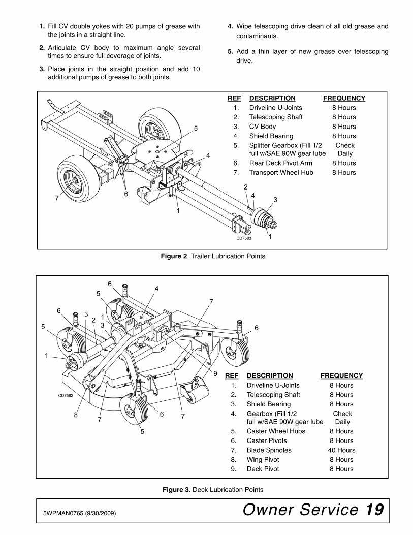
DECK ASSEMBLY . . . . . . . . . . . . . . . . . . . . . . . . . . . . . . . . . . . . 38 & 39
TRAILER FRAME ASSEMBLY . . . . . . . . . . . . . . . . . . . . . . . . . . . . . . . .40
GEARBOX ASSEMBLY. . . . . . . . . . . . . . . . . . . . . . . . . . . . . . . . . . . . . .41
BLADE & SPINDLE ASSEMBLY. . . . . . . . . . . . . . . . . . . . . . . . . . . . . . .42
WING DRIVE ASSEMBLY. . . . . . . . . . . . . . . . . . . . . . . . . . . . . . . . . . . .43
REAR DRIVE ASSEMBLY . . . . . . . . . . . . . . . . . . . . . . . . . . . . . . . . . . .44
CV DRIVE ASSEMBLY . . . . . . . . . . . . . . . . . . . . . . . . . . . . . . . . . . . . . .45
HUB & AXLE ASSEMBLY . . . . . . . . . . . . . . . . . . . . . . . . . . . . . . . . . . . .45
CASTER WHEEL ASSEMBLY . . . . . . . . . . . . . . . . . . . . . . . . . . . . . . . .46
HYDRAULIC CYLINDER. . . . . . . . . . . . . . . . . . . . . . . . . . . . . . . . . . . . .47
LIGHT KIT . . . . . . . . . . . . . . . . . . . . . . . . . . . . . . . . . . . . . . . . . . . . . . . .48
REAR CHAIN SHIELDING ASSEMBLY . . . . . . . . . . . . . . . . . . . . . . . . .49
HYDRAULIC LATCH RELEASE KIT (OPTIONAL) . . . . . . . . . . . . . . . . .49
MULCH KIT (OPTIONAL) . . . . . . . . . . . . . . . . . . . . . . . . . . . . . . . . . . . .50
(Rev. 8/6/2012)

36 Parts 5WPMAN0765 (9/30/2009)
MAIN FRAME ASSEMBLY
38 -
CO
MP
LET
E D
EC
AL
SE
T

Parts 375WPMAN0765 (9/30/2009)
MAIN FRAME ASSEMBLY PARTS LIST
REF PART QTY DESCRIPTION
1 ----- 1 Trailer assembly (see page 40)
2 ----- 1 Right deck assembly (see page 38)
3 ----- 1 Left deck assembly (see page 38)
4 ----- 1 Center deck assembly (see page 38)
5 5WP1029868 1 CV drive - 540 RPM (see page 45)
6 5WP1020903 2 Drive, Cmpl 40, 22.1 x 31.9(see page 43)
7 5WP1009508 1 Drive, Cmpl 40, 29.9 x 44.9(see page 44)
8 5WP1029481 2 Frame, wing deck lift
9 5WP1029495 2 Frame, wing deck link
10 5WP1029485 2 Frame, wing deck
11 5WP1029855 1 Frame, center deck
12 5WP1029493 2 Lock, wing cylinder
13 5WP1026530 1 Manual tube
14 5WP62484 1 SMV Socket
15 5WP1004251 1 SMV Bracket
16 5WP24611 1 SMV Emblem
17 5WP29547 1 Hydraulic cylinder 3 x 8 (see page 47)
18 5WP1019460 2 Hydraulic cylinder 3 x 10 (see page 47)
19 5WP1006400 1 Bulkhead fitting, 9/16 JICM x 1/4 NPTM
20 5WP1006401 1 Cross, 9/16 JICM x 1/4 NPTF
21 5WP1006402 2 Hose, 33"" x 9/16 JICF X 9/16 JICM
22 5WP1006403 1 Hose, 48"" x 9/16 JICF x 9/16 JICM
23 5WP1006404 1 Hose, 108"" x 9/16 JICF x 1/4 NPTM
24 5WP1006405 3 Elbow, 9/16 JICF x 1/2 NPTM 90°w/3/32 Restrictor
25 5WP8345 3 1 x 4.08 Headless pin
26 5WP8347 2 1 x 5.08 Headless pin
REF PART QTY DESCRIPTION
27 5WP38001 4 Pin, Wing hinge
28 5WP1029548 2 Pin, 1 x 5.03
29 5WP1029549 2 Pin, 1 x 9.09
30 * Pin, Safety 3/16
31 * 1/4 x 1-1/2 Cotter pin
32 5WP62440 2 Bumper Pad
33 5WP38295 3 Rope Clamp
34 5WP38257 3 S-Hook, .25 x 2.25
35 5WP1029853 1 Rope, .25 x 31.0
36 5WP38296 1 Rope, .25 x 95.0
37 5WP1016953 2 5/16 Chain - 11 link
38 5WP1029540 1 Complete decal set
39
40 * 1" Standard flat washer
41 * 1/4 NC x 1/2 Round head screw
42 * 1/4 NC Hex nut
43 * 5/16 NC x 3/4 Carriage bolt
44 * 5/16 NC Flange lock nut
45 * 5/16 NC x 1 HHCS GR5
46 * 1/2 NC x 1-1/2 HHCS GR5
47 * 1/2 NC x 3-1/2 HHCS GR5
48 * 1/2 Flat washer
49 * 1/2 NC Flange lock nut
50 * 5/8 NC x 5 HHCS
51 * 5/8 NC Flange lock nut
52 5WP12313 .625 x 1 x .789 HT Sleeve
53 5WP33647 6 Spacer, 3/4
54 * 1/4-28 Grease fitting
55 * 5/8 Standard flat washer
56 5WP8348 2 1 x 5.58 Headless pin
HHCS Hex Head Cap Screw
* Standard hardware, obtain locally
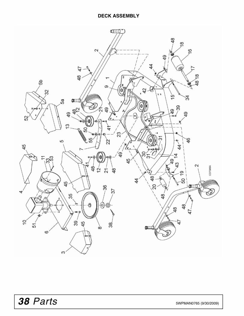
38 Parts 5WPMAN0765 (9/30/2009)
DECK ASSEMBLY

Parts 395WPMAN0765 (9/30/2009)
DECK ASSEMBLY PARTS LIST
REF PART QTY DESCRIPTION
1 ----- 1 54" Mower deck
2 ----- 2 Caster tube, Rear Deck (see page 46) - or -
2 ----- 2 Caster tube, Wing Deck (see page 46)
3 5WP1008022 1 Right shield
4 5WP1008023 1 Left shield
5 5WP1008024 1 Center shield, wing deck
5a 5WP1031170 1 Center shield, right half, rear deck
5b 5WP1031171 1 Center shield, left half, rear deck
6 5WP1008028 1 Gearbox stand
7 5WP1008044 1 Idler arm
8 5WP1008056 1 Gearbox sheave
9 ----- 3 Spindle (see page 42)
10 5WP1006649 1 Gearbox (see page 41)
11 5WP1002048 1 Shield, Rear Deck - or -
11 5WP1029547 1 Shield, Wing Deck
12 5WP67283 2 5" Idler
13 5WP67131 1 Spring
14 5WP1008181 1 Kit, Belt guide(includes items 30, 31, 44)
15 5WP1008034 1 Front roller bracket
16 5WP1006418 1 Front roller
17 5WP1006420 1 Spacer
18 5WP35193 2 Bearing
19 5WP1029861 2 Rear roller bracket
20 5WP1029865 2 Rear roller
21 5WP67284 2 Shoulder sleeve
REF PART QTY DESCRIPTION
22 5WP484 1 Sleeve .625 x 1.00 x .438
23 5WP20644 1 Belt
30 * 3/8 NC x 2 HHCS GR5
31 * 3/8 SAE Flat washer
32 * 3/8 Standard flat washer
33 * 5/16 Standard flat washer
34 5WP38107 1/2 NC x 9 HHCS GR5
35 * 1/4 x 1/4 x 1 Key
36 5WP20893 25 x 44 x 4 mm Flat washer
37 5WP51946 M24 x 2 Hex castle nut
38 * 3/16 x 2 Cotter pin
39 5WP19024 5/8 NC x 1-3/4 HFS GR5
41 * 1/2 NC x 1-3/4 HHCS GR5
42 * 3/8 NC x 1-1/4 Carriage bolt
43 * 3/8 NC x 1 Carriage bolt GR5
44 * 3/8 NC Flange lock nut
45 5WP62153 3/8 NC x 1 Hex flange serrated
46 5WP1008011 3/8 NC Square nut w/retainer
47 * 1/2 NC x 3-1/2 HHCS GR5
48 * 1/2 Flat washer
49 * 1/2 NC Flange lock nut
50 5WP12305 1/2 NC x 5-1/2 HHCS GR5
51 * 5/8 NC Flange lock nut
52 * 3/8 NC x 3/4 HHCS GR5
53 5WP39254 M8 x 1.25 x 16 mm HHCS
55 * 5/8 Standard flat washer
HFS Hex Flange Screw
HHCS Hex Head Cap Screw
* Standard hardware, obtain locally

40 Parts 5WPMAN0765 (9/30/2009)
TRAILER ASSEMBLY
REF PART QTY DESCRIPTION
1 ----- 1 Trailer frame
2 5WP1029501 1 Hitch
3 5WP1029518 1 Wing release
4 5WP1029529 1 Lock, rear deck
5 5WP23790 1 Parking jack
6 5WP40933 1 Gearbox, 4-Way Splitter
– – 5WP58815 2 Seal, Thru Shaft 4-Way Gr Box
– – 5WP58816 2 Seal, Wing Shaft 4-Way Gr Box
– – 5WP58817 6 Bearing, Cup & Cone 4-Way Box
– – 5WP1009083 1 Vent Plug & Washer
7 5WP44636 1 Shield, Gearbox 4-Way
8 5WP19407 1 Safety chain
9 5WP1001020 2 Wheel Hub & Axle (see page 45)
10 5WP1029854 2 Wheel & Tire, 20.0 x 8.8 x 8.0 (Turf)-or-
10 5WP38298G 2 Wheel & Tire 20.5 x 8.0 x 10 (Highway)
11 5WP21957 3 Spring, compression .58 x .08 x 2.4 40
12 5WP62626 4 Sleeve, .76 x 1.00 x 1.00
13 5WP1029542 1 Rope lever
27 5WP38001 1 Pin, Wing hinge
REF PART QTY DESCRIPTION
30 * Pin, Safety 3/16
31 * 3/8 NC x 3-1/2 HHCS GR5
32 * 3/8 Standard flat washer
33 * 3/8 NC Lock nut
34 * 1/2 NC x 3 HHCS GR5
35 * 1/2 NC x 1-1/4 HHCS GR5
36 * 1/2 NC x 2 HHCS GR5
37 * 1/2 NF x 1-1/8 Wheel bolt
38 5WP57811 1/2 Flat washer, extra thick hardened
39 * 5/8 NC x 5-1/2 HHCS GR5
40 5WP12005 5/8 NC x 6 HHCS GR5
41 5WP34467 .63 x 2.00 x .38 Flat washer
42 * 5/8 NC Lock nut
44 * 5/16 NC Flange lock nut
45 * 5/16 NC x 1 HHCS GR5
48 * 1/2 Flat washer
49 * 1/2 NC Flange lock nut
54 * 1/4-28 Grease fitting
HHCS Hex Head Cap Screw
* Standard hardware, obtain locally
(Rev. 6/25/2012)

Parts 415WPMAN0765 (9/30/2009)
GEARBOX ASSEMBLY
REF PART QTY DESCRIPTION
A 5WP1006649 Complete gearbox
1 5WP39275 1 Seal
2 5WP1007861 1 Snap ring
3 5WP1007865 1 Shim kit
4 5WP51850 1 Ball bearing
5 N/S 1 Input shaft
6 5WP20894 1 Key 8 x 10 x 30 mm
7 N/S 1 Input gear
8 5WP20890 3 Ball bearing
9 5WP1007864 1 Shim kit
10 5WP57466 1 Snap ring
11 5WP57374 1 Oil cap
12 N/S 1 Output shaft & gear
14 5WP1007866 1 Shim kit
15 5WP1007859 1 Snap ring
REF PART QTY DESCRIPTION
16 5WP1007858 1 Spacer
17 5WP1007862 1 Shim kit
18 5WP57466 1 Snap ring
19 5WP57463 1 Seal
21 5WP1007860 1 Snap ring
22 5WP20893 1 Washer 25 x 44 x 4 mm
23 5WP51946 1 Castle nut M24 x 2
24 * 1 3/16 x 2 Cotter pin
25 N/S* 1 3/8 Solid plug
26 N/S* 4 M10 x 22 mm HHCS
27 5WP39325 1 Vent plug
28 5WP1007873 1 Cover
29 5WP1007857 1 Spacer
HHCS Hex Head Cap Screw
* Standard hardware, obtain locally

42 Parts 5WPMAN0765 (9/30/2009)
BLADE & SPINDLE ASSEMBLY
REF PART QTY DESCRIPTION
A 5WP1009080 1 Complete spindle assembly(includes 1, 2, 4, 5 through 12, 14 & 15)
1 5WP64518 1 3/8 NF x 1 HHCS GR5
2 5WP70005 1 Cup washer
3 5WP1008059 1 Sheave
4 5WP1008055 1 Spacer
5 5WP72933 2 Spindle bearing
6 * 4 3/8 NC Flange locknut
7 * 1 1/4 Tapered grease fitting
8 5WP1008053 1 Spindle housing
9 * 4 3/8 NC x 1-1/2 HHCS GR5
10 5WP1008052 1 Spacer
11 * 1 Square key
12 5WP1008042 1 Shaft assembly
13 5WP78127KT 1 Blade kit, high suction 18.7"(includes 3 blades)
14 5WP10635 2 Cup washer
15 5WP1008095 1 5/8 NF x 2 HHCS GR5
HHCS Hex Head Cap Screw
* Standard hardware, obtain locally

Parts 435WPMAN0765 (9/30/2009)
WING DRIVELINE ASSEMBLY
REF PART QTY DESCRIPTION
A 5WP1020903 1 Complete driveline assembly
1 5WP1001300 2 Complete collar yoke C12 1-3/8 - 6
2 5WP38478 2 Cross and bearing kit
3 5WP1019442 1 Outer cone fix ring
4 5WP30922 6 Protection fixing screw
5 5WP1019444 1 Inner cone fix ring
9 5WP1001340 1 Lock collar repair kit
REF PART QTY DESCRIPTION
10 5WP1001302 1 Flexible pin
11 5WP1001301 1 Outer yoke tube
12 5WP1001305 1 Flexible pin
13 5WP1001306 1 Inner tube yoke
14 5WP1021554 1 Complete shield
15 5WP30926 1 Outer yoke & tube(must be cut to length)
16 5WP30932 1 Inner yoke & tube(must be cut to length)
44 Parts 5WPMAN0765 (9/30/2009)
REAR DRIVELINE ASSEMBLY
REF PART QTY DESCRIPTION
A 5WP1009508 1 Complete driveline assembly
1 5WP1001300 2 Complete collar yoke C12 1-3/8 - 6
2 5WP38478 2 Cross and bearing kit
3 5WP1019442 1 Outer cone fix ring
4 5WP30922 6 Protective fixing screw
5 5WP1019444 1 Inner cone fix ring
9 5WP1001340 1 Lock collar repair kit
10 5WP1001302 1 Flexible pin
REF PART QTY DESCRIPTION
11 5WP1001301 1 Outer yoke tube
12 5WP1001305 1 Flexible pin
13 5WP1001306 1 Inner tube yoke
14 5WP1021323 1 Complete shield
15 5WP30926 1 Outer yoke & tube(must be cut to length)
16 5WP30932 1 Inner yoke & tube(must be cut to length)

Parts 455WPMAN0765 (9/30/2009)
CV DRIVESHAFT ASSEMBLY
HUB & AXLE ASSEMBLY
REF PART QTY DESCRIPTION
A 5WP1029868 Complete driveline assembly
1 5WP19851 1 Slide lock repair kit
2 5WP1017362 1 Yoke, QD CV 1-3/8 - 6
3 5WP1017363 2 U-Joint repair kit 14CV
4 5WP1017364 1 CV Body w/fitting 14
5 5WP1017365 1 Yoke & shaft, CV splined 23.6
6 5WP1017366 1 Outer shield CV
7 5WP1024636 1 Drive shaft bearing kit
REF PART QTY DESCRIPTION
8 5WP18864 1 Decal, danger rotating driveline
9 5WP33347 1 Decal, danger guard missing
10 5WP1017367 1 Inner bearing kit
11 5WP1017368 1 Inner shield CV
12 5WP1017369 1 Yoke & tube 14R x 39.3
13 5WP154 1 U-Joint repair kit 14R
14 5WP53858 1 Yoke, 14 x 4.31 x 1.38 QD
15 5WP53857 1 Slide collar repair kit
REF PART QTY DESCRIPTION
1 5WP1001020 1 Wheel Hub & Axle Assembly
2 5WP1001021 1 Axle Shaft
3 5WP314 1 Seal, 1.50 x 2.44 x .31
4 5WP2303 2 Bearing, Cone
5 5WP38437 1 Wheel Hub, Housing w/Cups
6 5WP2305 2 Bearing, Cup
7 * 2 Washer, Flat 3/4 Standard
8 5WP5849 1 Nut, Slotted Hex 3/4 NF
9 * 1 Pin, Cotter 3/16 x 1
10 5WP14133 1 Hub Cap, Assembly w/Fitting
11 5WP531 1 Hub Cap
12 * 1 Grease Fitting, 1/4 Tapered Thread
* Standard hardware, obtain locally

46 Parts 5WPMAN0765 (9/30/2009)
CASTER WHEEL ASSEMBLY
REF PART QTY DESCRIPTION
1 5WP1029476 1 Caster Tube, Wing Deck
2 5WP1029850 1 Caster Tube, Rear Deck
3 5WP1008032 1 Caster yoke - rotating
4 5WP1029478 1 Caster yoke - non-rotating
5 5WP1008096 10 Wheel 10" solid (includes item 6)
6 5WP65578 20 Flanged bushing
7 5WP29368 10 Sleeve 1/2 x 3/4 x 3-3/8
8 5WP1029484 1 Sleeve, drilled .81x 1.25 x 7.34
9 5WP58999 1 Wear pad
10 5WP65130 3 or 6 1" Height spacer for rotating caster
REF PART QTY DESCRIPTION
11 5WP65129 1 or 3 1/2" Height spacer for rotating caster
12 5WP1029873 3 1" Height spacerfor non-rotating caster
13 5WP1029874 1 1/2" Height spacerfor non-rotating caster
14 5WP52855 3 1" Height spacer for post
15 5WP52853 1 1/2" Height spacer for post
16 5WP27542 2 7/16 Klik pin
17 5WP15134 1 .25 x 1.00 Spirol pin
18 * 1/2 NC x 5 HHCS GR5
19 * 1/2 NC Flange lock nut
20 * 1/4-28 Grease fitting
* Standard hardware, obtain locally

Parts 475WPMAN0765 (9/30/2009)
HYDRAULIC CYLINDER
Note: The center deck uses a 3 x 8 cylinder.
The wing decks use a 3 x 10 cylinder. Verifycylinder size before ordering replacementparts.
3 x 8 3 x 10
REF PART PART QTY DESCRIPTION
1 5WP29547 5WP1031166 Complete cylinder2 5WP19810 5WP19810 1 Seal repair kit (includes items 2A - 2G - or-2 5WP19810HD 5WP19810HD 1 Seal Kit with heavy duty piston seal
2A † † 1 Wiper seal2B † † 1 Rod seal
2C † † 1 Rod O-ring2D † † 2 Cap seal2E † † 2 Cap O-ring
2F † † 2 Piston seal2G † † 1 Piston O-ring3 N/S N/S 1 Cylinder housing - rod end
4 N/S N/S 1 Piston5 N/S N/S 1 Jam nut6 N/S N/S 4 Cylinder tie rod
7 * * 3 1/2 Pipe plug8 N/S N/S 1 Cylinder housing - butt end9 N/S N/S 2 Cylinder barrel
10 N/S N/S 8 Tie rod nut11 N/S N/S 1 Cylinder clevis12 N/S N/S 1 Cylinder rod
13 * * 1 Set screw 3/8 x 3/4 dog point1 Included in seal kit
* Standard hardware, obtain locallyN/S Not serviced

48 Parts 5WPMAN0765 (9/30/2009)
LIGHT KIT
REF PART QTY DESCRIPTION
A 5WD1031385 Light Kit
1 5WP90401149 1 Light, 4 Pin Right
2 5WP90401150 1 Light, 4 Pin Left
3 5WP1031386 2 Light Bracket
4 5WP1031388 2 Blank, .16 x 4.00 x 4.00
5 5WP1004479 1 Wire Harness
6 * 3/8 NC x 3-1/2 HHCS GR5
7 * 3/8 NC Flange Lock Nut
8 * 1/4 NC x 1 HHCS GR5
9 * 1/4 NC Lock Nut
10 * #10 x 1/2 Tapping Screw
11 * 34" Cable Tie
* Standard hardware, obtain locally
HHCS Hex Head Cap Screw

Parts 495WPMAN0765 (9/30/2009)
REAR CHAIN SHIELDING
HYDRAULIC RELEASE KIT (OPTIONAL)
REF PART QTY DESCRIPTION
A 5WD1008038 Chain shield assembly
1 5WP1007854 1 1/4 Pin
2 5WP4763 49 3-Link 1/4 proof chain
3 5WP1008037 1 Chain shield plate
4 5WP22086 5 Sleeve 1/2 x 3/4 x 1/2
5 * 5 3/8 NC x 1-1/4 Carriage bolt
6 * 5 3/8 NC Flanged locknut
* Standard hardware, obtain locally
REF PART QTY DESCRIPTION
A 5WD1029535 Latch release kit
1 5WP1029536 1 Release base
2 5WP1029537 1 Release slide
3 5WP29547 1 Hydraulic cylinder 3 x 8
4 5WP24512 2 Spring, extension 8-1/4
5 5WP8345 1 Pin, 1 x 4.08 headless
6 5WP8347 2 Pin, 1 x 5.08 headless
7 * Cotter pin, 1/4 x 1-1/2
8 5WP11893 1 Bushing, Pipe Reducing 1/2 x 1/4
9 5WP10290 1 Elbow, 90 Deg 3/32 Rstr 1/4 x 1/4
10 5WP17628 1 Hose, HP 1/4 NPT x 108
11 5WP11975 1 1/2 NPT Vent plug
12 * 1" Standard flat washer
13 5WP11920 2 Washer, 1 x 1-7/8 x 1/4
* Standard hardware, obtain locally

50 Parts 5WPMAN0765 (9/30/2009)
MULCH KIT (OPTIONAL)
REF PART QTY DESCRIPTION
A 5WD1029530 Mulch Kit, 54" deck
1 5WP75106 2 Support bracket,bent link .14 x 1.0 x 3.88
2 * 5/16 NC x 3/4 Carriage bolt GR5
3 * 5/16 NC Flange lock nut
4 * 3/8 NC x 1 Carriage bolt GR5
5 * 3/8 NC Flange lock nut
* Standard hardware, obtain locally

Parts 515WPMAN0765 (9/30/2009)
NOTES

52 Appendix Bolt Torque & Size Charts (Rev. 3/28/2007)
BOLT TORQUE CHARTAlways tighten hardware to these values unless a different torque value or tightening procedure is listed for a specific application.Fasteners must always be replaced with the same grade as specified in the manual parts list.Always use the proper tool for tightening hardware: SAE for SAE hardware and Metric for metric hardware.Make sure fastener threads are clean and you start thread engagement properly. All torque values are given to specifications used on hardware defined by SAE J1701 MAR 99 & J1701M JUL 96.
Diameter (Inches)
WrenchSize
MARKING ON HEAD
SAE 2 SAE 5 SAE 8
lbs-ft N-m lbs-ft N-m lbs-ft N-m
1/4" 7/16" 6 8 10 13 14 18
5/16" 1/2" 12 17 19 26 27 37
3/8" 9/16" 23 31 35 47 49 67
7/16" 5/8" 36 48 55 75 78 106
1/2" 3/4" 55 75 85 115 120 163
9/16" 13/16" 78 106 121 164 171 232
5/8" 15/16" 110 149 170 230 240 325
3/4" 1-1/8" 192 261 297 403 420 569
7/8" 1-5/16" 306 416 474 642 669 907
1" 1-1/2" 467 634 722 979 1020 1383
Diameter & Thread Pitch (Millimeters)
Wrench Size
COARSE THREAD FINE THREAD
Diameter & Thread Pitch (Millimeters)
MARKING ON HEAD MARKING ON HEAD
Metric 8.8 Metric 10.9 Metric 8.8 Metric 10.9
N-m lbs-ft N-m lbs-ft N-m lbs-ft N-m lbs-ft
6 x 1.0 10 mm 8 6 11 8 8 6 11 8 6 x 1.0
8 x 1.25 13 mm 20 15 27 20 21 16 29 22 8 x 1.0
10 x 1.5 16 mm 39 29 54 40 41 30 57 42 10 x 1.25
12 x 1.75 18 mm 68 50 94 70 75 55 103 76 12 x 1.25
14 x 2.0 21 mm 109 80 151 111 118 87 163 120 14 x 1.5
16 x 2.0 24 mm 169 125 234 173 181 133 250 184 16 x 1.5
18 x 2.5 27 mm 234 172 323 239 263 194 363 268 18 x 1.5
20 x 2.5 30 mm 330 244 457 337 367 270 507 374 20 x 1.5
22 x 2.5 34 mm 451 332 623 460 495 365 684 505 22 x 1.5
24 x 3.0 36 mm 571 421 790 583 623 459 861 635 24 x 2.0
30 x 3.0 46 mm 1175 867 1626 1199 1258 928 1740 1283 30 x 2.0
A
SAE SERIES TORQUE CHART
SAE Bolt Head Identification
SAE Grade 2(No Dashes)
SAE Grade 5(3 Radial Dashes)
SAE Grade 8(6 Radial Dashes)
A
METRIC SERIES TORQUE CHART
Metric Bolt Head Identification
8.8
MetricGrade 10.9
10.9
MetricGrade 8.8
A
A A
Typical Washer Installations Lock Washer
Flat Washer
8/9/00
Bolt

Appendix 53Bolt Torque & Size Charts (Rev. 3/28/2007)
BOLT SIZE CHARTNOTE: Chart shows bolt thread sizes and corresponding head (wrench) sizes for standard SAE and metric bolts.
ABBREVIATIONSAG .............................................................. AgricultureASABE.................... American Society of Agricultural &
Biological Engineers (formerly ASAE)ASAE ....... American Society of Agricultural EngineersATF ............................... Automatic Transmission FluidBSPP .............................British Standard Pipe ParallelBSPTM ................British Standard Pipe Tapered MaleCV.....................................................Constant VelocityCCW .............................................. Counter-ClockwiseCW............................................................... ClockwiseF ...................................................................... FemaleFT .............................................................. Full ThreadGA .................................................................... GaugeGR (5, etc.) ........................................... Grade (5, etc.)HHCS ........................................Hex Head Cap ScrewHT........................................................... Heat-TreatedJIC .................Joint Industry Council 37° Degree FlareLH .................................................................Left HandLT........................................................................... Leftm......................................................................... Metermm................................................................MillimeterM.......................................................................... Male
MPa.........................................................Mega Pascal
N.......................................................................Newton
NC ......................................................National Coarse
NF ...........................................................National Fine
NPSM.....................National Pipe Straight Mechanical
NPT .......................................... National Pipe Tapered
NPT SWF .........National Pipe Tapered Swivel Female
ORBM .......................................... O-Ring Boss - Male
P...........................................................................Pitch
PBY ...................................................... Power-Beyond
psi..........................................Pounds per Square Inch
PTO..................................................... Power Take Off
QD....................................................Quick Disconnect
RH ..............................................................Right Hand
ROPS ........................... Roll-Over Protective Structure
RPM ........................................Revolutions Per Minute
RT ....................................................................... Right
SAE ..........................Society of Automotive Engineers
UNC .....................................................Unified Coarse
UNF...........................................................Unified Fine
UNS......................................................Unified Special
5/16 3/8 1/2 5/8 3/4 7/8SAE Bolt Thread Sizes
MM 25 50 75 100 125 150 175
IN 1 7
Metric Bolt Thread Sizes8MM 18MM14MM12MM10MM 16MM
2 3 4 5 6

54 Index 5WPMAN0765 (9/30/2009)
INDEX
ADJUSTMENTSCutting Height 14Leveling Mower 14
ASSEMBLYDealer Set-Up Instructions 30Light Kit 32Optional Equipment
Hydraulic Latch Release Installation 30Mulch Kit Installation 31
DEALER CHECK LISTDelivery Check (Dealer’s Responsibility) 33Pre-Delivery Check List(Dealer’s Responsibility) 33
DEALER SERVICEBlade Spindle
Assemble Spindle 24Disassemble Spindle 24Remove Spindle 24Repair 24
GearboxAssemble 26Disassemble 26Install 28Remove 26Repair 25Seal Installation 25Seal Replacement 25Vertical Shaft Repair 25
Install Drive Sheave 28Universal Joint
Assembly 29Disassembly 28Repair 28
GENERALAbbreviations 53Bolt Size Chart 53Bolt Torque Chart 52General Information 4Introduction 2Obtaining Replacement Manuals 2Product Registration 2
Specifications 3Table of Contents 3
OPERATIONAdjustment
Cutting Height Chart 14Attaching Mower to Tractor 13
Attaching Hydraulic Hoses 14Check List
Pre-Operation (Owners Responsibility) 17Cutting Height Adjustment 14CV Driveline Turning Limits 14Leveling Mower 14Operating 15
On Uneven Terrain 16Technique 16Tips 16
Removing Mower from Tractor 16Start and Stop Mower 15Starting and Stopping Mower 15Transport 15
OWNER SERVICEClean Cutter
After Each Use 22Periodically or Before Extended Storage 22
LubricationInformation 18, 19
PARTSParts Index 35
SAFETYCheck List
Delivery Check List (Dealer’s Responsibility) 33Pre-Delivery Check List(Dealer’s Responsibility) 33Pre-Operation (Owner’s Responsibility) 17
Safety Decals 9Safety Rules 5Safety Symbols Explained 2
TROUBLE SHOOTINGBelt Conditions 23Mowing Conditions 22

Index 555WPMAN0765 (9/30/2009)
NOTES

©2002 Woods Equipment Company. All rights reserved. WOODS and the Woods logo are trademarks of Woods Equipment Company. FrontierEquipment and the Frontier logo are trademarks of Deere & Company. All other trademarks, trade names, or service marks that appear in thismanual are the property of their respective companies or mark holders. Specifications subject to change without notice.
PART NUMBER
5WPMAN0765