Embed Size (px)
Citation preview
� �FM 352 electronic cam controller
___________________
___________________
___________________
___________________
___________________
___________________
___________________
___________________
___________________
___________________
___________________
___________________
___________________
___________________
___________________
___________________
___________________
SIMATIC
S7-300 FM 352 electronic cam controller
Operating Instructions
05/2011 A5E01071724-03
Preface 1
Product overview 2
Cam control basics 3
Installing and removing the FM 352
4
Wiring the FM 352 5
Installing the software 6
Programming the FM 352 7
Commissioning the FM 352 8
Machine and cam data 9
Settings 10
Encoders 11
Diagnostics 12
Examples 13
Technical data A
Connection Diagrams B
Data blocks / error lists C
Programming without SFB 52 and SFB 53
D
Legal information
Legal information Warning notice system
This manual contains notices you have to observe in order to ensure your personal safety, as well as to prevent damage to property. The notices referring to your personal safety are highlighted in the manual by a safety alert symbol, notices referring only to property damage have no safety alert symbol. These notices shown below are graded according to the degree of danger.
DANGER indicates that death or severe personal injury will result if proper precautions are not taken.
WARNING indicates that death or severe personal injury may result if proper precautions are not taken.
CAUTION with a safety alert symbol, indicates that minor personal injury can result if proper precautions are not taken.
CAUTION without a safety alert symbol, indicates that property damage can result if proper precautions are not taken.
NOTICE indicates that an unintended result or situation can occur if the relevant information is not taken into account.
If more than one degree of danger is present, the warning notice representing the highest degree of danger will be used. A notice warning of injury to persons with a safety alert symbol may also include a warning relating to property damage.
Qualified Personnel The product/system described in this documentation may be operated only by personnel qualified for the specific task in accordance with the relevant documentation, in particular its warning notices and safety instructions. Qualified personnel are those who, based on their training and experience, are capable of identifying risks and avoiding potential hazards when working with these products/systems.
Proper use of Siemens products Note the following:
WARNING Siemens products may only be used for the applications described in the catalog and in the relevant technical documentation. If products and components from other manufacturers are used, these must be recommended or approved by Siemens. Proper transport, storage, installation, assembly, commissioning, operation and maintenance are required to ensure that the products operate safely and without any problems. The permissible ambient conditions must be complied with. The information in the relevant documentation must be observed.
Trademarks All names identified by ® are registered trademarks of Siemens AG. The remaining trademarks in this publication may be trademarks whose use by third parties for their own purposes could violate the rights of the owner.
Disclaimer of Liability We have reviewed the contents of this publication to ensure consistency with the hardware and software described. Since variance cannot be precluded entirely, we cannot guarantee full consistency. However, the information in this publication is reviewed regularly and any necessary corrections are included in subsequent editions.
Siemens AG Industry Sector Postfach 48 48 90026 NÜRNBERG GERMANY
A5E01071724-03 Ⓟ 06/2011
Copyright © Siemens AG 2011. Technical data subject to change
FM 352 electronic cam controller Operating Instructions, 05/2011, A5E01071724-03 3
Table of contents
1 Preface ...................................................................................................................................................... 7
2 Product overview ..................................................................................................................................... 11
2.1 The FM 352..................................................................................................................................11
2.2 Fields of application of FM 352....................................................................................................12
2.3 Configuration of an electronic cam control with FM 352..............................................................13
3 Cam control basics .................................................................................................................................. 15
3.1 Properties of the cam types .........................................................................................................15
3.2 Tracks and track result.................................................................................................................18 3.2.1 Standard tracks............................................................................................................................18 3.2.2 Special tracks...............................................................................................................................20
3.3 Hysteresis ....................................................................................................................................22
3.4 Dynamic adjustment ....................................................................................................................24
3.5 Interfaces of the cam controller....................................................................................................25
4 Installing and removing the FM 352......................................................................................................... 27
5 Wiring the FM 352 ................................................................................................................................... 29
5.1 Before you start wiring .................................................................................................................29
5.2 Description of the encoder interface ............................................................................................30
5.3 Connecting the encoder...............................................................................................................31
5.4 Terminal assignment of the front connector ................................................................................32
5.5 Wiring the front connector............................................................................................................34
6 Installing the software .............................................................................................................................. 37
7 Programming the FM 352 ........................................................................................................................ 39
7.1 Basics of Programming an FM 352 .............................................................................................40
7.2 FC CAM_INIT (FC 0) ...................................................................................................................42
7.3 FB CAM_CTRL (FB 1) .................................................................................................................43
7.4 FB CAM_DIAG (FB 2)..................................................................................................................47
7.5 Data blocks ..................................................................................................................................49 7.5.1 Templates for data blocks............................................................................................................49 7.5.2 Channel DB..................................................................................................................................49 7.5.3 Diagnostic DB ..............................................................................................................................50 7.5.4 Parameter DB ..............................................................................................................................51
Table of contents
FM 352 electronic cam controller 4 Operating Instructions, 05/2011, A5E01071724-03
7.6 Interrupts ..................................................................................................................................... 52
7.7 Evaluation of a hardware interrupt .............................................................................................. 53
7.8 Evaluating a diagnostics interrupt ............................................................................................... 54
7.9 Technical data............................................................................................................................. 55
7.10 High-speed access to module data............................................................................................. 56
7.11 Parameter transmission paths .................................................................................................... 58
8 Commissioning the FM 352 ..................................................................................................................... 61
9 Machine and cam data ............................................................................................................................ 67
9.1 Machine and cam data................................................................................................................ 67
9.2 Writing and enabling machine data............................................................................................. 68
9.3 Read machine data ..................................................................................................................... 70
9.4 Writing cam data ......................................................................................................................... 71
9.5 Reading cam data ....................................................................................................................... 72
9.6 Physical units system.................................................................................................................. 73
9.7 Machine data of the axis ............................................................................................................. 75
9.8 Determining the correct absolute encoder adjustment ............................................................... 82
9.9 Example: Adjusting the absolute encoder................................................................................... 84
9.10 Machine data of the encoder ...................................................................................................... 86
9.11 Resolution ................................................................................................................................... 91
9.12 Quantity framework and track data ............................................................................................. 94
9.13 Interrupt enable ........................................................................................................................... 96
9.14 Cam data..................................................................................................................................... 97
10 Settings.................................................................................................................................................. 103
10.1 Influence of settings on the switching characteristics of time-based cams .............................. 103
10.2 Set Actual Value/Set Actual Value on-the-fly/Cancel Set Actual Value.................................... 104
10.3 Set zero offset ........................................................................................................................... 107
10.4 Set reference point.................................................................................................................... 110
10.5 Change cam edges ................................................................................................................... 112
10.6 Perform "Fast Cam Parameter Change"................................................................................... 114
10.7 Executing "Length measurement and edge detection"............................................................. 116
10.8 Retrigger reference point .......................................................................................................... 120
10.9 Disabling software limit switches .............................................................................................. 124
Table of contents
FM 352 electronic cam controller Operating Instructions, 05/2011, A5E01071724-03 5
10.10 Simulating ..................................................................................................................................126
10.11 Read "count values of counter cam tracks" ...............................................................................128
10.12 Read "position and track data"...................................................................................................130
10.13 Read encoder data ....................................................................................................................131
10.14 Read cam and track data...........................................................................................................132
10.15 Setting control signals for the cam controller.............................................................................133
10.16 Querying checkback signals for the cam controller ...................................................................134
10.17 Setting the return signals for diagnostics...................................................................................135
11 Encoders ............................................................................................................................................... 137
11.1 Incremental encoders ................................................................................................................137
11.2 Proximity switches .....................................................................................................................140
11.3 Absolute encoder .......................................................................................................................141
12 Diagnostics ............................................................................................................................................ 145
12.1 Possibilities for error evaluation.................................................................................................145
12.2 Meaning of the error LEDs.........................................................................................................146
12.3 Diagnostic interrupts ..................................................................................................................147 12.3.1 Enable diagnostic interrupts.......................................................................................................147 12.3.2 Reaction of FM 352 to errors with diagnostics interrupt ............................................................148
13 Examples............................................................................................................................................... 151
13.1 Introduction ................................................................................................................................151
13.2 Requirements.............................................................................................................................152
13.3 Preparing the examples .............................................................................................................153
13.4 Displaying the code of the examples .........................................................................................153
13.5 Testing the example...................................................................................................................154
13.6 Reusing an example project ......................................................................................................154
13.7 Sample program 1 "Getting Started"..........................................................................................155
13.8 Sample Program 2 "Commissioning".........................................................................................156
13.9 Sample program 3 "One Module" ..............................................................................................157
13.10 Sample program 4 "Interrupts"...................................................................................................160
13.11 Sample program 5 "MultiModules".............................................................................................162
Table of contents
FM 352 electronic cam controller 6 Operating Instructions, 05/2011, A5E01071724-03
A Technical data ....................................................................................................................................... 165
A.1 General technical data .............................................................................................................. 165
A.2 Technical data........................................................................................................................... 166
B Connection Diagrams ............................................................................................................................ 169
B.1 Encoder types ........................................................................................................................... 169
B.2 Connection Diagram for Incremental Encoder Siemens 6FX 2001-2 (Up=5V; RS 422) .......... 170
B.3 Connection Diagram for Incremental Encoder Siemens 6FX 2001-2 (Up=24V; RS 422) ........ 172
B.4 Wiring Diagram of the Incremental Encoder Siemens 6FX 2001-4 (Up = 24 V; HTL) ............. 174
B.5 Connection Diagram for Absolute Encoder Siemens 6FX 2001-5 (Up=24V; SSI) ................... 176
C Data blocks / error lists .......................................................................................................................... 177
C.1 Content of the channel DB........................................................................................................ 177
C.2 Content of the parameter DB .................................................................................................... 185
C.3 Data and Structure of the Diagnostic DB.................................................................................. 187
C.4 Error classes ............................................................................................................................. 190
D Programming without SFB 52 and SFB 53 ............................................................................................ 199
D.1 Overview of the Programming without SFB 52 and SFB 53 section ........................................ 199
D.2 Basics of Programming an FM 352........................................................................................... 200
D.3 FC CAM_INIT (FC 0)................................................................................................................. 201
D.4 FC CAM_CTRL (FC 1) .............................................................................................................. 202
D.5 FC CAM_DIAG (FC 2)............................................................................................................... 206
D.6 Data blocks ............................................................................................................................... 208 D.6.1 Templates for data blocks ......................................................................................................... 208 D.6.2 Channel DB............................................................................................................................... 208 D.6.3 Diagnostics DB.......................................................................................................................... 209 D.6.4 Parameter DB ........................................................................................................................... 210
D.7 Interrupts ................................................................................................................................... 211
D.8 Evaluation of a hardware interrupt ............................................................................................ 212
D.9 Evaluating a diagnostics interrupt ............................................................................................. 213
D.10 Technical specifications ............................................................................................................ 214
D.11 Fast access to module data ...................................................................................................... 215
D.12 Parameter transfer routes ......................................................................................................... 217
Index...................................................................................................................................................... 219
FM 352 electronic cam controller Operating Instructions, 05/2011, A5E01071724-03 7
Preface 1
Purpose of the manual This manual gives you a complete overview of the FM 352 function module. It helps you during installation and commissioning. The procedures involved in installation, wiring, parameter assignment, and programming are described.
This manual is intended for the programmers of STEP 7 programs and for those responsible for configuring, commissioning, and servicing automation systems.
Basic knowledge required This manual presumes general knowledge in the field of automation engineering.
In addition, you should know how to use computers or devices with similar functions (e.g., programming devices) under the Microsoft® Windows® operating systems and have a knowledge of STEP 7 programming.
Scope of the manual This manual contains the description of the FM 352 electronic cam controller as valid at the time it was published. We reserve the right to publish modifications of FM 352 functionality in a separate Product Information.
The manual with the number in the footer applies to the FM 352 with order number
EWA 4NEB 720 6004–01 6ES7 352-1AH00-0AE0 EWA 4NEB 720 6004–01 a 6ES7 352-1AH01-0AE0 C79000–G7000–C352–03 6ES7 352-1AH01-0AE0 A5E01071724-01 6ES7 352-1AH01-0AE0 A5E01071724-02 6ES7 352-1AH02-0AE0 A5E01071719-03 6ES7 352-1AH02-0AE0
Content of this manual This manual describes the hardware and software of the FM 352 electronic cam controller.
It comprises the following sections:
● Fundamentals part (Chapters 1 to 8)
● Reference part (Chapters 9 to 13)
● Appendices (A, B, C, and D)
● Index
Preface
FM 352 electronic cam controller 8 Operating Instructions, 05/2011, A5E01071724-03
Standards The SIMATIC S7-300 product series is compliant with IEC 61131-2.
Recycling and disposal The FM 352 is low in contaminants and can therefore be recycled. For ecologically compatible recycling and disposal of your old device, contact a certificated disposal service for electronic scrap.
Additional support If you have any further questions about the use of products described in this manual and do not find the right answers here, contact your local Siemens representative (http://www.siemens.com/automation/partner):
A guide to the technical documentation for the various products and systems is available on the Internet:
● SIMATIC Guide manuals (http://www.siemens.com/simatic-tech-doku-portal)
The online catalog and online ordering systems are also available on the Internet:
● A&D Mall (http://www.siemens.com/automation/mall)
Training center To help you get started with automation technology and systems, we offer a variety of courses. Contact your regional Training Center or the central Training Center in D-90327 Nuremberg, Germany.
● Internet: SITRAIN homepage (http://www.sitrain.com)

Preface
FM 352 electronic cam controller Operating Instructions, 05/2011, A5E01071724-03 9
Technical Support You can access technical support for all A&D projects via the following:
● Online support request form: (http://www.siemens.com/automation/support-request)
Service & Support on the Internet In addition to our documentation, we offer a comprehensive online knowledge base on the Internet at:
Industry Automation and Drive Technologies - Homepage (http://www.siemens.com/automation/service&support)
There you will find the following information, for example:
● The newsletter that provides up-to-date information on your products.
● The documents you need via our Search function in Service & Support.
● A forum for global information exchange by users and specialists.
● Your local partner for Automation and Drives.
● Information about on-site service, repairs, and spare parts. Much more can be found under "Services".

Preface
FM 352 electronic cam controller 10 Operating Instructions, 05/2011, A5E01071724-03
FM 352 electronic cam controller Operating Instructions, 05/2011, A5E01071724-03 11
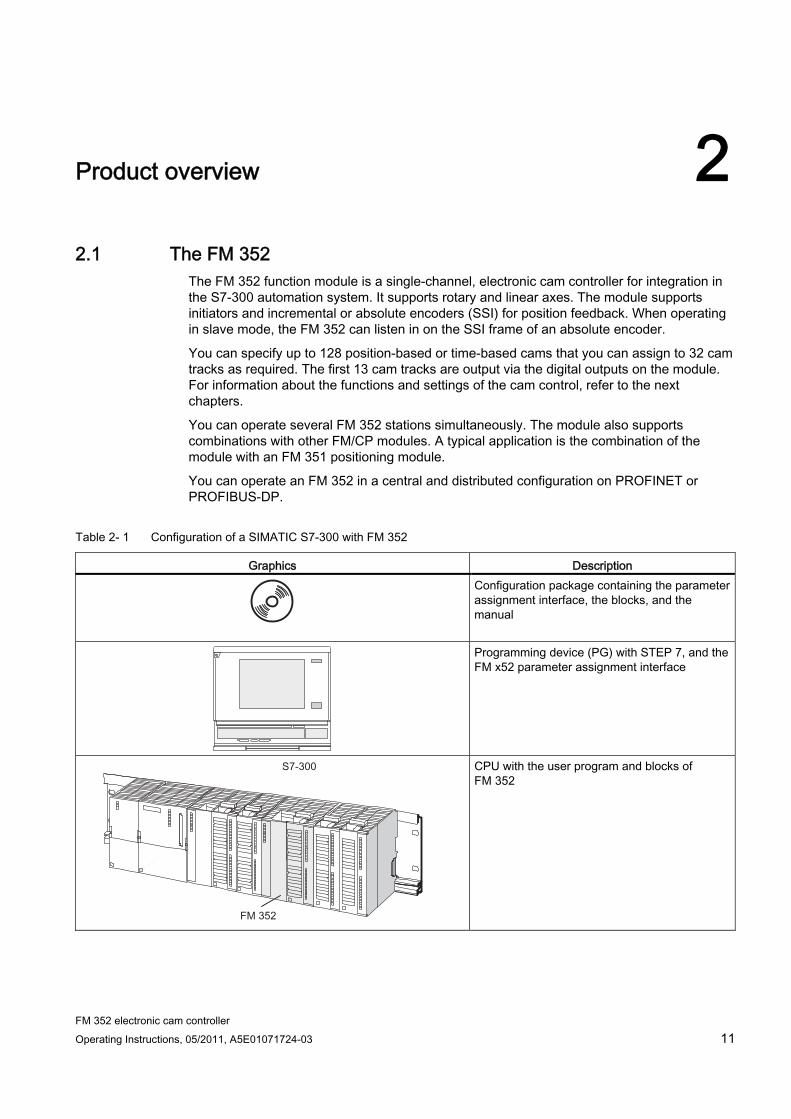
Product overview 22.1 The FM 352
The FM 352 function module is a single-channel, electronic cam controller for integration in the S7-300 automation system. It supports rotary and linear axes. The module supports initiators and incremental or absolute encoders (SSI) for position feedback. When operating in slave mode, the FM 352 can listen in on the SSI frame of an absolute encoder.
You can specify up to 128 position-based or time-based cams that you can assign to 32 cam tracks as required. The first 13 cam tracks are output via the digital outputs on the module. For information about the functions and settings of the cam control, refer to the next chapters.
You can operate several FM 352 stations simultaneously. The module also supports combinations with other FM/CP modules. A typical application is the combination of the module with an FM 351 positioning module.
You can operate an FM 352 in a central and distributed configuration on PROFINET or PROFIBUS-DP.
Table 2- 1 Configuration of a SIMATIC S7-300 with FM 352
Graphics Description
Configuration package containing the parameter assignment interface, the blocks, and the manual
Programming device (PG) with STEP 7, and the FM x52 parameter assignment interface
CPU with the user program and blocks of FM 352
Product overview 2.2 Fields of application of FM 352
FM 352 electronic cam controller 12 Operating Instructions, 05/2011, A5E01071724-03
2.2 Fields of application of FM 352
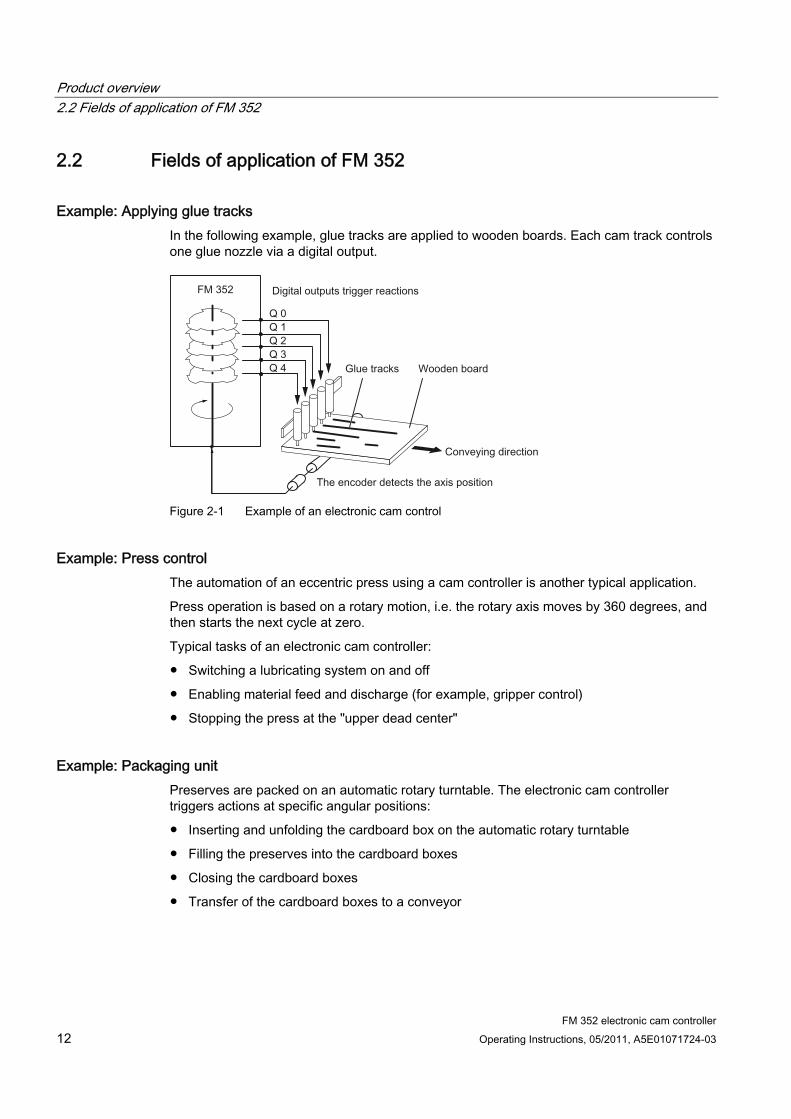
Example: Applying glue tracks In the following example, glue tracks are applied to wooden boards. Each cam track controls one glue nozzle via a digital output.
Figure 2-1 Example of an electronic cam control
Example: Press control The automation of an eccentric press using a cam controller is another typical application.
Press operation is based on a rotary motion, i.e. the rotary axis moves by 360 degrees, and then starts the next cycle at zero.
Typical tasks of an electronic cam controller:
● Switching a lubricating system on and off
● Enabling material feed and discharge (for example, gripper control)
● Stopping the press at the "upper dead center"
Example: Packaging unit Preserves are packed on an automatic rotary turntable. The electronic cam controller triggers actions at specific angular positions:
● Inserting and unfolding the cardboard box on the automatic rotary turntable
● Filling the preserves into the cardboard boxes
● Closing the cardboard boxes
● Transfer of the cardboard boxes to a conveyor
Product overview 2.3 Configuration of an electronic cam control with FM 352
FM 352 electronic cam controller Operating Instructions, 05/2011, A5E01071724-03 13
2.3 Configuration of an electronic cam control with FM 352
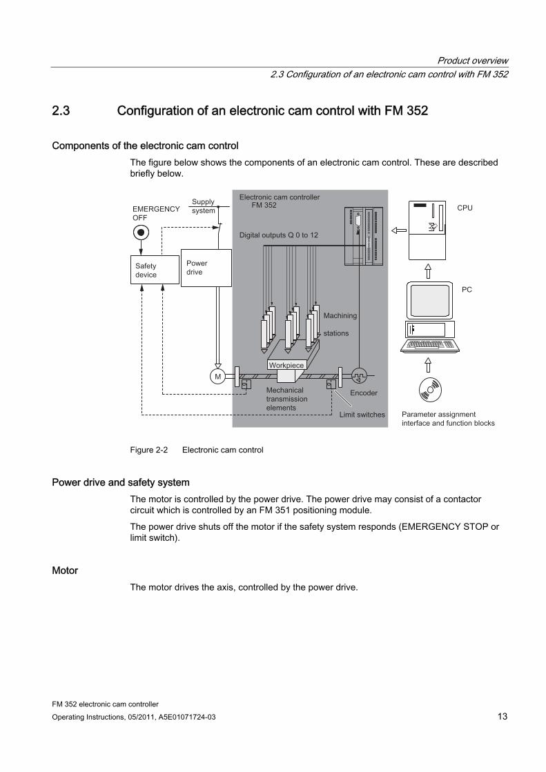
Components of the electronic cam control The figure below shows the components of an electronic cam control. These are described briefly below.
Figure 2-2 Electronic cam control
Power drive and safety system The motor is controlled by the power drive. The power drive may consist of a contactor circuit which is controlled by an FM 351 positioning module.
The power drive shuts off the motor if the safety system responds (EMERGENCY STOP or limit switch).
Motor The motor drives the axis, controlled by the power drive.
Product overview 2.3 Configuration of an electronic cam control with FM 352
FM 352 electronic cam controller 14 Operating Instructions, 05/2011, A5E01071724-03
FM 352 electronic cam controller The electronic cam controller determines the actual position value of the axis based on an encoder signal. It evaluates the encoder signals (for example, by counting the pulses) which are proportional to the distance traveled. Based on the actual position value, it sets or resets the digital outputs ("cams"). The processing stations are controlled by signals at the digital outputs.
Encoder The encoder returns position and direction data.
CPU The CPU executes the user program. The user program and the module exchange data and signals by means of function calls.
PG/PC The electronic cam controller is programmed and assigned its parameters using a PG or PC.
● Assigning parameters: You assign parameters for the FM 352 using the parameter assignment interface or the parameter DB.
● Assigning parameters: You program FM 352 functions you can implement directly in the user program.
● Testing and commissioning: You test and commission the FM 352 with the help of the parameter assignment interface.
FM 352 electronic cam controller Operating Instructions, 05/2011, A5E01071724-03 15
Cam control basics 33.1 Properties of the cam types
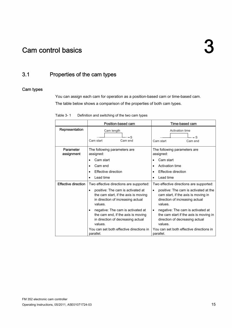
Cam types You can assign each cam for operation as a position-based cam or time-based cam.
The table below shows a comparison of the properties of both cam types.
Table 3- 1 Definition and switching of the two cam types
Position-based cam Time-based cam Representation
Parameter assignment
The following parameters are assigned: Cam start Cam end Effective direction Lead time
The following parameters are assigned: Cam start Activation time Effective direction Lead time
Effective direction Two effective directions are supported: positive: The cam is activated at
the cam start, if the axis is moving in direction of increasing actual values.
negative: The cam is activated at the cam end, if the axis is moving in direction of decreasing actual values.
You can set both effective directions in parallel.
Two effective directions are supported: positive: The cam is activated at the
cam start, if the axis is moving in direction of increasing actual values.
negative: The cam is activated at the cam start if the axis is moving in direction of decreasing actual values.
You can set both effective directions in parallel.

Cam control basics 3.1 Properties of the cam types
FM 352 electronic cam controller 16 Operating Instructions, 05/2011, A5E01071724-03
Position-based cam Time-based cam Enabling The cam is activated:
at the cam start, if the axis is moving in positive direction and positive effective direction is set.
at the cam end, if the axis is moving in negative direction and negative effective direction is set.
when the actual value lies within the cam range.
The cam is activated: at the cam start, if the axis is
moving in positive direction, and a positive effective direction is set.
at the cam start, if the axis is moving in negative direction, and a negative effective direction is set.
After it has been activated, the full cam activation time elapses, even if the direction of motion of the axis changes after the cam is activated. The cam is not retriggered if its start position is passed once again within the cam activation time.
Deactivating The cam is deactivated if: the assigned distance has been
traveled axis motion in reversed effective
direction is detected, and hysteresis is not assigned
axis motion in reversed effective direction is detected, and the hysteresis is exited
the actual value no longer lies within the cam range, e.g., "Set actual value"/"Set actual value on-the-fly".
The cam is deactivated on expiration of the assigned time, i.e., the activation time is not restarted.
Path length The path length of the cam is defined by the cam start and cam end. The cam start and cam end belong to the active section of the cam.
The path length of the cam is determined by the axis velocity within the cam activation time.
On period The on period of the cam is determined by the speed at which the axis travels across the path length of the cam.
The on period of the cam is assigned with the activation time.
Direction detection The direction of the axis motion is determined as follows:
● At each pulse of the incremental encoder.
● With each error-free frame of an SSI encoder.
Cam control basics 3.1 Properties of the cam types
FM 352 electronic cam controller Operating Instructions, 05/2011, A5E01071724-03 17
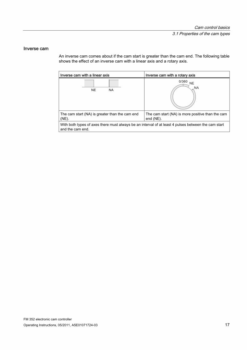
Inverse cam An inverse cam comes about if the cam start is greater than the cam end. The following table shows the effect of an inverse cam with a linear axis and a rotary axis.
Inverse cam with a linear axis Inverse cam with a rotary axis
The cam start (NA) is greater than the cam end (NE).
The cam start (NA) is more positive than the cam end (NE).
With both types of axes there must always be an interval of at least 4 pulses between the cam start and the cam end.
Cam control basics 3.2 Tracks and track result
FM 352 electronic cam controller 18 Operating Instructions, 05/2011, A5E01071724-03
3.2 Tracks and track result
3.2.1 Standard tracks
Cam tracks The 32 tracks can be used to control up to 32 different switching actions. You can evaluate the tracks based on the checkback signals.
The first 13 tracks (track 0 to 12) are each assigned a digital output (Q0 to Q12) of FM 352. Those tracks can be used for the direct control of a connected contactor relay, for example.
Track result The system provides up to 128 cams which can be assigned to user-specific tracks.
Each track can be assigned several cams. The track result is a logic OR operation derived from all cam values of this track.
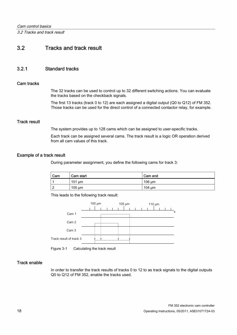
Example of a track result During parameter assignment, you define the following cams for track 3:
Cam Cam start Cam end 1 101 µm 106 µm 2 100 µm 104 µm
This leads to the following track result:
Figure 3-1 Calculating the track result
Track enable In order to transfer the track results of tracks 0 to 12 to as track signals to the digital outputs Q0 to Q12 of FM 352, enable the tracks used.
Cam control basics 3.2 Tracks and track result
FM 352 electronic cam controller Operating Instructions, 05/2011, A5E01071724-03 19
External enable of track 3 You can assign an external enable signal for track 3 in the machine data. Track signal 3 is then logically linked to digital input I3 by an AND operation, before it can switch digital output Q3 of the FM 352.
Digital output Q3 is thus only set if the following conditions are satisfied:
● The corresponding track is enabled.
● At least one cam on this track is active (track result = 1).
● The corresponding digital input I3 was set by an external event.
Setting the track signals The track signals 0 to 12 (according to digital outputs Q0 to Q12) can be set by the cam control system, or by the CPU.
Cam control basics 3.2 Tracks and track result
FM 352 electronic cam controller 20 Operating Instructions, 05/2011, A5E01071724-03
3.2.2 Special tracks
Definition You can program tracks 0 to 2 for operation as special tracks:
● Track 0 or 1: Counter cam track
● Track 2: Brake cam track
Input I0 must be evaluated in order to enable the track.
Requirements Requirements of working with special tracks:
● You programmed the cams for the track
● Cam processing is enabled
● The corresponding track is enabled
● The track is programmed as special track
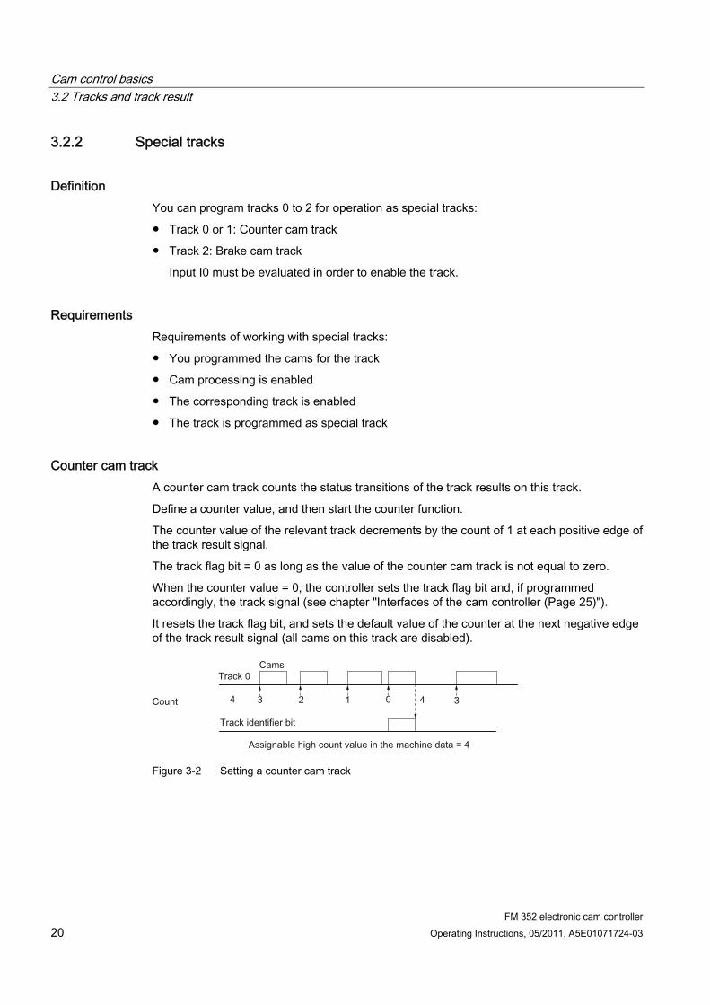
Counter cam track A counter cam track counts the status transitions of the track results on this track.
Define a counter value, and then start the counter function.
The counter value of the relevant track decrements by the count of 1 at each positive edge of the track result signal.
The track flag bit = 0 as long as the value of the counter cam track is not equal to zero.
When the counter value = 0, the controller sets the track flag bit and, if programmed accordingly, the track signal (see chapter "Interfaces of the cam controller (Page 25)").
It resets the track flag bit, and sets the default value of the counter at the next negative edge of the track result signal (all cams on this track are disabled).
Figure 3-2 Setting a counter cam track
Cam control basics 3.2 Tracks and track result
FM 352 electronic cam controller Operating Instructions, 05/2011, A5E01071724-03 21
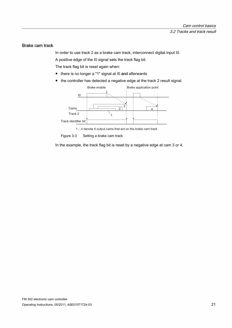
Brake cam track In order to use track 2 as a brake cam track, interconnect digital input I0.
A positive edge of the I0 signal sets the track flag bit.
The track flag bit is reset again when:
● there is no longer a "1" signal at I0 and afterwards
● the controller has detected a negative edge at the track 2 result signal.
Figure 3-3 Setting a brake cam track
In the example, the track flag bit is reset by a negative edge at cam 3 or 4.
Cam control basics 3.3 Hysteresis
FM 352 electronic cam controller 22 Operating Instructions, 05/2011, A5E01071724-03
3.3 Hysteresis
Definition Mechanical imbalance at the axis may cause fluctuation of the actual position value. If the actual position value is offset by one edge of a cam, or within an active cam with only one effective direction, this cam's activation would be cycled on and off continuously. A hysteresis prevents this flutter.
A hysteresis setting is dependent on the actual value, and applies globally to all cams. It is enabled when a direction reversal is detected. A hysteresis will always take effect, regardless of whether or not a cam is set at the current axis position.
Rules for the hysteresis range Rules applicable to the hysteresis range:
● The hysteresis will always be set when a directional reversal is detected.
● The indication of the actual value remains constant within the hysteresis.
● The direction is not redefined within the hysteresis.
● A position-based cam is neither activated nor deactivated within the hysteresis.
● A time-based cam is not activated within the hysteresis. An active time-based cam is deactivated on expiration of the assigned activation (not only on reaching the hysteresis limit).
● When the value is out of the hysteresis range, the FM 352 sets:
– the actual position value
– the current direction of motion of the axis
– the current states of all cams
● The hysteresis range applies to all cams.
Cam control basics 3.3 Hysteresis
FM 352 electronic cam controller Operating Instructions, 05/2011, A5E01071724-03 23
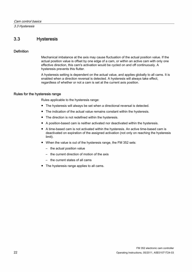
Directional reversal of a cam with hysteresis The table illustrates the reaction to directional reversal. A distinction must be made between the reaction of position- and time-based cams. The effective direction of the cam is positive.
Table 3- 2 Directional reversal of a cam
Position-based cam Time-based cam
The hysteresis will be set when a directional reversal is detected. The cam is deactivated immediately when the hysteresis range is violated.
The cam always remains active for the duration of the assigned activation time.
Cam Hysteresis
Cam control basics 3.4 Dynamic adjustment
FM 352 electronic cam controller 24 Operating Instructions, 05/2011, A5E01071724-03
3.4 Dynamic adjustment
Task The dynamic adjustment is used to compensate delay times of the connected control elements.
Derivative-action time You can program a delay time and assign it as derivative-action time to each cam. You can assign one derivative-action time to each cam. The derivative-action time applies to the cam start and end position.
Actuation distance The actuation distance of a cam is calculated continuously based on the current velocity and derivative-action time. The entire cam is shifted in direction of the actual value by this value. The programmed range is the "static range," and the range calculated based on the derivative-action time represents the "dynamic range."
Actuation distance = <derivative-action time> x <actual velocity of the axis>
FM 352 calculates the actuation distance of all cams within 1/4 of the longest programmed derivative-action time.
An extremely high derivative-action time of a cam reduces the dynamic performance of cam processing.
Cam control basics 3.5 Interfaces of the cam controller
FM 352 electronic cam controller Operating Instructions, 05/2011, A5E01071724-03 25
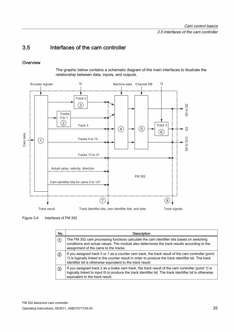
3.5 Interfaces of the cam controller
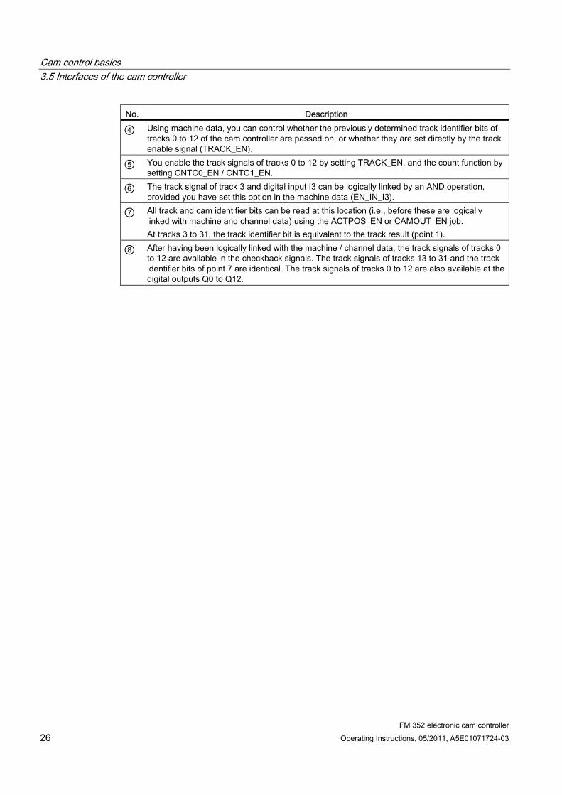
Overview The graphic below contains a schematic diagram of the main interfaces to illustrate the relationship between data, inputs, and outputs.
4 6
1
2
3
5
7 8
Figure 3-4 Interfaces of FM 352
No. Description
① The FM 352 cam processing functions calculate the cam identifier bits based on switching conditions and actual values. The module also determines the track results according to the assignment of the cams to the tracks.
② If you assigned track 0 or 1 as a counter cam track, the track result of the cam controller (point 1) is logically linked to the counter result in order to produce the track identifier bit. The track identifier bit is otherwise equivalent to the track result.
③ If you assigned track 2 as a brake cam track, the track result of the cam controller (point 1) is logically linked to input I0 to produce the track identifier bit. The track identifier bit is otherwise equivalent to the track result.
Cam control basics 3.5 Interfaces of the cam controller
FM 352 electronic cam controller 26 Operating Instructions, 05/2011, A5E01071724-03
No. Description
④ Using machine data, you can control whether the previously determined track identifier bits of tracks 0 to 12 of the cam controller are passed on, or whether they are set directly by the track enable signal (TRACK_EN).
⑤ You enable the track signals of tracks 0 to 12 by setting TRACK_EN, and the count function by setting CNTC0_EN / CNTC1_EN.
⑥ The track signal of track 3 and digital input I3 can be logically linked by an AND operation, provided you have set this option in the machine data (EN_IN_I3).
⑦ All track and cam identifier bits can be read at this location (i.e., before these are logically linked with machine and channel data) using the ACTPOS_EN or CAMOUT_EN job. At tracks 3 to 31, the track identifier bit is equivalent to the track result (point 1).
⑧ After having been logically linked with the machine / channel data, the track signals of tracks 0 to 12 are available in the checkback signals. The track signals of tracks 13 to 31 and the track identifier bits of point 7 are identical. The track signals of tracks 0 to 12 are also available at the digital outputs Q0 to Q12.

FM 352 electronic cam controller Operating Instructions, 05/2011, A5E01071724-03 27
Installing and removing the FM 352 4Important safety rules
Certain important rules and regulations govern the integrating of an S7-300 with FM 894.08 cm a plant or system. These are described in the Operating Instructions SIMATIC S7-300 CPU 31xC and CPU 31x: Installation (http://support.automation.siemens.com/WW/view/en/13008499).
Rail mounting position Horizontal installation of the rail is preferable.
For a vertical installation, make allowances for ambient temperature limits (max. 40 °C).
Selecting slots The FM 352 can be installed in any slot available on the rail for signal modules.
Mechanical configuration Rules for the layout of the modules on a rack:
1. A maximum of 8 FMs are permitted per tier.
2. The maximum number of modules is restricted by the length of the rail and by the mounting width of the modules.
FM 352 requires a mounting width of 80 mm.
3. The number of installed modules (SM, FM, CP) is limited by the permitted current consumption on the S7-300 backplane bus. The current consumption in line 0 (CPU) must not exceed a total of 1.2 A; the value in the expansion lines 1 to 3 must not exceed 0.8 A each. The current consumption of the FM 352 from the backplane bus can be found in the Technical data (Page 166) in the appendix.
Installation and removal tools You require a 4.5 mm screwdriver to install or remove the FM 352.

Installing and removing the FM 352
FM 352 electronic cam controller 28 Operating Instructions, 05/2011, A5E01071724-03
Installing the FM 352 electronic cam controller 1. The FM 352 is supplied with a bus connector. Plug this connector into the bus connector
of module to the left of the FM 352. The bus connector is installed on the rear panel of the module; you may first have to loosen the module again.
2. If you install any further modules on the right side, start by plugging the bus connector of the next module into the right hand bus connector of FM 352.
If the FM 352 is the last module in the tier, do not install a bus connector.
3. Screw-tighten the FM 352 (tightening torque approx. 0.8 N/m to 1.1 N/m).
4. After installation, you can assign a slot number to FM 352. For this purpose, the CPU comes with slot plates.
The required numbering scheme and the procedure for inserting the slot plates can be found in the Operating Instructions SIMATIC S7-300 CPU 31xC and CPU 31x: Installation (http://support.automation.siemens.com/WW/view/en/13008499).
5. Install the shield connection element.
Order No.: 6ES7 390-5AA00-0AA0
Removing the electronic cam controller 1. Switch off the power drive.
2. Switch off the 24 V supply to FM 352.
3. Set the CPU to STOP.
4. Open the front panel covers.
Remove the labeling strip.
5. Unlock and remove the front connector.
6. Remove the sub D connector of the encoder.
7. Loosen the fixing screw on the module.
8. Swivel the module up, and then remove it from the rail.
FM 352 electronic cam controller Operating Instructions, 05/2011, A5E01071724-03 29
Wiring the FM 352 55.1 Before you start wiring
Important safety rule It is imperative for system safety to install the switchgear listed below, and to adapt these to system conditions.
● EMERGENCY STOP switch to shut off the entire system.
● EMERGENCY STOP limit switches directly affecting the power components of all drives.
● Motor circuit-breakers.
Wiring the FM 352 5.2 Description of the encoder interface
FM 352 electronic cam controller 30 Operating Instructions, 05/2011, A5E01071724-03
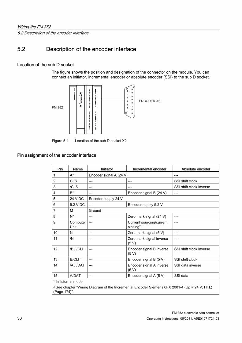
5.2 Description of the encoder interface
Location of the sub D socket The figure shows the position and designation of the connector on the module. You can connect an initiator, incremental encoder or absolute encoder (SSI) to the sub D socket.
Figure 5-1 Location of the sub D socket X2
Pin assignment of the encoder interface
Pin Name Initiator Incremental encoder Absolute encoder 1 A* Encoder signal A (24 V) --- 2 CLS --- --- SSI shift clock 3 /CLS --- --- SSI shift clock inverse 4 B* --- Encoder signal B (24 V) --- 5 24 V DC Encoder supply 24 V 6 5.2 V DC --- Encoder supply 5.2 V 7 M Ground 8 N* --- Zero mark signal (24 V) --- 9 Computer
Unit --- Current sourcing/current
sinking2 ---
10 N --- Zero mark signal (5 V) --- 11 /N --- Zero mark signal inverse
(5 V) ---
12 /B / /CLI 1 --- Encoder signal B inverse (5 V)
SSI shift clock inverse
13 B/CLI 1 --- Encoder signal B (5 V) SSI shift clock 14 /A / /DAT --- Encoder signal A inverse
(5 V) SSI data inverse
15 A/DAT --- Encoder signal A (5 V) SSI data 1 In listen-in mode 2 See chapter "Wiring Diagram of the Incremental Encoder Siemens 6FX 2001-4 (Up = 24 V; HTL) (Page 174)".
Wiring the FM 352 5.3 Connecting the encoder
FM 352 electronic cam controller Operating Instructions, 05/2011, A5E01071724-03 31
5.3 Connecting the encoder
Shield connection element The shield connection element is a comfortable means of bonding all shielded cables to ground, due to the direct connection between the shield connection element and the rack.
You will find detailed information in the Operating Instructions SIMATIC S7-300 CPU 31xC and CPU 31x: Installation (http://support.automation.siemens.com/WW/view/en/13008499).
Procedure 1. Wire the cable to the encoder.
The cables of absolute value encoders may have to be prepared (cable end to encoder) according to the manufacturer specifications.
2. Open the front panel cover and insert the d-sub connector into the FM 352.
3. Secure the connector by tightening the finger screws. Close the front cover.
4. Strip the cable, then clamp the shielding into the shield connection element. Use shield connection terminals.
Wiring the FM 352 5.4 Terminal assignment of the front connector
FM 352 electronic cam controller 32 Operating Instructions, 05/2011, A5E01071724-03
5.4 Terminal assignment of the front connector
Front connector You connect the power supply and the switching elements by wiring these to the front connector.
Terminal assignment of the front connector Terminal Name Meaning 1 L+ 24 V DC encoder supply, and digital outputs 2 M Ground of the encoder supply and digital outputs 3 I 0 Brake enable 4 I 1 Length measurement/ edge detection/ set actual value on-the-fly 5 I 2 Home position switch 6 I 3 Enable track signal 3 7 Q 0 Digital output 0 8 Q 1 Digital output 1 9 Q 2 Digital output 2 10 Q 3 Digital output 3 11 Q 4 Digital output 4 12 Q 5 Digital output 5 13 Q 6 Digital output 6 14 Q 7 Digital output 7 15 Q 8 Digital output 8 16 Q 9 Digital output 9 17 Q 10 Digital output 10 18 Q 11 Digital output 11 19 Q 12 Digital output 12 20 - - - - - -
Auxiliary voltage for encoders and digital outputs (L+, M) The 24 V DC auxiliary voltage of the encoders and digital outputs is monitored:
● for wire-break of the 24 V feed line
● for power failure
The 24 V DC auxiliary supply is converted internally to 5.2 V DC. This supplies 24 V DC and 5 V DC at the encoder interface (sub D socket X2) to the various types of encoders.
The general technical data and requirements for the DC load power supplies are described in the Operating Instructions SIMATIC S7-300 CPU 31xC and CPU 31x: Installation (http://support.automation.siemens.com/WW/view/en/13008499).

Wiring the FM 352 5.4 Terminal assignment of the front connector
FM 352 electronic cam controller Operating Instructions, 05/2011, A5E01071724-03 33
4 digital inputs (I0 to I3) You can connect bounce-free switches (24 V current sourcing) or non-contact sensors (2- or 3-wire proximity switches) to the 4 digital inputs.
The digital inputs are not monitored for short circuits or wire break and have a non-isolated connection to the module chassis.
13 digital outputs (Q0 to Q12) The state (on/off) of tracks 0 to 12 is output at 13 digital outputs. The digital outputs have a non-isolated connection to the module chassis.
Loads supported:
● Operating voltage 24 V
● Current load 0.5 A / short-circuit proof
The state of each output can be read off from the respective LED.

Wiring the FM 352 5.5 Wiring the front connector
FM 352 electronic cam controller 34 Operating Instructions, 05/2011, A5E01071724-03
5.5 Wiring the front connector
Connecting cables ● The cables for digital IO must be shielded if they exceed a certain lengths:
– Digital inputs: cable length > 32 m
– Digital outputs: cable length > 100 m
● The encoder cables must be shielded.
● The shields of the encoder cables must be terminated at the shielding / ground conductor busbar, and on the IO connectors.
● Always use twisted-pair cables for the A/DAT, /A / /DAT, B/CLI, /B / /CLI, CLS, /CLS and N, and /N signals of the incremental encoder.
● Use flexible connecting cables with a conductor cross-section of 0.25 to 1.5 mm2
● Wire end ferrules are not required. However, should you prefer to use these, you can crimp and wire two wires with a conductor cross-section of 0.25 to 0.75 mm2 using a single ferrule without insulation collar (DIN 46228, design A, short version).
Note
If you connect measuring probes or proximity switches, you must use shielded cables to achieve optimum noise immunity.
Note on wiring 24 V DC
CAUTION The module can be damaged.
If you reverse the polarity of the encoder supply, the module will be destroyed and must be replaced!
Verify the correct polarity of the encoder supply (1L+, 1M)
Tools required 3.5-mm screwdriver or power screwdriver
Wiring the FM 352 5.5 Wiring the front connector
FM 352 electronic cam controller Operating Instructions, 05/2011, A5E01071724-03 35
Procedure
WARNING Personal injury and damage to equipment on account of unshielded voltage.
If you wire the FM 352 front connector while the system is in live state, you will risk injury from electric shock!
Always switch off power before you wire the FM 352!
If no EMERGENCY OFF switch is installed, damage may be caused by connected aggregates.
Install an EMERGENCY OFF switch to be able to shut down the connected drives while operating the FM 352 via the Parameter assignment interface.
To wire the front connector:
1. Strip the wires to length of 6 mm. Crimp on wire end ferrules as required.
2. Open the front panel cover, then position the front connector for wiring.
3. install the cable strain relief in the connector.
4. To exit the cables at the bottom, terminate the wires starting at the bottom, otherwise at the top. Screw-tighten any unused terminals. Tightening torque = 0.6 N/m to 0.8 N/m.
5. Tighten the strain relief for the cable harness.
6. Move the front connector into operating position (press the interlocking element while doing so).
7. You can fill out the included label and insert it into the front panel cover.
Non-isolation The chassis of the encoder supply has a non-isolated connection to the chassis of the CPU; i.e., you have to connect terminal 2 (1M) to the chassis of the CPU or the IM 153 using a low-impedance connection.

Wiring the FM 352 5.5 Wiring the front connector
FM 352 electronic cam controller 36 Operating Instructions, 05/2011, A5E01071724-03
FM 352 electronic cam controller Operating Instructions, 05/2011, A5E01071724-03 37
Installing the software 6Introduction
You assign parameters for the FM 352 using the Parameter assignment interface. This interface is designed for FM 352 and FM 452. A description of the Programming interface is available in the Online Help.
Requirements Before starting to assign parameters for the FM 352 Electronic Cam Controller, note the requirements in the readme.rtf file, in particular, the required version of STEP 7. The readme.rtf file is available on the CD included in your shipment.
Installation To install the configuration package:
1. Place the supplied CD in the CD drive of your programming device / PC.
2. Start the Setup.exe program.
3. Follow the operating instructions provided by the installation program.
Result The components of the configuration package are installed in the following directories:
● SIEMENS\STEP7\S7LIBS\FMx52LIB: FBs, FCs, and UDTs
● SIEMENS\STEP7\S7FCAM: Parameter assignment interface, Readme, Online Help
● SIEMENS\STEP7\EXAMPLES\zEn19_01andzEn19_02: Examples for FM 452 and FM 352
● SIEMENS\STEP7\MANUAL: Getting Started, Manuals
Note
If, when installing STEP 7, you chose a directory other than SIEMENS\STEP7, this directory will be entered.
Configuring and assigning parameters For further information, refer to the chapter "Commissioning the FM 352 (Page 61)".

Installing the software
FM 352 electronic cam controller 38 Operating Instructions, 05/2011, A5E01071724-03
FM 352 electronic cam controller Operating Instructions, 05/2011, A5E01071724-03 39
Programming the FM 352 7
If your CPU supports the system blocks SFB 52 and SFB 53 with DPV1 functionality Then use the blocks from the program folder "FM 352 CAM V2" to program the FM 352.
In addition to centralized use in the S7-300, these blocks also support distributed use with PROFINET and PROFIBUS DP.
You will find a description in this section.
If your CPU does not support the system blocks SFB 52 and SFB 53 with DPV1 functionality Then use the blocks from the program folder "FM 352,452 CAM V1" to program the FM 352.
For a description, please refer to Appendix D "Programming without SFB 52 and SFB 53 (Page 199)".
Programming the FM 352 7.1 Basics of Programming an FM 352
FM 352 electronic cam controller 40 Operating Instructions, 05/2011, A5E01071724-03
7.1 Basics of Programming an FM 352
Task You can assign parameters, control, and commission the FM 352 module via a user program. To exchange data between the user program and module, you use the functions (FCs) and data blocks (DBs) described below.
Preparation ● Open the block library FM352LIB in SIMATIC Manager, then copy the required functions
(FCs), function blocks (FBs), and block templates (UDTs) to the block container of your project. If the block numbers are already being used, assign new numbers. The block names are entered unchanged in the symbol table of your S7 program.
– CAM_INIT (FC 0):
You need this FC to initialize the channel DB following a module startup.
– CAM_CTRL (FB 1):
You need this FB for data exchange with the module. The instance DB for this block is called "channel DB".
– CAM_DIAG (FB 2):
You need this FB when you process detailed diagnostic information in the program or want to make this information available to an operator control and monitoring system. The instance DB for this block is referred to as a "diagnostic DB".
– CAM_P016TYPE (UDT3):
You need this UDT to generate a parameter DB with machine data and data for 16 cams. The parameter DB is used by the FB CAM_CTRL to write or read machine or cam data.
– CAM_P032TYPE (UDT4):
Same as CAM_P016TYPE, however for 32 cams
– CAM_P064TYPE (UDT5):
Same as CAM_P016TYPE, however for 64 cams
– CAM_P128TYPE (UDT6):
Same as CAM_P016TYPE, however for 128 cams
● Create data blocks using the UDTs in the block folder of your S7 program. If you are using multiple modules, you require a separate set of data blocks for each module used.
Programming the FM 352 7.1 Basics of Programming an FM 352
FM 352 electronic cam controller Operating Instructions, 05/2011, A5E01071724-03 41
● Enter the module address in the channel DB and, if necessary, also in the diagnostic DB in the MOD_ADDR parameter.
Proceed as follows to enter the module address:
– Recommended procedure:
Assign the module address to the channel DB/diagnostic DB in the user program so that the assignment of the module address takes place when you call the user program in OB 100.
– Alternative procedure:
You can have the module address entered automatically if you select the module in HW Config, open the "Properties" dialog with the menu command Edit > Object Properties, and use the "Mod_Adr" button there to select a channel DB and diagnostic DB, if necessary. But in this case the values entered in the channel DB/diagnostic DB (including the module address) are reset to their initial values in the event of a consistency check (menu command Edit > Check block consistency opens the "Check block consistency" dialog) followed by a compilation (menu command Program > Compile All in the "Check block consistency" dialog box).
The values are not changed if there is only a consistency check without compilation.
The menu command Edit > Compile All is only required within the consistency check if the project was last edited with STEP 7 V5.0 Service Pack 2 or later.
● If your PG/PC is connected to a CPU, you can now download the blocks to the CPU.
Programming the FM 352 7.2 FC CAM_INIT (FC 0)
FM 352 electronic cam controller 42 Operating Instructions, 05/2011, A5E01071724-03
7.2 FC CAM_INIT (FC 0)
Tasks FC CAM_INIT initializes the following data in the channel DB:
● The control signals
● The checkback signals
● The trigger, done and error bits of the jobs
● The function switches and their done and error bits
● Job management and the internal buffers for FB CAM_CTRL
Call The function must be executed after a startup, i.e., after the power supply to the module or CPU is switched on. You should therefore insert it, for example, in the restart OB (OB100) and the removal/insertion OB (OB83) or call it in the initialization phase of your user program. This ensures that your user program does not access obsolete data after a CPU or module restart.
Call parameters
Name Data type P-type Meaning DB_NO INT I Number of the channel DB
Return values This function does not return a return value.
Programming the FM 352 7.3 FB CAM_CTRL (FB 1)
FM 352 electronic cam controller Operating Instructions, 05/2011, A5E01071724-03 43
7.3 FB CAM_CTRL (FB 1)
Tasks You can use FB CAM_CTRL to read operating data from the module, initialize the module, and control it during operation. For these tasks, you use the control signals, checkback signals, and write and read jobs.
Each time it is called, the function block performs the following actions:
● Read checkback signals:
The FB CAM_CTRL reads all checkback signals from the module and enters these in the channel DB. The control signals and jobs are not executed until this task is completed, and thus the checkback signals reflect the module status prior to the block call.
● Write control signals:
The control signals written to the channel DB are transferred to the module. Enabling of cam processing, however, is delayed as long as the trigger for a "Set reference point" job or "Write cam data" job is set. The activation (or reactivation) of cam processing is delayed by this time.
● Execute job:
The next job is executed based on the trigger bits for jobs entered in the channel DB.
Call The function block must be called cyclically.
Before you call the block, enter all the data in the channel DB that are required to execute the intended functions.
Data used ● Channel DB:
The module address must be entered in the channel DB.
● Parameter DB:
If you want to write or read machine or cam data using jobs, you require a parameter DB whose number must be entered in the channel DB. The size of the parameter DB must be adequate for the number of cams.
Parameters Parameter Declaration Data type Description DB_NO INPUT INT Number of the channel DB RETVAL OUTPUT INT Return value
Programming the FM 352 7.3 FB CAM_CTRL (FB 1)
FM 352 electronic cam controller 44 Operating Instructions, 05/2011, A5E01071724-03
Jobs Data exchange with the module other than the control and checkback signals is handled using jobs.
To start a job, set the corresponding trigger bit in the channel DB and provide the relevant data for write jobs. You then call FB CAM_CTRL to execute the job.
If you use the FM 352 centrally, a read job is executed immediately. If you use the FM 352 in a distributed system, a read job may take several cycles.
Due to the required confirmations from the module, a write job requires at least 3 calls (or OB cycles). If you use the FM 352 in a distributed system, a write job may take more than 3 calls.
You can send several jobs at the same time, if necessary, along with control signals. With the exception of the job for writing the function switches, the jobs are executed in the order of the trigger bits specified in the channel DB. Once a job has been completed, the trigger bit is canceled. The next time the block is called, the subsequent job is identified and executed.
For each job there is not only a trigger bit but also a done bit and an error bit. In their names, instead of the ending _EN for "enable", they have the ending _D for "done" or _ERR for "error". Done and error bits of the job should be set to 0 after they have been evaluated or before the job is started.
If you set the JOBRESET bit, all the done and error bits are reset before the pending jobs are processed. The JOBRESET bit is then reset to 0.
Function switches The function switches activate and deactivate module states. A job for writing the function switches is only executed when there is a change in a switch setting. The setting of the function switch is latched after the job has been executed.
Length measurements and edge detection must not be activated at the same time. For this reason, FB CAM_CTRL makes sure that when one of the function switches is activated, the other is deactivated. If you do activate both function switches at the same time (0 → 1), the length measurement is activated.
Function switches and jobs can be used at the same time in one FB CAM_CTRL call.
As with the jobs, there are done bits with the ending _D and error bits with the ending _ERR for the function switches.
To be able to evaluate the done and error bits, you should set these bits to 0 when you change a function switch.
Programming the FM 352 7.3 FB CAM_CTRL (FB 1)
FM 352 electronic cam controller Operating Instructions, 05/2011, A5E01071724-03 45
Startup Call FC CAM_INIT at the startup of the module or CPU (see chapter "FC CAM_INIT (FC 0) (Page 42)"). Among other things, this resets the function switches.
FB CAM_CTRL acknowledges the module startup. During this time, RETVAL and JOBBUSY = 1.
Return values The block returns the following return values in the RETVAL parameter of the channel DB in word 372:
RETVAL BR Description
1 1 At least 1 job active 0 1 No job active, no error -1 0 Error:
Data error (DAT_ERR) or Communication error (JOB_ERR) occurred
Job status You can read the status of the job execution using the RETVAL return value and the JOBBUSY activity bit in the channel DB. You can determine the status of a single job by evaluating its trigger, done, and error bits.
RETVAL JOBBUSY Trigger bit _EN Done bit _D Error bit _ERR Job active 1 1 1 0 0 Job completed without errors
0 0 0 1 0
Job completed with errors
-1 0 0 1 1
Write job aborted -1 0 0 0 1

Programming the FM 352 7.3 FB CAM_CTRL (FB 1)
FM 352 electronic cam controller 46 Operating Instructions, 05/2011, A5E01071724-03
Reaction to errors If faulty data were written by a write job, the module returns the message DATA_ERR = 1. If an error occurs during communication with the module for a write or read job, the cause of the error is entered in the JOB_ERR parameter in the channel DB.
● Error in a write job:
If an error occurs in a job, the trigger bit is canceled and error bit _ERR and done bit _D are set. The trigger bit is canceled and error bit _ERR is also set for all write jobs still pending.
The pending read jobs will continue to be processed. JOB_ERR is reset again for each job.
● Error in a read job:
If an error occurs in a job, the trigger bit is canceled and error bit _ERR and done bit _D are set.
The read jobs still pending continue to be processed. JOB_ERR is reset again for each job.
For further error information, refer to the JOB_ERR and DATA_ERR parameters (see chapter "Diagnostics (Page 145)" and "Data and Structure of the Diagnostic DB (Page 187)").
Application in the user program The FB CAM_CTRL is indeed a multiple instance block, however cannot be used as a multiple instance in a user block.
Programming the FM 352 7.4 FB CAM_DIAG (FB 2)
FM 352 electronic cam controller Operating Instructions, 05/2011, A5E01071724-03 47
7.4 FB CAM_DIAG (FB 2)
Tasks Use FB CAM_DIAG to read the diagnostic buffer of the module and make it available for display on an operator control and monitoring system or for a programmed evaluation.
Call The function block must be called cyclically. It is not permitted to initiate a second call in an interrupt OB. At least two calls (cycles) are required to completely execute this function.
The function block reads the diagnostic buffer when a new entry in the diagnostic buffer is indicated by checkback signal DIAG = 1. After the diagnostic buffer is read, DIAG is set to 0 by the module.
Data used ● Diagnostic DB:
The module address must be entered in the diagnostic DB. The newest entry in the diagnostics buffer is written in the DIAG[1] structure and the oldest entry is written in the DIAG[4] structure.
Jobs You can read the diagnostic buffer whether or not there is a new entry by setting the DIAGRD_EN trigger bit. After reading the diagnostic buffer, the trigger bit is set to 0.
Parameters Parameter Declaration Data type Description DB_NO INPUT INT Number of the diagnostic DB RETVAL OUTPUT INT Return value
Startup There is no startup processing associated with the function block.
Programming the FM 352 7.4 FB CAM_DIAG (FB 2)
FM 352 electronic cam controller 48 Operating Instructions, 05/2011, A5E01071724-03
Return values The block returns the following return values in the RETVAL parameter of the diagnostic DB in word 302:
RETVAL BR Description
1 1 Job active 0 1 No job active, no error -1 0 Error
Reaction to errors The cause of a job error can be found in the JOB_ERR parameter of the diagnostic DB (see chapter "Diagnostics (Page 145)" and "Data and Structure of the Diagnostic DB (Page 187)").
Application in the user program The FB CAM_DIAG is indeed a multiple instance block, however cannot be used as a multiple instance in a user block.
Programming the FM 352 7.5 Data blocks
FM 352 electronic cam controller Operating Instructions, 05/2011, A5E01071724-03 49
7.5 Data blocks
7.5.1 Templates for data blocks The included FM352LIB library contains a block template (UDT) for the different variants of the machine data DB. Based on this UDT, you can create data blocks with user-specific numbers and names. You generate channel and diagnostic DBs as instances of FB 1 and FB 2.
7.5.2 Channel DB
Task The channel DB forms the data interface between the user program and the FM 352 electronic cam controller. It contains and accepts all data required for controlling and operating the module.
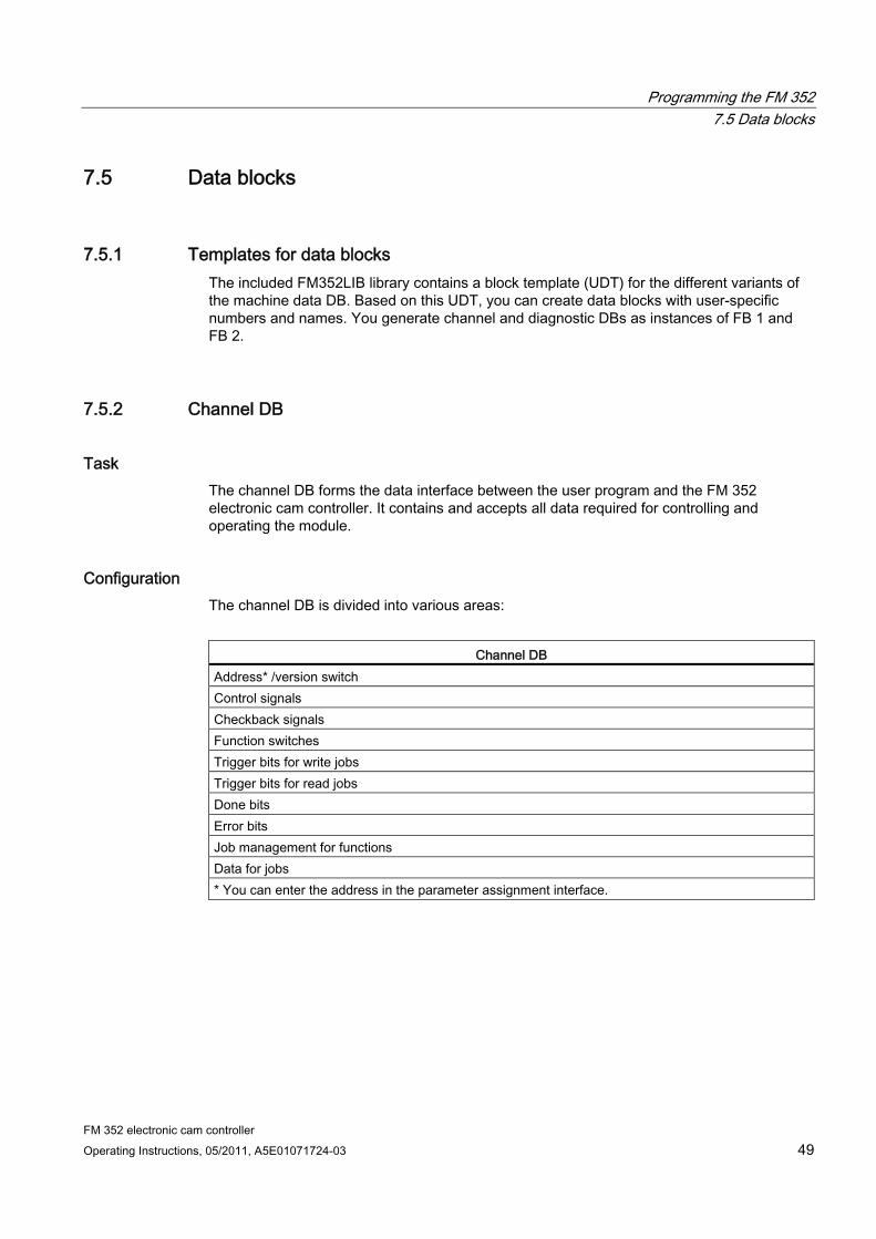
Configuration The channel DB is divided into various areas:
Channel DB
Address* /version switch Control signals Checkback signals Function switches Trigger bits for write jobs Trigger bits for read jobs Done bits Error bits Job management for functions Data for jobs * You can enter the address in the parameter assignment interface.
Programming the FM 352 7.5 Data blocks
FM 352 electronic cam controller 50 Operating Instructions, 05/2011, A5E01071724-03
7.5.3 Diagnostic DB
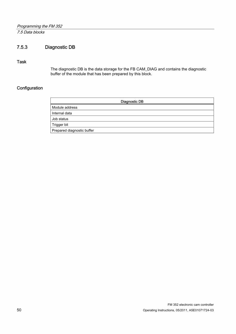
Task The diagnostic DB is the data storage for the FB CAM_DIAG and contains the diagnostic buffer of the module that has been prepared by this block.
Configuration
Diagnostic DB Module address Internal data Job status Trigger bit Prepared diagnostic buffer
Programming the FM 352 7.5 Data blocks
FM 352 electronic cam controller Operating Instructions, 05/2011, A5E01071724-03 51
7.5.4 Parameter DB
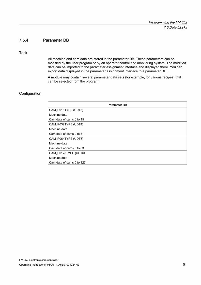
Task All machine and cam data are stored in the parameter DB. These parameters can be modified by the user program or by an operator control and monitoring system. The modified data can be imported to the parameter assignment interface and displayed there. You can export data displayed in the parameter assignment interface to a parameter DB.
A module may contain several parameter data sets (for example, for various recipes) that can be selected from the program.
Configuration
Parameter DB CAM_P016TYPE (UDT3) Machine data Cam data of cams 0 to 15 CAM_P032TYPE (UDT4) Machine data Cam data of cams 0 to 31 CAM_P064TYPE (UDT5) Machine data Cam data of cams 0 to 63 CAM_P0128TYPE (UDT6) Machine data Cam data of cams 0 to 127
Programming the FM 352 7.6 Interrupts
FM 352 electronic cam controller 52 Operating Instructions, 05/2011, A5E01071724-03
7.6 Interrupts
Interrupt processing The FM 352 can trigger hardware and diagnostic interrupts. You process those interrupts in an interrupt OB. If an interrupt is triggered and the corresponding OB is not loaded, the CPU goes to STOP mode (refer to the Programming with STEP 7 Manual).
You can enable interrupt processing in the following stages:
1. Global interrupt enable for the entire module
– Select the module in HW Config
Select Edit > Object Properties > Basic Parameters, then enable the diagnostic and/or hardware interrupt.
– Select the OB number for the hardware interrupt using Edit > Object Properties > Addresses.
– Save and compile the hardware configuration.
– Download the hardware configuration to the CPU.
2. Enable the hardware interrupt events in the machine data.
3. Assign the hardware interrupts in the cam data for cams 0 to 7.
Programming the FM 352 7.7 Evaluation of a hardware interrupt
FM 352 electronic cam controller Operating Instructions, 05/2011, A5E01071724-03 53
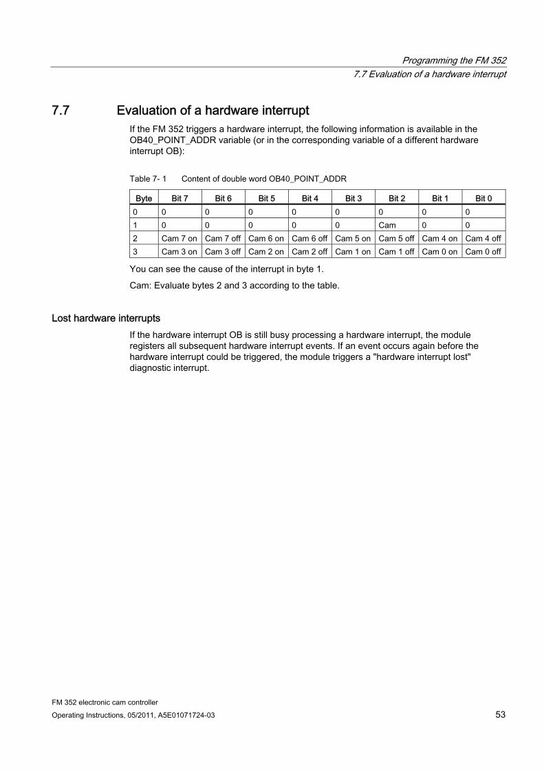
7.7 Evaluation of a hardware interrupt If the FM 352 triggers a hardware interrupt, the following information is available in the OB40_POINT_ADDR variable (or in the corresponding variable of a different hardware interrupt OB):
Table 7- 1 Content of double word OB40_POINT_ADDR
Byte Bit 7 Bit 6 Bit 5 Bit 4 Bit 3 Bit 2 Bit 1 Bit 0 0 0 0 0 0 0 0 0 0 1 0 0 0 0 0 Cam 0 0 2 Cam 7 on Cam 7 off Cam 6 on Cam 6 off Cam 5 on Cam 5 off Cam 4 on Cam 4 off3 Cam 3 on Cam 3 off Cam 2 on Cam 2 off Cam 1 on Cam 1 off Cam 0 on Cam 0 off
You can see the cause of the interrupt in byte 1.
Cam: Evaluate bytes 2 and 3 according to the table.
Lost hardware interrupts If the hardware interrupt OB is still busy processing a hardware interrupt, the module registers all subsequent hardware interrupt events. If an event occurs again before the hardware interrupt could be triggered, the module triggers a "hardware interrupt lost" diagnostic interrupt.
Programming the FM 352 7.8 Evaluating a diagnostics interrupt
FM 352 electronic cam controller 54 Operating Instructions, 05/2011, A5E01071724-03
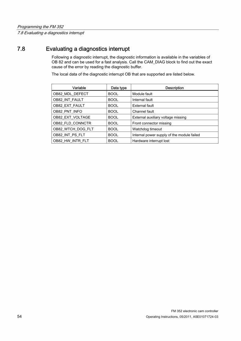
7.8 Evaluating a diagnostics interrupt Following a diagnostic interrupt, the diagnostic information is available in the variables of OB 82 and can be used for a fast analysis. Call the CAM_DIAG block to find out the exact cause of the error by reading the diagnostic buffer.
The local data of the diagnostic interrupt OB that are supported are listed below.
Variable Data type Description
OB82_MDL_DEFECT BOOL Module fault OB82_INT_FAULT BOOL Internal fault OB82_EXT_FAULT BOOL External fault OB82_PNT_INFO BOOL Channel fault OB82_EXT_VOLTAGE BOOL External auxiliary voltage missing OB82_FLD_CONNCTR BOOL Front connector missing OB82_WTCH_DOG_FLT BOOL Watchdog timeout OB82_INT_PS_FLT BOOL Internal power supply of the module failed OB82_HW_INTR_FLT BOOL Hardware interrupt lost
Programming the FM 352 7.9 Technical data
FM 352 electronic cam controller Operating Instructions, 05/2011, A5E01071724-03 55
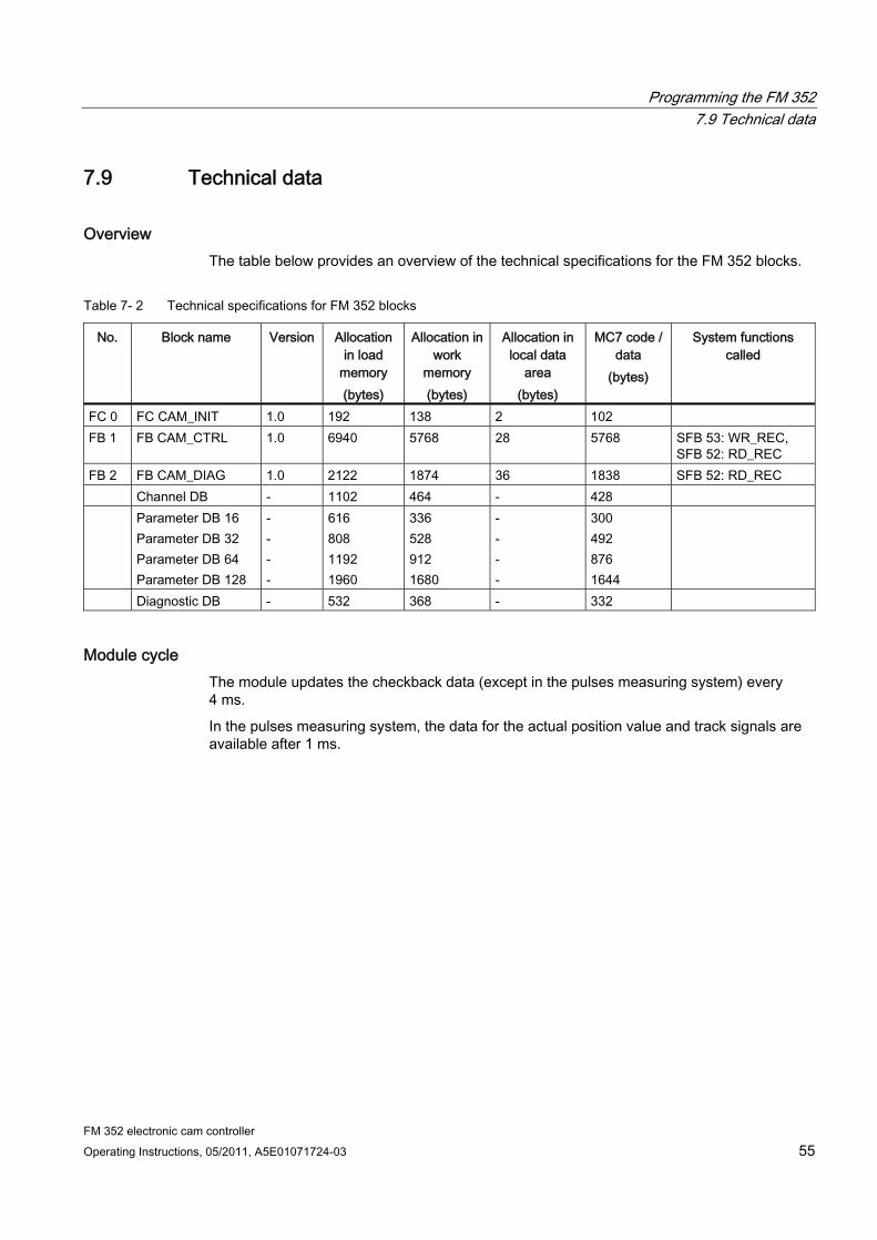
7.9 Technical data
Overview The table below provides an overview of the technical specifications for the FM 352 blocks.
Table 7- 2 Technical specifications for FM 352 blocks
No. Block name Version Allocation in load
memory (bytes)
Allocation in work
memory (bytes)
Allocation in local data
area (bytes)
MC7 code / data
(bytes)
System functions called
FC 0 FC CAM_INIT 1.0 192 138 2 102 FB 1 FB CAM_CTRL 1.0 6940 5768 28 5768 SFB 53: WR_REC,
SFB 52: RD_REC FB 2 FB CAM_DIAG 1.0 2122 1874 36 1838 SFB 52: RD_REC Channel DB - 1102 464 - 428 Parameter DB 16
Parameter DB 32 Parameter DB 64 Parameter DB 128
- - - -
616 808 1192 1960
336 528 912 1680
- - - -
300 492 876 1644
Diagnostic DB - 532 368 - 332
Module cycle The module updates the checkback data (except in the pulses measuring system) every 4 ms.
In the pulses measuring system, the data for the actual position value and track signals are available after 1 ms.
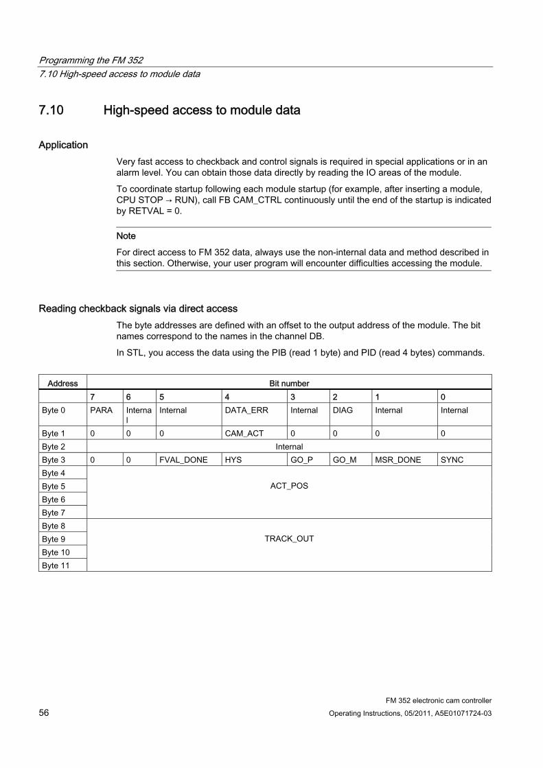
Programming the FM 352 7.10 High-speed access to module data
FM 352 electronic cam controller 56 Operating Instructions, 05/2011, A5E01071724-03
7.10 High-speed access to module data
Application Very fast access to checkback and control signals is required in special applications or in an alarm level. You can obtain those data directly by reading the IO areas of the module.
To coordinate startup following each module startup (for example, after inserting a module, CPU STOP → RUN), call FB CAM_CTRL continuously until the end of the startup is indicated by RETVAL = 0.
Note
For direct access to FM 352 data, always use the non-internal data and method described in this section. Otherwise, your user program will encounter difficulties accessing the module.
Reading checkback signals via direct access The byte addresses are defined with an offset to the output address of the module. The bit names correspond to the names in the channel DB.
In STL, you access the data using the PIB (read 1 byte) and PID (read 4 bytes) commands.
Address Bit number
7 6 5 4 3 2 1 0 Byte 0 PARA Interna
l Internal DATA_ERR Internal DIAG Internal Internal
Byte 1 0 0 0 CAM_ACT 0 0 0 0 Byte 2 Internal Byte 3 0 0 FVAL_DONE HYS GO_P GO_M MSR_DONE SYNC Byte 4 Byte 5 Byte 6 Byte 7
ACT_POS
Byte 8 Byte 9 Byte 10 Byte 11
TRACK_OUT
Programming the FM 352 7.10 High-speed access to module data
FM 352 electronic cam controller Operating Instructions, 05/2011, A5E01071724-03 57
Direct write access to control signals The byte addresses are defined with an offset to the input address of the module. The bit names correspond to the names in the channel DB.
In STL, you access the data using the PQB (write 1 byte) and PQW (write 2 bytes) commands.
Address Bit number
7 6 5 4 3 2 1 0 Byte 0 Internal Byte 1 0 CNTC1_EN CNTC0_EN CAM_EN DIR_P DIR_M 0 0 Byte 2 Byte 3
TRACK_EN
Example: Actual position value (ACT_POS) The start address of the module is 512.
STL
L PID 516 Read the current actual position value (ACT_POS) with direct access: Module start address + 4
Programming the FM 352 7.11 Parameter transmission paths
FM 352 electronic cam controller 58 Operating Instructions, 05/2011, A5E01071724-03
7.11 Parameter transmission paths
Transmission paths The term parameter refers to the following machine and cam data.
Figure 7-1 Parameter transmission paths
1 Save the parameters in the parameter assignment interface. 2 Saving and compiling the HW configuration, and download to the CPU. 3 The CPU writes the parameters to the module during system parameter assignment. 4 Upload the module parameters to the PG by selecting the "PLC > Upload to PG" command. 5 Download the parameters from the parameter assignment interface to the module with the
"PLC > Download" command. 6 Write parameters to the module using jobs in the user program. 7 Read parameters from the module using jobs in the user program. 8 Save parameters from the user program to the online DB. 9 Read in parameters from the online DB to the user program. 10 Export parameters from the parameter assignment interface to the DB (offline or online DB);
an offline DB must then be downloaded to the CPU. 11 Import parameters from an online or offline DB into the parameter assignment interface.
Programming the FM 352 7.11 Parameter transmission paths
FM 352 electronic cam controller Operating Instructions, 05/2011, A5E01071724-03 59
Some use cases for the transfer of parameters Use case Steps You edit the parameters on the parameter assignment interface. The parameter should then be assigned automatically to the module during startup.
Perform steps 1, 2, and 3.
You edit parameters on the parameter assignment interface in the commissioning test mode:
Perform steps 4 and 5
The parameters edited during commissioning should be downloaded automatically during startup.
Perform steps 1, 2, and 3.
Create the parameters using the parameter assignment interface. When it starts up, the module should be assigned parameters only by the user program using data blocks.
Perform steps 10 and 6.
You need a comfortable means of creating data records for recipes. Perform step 10. Create the parameters using the parameter assignment interface. These should be available to the user program for temporary modifications.
Perform steps 1, 2, and 3 for automatic parameter assignment. Perform steps 10, 7 to enable access by the user program.
You modify existing parameters (exclusively) using the user program.
Perform steps 7, 9, 8, and 6.
You want to view the data modified by the user program on the parameter assignment interface.
Perform step 11.
Parameters modified by the user program should also be loaded automatically during startup.
Perform steps 6, 11, 1, 2, and 3.

Programming the FM 352 7.11 Parameter transmission paths
FM 352 electronic cam controller 60 Operating Instructions, 05/2011, A5E01071724-03
FM 352 electronic cam controller Operating Instructions, 05/2011, A5E01071724-03 61
Commissioning the FM 352 8Important notes
Please observe the points listed in the following warnings.
WARNING In order to prevent injury and material damage:
Install an EMERGENCY STOP switch in the area of the computer. This is the only way to ensure that the system can be switched off safely in the event of a computer or software failure.
Install an EMERGENCY STOP limit switch which directly affects the power units of all drives.
Always make sure to prevent access to the plant areas containing moving parts.
Concurrent controlling and monitoring of the FM 352 from your user program and on the Test > Commissioning screen form can lead to conflicts with unforeseeable effects. Hence, always set the CPU to STOP when working in the Test screen form, or disable the user program.
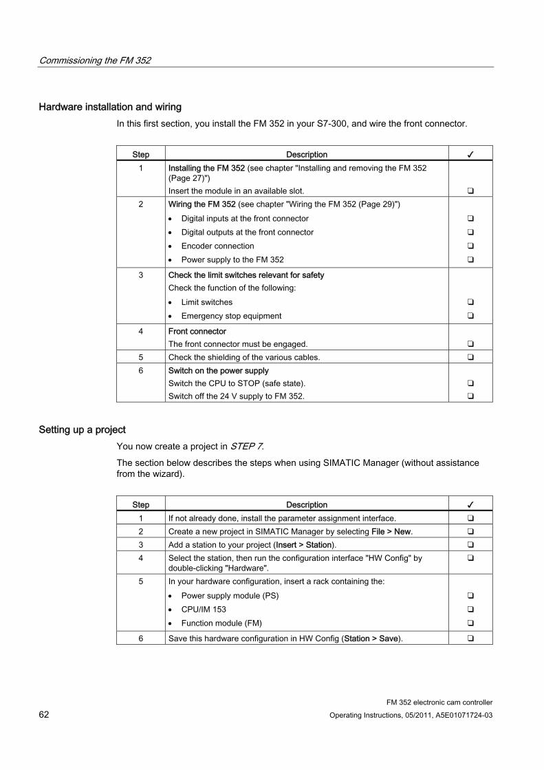
Commissioning the FM 352
FM 352 electronic cam controller 62 Operating Instructions, 05/2011, A5E01071724-03
Hardware installation and wiring In this first section, you install the FM 352 in your S7-300, and wire the front connector.
Step Description ✓
1 Installing the FM 352 (see chapter "Installing and removing the FM 352 (Page 27)") Insert the module in an available slot.
❑ 2 Wiring the FM 352 (see chapter "Wiring the FM 352 (Page 29)")
Digital inputs at the front connector Digital outputs at the front connector Encoder connection Power supply to the FM 352
❑ ❑ ❑ ❑
3 Check the limit switches relevant for safety Check the function of the following: Limit switches Emergency stop equipment
❑ ❑
4 Front connector The front connector must be engaged.
❑
5 Check the shielding of the various cables. ❑ 6 Switch on the power supply
Switch the CPU to STOP (safe state). Switch off the 24 V supply to FM 352.
❑ ❑
Setting up a project You now create a project in STEP 7.
The section below describes the steps when using SIMATIC Manager (without assistance from the wizard).
Step Description ✓
1 If not already done, install the parameter assignment interface. ❑ 2 Create a new project in SIMATIC Manager by selecting File > New. ❑ 3 Add a station to your project (Insert > Station). ❑ 4 Select the station, then run the configuration interface "HW Config" by
double-clicking "Hardware". ❑
5 In your hardware configuration, insert a rack containing the: Power supply module (PS) CPU/IM 153 Function module (FM)
❑ ❑ ❑
6 Save this hardware configuration in HW Config (Station > Save). ❑
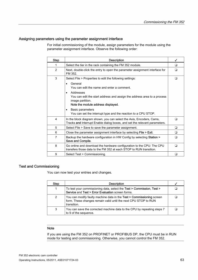
Commissioning the FM 352
FM 352 electronic cam controller Operating Instructions, 05/2011, A5E01071724-03 63
Assigning parameters using the parameter assignment interface For initial commissioning of the module, assign parameters for the module using the parameter assignment interface. Observe the following order:
Step Description ✓
1 Select the tier in the rack containing the FM 352 module. ❑ 2 Next, double-click the entry to open the parameter assignment interface for
FM 352. ❑
3 Select File > Properties to edit the following settings: General
You can edit the name and enter a comment. Addresses
You can edit the start address and assign the address area to a process image partition. Note the module address displayed.
Basic parameters You can set the interrupt type and the reaction to a CPU STOP.
❑
4 In the block diagram shown, you can select the Axis, Encoders, Cams, Tracks and Interrupt Enable dialog boxes, and set the relevant parameters.
❑
5 Select File > Save to save the parameter assignment. ❑ 6 Close the parameter assignment interface by selecting File > Exit. ❑ 7 Backup the hardware configuration in HW Config by selecting Station >
Save and Compile. ❑
8 Go online and download the hardware configuration to the CPU: The CPU transfers those data to the FM 352 at each STOP to RUN transition.
❑
9 Select Test > Commissioning. ❑
Test and Commissioning You can now test your entries and changes.
Step Description ✓
1 To test your commissioning data, select the Test > Commission, Test > Service and Test > Error Evaluation screen forms.
❑
2 You can modify faulty machine data in the Test > Commissioning screen form. These changes remain valid until the next CPU STOP to RUN transition.
❑
3 You can save the corrected machine data to the CPU by repeating steps 7 to 9 of the sequence.
❑
Note
If you are using the FM 352 on PROFINET or PROFIBUS DP, the CPU must be in RUN mode for testing and commissioning. Otherwise, you cannot control the FM 352.
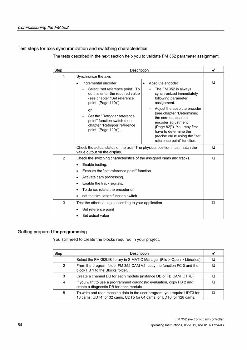
Commissioning the FM 352
FM 352 electronic cam controller 64 Operating Instructions, 05/2011, A5E01071724-03
Test steps for axis synchronization and switching characteristics The tests described in the next section help you to validate FM 352 parameter assignment.
Step Description ✔
Synchronize the axis
Incremental encoder – Select "set reference point". To
do this enter the required value (see chapter "Set reference point (Page 110)").
or – Set the "Retrigger reference
point" function switch (see chapter "Retrigger reference point (Page 120)").
Absolute encoder – The FM 352 is always
synchronized immediately following parameter assignment.
– Adjust the absolute encoder (see chapter "Determining the correct absolute encoder adjustment (Page 82)"). You may first have to determine the precise value using the "set reference point" function.
❑ 1
Check the actual status of the axis. The physical position must match the value output on the display.
❑
2 Check the switching characteristics of the assigned cams and tracks. Enable testing. Execute the "set reference point" function. Activate cam processing. Enable the track signals. To do so, rotate the encoder or set the simulation function switch.
❑
3 Test the other settings according to your application Set reference point Set actual value
❑
Getting prepared for programming You still need to create the blocks required in your project.
Step Description ✔
1 Select the FMX52LIB library in SIMATIC Manager (File > Open > Libraries). ❑ 2 From the program folder FM 352 CAM V2, copy the function FC 0 and the
block FB 1 to the Blocks folder. ❑
3 Create a channel DB for each module (instance DB of FB CAM_CTRL). ❑ 4 If you want to use a programmed diagnostic evaluation, copy FB 2 and
create a diagnostic DB for each module. ❑
5 To write and read machine data in the user program, you require UDT3 for 16 cams, UDT4 for 32 cams, UDT5 for 64 cams, or UDT6 for 128 cams.
❑
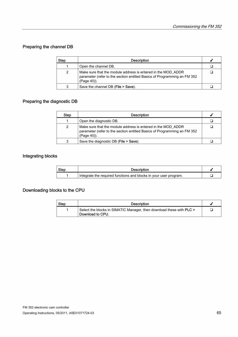
Commissioning the FM 352
FM 352 electronic cam controller Operating Instructions, 05/2011, A5E01071724-03 65
Preparing the channel DB Step Description ✔
1 Open the channel DB. ❑ 2 Make sure that the module address is entered in the MOD_ADDR
parameter (refer to the section entitled Basics of Programming an FM 352 (Page 40)).
❑
3 Save the channel DB (File > Save). ❑
Preparing the diagnostic DB
Step Description ✔ 1 Open the diagnostic DB. ❑ 2 Make sure that the module address is entered in the MOD_ADDR
parameter (refer to the section entitled Basics of Programming an FM 352 (Page 40)).
❑
3 Save the diagnostic DB (File > Save). ❑
Integrating blocks Step Description ✔
1 Integrate the required functions and blocks in your user program. ❑
Downloading blocks to the CPU Step Description ✔
1 Select the blocks in SIMATIC Manager, then download these with PLC > Download to CPU.
❑

Commissioning the FM 352
FM 352 electronic cam controller 66 Operating Instructions, 05/2011, A5E01071724-03

FM 352 electronic cam controller Operating Instructions, 05/2011, A5E01071724-03 67
Machine and cam data 99.1 Machine and cam data
General information This chapter is relevant if you want to write the parameters directly to the module in the user program, and without using the programming interface.
All machine and cam data are saved in the parameter DB. You must enter the parameter DB number in the associated channel DB in each case.
You can write to the parameter DB with "Export" and read the parameter DB with "Import" on the parameter assignment interface.
Sequence when writing machine and cam data Always edit machine and cam data in the following sequence:
1. Write machine data
2. Enable machine data
3. Writing cam data
If you set the trigger bits for these jobs all at once, FB CAM_CTRL makes sure the jobs are processed in the correct order.
Machine and cam data 9.2 Writing and enabling machine data
FM 352 electronic cam controller 68 Operating Instructions, 05/2011, A5E01071724-03
9.2 Writing and enabling machine data
General Machine data are used to adapt the FM 352 to the axis and encoder.
Machine data are stored in the parameter DB at addresses 3.1 to 104.0.
Initial parameter assignment If the module does not yet contain machine data (checkback signal PARA = 0), follow these steps to initially assign parameters without the parameter assignment interface:
1. Enter the new values in the parameter DB.
2. Download the parameter DB to the CPU.
3. Set the following trigger bit in the channel DB:
– Write machine data (MDWR_EN)
4. Call FB CAM_CTRL in the cyclic user program.
Modifying machine data To modify existing machine data (checkback signal PARA = 1) by means of the user program:
1. Enter the new values in the parameter DB.
2. Set the trigger bits at the channel DB:
– Write machine data (MDWR_EN)
– Enable machine data (MD_EN)
3. Call FB CAM_CTRL in the cyclic user program.
Machine and cam data 9.2 Writing and enabling machine data
FM 352 electronic cam controller Operating Instructions, 05/2011, A5E01071724-03 69
4. Check to see if the revised machine data were transmitted and enabled successfully by evaluating the done bit (_D ending) and error bit (_ERR ending) assigned to each job:
– "Write machine data" job completed (MDWR_D)
– "Enable machine data" job completed (MD_D)
– Error during "Write machine data" job (MDWR_ERR)
– Error during "Enable machine data" job (MD_ERR)
A job was completed without errors if done bit = 1 and error bit = 0 (refer to the section entitled FB CAM_CTRL (FB 1) (Page 43)).
Set the done and error bits of a job to 0 after evaluation.
Note
If any parameters relevant for synchronization were modified, the synchronization will be canceled when the machine data are activated. This operation also resets your settings and deletes all machine and cam data from the module.
Parameters relevant to synchronization: Axis type End of rotary axis Encoder type Distance per encoder revolution Increments per encoder revolution Number of revolutions Reference point coordinate Absolute encoder adjustment Type of reference point retriggering Direction adaptation Number of cams Software limit switch start and end
5. Always rewrite the cam data of the assigned cams, regardless if they have been changed or not:
– Write cam data n, n = 1...8 (CAM1WR_EN...CAM8WR_EN).
6. Check to see if the cam data were transmitted successfully by evaluating the done bit (_D ending) and error bit (_ERR ending) assigned to each job:
– "Write cam data n" job completed, n = 1...8 (CAM1WR_D...CAM8WR_D).
– Error in "Write cam data n" job, n = 1...8 (CAM1WR_ERR...CAM8WR_ERR).
A job was completed without errors if done bit = 1 and error bit = 0 (refer to the section entitled FB CAM_CTRL (FB 1) (Page 43)).
Set the done and error bits of a job to 0 after evaluation.
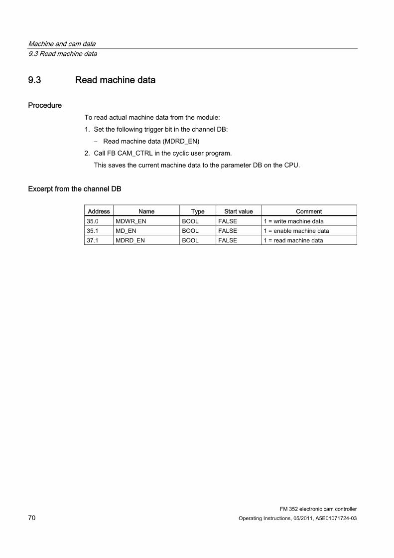
Machine and cam data 9.3 Read machine data
FM 352 electronic cam controller 70 Operating Instructions, 05/2011, A5E01071724-03
9.3 Read machine data
Procedure To read actual machine data from the module:
1. Set the following trigger bit in the channel DB:
– Read machine data (MDRD_EN)
2. Call FB CAM_CTRL in the cyclic user program.
This saves the current machine data to the parameter DB on the CPU.
Excerpt from the channel DB
Address Name Type Start value Comment 35.0 MDWR_EN BOOL FALSE 1 = write machine data 35.1 MD_EN BOOL FALSE 1 = enable machine data 37.1 MDRD_EN BOOL FALSE 1 = read machine data

Machine and cam data 9.4 Writing cam data
FM 352 electronic cam controller Operating Instructions, 05/2011, A5E01071724-03 71
9.4 Writing cam data
Writing cam data Cam data define the type and function principle of the cams and their assignment to the tracks.
Cam data are stored in the parameter DB, starting at address 108.0. These data are grouped in packets, each consisting of 16 cams.
Cam data are active immediately after having been written.
To write cam data without using the programming interface:
1. Enter the new values in the parameter DB.
2. Download the parameter DB to the CPU.
3. Set the trigger bits at the channel DB (CAM1WR_EN to CAM8WR_EN)
4. Call FB CAM_CTRL in the cyclic user program.
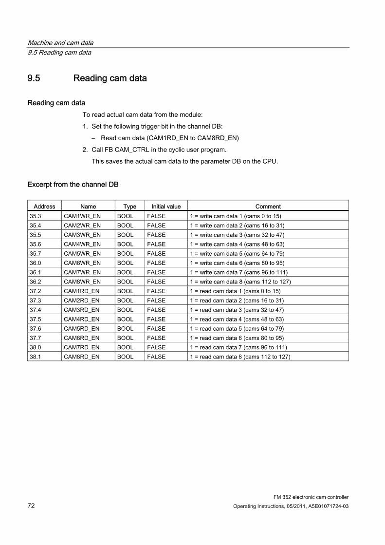
Machine and cam data 9.5 Reading cam data
FM 352 electronic cam controller 72 Operating Instructions, 05/2011, A5E01071724-03
9.5 Reading cam data
Reading cam data To read actual cam data from the module:
1. Set the following trigger bit in the channel DB:
– Read cam data (CAM1RD_EN to CAM8RD_EN)
2. Call FB CAM_CTRL in the cyclic user program.
This saves the actual cam data to the parameter DB on the CPU.
Excerpt from the channel DB
Address Name Type Initial value Comment 35.3 CAM1WR_EN BOOL FALSE 1 = write cam data 1 (cams 0 to 15) 35.4 CAM2WR_EN BOOL FALSE 1 = write cam data 2 (cams 16 to 31) 35.5 CAM3WR_EN BOOL FALSE 1 = write cam data 3 (cams 32 to 47) 35.6 CAM4WR_EN BOOL FALSE 1 = write cam data 4 (cams 48 to 63) 35.7 CAM5WR_EN BOOL FALSE 1 = write cam data 5 (cams 64 to 79) 36.0 CAM6WR_EN BOOL FALSE 1 = write cam data 6 (cams 80 to 95) 36.1 CAM7WR_EN BOOL FALSE 1 = write cam data 7 (cams 96 to 111) 36.2 CAM8WR_EN BOOL FALSE 1 = write cam data 8 (cams 112 to 127) 37.2 CAM1RD_EN BOOL FALSE 1 = read cam data 1 (cams 0 to 15) 37.3 CAM2RD_EN BOOL FALSE 1 = read cam data 2 (cams 16 to 31) 37.4 CAM3RD_EN BOOL FALSE 1 = read cam data 3 (cams 32 to 47) 37.5 CAM4RD_EN BOOL FALSE 1 = read cam data 4 (cams 48 to 63) 37.6 CAM5RD_EN BOOL FALSE 1 = read cam data 5 (cams 64 to 79) 37.7 CAM6RD_EN BOOL FALSE 1 = read cam data 6 (cams 80 to 95) 38.0 CAM7RD_EN BOOL FALSE 1 = read cam data 7 (cams 96 to 111) 38.1 CAM8RD_EN BOOL FALSE 1 = read cam data 8 (cams 112 to 127)
Machine and cam data 9.6 Physical units system
FM 352 electronic cam controller Operating Instructions, 05/2011, A5E01071724-03 73
9.6 Physical units system
Selecting a system of units You can choose a specific system of units for the input and output of data in the parameter assignment interface of the cam controller (default: mm).
You can set any of the following as the system of units:
● mm, inches, degrees, and pulse.
Note
If you change the system of units in the parameter assignment interface under STEP 7, the values are converted to the new system. This may lead to rounding errors.
Values are not converted automatically if you change the system of units via the machine data.
If the system of units is changed from or to "pulses", the cam processing is deactivated, and the axis is no longer synchronized.
System of units in the parameter DB
Address Name Type Initial value Comment 8.0 UNITS DINT L#1 System of units
1 = 10-3 mm 2 = 10-4 inch 3 = 10-4 degrees 4 = 10-2 degrees 5 = pulses 6 = 10-3 degrees
Machine and cam data 9.6 Physical units system
FM 352 electronic cam controller 74 Operating Instructions, 05/2011, A5E01071724-03
Default system of units This manual always specifies limits using mm as the system of units To define the limits in another system of units, convert the values as shown below:
To convert.... you calculate... mm → inch Limit (inch) = limit (mm) × 0.1 1) mm → degrees 10-4 (4 decimal places)
10-3 (3 decimal places) 10-2 (2 decimal places)
Limit (degrees) = limit (mm) × 0.1 Limit (degrees) = limit (mm) × 1 Limit (degrees) = limit (mm) × 10
mm → pulses Limit (pulses) = limit (mm) × 1000
1) The number of post-decimal places affects the number of pre-decimal places for the maximum value. Four post-decimal places are used in the "inch" system of units, which means the maximum entry your can make is 100,000.0000 inch. The "millimeter" system of units uses three post-decimal places, which means the maximum entry you can make is 1,000,000.000 mm.
Machine and cam data 9.7 Machine data of the axis
FM 352 electronic cam controller Operating Instructions, 05/2011, A5E01071724-03 75
9.7 Machine data of the axis
Axis type
Address Name Type Start value Comment 12.0 AXIS_TYPE DINT L#0 Axis type
0 = linear axis 1 = rotary axis
A linear axis has a limited physical traversing range.
A rotary axis is not restricted in its motion range by mechanical limit stops.
Machine and cam data 9.7 Machine data of the axis
FM 352 electronic cam controller 76 Operating Instructions, 05/2011, A5E01071724-03
End of rotary axis
Address Name Type Start value Comment 16.0 ENDROTAX DINT L#100000 End of rotary axis
Range: 1 µm to +1 000 000 000 µm The "end of rotary axis" value is theoretically the highest actual value of the axis. However, the theoretical maximum value is never indicated, because it also represents the physical start position of the rotary axis (= zero). The highest rotary axis value displayed is: End of rotary axis [µm] - resolution [µm / pulse] x 1 [pulse] Example: End of rotary axis = 1000 mm The displayed value jumps: from 999 mm to 0 mm, at a positive rotational direction. from 0 mm to 999 mm, at a negative rotational direction. Rotary axis with absolute encoders The rotary range (0 to end of rotary axis) of an axis with an absolute encoder must correspond exactly to the total number of encoder steps.
Reference point coordinate
Address Name Type Start value Comment 44.0 REFPT DINT L#0 Reference point coordinate
Range: - 1 000 000 000 µm to + 1 000 000 000 µm
Incremental encoder and initiator Using the "Retrigger reference point" function switch and a synchronization event defined by the "Type of reference point retriggering", the reference point coordinate is assigned to this event. Absolute encoder (SSI) An assigned axis with an absolute encoder is always synchronized, provided no error is detected (after transmission of the first error-free SSI frame). For more information, refer to the absolute encoder adjustment description (see chapter "Determining the correct absolute encoder adjustment (Page 82)"), which explains the interaction of the absolute encoder adjustment with the other data. Linear axis The value of the reference point coordinate must always lie within the working range (including the software limit switch start and end). Rotary axis The value of the reference point coordinate must be greater than or equal to 0 and less than the "end of rotary axis" value (0 ≤ reference point coordinate < "End of rotary axis").
Machine and cam data 9.7 Machine data of the axis
FM 352 electronic cam controller Operating Instructions, 05/2011, A5E01071724-03 77
Retrigger reference point:
Address Name Type Initial value Comment 52.0 RETR_TYPE DINT L#0 Type of reference point retriggering
Ranges: 0 = reference point switch and zero mark direction + 1 = reference point switch and zero mark direction - 6 = only reference point switch 7 = only zero mark
By setting the "Type of reference point retriggering", you define the conditions for synchronizing the axis when working with an incremental encoder or an initiator (see chapter "Retrigger reference point (Page 120)").
Machine and cam data 9.7 Machine data of the axis
FM 352 electronic cam controller 78 Operating Instructions, 05/2011, A5E01071724-03
Software limit switch start and end
Address Name Type Initial value Comment 64.0 68.0
SSW_STRT SSW_END
DINT DINT
L# -100 000 000 L# 100 000 000
Software limit switch start Software limit switch end Range: - 1 000 000 000 µm to 1 000 000 000 µm
Those axis data are only of significance to a linear axis. The software limit switches are enabled after the FM 352 is synchronized. The range set by the software limit switches represents the working range. The FM 352 can monitor the working range limits. The software limit switch start (SLS) must always be less than the software limit switch end (SLE).
Absolute encoder (SSI) The FM 352 is synchronized after it has received a complete frame without errors. It monitors the software limit switches as of this time. The absolute encoder used must cover at least the working range (from software limit switch start to software limit switch end, including the limits). Incremental encoder and initiator The axis is initially not synchronized after each restart of the FM 352. The assigned software limit switches are not monitored unless the module has completed a synchronization cycle. Relationship: working range, encoder range, traversing range The "working range" is defined by your task-specific software limit switch settings. The "encoder range" represents the effective encoder range. For linear axes, the module imposes
this range symmetrically across the working range, i.e., it shifts the encoder range in order to equalize the distances between the software limit switches and the ends of the encoder range (see the figure above).
The "traversing range" represents the range of values the FM 352 is capable of processing. It is dependent on the resolution.
The following applies: working range ≥ encoder range ≥ traversing range
Machine and cam data 9.7 Machine data of the axis
FM 352 electronic cam controller Operating Instructions, 05/2011, A5E01071724-03 79
Hysteresis
Address Name Type Initial value Comment 80.0 HYS DINT L#0 Hysteresis
Ranges: 0 to 65 535 [Imp] x resolution [µm/Imp]
The range of values is determined by the resolution: Maximum input value: - to linear axes: max. input value < ¼ of the working range - to rotary axes: max. input value < ¼ of the rotary axis range
Position-based cams and hysteresis A position-based cam is activated if:
● the detected actual value lies within the position-based cam, and
● no hysteresis is set.
Switching points may vary, depending on the position of the direction reversal.
Cam
Hysteresis
1) Cam is activated, as the cam start is crossed in the positive effective direction. 2) The cam remains active due to the hysteresis, irrespective of a direction reversal. 3) At the end of hysteresis, the cam is deactivated. 4) Cam remains deactivated after a direction reversal. 5) The cam is activated again at the end of the hysteresis.
Figure 9-1 Enabling position-based cams with hysteresis
Note
When the direction is reversed, the hysteresis cannot reduce a cam actuation time shorter than the hysteresis.
Machine and cam data 9.7 Machine data of the axis
FM 352 electronic cam controller 80 Operating Instructions, 05/2011, A5E01071724-03
Time-based cam with hysteresis A time-based cam is activated when:
● the cam start is crossed in the effective direction, and
● no hysteresis is set.
Note
The hysteresis will hide a time-based cam if its range between the reversal point and the cam start is less than the hysteresis.
The figure illustrates a time-based cam that is not activated again.
Cams
Hysteresis
1) Cam is activated, as the cam start is crossed in the positive effective direction. 2) After the direction reversal, the cam remains active until the activation time has
expired, regardless of the hysteresis. 3) Cam start is hidden by the hysteresis, the cam is not activated.
Figure 9-2 Activation of a time-based cam with hysteresis
Machine and cam data 9.7 Machine data of the axis
FM 352 electronic cam controller Operating Instructions, 05/2011, A5E01071724-03 81
Simulation velocity
Address Name Type Initial value Comment 84.0 SIM_SPD DINT L#0 Simulation velocity
The simulation velocity depends on the resolution. 0 = standstill 5 ∗ 108 = highest setting supported by the module Within this range, the simulation velocity depends on the resolution: 1000 x resolution ≤ simulation velocity ≤ 3 x 10⁷ x resolution
This machine data determines the simulation velocity (see chapter "Influence of settings on the switching characteristics of time-based cams (Page 103)"). The physical simulation velocity Vsim may deviate from the setting at Vsim, V, and is calculated according to the following formula:
Meaning of this formula: Vsim: Simulation velocity set by the FM 352. Unit: µm/min Vsim, V: Default simulation velocity set in machine data.
Unit: µm/min RES: Resolution derived from encoder data. Unit: µm/pulse Integer ( ): Of this expression, only the value before the decimal point is used for further
calculation. In all calculations, this expression must lie within the range from 2 to 65536. The actual simulation velocity changes abruptly as a result of the relationships (see the formula).
Minimum edge interval
Address Name Type Start value Comment 4.0 EDGEDIST DINT L#0 Minimum edge interval
Range: 0 ... 1 000 000 000 µm
This machine data defines a range after detection of the start of a measurement for an edge detection. The measurement is discarded if the end of the measurement lies within this range. The start of the measurement is not reported unless the minimum edge interval has been traveled.
Machine and cam data 9.8 Determining the correct absolute encoder adjustment
FM 352 electronic cam controller 82 Operating Instructions, 05/2011, A5E01071724-03
9.8 Determining the correct absolute encoder adjustment
Definition The absolute encoder adjustment and reference point coordinate maps the encoder's range of values unambiguously to the axis coordinate system.
Address Name Type Start value Comment 48.0 ENC_ADJ DINT L#0 Absolute encoder adjustment
Range: 0 to (225 -1) The "Absolute encoder adjustment" is used to determine the encoder value corresponding to the reference point coordinate on the axis. The value must be less than the total number of steps of the absolute encoder.
Procedure After you completed the basic program, you need to define a balanced correlation between the encoder and the coordinate system. The procedure shown in the next section is based on the use of the programming interface.
1. Move the axis to a known and physically unambiguous, reproducible point.
This could be the "Software limit switch end".
2. Call the "Set reference point" function, using the coordinate position defined in step 1.
The FM 352 now calculates an encoder value for the reference point coordinate entered in the channel DB (REFPT in channel DB), namely the absolute encoder adjustment. You can view this value at the service screen for of the programming interface.
3. Enter the value from the service screen in the "Absolute encoder adjustment" field on the "Axis" tab of the parameter assignment interface.
4. Save your parameter assignment to the corresponding parameter DB using the export function.
5. Close the parameter assignment interface by selecting File and Exit.
6. In HW Config, download the data to the CPU.
7. Restart the CPU (cold restart) to apply the data.
Note
This adjustment is made once during commissioning. After parameters are assigned, the FM 352 is synchronized during startup as soon as it has received a complete, error-free encoder frame.

Machine and cam data 9.8 Determining the correct absolute encoder adjustment
FM 352 electronic cam controller Operating Instructions, 05/2011, A5E01071724-03 83
Data in the channel DB Address Name Type Start value Comment 98.0 REFPT DINT L#0 Reference point coordinate
Range: - 1 000 000 000 µm to + 1 000 000 000 µm
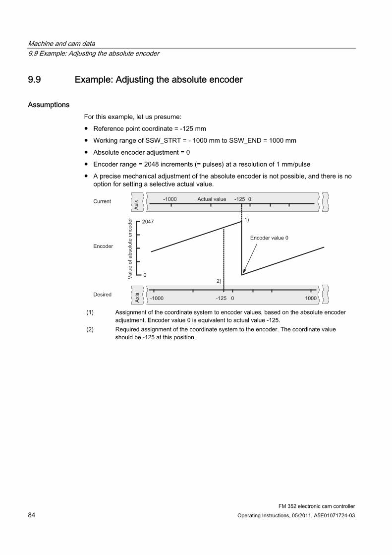
Machine and cam data 9.9 Example: Adjusting the absolute encoder
FM 352 electronic cam controller 84 Operating Instructions, 05/2011, A5E01071724-03
9.9 Example: Adjusting the absolute encoder
Assumptions For this example, let us presume:
● Reference point coordinate = -125 mm
● Working range of SSW_STRT = - 1000 mm to SSW_END = 1000 mm
● Absolute encoder adjustment = 0
● Encoder range = 2048 increments (= pulses) at a resolution of 1 mm/pulse
● A precise mechanical adjustment of the absolute encoder is not possible, and there is no option for setting a selective actual value.
(1) Assignment of the coordinate system to encoder values, based on the absolute encoder
adjustment. Encoder value 0 is equivalent to actual value -125. (2) Required assignment of the coordinate system to the encoder. The coordinate value
should be -125 at this position.
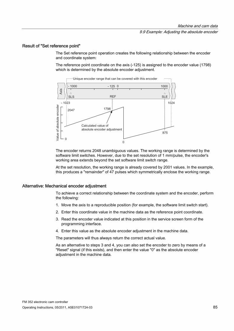
Machine and cam data 9.9 Example: Adjusting the absolute encoder
FM 352 electronic cam controller Operating Instructions, 05/2011, A5E01071724-03 85
Result of "Set reference point" The Set reference point operation creates the following relationship between the encoder and coordinate system:
The reference point coordinate on the axis (-125) is assigned to the encoder value (1798) which is determined by the absolute encoder adjustment.
The encoder returns 2048 unambiguous values. The working range is determined by the software limit switches. However, due to the set resolution of 1 mm/pulse, the encoder's working area extends beyond the set software limit switch range.
At the set resolution, the working range is already covered by 2001 values. In the example, this produces a "remainder" of 47 pulses which symmetrically enclose the working range.
Alternative: Mechanical encoder adjustment To achieve a correct relationship between the coordinate system and the encoder, perform the following:
1. Move the axis to a reproducible position (for example, the software limit switch start).
2. Enter this coordinate value in the machine data as the reference point coordinate.
3. Read the encoder value indicated at this position in the service screen form of the programming interface.
4. Enter this value as the absolute encoder adjustment in the machine data.
The parameters will thus always return the correct actual value.
As an alternative to steps 3 and 4, you can also set the encoder to zero by means of a "Reset" signal (if this exists), and then enter the value "0" as the absolute encoder adjustment in the machine data.
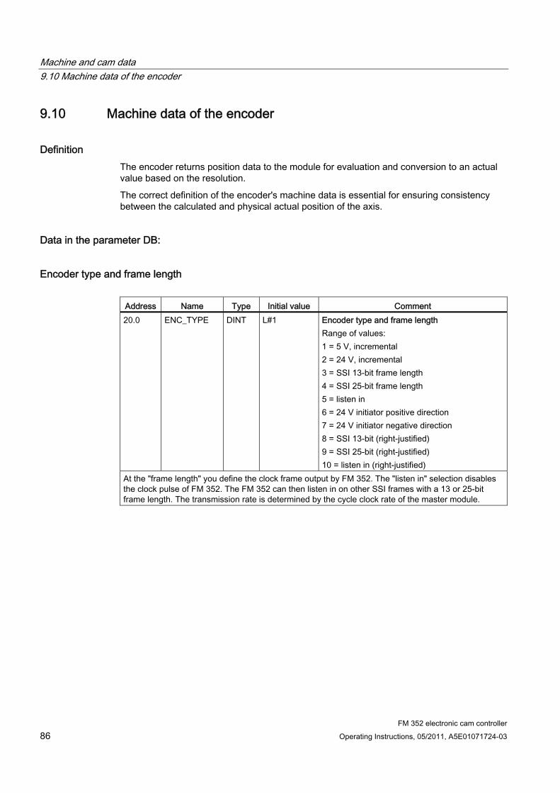
Machine and cam data 9.10 Machine data of the encoder
FM 352 electronic cam controller 86 Operating Instructions, 05/2011, A5E01071724-03
9.10 Machine data of the encoder
Definition The encoder returns position data to the module for evaluation and conversion to an actual value based on the resolution.
The correct definition of the encoder's machine data is essential for ensuring consistency between the calculated and physical actual position of the axis.
Data in the parameter DB:
Encoder type and frame length
Address Name Type Initial value Comment 20.0 ENC_TYPE DINT L#1 Encoder type and frame length
Range of values: 1 = 5 V, incremental 2 = 24 V, incremental 3 = SSI 13-bit frame length 4 = SSI 25-bit frame length 5 = listen in 6 = 24 V initiator positive direction 7 = 24 V initiator negative direction 8 = SSI 13-bit (right-justified) 9 = SSI 25-bit (right-justified) 10 = listen in (right-justified)
At the "frame length" you define the clock frame output by FM 352. The "listen in" selection disables the clock pulse of FM 352. The FM 352 can then listen in on other SSI frames with a 13 or 25-bit frame length. The transmission rate is determined by the cycle clock rate of the master module.
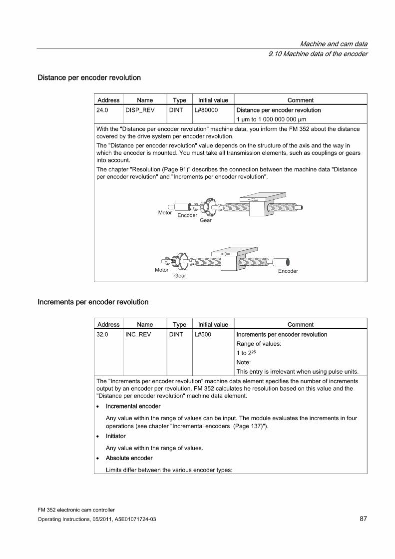
Machine and cam data 9.10 Machine data of the encoder
FM 352 electronic cam controller Operating Instructions, 05/2011, A5E01071724-03 87
Distance per encoder revolution
Address Name Type Initial value Comment 24.0 DISP_REV DINT L#80000 Distance per encoder revolution
1 µm to 1 000 000 000 µm With the "Distance per encoder revolution" machine data, you inform the FM 352 about the distance covered by the drive system per encoder revolution. The "Distance per encoder revolution" value depends on the structure of the axis and the way in which the encoder is mounted. You must take all transmission elements, such as couplings or gears into account. The chapter "Resolution (Page 91)" describes the connection between the machine data "Distance per encoder revolution" and "Increments per encoder revolution".
Increments per encoder revolution
Address Name Type Initial value Comment 32.0 INC_REV DINT L#500 Increments per encoder revolution
Range of values: 1 to 225 Note: This entry is irrelevant when using pulse units.
The "Increments per encoder revolution" machine data element specifies the number of increments output by an encoder per revolution. FM 352 calculates he resolution based on this value and the "Distance per encoder revolution" machine data element. Incremental encoder
Any value within the range of values can be input. The module evaluates the increments in four operations (see chapter "Incremental encoders (Page 137)").
Initiator
Any value within the range of values. Absolute encoder
Limits differ between the various encoder types:
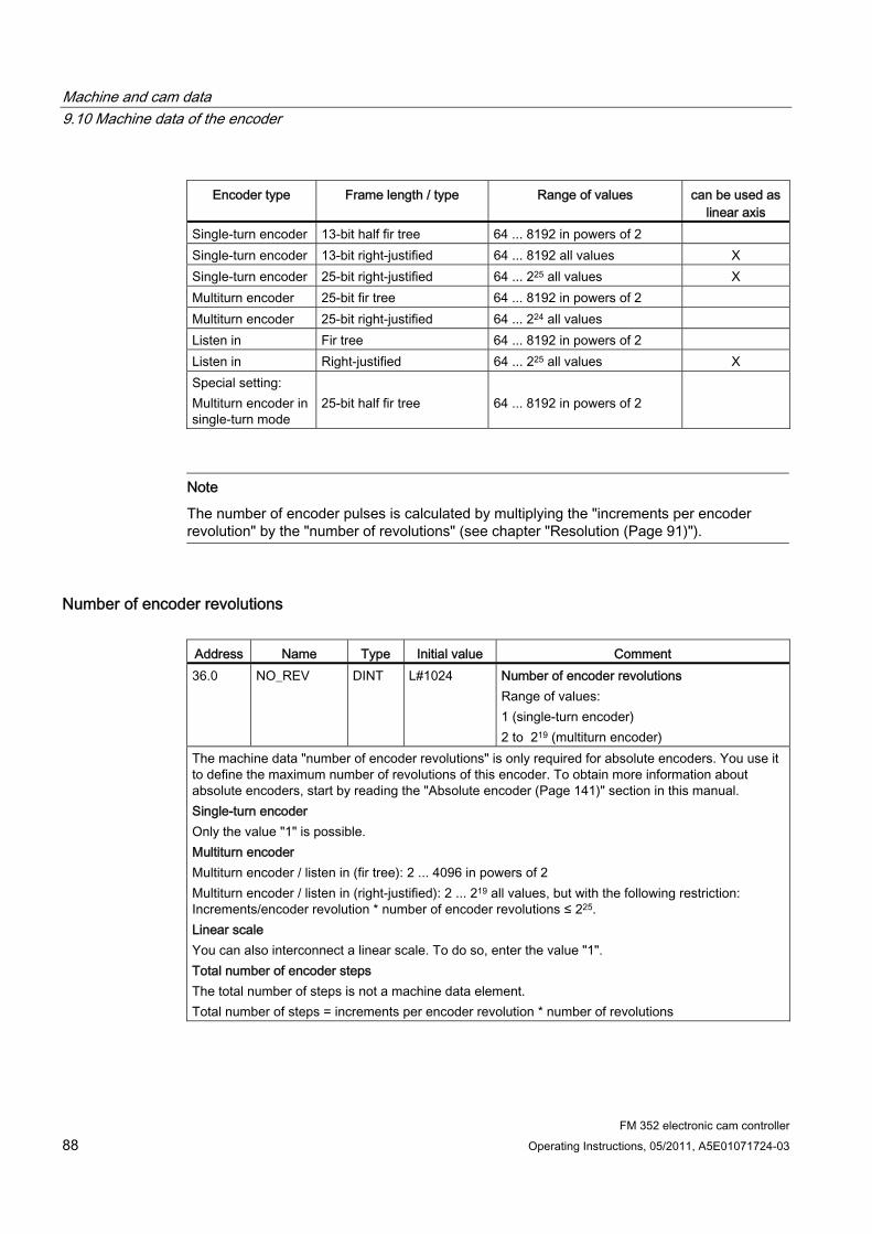
Machine and cam data 9.10 Machine data of the encoder
FM 352 electronic cam controller 88 Operating Instructions, 05/2011, A5E01071724-03
Encoder type Frame length / type Range of values can be used as
linear axis Single-turn encoder 13-bit half fir tree 64 ... 8192 in powers of 2 Single-turn encoder 13-bit right-justified 64 ... 8192 all values X Single-turn encoder 25-bit right-justified 64 ... 225 all values X Multiturn encoder 25-bit fir tree 64 ... 8192 in powers of 2 Multiturn encoder 25-bit right-justified 64 ... 224 all values Listen in Fir tree 64 ... 8192 in powers of 2 Listen in Right-justified 64 ... 225 all values X Special setting: Multiturn encoder in single-turn mode
25-bit half fir tree
64 ... 8192 in powers of 2
Note
The number of encoder pulses is calculated by multiplying the "increments per encoder revolution" by the "number of revolutions" (see chapter "Resolution (Page 91)").
Number of encoder revolutions
Address Name Type Initial value Comment 36.0 NO_REV DINT L#1024 Number of encoder revolutions
Range of values: 1 (single-turn encoder) 2 to 219 (multiturn encoder)
The machine data "number of encoder revolutions" is only required for absolute encoders. You use it to define the maximum number of revolutions of this encoder. To obtain more information about absolute encoders, start by reading the "Absolute encoder (Page 141)" section in this manual. Single-turn encoder Only the value "1" is possible. Multiturn encoder Multiturn encoder / listen in (fir tree): 2 ... 4096 in powers of 2 Multiturn encoder / listen in (right-justified): 2 ... 219 all values, but with the following restriction: Increments/encoder revolution * number of encoder revolutions ≤ 225. Linear scale You can also interconnect a linear scale. To do so, enter the value "1". Total number of encoder steps The total number of steps is not a machine data element. Total number of steps = increments per encoder revolution * number of revolutions
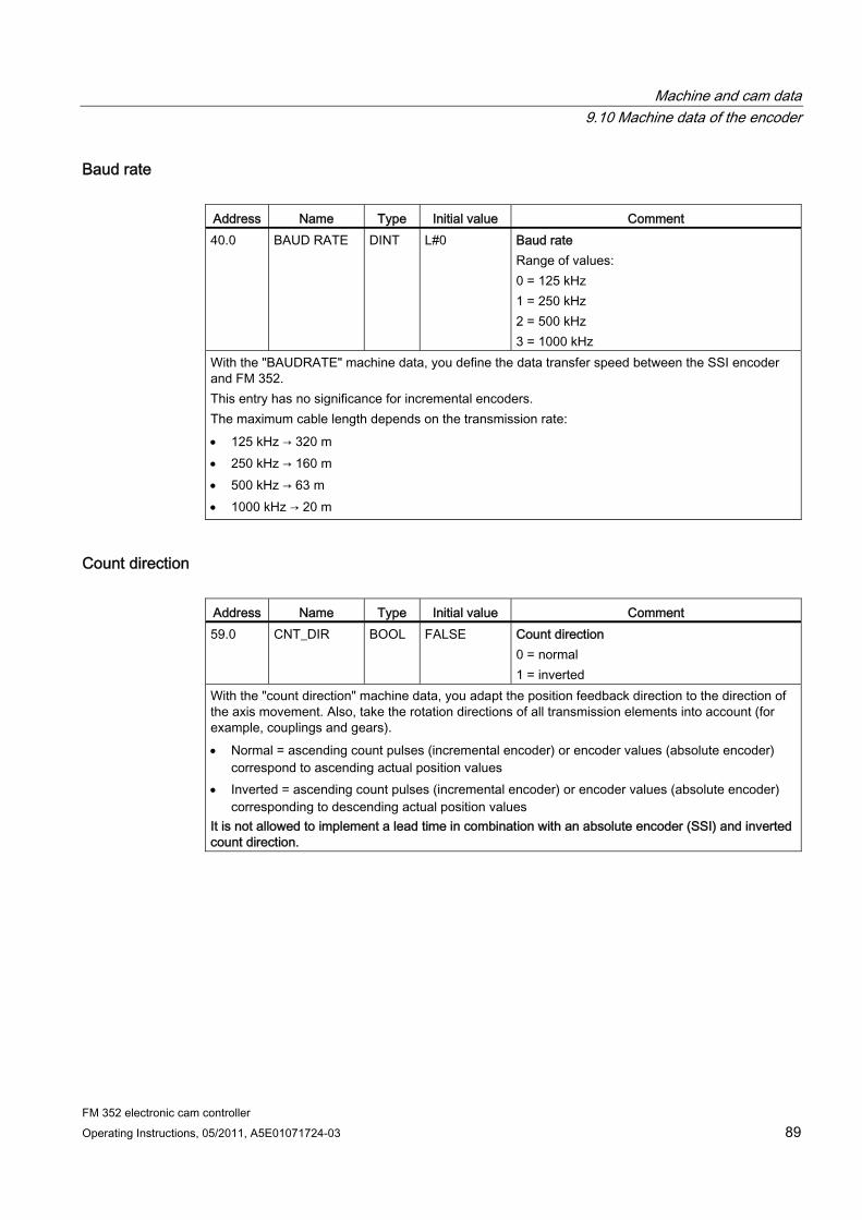
Machine and cam data 9.10 Machine data of the encoder
FM 352 electronic cam controller Operating Instructions, 05/2011, A5E01071724-03 89
Baud rate
Address Name Type Initial value Comment 40.0 BAUD RATE DINT L#0 Baud rate
Range of values: 0 = 125 kHz 1 = 250 kHz 2 = 500 kHz 3 = 1000 kHz
With the "BAUDRATE" machine data, you define the data transfer speed between the SSI encoder and FM 352. This entry has no significance for incremental encoders. The maximum cable length depends on the transmission rate: 125 kHz → 320 m 250 kHz → 160 m 500 kHz → 63 m 1000 kHz → 20 m
Count direction
Address Name Type Initial value Comment 59.0 CNT_DIR BOOL FALSE Count direction
0 = normal 1 = inverted
With the "count direction" machine data, you adapt the position feedback direction to the direction of the axis movement. Also, take the rotation directions of all transmission elements into account (for example, couplings and gears). Normal = ascending count pulses (incremental encoder) or encoder values (absolute encoder)
correspond to ascending actual position values Inverted = ascending count pulses (incremental encoder) or encoder values (absolute encoder)
corresponding to descending actual position values It is not allowed to implement a lead time in combination with an absolute encoder (SSI) and inverted count direction.
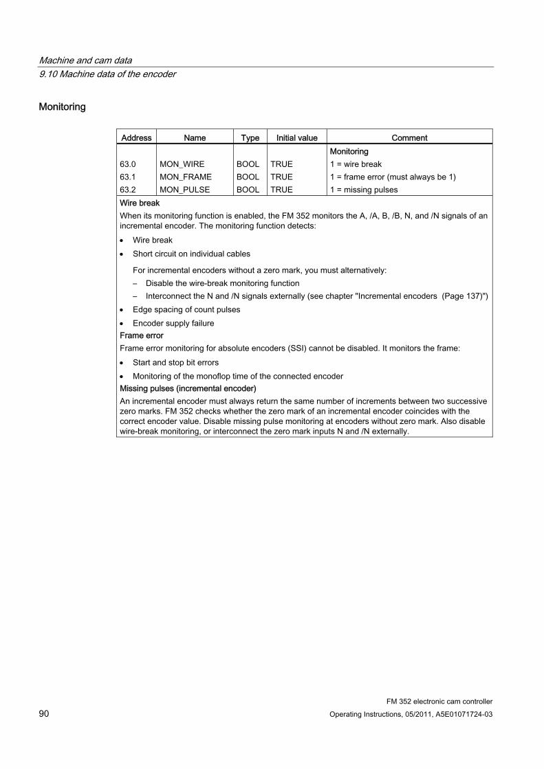
Machine and cam data 9.10 Machine data of the encoder
FM 352 electronic cam controller 90 Operating Instructions, 05/2011, A5E01071724-03
Monitoring
Address Name Type Initial value Comment 63.0 63.1 63.2
MON_WIRE MON_FRAME MON_PULSE
BOOL BOOL BOOL
TRUE TRUE TRUE
Monitoring 1 = wire break 1 = frame error (must always be 1) 1 = missing pulses
Wire break When its monitoring function is enabled, the FM 352 monitors the A, /A, B, /B, N, and /N signals of an incremental encoder. The monitoring function detects: Wire break Short circuit on individual cables
For incremental encoders without a zero mark, you must alternatively: – Disable the wire-break monitoring function – Interconnect the N and /N signals externally (see chapter "Incremental encoders (Page 137)")
Edge spacing of count pulses Encoder supply failure Frame error Frame error monitoring for absolute encoders (SSI) cannot be disabled. It monitors the frame: Start and stop bit errors Monitoring of the monoflop time of the connected encoder Missing pulses (incremental encoder) An incremental encoder must always return the same number of increments between two successive zero marks. FM 352 checks whether the zero mark of an incremental encoder coincides with the correct encoder value. Disable missing pulse monitoring at encoders without zero mark. Also disable wire-break monitoring, or interconnect the zero mark inputs N and /N externally.
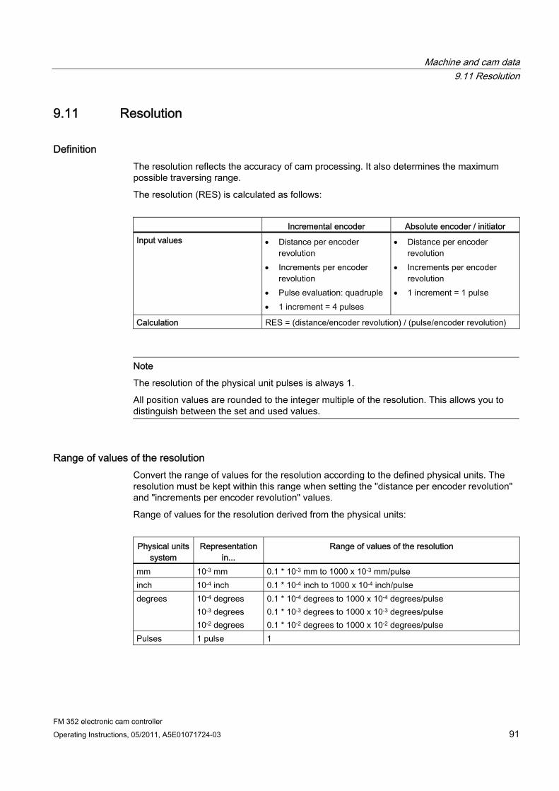
Machine and cam data 9.11 Resolution
FM 352 electronic cam controller Operating Instructions, 05/2011, A5E01071724-03 91
9.11 Resolution
Definition The resolution reflects the accuracy of cam processing. It also determines the maximum possible traversing range.
The resolution (RES) is calculated as follows:
Incremental encoder Absolute encoder / initiator Input values Distance per encoder
revolution Increments per encoder
revolution Pulse evaluation: quadruple 1 increment = 4 pulses
Distance per encoder revolution
Increments per encoder revolution
1 increment = 1 pulse
Calculation RES = (distance/encoder revolution) / (pulse/encoder revolution)
Note
The resolution of the physical unit pulses is always 1.
All position values are rounded to the integer multiple of the resolution. This allows you to distinguish between the set and used values.
Range of values of the resolution Convert the range of values for the resolution according to the defined physical units. The resolution must be kept within this range when setting the "distance per encoder revolution" and "increments per encoder revolution" values.
Range of values for the resolution derived from the physical units:
Physical units
system Representation
in... Range of values of the resolution
mm 10-3 mm 0.1 * 10-3 mm to 1000 x 10-3 mm/pulse inch 10-4 inch 0.1 * 10-4 inch to 1000 x 10-4 inch/pulse degrees 10-4 degrees
10-3 degrees 10-2 degrees
0.1 * 10-4 degrees to 1000 x 10-4 degrees/pulse 0.1 * 10-3 degrees to 1000 x 10-3 degrees/pulse 0.1 * 10-2 degrees to 1000 x 10-2 degrees/pulse
Pulses 1 pulse 1
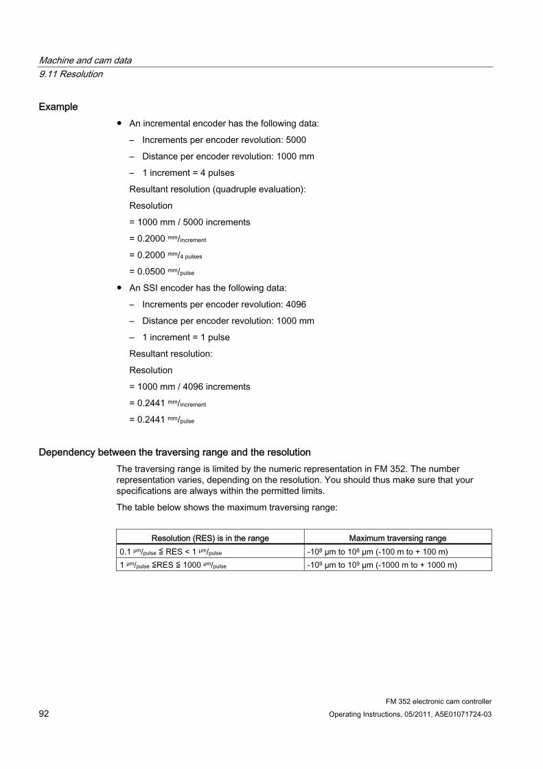
Machine and cam data 9.11 Resolution
FM 352 electronic cam controller 92 Operating Instructions, 05/2011, A5E01071724-03
Example ● An incremental encoder has the following data:
– Increments per encoder revolution: 5000
– Distance per encoder revolution: 1000 mm
– 1 increment = 4 pulses
Resultant resolution (quadruple evaluation):
Resolution
= 1000 mm / 5000 increments
= 0.2000 mm/increment
= 0.2000 mm/4 pulses
= 0.0500 mm/pulse
● An SSI encoder has the following data:
– Increments per encoder revolution: 4096
– Distance per encoder revolution: 1000 mm
– 1 increment = 1 pulse
Resultant resolution:
Resolution
= 1000 mm / 4096 increments
= 0.2441 mm/increment
= 0.2441 mm/pulse
Dependency between the traversing range and the resolution The traversing range is limited by the numeric representation in FM 352. The number representation varies, depending on the resolution. You should thus make sure that your specifications are always within the permitted limits.
The table below shows the maximum traversing range:
Resolution (RES) is in the range Maximum traversing range
0.1 µm/pulse ≦ RES < 1 µm/pulse -108 µm to 108 µm (-100 m to + 100 m) 1 µm/pulse ≦RES ≦ 1000 µm/pulse -109 µm to 109 µm (-1000 m to + 1000 m)
Machine and cam data 9.11 Resolution
FM 352 electronic cam controller Operating Instructions, 05/2011, A5E01071724-03 93
Dependency between the velocity and resolution The velocity indicated may vary within the following limits, depending on the resolution (data relate to mm units):
● from 1 µm/min to 90 m/min, at a resolution < 1 µm/pulse
● from 1 µm/min to 900 m/min, at a resolution ≥ 1 µm/pulse
The velocity value is calculated and filtered by the module at intervals of 4 ms.
Its minimum inaccuracy of one pulse/4 ms rules it out for closed-loop control.
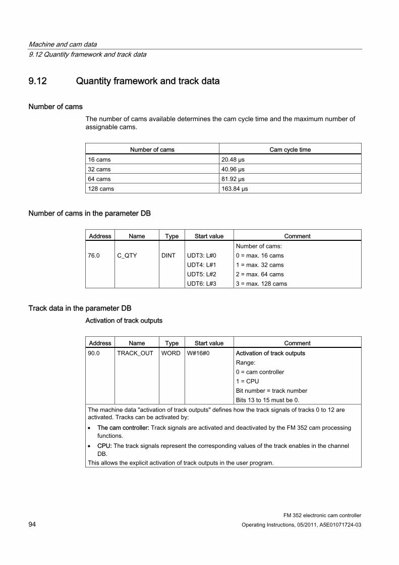
Machine and cam data 9.12 Quantity framework and track data
FM 352 electronic cam controller 94 Operating Instructions, 05/2011, A5E01071724-03
9.12 Quantity framework and track data
Number of cams The number of cams available determines the cam cycle time and the maximum number of assignable cams.
Number of cams Cam cycle time
16 cams 20.48 µs 32 cams 40.96 µs 64 cams 81.92 µs 128 cams 163.84 µs
Number of cams in the parameter DB
Address Name Type Start value Comment 76.0
C_QTY
DINT
UDT3: L#0 UDT4: L#1 UDT5: L#2 UDT6: L#3
Number of cams: 0 = max. 16 cams 1 = max. 32 cams 2 = max. 64 cams 3 = max. 128 cams
Track data in the parameter DB Activation of track outputs
Address Name Type Start value Comment 90.0 TRACK_OUT WORD W#16#0 Activation of track outputs
Range: 0 = cam controller 1 = CPU Bit number = track number Bits 13 to 15 must be 0.
The machine data "activation of track outputs" defines how the track signals of tracks 0 to 12 are activated. Tracks can be activated by: The cam controller: Track signals are activated and deactivated by the FM 352 cam processing
functions. CPU: The track signals represent the corresponding values of the track enables in the channel
DB. This allows the explicit activation of track outputs in the user program.
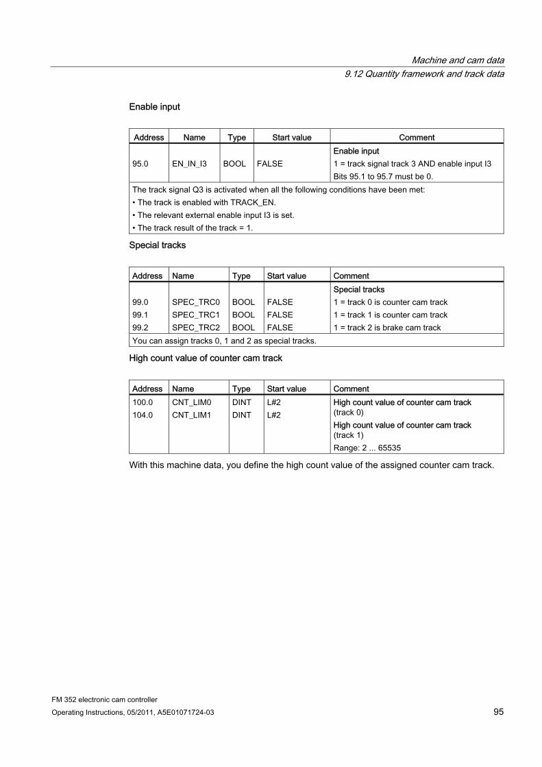
Machine and cam data 9.12 Quantity framework and track data
FM 352 electronic cam controller Operating Instructions, 05/2011, A5E01071724-03 95
Enable input
Address Name Type Start value Comment 95.0
EN_IN_I3
BOOL
FALSE
Enable input 1 = track signal track 3 AND enable input I3 Bits 95.1 to 95.7 must be 0.
The track signal Q3 is activated when all the following conditions have been met: • The track is enabled with TRACK_EN. • The relevant external enable input I3 is set. • The track result of the track = 1.
Special tracks
Address Name Type Start value Comment 99.0 99.1 99.2
SPEC_TRC0 SPEC_TRC1 SPEC_TRC2
BOOL BOOL BOOL
FALSE FALSE FALSE
Special tracks 1 = track 0 is counter cam track 1 = track 1 is counter cam track 1 = track 2 is brake cam track
You can assign tracks 0, 1 and 2 as special tracks.
High count value of counter cam track
Address Name Type Start value Comment 100.0 104.0
CNT_LIM0 CNT_LIM1
DINT DINT
L#2 L#2
High count value of counter cam track (track 0) High count value of counter cam track (track 1) Range: 2 ... 65535
With this machine data, you define the high count value of the assigned counter cam track.

Machine and cam data 9.13 Interrupt enable
FM 352 electronic cam controller 96 Operating Instructions, 05/2011, A5E01071724-03
9.13 Interrupt enable
Definition In the cam data, you can specify whether hardware interrupts are to be generated when cams 0 to 7 are activated and/or deactivated (see chapter "Cam data (Page 97)").
Machine data for interrupt enable in the parameter DB
Address Absolute
Name Type Start value Comment
3.2 PI_CAM BOOL FALSE 1 = enable hardware interrupt: cam on/off
Cam data for interrupt enable in the parameter DB
Address relative
Name Type Start value Comment
+0.4 PI_SW_ON BOOL FALSE 1 = hardware interrupt on activation +0.5 PI_SW_OFF BOOL FALSE 1 = hardware interrupt on deactivation

Machine and cam data 9.14 Cam data
FM 352 electronic cam controller Operating Instructions, 05/2011, A5E01071724-03 97
9.14 Cam data
Definition Cam data describe the properties of a cam, the assignment of each cam to a track, and the switching characteristic of the cam. The cam data listed below are set separately at each cam.
● The module interprets and processes only the cams with "valid" settings.
● Cams 0 to 7 support hardware interrupts.
● The number of assignable cams depends on the number of cams available.
Switching characteristics of cams based on their effective direction A positive effective direction is always assumed, with the exception of example 5.
No. Description Position-based cam Time-based cam
1 A cam is traversed in the effective direction
2 A cam is traversed in reversed effective direction
3 A cam is approached in effective direction; the motion direction of the axis is reversed while the cam is active
4 A cam is approached in reversed effective direction; the axis reverses its direction of movement on the cam in effective direction
Cam not switched
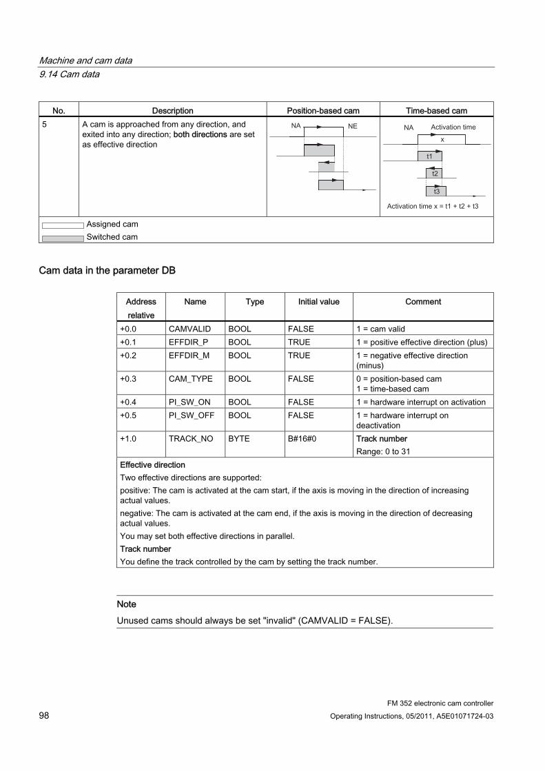
Machine and cam data 9.14 Cam data
FM 352 electronic cam controller 98 Operating Instructions, 05/2011, A5E01071724-03
No. Description Position-based cam Time-based cam 5 A cam is approached from any direction, and
exited into any direction; both directions are set as effective direction
Assigned cam Switched cam
Cam data in the parameter DB
Address relative
Name Type Initial value Comment
+0.0 CAMVALID BOOL FALSE 1 = cam valid +0.1 EFFDIR_P BOOL TRUE 1 = positive effective direction (plus) +0.2 EFFDIR_M BOOL TRUE 1 = negative effective direction
(minus) +0.3 CAM_TYPE BOOL FALSE 0 = position-based cam
1 = time-based cam +0.4 PI_SW_ON BOOL FALSE 1 = hardware interrupt on activation +0.5 PI_SW_OFF BOOL FALSE 1 = hardware interrupt on
deactivation +1.0 TRACK_NO BYTE B#16#0 Track number
Range: 0 to 31 Effective direction Two effective directions are supported: positive: The cam is activated at the cam start, if the axis is moving in the direction of increasing actual values. negative: The cam is activated at the cam end, if the axis is moving in the direction of decreasing actual values. You may set both effective directions in parallel. Track number You define the track controlled by the cam by setting the track number.
Note
Unused cams should always be set "invalid" (CAMVALID = FALSE).
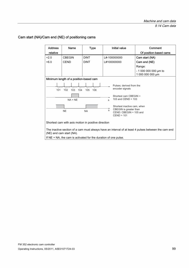
Machine and cam data 9.14 Cam data
FM 352 electronic cam controller Operating Instructions, 05/2011, A5E01071724-03 99
Cam start (NA)/Cam end (NE) of positioning cams
Address relative
Name Type Initial value Comment Of position-based cams
+2.0 +6.0
CBEGIN CEND
DINT DINT
L#-100000000 L#100000000
Cam start (NA) Cam end (NE) Range: - 1 000 000 000 µm to 1 000 000 000 µm
Minimum length of a position-based cam
Shortest cam with axis motion in positive direction
The inactive section of a cam must always have an interval of at least 4 pulses between the cam end (NE) and cam start (NA). If NE = NA, the cam is activated for the duration of one pulse.
Machine and cam data 9.14 Cam data
FM 352 electronic cam controller 100 Operating Instructions, 05/2011, A5E01071724-03
Cam start (NA)/Cam end (NE) for time-based cam
Address relative
Name Type Initial value Comment of time cams
+2.0 +6.0
CBEGIN CEND
DINT DINT
L#-100000000 L#100000000
Cam start (NA) Cam end (NE) Activation time Range: (0 to 13421) x 100 µs with up to 16 cams (0 to 26843) x 100 µs with up to 32 cams (0 to 53686) x 100 µs with up to 64 cams (0 to 65535) x 100 µs with up to 128 cams
With a time-based cam, you must specify a cam start and an activation time in place of the cam end. You can set a resolution of 100 µs for the activation time. The time runs starting with the activation of the cam. Conditions of setting default times: 0 µs: A cam with 0 µs activation time is never activated 0 µs < t ≤ 400 µs: The FM 352 sets a minimum cam activation time of approx. 330 µs. t > 400 µs: FM 352 calculates the actual activation time tact based on the default activation time
tdef according to this formula:
The maximum error is always less than the cam cycle time.
Machine and cam data 9.14 Cam data
FM 352 electronic cam controller Operating Instructions, 05/2011, A5E01071724-03 101
Lead time Address relative
Name Type Initial value Comment
+ 10.0 LTIME INT 0 Lead time Range: (0 to 53686) x 100 µs with max. 16 cams (0 to 65535) x 100 µs with max. 32, 64 or 128 cams
You can compensate any delays caused by the connected switchgear by setting a lead time. Define the lead time with a resolution of 100 µs. You can assign one lead time to each cam. The lead time applies to the cam start and cam end. Anticipation distance The anticipation distance of a cam is calculated continuously based on the current velocity and lead time. The entire cam is shifted in direction of the actual value by this distance. The assigned range is the "static range", and the range calculated based on the lead time is the "dynamic range". Anticipation distance = [lead time] x [current velocity] FM 352 calculates the anticipation distances of all cams within 1/4 of the longest assigned lead time. A very high lead time setting for a cam reduces the frequency of the dynamic adjustment calculation. Actual lead time To calculate the actual lead time: Determine the cam cycle time: This is the time that the FM 352 requires to complete processing of all cams. It depends on the number of cams available. Calculate the actual lead time based on the following formula:
The identifiers have the following meanings: Lead time act is the lead time set by the FM 352 Lead time d is your default setting. Integer ( ) means that the values after the decimal point are ignored in the calculation of the parenthesis. The maximum error of the lead timeact is always < [cam cycle time] x 4. Example: The following values are defined: Number of cams: maximum of 32 cams Cam cycle time: 40.96 µs Lead timeV = 1000 µs Result: The result is an actual lead time of 983 µs It is not allowed to implement a lead time in combination with an absolute encoder (SSI) and inverted count direction.

Machine and cam data 9.14 Cam data
FM 352 electronic cam controller 102 Operating Instructions, 05/2011, A5E01071724-03
Note
The actual lead time is always less than the assigned lead time. It may be 0, even though the assigned lead time ≥100 µs.
The anticipation distance of a rotary axis must be less than the rotary axis range and the inactive part of the cam. This must be ensured for all velocities.
Dynamic cam adjustment There are two distinct situations relating to the cam range:
1. The static and dynamic range of the cam overlap.
2. The static and dynamic range of the cam do not overlap.
Table 9- 1 Dynamic cam adjustment (different use cases)
Dynamic adjustment Description If the dynamic range of the cam overlaps its static range:
The cam is activated when its dynamic range is reached. At the same time, calculation of a new dynamic adjustment is disabled.
When the actual value reaches the static range of the cam, the calculation of a new dynamic adjustment is enabled again. A change in velocity affects the cam end.
When the cam is deactivated at the end of the dynamic range, dynamic adjustment will be disabled again until the end of the static range of the cam.
If the cam's dynamic and static ranges do not overlap: The cam is activated when its dynamic range is reached.
At the same time, calculation of a new dynamic adjustment is disabled.
At the end of the static range of the cam, dynamic adjustment is enabled again.
Dynamic range Static range A new dynamic adjustment is possible
Note
When the direction of rotation changes, calculation of the dynamic adjustment is enabled again.
FM 352 electronic cam controller Operating Instructions, 05/2011, A5E01071724-03 103
Settings 1010.1 Influence of settings on the switching characteristics of time-based
cams
Actual value changes A time cam can be skipped by the following settings that change the actual value:
● Set actual value
● Set actual value on-the-fly
● Zero offset
● Retrigger reference point
Activating a time-based cam If you skip the start of a time-based cam due to one of the settings listed above, this cam is activated provided the actual direction of the axis motion is the same as the effective direction assigned for the cam. The assigned activation time starts.
Note
If the axis is at a standstill, the direction of movement is influenced by fluctuations of the actual value.
If you want the direction of movement to be taken into account when the axis is at a standstill, you must set a hysteresis that is greater than the fluctuations in the actual value when the axis is at a standstill.
This retains the last determined direction of movement while the axis is at a standstill.
WARNING Risk of injury and material damage.
Any modification of the actual value at rotary axes may cause the unwanted activation of time-based cams.
You should always set the "invalid" option at the time-based cams of a rotary axis if you want to influence the actual value using the settings mentioned earlier.

Settings 10.2 Set Actual Value/Set Actual Value on-the-fly/Cancel Set Actual Value
FM 352 electronic cam controller 104 Operating Instructions, 05/2011, A5E01071724-03
10.2 Set Actual Value/Set Actual Value on-the-fly/Cancel Set Actual Value
Definition You program the "Set actual value/Set actual value on-the-fly" settings in order to assign a new coordinate to the actual encoder value. This shifts the coordinate system by the value: ACTnew - ACTcurrent
Whereby:
● ACTnew is the default value
● ACTcurrent is the actual value at the time of execution
Determining new coordinates Calculate all your default positions in the shifted coordinate system based on the following formula:
Coordinatenew = Coordinateold + (ACTnew - ACTcurrent)
Requirements ● The axis must be synchronized.
● With "set actual value on-the-fly": Digital input I1 must be interconnected.
Programming steps 1. Enter the coordinate for the actual value, or for the actual value to set on-the-fly in the
channel DB.
– Linear axis:
Select an actual value so that the software limit switches are still within the permissible traversing range after the setting is called.
The absolute value of the offset derived from (ACTnew - ACTcurrent) must be less than or equal to the absolute value of the permitted traversing range (maximum 100 m or 1000 m).
– Rotary axis:
Rule for the defined actual value:
0 ≤ actual value < end of rotary axis
2. Set the appropriate trigger bits at the channel DB.
3. Call the FB CAM_CTRL.
"Set actual values" is executed immediately.
"Set actual value on-the-fly" is executed at the next positive edge at digital input I1. The FVAL_DONE bit is set.

Settings 10.2 Set Actual Value/Set Actual Value on-the-fly/Cancel Set Actual Value
FM 352 electronic cam controller Operating Instructions, 05/2011, A5E01071724-03 105
Data used in the channel DB
Address Name Type Initial value Comment 36.4 AVAL_EN BOOL FALSE 1 = set actual value 36.5 FVAL_EN BOOL FALSE 1 = set actual value on-the-fly 90.0 AVAL DINT L#0 Actual value coordinate 94.0 FVAL DINT L#0 Coordinate for on-the-fly actual value 25.5 FVAL_DONE BOOL FALSE 1 = set actual value on-the-fly executed
Effects of the setting Based on the example "set actual value" to 400 mm (at position 200 mm), you can see how this setting shifts the coordinate system. Resultant effects:
● The position of the working range is not physically shifted.
● The various points, such as the software limit switches, are assigned new coordinate values.
● The cams retain their coordinate values, and are therefore located at a different physical position.
● When the axis is synchronized and the cam processing is enabled, the actual position may skip cam edges or complete cams as a result of this setting.
● Status changes of the cam which would normally trigger an interrupt may be lost.
Note
For information on switching characteristics of time-based cams, refer to chapter "Influence of settings on the switching characteristics of time-based cams (Page 103)".

Settings 10.2 Set Actual Value/Set Actual Value on-the-fly/Cancel Set Actual Value
FM 352 electronic cam controller 106 Operating Instructions, 05/2011, A5E01071724-03
Table 10- 1 Shift of the coordinate system by "Set Actual Value" / "Set Actual Value on-the-Fly"
Set actual value SLS [mm]
REF [mm]
ACT [mm]
SLE [mm]
-400
-200
200
400
-200
0
400
600
Canceling the setting The "Cancel set actual value" can be used to reset the coordinate shift caused by "Set actual value" or "Set actual value on-the-fly".
Once "set actual value on-the-fly" has been triggered, it can no longer be deleted before execution by a positive edge at input I1. However, it can be overwritten by a new "Set actual value on-the-fly".
These settings will be reset at the next start of the module.
Parameter used in the channel DB
Address Name Type Start value Comment 35.2 AVALREM_EN BOOL FALSE 1: Cancel actual value setting
Possible causes of error "Set actual value on-the-fly" and "Retrigger reference point" may not be executed in parallel.
The "set actual value on-the-fly" can be monitored in order to signal an operating error if this setting causes a software limit switch to exceed the permissible traversing range at a positive edge at input I1. This operating error is signaled by a diagnostic interrupt, and written to the diagnostic buffer.
Settings 10.3 Set zero offset
FM 352 electronic cam controller Operating Instructions, 05/2011, A5E01071724-03 107
10.3 Set zero offset
Definition The "zero offset" setting lets you shift the zero position in the coordinate system by a defined value. The sign determines the offset direction.
Determining a new coordinate All values of the shifted coordinate system can be calculated according to the following formula:
Coordinatenew = Coordinateold - (ZPOnew - ZPOold)
ZPOold identifies any existing zero offset. If no zero offset was active prior to the call, set a 0 value at ZPOold.
Based on this formula, you can calculate the coordinates for the software limit switches, for example.
Programming steps 1. Write the zero offset value to the channel DB.
– Linear axis:
The zero offset must be selected so that the software limit switches remain within the permissible traversing range after the setting is called.
– Rotary axis:
Rule for the zero offset:
value of zero offset ≤ end of the rotary axis.
2. Set the relevant trigger bit.

Settings 10.3 Set zero offset
FM 352 electronic cam controller 108 Operating Instructions, 05/2011, A5E01071724-03
Data used in the channel DB
Address Name Type Initial value Comment 36.6 ZOFF_EN BOOL FALSE 1 = set zero offset 86.0 ZOFF DINT L#0 Zero offset
Effects on a linear axis Based on the example of a zero offset of -200 mm, you can see that this setting shifts the coordinate system in positive direction. Resultant effects:
● The working range is not physically shifted.
● The various points, such as the software limit switches, are assigned new coordinate values.
● The cams retain their coordinate values, and are therefore located at a different physical position.
● When the axis is synchronized and the cam processing is enabled, the actual position may skip cam edges or complete cams as a result of this setting.
● Status changes of the cam which would normally trigger an interrupt may be lost.
Table 10- 2 Coordinate system shift as a result of zero offset
Zero offset SLS [mm]
REF [mm]
ACT [mm]
SLE [mm]
-400
-200
200
400
-200
0
400
600
Note
For information on switching characteristics of time-based cams, refer to chapter "Influence of settings on the switching characteristics of time-based cams (Page 103)".

Settings 10.3 Set zero offset
FM 352 electronic cam controller Operating Instructions, 05/2011, A5E01071724-03 109
Effects on a rotary axis Based on the example of a zero offset by -45° , you can see how this setting rotates the coordinate system:
Table 10- 3 Rotation of the coordinate system as a result of zero offset
Tool at ACT = 340° Tool when ACT = 25°
The zero position rotates by - 45 degrees. All axis points are assigned new coordinate values.
Including a ZPOold = 0, the result is a new value of 385°
As actual value resumes at 0 at the end of the rotary axis operating in positive directional rotation, the calculation returns an actual value of 25°:
Coordinatenew = Coordinateold - (ZPOnew - ZPOold) - end of rotary axis
The end of rotary axis value only needs to be subtracted when
Coordinateold - (ZPOnew - NPVold) is greater than the end of rotary axis.
Loss of synchronization If synchronization is lost due to an error, or reset due to "retrigger reference point", a zero offset is retained.
Canceling a setting A zero offset of 0 resets any existing offset.
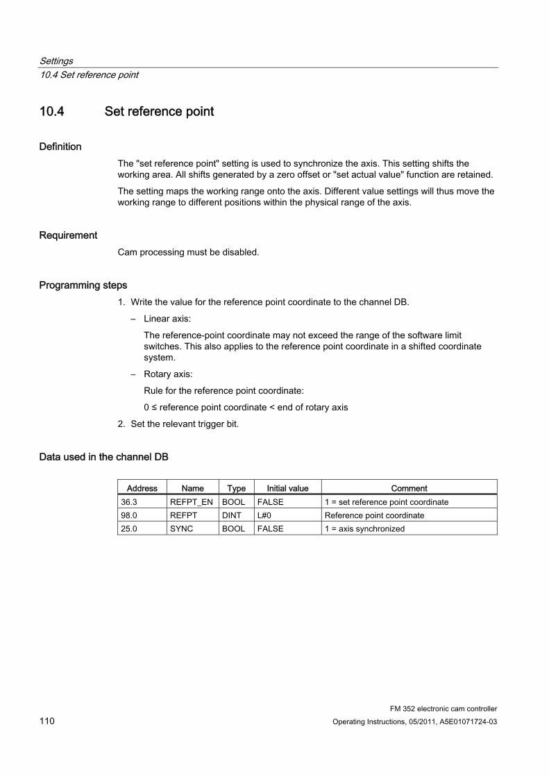
Settings 10.4 Set reference point
FM 352 electronic cam controller 110 Operating Instructions, 05/2011, A5E01071724-03
10.4 Set reference point
Definition The "set reference point" setting is used to synchronize the axis. This setting shifts the working area. All shifts generated by a zero offset or "set actual value" function are retained.
The setting maps the working range onto the axis. Different value settings will thus move the working range to different positions within the physical range of the axis.
Requirement Cam processing must be disabled.
Programming steps 1. Write the value for the reference point coordinate to the channel DB.
– Linear axis:
The reference-point coordinate may not exceed the range of the software limit switches. This also applies to the reference point coordinate in a shifted coordinate system.
– Rotary axis:
Rule for the reference point coordinate:
0 ≤ reference point coordinate < end of rotary axis
2. Set the relevant trigger bit.
Data used in the channel DB
Address Name Type Initial value Comment 36.3 REFPT_EN BOOL FALSE 1 = set reference point coordinate 98.0 REFPT DINT L#0 Reference point coordinate 25.0 SYNC BOOL FALSE 1 = axis synchronized
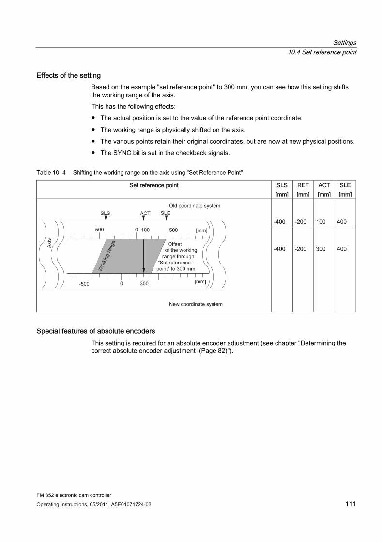
Settings 10.4 Set reference point
FM 352 electronic cam controller Operating Instructions, 05/2011, A5E01071724-03 111
Effects of the setting Based on the example "set reference point" to 300 mm, you can see how this setting shifts the working range of the axis.
This has the following effects:
● The actual position is set to the value of the reference point coordinate.
● The working range is physically shifted on the axis.
● The various points retain their original coordinates, but are now at new physical positions.
● The SYNC bit is set in the checkback signals.
Table 10- 4 Shifting the working range on the axis using "Set Reference Point"
Set reference point SLS [mm]
REF [mm]
ACT [mm]
SLE [mm]
-400
-200
100
400
-400
-200
300
400
Special features of absolute encoders This setting is required for an absolute encoder adjustment (see chapter "Determining the correct absolute encoder adjustment (Page 82)").
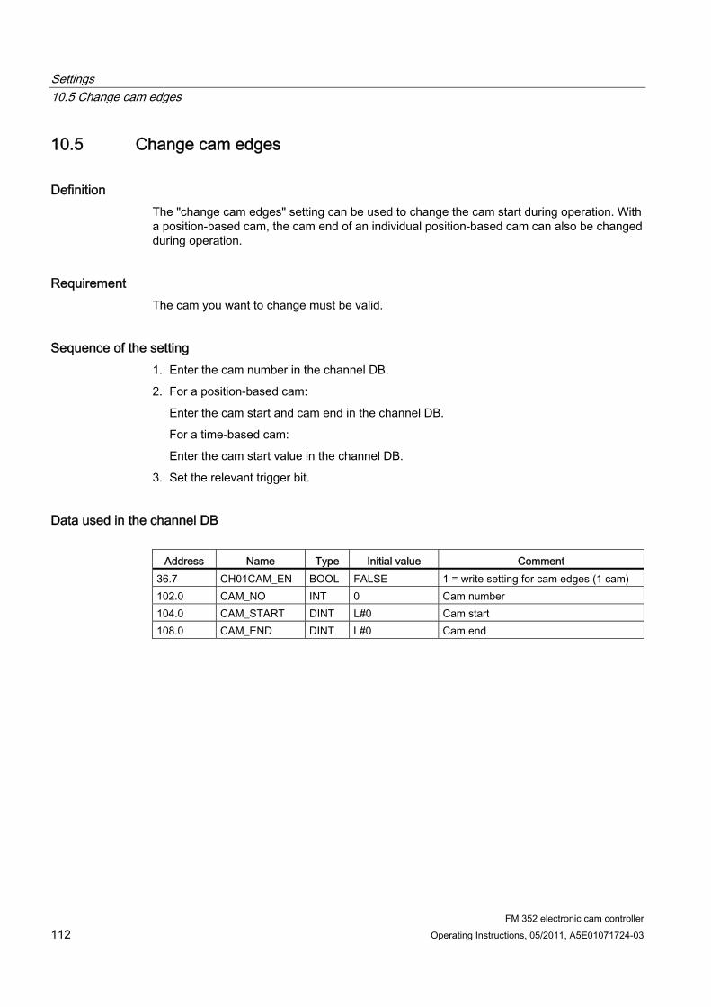
Settings 10.5 Change cam edges
FM 352 electronic cam controller 112 Operating Instructions, 05/2011, A5E01071724-03
10.5 Change cam edges
Definition The "change cam edges" setting can be used to change the cam start during operation. With a position-based cam, the cam end of an individual position-based cam can also be changed during operation.
Requirement The cam you want to change must be valid.
Sequence of the setting 1. Enter the cam number in the channel DB.
2. For a position-based cam:
Enter the cam start and cam end in the channel DB.
For a time-based cam:
Enter the cam start value in the channel DB.
3. Set the relevant trigger bit.
Data used in the channel DB
Address Name Type Initial value Comment 36.7 CH01CAM_EN BOOL FALSE 1 = write setting for cam edges (1 cam) 102.0 CAM_NO INT 0 Cam number 104.0 CAM_START DINT L#0 Cam start 108.0 CAM_END DINT L#0 Cam end
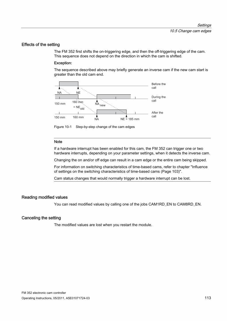
Settings 10.5 Change cam edges
FM 352 electronic cam controller Operating Instructions, 05/2011, A5E01071724-03 113
Effects of the setting The FM 352 first shifts the on-triggering edge, and then the off-triggering edge of the cam. This sequence does not depend on the direction in which the cam is shifted.
Exception:
The sequence described above may briefly generate an inverse cam if the new cam start is greater than the old cam end.
Figure 10-1 Step-by-step change of the cam edges
Note
If a hardware interrupt has been enabled for this cam, the FM 352 can trigger one or two hardware interrupts, depending on your parameter settings, when it detects the inverse cam.
Changing the on and/or off edge can result in a cam edge or the entire cam being skipped.
For information on switching characteristics of time-based cams, refer to chapter "Influence of settings on the switching characteristics of time-based cams (Page 103)".
Cam status changes that would normally trigger a hardware interrupt can be lost.
Reading modified values You can read modified values by calling one of the jobs CAM1RD_EN to CAM8RD_EN.
Canceling the setting The modified values are lost when you restart the module.
Settings 10.6 Perform "Fast Cam Parameter Change"
FM 352 electronic cam controller 114 Operating Instructions, 05/2011, A5E01071724-03
10.6 Perform "Fast Cam Parameter Change"
Definition The "Fast cam parameter change" setting can be used to modify a group of up to 16 cams while the system is in RUN.
Requirement The cams you want to modify must be valid.
Programming steps 1. Enter the number of cams to be modified in the channel DB.
2. Enter the number of the first cam to be modified in the channel DB.
3. Set the trigger bits for the required modifications.
4. Declare the new values at the channel DB.
5. Repeat steps 2 to 4 for each cam to be modified.
6. Set the relevant trigger bit in the channel DB.
Data used in the channel DB
Address Absolute
Name Type Start value
Comment
37.0 CH16CAM_EN BOOL FALSE 1 = write fast cam parameter change settings (16 cams)
176.0 C_QTY BYTE B#16#0 Number of cams to modify 177.0 DIS_CHECK BOOL FALSE 1 = disable data check
Address relative
Name Type Start value
Comment
+0.0 CAM_NO BYTE B#16#0 Number of the cam to modify +1.0 C_EFFDIR BOOL FALSE 1 = change the effective direction of the cam +1.1 C_CBEGIN BOOL FALSE 1 = change the cam start to the value
CBEGIN +1.2 C_CEND BOOL FALSE 1 = change the cam end / activation time to
the value CEND +1.3 C_LTIME BOOL FALSE 1 = change the lead time to the value in
LTIME +1.4 CAM_OFF BOOL FALSE 1 = deactivate the cam during the cam
modification +1.5 EFFDIR_P BOOL FALSE 1 = positive effective direction (plus)
Settings 10.6 Perform "Fast Cam Parameter Change"
FM 352 electronic cam controller Operating Instructions, 05/2011, A5E01071724-03 115
Address relative
Name Type Start value
Comment
+1.6 EFFDIR_M BOOL FALSE 1 = negative effective direction (minus) +2.0 CBEGIN DINT L#0 New cam start +6.0 CEND DINT L#0 New cam end / new activation time +10.0 LTIME INT L#0 New lead time
Deactivating a cam when making modifications To maintain consistency, always deactivate the cam (CAM_OFF) when you modify the cam start and cam end settings.
Data check by the module With the DIS_CHECK (channel DB) parameter, you specify whether the check of transferred data by the FM 352 is to be disabled. If you disable the data check, you must take steps to verify that only permitted values are transferred. If you transfer illegal values without a check, the module can behave unexpectedly.
● FALSE: The module checks all data to be transferred
● TRUE: The check of cam parameter data is disabled. This allows the faster integration of the data to be changed on the FM 352.
Regardless of this setting, the module always checks whether
– the axis is assigned
– the number of cams to be changed (C_QTY) is permitted
– the cam (cam number) to change is valid.
The data are only enabled on the module after having been checked and found faultless.
Any faulty data are rejected.
Effects of the setting
Note
For information on switching characteristics of time-based cams, refer to chapter "Influence of settings on the switching characteristics of time-based cams (Page 103)".
Reading modified values You can read the modified values by calling one of the jobs CAM1RD_EN to CAM8RD_EN .
Canceling the setting The modified values are lost when you restart the module.
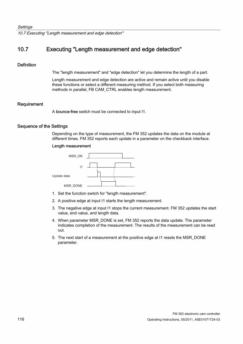
Settings 10.7 Executing "Length measurement and edge detection"
FM 352 electronic cam controller 116 Operating Instructions, 05/2011, A5E01071724-03
10.7 Executing "Length measurement and edge detection"
Definition The "length measurement" and "edge detection" let you determine the length of a part.
Length measurement and edge detection are active and remain active until you disable these functions or select a different measuring method. If you select both measuring methods in parallel, FB CAM_CTRL enables length measurement.
Requirement A bounce-free switch must be connected to input I1.
Sequence of the Settings Depending on the type of measurement, the FM 352 updates the data on the module at different times. FM 352 reports each update in a parameter on the checkback interface.
Length measurement
1. Set the function switch for "length measurement".
2. A positive edge at input I1 starts the length measurement.
3. The negative edge at input I1 stops the current measurement. FM 352 updates the start value, end value, and length data.
4. When parameter MSR_DONE is set, FM 352 reports the data update. The parameter indicates completion of the measurement. The results of the measurement can be read out.
5. The next start of a measurement at the positive edge at I1 resets the MSR_DONE parameter.
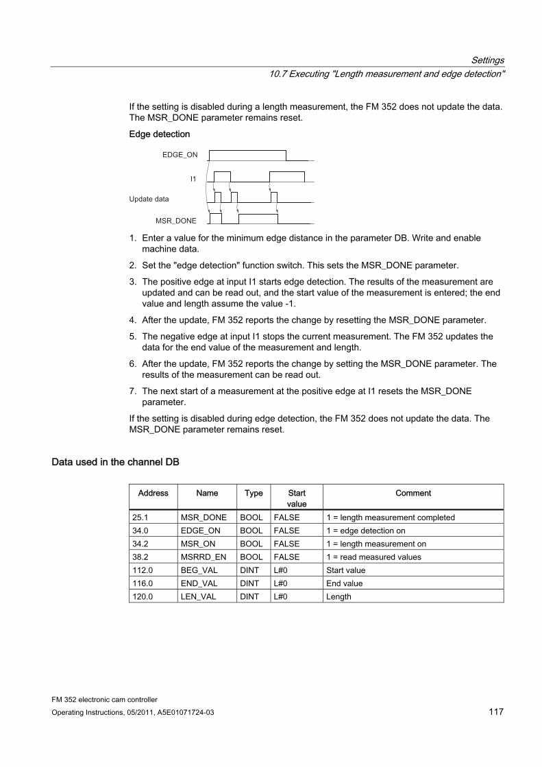
Settings 10.7 Executing "Length measurement and edge detection"
FM 352 electronic cam controller Operating Instructions, 05/2011, A5E01071724-03 117
If the setting is disabled during a length measurement, the FM 352 does not update the data. The MSR_DONE parameter remains reset.
Edge detection
1. Enter a value for the minimum edge distance in the parameter DB. Write and enable
machine data.
2. Set the "edge detection" function switch. This sets the MSR_DONE parameter.
3. The positive edge at input I1 starts edge detection. The results of the measurement are updated and can be read out, and the start value of the measurement is entered; the end value and length assume the value -1.
4. After the update, FM 352 reports the change by resetting the MSR_DONE parameter.
5. The negative edge at input I1 stops the current measurement. The FM 352 updates the data for the end value of the measurement and length.
6. After the update, FM 352 reports the change by setting the MSR_DONE parameter. The results of the measurement can be read out.
7. The next start of a measurement at the positive edge at I1 resets the MSR_DONE parameter.
If the setting is disabled during edge detection, the FM 352 does not update the data. The MSR_DONE parameter remains reset.
Data used in the channel DB
Address Name Type Start value
Comment
25.1 MSR_DONE BOOL FALSE 1 = length measurement completed 34.0 EDGE_ON BOOL FALSE 1 = edge detection on 34.2 MSR_ON BOOL FALSE 1 = length measurement on 38.2 MSRRD_EN BOOL FALSE 1 = read measured values 112.0 BEG_VAL DINT L#0 Start value 116.0 END_VAL DINT L#0 End value 120.0 LEN_VAL DINT L#0 Length
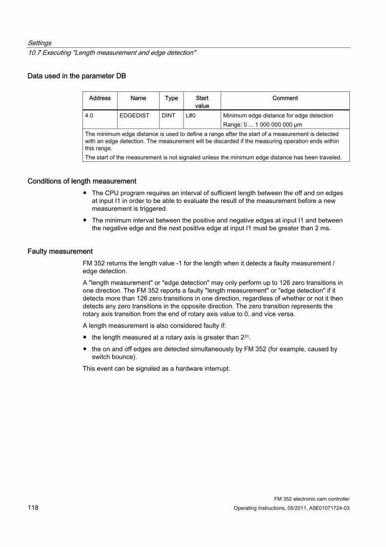
Settings 10.7 Executing "Length measurement and edge detection"
FM 352 electronic cam controller 118 Operating Instructions, 05/2011, A5E01071724-03
Data used in the parameter DB
Address Name Type Start value
Comment
4.0 EDGEDIST DINT L#0 Minimum edge distance for edge detection Range: 0 ... 1 000 000 000 µm
The minimum edge distance is used to define a range after the start of a measurement is detected with an edge detection. The measurement will be discarded if the measuring operation ends within this range. The start of the measurement is not signaled unless the minimum edge distance has been traveled.
Conditions of length measurement ● The CPU program requires an interval of sufficient length between the off and on edges
at input I1 in order to be able to evaluate the result of the measurement before a new measurement is triggered.
● The minimum interval between the positive and negative edges at input I1 and between the negative edge and the next positive edge at input I1 must be greater than 2 ms.
Faulty measurement FM 352 returns the length value -1 for the length when it detects a faulty measurement / edge detection.
A "length measurement" or "edge detection" may only perform up to 126 zero transitions in one direction. The FM 352 reports a faulty "length measurement" or "edge detection" if it detects more than 126 zero transitions in one direction, regardless of whether or not it then detects any zero transitions in the opposite direction. The zero transition represents the rotary axis transition from the end of rotary axis value to 0, and vice versa.
A length measurement is also considered faulty if:
● the length measured at a rotary axis is greater than 231.
● the on and off edges are detected simultaneously by FM 352 (for example, caused by switch bounce).
This event can be signaled as a hardware interrupt.

Settings 10.7 Executing "Length measurement and edge detection"
FM 352 electronic cam controller Operating Instructions, 05/2011, A5E01071724-03 119
Shift of the coordinate system during a length measurement Conditions under which a shift of the coordinate system will influence the measured length:
● You are using an incremental encoder or an initiator or are operating the FM 352 in simulation mode.
● You are executing a "set reference point" or "retrigger reference point" function while a length measurement is active.
Example To utilize the above mentioned influences on the measured length:
Your system always develops slip when you perform a length measurement.
The retrigger reference point function can be used to correct this slip in order to output correct length measurement values.
Settings 10.8 Retrigger reference point
FM 352 electronic cam controller 120 Operating Instructions, 05/2011, A5E01071724-03
10.8 Retrigger reference point
Definition The "Retrigger reference point" setting can be used to synchronize the axis as a reaction to a recurring external event.
The setting remains active until you deactivate it.
Requirements ● You are using an incremental encoder or an initiator.
● The external event may represent the zero mark signal of an incremental encoder or reference point switch at input I2.
Programming steps 1. Set the value for the reference point coordinate at the parameter DB.
2. Set the type of "retrigger reference point" at the parameter DB.
Options:
– Only the zero mark of the encoder is evaluated (RETR_TYPE = 7).
– Only the reference point switch is evaluated (RETR_TYPE = 6).
– Evaluation of the zero mark signal
in positive direction: evaluation of the first positive edge of the zero mark after passing the reference point switch in positive direction (RETR_TYPE = 0).
in negative direction: evaluation of the first negative edge of the zero mark signal after passing the reference point switch in negative direction (RETR_TYPE = 1).
3. Write and enable machine data.
4. Set the function switch in the channel DB.
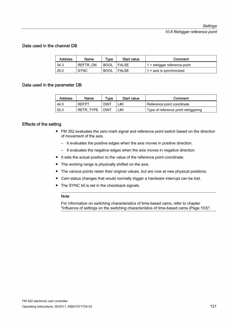
Settings 10.8 Retrigger reference point
FM 352 electronic cam controller Operating Instructions, 05/2011, A5E01071724-03 121
Data used in the channel DB
Address Name Type Start value Comment 34.3 REFTR_ON BOOL FALSE 1 = retrigger reference point 25.0 SYNC BOOL FALSE 1 = axis is synchronized
Data used in the parameter DB
Address Name Type Start value Comment 44.0 REFPT DINT L#0 Reference point coordinate 52.0 RETR_TYPE DINT L#0 Type of reference point retriggering
Effects of the setting ● FM 352 evaluates the zero mark signal and reference point switch based on the direction
of movement of the axis.
– It evaluates the positive edges when the axis moves in positive direction.
– It evaluates the negative edges when the axis moves in negative direction.
● It sets the actual position to the value of the reference point coordinate.
● The working range is physically shifted on the axis.
● The various points retain their original values, but are now at new physical positions.
● Cam status changes that would normally trigger a hardware interrupt can be lost.
● The SYNC bit is set in the checkback signals.
Note
For information on switching characteristics of time-based cams, refer to chapter "Influence of settings on the switching characteristics of time-based cams (Page 103)".
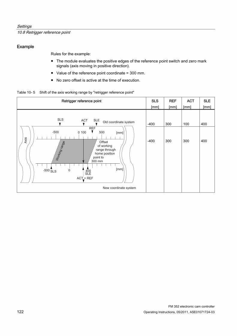
Settings 10.8 Retrigger reference point
FM 352 electronic cam controller 122 Operating Instructions, 05/2011, A5E01071724-03
Example Rules for the example:
● The module evaluates the positive edges of the reference point switch and zero mark signals (axis moving in positive direction).
● Value of the reference point coordinate = 300 mm.
● No zero offset is active at the time of execution.
Table 10- 5 Shift of the axis working range by "retrigger reference point"
Retrigger reference point SLS [mm]
REF [mm]
ACT [mm]
SLE [mm]
-400
300
100
400
-400
300
300
400
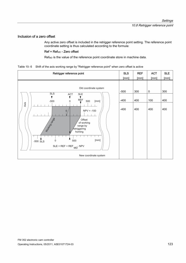
Settings 10.8 Retrigger reference point
FM 352 electronic cam controller Operating Instructions, 05/2011, A5E01071724-03 123
Inclusion of a zero offset Any active zero offset is included in the retrigger reference point setting. The reference point coordinate setting is thus calculated according to the formula:
Ref = RefMD - Zero offset
RefMD is the value of the reference point coordinate store in machine data.
Table 10- 6 Shift of the axis working range by "Retrigger reference point" when zero offset is active
Retrigger reference point SLS [mm]
REF [mm]
ACT [mm]
SLE [mm]
-500
300
0
300
-400
400
100
400
-400
400
400
400
Settings 10.9 Disabling software limit switches
FM 352 electronic cam controller 124 Operating Instructions, 05/2011, A5E01071724-03
10.9 Disabling software limit switches
Definition Use the "Disable software limit switches" function to disable monitoring of the software limit switches at a linear axis.
The setting remains active until you deactivate it. This re-enables the originally assigned software limit switches.
Programming steps Set the function switch in the channel DB.
Data used in the channel DB
Address Name Type Start value Comment 34.4 SSW_OFF BOOL FALSE 1 = software limit switch disabled
Data used in the parameter DB
Address Name Type Start value Comment 64.0 SSW_STRT DINT L#-1000000000 Software limit switch start 68.0 SSW_END DINT L#1000000000 Software limit switch end
Settings 10.9 Disabling software limit switches
FM 352 electronic cam controller Operating Instructions, 05/2011, A5E01071724-03 125
Effects of the setting ● simulation
– Simulation mode stops when the axis passes a software limit switch.
– You can resume simulation mode by enabling software limit switch monitoring. The axis moves in the defined direction.
● Zero offset when monitoring is disabled
With a zero offset setting, and software limit switches operating within traversing range limits, the actual value may still be out of the permissible number range.
● Cams located outside the assigned software limit switches can be switched.
CAUTION
Risk of material damage!
When taking safety measures such as reducing the traversing range by setting software limit switches, you risk damage to your equipment when these switches are disabled.
In the planning and engineering phases for your plant, you should be certain that the drive can travel in the entire physical traversing range.

Settings 10.10 Simulating
FM 352 electronic cam controller 126 Operating Instructions, 05/2011, A5E01071724-03
10.10 Simulating
Definition The "Simulation" setting allows you to activate the cam controller with open encoder connections.
Programming steps 1. Set the simulation velocity at the parameter DB.
2. Write and enable machine data.
3. Set either a positive or negative simulation direction at the channel DB.
4. Set the function switch in the channel DB.
Data used in the channel DB
Address Name Type Start value Comment 15.2 DIR_M BOOL FALSE 1 = simulation in negative direction 15.3 DIR_P BOOL FALSE 1 = simulation in positive direction 34.1 SIM_ON BOOL FALSE 1 = simulation on
Data used in the parameter DB
Address Name Type Start value Comment 84.0 SIM_SPD DINT L#0 Simulation velocity
Effects when simulation mode is activated ● Encoder signals will be ignored.
● The encoder input monitoring functions are disabled.
● All encoder errors reported will be reset.
● FM 352 simulates axis motion at a constant simulation velocity.
● Cam processing is disabled while simulation mode is active. However, you can then enable these operations again. Synchronism will be retained in this case.
● Starting at the current actual value, the actual position value changes dynamically based on the simulation velocity and direction.
Settings 10.10 Simulating
FM 352 electronic cam controller Operating Instructions, 05/2011, A5E01071724-03 127
Effects when simulation mode is deactivated ● Cam processing will be disabled.
● The synchronization of an incremental encoder or initiator will be cleared. The actual value will be reset to the value of the reference point coordinate.
● The module reports the actual position value which corresponds with the absolute encoder value. The module then evaluates the encoder signals as defined at the machine parameters.
Limit values The min./max. simulation velocity depends on the resolution (see chapter "Machine data of the axis (Page 75)").
Velocity The module may operate with differences between the online velocity and offline settings (see chapter "Machine data of the axis (Page 75)").
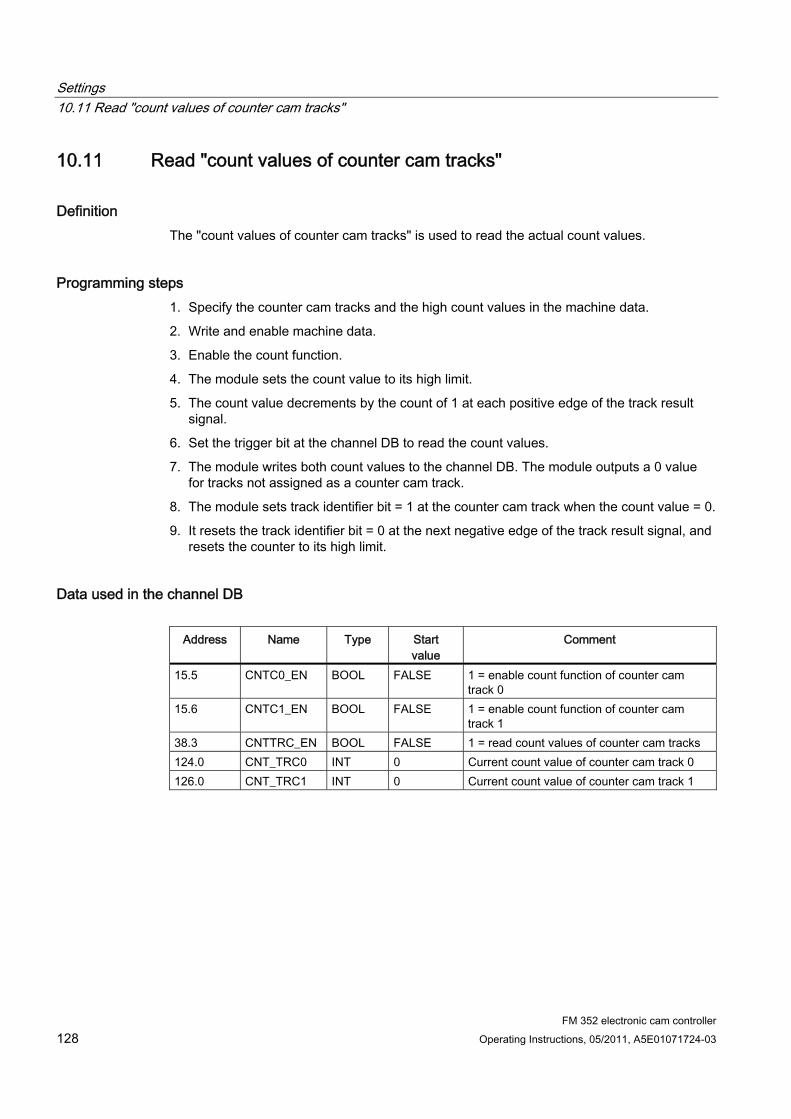
Settings 10.11 Read "count values of counter cam tracks"
FM 352 electronic cam controller 128 Operating Instructions, 05/2011, A5E01071724-03
10.11 Read "count values of counter cam tracks"
Definition The "count values of counter cam tracks" is used to read the actual count values.
Programming steps 1. Specify the counter cam tracks and the high count values in the machine data.
2. Write and enable machine data.
3. Enable the count function.
4. The module sets the count value to its high limit.
5. The count value decrements by the count of 1 at each positive edge of the track result signal.
6. Set the trigger bit at the channel DB to read the count values.
7. The module writes both count values to the channel DB. The module outputs a 0 value for tracks not assigned as a counter cam track.
8. The module sets track identifier bit = 1 at the counter cam track when the count value = 0.
9. It resets the track identifier bit = 0 at the next negative edge of the track result signal, and resets the counter to its high limit.
Data used in the channel DB
Address Name Type Start value
Comment
15.5 CNTC0_EN BOOL FALSE 1 = enable count function of counter cam track 0
15.6 CNTC1_EN BOOL FALSE 1 = enable count function of counter cam track 1
38.3 CNTTRC_EN BOOL FALSE 1 = read count values of counter cam tracks 124.0 CNT_TRC0 INT 0 Current count value of counter cam track 0 126.0 CNT_TRC1 INT 0 Current count value of counter cam track 1
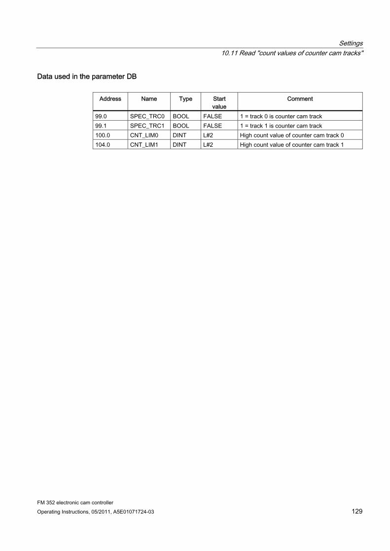
Settings 10.11 Read "count values of counter cam tracks"
FM 352 electronic cam controller Operating Instructions, 05/2011, A5E01071724-03 129
Data used in the parameter DB
Address Name Type Start value
Comment
99.0 SPEC_TRC0 BOOL FALSE 1 = track 0 is counter cam track 99.1 SPEC_TRC1 BOOL FALSE 1 = track 1 is counter cam track 100.0 CNT_LIM0 DINT L#2 High count value of counter cam track 0 104.0 CNT_LIM1 DINT L#2 High count value of counter cam track 1
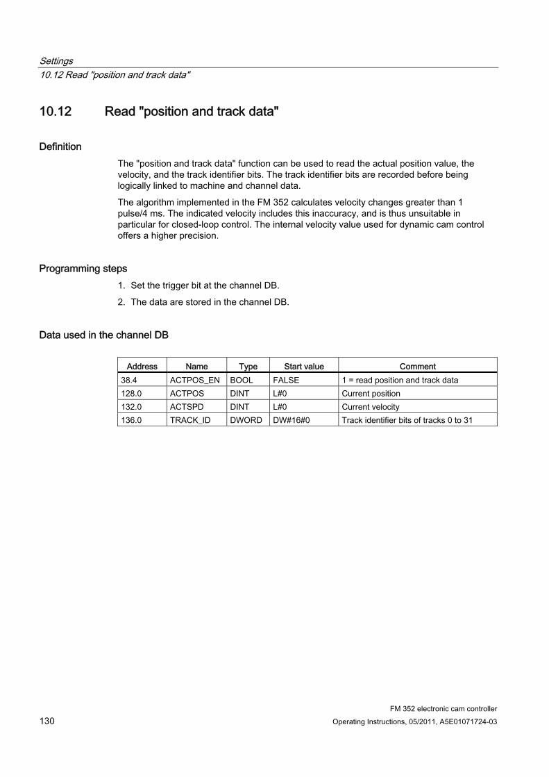
Settings 10.12 Read "position and track data"
FM 352 electronic cam controller 130 Operating Instructions, 05/2011, A5E01071724-03
10.12 Read "position and track data"
Definition The "position and track data" function can be used to read the actual position value, the velocity, and the track identifier bits. The track identifier bits are recorded before being logically linked to machine and channel data.
The algorithm implemented in the FM 352 calculates velocity changes greater than 1 pulse/4 ms. The indicated velocity includes this inaccuracy, and is thus unsuitable in particular for closed-loop control. The internal velocity value used for dynamic cam control offers a higher precision.
Programming steps 1. Set the trigger bit at the channel DB.
2. The data are stored in the channel DB.
Data used in the channel DB
Address Name Type Start value Comment 38.4 ACTPOS_EN BOOL FALSE 1 = read position and track data 128.0 ACTPOS DINT L#0 Current position 132.0 ACTSPD DINT L#0 Current velocity 136.0 TRACK_ID DWORD DW#16#0 Track identifier bits of tracks 0 to 31
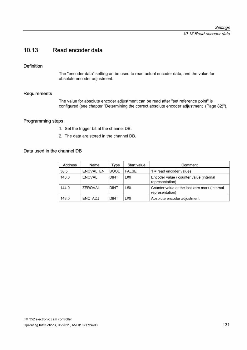
Settings 10.13 Read encoder data
FM 352 electronic cam controller Operating Instructions, 05/2011, A5E01071724-03 131
10.13 Read encoder data
Definition The "encoder data" setting an be used to read actual encoder data, and the value for absolute encoder adjustment.
Requirements The value for absolute encoder adjustment can be read after "set reference point" is configured (see chapter "Determining the correct absolute encoder adjustment (Page 82)").
Programming steps 1. Set the trigger bit at the channel DB.
2. The data are stored in the channel DB.
Data used in the channel DB
Address Name Type Start value Comment 38.5 ENCVAL_EN BOOL FALSE 1 = read encoder values 140.0 ENCVAL DINT L#0 Encoder value / counter value (internal
representation) 144.0 ZEROVAL DINT L#0 Counter value at the last zero mark (internal
representation) 148.0 ENC_ADJ DINT L#0 Absolute encoder adjustment

Settings 10.14 Read cam and track data
FM 352 electronic cam controller 132 Operating Instructions, 05/2011, A5E01071724-03
10.14 Read cam and track data
Definition The "cam and track data" setting can be used to read the actual cam / track identifier bits and the position. The track identifier bits are recorded before being logically linked to machine and channel data.
Programming steps 1. Enter type ID = 1 at the FM_TYPE parameter of the channel DB. This allows you to read
24 bytes of cam and track data.
If you enter type ID = 0, only the cam identifier bits (16 bytes) will be read.
2. The data are stored in the channel DB.
Data used in the channel DB
Address Name Type Start value
Comment
12.0 FM_TYPE BOOL FALSE 0 = FM 352 up to V4.0 1 = FM 352 V5.0 or higher
38.6 CAMOUT_EN BOOL FALSE 1 = read cam and track data 152.0 CAM_00_31 DWORD DW#16#0 Cam identifier bits for cams 0 to 31 156.0 CAM_32_63 DWORD DW#16#0 Cam identifier bits for cams 32 to 63 160.0 CAM_64_95 DWORD DW#16#0 Cam identifier bits for cams 64 to 95 164.0 CAM_96_127 DWORD DW#16#0 Cam identifier bits for cams 96 to 127 168.0 TRACK_ID1 DWORD DW#16#0 Track identifier bits of tracks 0 to 31 172.0 ACTPOS1 DINT L#0 Current position
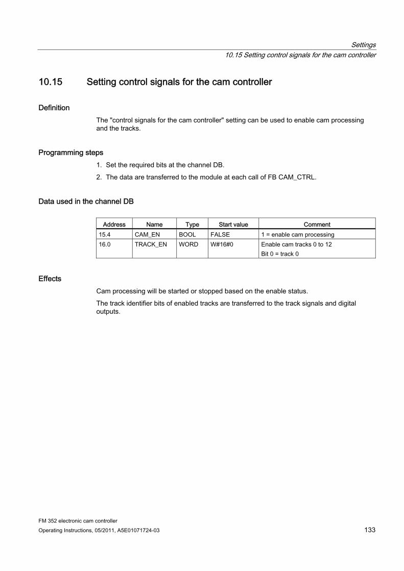
Settings 10.15 Setting control signals for the cam controller
FM 352 electronic cam controller Operating Instructions, 05/2011, A5E01071724-03 133
10.15 Setting control signals for the cam controller
Definition The "control signals for the cam controller" setting can be used to enable cam processing and the tracks.
Programming steps 1. Set the required bits at the channel DB.
2. The data are transferred to the module at each call of FB CAM_CTRL.
Data used in the channel DB
Address Name Type Start value Comment 15.4 CAM_EN BOOL FALSE 1 = enable cam processing 16.0 TRACK_EN WORD W#16#0 Enable cam tracks 0 to 12
Bit 0 = track 0
Effects Cam processing will be started or stopped based on the enable status.
The track identifier bits of enabled tracks are transferred to the track signals and digital outputs.

Settings 10.16 Querying checkback signals for the cam controller
FM 352 electronic cam controller 134 Operating Instructions, 05/2011, A5E01071724-03
10.16 Querying checkback signals for the cam controller
Definition The "checkback signals for the cam controller" setting informs you about the current state of the cam control and track signals. Consistency between the reported position and track signals is not guaranteed.
Programming steps The data are stored in the channel DB at each call of FB CAM_CTRL.
Data used in the channel DB
Address Name Type Start value Comment 23.4 CAM_ACT BOOL FALSE 1 = cam processing busy 26.0 ACT_POS DINT L#0 Current axis position 30.0 TRACK_OUT DWORD DW#16#0 Current track signals of tracks 0 to 31
Bit 0 = track 0
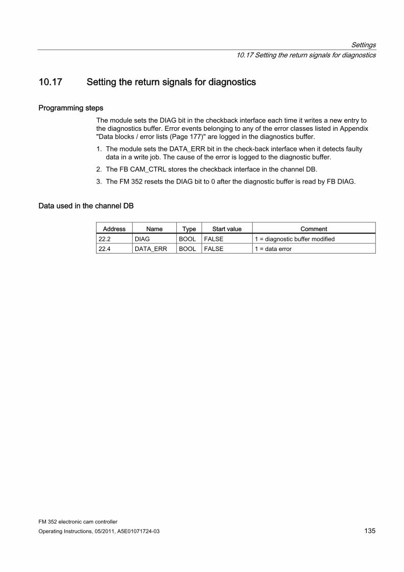
Settings 10.17 Setting the return signals for diagnostics
FM 352 electronic cam controller Operating Instructions, 05/2011, A5E01071724-03 135
10.17 Setting the return signals for diagnostics
Programming steps The module sets the DIAG bit in the checkback interface each time it writes a new entry to the diagnostics buffer. Error events belonging to any of the error classes listed in Appendix "Data blocks / error lists (Page 177)" are logged in the diagnostics buffer.
1. The module sets the DATA_ERR bit in the check-back interface when it detects faulty data in a write job. The cause of the error is logged to the diagnostic buffer.
2. The FB CAM_CTRL stores the checkback interface in the channel DB.
3. The FM 352 resets the DIAG bit to 0 after the diagnostic buffer is read by FB DIAG.
Data used in the channel DB
Address Name Type Start value Comment 22.2 DIAG BOOL FALSE 1 = diagnostic buffer modified 22.4 DATA_ERR BOOL FALSE 1 = data error

Settings 10.17 Setting the return signals for diagnostics
FM 352 electronic cam controller 136 Operating Instructions, 05/2011, A5E01071724-03
FM 352 electronic cam controller Operating Instructions, 05/2011, A5E01071724-03 137
Encoders 1111.1 Incremental encoders
Connectable incremental encoders The module supports incremental encoders outputting two pulses with 90° phase shift, and with or without zero mark signal:
● Encoders with asymmetrical 24 V output signals
– Limit frequency = 50 kHz
– Cable length max. 100 m
● Encoders with symmetrical output signals and 5 V differential interface conforming to RS422
– Limit frequency = 1 MHz
– with 5 V supply voltage: Cable length max. 32 m
– with 24 V supply voltage: Cable length max. 100 m
Note
If the encoder (5 V) does not output a zero mark signal and wire-break monitoring is disabled, you must interconnect the zero mark signal inputs N and /N externally so that the inputs will exhibit different signal levels (for example, N to 5 V, /N to ground).
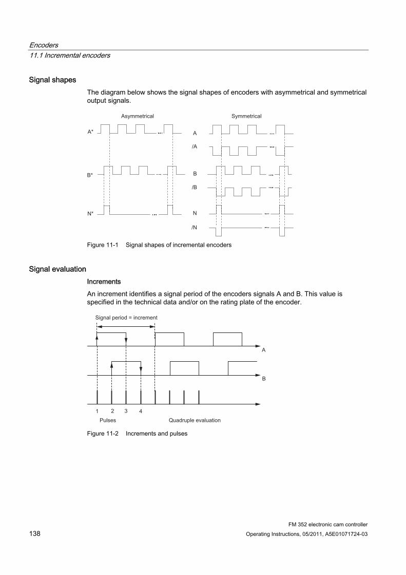
Encoders 11.1 Incremental encoders
FM 352 electronic cam controller 138 Operating Instructions, 05/2011, A5E01071724-03
Signal shapes The diagram below shows the signal shapes of encoders with asymmetrical and symmetrical output signals.
Figure 11-1 Signal shapes of incremental encoders
Signal evaluation Increments
An increment identifies a signal period of the encoders signals A and B. This value is specified in the technical data and/or on the rating plate of the encoder.
Figure 11-2 Increments and pulses
Encoders 11.1 Incremental encoders
FM 352 electronic cam controller Operating Instructions, 05/2011, A5E01071724-03 139
Pulses The FM 352 evaluates all 4 edges of the A and B signals (see diagram) in each increment (quadruple evaluation).
1 increment (encoder default) = 4 pulses (FM evaluation)
Reaction times The FM 352 has the following reaction times for connected incremental encoders:
Minimum reaction time = cam cycle time + switching time of the connected switching elements
Maximum reaction time = 2 x cam cycle time + switching time of the connected switching elements
Example Example of the min./max. reaction time with 16 cams available:
● Cam cycle time: approx. 20 µs
● Switching time of the hardware: approx. 150 µs
Minimum reaction time = 20 µs + 150 µs = 170 µs
Maximum reaction time = 2 x 20 µs + 150 µs = 190 µs
Note
You can compensate the reaction time by assigning the cam parameters accordingly or using dynamic adjustment.
Flat gain The flat gain is equivalent to the difference between the min./max. reaction time. For incremental encoders this is:
Flat gain = cam cycle time
Note
If the switching time of the FM 352 hardware and of the connected switching elements can be disregarded, reliable cam activation is always ensured if the cam is longer than the distance covered within the cam cycle time.

Encoders 11.2 Proximity switches
FM 352 electronic cam controller 140 Operating Instructions, 05/2011, A5E01071724-03
11.2 Proximity switches
Definition Initiators are simple switches which output pulse-shaped signals, and do not return a directional signal. You define the direction based on the machine data for selecting the initiator.
CAUTION Risk of material damage!
Incorrect direction settings can cause serious errors in the system (for example, faulty control of a unit of equipment).
Check the direction settings in the commissioning phase, and whenever you replace an initiator.
Supported initiators The FM 352 supports the following initiators:
● Initiators with 24 V signal level (proximity switches) Limit frequency = 50 kHz
● Cable length max. 100 m
Signal evaluation With an initiator, the positive edges of signal A* are counted.
Encoders 11.3 Absolute encoder
FM 352 electronic cam controller Operating Instructions, 05/2011, A5E01071724-03 141
11.3 Absolute encoder
Single-turn and multiturn encoders Absolute encoders are divided into the categories:
● Single-turn encoder
The total range of single-turn encoders is scale to one revolution.
● Multiturn encoder
The total range of multiturn encoders is scaled to several revolutions.
Supported absolute encoders Absolute encoders with serial interface. Position data are transferred synchronously using the SSI protocol (SynchronousSerialInterface). FM 352 only supports GRAY code. Due to the arrangement of the data bits in the transferred frames, the data formats "fir tree", "half fir tree" and "right-justified" are used.
Encoder type Frame length / type Single-turn encoder Single-turn encoder Single-turn encoder Multiturn encoder Multiturn encoder Listen in Listen in
13-bit half fir tree 13-bit right-justified 25-bit right-justified 25-bit fir tree 25-bit right-justified Fir tree Right-justified
Special setting: Multiturn encoder in single-turn mode
25-bit half fir tree
Data transfer The data rate for data transmission depends on the cable length (see chapter "Technical data (Page 166)").
Pulse evaluation with absolute encoders 1 increment (encoder default) = 1 pulse (FM evaluation)
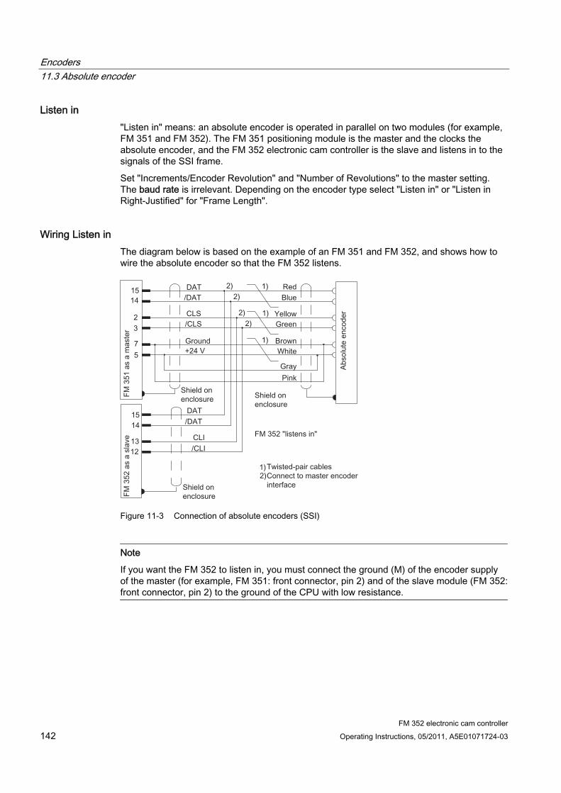
Encoders 11.3 Absolute encoder
FM 352 electronic cam controller 142 Operating Instructions, 05/2011, A5E01071724-03
Listen in "Listen in" means: an absolute encoder is operated in parallel on two modules (for example, FM 351 and FM 352). The FM 351 positioning module is the master and the clocks the absolute encoder, and the FM 352 electronic cam controller is the slave and listens in to the signals of the SSI frame.
Set "Increments/Encoder Revolution" and "Number of Revolutions" to the master setting. The baud rate is irrelevant. Depending on the encoder type select "Listen in" or "Listen in Right-Justified" for "Frame Length".
Wiring Listen in The diagram below is based on the example of an FM 351 and FM 352, and shows how to wire the absolute encoder so that the FM 352 listens.
Figure 11-3 Connection of absolute encoders (SSI)
Note
If you want the FM 352 to listen in, you must connect the ground (M) of the encoder supply of the master (for example, FM 351: front connector, pin 2) and of the slave module (FM 352: front connector, pin 2) to the ground of the CPU with low resistance.
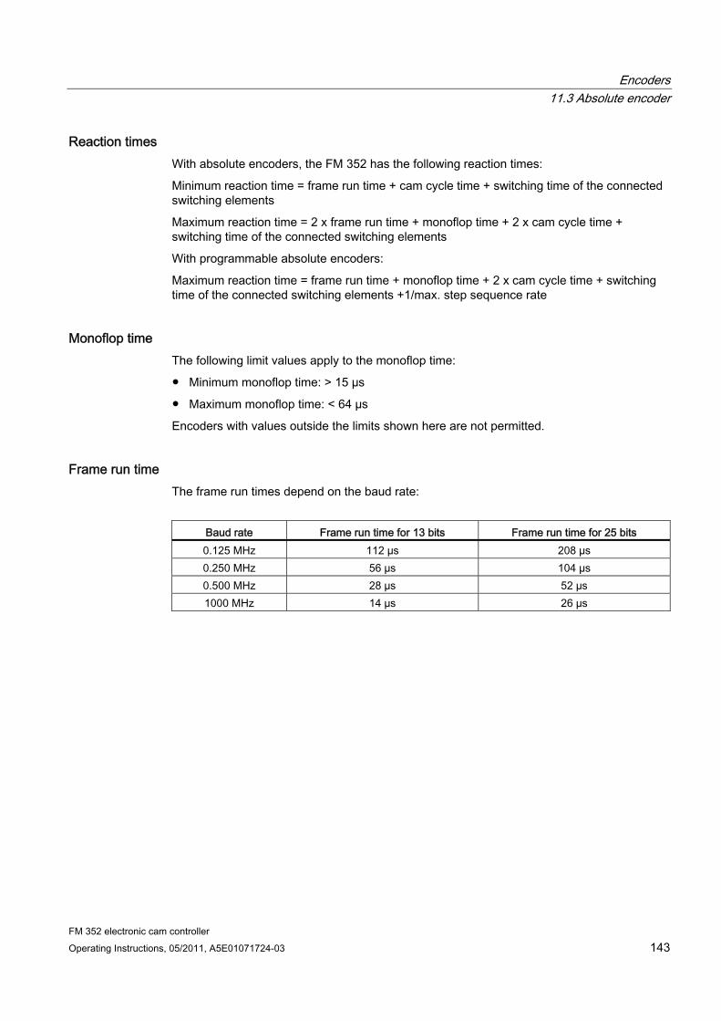
Encoders 11.3 Absolute encoder
FM 352 electronic cam controller Operating Instructions, 05/2011, A5E01071724-03 143
Reaction times With absolute encoders, the FM 352 has the following reaction times:
Minimum reaction time = frame run time + cam cycle time + switching time of the connected switching elements
Maximum reaction time = 2 x frame run time + monoflop time + 2 x cam cycle time + switching time of the connected switching elements
With programmable absolute encoders:
Maximum reaction time = frame run time + monoflop time + 2 x cam cycle time + switching time of the connected switching elements +1/max. step sequence rate
Monoflop time The following limit values apply to the monoflop time:
● Minimum monoflop time: > 15 µs
● Maximum monoflop time: < 64 µs
Encoders with values outside the limits shown here are not permitted.
Frame run time The frame run times depend on the baud rate:
Baud rate Frame run time for 13 bits Frame run time for 25 bits 0.125 MHz 112 µs 208 µs 0.250 MHz 56 µs 104 µs 0.500 MHz 28 µs 52 µs 1000 MHz 14 µs 26 µs
Encoders 11.3 Absolute encoder
FM 352 electronic cam controller 144 Operating Instructions, 05/2011, A5E01071724-03
Example of Reaction Times The following example shows how to calculate the minimum and maximum reaction time. In the example a programmable encoder is not used.
● Cam cycle time: approx. 20 µs for max. 16 cams
● Switching time of the hardware: approx. 150 µs
● Frame run time: 26 µs at a baud rate of 1 MHz (25-bit frame)
● Monoflop time: 20 µs (depends on the encoder: typical 20 µs to 40 µs
Maximum reaction time = 26 µs + 20 µs + 150 µs = 196 µs
Maximum reaction time = 2 x 26 µs + 20 µs + 2 x 20 µs + 150 µs = 262 µs
Note
You can compensate the reaction time by assigning the cam parameters accordingly or using dynamic adjustment.
Flat gain The flat gain is equivalent to the difference between the min./max. reaction time.
With an absolute encoder it is as follows:
Flat gain = cam cycle time + frame run time + monoflop time
With a programmable absolute encoder, it is as follows:
Flat gain = cam cycle time + frame run time + monoflop time + 1/max. step sequence frequency
Note
If the switching time of the FM 352 hardware and of the connected switching elements can be disregarded, reliable cam activation is always ensured if the cam is longer than the distance covered within the cam cycle time.
FM 352 electronic cam controller Operating Instructions, 05/2011, A5E01071724-03 145
Diagnostics 1212.1 Possibilities for error evaluation
Overview ● With the programming device/PC, you can read out the diagnostic buffer with the
parameter assignment user interface using Test > Error Evaluation.
– You will see the error class and error number along with plain text.
● You can evaluate errors in your program. The following options are available:
– The RETVAL return values in the instance DBs of the integrated FBs as a group display for errors that occurred during execution of the FBs.
– The error bits of the jobs as a group display for errors that occurred while executing a job.
– The error bit DATA_ERR as a group display for an error detected by the FM 352 during a write job.
– The error identifier in JOB_ERR, for the cause of an error during communication between the FB and FM 352.
– FB CAM_DIAG for reading out the diagnostic buffer of the FM 352. Here, you can find out the causes of errors in jobs and asynchronous events (operating errors, diagnostic errors).
– Diagnostic interrupts for fast reaction to events.
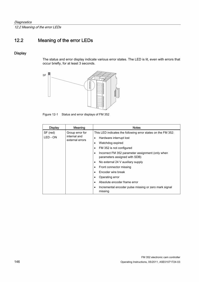
Diagnostics 12.2 Meaning of the error LEDs
FM 352 electronic cam controller 146 Operating Instructions, 05/2011, A5E01071724-03
12.2 Meaning of the error LEDs
Display The status and error display indicate various error states. The LED is lit, even with errors that occur briefly, for at least 3 seconds.
Figure 12-1 Status and error displays of FM 352
Display Meaning Notes
SF (red) LED - ON
Group error for internal and external errors
This LED indicates the following error states on the FM 352: Hardware interrupt lost Watchdog expired FM 352 is not configured Incorrect FM 352 parameter assignment (only when
parameters assigned with SDB) No external 24 V auxiliary supply Front connector missing Encoder wire break Operating error Absolute encoder frame error Incremental encoder pulse missing or zero mark signal
missing
Diagnostics 12.3 Diagnostic interrupts
FM 352 electronic cam controller Operating Instructions, 05/2011, A5E01071724-03 147
12.3 Diagnostic interrupts
12.3.1 Enable diagnostic interrupts
Interrupt processing The FM 352 can trigger hardware and diagnostic interrupts. Process those interrupts in an interrupt OB. If an interrupt is triggered and the corresponding OB is not loaded, the CPU goes to STOP mode (refer to the Programming with STEP 7 Manual).
You enable the servicing of diagnostic interrupts as follows:
1. Select the module in HW Config
2. Select Edit > Object Properties > Basic Parameters to enable the diagnostic interrupt.
3. Save and compile the hardware configuration.
4. Download the hardware configuration to the CPU.
Overview of the Diagnostic Interrupts Events and errors triggering a diagnostic interrupt:
● Operating error
● Incorrect machine data (when parameters assigned with SDB)
● Incorrect cam data (when parameters assigned with SDB)
● Diagnostic errors
These errors are explained in detail in the appendix "Error classes (Page 190)".
Diagnostics 12.3 Diagnostic interrupts
FM 352 electronic cam controller 148 Operating Instructions, 05/2011, A5E01071724-03
12.3.2 Reaction of FM 352 to errors with diagnostics interrupt
Reactions ● Cam processing will be disabled.
● The synchronization will be cleared by the following diagnostic interrupts:
– Front connector missing, external power supply missing
– zero mark error detected, cable fault (5-V encoder signals)
– traversing range exceeded (indicated by a process/hardware error)
– Set actual value cannot be executed (indicated by a process error).
● With one exception, control signals are no longer processed.
Exception:
When the software limit switch is crossed, a direction reversal is still possible in simulation mode.
● Function switch and job processing continues.
FM 352 detects an error ("incoming") A diagnostic interrupt is an "incoming" event if at least one error is pending. If any errors are pending clearance, the queued errors are reported again as "incoming" events.
Sequence:
1. FM 352 detects one or several errors, and generates a diagnostic interrupt. The "SF" LED is lit. The error event is logged to the diagnostic buffer.
2. The CPU operating system calls OB82.
3. You can now evaluate the start information of OB82.
4. The OB82_MOD_ADDR parameter indicates which module triggered the interrupt.
5. Further information is available when the FB CAM_DIAG is called.
FM 352 detects the transition to the error-free state ("outgoing") A diagnostic interrupt is only registered "outgoing" if all errors on the module are cleared.
Sequence:
1. FM 352 detects that all errors have been cleared and triggers a diagnostic interrupt. The "SF" LED is no longer lit. The diagnostic buffer remains unchanged.
2. The CPU operating system calls OB82.
3. The OB82_MOD_ADDR parameter indicates which module triggered the interrupt.
4. Evaluate the OB82_MDL_DEFECT bit.
When this bit is "0", no errors are present on the module. You can close the evaluation session at this point.

Diagnostics 12.3 Diagnostic interrupts
FM 352 electronic cam controller Operating Instructions, 05/2011, A5E01071724-03 149
Diagnostic interrupt control by CPU states ● Diagnostic interrupts are blocked by the FM 352 when the CPU is in STOP mode.
● If none of the queued errors were cleared while the CPU was in STOP, the FM 352 reports all these errors as "incoming" event at the next CPU transition to RUN.
● If all existing errors were cleared while the CPU was in STOP, FM 352 does not report its error-free state with a diagnostic interrupt at the next CPU transition to RUN.

Diagnostics 12.3 Diagnostic interrupts
FM 352 electronic cam controller 150 Operating Instructions, 05/2011, A5E01071724-03
FM 352 electronic cam controller Operating Instructions, 05/2011, A5E01071724-03 151
Examples 1313.1 Introduction
Example project folder The FM 352/FM 452 software package you installed contains example projects showing you several typical applications based on a number of selected functions.
The English example project for the FM 352 is in the following folder:
...\STEP7\EXAMPLES\zEn19_02
This folder contains several S7 programs of varying complexity and objectives.
Examples 13.2 Requirements
FM 352 electronic cam controller 152 Operating Instructions, 05/2011, A5E01071724-03
13.2 Requirements
Overview The following requirements must be met:
● You have installed and wired an S7 station, consisting of a power supply module, a CPU and an FM 352 module (version ≥V5). The characteristics of earlier module versions may deviate from the description.
● STEP 7 and the FM 352 configuration package are properly installed on your PG/PC. The handling instructions are based on STEP 7 V5.0. The procedure may differ for other versions.
● The PG is connected to the CPU.
You can operate an FM 352 using these example projects. All examples can also be executed on an FM 352 in a distributed configuration. To use the "MultiModules" example, you require 2 modules.

Examples 13.3 Preparing the examples
FM 352 electronic cam controller Operating Instructions, 05/2011, A5E01071724-03 153
13.3 Preparing the examples
Procedure In order to work through the examples online, you must prepare as follows:
1. Open the \STEP7\EXAMPLES\zEn19_02_FMx52___Prog example project in SIMATIC Manager, then copy it under a suitable name to your project folder.
2. Insert a station in this project according to your hardware configuration.
3. Complete the hardware configuration with HW Config and save the configuration.
4. Select an example program and copy its block container to your station.
5. Assign parameters for the FM 352 in HW Config using the instructions provided in the SIMATIC Function Modules FM 352 - First Steps in Commissioning, section FM 352 parameter assignment (http://support.automation.siemens.com/WW/view/en/1407842).
6. Enter the module address in the associated channel DB and, if necessary, also in the corresponding diagnostic DB in the "MOD_ADDR" parameter (refer to the section entitled Basics of Programming an FM 352 (Page 40)).
7. Download the hardware configuration to your CPU.
8. Download the blocks to your CPU.
9. To try out the next example, go to step 4.
13.4 Displaying the code of the examples
Display The samples are written in STL.
You can view them directly in the LAD/STL/FBD editor.
Select the view with "Symbolic representation", "Symbol selection" and "Comment." If your screen provides sufficient space, you can also open the "Symbol information" view.
Examples 13.5 Testing the example
FM 352 electronic cam controller 154 Operating Instructions, 05/2011, A5E01071724-03
13.5 Testing the example
Procedure After you have successfully completed all necessary entries, download the entire block folder to the CPU.
The example programs include variable tables (VATs) you can use to view and change data blocks online (i.e., in CPU RUN mode).
1. From the variable table, select the "Symbol" and "Symbol Comment" views.
2. Open a variable table.
3. Open the variable table with the configured CPU, and monitor the variables cyclically.
This updates the variables dynamically when the CPU is in RUN mode.
All the examples require that the machine data and cam data were entered and saved using the parameter assignment interface. This allows you to work through the examples sequentially.
13.6 Reusing an example project
Restrictions The code of the samples in neither optimized nor designed for all eventualities.
Error evaluation is not programmed in detail in the sample programs in order to avoid the programs becoming unwieldy.
Examples 13.7 Sample program 1 "Getting Started"
FM 352 electronic cam controller Operating Instructions, 05/2011, A5E01071724-03 155
13.7 Sample program 1 "Getting Started"
Objective In this example, you commission your cam controller after you have assigned its parameters in the parameter assignment interface according to the "Getting Started" manual.
The example extends the program shown in the "Integration in the User Program" chapter of the getting started by adding error evaluation.
Requirements ● You have assigned the cam controller parameters as described in the "Getting Started"
Manual.
Startup Enter the address of your module in channel DB at the MOD_ADDR address.
In the startup OB (OB 100), call FC CAM_INIT to reset all control and checkback signals as well as job management in the channel DB.
Cyclic operation 1. Open the variable table.
2. Go online to the configured CPU to monitor the variables.
3. Transfer the prepared control values.
The module changes to simulation mode. You can see how the actual value CAM.ACT_POS and track signals CAM.TRACK_OUT change dynamically.
4. Now change the simulation direction, specify different reference point coordinates, then disable simulation etc. by modifying and transferring the control values.
Error evaluation Generate a data error by entering a reference point coordinate greater than the end of rotary axis (for example, 10000000). The CPU goes into STOP. In an example, this is the simplest method of indicating an error. You can, of course, program a more sophisticated method.
Open the hardware configuration and double-click the FM 352. This opens the parameter assignment interface. Select Test > Error evaluation to view the cause of the error.
To clear the error:
1. Enter a valid control value.
2. Switch the CPU to STOP.
3. Switch the CPU to RUN mode.
4. Enable the control values. If you enable the control values before restarting the CPU, they are canceled by the initialization routine in OB100, and thus have no effect.
Examples 13.8 Sample Program 2 "Commissioning"
FM 352 electronic cam controller 156 Operating Instructions, 05/2011, A5E01071724-03
13.8 Sample Program 2 "Commissioning"
Objective In this sample, you commission a cam controller without using the programming interface. You control and monitor the system using the variable tables (VATs).
Requirements You have assigned the cam controller parameters as described in the "Getting Started" Manual.
The module address is entered in the MOD_ADDR block parameter in the channel and diagnostic DBs.
The included channel DB already contains the DB number (3) of the parameter DB in the PARADBNO parameter.
PARADB included in this example contains default machine and cam data.
Startup In the startup OB (OB100), call FC CAM_INIT to initialize the channel DB. Next, set the trigger bits for all jobs and control signals you require when the module has completed its startup.
Cyclic operation Open the variable tables VAT1 and VAT2, then go online to the configured CPU to monitor the variables.
At VAT1, you can view the changes in the actual position and the track signals. The module is in operation.
In VAT2, you can see the most important entries of the diagnostic buffer of the module. For information on error classes and numbers, refer to the appendix "Error classes (Page 190)".
Edit the machine and cam data at DB PARADB, download the DB to the CPU, and then enable the control values in VAT1. This writes the new data to the module, and enables these. Faulty data are indicated in VAT2. For information on machine and cam data, refer to the chapter "Machine and cam data (Page 67)".
Error evaluation Try to generate further errors:
● Define a reference point coordinate which is greater than the end of the rotary axis.
● Switch off the external power supply.
● Delete PARADB from the CPU (online), and then attempt to write machine data. The error evaluation is intentionally programmed here so that the CPU goes to STOP mode. If you update VAT1 once again, the error code for this error is indicated in CAM.JOB_ERR.
Examples 13.9 Sample program 3 "One Module"
FM 352 electronic cam controller Operating Instructions, 05/2011, A5E01071724-03 157
13.9 Sample program 3 "One Module"
Objective In this example, you control a cam controller in a user program. The user program commissions the module after a CPU restart. Next, it executes a step sequence that is triggered by certain events.
Using the variable tables, you define events, monitor the reactions of the module, and evaluate the diagnostic buffer.
In this slightly more complex example, you can get to know the following block possibilities:
● Issuing several jobs simultaneously
● Mixing write and read jobs
● Reading with a continuous job, without waiting for the end of the job
● Evaluation of the checkback signals of the block
● Evaluation of the checkback signals for an individual job
● Resetting of done bits and error bits for individual jobs or all jobs
● Central CAM_CTRL call at the end of the user program
● Central error evaluation by CAM_DIAG at the end of the user program
● Evaluation of the diagnostic buffer in conjunction with DATA_ERR
Requirements ● You have assigned the cam controller parameters as described in the "Getting Started"
Manual.
● The module address is entered in the MOD_ADDR block parameter in the channel and diagnostic DBs.
● The included channel DB already contains the DB number (3) of the parameter DB in the PARADBNO parameter.
● PARADB included in this example contains default machine and cam data.
Startup In the startup OB (OB 100), set the startup identifier (step 0) for the user program in the corresponding instance DB.
Examples 13.9 Sample program 3 "One Module"
FM 352 electronic cam controller 158 Operating Instructions, 05/2011, A5E01071724-03
Operation The CPU is in STOP.
1. Open variable table VAT1, then transfer the control values.
2. Restart the CPU (STOP > RUN). You can see how the actual position (CAM.ACT_POS), the cam data (CAM.CAM_00_31) and the track signals (CAM.TRACK_OUT) change. You should also observe the step number of the step sequence (PROGDB.STEPNO).
When cam 4 is set (130 degrees), cams 0 and 1 are reassigned to the values you specified in VAT 1. You can view the change in the VAT.
Next, the program waits for an external event.
3. Once again, transfer the prepared control values from the VAT (this time, PROGDB.SWITCH is evaluated). The previous values will be restored in the cam data.
The step sequence is completed after this cycle, the step number = -2, and simulation is stopped.
If you want to repeat the entire sequence again, restart the CPU (STOP > RUN). (This procedure is, of course, only acceptable in the sample program.)
If you have not activated the PROGDB.SWITCH switch before a CPU STOP, the cam parameters in the parameter DB will not be reset to their original values. In this case, once again download the parameter DB to the CPU.
Error evaluation Any processing error will stop the step sequence and disable simulation mode. Step number -1 will be entered.
Try to generate cam errors the central error evaluation will save to the PROGDB.CAM_ERR bit as group error.
● Set cam positions in VAT1 which are greater than the end of rotary axis.
● Define negative cam positions in VAT1.
User program (FB PROG) The user program accesses data in the module-specific data blocks using the <blockname>.<symbolic name> syntax. The user program can thus operate exactly one module.
With this type of programming, you can access DB data using symbolic names. Indirect addressing of several modules is part of sample program 5 "MultiModules".
The user program executes a step sequence as follows:
Step 0: Initialization of the cam controller. Sets the jobs and corresponding data to be executed at a restart of the module. The restart of the module may be triggered by a CPU restart, or by the return of a rack, for example.
Step 1: The program waits for the set jobs to be executed.
Step 2: The program continuously reads the cam identifier bits and waits until cam 4 is set.
Examples 13.9 Sample program 3 "One Module"
FM 352 electronic cam controller Operating Instructions, 05/2011, A5E01071724-03 159
Step 3: Cams 0 and 1 receive new parameters. To let you view the change, the cam data are read before and after the change and indicated at VAT1.
Step 4: The program waits for the set jobs to be executed.
Step 5: The program waits for the "external" event "switch on" (CAM.SWITCH = 1), which you can set via the VAT.
Step 6: The incoming event resets cams 0 and 1 to the value read in the initialization step.
Step 7: The program waits for the set jobs to be executed.
FB CAM_CTRL and FB CAM_DIAG are called at the end of the step sequence. The CAM_ERR output will be set if the diagnostics function has detected a message about incorrect cam data.
Examples 13.10 Sample program 4 "Interrupts"
FM 352 electronic cam controller 160 Operating Instructions, 05/2011, A5E01071724-03
13.10 Sample program 4 "Interrupts"
Objective This sample contains a user program with the same task as in sample program 3 "One Module". In this sample, you are shown how to evaluate a diagnostic interrupt for specific modules, and how to process this in the user program to produce a general module error.
Requirements ● You have assigned the cam controller parameters as described in the "Getting Started."
● The module address is entered in the MOD_ADDR block parameter in the channel and diagnostic DBs.
● In HW Config, enable the diagnostic interrupt for this module with Edit > Object Properties > Basic Parameters > Select Interrupt > Diagnostics. Compile the hardware configuration, and then download it to the CPU.
● The included channel DB already contains the DB number (3) of the parameter DB in the PARADBNO parameter.
● PARADB included in this example contains default machine and cam data.
Startup In the startup OB (OB100), the startup identifier (step 0) for the user program is set in the instance DB.
Operation As in sample program 3 "One Module".
Error evaluation As in sample program 3 "One Module".
Generate diagnostic interrupts by disconnecting the auxiliary power supply to the module, or by removing the front connector. The module error MOD_ERR and diagnostic error OB82_ERR will be set to 1, and the step number assumes a -1. The error identifiers will be canceled once you have cleared the error. Cam processing and simulation, however, remain disabled.
Examples 13.10 Sample program 4 "Interrupts"
FM 352 electronic cam controller Operating Instructions, 05/2011, A5E01071724-03 161
User program (FB PROG) The task is the same as in sample program 3 "One Module". However, the block was expanded by adding evaluation of the diagnostics event.
In this sample, no special measures have been taken for restarting after eliminating the error. We have left this up to you as part of the exercise.
Diagnostic interrupt (OB82) Depending on the address of the module that triggered the interrupt (OB82_MDL_ADDR), the error identifier in the corresponding instance DB of the user program is entered in the diagnostic interrupt.
Examples 13.11 Sample program 5 "MultiModules"
FM 352 electronic cam controller 162 Operating Instructions, 05/2011, A5E01071724-03
13.11 Sample program 5 "MultiModules"
Objective This sample contains the same user program as sample program 3 "One Module", but this time it is used to operate two modules with different cam parameters. The user program uses an own instance of CAM_CTRL and CAM_DIAG for each module, a multiple instance is not possible. The user program expects a module address as input parameter. The DB numbers for channel and diagnostic DBs associated with this address are stored as constants in the program and can be modified by you.
Requirements You have inserted two FM 352 modules and configured these in HW Config.
You have assigned parameters for both cam controllers as described in the "Getting Started" Manual.
The address of the relevant module has been entered in the block parameter MOD_ADDR in the channel and diagnostic DBs.
The included channel DBs already contain the DB number (3 or 13) of the corresponding parameter DB in the PARADBNO parameter.
The PARADB and PARADB2 parameter DBs of the sample project contain default machine and cam data for both modules.
A set of variable tables is also prepared for each module.
Startup In the startup OB (OB 100), set the startup identifier (step 0) for the user program at both instance DBs.
Operation The CPU is in STOP.
● Open VAT1 and VAT11, and transfer their control values.
● Start the CPU (STOP > RUN).
You can see how monitor the change of the actual positions, of cam data, and of the track signals of both modules.
Error evaluation As in sample program 4 "Interrupts", but separately for each of the two modules.
Examples 13.11 Sample program 5 "MultiModules"
FM 352 electronic cam controller Operating Instructions, 05/2011, A5E01071724-03 163
User program (FB PROG) The objective and sequence of the user program are as in sample program 4 "Interrupts" and sample program 3 "One Module".
The user program is designed for the operation of more than one module, since it accesses the module-specific data blocks: channel DB, diagnostic DB, and parameter DB. The DB number specified during call up is used in the user program to select the instance DB. With this type of programming, you cannot use symbolic names for the data in the data blocks because of the "Open global data block" instruction used in the user program.
Diagnostic interrupt (OB 82) Depending on the address of the module that triggered the interrupt (OB82_MDL_ADDR), the error identifier in the corresponding instance DB of the user program is entered in the diagnostic interrupt.

Examples 13.11 Sample program 5 "MultiModules"
FM 352 electronic cam controller 164 Operating Instructions, 05/2011, A5E01071724-03
FM 352 electronic cam controller Operating Instructions, 05/2011, A5E01071724-03 165
Technical data AA.1 General technical data
The following technical data are available in the Operating Instructions SIMATIC S7-300 CPU 31xC and CPU 31x: Installation (http://support.automation.siemens.com/WW/view/en/13008499).
● Standards and licenses
● Electromagnetic compatibility
● Transport and storage conditions
● Mechanical and climatic environmental conditions
● Specifications for insulation tests, protection class, degree of protection, and rated voltage
● Rated voltages
Observe installation guidelines SIMATIC products meet the requirements if you follow the installation instructions described in the manuals when installing and operating the equipment.
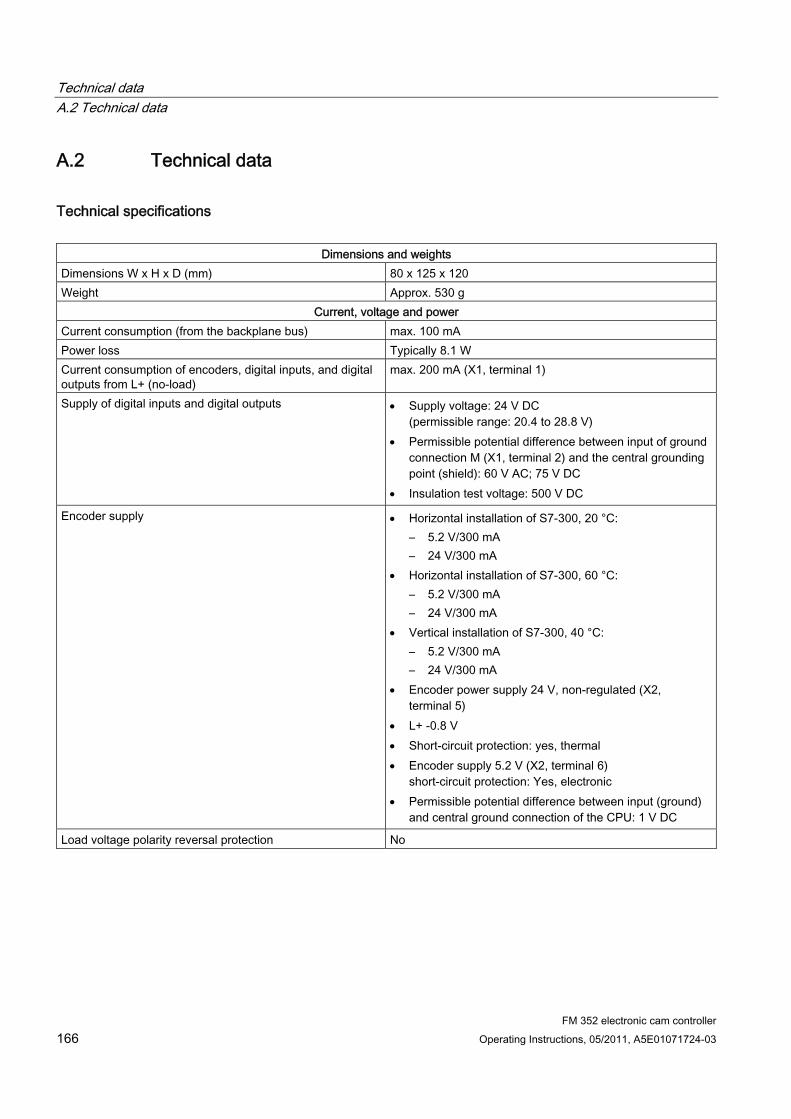
Technical data A.2 Technical data
FM 352 electronic cam controller 166 Operating Instructions, 05/2011, A5E01071724-03
A.2 Technical data
Technical specifications
Dimensions and weights Dimensions W x H x D (mm) 80 x 125 x 120 Weight Approx. 530 g
Current, voltage and power Current consumption (from the backplane bus) max. 100 mA Power loss Typically 8.1 W Current consumption of encoders, digital inputs, and digital outputs from L+ (no-load)
max. 200 mA (X1, terminal 1)
Supply of digital inputs and digital outputs Supply voltage: 24 V DC (permissible range: 20.4 to 28.8 V)
Permissible potential difference between input of ground connection M (X1, terminal 2) and the central grounding point (shield): 60 V AC; 75 V DC
Insulation test voltage: 500 V DC
Encoder supply Horizontal installation of S7-300, 20 °C: – 5.2 V/300 mA – 24 V/300 mA
Horizontal installation of S7-300, 60 °C: – 5.2 V/300 mA – 24 V/300 mA
Vertical installation of S7-300, 40 °C: – 5.2 V/300 mA – 24 V/300 mA
Encoder power supply 24 V, non-regulated (X2, terminal 5)
L+ -0.8 V Short-circuit protection: yes, thermal Encoder supply 5.2 V (X2, terminal 6)
short-circuit protection: Yes, electronic Permissible potential difference between input (ground)
and central ground connection of the CPU: 1 V DC
Load voltage polarity reversal protection No
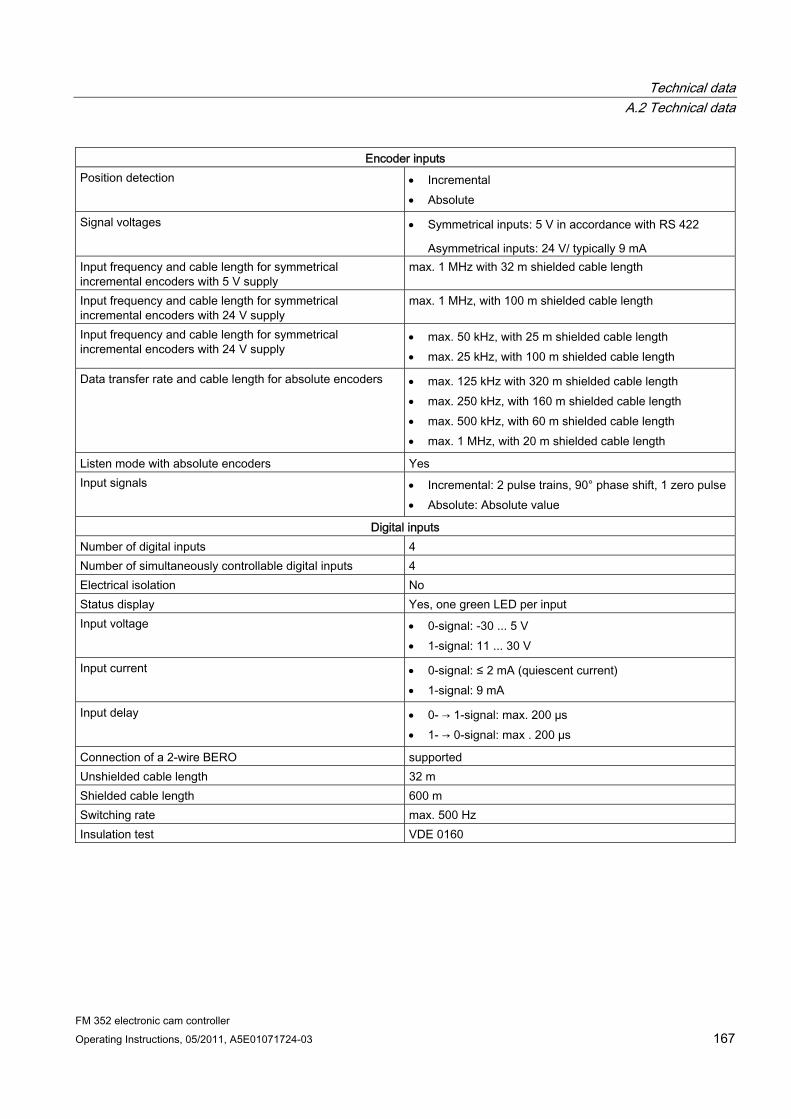
Technical data A.2 Technical data
FM 352 electronic cam controller Operating Instructions, 05/2011, A5E01071724-03 167
Encoder inputs Position detection Incremental
Absolute
Signal voltages Symmetrical inputs: 5 V in accordance with RS 422
Asymmetrical inputs: 24 V/ typically 9 mA Input frequency and cable length for symmetrical incremental encoders with 5 V supply
max. 1 MHz with 32 m shielded cable length
Input frequency and cable length for symmetrical incremental encoders with 24 V supply
max. 1 MHz, with 100 m shielded cable length
Input frequency and cable length for symmetrical incremental encoders with 24 V supply
max. 50 kHz, with 25 m shielded cable length max. 25 kHz, with 100 m shielded cable length
Data transfer rate and cable length for absolute encoders max. 125 kHz with 320 m shielded cable length max. 250 kHz, with 160 m shielded cable length max. 500 kHz, with 60 m shielded cable length max. 1 MHz, with 20 m shielded cable length
Listen mode with absolute encoders Yes Input signals Incremental: 2 pulse trains, 90° phase shift, 1 zero pulse
Absolute: Absolute value
Digital inputs Number of digital inputs 4 Number of simultaneously controllable digital inputs 4 Electrical isolation No Status display Yes, one green LED per input Input voltage 0-signal: -30 ... 5 V
1-signal: 11 ... 30 V
Input current 0-signal: ≤ 2 mA (quiescent current) 1-signal: 9 mA
Input delay 0- → 1-signal: max. 200 µs 1- → 0-signal: max . 200 µs
Connection of a 2-wire BERO supported Unshielded cable length 32 m Shielded cable length 600 m Switching rate max. 500 Hz Insulation test VDE 0160
Technical data A.2 Technical data
FM 352 electronic cam controller 168 Operating Instructions, 05/2011, A5E01071724-03
Digital outputs Number of outputs 13 Electrical isolation No Status display Yes, one green LED per output Output current 0-signal: 0.5 mA
1-signal: 0.5 A at 100% concurrence (permitted range: 5 ... 600 mA)
Lamp load: 5 W
Output delay when output current = 0.5 A 0- → 1-signal: max. 300 µs 1- → 0-signal: max. 300 µs
Signal level for 1-signal L+: -0.8 V Control of a digital input Yes Control of a count input no, due to 50 µs pulse error Short-circuit protection Yes, thermal, clocked
Switching threshold 1.8 A Limiting of inductive switch-off voltage typically L+ -48 V Switching rate resistive load: max. 500 Hz
inductive load: max. 0.5 Hz
Cumulative current of digital outputs with horizontal installation of S7-300
Demand factor 100%: at 20 °C: 6 A at 60 °C: 3 A
Cumulative current of digital outputs with vertical installation of S7-300
Demand factor 100%: at 40 °C: 3 A
Unshielded cable length max. 100 m Shielded cable length 600 m Insulation test VDE 0160
Note
If the 24 V power supply is connected using a mechanical contact, the FM 352 transfers a pulse to the outputs. The pulse may assume a length of 50 µs within the permissible output current range. You must take this into account when using the FM 352 in combination with high-speed counters.
FM 352 electronic cam controller Operating Instructions, 05/2011, A5E01071724-03 169
Connection Diagrams BB.1 Encoder types
Overview The table below describes the encoders supported by FM 352. The connection diagrams for these encoders are described in this chapter:
Encoder type Connecting cable Comment
Incremental encoder Siemens 6FX 2001-2⃞⃞⃞⃞
4 x 2 x 0.25 + 2 x 1 mm2 Incremental encoder: Vp=5 V, RS422
Incremental encoder Siemens 6FX 2001-2⃞⃞⃞⃞
4 x 2 x 0.5 mm2 Incremental encoder: Vp=24 V, RS422
Incremental encoder Siemens 6FX 2001-4⃞⃞⃞⃞
4 x 2 x 0.5 mm2 Incremental encoder: Vp=24 V, HTL
Absolute encoder Siemens 6FX 2001-5⃞⃞⃞⃞
4 x 2 x 0.5 mm2 Absolute encoder: Vp=24 V, SSI
Connection Diagrams B.2 Connection Diagram for Incremental Encoder Siemens 6FX 2001-2 (Up=5V; RS 422)
FM 352 electronic cam controller 170 Operating Instructions, 05/2011, A5E01071724-03
B.2 Connection Diagram for Incremental Encoder Siemens 6FX 2001-2 (Up=5V; RS 422)
Connection diagram
Figure B-1 Connection diagram for incremental encoder Siemens 6FX 2001-2⃞⃞⃞⃞ (Up=5 V:
RS422)
Circular connector
12-pin socket, Siemens 6FX2003-0SU12
Figure B-2 Circular connector, terminal end (solder side)
Connection Diagrams B.2 Connection Diagram for Incremental Encoder Siemens 6FX 2001-2 (Up=5V; RS 422)
FM 352 electronic cam controller Operating Instructions, 05/2011, A5E01071724-03 171
Sub D connector
15-pin sub D connector, metallized housing with screw interlock 6FC9 341-1HC
Figure B-3 Sub D connector, terminal end (solder side)
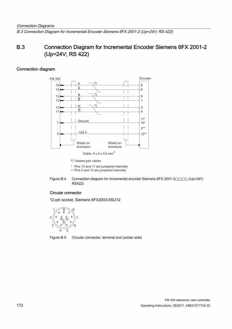
Connection Diagrams B.3 Connection Diagram for Incremental Encoder Siemens 6FX 2001-2 (Up=24V; RS 422)
FM 352 electronic cam controller 172 Operating Instructions, 05/2011, A5E01071724-03
B.3 Connection Diagram for Incremental Encoder Siemens 6FX 2001-2 (Up=24V; RS 422)
Connection diagram
_
_
_
Figure B-4 Connection diagram for incremental encoder Siemens 6FX 2001-2⃞⃞⃞⃞ (Up=24V;
RS422)
Circular connector
12-pin socket, Siemens 6FX2003-0SU12
Figure B-5 Circular connector, terminal end (solder side)

Connection Diagrams B.3 Connection Diagram for Incremental Encoder Siemens 6FX 2001-2 (Up=24V; RS 422)
FM 352 electronic cam controller Operating Instructions, 05/2011, A5E01071724-03 173
Sub D connector
15-pin sub D connector, metallized housing with screw interlock 6FC9 341-1HC
Figure B-6 Sub D connector, terminal end (solder side)

Connection Diagrams B.4 Wiring Diagram of the Incremental Encoder Siemens 6FX 2001-4 (Up = 24 V; HTL)
FM 352 electronic cam controller 174 Operating Instructions, 05/2011, A5E01071724-03
B.4 Wiring Diagram of the Incremental Encoder Siemens 6FX 2001-4 (Up = 24 V; HTL)
Connection diagram
Figure B-7 Connection diagram for incremental encoder Siemens 6FX 2001-4⃞⃞⃞⃞ (Up=24V;
HTL)
Circular connector
12-pin Siemens socket 6FX2003-0SU12
Figure B-8 Circular connector, terminal end (solder side)
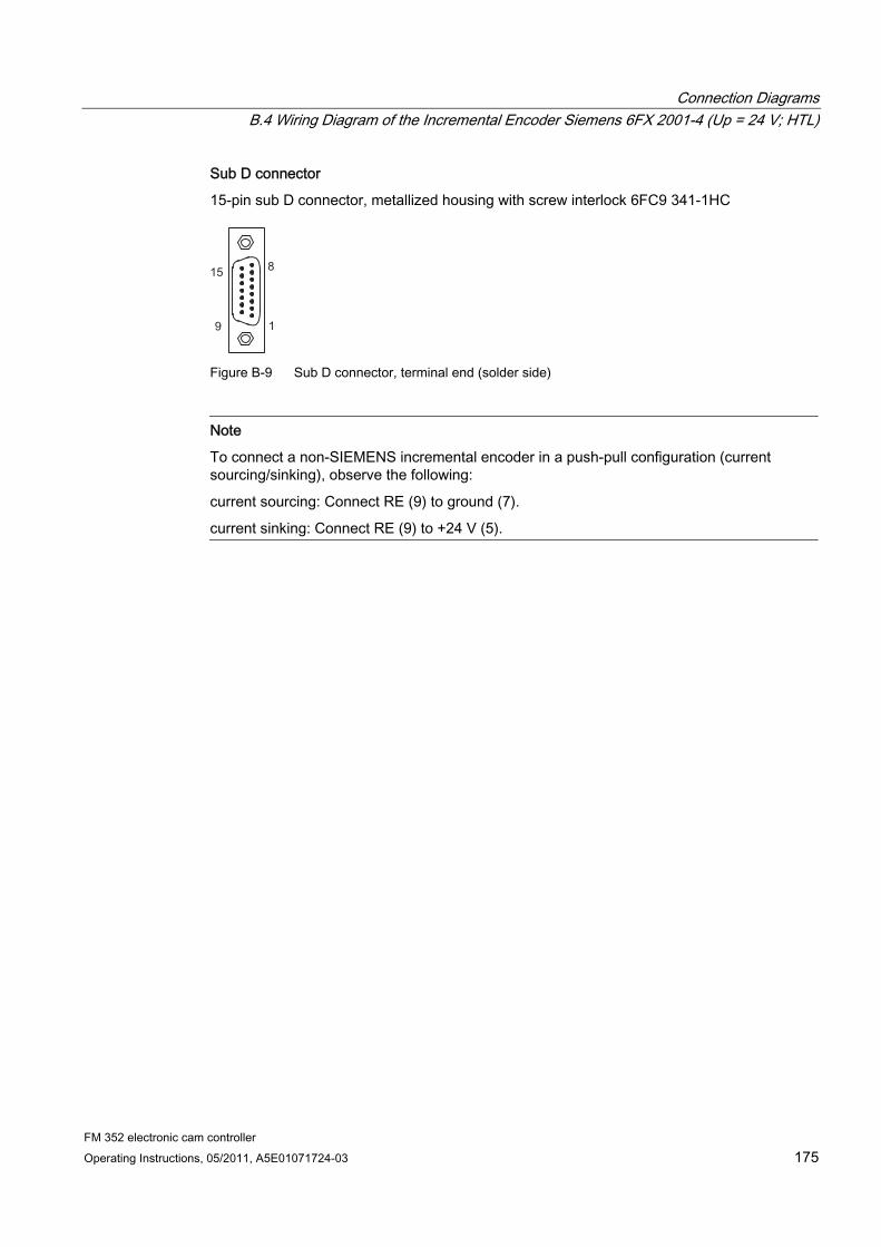
Connection Diagrams B.4 Wiring Diagram of the Incremental Encoder Siemens 6FX 2001-4 (Up = 24 V; HTL)
FM 352 electronic cam controller Operating Instructions, 05/2011, A5E01071724-03 175
Sub D connector
15-pin sub D connector, metallized housing with screw interlock 6FC9 341-1HC
Figure B-9 Sub D connector, terminal end (solder side)
Note
To connect a non-SIEMENS incremental encoder in a push-pull configuration (current sourcing/sinking), observe the following:
current sourcing: Connect RE (9) to ground (7).
current sinking: Connect RE (9) to +24 V (5).
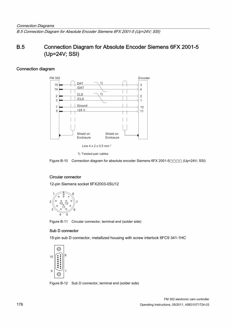
Connection Diagrams B.5 Connection Diagram for Absolute Encoder Siemens 6FX 2001-5 (Up=24V; SSI)
FM 352 electronic cam controller 176 Operating Instructions, 05/2011, A5E01071724-03
B.5 Connection Diagram for Absolute Encoder Siemens 6FX 2001-5 (Up=24V; SSI)
Connection diagram
Figure B-10 Connection diagram for absolute encoder Siemens 6FX 2001-5⃞⃞⃞⃞ (Up=24V; SSI)
Circular connector
12-pin Siemens socket 6FX2003-0SU12
Figure B-11 Circular connector, terminal end (solder side)
Sub D connector
15-pin sub D connector, metallized housing with screw interlock 6FC9 341-1HC
Figure B-12 Sub D connector, terminal end (solder side)
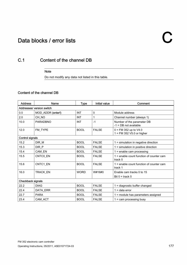
FM 352 electronic cam controller Operating Instructions, 05/2011, A5E01071724-03 177
Data blocks / error lists CC.1 Content of the channel DB
Note
Do not modify any data not listed in this table.
Content of the channel DB
Address Name Type Initial value Comment Addresses/ version switch 0.0 MOD_ADDR (enter!) INT 0 Module address 2.0 CH_NO INT 1 Channel number (always 1) 10.0 PARADBNO
INT -1 Number of the parameter DB
-1 = DB not available 12.0 FM_TYPE BOOL FALSE 0 = FM 352 up to V4.0
1 = FM 352 V5.0 or higher Control signals 15.2 DIR_M BOOL FALSE 1 = simulation in negative direction 15.3 DIR_P BOOL FALSE 1 = simulation in positive direction 15.4 CAM_EN BOOL FALSE 1 = enable cam processing 15.5 CNTC0_EN BOOL FALSE 1 = enable count function of counter cam
track 0 15.6 CNTC1_EN BOOL FALSE 1 = enable count function of counter cam
track 1 16.0 TRACK_EN WORD W#16#0 Enable cam tracks 0 to 15
Bit 0 = track 0 Checkback signals 22.2 DIAG BOOL FALSE 1 = diagnostic buffer changed 22.4 DATA_ERR BOOL FALSE 1 = data error 22.7 PARA BOOL FALSE 1 = module has parameters assigned 23.4 CAM_ACT BOOL FALSE 1 = cam processing busy
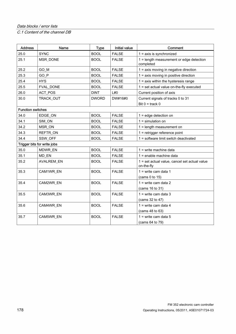
Data blocks / error lists C.1 Content of the channel DB
FM 352 electronic cam controller 178 Operating Instructions, 05/2011, A5E01071724-03
Address Name Type Initial value Comment 25.0 SYNC BOOL FALSE 1 = axis is synchronized 25.1 MSR_DONE BOOL FALSE 1 = length measurement or edge detection
completed 25.2 GO_M BOOL FALSE 1 = axis moving in negative direction 25.3 GO_P BOOL FALSE 1 = axis moving in positive direction 25.4 HYS BOOL FALSE 1 = axis within the hysteresis range 25.5 FVAL_DONE BOOL FALSE 1 = set actual value on-the-fly executed 26.0 ACT_POS DINT L#0 Current position of axis 30.0 TRACK_OUT DWORD DW#16#0 Current signals of tracks 0 to 31
Bit 0 = track 0 Function switches 34.0 EDGE_ON BOOL FALSE 1 = edge detection on 34.1 SIM_ON BOOL FALSE 1 = simulation on 34.2 MSR_ON BOOL FALSE 1 = length measurement on 34.3 REFTR_ON BOOL FALSE 1 = retrigger reference point 34.4 SSW_OFF BOOL FALSE 1 = software limit switch deactivated Trigger bits for write jobs 35.0 MDWR_EN BOOL FALSE 1 = write machine data 35.1 MD_EN BOOL FALSE 1 = enable machine data 35.2 AVALREM_EN BOOL FALSE 1 = set actual value, cancel set actual value
on-the-fly 35.3 CAM1WR_EN BOOL FALSE 1 = write cam data 1
(cams 0 to 15) 35.4 CAM2WR_EN BOOL FALSE 1 = write cam data 2
(cams 16 to 31) 35.5 CAM3WR_EN BOOL FALSE 1 = write cam data 3
(cams 32 to 47) 35.6 CAM4WR_EN BOOL FALSE 1 = write cam data 4
(cams 48 to 63) 35.7 CAM5WR_EN BOOL FALSE 1 = write cam data 5
(cams 64 to 79)
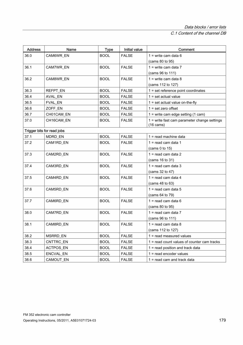
Data blocks / error lists C.1 Content of the channel DB
FM 352 electronic cam controller Operating Instructions, 05/2011, A5E01071724-03 179
Address Name Type Initial value Comment 36.0 CAM6WR_EN BOOL FALSE 1 = write cam data 6
(cams 80 to 95) 36.1 CAM7WR_EN BOOL FALSE 1 = write cam data 7
(cams 96 to 111) 36.2 CAM8WR_EN BOOL FALSE 1 = write cam data 8
(cams 112 to 127) 36.3 REFPT_EN BOOL FALSE 1 = set reference point coordinates 36.4 AVAL_EN BOOL FALSE 1 = set actual value 36.5 FVAL_EN BOOL FALSE 1 = set actual value on-the-fly 36.6 ZOFF_EN BOOL FALSE 1 = set zero offset 36.7 CH01CAM_EN BOOL FALSE 1 = write cam edge setting (1 cam) 37.0 CH16CAM_EN BOOL FALSE 1 = write fast cam parameter change settings
(16 cams) Trigger bits for read jobs 37.1 MDRD_EN BOOL FALSE 1 = read machine data 37.2 CAM1RD_EN BOOL FALSE 1 = read cam data 1
(cams 0 to 15) 37.3 CAM2RD_EN BOOL FALSE 1 = read cam data 2
(cams 16 to 31) 37.4 CAM3RD_EN BOOL FALSE 1 = read cam data 3
(cams 32 to 47) 37.5 CAM4RD_EN BOOL FALSE 1 = read cam data 4
(cams 48 to 63) 37.6 CAM5RD_EN BOOL FALSE 1 = read cam data 5
(cams 64 to 79) 37.7 CAM6RD_EN BOOL FALSE 1 = read cam data 6
(cams 80 to 95) 38.0 CAM7RD_EN BOOL FALSE 1 = read cam data 7
(cams 96 to 111) 38.1 CAM8RD_EN BOOL FALSE 1 = read cam data 8
(cams 112 to 127) 38.2 MSRRD_EN BOOL FALSE 1 = read measured values 38.3 CNTTRC_EN BOOL FALSE 1 = read count values of counter cam tracks 38.4 ACTPOS_EN BOOL FALSE 1 = read position and track data 38.5 ENCVAL_EN BOOL FALSE 1 = read encoder values 38.6 CAMOUT_EN BOOL FALSE 1 = read cam and track data
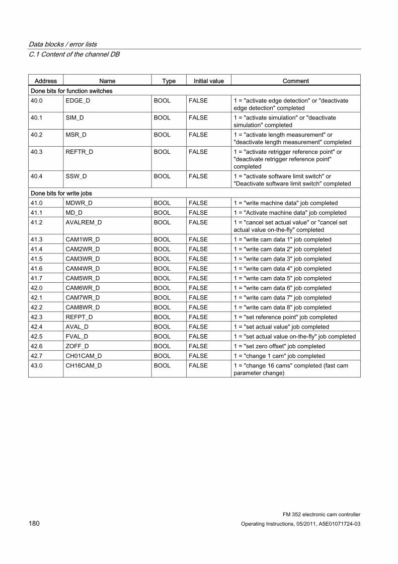
Data blocks / error lists C.1 Content of the channel DB
FM 352 electronic cam controller 180 Operating Instructions, 05/2011, A5E01071724-03
Address Name Type Initial value Comment Done bits for function switches 40.0 EDGE_D BOOL FALSE 1 = "activate edge detection" or "deactivate
edge detection" completed 40.1 SIM_D BOOL FALSE 1 = "activate simulation" or "deactivate
simulation" completed 40.2 MSR_D BOOL FALSE 1 = "activate length measurement" or
"deactivate length measurement" completed 40.3 REFTR_D BOOL FALSE 1 = "activate retrigger reference point" or
"deactivate retrigger reference point" completed
40.4 SSW_D BOOL FALSE 1 = "activate software limit switch" or "Deactivate software limit switch" completed
Done bits for write jobs 41.0 MDWR_D BOOL FALSE 1 = "write machine data" job completed 41.1 MD_D BOOL FALSE 1 = "Activate machine data" job completed 41.2 AVALREM_D BOOL FALSE 1 = "cancel set actual value" or "cancel set
actual value on-the-fly" completed 41.3 CAM1WR_D BOOL FALSE 1 = "write cam data 1" job completed 41.4 CAM2WR_D BOOL FALSE 1 = "write cam data 2" job completed 41.5 CAM3WR_D BOOL FALSE 1 = "write cam data 3" job completed 41.6 CAM4WR_D BOOL FALSE 1 = "write cam data 4" job completed 41.7 CAM5WR_D BOOL FALSE 1 = "write cam data 5" job completed 42.0 CAM6WR_D BOOL FALSE 1 = "write cam data 6" job completed 42.1 CAM7WR_D BOOL FALSE 1 = "write cam data 7" job completed 42.2 CAM8WR_D BOOL FALSE 1 = "write cam data 8" job completed 42.3 REFPT_D BOOL FALSE 1 = "set reference point" job completed 42.4 AVAL_D BOOL FALSE 1 = "set actual value" job completed 42.5 FVAL_D BOOL FALSE 1 = "set actual value on-the-fly" job completed 42.6 ZOFF_D BOOL FALSE 1 = "set zero offset" job completed 42.7 CH01CAM_D BOOL FALSE 1 = "change 1 cam" job completed 43.0 CH16CAM_D BOOL FALSE 1 = "change 16 cams" completed (fast cam
parameter change)
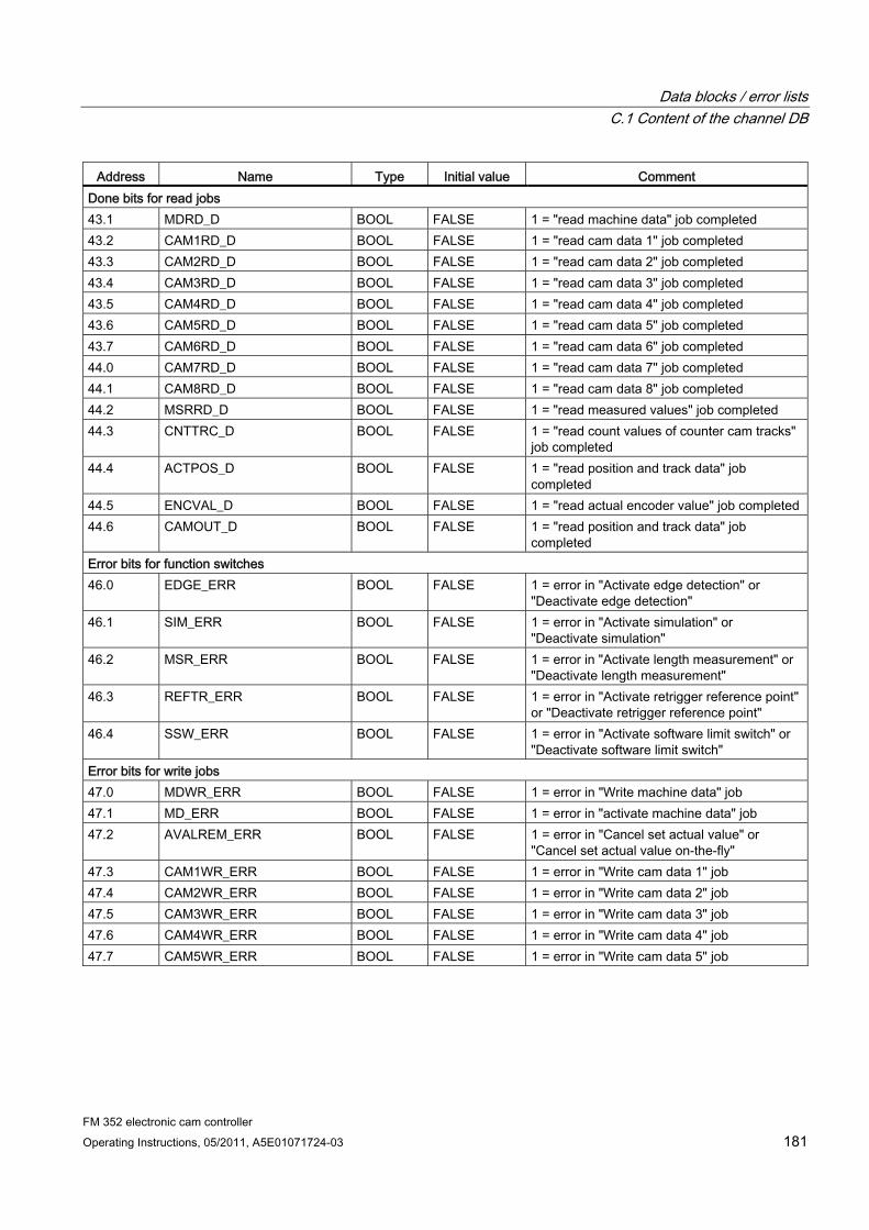
Data blocks / error lists C.1 Content of the channel DB
FM 352 electronic cam controller Operating Instructions, 05/2011, A5E01071724-03 181
Address Name Type Initial value Comment Done bits for read jobs 43.1 MDRD_D BOOL FALSE 1 = "read machine data" job completed 43.2 CAM1RD_D BOOL FALSE 1 = "read cam data 1" job completed 43.3 CAM2RD_D BOOL FALSE 1 = "read cam data 2" job completed 43.4 CAM3RD_D BOOL FALSE 1 = "read cam data 3" job completed 43.5 CAM4RD_D BOOL FALSE 1 = "read cam data 4" job completed 43.6 CAM5RD_D BOOL FALSE 1 = "read cam data 5" job completed 43.7 CAM6RD_D BOOL FALSE 1 = "read cam data 6" job completed 44.0 CAM7RD_D BOOL FALSE 1 = "read cam data 7" job completed 44.1 CAM8RD_D BOOL FALSE 1 = "read cam data 8" job completed 44.2 MSRRD_D BOOL FALSE 1 = "read measured values" job completed 44.3 CNTTRC_D BOOL FALSE 1 = "read count values of counter cam tracks"
job completed 44.4 ACTPOS_D BOOL FALSE 1 = "read position and track data" job
completed 44.5 ENCVAL_D BOOL FALSE 1 = "read actual encoder value" job completed 44.6 CAMOUT_D BOOL FALSE 1 = "read position and track data" job
completed Error bits for function switches 46.0 EDGE_ERR BOOL FALSE 1 = error in "Activate edge detection" or
"Deactivate edge detection" 46.1 SIM_ERR BOOL FALSE 1 = error in "Activate simulation" or
"Deactivate simulation" 46.2 MSR_ERR BOOL FALSE 1 = error in "Activate length measurement" or
"Deactivate length measurement" 46.3 REFTR_ERR BOOL FALSE 1 = error in "Activate retrigger reference point"
or "Deactivate retrigger reference point" 46.4 SSW_ERR BOOL FALSE 1 = error in "Activate software limit switch" or
"Deactivate software limit switch" Error bits for write jobs 47.0 MDWR_ERR BOOL FALSE 1 = error in "Write machine data" job 47.1 MD_ERR BOOL FALSE 1 = error in "activate machine data" job 47.2 AVALREM_ERR BOOL FALSE 1 = error in "Cancel set actual value" or
"Cancel set actual value on-the-fly" 47.3 CAM1WR_ERR BOOL FALSE 1 = error in "Write cam data 1" job 47.4 CAM2WR_ERR BOOL FALSE 1 = error in "Write cam data 2" job 47.5 CAM3WR_ERR BOOL FALSE 1 = error in "Write cam data 3" job 47.6 CAM4WR_ERR BOOL FALSE 1 = error in "Write cam data 4" job 47.7 CAM5WR_ERR BOOL FALSE 1 = error in "Write cam data 5" job
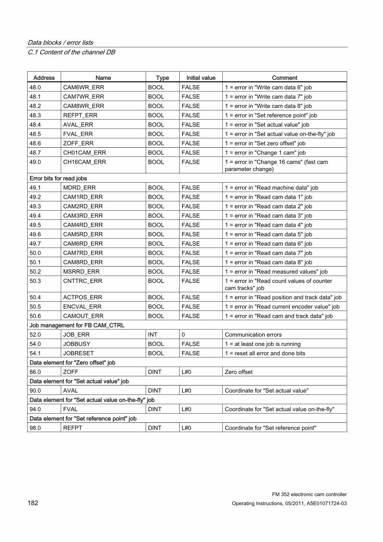
Data blocks / error lists C.1 Content of the channel DB
FM 352 electronic cam controller 182 Operating Instructions, 05/2011, A5E01071724-03
Address Name Type Initial value Comment 48.0 CAM6WR_ERR BOOL FALSE 1 = error in "Write cam data 6" job 48.1 CAM7WR_ERR BOOL FALSE 1 = error in "Write cam data 7" job 48.2 CAM8WR_ERR BOOL FALSE 1 = error in "Write cam data 8" job 48.3 REFPT_ERR BOOL FALSE 1 = error in "Set reference point" job 48.4 AVAL_ERR BOOL FALSE 1 = error in "Set actual value" job 48.5 FVAL_ERR BOOL FALSE 1 = error in "Set actual value on-the-fly" job 48.6 ZOFF_ERR BOOL FALSE 1 = error in "Set zero offset" job 48.7 CH01CAM_ERR BOOL FALSE 1 = error in "Change 1 cam" job 49.0 CH16CAM_ERR BOOL FALSE 1 = error in "Change 16 cams" (fast cam
parameter change) Error bits for read jobs 49.1 MDRD_ERR BOOL FALSE 1 = error in "Read machine data" job 49.2 CAM1RD_ERR BOOL FALSE 1 = error in "Read cam data 1" job 49.3 CAM2RD_ERR BOOL FALSE 1 = error in "Read cam data 2" job 49.4 CAM3RD_ERR BOOL FALSE 1 = error in "Read cam data 3" job 49.5 CAM4RD_ERR BOOL FALSE 1 = error in "Read cam data 4" job 49.6 CAM5RD_ERR BOOL FALSE 1 = error in "Read cam data 5" job 49.7 CAM6RD_ERR BOOL FALSE 1 = error in "Read cam data 6" job 50.0 CAM7RD_ERR BOOL FALSE 1 = error in "Read cam data 7" job 50.1 CAM8RD_ERR BOOL FALSE 1 = error in "Read cam data 8" job 50.2 MSRRD_ERR BOOL FALSE 1 = error in "Read measured values" job 50.3 CNTTRC_ERR BOOL FALSE 1 = error in "Read count values of counter
cam tracks" job 50.4 ACTPOS_ERR BOOL FALSE 1 = error in "Read position and track data" job 50.5 ENCVAL_ERR BOOL FALSE 1 = error in "Read current encoder value" job 50.6 CAMOUT_ERR BOOL FALSE 1 = error in "Read cam and track data" job Job management for FB CAM_CTRL 52.0 JOB_ERR INT 0 Communication errors 54.0 JOBBUSY BOOL FALSE 1 = at least one job is running 54.1 JOBRESET BOOL FALSE 1 = reset all error and done bits Data element for "Zero offset" job 86.0 ZOFF DINT L#0 Zero offset Data element for "Set actual value" job 90.0 AVAL DINT L#0 Coordinate for "Set actual value" Data element for "Set actual value on-the-fly" job 94.0 FVAL DINT L#0 Coordinate for "Set actual value on-the-fly" Data element for "Set reference point" job 98.0 REFPT DINT L#0 Coordinate for "Set reference point"

Data blocks / error lists C.1 Content of the channel DB
FM 352 electronic cam controller Operating Instructions, 05/2011, A5E01071724-03 183
Address Name Type Initial value Comment Data for "Change cam edges" job 102.0 CAM_NO INT 0 Cam number 104.0 CAM_START DINT L#0 Cam start 108.0 CAM_END DINT L#0 Cam end Data for "Length measurement/edge detection" job 112.0 BEG_VAL DINT L#0 Initial value 116.0 END_VAL DINT L#0 End value 120.0 LEN_VAL DINT L#0 Length Data for "Read count values" job 124.0 CNT_TRC0 INT 0 Current count value of counter cam track 0 126.0 CNT_TRC1 INT 0 Current count value of counter cam track 1 Data for "Read position and track data" job 128.0 ACTPOS DINT L#0 Current position 132.0 ACTSPD DINT L#0 Current velocity 136.0 TRACK_ID DWORD DW#16#0 Track identifier bits of tracks 0 to 31 Data for "Read encoder data" job 140.0 ENCVAL DINT L#0 Encoder value 144.0 ZEROVAL DINT L#0 Count value at the last zero mark 148.0 ENC_ADJ DINT L#0 Absolute encoder adjustment Data for "Read cam and track data" job 152.0 CAM_00_31 DWORD DW#16#0 Cam identifier bits for cams 0 to 31 156.0 CAM_32_63 DWORD DW#16#0 Cam identifier bits for cams 32 to 63 160.0 CAM_64_95 DWORD DW#16#0 Cam identifier bits for cams 64 to 95 164.0 CAM_96_127 DWORD DW#16#0 Cam identifier bits for cams 96 to 127 168.0 TRACK_ID1 DWORD DW#16#0 Track identifier bits of tracks 0 to 31 172.0 ACTPOS1 DINT L#0 Current position Data for "Fast cam parameter change" job 176.0 C_QTY BYTE B#16#0 Number of cams to modify 177.0 DIS_CHECK BOOL FALSE 1 = disable data check 180.0 CAM ARRAY
[0...15] STRUCT
Note: The following structure must be completed for each cam to be modified
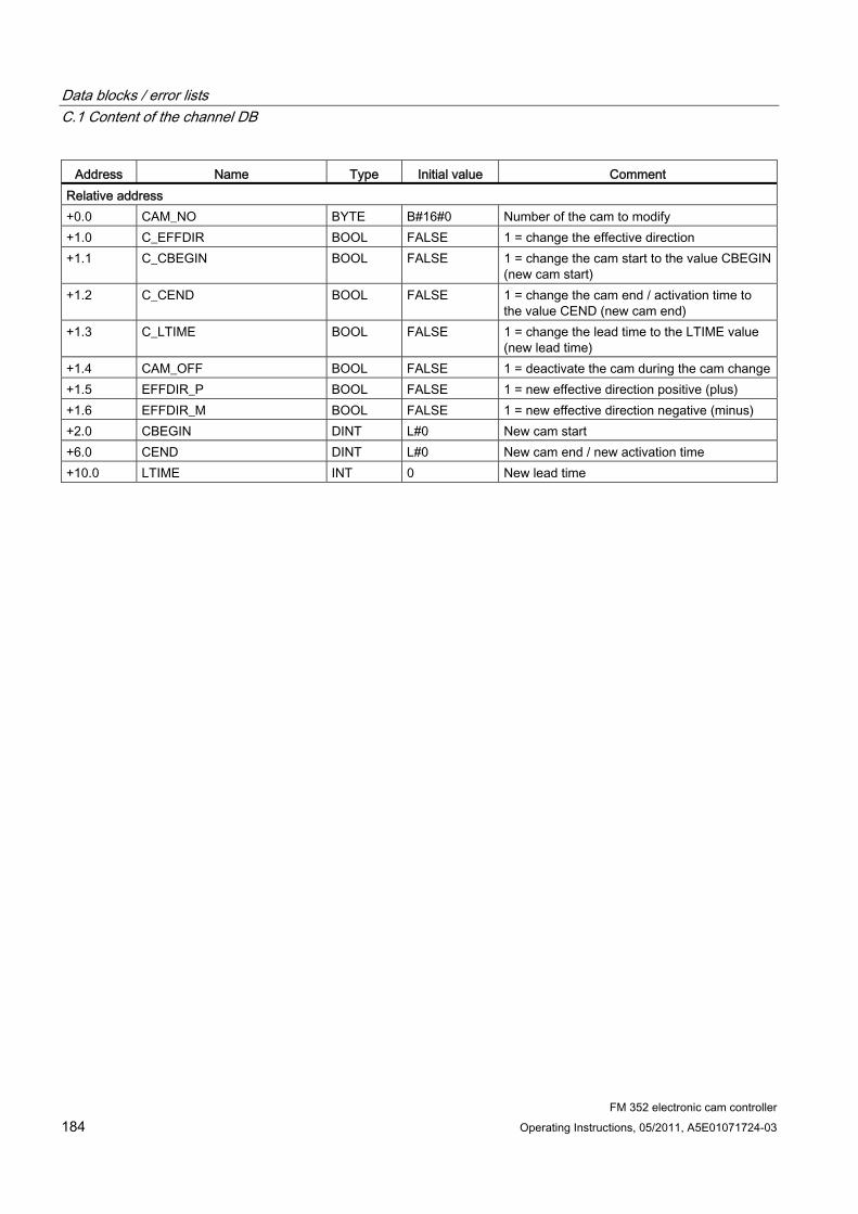
Data blocks / error lists C.1 Content of the channel DB
FM 352 electronic cam controller 184 Operating Instructions, 05/2011, A5E01071724-03
Address Name Type Initial value Comment Relative address +0.0 CAM_NO BYTE B#16#0 Number of the cam to modify +1.0 C_EFFDIR BOOL FALSE 1 = change the effective direction +1.1 C_CBEGIN BOOL FALSE 1 = change the cam start to the value CBEGIN
(new cam start) +1.2 C_CEND BOOL FALSE 1 = change the cam end / activation time to
the value CEND (new cam end) +1.3 C_LTIME BOOL FALSE 1 = change the lead time to the LTIME value
(new lead time) +1.4 CAM_OFF BOOL FALSE 1 = deactivate the cam during the cam change+1.5 EFFDIR_P BOOL FALSE 1 = new effective direction positive (plus) +1.6 EFFDIR_M BOOL FALSE 1 = new effective direction negative (minus) +2.0 CBEGIN DINT L#0 New cam start +6.0 CEND DINT L#0 New cam end / new activation time +10.0 LTIME INT 0 New lead time
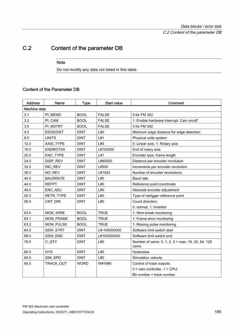
Data blocks / error lists C.2 Content of the parameter DB
FM 352 electronic cam controller Operating Instructions, 05/2011, A5E01071724-03 185
C.2 Content of the parameter DB
Note
Do not modify any data not listed in this table.
Content of the Parameter DB
Address Name Type Start value Comment Machine data 3.1 PI_MEND BOOL FALSE 0 for FM 352 3.2 PI_CAM BOOL FALSE 1: Enable hardware interrupt: Cam on/off 3.5 PI_MSTRT BOOL FALSE 0 for FM 352 4.0 EDGEDIST DINT L#0 Minimum edge distance for edge detection 8.0 UNITS DINT L#1 Physical units system 12.0 AXIS_TYPE DINT L#0 0: Linear axis, 1: Rotary axis 16.0 ENDROTAX DINT L#100000 End of rotary axis 20.0 ENC_TYPE DINT L#1 Encoder type, frame length 24.0 DISP_REV DINT L#80000 Distance per encoder revolution 32.0 INC_REV DINT L#500 Increments per encoder revolution 36.0 NO_REV DINT L#1024 Number of encoder revolutions 40.0 BAUDRATE DINT L#0 Baud rate 44.0 REFPT DINT L#0 Reference point coordinate 48.0 ENC_ADJ DINT L#0 Absolute encoder adjustment 52.0 RETR_TYPE DINT L#0 Type of retrigger reference point 56.0 CNT_DIR DINT L#0 Count direction:
0: normal, 1: inverted 63.0 MON_WIRE BOOL TRUE 1: Wire-break monitoring 63.1 MON_FRAME BOOL TRUE 1: Frame error monitoring 63.2 MON_PULSE BOOL TRUE 1: Missing pulse monitoring 64.0 SSW_STRT DINT L#-100000000 Software limit switch start 68.0 SSW_END DINT L#100000000 Software limit switch end 76.0 C_QTY DINT L#0 Number of cams: 0, 1, 2, 3 = max. 16, 32, 64, 128
cams 80.0 HYS DINT L#0 Hysteresis 84.0 SIM_SPD DINT L#0 Simulation velocity 90.0 TRACK_OUT WORD W#16#0 Control of track outputs:
0 = cam controller, 1 = CPU; Bit number = track number
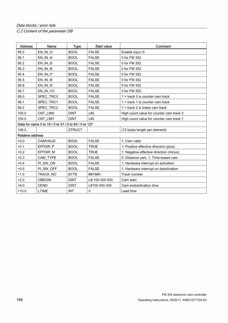
Data blocks / error lists C.2 Content of the parameter DB
FM 352 electronic cam controller 186 Operating Instructions, 05/2011, A5E01071724-03
Address Name Type Start value Comment 95.0 EN_IN_I3 BOOL FALSE Enable input I3 95.1 EN_IN_I4 BOOL FALSE 0 for FM 352 95.2 EN_IN_I5 BOOL FALSE 0 for FM 352 95.3 EN_IN_I6 BOOL FALSE 0 for FM 352 95.4 EN_IN_I7 BOOL FALSE 0 for FM 352 95.5 EN_IN_I8 BOOL FALSE 0 for FM 352 95.6 EN_IN_I9 BOOL FALSE 0 for FM 352 95.7 EN_IN_I10 BOOL FALSE 0 for FM 352 99.0 SPEC_TRC0 BOOL FALSE 1 = track 0 is counter cam track 99.1 SPEC_TRC1 BOOL FALSE 1 = track 1 is counter cam track 99.2 SPEC_TRC2 BOOL FALSE 1 = track 2 is brake cam track 100.0 CNT_LIM0 DINT L#2 High count value for counter cam track 0 104.0 CNT_LIM1 DINT L#2 High count value for counter cam track 1 Data for cams 0 to 15 / 0 to 31 / 0 to 63 / 0 to 127 108.0 STRUCT (12 bytes length per element) Relative address +0.0 CAMVALID BOOL FALSE 1: Cam valid +0.1 EFFDIR_P BOOL TRUE 1: Positive effective direction (plus) +0.2 EFFDIR_M BOOL TRUE 1: Negative effective direction (minus) +0.3 CAM_TYPE BOOL FALSE 0: Distance cam, 1: Time-based cam +0.4 PI_SW_ON BOOL FALSE 1: Hardware interrupt on activation +0.5 PI_SW_OFF BOOL FALSE 1: Hardware interrupt on deactivation +1.0 TRACK_NO BYTE B#16#0 Track number +2.0 CBEGIN DINT L#-100 000 000 Cam start +6.0 CEND DINT L#100 000 000 Cam end/activation time +10.0 LTIME INT 0 Lead time
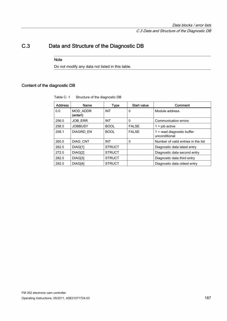
Data blocks / error lists C.3 Data and Structure of the Diagnostic DB
FM 352 electronic cam controller Operating Instructions, 05/2011, A5E01071724-03 187
C.3 Data and Structure of the Diagnostic DB
Note
Do not modify any data not listed in this table.
Content of the diagnostic DB
Table C- 1 Structure of the diagnostic DB
Address Name Type Start value Comment 0.0 MOD_ADDR
(enter!) INT 0 Module address
256.0 JOB_ERR INT 0 Communication errors 258.0 JOBBUSY BOOL FALSE 1 = job active 258.1 DIAGRD_EN BOOL FALSE 1 = read diagnostic buffer
unconditional 260.0 DIAG_CNT INT 0 Number of valid entries in the list 262.0 DIAG[1] STRUCT Diagnostic data latest entry 272.0 DIAG[2] STRUCT Diagnostic data second entry 282.0 DIAG[3] STRUCT Diagnostic data third entry 292.0 DIAG[4] STRUCT Diagnostic data oldest entry

Data blocks / error lists C.3 Data and Structure of the Diagnostic DB
FM 352 electronic cam controller 188 Operating Instructions, 05/2011, A5E01071724-03
Structure of the Diagnostic Entry The diagnostic entry DIAG[n] is structured as follows:
Table C- 2 Structure of the diagnostic entry DIAG[n]
Address Name Type Start value Comment +0.0 STATE BOOL FALSE 0 = outgoing event
1 = incoming event +0.1 INTF BOOL FALSE 1 = Internal error +0.2 EXTF BOOL FALSE 1 = external error +2.0 FCL INT 0 Error class:
1: Operating error 4: Data error 5: Machine data error 7: Cam data error 15: Messages 128: Diagnostic errors
+4.0 FNO INT 0 Error numbers 0 to 255 +6.0 CH_NO INT 0 Channel number (always 1) +8.0 CAMNO INT 0 Cam numbers 0 to 127 with error class = cam data
error
List of JOB_ERR messages JOB_ERR (hex)
JOB_ERR (dec)
JOB_ERR (int)
Meaning
80A0 32928 -32608 Negative acknowledgment when reading from module. Module removed during read operation or module defective.
80A1 32929 -32607 Negative acknowledgment when writing to module. Module removed during write operation or module defective.
80A2 32930 -32606 Protocol error on Layer 2 (data transfer interrupted within PROFINET / PROFIBUS DP, for example, due to wire break, missing connector, parameter assignment error, etc.)
80A3 32931 -32605 Protocol error at user interface/user (data transfer interrupted within PROFINET / PROFIBUS DP, for example, due to wire break, missing connector, parameter assignment error, etc.)
80A4 32932 -32604 Communication problem on K bus 80B1 32945 -32591 Specified length wrong. Faulty FM_TYPE parameter setting at
the channel DB for the module in use. 80B2 32946 -32590 The configured slot is empty. 80B3 32947 -32589 Actual module type does not match configured module type. 80C0 32960 -32576 The module has not yet prepared the data to be read. 80C1 32961 -32575 The data of a write job of the same type have not yet been
processed on the module. 80C2 32962 -32574 The module is currently processing the maximum number of
jobs. 80C3 32963 -32573 Required resources (memory etc.) currently in use.
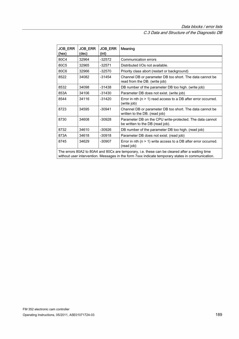
Data blocks / error lists C.3 Data and Structure of the Diagnostic DB
FM 352 electronic cam controller Operating Instructions, 05/2011, A5E01071724-03 189
JOB_ERR (hex)
JOB_ERR (dec)
JOB_ERR (int)
Meaning
80C4 32964 -32572 Communication errors 80C5 32965 -32571 Distributed I/Os not available. 80C6 32966 -32570 Priority class abort (restart or background) 8522 34082 -31454 Channel DB or parameter DB too short. The data cannot be
read from the DB. (write job) 8532 34098 -31438 DB number of the parameter DB too high. (write job) 853A 34106 -31430 Parameter DB does not exist. (write job) 8544 34116 -31420 Error in nth (n > 1) read access to a DB after error occurred.
(write job) 8723 34595 -30941 Channel DB or parameter DB too short. The data cannot be
written to the DB. (read job) 8730 34608 -30928 Parameter DB on the CPU write-protected. The data cannot
be written to the DB (read job). 8732 34610 -30926 DB number of the parameter DB too high. (read job) 873A 34618 -30918 Parameter DB does not exist. (read job) 8745 34629 -30907 Error in nth (n > 1) write access to a DB after error occurred.
(read job) The errors 80A2 to 80A4 and 80Cx are temporary, i.e. these can be cleared after a waiting time without user intervention. Messages in the form 7xxx indicate temporary states in communication.
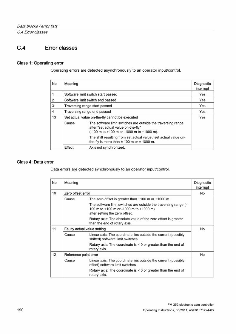
Data blocks / error lists C.4 Error classes
FM 352 electronic cam controller 190 Operating Instructions, 05/2011, A5E01071724-03
C.4 Error classes
Class 1: Operating error Operating errors are detected asynchronously to an operator input/control.
No. Meaning Diagnostic
interrupt 1 Software limit switch start passed Yes 2 Software limit switch end passed Yes 3 Traversing range start passed Yes 4 Traversing range end passed Yes
Set actual value on-the-fly cannot be executed Cause The software limit switches are outside the traversing range
after "set actual value on-the-fly" (-100 m to +100 m or -1000 m to +1000 m). The shift resulting from set actual value / set actual value on-the-fly is more than ± 100 m or ± 1000 m.
13
Effect Axis not synchronized.
Yes
Class 4: Data error Data errors are detected synchronously to an operator input/control.
No. Meaning Diagnostic
interrupt Zero offset error 10 Cause The zero offset is greater than ±100 m or ±1000 m.
The software limit switches are outside the traversing range (-100 m to +100 m or -1000 m to +1000 m) after setting the zero offset. Rotary axis: The absolute value of the zero offset is greater than the end of rotary axis.
No
Faulty actual value setting 11 Cause Linear axis: The coordinate lies outside the current (possibly
shifted) software limit switches. Rotary axis: The coordinate is < 0 or greater than the end of rotary axis.
No
Reference point error 12 Cause Linear axis: The coordinate lies outside the current (possibly
offset) software limit switches. Rotary axis: The coordinate is < 0 or greater than the end of rotary axis.
No
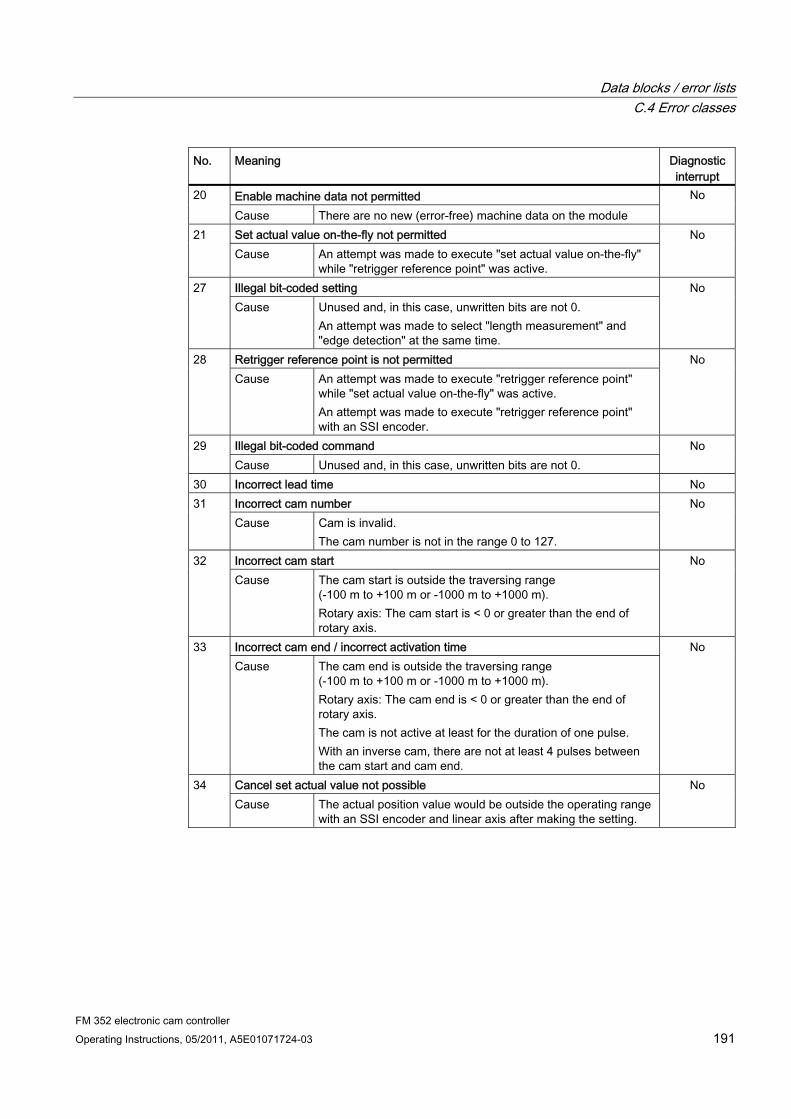
Data blocks / error lists C.4 Error classes
FM 352 electronic cam controller Operating Instructions, 05/2011, A5E01071724-03 191
No. Meaning Diagnostic interrupt
Enable machine data not permitted 20 Cause There are no new (error-free) machine data on the module
No
Set actual value on-the-fly not permitted 21 Cause An attempt was made to execute "set actual value on-the-fly"
while "retrigger reference point" was active.
No
Illegal bit-coded setting 27 Cause Unused and, in this case, unwritten bits are not 0.
An attempt was made to select "length measurement" and "edge detection" at the same time.
No
Retrigger reference point is not permitted 28 Cause An attempt was made to execute "retrigger reference point"
while "set actual value on-the-fly" was active. An attempt was made to execute "retrigger reference point" with an SSI encoder.
No
Illegal bit-coded command 29 Cause Unused and, in this case, unwritten bits are not 0.
No
30 Incorrect lead time No Incorrect cam number 31 Cause Cam is invalid.
The cam number is not in the range 0 to 127.
No
Incorrect cam start 32 Cause The cam start is outside the traversing range
(-100 m to +100 m or -1000 m to +1000 m). Rotary axis: The cam start is < 0 or greater than the end of rotary axis.
No
Incorrect cam end / incorrect activation time 33 Cause The cam end is outside the traversing range
(-100 m to +100 m or -1000 m to +1000 m). Rotary axis: The cam end is < 0 or greater than the end of rotary axis. The cam is not active at least for the duration of one pulse. With an inverse cam, there are not at least 4 pulses between the cam start and cam end.
No
Cancel set actual value not possible 34 Cause The actual position value would be outside the operating range
with an SSI encoder and linear axis after making the setting.
No

Data blocks / error lists C.4 Error classes
FM 352 electronic cam controller 192 Operating Instructions, 05/2011, A5E01071724-03
No. Meaning Diagnostic interrupt
Incorrect actual value specified by "set actual value" / "set actual value on-the-fly"
35
Cause The specified actual value is outside the permitted numeric range of ±100 m or ±1000 m. When this setting is applied, the software limit switches would be outside the traversing range (-100 m to +100 m or -1000 m to +1000 m). The offset derived from set actual value / set actual value on-the-fly would be more than ±100 m or ±1000 m.
No
Axis parameters not assigned 107 Cause There are no machine data on the axis.
There are no machine data activated on the axis.
No
Axis not synchronized 108 Cause One of the settings "set actual value" or "set actual value on-
the-fly" was initiated although the axis is not synchronized.
No
109 Cam processing running. No 110 Incorrect number of cams to be modified No
Class 5: Machine data error The diagnostic interrupt is only triggered if an error is detected in the system data block (SDB).
No. Meaning Diagnostic
interrupt Error in hardware interrupt setting 5 Cause You have attempted to select a hardware interrupt that the
module does not support.
Yes
Incorrect minimum edge distance 6 Cause You have entered a value <0 or >109 µm as the minimum edge
distance
Yes
Incorrect axis type 8 Cause You have specified neither 0 nor 1 as the axis type
Yes
Incorrect end of rotary axis 9 Cause The value for the end of rotary axis is outside the permitted
range of 1 to 109 µm or 1 to 108 µm (depending on the resolution).
Yes
Incorrect encoder type 10 Cause The value for the encoder type is outside the permitted range
of 1 to 10
Yes
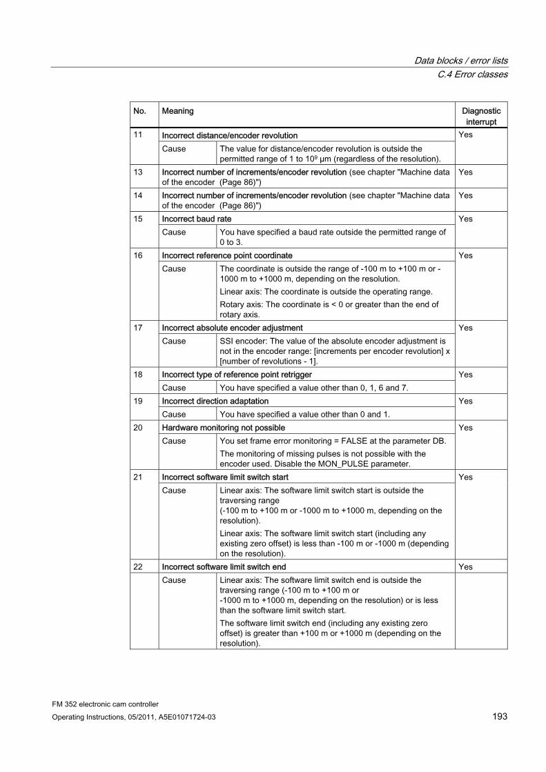
Data blocks / error lists C.4 Error classes
FM 352 electronic cam controller Operating Instructions, 05/2011, A5E01071724-03 193
No. Meaning Diagnostic interrupt
Incorrect distance/encoder revolution 11 Cause The value for distance/encoder revolution is outside the
permitted range of 1 to 109 µm (regardless of the resolution).
Yes
13 Incorrect number of increments/encoder revolution (see chapter "Machine data of the encoder (Page 86)")
Yes
14 Incorrect number of increments/encoder revolution (see chapter "Machine data of the encoder (Page 86)")
Yes
Incorrect baud rate 15 Cause You have specified a baud rate outside the permitted range of
0 to 3.
Yes
Incorrect reference point coordinate 16 Cause The coordinate is outside the range of -100 m to +100 m or -
1000 m to +1000 m, depending on the resolution. Linear axis: The coordinate is outside the operating range. Rotary axis: The coordinate is < 0 or greater than the end of rotary axis.
Yes
Incorrect absolute encoder adjustment 17 Cause SSI encoder: The value of the absolute encoder adjustment is
not in the encoder range: [increments per encoder revolution] x [number of revolutions - 1].
Yes
Incorrect type of reference point retrigger 18 Cause You have specified a value other than 0, 1, 6 and 7.
Yes
Incorrect direction adaptation 19 Cause You have specified a value other than 0 and 1.
Yes
Hardware monitoring not possible 20 Cause You set frame error monitoring = FALSE at the parameter DB.
The monitoring of missing pulses is not possible with the encoder used. Disable the MON_PULSE parameter.
Yes
Incorrect software limit switch start 21 Cause Linear axis: The software limit switch start is outside the
traversing range (-100 m to +100 m or -1000 m to +1000 m, depending on the resolution). Linear axis: The software limit switch start (including any existing zero offset) is less than -100 m or -1000 m (depending on the resolution).
Yes
22 Incorrect software limit switch end Yes Cause Linear axis: The software limit switch end is outside the
traversing range (-100 m to +100 m or -1000 m to +1000 m, depending on the resolution) or is less than the software limit switch start. The software limit switch end (including any existing zero offset) is greater than +100 m or +1000 m (depending on the resolution).
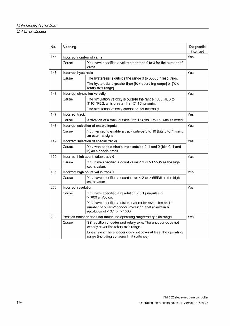
Data blocks / error lists C.4 Error classes
FM 352 electronic cam controller 194 Operating Instructions, 05/2011, A5E01071724-03
No. Meaning Diagnostic interrupt
Incorrect number of cams 144 Cause You have specified a value other than 0 to 3 for the number of
cams.
Yes
Incorrect hysteresis 145 Cause The hysteresis is outside the range 0 to 65535 * resolution.
The hysteresis is greater than [¼ x operating range] or {¼ x rotary axis range].
Yes
Incorrect simulation velocity 146 Cause The simulation velocity is outside the range 1000*RES to
3*107*RES, or is greater than 5* 108 µm/min. The simulation velocity cannot be set internally.
Yes
Incorrect track 147 Cause Activation of a track outside 0 to 15 (bits 0 to 15) was selected.
Yes
Incorrect selection of enable inputs 148 Cause You wanted to enable a track outside 3 to 10 (bits 0 to 7) using
an external signal.
Yes
Incorrect selection of special tracks 149 Cause You wanted to define a track outside 0, 1 and 2 (bits 0, 1 and
2) as a special track
Yes
Incorrect high count value track 0 150 Cause You have specified a count value < 2 or > 65535 as the high
count value.
Yes
Incorrect high count value track 1 151 Cause You have specified a count value < 2 or > 65535 as the high
count value.
Yes
Incorrect resolution 200 Cause You have specified a resolution < 0.1 µm/pulse or
>1000 µm/pulse. You have specified a distance/encoder revolution and a number of pulses/encoder revolution, that results in a resolution of < 0.1 or > 1000.
Yes
Position encoder does not match the operating range/rotary axis range 201 Cause SSI position encoder and rotary axis: The encoder does not
exactly cover the rotary axis range. Linear axis: The encoder does not cover at least the operating range (including software limit switches).
Yes
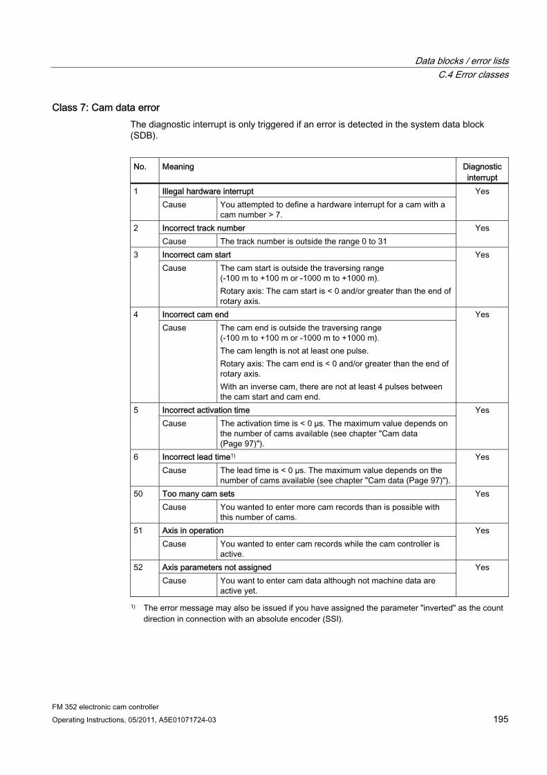
Data blocks / error lists C.4 Error classes
FM 352 electronic cam controller Operating Instructions, 05/2011, A5E01071724-03 195
Class 7: Cam data error The diagnostic interrupt is only triggered if an error is detected in the system data block (SDB).
No. Meaning Diagnostic
interrupt Illegal hardware interrupt 1 Cause You attempted to define a hardware interrupt for a cam with a
cam number > 7.
Yes
Incorrect track number 2 Cause The track number is outside the range 0 to 31
Yes
Incorrect cam start 3 Cause The cam start is outside the traversing range
(-100 m to +100 m or -1000 m to +1000 m). Rotary axis: The cam start is < 0 and/or greater than the end of rotary axis.
Yes
Incorrect cam end 4 Cause The cam end is outside the traversing range
(-100 m to +100 m or -1000 m to +1000 m). The cam length is not at least one pulse. Rotary axis: The cam end is < 0 and/or greater than the end of rotary axis. With an inverse cam, there are not at least 4 pulses between the cam start and cam end.
Yes
Incorrect activation time 5 Cause The activation time is < 0 µs. The maximum value depends on
the number of cams available (see chapter "Cam data (Page 97)").
Yes
Incorrect lead time1) 6 Cause The lead time is < 0 µs. The maximum value depends on the
number of cams available (see chapter "Cam data (Page 97)").
Yes
Too many cam sets 50 Cause You wanted to enter more cam records than is possible with
this number of cams.
Yes
Axis in operation 51 Cause You wanted to enter cam records while the cam controller is
active.
Yes
Axis parameters not assigned 52 Cause You want to enter cam data although not machine data are
active yet.
Yes
1) The error message may also be issued if you have assigned the parameter "inverted" as the count direction in connection with an absolute encoder (SSI).
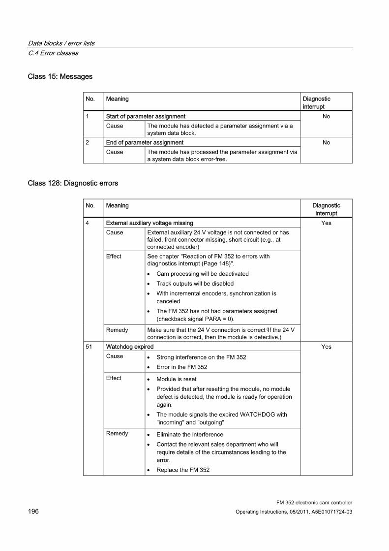
Data blocks / error lists C.4 Error classes
FM 352 electronic cam controller 196 Operating Instructions, 05/2011, A5E01071724-03
Class 15: Messages No. Meaning Diagnostic
interrupt Start of parameter assignment 1 Cause The module has detected a parameter assignment via a
system data block.
No
End of parameter assignment 2 Cause The module has processed the parameter assignment via
a system data block error-free.
No
Class 128: Diagnostic errors No. Meaning Diagnostic
interrupt External auxiliary voltage missing Cause External auxiliary 24 V voltage is not connected or has
failed, front connector missing, short circuit (e.g., at connected encoder)
Effect See chapter "Reaction of FM 352 to errors with diagnostics interrupt (Page 148)". Cam processing will be deactivated Track outputs will be disabled With incremental encoders, synchronization is
canceled The FM 352 has not had parameters assigned
(checkback signal PARA = 0).
4
Remedy Make sure that the 24 V connection is correct (If the 24 V connection is correct, then the module is defective.)
Yes
Watchdog expired Cause Strong interference on the FM 352
Error in the FM 352
Effect Module is reset Provided that after resetting the module, no module
defect is detected, the module is ready for operation again.
The module signals the expired WATCHDOG with "incoming" and "outgoing"
51
Remedy Eliminate the interference Contact the relevant sales department who will
require details of the circumstances leading to the error.
Replace the FM 352
Yes
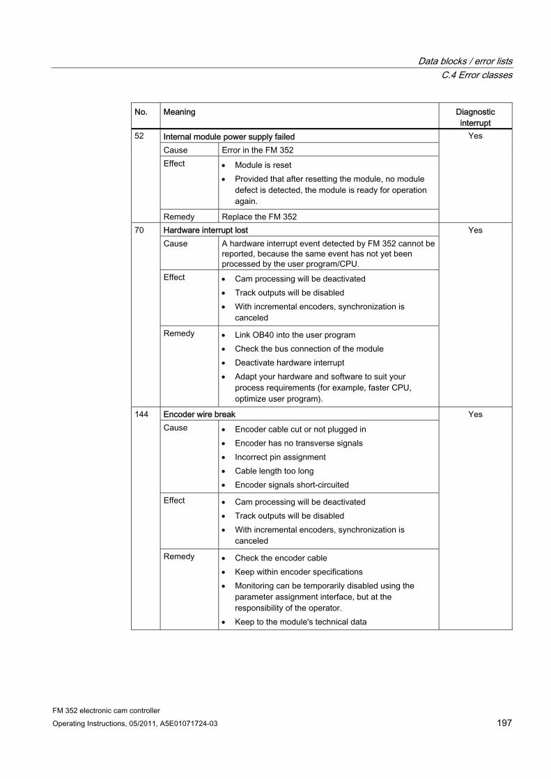
Data blocks / error lists C.4 Error classes
FM 352 electronic cam controller Operating Instructions, 05/2011, A5E01071724-03 197
No. Meaning Diagnostic interrupt
Internal module power supply failed Cause Error in the FM 352 Effect Module is reset
Provided that after resetting the module, no module defect is detected, the module is ready for operation again.
52
Remedy Replace the FM 352
Yes
Hardware interrupt lost Cause A hardware interrupt event detected by FM 352 cannot be
reported, because the same event has not yet been processed by the user program/CPU.
Effect Cam processing will be deactivated Track outputs will be disabled With incremental encoders, synchronization is
canceled
70
Remedy Link OB40 into the user program Check the bus connection of the module Deactivate hardware interrupt Adapt your hardware and software to suit your
process requirements (for example, faster CPU, optimize user program).
Yes
Encoder wire break Cause Encoder cable cut or not plugged in
Encoder has no transverse signals Incorrect pin assignment Cable length too long Encoder signals short-circuited
Effect Cam processing will be deactivated Track outputs will be disabled With incremental encoders, synchronization is
canceled
144
Remedy Check the encoder cable Keep within encoder specifications Monitoring can be temporarily disabled using the
parameter assignment interface, but at the responsibility of the operator.
Keep to the module's technical data
Yes

Data blocks / error lists C.4 Error classes
FM 352 electronic cam controller 198 Operating Instructions, 05/2011, A5E01071724-03
No. Meaning Diagnostic interrupt
Absolute encoder frame error Cause The frame traffic between FM 352 and the absolute
encoder (SSI) is incorrect or interrupted: Encoder cable cut or not plugged in Incorrect encoder type Encoder incorrectly set (programmable encoders) Frame length incorrectly specified Encoder returns incorrect values (encoder defective) Interference on measuring system cable Selected baud rate is too high
Effect Cam processing will be deactivated Track outputs will be disabled The last correct actual value remains unchanged until
the end of the next correct SSI transfer
145
Remedy Check the encoder cable Check the encoder Check the frame traffic between the encoder and
FM 352
Yes
Missing pulses of incremental encoder Cause Encoder monitoring has detected missing pulses
Number of increments per encoder revolution is incorrectly entered
Encoder defective: does not return the defined number of pulses
Bad or missing zero marker Interference on the encoder cable
Effect Cam processing will be deactivated Track outputs will be disabled Synchronization is canceled
146
Remedy Enter the correct number of increments/encoder revolution
Check the encoder and its cable Comply with shielding and grounding regulations Monitoring can be temporarily disabled using the
parameter assignment interface, but at the responsibility of the operator.
Yes

FM 352 electronic cam controller Operating Instructions, 05/2011, A5E01071724-03 199
Programming without SFB 52 and SFB 53 DD.1 Overview of the Programming without SFB 52 and SFB 53 section
If your CPU does not support the system blocks SFB 52 and SFB 53 with DPV1 functionality Then use the blocks from the program folder "FM 352,452 CAM V1" to program the FM 352.
You will find a description in this section.

Programming without SFB 52 and SFB 53 D.2 Basics of Programming an FM 352
FM 352 electronic cam controller 200 Operating Instructions, 05/2011, A5E01071724-03
D.2 Basics of Programming an FM 352
Task You can assign parameters, control, and commission the FM 352 module via a user program. To exchange data between the user program and module, you use the functions (FCs) and data blocks (DBs) described below.
Preparatory steps ● Open the FMx52LIB block library in SIMATIC Manager, then copy the required functions
(FCs) and block templates (UDTs) to the block folder of your project. If the block numbers are already being used, assign new numbers. The block names are entered unchanged in the symbol table of your S7 program.
– CAM_INIT (FC 0): This is required to initialize the channel DB following a module startup.
– CAM_CTRL (FC 1): This is required for data exchange with the module.
– CAM_DIAG (FC 2): This is required when you process detailed diagnostic information in the program or want to make this information available to an operator control and monitoring system.
– CAM_MSRM (FC 3): This can only be used with FM 452
– CAM_CHANTYPE (UDT1): This is required to generate a channel DB; used by the FCs CAM_INIT, CAM_CTRL and CAM_MSRM.
– CAM_DIAGTYPE (UDT2): This is required to generate a diagnostic DB; used by FC CAM_DIAG.
– CAM_P016TYPE (UDT3): This is required to generate a parameter DB with machine data and data for 16 cams; used by FC CAM_CTRL to write or read machine or cam data.
– CAM_P032TYPE (UDT4): Same as CAM_P016TYPE, however for 32 cams
– CAM_P064TYPE (UDT5): Same as CAM_P016TYPE, however for 64 cams
– CAM_P128TYPE (UDT6): Same as CAM_P016TYPE, however for 128 cams
● Create data blocks using the UDTs in the block folder of your S7 program. If you are using multiple modules, you require a separate set of data blocks for each module used.
● Enter the module address in the channel DB and, if applicable, in the diagnostic DB in MOD_ADDR.
● If your PG/PC is connected to a CPU, you can now download the FCs and DBs to the CPU.
Programming without SFB 52 and SFB 53 D.3 FC CAM_INIT (FC 0)
FM 352 electronic cam controller Operating Instructions, 05/2011, A5E01071724-03 201
D.3 FC CAM_INIT (FC 0)
Tasks FC CAM_INIT initializes the following data in the channel DB:
● The control signals
● The checkback signals
● The trigger, done and error bits of the jobs
● The function switches and their done and error bits
● Job management and the internal buffers for FC CAM_CTRL
Call The function must be executed after a startup (power on) of the module or CPU. You should therefore insert it, for example, in the restart OB (OB100) and the removal/insertion OB (OB83) or call it in the initialization phase of your user program. This ensures that your user program does not access obsolete data after a CPU or module restart.
Call parameters
Name Data type P-type Meaning DB_NO INT I Number of the channel DB
Return values This function does not return a return value.

Programming without SFB 52 and SFB 53 D.4 FC CAM_CTRL (FC 1)
FM 352 electronic cam controller 202 Operating Instructions, 05/2011, A5E01071724-03
D.4 FC CAM_CTRL (FC 1)
Tasks You can use FC CAM_CTRL to read operating data from the module, initialize the module, and control it during operation. For these tasks, you use the control signals, checkback signals, and write and read jobs.
On each call, the function performs the following actions:
● Read checkback signals:
FC CAM_CTRL reads all checkback signals from the module and enters them in the channel DB. The control signals and jobs are not executed until this task is completed, and thus the checkback signals reflect the module status prior to the block call.
● Write control signals:
The control signals written to the channel DB are transferred to the module. Enabling of cam processing, however, is delayed as long as the trigger for a "Set reference point" job or "Write cam data" job is set. The activation (or reactivation) of cam processing is delayed by this time.
● Execute job:
The next job is executed based on the trigger bits for jobs entered in the channel DB.
Call This function must be called cyclically.
Before you call the function, enter all the data in the channel DB that are required to execute the required functions.
Data used ● Channel DB:
The module address must be entered in the channel DB.
● Parameter DB:
If you want to write or read machine or cam data using jobs, you require a parameter DB whose number must be entered in the channel DB. The size of the parameter DB must be adequate for the number of cams.
Programming without SFB 52 and SFB 53 D.4 FC CAM_CTRL (FC 1)
FM 352 electronic cam controller Operating Instructions, 05/2011, A5E01071724-03 203
Jobs Data exchange with the module other than the control and checkback signals is handled by using jobs.
To start a job, set the corresponding trigger bit in the channel DB and provide the relevant data for write jobs. You then call FC CAM_CTRL to execute the job.
If you use the FM 352 centrally, a read job is executed immediately. If you use the FM 352 in a distributed system, a read job may take several cycles.
Due to the required confirmations from the module, a write job requires at least 3 calls (or OB cycles). If you use the FM 352 in a distributed system, a write job may take more than 3 calls.
You can send several jobs at the same time, if necessary, along with control signals. With the exception of the job for writing the function switches, the jobs are executed in the order of the trigger bits specified in the channel DB. Once a job has been completed, the trigger bit is canceled. The next time the block is called, the subsequent job is identified and executed.
For each job there is not only a trigger bit but also a done bit and an error bit. In their names, instead of the ending _EN (for "enable"), these jobs have the ending _D (for "done") or _ERR (for "error"). Done and error bits of the job should be set to 0 after they have been evaluated or before the job is started.
If you set the JOBRESET bit, all the done and error bits are reset before the pending jobs are processed. The JOBRESET bit is then reset to 0.
Function switches The function switches activate and deactivate the states of the module. A job for writing the function switches is only executed if changes were made to a switch setting. The setting of the function switch is latched after the job has been executed.
Length measurements and edge detection must not be activated at the same time. FC CAM_CTRL makes sure that when one of the function switches is activated, the other is deactivated. The length measurement function is activated if you enable both function switches at the same time (0 → 1).
Function switches and jobs can be used at the same time in one FC CAM_CTRL call.
As with the jobs, there are done bits with the ending _D and error bits with the ending _ERR for the function switches.
To be able to evaluate the done and error bits, you should set these bits to 0 when you change a function switch.
Startup Call FC CAM_INIT at the startup of the module or CPU (see chapter "FC CAM_INIT (FC 0) (Page 201)"). Among other things, this also resets resets the function switches.
FC CAM_CTRL acknowledges the module startup. During this time, RET_VAL and JOBBUSY = 1.
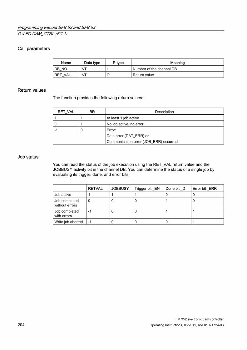
Programming without SFB 52 and SFB 53 D.4 FC CAM_CTRL (FC 1)
FM 352 electronic cam controller 204 Operating Instructions, 05/2011, A5E01071724-03
Call parameters
Name Data type P-type Meaning DB_NO INT I Number of the channel DB RET_VAL INT O Return value
Return values The function provides the following return values:
RET_VAL BR Description
1 1 At least 1 job active 0 1 No job active, no error -1 0 Error:
Data error (DAT_ERR) or Communication error (JOB_ERR) occurred
Job status You can read the status of the job execution using the RET_VAL return value and the JOBBUSY activity bit in the channel DB. You can determine the status of a single job by evaluating its trigger, done, and error bits.
RETVAL JOBBUSY Trigger bit _EN Done bit _D Error bit _ERR Job active 1 1 1 0 0 Job completed without errors
0 0 0 1 0
Job completed with errors
-1 0 0 1 1
Write job aborted -1 0 0 0 1
Programming without SFB 52 and SFB 53 D.4 FC CAM_CTRL (FC 1)
FM 352 electronic cam controller Operating Instructions, 05/2011, A5E01071724-03 205
Reaction to errors If faulty data were written by a write job, the module returns the message DATA_ERR = 1. If an error occurs during communication with the module for a write or read job, the cause of the error is entered in the JOB_ERR parameter in the channel DB.
● Error in a write job:
If an error occurs in a job, the trigger bit is canceled and the error bit (_ERR) and the done bit (_D) are set. The trigger bit is also canceled and the error bit (_ERR) is set for all write jobs still pending.
The pending read jobs will continue to be processed. JOB_ERR is reset again for each job.
● Error in a read job:
If an error occurs in a job, the trigger bit is canceled and the error bit (_ERR) and the done bit (_D) are set.
The read jobs still pending continue to be processed. JOB_ERR is reset again for each job.
For further error information, refer to the JOB_ERR and DATA_ERR parameters (see chapter "Possibilities for error evaluation (Page 145)").
Programming without SFB 52 and SFB 53 D.5 FC CAM_DIAG (FC 2)
FM 352 electronic cam controller 206 Operating Instructions, 05/2011, A5E01071724-03
D.5 FC CAM_DIAG (FC 2)
Tasks Use FC CAM_DIAG to read the data of the diagnostic buffer of the module and make these available for visualization on an operator control and monitoring system or for a programmed evaluation.
Call This function must be called cyclically. A further job in an interrupt OB is not permitted. At least 2 calls (cycles) are required to complete execution of this function..
The function reads the diagnostic buffer when a new entry in the diagnostic buffer is indicated by the checkback signal DIAG = 1. After the diagnostic buffer is read, DIAG is set to 0 by the module.
Data used ● Diagnostic DB:
The module address must be entered in the diagnostic DB. The last entry in the diagnostic buffer is entered in the DIAG[1] structure and the first entry in the DIAG[4] structure.
Jobs You can read the diagnostic buffer whether or not there is a new entry by setting the DIAGRD_EN trigger bit. After reading the diagnostic buffer, the trigger bit is set to 0.
Startup There is no startup processing associated with the function.
Call parameters
Name Data type P-type Meaning DB_NO INT I Number of the diagnostic DB RET_VAL INT O Return value
Programming without SFB 52 and SFB 53 D.5 FC CAM_DIAG (FC 2)
FM 352 electronic cam controller Operating Instructions, 05/2011, A5E01071724-03 207
Return values The function returns the following return values:
RET_VAL BR Description
1 1 Job active 0 1 No job active, no error -1 0 Error
Reaction to errors The cause of a job error can be read in the JOB_ERR parameter of the diagnostic DB (see chapter "Possibilities for error evaluation (Page 145)").
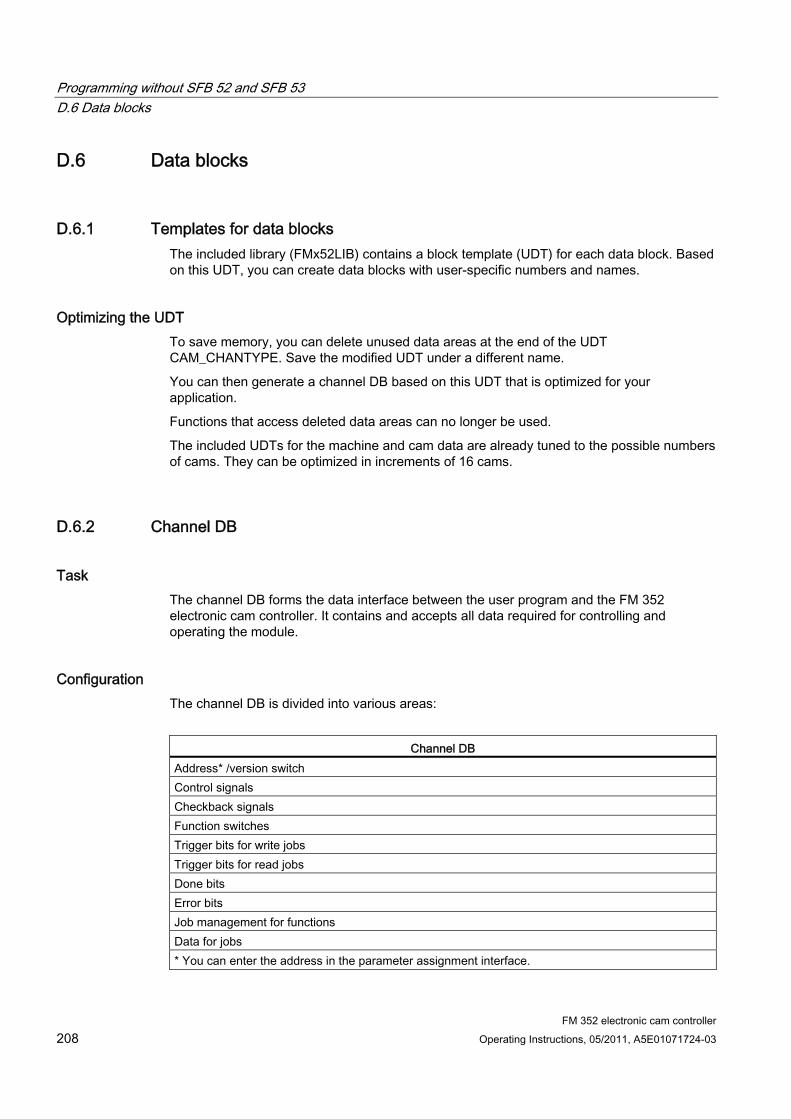
Programming without SFB 52 and SFB 53 D.6 Data blocks
FM 352 electronic cam controller 208 Operating Instructions, 05/2011, A5E01071724-03
D.6 Data blocks
D.6.1 Templates for data blocks The included library (FMx52LIB) contains a block template (UDT) for each data block. Based on this UDT, you can create data blocks with user-specific numbers and names.
Optimizing the UDT To save memory, you can delete unused data areas at the end of the UDT CAM_CHANTYPE. Save the modified UDT under a different name.
You can then generate a channel DB based on this UDT that is optimized for your application.
Functions that access deleted data areas can no longer be used.
The included UDTs for the machine and cam data are already tuned to the possible numbers of cams. They can be optimized in increments of 16 cams.
D.6.2 Channel DB
Task The channel DB forms the data interface between the user program and the FM 352 electronic cam controller. It contains and accepts all data required for controlling and operating the module.
Configuration The channel DB is divided into various areas:
Channel DB
Address* /version switch Control signals Checkback signals Function switches Trigger bits for write jobs Trigger bits for read jobs Done bits Error bits Job management for functions Data for jobs * You can enter the address in the parameter assignment interface.
Programming without SFB 52 and SFB 53 D.6 Data blocks
FM 352 electronic cam controller Operating Instructions, 05/2011, A5E01071724-03 209
D.6.3 Diagnostics DB
Task The diagnostic DB provides the data storage for FC CAM_DIAG and contains the diagnostic buffer of the module prepared by this function.
Configuration
Diagnostic DB Module address Internal data Job status Trigger bit Prepared diagnostic buffer
Programming without SFB 52 and SFB 53 D.6 Data blocks
FM 352 electronic cam controller 210 Operating Instructions, 05/2011, A5E01071724-03
D.6.4 Parameter DB
Task All machine and cam data are stored in the parameter DB. These parameters can be modified by the user program or by an operator control and monitoring system. The modified data can be imported to the parameter assignment interface and displayed there. You can export data displayed in the parameter assignment interface to a parameter DB.
A module may contain several parameter data sets (for example, for various recipes) that can be selected from the program.
Configuration
Parameter DB CAM_P016TYPE (UDT3) Machine data Cam data of cams 0 to 15 CAM_P032TYPE (UDT4) Machine data Cam data of cams 0 to 31 CAM_P064TYPE (UDT5) Machine data Cam data of cams 0 to 63 CAM_P0128TYPE (UDT6) Machine data Cam data of cams 0 to 127
Programming without SFB 52 and SFB 53 D.7 Interrupts
FM 352 electronic cam controller Operating Instructions, 05/2011, A5E01071724-03 211
D.7 Interrupts
Interrupt processing The FM 352 can trigger hardware and diagnostic interrupts. You process those interrupts in an interrupt OB. If an interrupt is triggered and the corresponding OB is not loaded, the CPU goes to STOP mode (refer to the Programming with STEP 7 Manual).
You can enable interrupt processing in the following stages:
1. Global interrupt enable for the entire module
– Select the module in HW Config
Select Edit > Object Properties > Basic Parameters, then enable the diagnostic and/or hardware interrupt.
– Select the OB number for the hardware interrupt using Edit > Object Properties > Addresses.
– Save and compile the hardware configuration.
– Download the hardware configuration to the CPU.
2. Enable the hardware interrupt events in the machine data.
3. Assign the hardware interrupts in the cam data for cams 0 to 7.
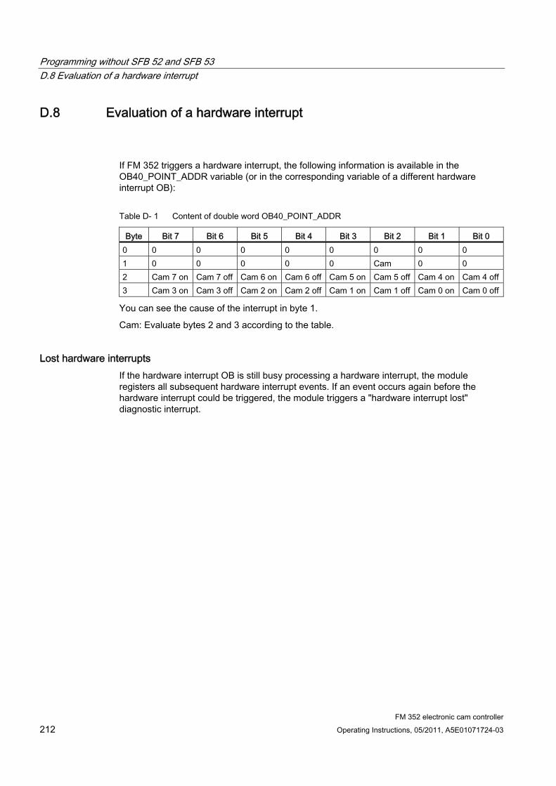
Programming without SFB 52 and SFB 53 D.8 Evaluation of a hardware interrupt
FM 352 electronic cam controller 212 Operating Instructions, 05/2011, A5E01071724-03
D.8 Evaluation of a hardware interrupt
If FM 352 triggers a hardware interrupt, the following information is available in the OB40_POINT_ADDR variable (or in the corresponding variable of a different hardware interrupt OB):
Table D- 1 Content of double word OB40_POINT_ADDR
Byte Bit 7 Bit 6 Bit 5 Bit 4 Bit 3 Bit 2 Bit 1 Bit 0 0 0 0 0 0 0 0 0 0 1 0 0 0 0 0 Cam 0 0 2 Cam 7 on Cam 7 off Cam 6 on Cam 6 off Cam 5 on Cam 5 off Cam 4 on Cam 4 off3 Cam 3 on Cam 3 off Cam 2 on Cam 2 off Cam 1 on Cam 1 off Cam 0 on Cam 0 off
You can see the cause of the interrupt in byte 1.
Cam: Evaluate bytes 2 and 3 according to the table.
Lost hardware interrupts If the hardware interrupt OB is still busy processing a hardware interrupt, the module registers all subsequent hardware interrupt events. If an event occurs again before the hardware interrupt could be triggered, the module triggers a "hardware interrupt lost" diagnostic interrupt.
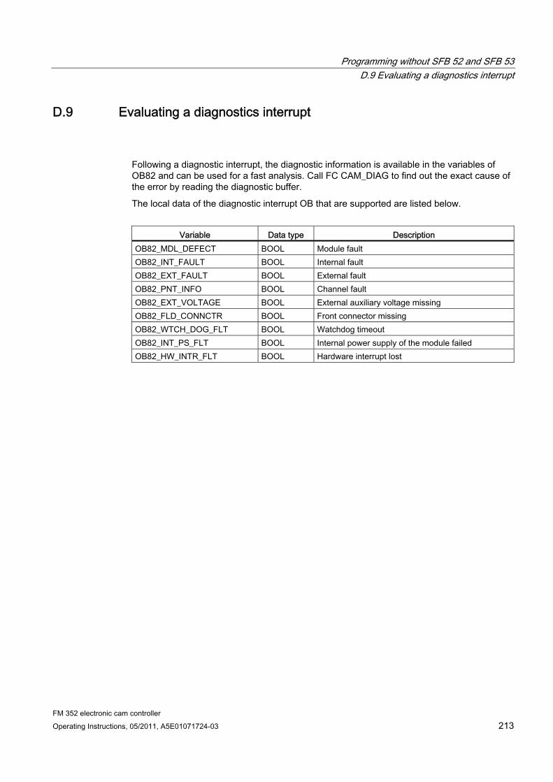
Programming without SFB 52 and SFB 53 D.9 Evaluating a diagnostics interrupt
FM 352 electronic cam controller Operating Instructions, 05/2011, A5E01071724-03 213
D.9 Evaluating a diagnostics interrupt
Following a diagnostic interrupt, the diagnostic information is available in the variables of OB82 and can be used for a fast analysis. Call FC CAM_DIAG to find out the exact cause of the error by reading the diagnostic buffer.
The local data of the diagnostic interrupt OB that are supported are listed below.
Variable Data type Description
OB82_MDL_DEFECT BOOL Module fault OB82_INT_FAULT BOOL Internal fault OB82_EXT_FAULT BOOL External fault OB82_PNT_INFO BOOL Channel fault OB82_EXT_VOLTAGE BOOL External auxiliary voltage missing OB82_FLD_CONNCTR BOOL Front connector missing OB82_WTCH_DOG_FLT BOOL Watchdog timeout OB82_INT_PS_FLT BOOL Internal power supply of the module failed OB82_HW_INTR_FLT BOOL Hardware interrupt lost
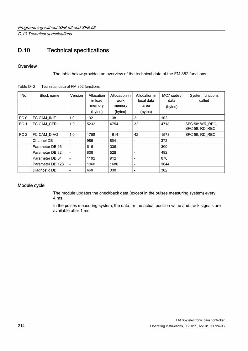
Programming without SFB 52 and SFB 53 D.10 Technical specifications
FM 352 electronic cam controller 214 Operating Instructions, 05/2011, A5E01071724-03
D.10 Technical specifications
Overview The table below provides an overview of the technical data of the FM 352 functions.
Table D- 2 Technical data of FM 352 functions
No. Block name Version Allocation in load
memory (bytes)
Allocation in work
memory (bytes)
Allocation in local data
area (bytes)
MC7 code / data
(bytes)
System functions called
FC 0 FC CAM_INIT 1.0 192 138 2 102 FC 1 FC CAM_CTRL 1.0 5232 4754 32 4718 SFC 58: WR_REC,
SFC 59: RD_REC FC 2 FC CAM_DIAG 1.0 1758 1614 42 1578 SFC 59: RD_REC Channel DB - 986 804 - 372 Parameter DB 16
Parameter DB 32 Parameter DB 64 Parameter DB 128
- - - -
616 808 1192 1960
336 528 912 1680
- - - -
300 492 876 1644
Diagnostic DB - 460 338 - 302
Module cycle The module updates the checkback data (except in the pulses measuring system) every 4 ms.
In the pulses measuring system, the data for the actual position value and track signals are available after 1 ms.
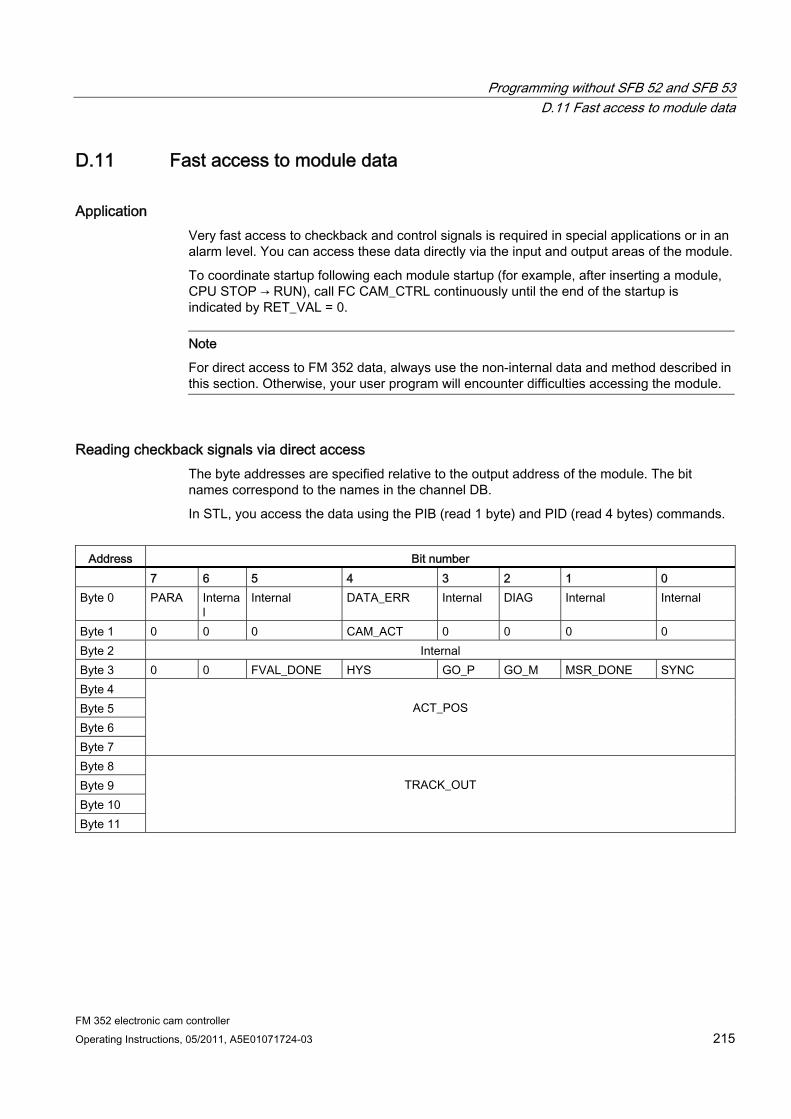
Programming without SFB 52 and SFB 53 D.11 Fast access to module data
FM 352 electronic cam controller Operating Instructions, 05/2011, A5E01071724-03 215
D.11 Fast access to module data
Application Very fast access to checkback and control signals is required in special applications or in an alarm level. You can access these data directly via the input and output areas of the module.
To coordinate startup following each module startup (for example, after inserting a module, CPU STOP → RUN), call FC CAM_CTRL continuously until the end of the startup is indicated by RET_VAL = 0.
Note
For direct access to FM 352 data, always use the non-internal data and method described in this section. Otherwise, your user program will encounter difficulties accessing the module.
Reading checkback signals via direct access The byte addresses are specified relative to the output address of the module. The bit names correspond to the names in the channel DB.
In STL, you access the data using the PIB (read 1 byte) and PID (read 4 bytes) commands.
Address Bit number
7 6 5 4 3 2 1 0 Byte 0 PARA Interna
l Internal DATA_ERR Internal DIAG Internal Internal
Byte 1 0 0 0 CAM_ACT 0 0 0 0 Byte 2 Internal Byte 3 0 0 FVAL_DONE HYS GO_P GO_M MSR_DONE SYNC Byte 4 Byte 5 Byte 6 Byte 7
ACT_POS
Byte 8 Byte 9 Byte 10 Byte 11
TRACK_OUT
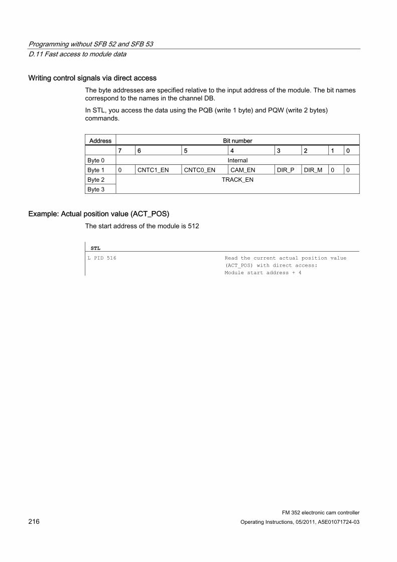
Programming without SFB 52 and SFB 53 D.11 Fast access to module data
FM 352 electronic cam controller 216 Operating Instructions, 05/2011, A5E01071724-03
Writing control signals via direct access The byte addresses are specified relative to the input address of the module. The bit names correspond to the names in the channel DB.
In STL, you access the data using the PQB (write 1 byte) and PQW (write 2 bytes) commands.
Address Bit number
7 6 5 4 3 2 1 0 Byte 0 Internal Byte 1 0 CNTC1_EN CNTC0_EN CAM_EN DIR_P DIR_M 0 0 Byte 2 Byte 3
TRACK_EN
Example: Actual position value (ACT_POS) The start address of the module is 512
STL
L PID 516 Read the current actual position value (ACT_POS) with direct access: Module start address + 4

Programming without SFB 52 and SFB 53 D.12 Parameter transfer routes
FM 352 electronic cam controller Operating Instructions, 05/2011, A5E01071724-03 217
D.12 Parameter transfer routes
Transmission paths The term parameter refers to the following machine and cam data.
Figure D-1 Parameter transmission paths
1 Save the parameters in the parameter assignment interface. 2 Save and compile the HW configuration and download it to the CPU. 3 The CPU writes the parameters to the module during system parameter assignment. 4 Upload the module parameters to the PG by selecting the "PLC > Upload to PG" command. 5 Download the parameters from the parameter assignment interface to the module with the
"PLC > Download" command. 6 Write parameters to the module using jobs in the user program. 7 Read parameters from the module using jobs in the user program. 8 Save parameters from the user program to the online DB. 9 Read in parameters from the online DB to the user program. 10 Export parameters from the parameter assignment interface to the DB (offline or online DB);
an online DB must then be downloaded to the CPU. 11 Import parameters from an online or offline DB into the parameter assignment interface.
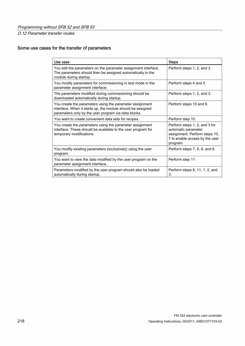
Programming without SFB 52 and SFB 53 D.12 Parameter transfer routes
FM 352 electronic cam controller 218 Operating Instructions, 05/2011, A5E01071724-03
Some use cases for the transfer of parameters Use case Steps You edit the parameters on the parameter assignment interface. The parameters should then be assigned automatically to the module during startup.
Perform steps 1, 2, and 3.
You modify parameters for commissioning in test mode in the parameter assignment interface:
Perform steps 4 and 5
The parameters modified during commissioning should be downloaded automatically during startup.
Perform steps 1, 2, and 3.
You create the parameters using the parameter assignment interface. When it starts up, the module should be assigned parameters only by the user program via data blocks.
Perform steps 10 and 6.
You want to create convenient data sets for recipes. Perform step 10. You create the parameters using the parameter assignment interface. These should be available to the user program for temporary modifications.
Perform steps 1, 2, and 3 for automatic parameter assignment. Perform steps 10, 7 to enable access by the user program.
You modify existing parameters (exclusively) using the user program.
Perform steps 7, 9, 8, and 6.
You want to view the data modified by the user program on the parameter assignment interface.
Perform step 11.
Parameters modified by the user program should also be loaded automatically during startup.
Perform steps 6, 11, 1, 2, and 3.
FM 352 electronic cam controller Operating Instructions, 05/2011, A5E01071724-03 219
Index
A Absolute encoder, 76, 141
Data transfer, 141 Frame run time, 143 Monoflop time, 143 Pulse evaluation, 141 Reaction times, 143
Absolute encoder (SSI), 78 Absolute encoder adjustment, 69
Alternative, 85 Data in the channel DB, 83 Definition, 82 Determining, 82 Example, 84
Activating the cam Condition, 16
Activation of track outputs, 94 Activation time, 100 Actual value change, 103 Addresses, 177 adjustment
Dynamic, 24 Ambient temperatures, 27 Applying glue tracks, 12 Assigning parameters, 63
Requirements, 37 Asymmetrical output signals, 138 AVAL, 105 AVAL_EN, 105 Axis synchronization, 64 Axis type, 75 Axis type, 75 AXIS_TYPE, 75
B BAUD RATE, 89 Block library, 40, 58, 200, 217 Block templates, 40, 58, 200, 217 Brake cam track, 21, 95
C C_CBEGIN, 114 C_CEND, 114 C_EFFDIR, 114 C_LTIME, 114 C_QTY, 94, 114 Cable length
Maximum, 89 Cam
Direction-based, 16 Inverse, 17 Switching characteristics, 97
Cam controller, 14 Cam cycle time, 94 Cam data, 67, 102
Activation time, 100 Cam end, 99, 100 Cam start, 99, 100 Cam valid, 98 Definition, 97 Hardware interrupt on activation, 98 Hardware interrupt on deactivation, 98 Lead time, 101 Negative effective direction (minus), 98 Position-based cam, 98 Positive effective direction (plus), 98 Reading, 72 Time-based cam, 98 Track number, 98 Writing, 71
Cam data error, 195 Cam data in the parameter DB, 98 Cam end, 99 Cam start, 99 Cam tracks, 18 CAM_CTRL
Parameters, 43 CAM_DIAG
Parameters, 47 CAM_END, 112 CAM_NO, 112, 114 CAM_OFF, 114 CAM_START, 112 CAM_TYPE, 98 Cams
Directional reversal, 23
Index
FM 352 electronic cam controller 220 Operating Instructions, 05/2011, A5E01071724-03
CAMVALID, 98 Cancel set actual value, 104
AVALREM_EN, 106 Canceling the setting
Cancel set actual value, 106 CBEGIN, 99, 100, 115 CEND, 99, 100, 115 CH01CAM_EN, 112 CH16CAM_EN, 114 Change cam edges, 112
Canceling, 113 Data used in the channel DB, 112 Definition, 112 Effects, 113 Requirement, 112 Sequence, 112
Channel DB, 49, 58, 177, 208, 217 Configuration, 49, 58, 208, 217 Preparing, 65 Task, 49, 58, 208, 217
Checkback signal, 177 Checkback signals
Reading, 56, 58, 215, 217 CNT_DIR, 89 CNT_LIM0, 95 CNT_LIM1, 95 Commissioning, 63 Components
Electronic cam control, 13 Configuration
Channel DB, 58, 217 Connecting cables, 34 Control signals, 177
Transferring, 58, 217 Writing, 57, 58, 216, 217
Count direction, 89 Counter cam track, 20, 24, 95
High count value, 95 CPU
Startup, 45, 58, 203, 217 Current consumption, 27
D Data block
Channel, 177 Diagnostics, 187 Parameters, 185
Data check, 115 by the module, 115
Data element for set actual value job, 182 Data element for set actual value on-the-fly job, 182
Data element for set reference point job, 182 Data element for zero offset job, 182 Data error, 190 Data for change cam edges job, 183 Data for fast cam parameter change job, 183 Data for length measurement/edge detection job, 183 Data for read cam and track data job, 183 Data for read count values job, 183 Data for read encoder data job, 183 Data for read position and track data job, 183 DB diagnostics
Entry structure, 188 Error Messages, 188
DC load power supply, 32 Deactivating the cam
Condition, 16 Default system of units, 74 Derivative-action time, 24 Determining a coordinate
Zero offset, 107 Diagnostic DB, 50, 58, 209, 217
Configuration, 50, 58, 187, 209, 217 Preparing, 65 Task, 50, 58, 209, 217
Diagnostic errors, 196 Diagnostic interrupt
Evaluating, 213, 217 Incoming, 148 Outgoing, 148 Overview, 147 Reaction of FM 352, 148
Diagnostic Interrupt Evaluating, 58
Diagnostic interrupts, 147 Digital inputs, 33 Digital outputs, 32, 33 Direct access to checkback signals, 56, 58, 215, 217 Direction adaptation, 69 Direction detection, 16 Direction of motion, 16 Directional reversal
at a cam, 23 Direction-based cams, 16 DIS_CHECK, 114 DISP_REV, 87 Distance per encoder revolution, 69, 87 Done bits for function switches, 180 Done bits for read jobs, 181 Done bits for write jobs, 180 Downloading blocks to the CPU, 65 Dynamic adjustment, 24, 102
Index
FM 352 electronic cam controller Operating Instructions, 05/2011, A5E01071724-03 221
E Edge distance
Deactivating, 115 EDGEDIST, 81 EFFDIR_M, 98, 115 EFFDIR_P, 98, 114 Effective direction, 15, 97, 98 Electronic cam controller, 13 EN_IN_I3, 95 Enable input, 95 Enabling
Machine data, 68 ENC_ADJ, 82 ENC_TYPE, 86 Encoder
Mechanical adjustment, 85 Multiturn, 141 Single-turn, 141
Encoder interface, 30 Encoder range, 78 Encoder supply, 32 Encoder type, 69, 86 Encoder types
supported by FM 352, 169 Encoders, 31
Total number of steps, 88 End of rotary axis, 69, 76 ENDROTAX, 76 Error bits for function switches, 181 Error bits for read jobs, 182 Error bits for write jobs, 181 Error evaluation, 145 Error LED, 146 Error Messages
DB diagnostics, 188 Examples
Using, 153 Execution times, 58, 217 External enable, 19, 95
F Fast access to module data, 58, 215, 217 Fast cam parameter change
Canceling, 115 Data check, 115 Data used in the channel DB, 114 Definition, 114 Effects, 115 Requirement, 114 Steps, 114
FB CAM_CTRL Call, 43 Data used, 43 Error behavior, 46 Return values, 45 Tasks, 43
FB CAM_DIAG Call, 47 Data used, 47 Error behavior, 48 Return values, 48 Tasks, 47
FC 0 FC CAM_INIT, 58, 201, 217
FC 1 FC CAM_CTRL, 202, 217
FC 2 FC CAM_DIAG, 206, 217
FC CAM_CTRL, 202, 217 Call, 202, 217 Call parameters, 204, 217 Data used, 202, 217 Error behavior, 205, 217 Return values, 204, 217 Tasks, 202, 217
FC CAM_DIAG, 206, 217 Call, 206, 217 Data used, 206, 217 Error behavior, 207, 217 Parameters, 206, 217 Return values, 207, 217 Tasks, 206, 217
FC CAM_INIT, 58, 201, 217 Call, 42, 58, 201, 217 Parameters, 42, 58, 201, 217 Return values, 42, 58, 201, 217 Tasks, 42, 58, 201, 217
Fields of application FM 352, 12
Flat gain, 139, 144 FM 352
Commissioning, 61 Fields of application, 12 Programming, removing, 28 Startup,
Frame error, 90 Frame length, 86 Front connector, 32
Assignment, 32
Index
FM 352 electronic cam controller 222 Operating Instructions, 05/2011, A5E01071724-03
Function switches, 44, 58, 178, 203, 217 Functions, 40, 58, 200, 217
Execution times, 58, 217 Technical specifications, 58, 214, 217
FVAL, 105 FVAL_DONE, 105 FVAL_EN, 105
G Getting prepared for programming, 64
H Hardware installation, 62 Hardware interrupt, 96
Evaluating, 58, 212, 217 Lost, 53, 58, 212, 217
High count value of counter cam track, 95 Horizontal installation, 27 HYS, 79 Hysteresis, 79
Position-based cam, 79 Time-based cam, 80
Hysteresis range, 22, 79 Rules, 22, 79
I INC_REV, 87 Increment, 138 Incremental encoder, 76
Missing pulses, 90 Reaction times, 139 Signal shapes, 138
Increments per encoder revolution, 69 Initiator, 76, 140
Signal evaluation, 140 Installation, 37
Functions, 37 Parameter assignment interface, 37
Integrating blocks, 65 Interrupt enable
Cam data for, 96 Definition, 96 Machine data in the parameter DB, 96
Interrupt processing, 52, 58, 211, 217
J Job
execute, 58 Executing, 217
Job management for FB CAM_CTRL, 182 Job status, 45, 58, 204, 217 Jobs, 44, 58, 203, 217
L Lead time, 101 Limit switches, 62
safety-relevant, 62 Linear axis, 75, 76 Linear scale, 88 Listen in, 86, 142
Wiring, 142 Load power supply, 32 Loss of synchronization, 109 LTIME, 101, 115
M Machine and cam data
Sequence when writing, 67 Machine data, 67
Absolute encoder adjustment, 82 Activation of track outputs, 94 Axis type, 75 Baud rate, 89 Count direction, 89 Distance per encoder revolution, 87 Enable input, 95 Enabling, 68 Encoder type, 86 End of rotary axis, 76 Frame length, 86 High count value of counter cam track, 95 Hysteresis, 79 Increments per encoder revolution, 87 Minimum edge interval, 81 Monitoring, 90 Number of encoder revolutions, 88 Reading, 70 Reference point coordinate, 76 Simulation velocity, 81 Software limit switch end, 78 Software limit switch start, 78 Special tracks, 95 Type of reference point retriggering, 77 Writing, 68, 70
Index
FM 352 electronic cam controller Operating Instructions, 05/2011, A5E01071724-03 223
Machine data error, 192 Machine data of the encoder
Data in the parameter DB, 86 Definition, 86
Maximum cable length, 89 MD_EN, 70 MDRD_EN, 70 MDWR_EN, 70 Messages, 196 Minimum edge interval, 81 Missing pulses
Incremental encoder, 90 Module cycle, 55, 58, 214, 217 Module data
Fast access, 215, 217 High-speed access, 58
MON_FRAME, 90 MON_PULSE, 90 MON_WIRE, 90 Monitoring, 90 Motor, 13 Mounting position, 27 Multiturn encoder, 141
N NO_REV, 88 Non-isolation, 35 Number of cams, 69, 94 Number of revolutions, 69
O OB40_POINT_ADDR
Content, 53, 58, 212, 217 On period, 16 Operating error, 190 Optimizing
UDT, 58, 217 Output signal
Asymmetrical, 138 Symmetrical, 138
P Packaging unit, 12 Parameter assignment
Position-/time-based cams, 15 Parameter assignment interface, 37, 63
installing, 37 Parameter DB, 185
Areas, 51, 58, 210, 217 Configuration, 51, 58, 210, 217 Task, 51, 58, 210, 217
Parameters CAM_CTRL, 43 CAM_DIAG, 47
Path length, 16 PI_SW_OFF, 98 PI_SW_ON, 98 Position of the front connector, 32 Position-based cam
Definition, 15 with assigned hysteresis, 79
Power drive, 13 Press control, 12 Programming
FM 352, 58, 217
R Rail, 27 Rail mounting position, 27 Reading
Cam data, 72 Reference point coordinate, 69, 76 REFPT, 76, 110 REFPT_EN, 110 Relative address, 184 Requirements
Assigning parameters, 37 Resolution, 91
Calculation, 91 Definition, 91 Example, 92 Range of values, 91
RETR_TYPE, 77 Retrigger reference point, 77 Rotary axis, 75, 76
Index
FM 352 electronic cam controller 224 Operating Instructions, 05/2011, A5E01071724-03
S Safety rule, 29 Safety rules, 27 Safety system, 13 Safety-relevant limit switches, 62 Scope of the manual, 7 Sequence when writing
Machine and cam data, 67 Set actual value, 104, 106
Data in the channel DB, 105 Effect, 105 Requirements, 104 Steps, 104
Set actual value on-the-fly, 104 Data in the channel DB, 105 Requirements, 104 Steps, 104
Set reference point, 110 Data used in the channel DB, 110 Definition, 110 Effects, 111 Requirement, 110 Special features of absolute encoders, 111 Steps, 110
Setting Cancel set actual value, 104 Change cam edges, 112 Set actual value, 104 Set actual value on-the-fly, 104 Set reference point, 110 Zero offset, 107
Setting up a project, 62 Shield connection element, 31 SIM_SPD, 81 Simulation velocity, 81 Single-turn encoder, 141 Slot, 27 Software limit switch, 69 Software limit switch end, 78 Software limit switch start, 78 SPEC_TRC0, 95 SPEC_TRC1, 95 SPEC_TRC2, 95 Special track
Requirements, 20 Special tracks, 20, 95 SSW_END, 78 SSW_STRT, 78 Status and error displays, 146 Sub D socket, 30 Switching characteristics, 64
of time-based cams, 103
Symmetrical output signals, 138 SYNC, 110 Synchronization
loss of, 109 System of units
in the parameter DB, 73 Selecting, 73
T Technical specifications, 58, 214, 217 Terminal assignment of the front connector, 32 Testing, 63 Time-based cam
Definition, 15 Effect of settings, 103 Switching, 103 Switching characteristics, 97, 103 with assigned hysteresis, 80 with hysteresis, 80
Tools, 27 Total number of encoder steps, 88 Track 3
External enable, 19 Track data, 94 Track enable
enabling, 18 Track outputs
Activation, 94 Track result, 18
Example, 18 Track signal
setting, 19 TRACK_NO, 98 TRACK_OUT, 94 Traversing range, 78
Dependency, 92 Resolution, 92
Trigger bits for read jobs, 179 Trigger bits for write jobs, 178 Type of reference point retriggering, 69, 77
Index
FM 352 electronic cam controller Operating Instructions, 05/2011, A5E01071724-03 225
U UDT, 58, 217
Optimizing, 58, 217 Use case
typical, 11
V Velocity
Dependency on the resolution, 93 Version switch, 177
W Wire break, 90 Wire end ferrules, 34 Wiring encoders, 31 Working range, 78 Writing
Cam data, 71 Machine data, 68
Z Zero offset
Canceling, 109 Data used in the channel DB, 108 Definition, 107 Effects on a linear axis, 108 on a rotary axis, 109 Steps, 107 ZOFF_EN, 107

Index
FM 352 electronic cam controller 226 Operating Instructions, 05/2011, A5E01071724-03


![352 Israel Law Reports [2006] (2) IsrLR 352 HCJ 8276/05 Adalah](https://img.pdfslide.us/doc/110x75/588496851a28abcd198c3f80/352-israel-law-reports-2006-2-isrlr-352-hcj-827605-adalah-.jpg)