Embed Size (px)
Citation preview

74000 E16 5w 5v 12v
74001 E16 6w 5v
74002 E16 6w 12v
74003 E16 5w 3.3v 5v
74010 E16 12w 5v 12v
74014 E16 12w 24v 24v
74015 E16 12w 5v 15v 24v
74020 EL19 18w 5v 12v
74021 EL19 18w 5v 12v
74023 EL19 16w 3.3v 5v 12v 18v 30v
74030 E25 30w 5v 12v 12v
74032 E25 35w 24v
74040 ETD29 60w 5v 12v 5v 12v
74043 ERL28 60w 3.3v 5v 12v 18v 30v
74050 ETD34 90w 5v 12v 5v 12v
74060 ETD39 140w 5v 12v 5v 12v
74070 ETD44 180w 5v 12v 5v 12v
74080 EF20 24w 12v 12v
74081 EF20 20w 3.3v 5v 12v
74082 EF20 20w 5v 5v
74090 E16 1.5w 5v
74091 E16 1.5w 12v
74092 E16 3.1w 5v
74093 E16 3.1w 12v
74094 E16 9w 5v
74095 E16 9w 12v
Watts
MYRRA
Part N°
Max.
Output
Power
Vdc nominal voltage
CORE
SIZE
Outputs
Note : “5 volts” outputs can generally be used for 3.3 to 6volts; “12 volts” outputs can be used for 9 to 16volts.
See detailed characteristics.
FLYBACK TRANSFORMERS RANGE for switch mode power supplies
PO
WE
R F
ER
RIT
E T
RA
NS
FOR
ME
RS
HIG
H F
RE
QU
EN
CY
FE
RR
ITE
26

PO
WE
R F
ER
RIT
E T
RA
NS
FOR
ME
RS
HIG
H F
RE
QU
EN
CY
FE
RR
ITE
27
TRANSFORMER / CONTROL CIRCUITS CROSS-REFERENCE LIST
Transformer
Reference
IC
Manufacturer
Series &
References
74090
74091
74092
74093
74094
74095
No aux. Winding PITNY Series
LNK XT Series
74000
74001
74002
74003
74004
74005
74010
74014
74015
74020
74021
74023
74080
74081
74082
74087
74088
74089
74030
74032
74040
74043
74050
74060
74070
With aux. Winding
ONSEMINCP 1014
NCP 3065
etc.
PITOP Series
LNK Series
NXP
TEA1530
TEA1351
TEA3065
etc.
ST Viper Series
FAIRCHILD
FAN102
FAN400
FSEZ130
FSEZ1213
etc.
ON Bright
OB2535
OB2212
OB2361
etc.

74090 1.5 w Pri 10 – 9 228 85 - 265Vrms 0.28 Apeak 6000µH
S1 5 – 2 16 3.3 – 6 Vdc 0.4 Adc
74091 1.5 w Pri 10 – 9 228 85 - 265Vrms 0.28 Apeak 6000µH
S1 5 – 2 28 7.5 – 15 Vdc 0.2 Adc
Frequency
Windings
Pin 3 Removed PCB Drilling Diameter = 1.1mmBottom View (Pin side)
0V +S1 DRAIN+E
• Primary / Secondary Insulation ≥ 4000V
• Creepage distance Primary / Secondary ≥ 6mm
• Ambient temperature < 85°C
• Construction conforms to IEC950, IEC335, IEC61558-2-16 for reinforced insulation
• Exclusively uses UL94-V0 listed materials
Examples of application with Integrated Circuits :
MYRRA
P / N
Output
Power
maximum Pins Turns VoltageCurrent
maximum
Inductance
(+/-10%)
MYRRA
P / N
Control IC
ManufacturerInput voltage Power
74090 Power Integrations 85 - 265Vrms 1.5w 44kHz
74091 Power Integrations 85 - 265Vrms 1.5w 44kHz
PO
WE
R F
ER
RIT
E T
RA
NS
FOR
ME
RS
HIG
H F
RE
QU
EN
CY
FE
RR
ITE
28
TRANSFORMER FOR TINYSWITCH SIZE E16 • SINGLE OUTPUT : 5 or 12v

Power
Output
Power
maximum
FrequencyMYRRA
P / N
Control IC
ManufacturerInput voltage
74092 Power Integrations 85 - 265Vrms 3.1w 44kHz
74093 Power Integrations 85 - 265Vrms 3.1w 44kHz
Windings
Pin 3 Removed PCB Drilling Diameter = 1.1mmBottom View (Pin side)
0V +S1 DRAIN+E
• Primary / Secondary Insulation ≥ 4000V
• Creepage distance Primary / Secondary ≥ 6mm
• Ambient temperature < 70°C
• Construction conforms to IEC950, IEC335, IEC61558-2-16 for reinforced insulation
• Exclusively uses UL94-V0 listed materials
Examples of application with Integrated Circuits :
MYRRA
P / NPins Turns Voltage
Current
maximum
Inductance
(+/-10%)
74092 3.1 w Pri 10 – 9 191 85 - 265Vrms 0.34 Apeak 4200µH
S1 5 – 2 13 3.3 – 6 Vdc 0.9 Adc
74093 3.1 w Pri 10 – 9 191 85 - 265Vrms 0.34 Apeak 4200µH
S1 5 – 2 24 7.5 – 15 Vdc 0.4 Adc
TRANSFORMER FOR TINYSWITCH SIZE E16 • SINGLE OUTPUT : 5 or 12v
PO
WE
R F
ER
RIT
E T
RA
NS
FOR
ME
RS
HIG
H F
RE
QU
EN
CY
FE
RR
ITE
29

Output
Power
maximum
Frequency
Windings
Pin 3 Removed PCB Drilling Diameter = 1.1mmBottom View (Pin side)
0V +S1 DRAIN+E
• Primary / Secondary Insulation ≥ 4000V
• Creepage distance Primary / Secondary ≥ 6mm
• Ambient temperature < 60°C
• Construction conforms to IEC950, IEC335, IEC61558-2-16 for reinforced insulation
• Exclusively uses UL94-V0 listed materials
Examples of application with Integrated Circuits :
MYRRA
P / NPins Turns Voltage
Current
maximum
Inductance
(+/-10%)
MYRRA
P / N
Control IC
ManufacturerInput voltage Power
74094 9 w Pri 10 – 9 135 85 - 265Vrms 0.48 Apeak 2100µH
S1 5 – 2 9 3.3 – 6 Vdc 1.5 Adc
74095 9 w Pri 10 – 9 135 85 - 265Vrms 0.48 Apeak 2100µH
S1 5 – 2 17 7.5 – 15 Vdc 0.9 Adc
PO
WE
R F
ER
RIT
E T
RA
NS
FOR
ME
RS
HIG
H F
RE
QU
EN
CY
FE
RR
ITE
30
TRANSFORMER FOR TINYSWITCH SIZE E16 • SINGLE OUTPUT : 5 or 12v
74094 Power Integrations 85 - 265Vrms 4.2w 44kHz
Power Integrations 85 - 265Vrms 5w 132kHz
Power Integrations 85 - 265Vrms 9w 132kHz
74095 Power Integrations 85 - 265Vrms 5w 44kHz
Power Integrations 85 - 265Vrms 5w 132kHz
Power Integrations 85 - 265Vrms 9w 132kHz

Output
Power
maximum
Frequency
Windings
PIN 3 Removed PCB Drilling Diameter = 1.1mm
+S2 0V +S1 0V +E DRAIN +AUX 0V
Bottom View (Pin side)
74000
• Primary / Secondary Insulation ≥ 4000V
• Primary / Auxiliary Insulation ≥ 1500V
• Creepage distance Primary / Secondary ≥ 6mm
• Ambient temperature < 70°C
• Construction conforms to IEC950, IEC335, IEC61558-2-16 for reinforced insulation
• Exclusively uses UL94-V0 listed materials
Examples of application with Integrated Circuits :
MYRRA
P / NPins Turns Voltage
Current
maximum
Inductance
(+/-10%)
MYRRA
P / N
Control IC
ManufacturerInput voltage Power
FLYBACK TRANSFORMER 2 OUTPUTS : 5 & 12v
PO
WE
R F
ER
RIT
E T
RA
NS
FOR
ME
RS
HIG
H F
RE
QU
EN
CY
FE
RR
ITE
31
74000 5 w Pri 4 - 6 138 85 - 265Vrms 0.27 Apeak 3900µH
Aux 2 - 1 16 7 – 14 Vdc 0.1 Adc
S1 9 - 10 8 3.3 – 7 Vdc 1.2 Adc
S2 7 - 8 19 8 – 17 Vdc 0.4 Adc
74000 Power Integrations 85 - 265Vrms 5w 132kHz
ST Microelectronics 85 - 265Vrms 4w 70kHz

Output
Power
maximum
Frequency
Windings
PO
WE
R F
ER
RIT
E T
RA
NS
FOR
ME
RS
HIG
H F
RE
QU
EN
CY
FE
RR
ITE
32
FLYBACK TRANSFORMER SIZE E16 • SINGLE OUTPUT : 5 or 12v
PIN 3 Removed PCB Drilling Diameter = 1.1mm
+S1 0V +E DRAIN +AUX 0V
Bottom View (Pin side)
• Primary / Secondary Insulation ≥ 4000V
• Primary / Auxiliary Insulation ≥ 1500V
• Creepage distance Primary / Secondary ≥ 6mm
• Ambient temperature < 60°C
• Construction conforms to IEC950, IEC335, IEC61558-2-16 for reinforced insulation
• Exclusively uses UL94-V0 listed materials
Examples of application with Integrated Circuits :
MYRRA
P / N
Control IC
ManufacturerInput voltage Power
MYRRA
P / NPins Turns Voltage
Current
maximum
Inductance
(+/-10%)
74001 6 w Pri 4 - 6 138 85 - 265Vrms 0.35 Apeak 3000µH
Aux 2 - 1 20 8 – 16 Vdc 0.1 Adc
S1 9 - 10 8 3 – 6 Vdc 1.2 Adc
74002 6 w Pri 4 - 6 150 85 - 265Vrms 0.38 Apeak 3000µH
Aux 2 - 1 22 8.5 – 17 Vdc 0.1 Adc
S1 9 - 10 24 9 – 18 Vdc 0.5 Adc
74001 Power Integrations 85 - 265Vrms 6w 132kHz
ST Microelectronics 85 - 265Vrms 6w 70kHz
ST Microelectronics 85 - 265Vrms 3w 40kHz
Motorola 85 - 265Vrms 6w 100kHz
Infineon 185 - 265Vrms 6w 100kHz
74002 Power Integrations 85 - 265Vrms 6w 132kHz
ST Microelectronics 85 - 265Vrms 6w 70kHz
ST Microelectronics 85 - 265Vrms 3w 40kHz
Motorola 85 - 265Vrms 6w 100kHz
Infineon 185 - 265Vrms 6w 100kHz

Frequency
74003 Power Integrations 85 - 265Vrms 5w 132kHz
ST Microelectronics 85 - 265Vrms 6w 70kHz
ST Microelectronics 85 - 265Vrms 3w 40kHz
Motorola 85 - 265Vrms 6w 100kHz
Infineon 185 - 265Vrms 6w 100kHz
FLYBACK TRANSFORMER SIZE E16 • DUAL OUTPUT : 3.3 + 5v
PO
WE
R F
ER
RIT
E T
RA
NS
FOR
ME
RS
HIG
H F
RE
QU
EN
CY
FE
RR
ITE
33
PIN 3 Removed PCB Drilling Diameter = 1.1mmBottom View (Pin side)
+S2 +S1 0V +E DRAIN +AUX 0V 74003
• Primary / Secondary Insulation ≥ 4000V
• Primary / Auxiliary Insulation ≥ 1500V
• Creepage distance Primary / Secondary ≥ 6mm
• Ambient temperature < 60°C
• Construction conforms to IEC950, IEC335, IEC61558-2-16 for reinforced insulation
• Exclusively uses UL94-V0 listed materials
Examples of application with Integrated Circuits :
MYRRA
P / N
Control IC
ManufacturerInput voltage Power
Output
Power
maximum
Windings
MYRRA
P / NPins Turns Voltage
Current
maximum
Inductance
(+/-10%)
74003 6 w Pri 4 - 6 120 85 - 265Vrms 0.3 Apeak 3000µH
Aux 2 - 1 17 8 – 16 Vdc 0.1 Adc
S1 9 - 10 5 2 – 4 Vdc 1.8 Adc
S2 7 - 10 7 3 – 6 Vdc 1.2 Adc
Output
Power
maximum
PowerControl IC
Manufacturer
Windings
PO
WE
R F
ER
RIT
E T
RA
NS
FOR
ME
RS
HIG
H F
RE
QU
EN
CY
FE
RR
ITE
34
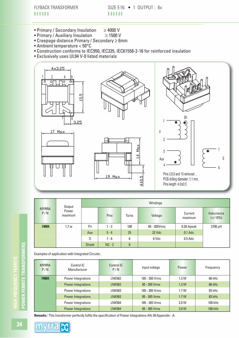
FLYBACK TRANSFORMER SIZE E16 • 1 OUTPUT : 6v
• Primary / Secondary Insulation ≥ 4000 V• Primary / Auxiliary Insulation ≥ 1500 V• Creepage distance Primary / Secondary ≥ 6mm• Ambient temperature < 50°C• Construction conforms to IEC950, IEC335, IEC61558-2-16 for reinforced insulation • Exclusively uses UL94 V-0 listed materials
Examples of application with Integrated Circuits :
Remarks : This transformer perfectly fulfils the specification of Power Integrations AN-39 Appendix - A.
MYRRA
P / NPins Turns Voltage
Current
maximum
Inductance
(+/-10%)
74004 1.7 w Pri 1 - 2 108 85 - 265Vrms 0.28 Apeak 2700 µH
Aux 5 - 4 25 22 Vdc 0.1 Adc
S 7 - 6 8 6 Vdc 0.5 Adc
Shield NC - 2 8
MYRRA
P / NFrequency
Control IC
P / NInput voltage
74004 Power Integrations LNK562 185 - 265 Vrms 1.3 W 66 kHz
Power integrations LNK562 85 - 265 Vrms 1.3 W 66 kHz
Power Integrations LNK563 185 - 265 Vrms 1.7 W 83 kHz
Power Integrations LNK563 85 - 265 Vrms 1.7 W 83 kHz
Power Integrations LNK564 185 - 265 Vrms 2.0 W 100 kHz
Power Integrations LNK564 85 - 265 Vrms 2.0 W 100 kHz

Output
Power
maximum
PO
WE
R F
ER
RIT
E T
RA
NS
FOR
ME
RS
HIG
H F
RE
QU
EN
CY
FE
RR
ITE
35
Frequency
Windings
FLYBACK TRANSFORMER SIZE E16 • 1 OUTPUT : 10v
• Primary / Secondary Insulation ≥ 4000 V• Primary / Auxiliary Insulation ≥ 1500 V• Creepage distance Primary / Secondary ≥ 6mm• Ambient temperature < 50°C• Construction conforms to IEC950, IEC335, IEC61558-2-16 for reinforced insulation • Exclusively uses UL94 V-0 listed materials
MYRRA
P / NPins Turns Voltage
Current
maximum
Inductance
(+/-10%)
74005 1.7 w Pri 1 - 2 108 85 - 265Vrms 0.28 Apeak 2700 µH
Aux 5 - 4 25 22 Vdc 0.1 Adc
S 7 - 6 12 10 Vdc 0.2 Adc
Shield NC - 2 8
PowerControl IC
Manufacturer
Examples of application with Integrated Circuits :
Remarks : This transformer perfectly fulfils the specification of Power Integrations AN-39 Appendix - B.
MYRRA
P / N
Control IC
P / NInput voltage
74005 Power Integrations LNK562 185 - 265 Vrms 1.3 W 66 kHz
Power integrations LNK562 85 - 265 Vrms 1.3 W 66 kHz
Power Integrations LNK563 185 - 265 Vrms 1.7 W 83 kHz
Power Integrations LNK563 85 - 265 Vrms 1.7 W 83 kHz
Power Integrations LNK564 185 - 265 Vrms 2.0 W 100 kHz
Power Integrations LNK564 85 - 265 Vrms 2.0 W 100 kHz

Output
Power
maximum
Frequency
Windings
FLYBACK TRANSFORMER SIZE E16 • 2 OUTPUTS : 5 & 12v
PIN 3 Removed PCB Drilling Diameter = 1.1mm
+S2 0V +S1 0V +E DRAIN +AUX 0V
Bottom View (Pin side)
74010
• Primary / Secondary Insulation ≥ 4000V• Primary / Auxiliary Insulation ≥ 1500V• Creepage distance Primary / Secondary ≥ 6mm• Ambient temperature < 50°C• Construction conforms to IEC950, IEC335, IEC61558-2-16 for reinforced insulation • Exclusively uses UL94-V0 listed materials
Examples of application with Integrated Circuits :
MYRRA
P / N
Control IC
ManufacturerInput voltage Power
MYRRA
P / NPins Turns Voltage
Current
maximum
Inductance
(+/-10%)
74010 12 w Pri 4 - 6 120 85 - 265Vrms 0.55 Apeak 1660µH
Aux 2 - 1 14 7 – 14 Vdc 0.1 Adc
S1 9 - 10 7 3.3 – 7 Vdc 2 Adc
S2 7 - 8 17 8 – 17 Vdc 1 Adc
74010 Power Integrations 185 - 265Vrms 12w 132kHz
Power Integrations 85 - 265Vrms 10w 132kHz
Power Integrations 185 - 265Vrms 12w 132kHz
Power Integrations 85 - 265Vrms 10w 132kHz
Power Integrations 185 - 265Vrms 12w 132kHz
ST Microelectronics 85 - 265Vrms 8w 70kHz
ST Microelectronics 185 - 265Vrms 10w 70kHz
Motorola 85 - 265Vrms 8w 100kHz
Motorola 185 - 265Vrms 10w 100kHz
Infineon 92 - 265Vrms 7,5w 100kHz
Infineon 185 - 265Vrms 10w 100kHz
Fairchild 85 - 265Vrms 7w 50kHz
Fairchild 185 - 265Vrms 10w 100kHz
PO
WE
R F
ER
RIT
E T
RA
NS
FOR
ME
RS
HIG
H F
RE
QU
EN
CY
FE
RR
ITE
36

Frequency
FLYBACK TRANSFORMER SIZE E16 • 2 OUTPUTS : 2 x 24v
PO
WE
R F
ER
RIT
E T
RA
NS
FOR
ME
RS
HIG
H F
RE
QU
EN
CY
FE
RR
ITE
37
PIN 3 Removed PCB Drilling Diameter = 1.1mm
+S2 0V +S1 0V +E DRAIN +AUX 0V
Bottom View (Pin side)
74014
• Primary / Secondary Insulation ≥ 4000V
• Primary / Auxiliary Insulation ≥ 1500V
• Creepage distance Primary / Secondary ≥ 6mm
• Ambient temperature < 50°C
• Construction conforms to IEC950, IEC335, IEC61558-2-16 for reinforced insulation
• Exclusively uses UL94-V0 listed materials
Examples of application with Integrated Circuits :
MYRRA
P / N
Control IC
ManufacturerInput voltage Power
74014 Power Integrations 185 - 265Vrms 12w
Power Integrations 85 - 265Vrms 8w
Power Integrations 185 - 265Vrms 12w 132kHz
Power Integrations 85 - 265Vrms 8w 132kHz
Typical outputs : +24V 0.5A with S1 – S2 in parallel
+48V 0.25A with S1 – S2 in series (8-9 connected)
+15V / -15V 0.4A with pins 8-9 connected to 0V
Output
Power
maximum
Windings
MYRRA
P / NPins Turns Voltage
Current
maximum
Inductance
(+/-10%)
74014 12 w Pri 4 - 6 120 85 - 265Vrms 0.5 Apeak 1800µH
Aux 2 - 1 17 9 – 18 Vdc 0.2 Adc
S1 9 - 10 27 15 – 30 Vdc 0.4 Adc
S2 7 - 8 27 15 – 30 Vdc 0.4 Adc

Output
Power
maximum
Windings
Frequency
FLYBACK TRANSFORMER SIZE E16 • 3 OUTPUTS : 5 / 15 / 24v
PO
WE
R F
ER
RIT
E T
RA
NS
FOR
ME
RS
HIG
H F
RE
QU
EN
CY
FE
RR
ITE
38
PIN 3 Removed PCB Drilling Diameter = 1.1mm
+S3 +S2 +S1 0V +E DRAIN +AUX 0V
Bottom View (Pin side)
74015
• Primary / Secondary Insulation ≥ 4000V
• Primary / Auxiliary Insulation ≥ 1500V
• Creepage distance Primary / Secondary ≥ 6mm
• Ambient temperature < 50°C
• Construction conforms to IEC950, IEC335, IEC61558-2-16 for reinforced insulation
• Exclusively uses UL94-V0 listed materials
Examples of application with Integrated Circuits :
MYRRA
P / N
Control IC
ManufacturerInput voltage Power
74015 Power Integrations 185 - 265Vrms 10w
Power Integrations 85 - 265Vrms 8w
Power Integrations 185 - 265Vrms 12w 132kHz
Power Integrations 85 - 265Vrms 9w 132kHz
MYRRA
P / NPins Turns Voltage
Current
maximum
Inductance
(+/-10%)
74015 12 w Pri 4 - 6 120 85 - 265Vrms 0.5 Apeak 1800µH
Aux 2 - 1 14 12 Vdc 0.2 Adc
S1 9 - 10 6 5 Vdc 1.5 Adc
S2 8 - 10 17 15 Vdc 0.6 Adc
S3 7 - 10 27 24 Vdc 0.4 Adc

Output
Power
maximum
Frequency
Windings
FLYBACK TRANSFORMER SIZE EL19 • 2 OUTPUTS : 5 & 12v
PO
WE
R F
ER
RIT
E T
RA
NS
FOR
ME
RS
HIG
H F
RE
QU
EN
CY
FE
RR
ITE
39
E DRAIN+ AUX0V
+S2 0V +S1 0V
Bottom View (Pin side)
74020 / 74021
PCB Drilling Diameter = 1.1mm
• Primary / Secondary Insulation ≥ 4000V• Primary / Auxiliary Insulation ≥ 1500V• Creepage distance Primary / Secondary ≥ 6mm• Ambient temperature < 50°C• Construction conforms to IEC950, IEC335, IEC61558-2-16 for reinforced insulation • Exclusively uses UL94-V0 listed materials
Examples of application with Integrated Circuits :
MYRRA
P / N
Control IC
ManufacturerInput voltage Power
MYRRA
P / NPins Turns Voltage
Current
maximum
Inductance
(+/-10%)
74020 Power Integrations 85 - 265Vrms 15w 132kHz
Power Integrations 185 - 265Vrms 18w 132kHz
Power Integrations 85 - 265Vrms 12w 132kHz
ST Microelectronics 85 - 265Vrms 10w 100kHz
ST Microelectronics 185 - 265Vrms 12w 100kHz
ST Microelectronics 185 - 265Vrms 16w 100kHz
Motorola 185 - 265Vrms 16w 100kHz
Infineon 185 - 265Vrms 16w 100kHz
74021 ST Microelectronics 85 - 265Vrms 13w 70kHz
Motorola 85 - 265Vrms 13w 100kHz
Infineon 92 - 265Vrms 10w 100kHz
74020 18 w Pri 4 - 6 108 85 - 265Vrms 0.8 Apeak 1250µH
Aux 2 - 1 12 7 – 14 Vdc 0.1 Adc
S1 9 - 10 6 3.3 – 7 Vdc 3 Adc
S2 7 - 8 14 8 – 16.5 Vdc 1.4 Adc
74021 18 w Pri 4 - 6 108 85 - 265Vrms 1.1 Apeak 900µH
Aux 2 - 1 12 7 – 14 Vdc 0.1 Adc
S1 9 - 10 6 3.3 – 7 Vdc 3 Adc
S2 7 - 8 14 8 – 16.5 Vdc 1.4 Adc

Output
Power
maximum
74023 16 w Pri 9 – 10 120 85 - 265Vrms 0.85 Apeak 1250µH
Aux 8 – 7 17 15 Vdc 0.2 Adc
S1 5 – 6 4 3.3 Vdc S1 + S2 : 7 Adc
S2 4 – 6 6 5 Vdc S1 + S2 : 7 Adc
S3 3 – 6 14 12 Vdc 0.8 Adc
S4 2 – 6 20 18 Vdc 0.8 Adc
S5 1 – 6 33 30 Vdc 0.2 Adc
Windings
Power
PO
WE
R F
ER
RIT
E T
RA
NS
FOR
ME
RS
HIG
H F
RE
QU
EN
CY
FE
RR
ITE
40
Frequency
FLYBACK TRANSFORMER SIZE EL19 • 5 OUTPUTS : 3.3 / 5 / 12 / 18 / 30v
Bottom View (Pin side)
E 10 DRAIN 9 +Aux 8 0v 7
1 +S5 2 +S4 3 +S3 4 +S2 5 +S1 6 0V
PCB Drilling Diameter = 1.1mm
74023
• Primary / Secondary Insulation ≥ 4000V
• Primary / Auxiliary Insulation ≥ 1500V
• Creepage distance Primary / Secondary ≥ 6mm
• Ambient temperature < 60°C
• Construction conforms to IEC950, IEC335, IEC61558-2-16 for reinforced insulation
• Exclusively uses UL94-V0 listed materials
Examples of application with Integrated Circuits :
MYRRA
P / N
Control IC
ManufacturerInput voltage
MYRRA
P / NPins Turns Voltage
Current
maximum
Inductance
(+/-10%)
74023 Power Integrations 185 - 265Vrms 16w 132kHz
Power Integrations 85 - 265Vrms 12w 132kHz

Output
Power
maximum
Control IC
ManufacturerFrequency
Windings
MYRRA
P / NPins Turns Voltage
Current
maximum
Inductance
(+/-10%)
FLYBACK TRANSFORMER SIZE EF20 • 2 or 3 OUTPUTS : 5/5v or 12/12v or 3.3+5/12v
PO
WE
R F
ER
RIT
E T
RA
NS
FOR
ME
RS
HIG
H F
RE
QU
EN
CY
FE
RR
ITE
41
• Primary / Secondary Insulation ≥ 4000V • Primary / Auxiliary Insulation ≥ 1500V• Creepage distance Primary / Secondary ≥ 8mm• Ambient temperature < 50°C• Construction conforms to IEC950, IEC335, IEC61558-2-16 for reinforced insulation • Exclusively uses UL94-V0 listed materials
Examples of application with Integrated Circuits :
PIN 3 Removed PCB Drilling Diameter = 1.2mm
+S2 +S1 0V +S3 0V +E DRAIN+AUX 0V
+E DRAIN+AUX 0V+S1 0V +S2 0V
74088
74087 - 74089
PowerMYRRA
P / NInput voltage
74087
Power Integrations 185 - 265Vrms 24w 132kHz
Power Integrations 85 - 265Vrms 15w 132kHz
74088
Power Integrations 185 - 265Vrms 20w 132kHz
Power Integrations 85 – 265Vrms 12w 132kHz
Power Integrations 185 - 265Vrms 20w 132kHz
74089 Power Integrations 85 – 265Vrms 14w 132kHz
Power Integrations 185 - 265Vrms 17w < 120kHz
74087
24 w Pri 4 – 5 86 85 - 265Vrms 1.0 Apeak 1000µH
Aux 2 – 1 12 11 - 18 Vdc 0.3 Adc
S1 6 – 7 10 9 – 15 Vdc 1.5 Adc
S2 9 – 10 10 9 – 15 Vdc 1.5 Adc
74088
20 w Pri 4 – 5 80 85 - 265Vrms 0.9 Apeak 1100µH
Aux 2 – 1 17 15 Vdc 0.3 Adc
S1 7 – 8 4 3.3 Vdc S1 + S2 : 7 Adc
S2 6 – 8 6 5 Vdc S1 + S2 : 7 Adc
S3 9 – 10 14 12 Vdc 1.3 Adc
74089
20 w Pri 4 – 5 86 85 - 265Vrms 0.85 Apeak 1300µH
Aux 2 – 1 12 7 - 18 Vdc 0.3 Adc
S1 6 – 7 5 3 – 7.5 Vdc 2.0 Adc
S2 9 – 10 5 3 – 7.5 Vdc 2.0 Adc

Output
Power
maximum
Frequency
Windings
74030 30 w Pri 3 – 5 70 85 - 265Vrms 1.5 Apeak 750µH
Aux 2 – 1 8 7 – 14.5 Vdc 1 Adc
S1 7 – 8 4 3.3 - 7 3 Adc
S2 6 – 8 9 8 – 16 Vdc 1.5 Adc
S3 9 – 10 9 8 – 16 Vdc 1.5 Adc
74032 35 w Pri 3 – 5 72 85 - 265Vrms 1.1 Apeak 1100µH
Aux 2 – 1 10 8 - 16 Vdc 1 Adc
S1 6 – 10 18 15 - 30 Vdc 1.4 Adc
PO
WE
R F
ER
RIT
E T
RA
NS
FOR
ME
RS
HIG
H F
RE
QU
EN
CY
FE
RR
ITE
42
FLYBACK TRANSFORMER SIZE E25 • 3 or 1 OUTPUTS : 5+12/12v or 24v
PIN 4 Removed PCB Drilling Diameter = 1.4mmBottom View (Pin side)
+S1 0V +E DRAIN+AUX 0V
+E DRAIN+AUX 0V+S2 +S1 0V +S3 0V 74030
74032
• Primary / Secondary Insulation ≥ 4000V• Primary / Auxiliary Insulation ≥ 1500V• Creepage distance Primary / Secondary ≥ 6mm• Ambient temperature < 50°C• Construction conforms to IEC950, IEC335, IEC61558-2-16 for reinforced insulation • Exclusively uses UL94-V0 listed materials
MYRRA
P / NPins Turns Voltage
Current
maximum
Inductance
(+/-10%)
Note for 74030 : S2 and S3 can be connected in series or in parallel
Examples of application with Integrated Circuits :
MYRRA
P / N
Control IC
ManufacturerInput voltage Power
74030 Power Integrations 185 - 265Vrms 30w 132kHz
Power Integrations 85 - 265Vrms 25w 66 or 132kHz
ST Microelectronics 85 - 265Vrms 22w 70kHz
ST Microelectronics 185 - 265Vrms 30w 70kHz
Motorola 85 - 265Vrms 22w 100kHz
Motorola 185 - 265Vrms 30w 100kHz
Infineon 185 - 265Vrms 30w 100kHz
Fairchild 85 - 265Vrms 22w 100kHz
74032 Power Integrations 185 - 265Vrms 25w 132kHz

Output
Power
maximum
Frequency
Windings
PO
WE
R F
ER
RIT
E T
RA
NS
FOR
ME
RS
HIG
H F
RE
QU
EN
CY
FE
RR
ITE
43
FLYBACK TRANSFORMER SIZE ETD29 • 4 OUTPUTS : 5+12 / 5+12v
• Primary / Secondary Insulation ≥ 4000V
• Primary / Auxiliary Insulation ≥ 1500V
• Creepage distance Primary / Secondary ≥ 8mm
• Ambient temperature < 50°C
• Construction conforms to IEC950, IEC335, IEC61558-2-16 for reinforced insulation
• Exclusively uses UL94-V0 listed materials
PIN 4 Removed PCB Drilling Diameter = 1.3mmBottom View (Pin side)
+E DRAIN +AUX 0V
+S4 +S3 0V +S2 +S1 0V
Examples of application with Integrated Circuits :
MYRRA
P / N
Control IC
ManufacturerInput voltage Power
MYRRA
P / NPins Turns Voltage
Current
maximum
Inductance
(+/-10%)
74040 60 w Pri 5 – 7 50 85 - 265Vrms 3.0 Apeak 500µH
Aux 3 – 2 6 7 – 14.5 Vdc 0.5 Adc
S1 12 – 13 3 3.3 - 7 4 Adc
S2 11 – 13 7 8 – 16.5 Vdc 2.5 Adc
S3 9 – 10 3 3.3 - 7 4 Adc
S4 8 - 10 7 8 – 16.5 Vdc 2.5 Adc
Note : S1 / S3 or S2 / S4 can be connected in series or in parallel
74040 Power Integrations 185 - 265Vrms 60w 66 or 132kHz
Power Integrations 85 - 265Vrms 45w 66 or 132kHz
ST Microelectronics 85 - 265Vrms 35w 100kHz
ST Microelectronics 185 - 265Vrms 45w 100kHz
Motorola 85 - 265Vrms 35w 100kHz
Motorola 185 - 265Vrms 45w 100kHz
Infineon 92 - 265Vrms 35w 100kHz
Infineon 185 - 265Vrms 45w 100kHz

Output
Power
maximum
74043 60w Pri 5 – 1 45 85 - 265Vrms 3 Apeak 500µH
Aux 8 – 9 7 15 Vdc 0.5 Adc
S1 14+15 / 12+13 2 3.3 Vdc S1+S2 : 7 Adc
S2 11 / 12+13 3 5 Vdc S1+S2 : 7 Adc
S3 16 – 10 4 12 Vdc 2 Adc
S4 17 – 10 7 18 Vdc 2 Adc
S5 18 – 10 13 30 Vdc 0.5 Adc
Frequency
Windings
PO
WE
R F
ER
RIT
E T
RA
NS
FOR
ME
RS
HIG
H F
RE
QU
EN
CY
FE
RR
ITE
44
FLYBACK TRANSFORMER SIZE ERL28 • 5 OUTPUTS : 3.3 / 5 / 12 / 18 / 30v
Bottom View (Pin side)PCB Drilling Diameter = 1.3mm
E 1 DRAIN 5 +Aux 8 0v 9
18 +30v 17 +18v 16 +12v 10 +5v(dc) 11 +5v(ac) 14,15 +3v3 12,13 0v
• Primary / Secondary Insulation ≥ 4000V
• Primary / Auxiliary Insulation ≥ 1500V
• Creepage distance Primary / Secondary ≥ 6mm
• Ambient temperature < 50°C
• Construction conforms to IEC950, IEC335, IEC61558-2-16 for reinforced insulation
• Exclusively uses UL94-V0 listed materials
Power
Examples of application with Integrated Circuits :
MYRRA
P / N
Control IC
ManufacturerInput voltage
MYRRA
P / NPins Turns Voltage
Current
maximum
Inductance
(+/-10%)
74043 Power Integrations 185 - 265Vrms 60w 66 or 132kHz
Power Integrations 85 - 265Vrms 45w 66 or 132kHz

Output
Power
maximum
Frequency
Windings
PO
WE
R F
ER
RIT
E T
RA
NS
FOR
ME
RS
HIG
H F
RE
QU
EN
CY
FE
RR
ITE
45
FLYBACK TRANSFORMER SIZE ETD34 • 4 OUTPUTS : 5+12 / 5+12v
• Primary / Secondary Insulation ≥ 4000V
• Primary / Auxiliary Insulation ≥ 1500V
• Creepage distance Primary / Secondary ≥ 8mm
• Ambient temperature < 50°C
• Construction conforms to IEC950, IEC335, IEC61558-2-16 for reinforced insulation
• Exclusively uses UL94-V0 listed materials
PIN 4 Removed PCB Drilling Diameter = 1.5mmBottom View (Pin side)
+E DRAIN +AUX 0V
+S4 +S3 0V +S2 +S1 0V
Examples of application with Integrated Circuits :
MYRRA
P / N
Control IC
ManufacturerInput voltage Power
MYRRA
P / NPins Turns Voltage
Current
maximum
Inductance
(+/-10%)
74050 90 w Pri 5 – 7 36 85 - 265Vrms 2.8 Apeak 500µH
Aux 3 – 2 4 7 – 14 Vdc 0.5 Adc
S1 12 – 13 2 3.3 – 6.5 5 Adc
S2 11 – 13 5 8.5 – 17 Vdc 3 Adc
S3 9 – 10 2 3.3 – 6.5 5 Adc
S4 8 - 10 5 8.5 – 17 Vdc 3 Adc
Note : S1 / S3 or S2 / S4 can be connected in series or in parallel
74050 Power Integrations 185 - 265Vrms 90w 132kHz
Power Integrations 85 - 265Vrms 60w 66 or 132kHz
ST Microelectronics 185 - 265Vrms 80w 70kHz
ST Microelectronics 85 - 265Vrms 60w 70kHz
Motorola 185 - 265Vrms 80w 100kHz
Motorola 85 - 265Vrms 60w 100kHz
Infineon 185 - 265Vrms 80w 100kHz
Infineon 85 - 265Vrms 60w 100kHz

Output
Power
maximum
Frequency
Windings
MYRRA
P / NPins Turns Voltage
Current
maximum
Inductance
(+/-10%)
74060 140 w Pri 5 – 7 36 85 - 265Vrms 4 Apeak 440µH
Aux 3 – 2 4 7 – 14 Vdc 0.5 Adc
S1 14 – 15 2 3.3 – 6.5 5 Adc
S2 13 – 15 5 8.5 – 17 Vdc 5 Adc
S3 11 – 12 2 3.3 – 6.5 5 Adc
S4 10 – 12 5 8.5 – 17 Vdc 5 Adc
Note : S1 / S3 or S2 / S4 can be connected in series or in parallel
Examples of application with Integrated Circuits :
MYRRA
P / N
Control IC
ManufacturerInput voltage Power
74060 Power Integrations 185 - 265Vrms 140w 132kHz
Power Integrations 85 - 265Vrms 90w 66 or 132kHz
ST Microelectronics 85 - 265Vrms 70w 70kHz
ST Microelectronics 185 - 265Vrms 120w 100kHz
Motorola 85 - 265Vrms 70w 100kHz
Motorola 185 - 265Vrms 120w 100kHz
Infineon 85 - 265Vrms 70w 100kHz
Infineon 185 - 265Vrms 120w 100kHz
Fairchild 85 - 265Vrms 70w 100kHz
Fairchild 185 - 265Vrms 120w 100kHz
PO
WE
R F
ER
RIT
E T
RA
NS
FOR
ME
RS
HIG
H F
RE
QU
EN
CY
FE
RR
ITE
46
FLYBACK TRANSFORMER SIZE ETD39 • 4 OUTPUTS : 5+12 / 5+12v
PIN 4 Removed PCB Drilling Diameter = 1.5mmBottom View (Pin side)
+E DRAIN +AUX 0V
+S4 +S3 0V +S2 +S1 0V
• Primary / Secondary Insulation ≥ 4000V
• Primary / Auxiliary Insulation ≥ 1500V
• Creepage distance Primary / Secondary ≥ 8mm
• Ambient temperature < 50°C
• Construction conforms to IEC950, IEC335, IEC61558-2-16 for reinforced insulation
• Exclusively uses UL94-V0 listed materials

Output
Power
maximum
Frequency
Windings
PO
WE
R F
ER
RIT
E T
RA
NS
FOR
ME
RS
HIG
H F
RE
QU
EN
CY
FE
RR
ITE
47
FLYBACK TRANSFORMER SIZE ETD44 • 4 OUTPUTS : 5+12 / 5+12v
• Primary / Secondary Insulation ≥ 4000V
• Primary / Auxiliary Insulation ≥ 1500V
• Creepage distance Primary / Secondary ≥ 8mm
• Ambient temperature < 50°C
• Construction conforms to IEC950, IEC335, IEC61558-2-16 for reinforced insulation
• Exclusively uses UL94-V0 listed materials
PIN 4 Removed PCB Drilling Diameter = 1.5mmBottom View (Pin side)
+E DRAIN +AUX 0V
+S4 +S3 0V +S2 +S1 0V
Examples of application with Integrated Circuits :
MYRRA
P / N
Control IC
ManufacturerInput voltage Power
MYRRA
P / NPins Turns Voltage
Current
maximum
Inductance
(+/-10%)
74070 180 w Pri 5 – 7 38 85 - 265Vrms 8 Apeak 300µH
Aux 3 – 2 4 7 – 14 Vdc 0.5 Adc
S1 16 – 17 2 3.3 – 6.5 6 Adc
S2 15 – 17 5 8.5 – 17 Vdc 5 Adc
S3 13 – 14 2 3.3 – 6.5 6 Adc
S4 12 – 14 5 8.5 – 17 Vdc 5 Adc
Note : S1 / S3 or S2 / S4 can be connected in series or in parallel
74070 Power Integrations 185 - 265Vrms 180w 66 or 132kHz
Power Integrations 85 - 265Vrms 120w 66kHz
Infineon 185 - 265Vrms 160w 100kHz
Fairchild 185 - 265Vrms 160w 100kHz
Philips 185 - 265Vrms 120w 50kHz

PO
WE
R F
ER
RIT
E T
RA
NS
FOR
ME
RS
HIG
H F
RE
QU
EN
CY
FE
RR
ITE
48
FLYBACK TRANSFORMER 1 TO 35 W FLYBACK TRANSFORMERS STANDARD SIZES

Current range
74330 - 74335 U9.8 1.5 to 47mH 0.18 to 1.1A
74300 - 74306 U10.5 1.5 to 68mH 0.30 to 1.9A
74310 - 74315 U16 1.5 to 33mH 0.75 to 3.3A
74320 - 74325 E25 1.5 to 33mH 0.90 to 4.0A
CU
RR
EN
T T
RA
NS
FOR
ME
RS
RA
NG
E
HIG
H F
RE
QU
EN
CY
FE
RR
ITE
49
COMMON MODE CHOKES RANGE FOR EMI SUPPRESSION
• Mainly used to reduce noise conducted through power or signal lines.
• The common mode inductance filters symmetrical noise, associated with Y-type safety capaci-
tors connected to ground.
• The differential mode inductance filters asymmetrical noise, associated with X-type capacitor
connected between Line and Neutral.
U9.8 U10.5 U16 E25
Inductance rangeMYRRA
Part N°SIZE
• Toroidal Common Mode Chokes - Custom design available upon request

MYRRA
Inductance Rated Resistance Inductance Resonant
Part N°
Common Mode Current per winding Differential Mode Frequency
min - max (mH) Arms ohm max µH min kHz min
74330 33 - 56 0.18 7 710 210
74331 18 - 31 0.26 3.5 360 280
74332 10 - 17 0.35 2.0 210 400
74333 4.7 - 8 0.5 .95 100 610
74334 2.2 - 3.7 0.8 .4 45 910
74335 1 - 1.7 1.1 .21 20 1300
CU
RR
EN
T T
RA
NS
FOR
ME
RS
RA
NG
E
HIG
H F
RE
QU
EN
CY
FE
RR
ITE
50
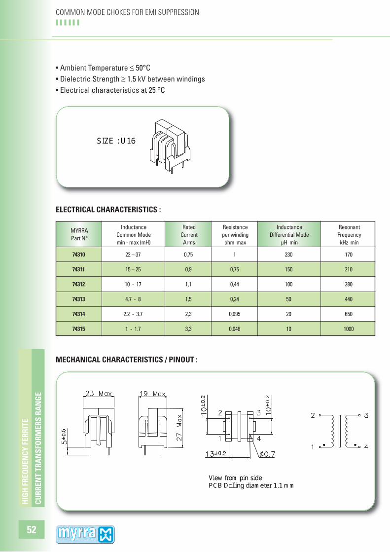
COMMON MODE CHOKES FOR EMI SUPPRESSION
• Ambient Temperature ≤ 50°C
• Dielectric Strength ≥ 1.5 kV between windings
• Electrical characteristics at 25 °C
SIZE : U9.8
ELECTRICAL CHARACTERISTICS :
View from pin side PCB Drilling diameter 1.0 mm
MECHANICAL CHARACTERISTICS / PINOUT :

MYRRA
Inductance Rated Resistance Inductance Resonant
Part N°
Common Mode Current per winding Differential Mode Frequency
min - max (mH) Arms ohm max µH min kHz min
• Ambient Temperature ≤ 50°C
• Dielectric Strength ≥ 1.5 kV between windings
• Electrical characteristics at 25 °C
SIZE : U10.5
ELECTRICAL CHARACTERISTICS :
View from pin side PCB Drilling diameter 1.1 mm
MECHANICAL CHARACTERISTICS / PINOUT :C
UR
RE
NT
TR
AN
SFO
RM
ER
S R
AN
GE
HIG
H F
RE
QU
EN
CY
FE
RR
ITE
51
COMMON MODE CHOKES FOR EMI SUPPRESSION
74306 51 - 85 0.3 4 530 125
74300 33 - 56 0,35 3 400 170
74301 18 - 31 0,45 1,7 240 220
74302 10 - 17 0,6 1 140 320
74303 4.7 - 8 0,9 0,43 65 480
74304 2.2 - 3.7 1,3 0,23 32 740
74305 1 - 1.7 1,9 0,1 14 1000
MYRRA
Inductance Rated Resistance Inductance Resonant
Part N°
Common Mode Current per winding Differential Mode Frequency
min - max (mH) Arms ohm max µH min kHz min
74310 22 – 37 0,75 1 230 170
74311 15 – 25 0,9 0,75 150 210
74312 10 - 17 1,1 0,44 100 280
74313 4.7 - 8 1,5 0,24 50 440
74314 2.2 - 3.7 2,3 0,095 20 650
74315 1 - 1.7 3,3 0,046 10 1000
CU
RR
EN
T T
RA
NS
FOR
ME
RS
RA
NG
E
HIG
H F
RE
QU
EN
CY
FE
RR
ITE
52
COMMON MODE CHOKES FOR EMI SUPPRESSION
• Ambient Temperature ≤ 50°C
• Dielectric Strength ≥ 1.5 kV between windings
• Electrical characteristics at 25 °C
SIZE : U16
ELECTRICAL CHARACTERISTICS :
View from pin side PCB Drilling diameter 1.1 mm
MECHANICAL CHARACTERISTICS / PINOUT :

74320 22 – 37 0,9 0,54 130 170
74321 15 – 25 1,1 0,35 90 210
74322 10 - 17 1,3 0,22 50 270
74323 4.7 - 8 1,8 0,105 25 400
74324 2.2 - 3.7 2,7 0,05 11 630
74325 1 - 1.7 4 0,03 7 950
MYRRA
Inductance Rated Resistance Inductance Resonant
Part N°
Common Mode Current per winding Differential Mode Frequency
min - max (mH) Arms ohm max µH min kHz min
• Ambient Temperature ≤ 50°C
• Dielectric Strength ≥ 1.5 kV between windings
• Electrical characteristics at 25 °C
SIZE : E25
ELECTRICAL CHARACTERISTICS :
View from pin side PCB Drilling diameter 1.2 mm
MECHANICAL CHARACTERISTICS / PINOUT :
CU
RR
EN
T T
RA
NS
FOR
ME
RS
RA
NG
E
HIG
H F
RE
QU
EN
CY
FE
RR
ITE
53
COMMON MODE CHOKES FOR EMI SUPPRESSION

Approx.
Weight
74190 150 w 3.5 mH 0.7 Arms 1.5 Ω 22 nF 24 9 9.5 0.5 13 g
74191 300 w 2.8 mH 1.3 Arms 0.73 Ω 47 nF 29 10 12 0.7 24 g
74192 500 w 2.0 mH 2.2 Arms 0.35 Ω 82 nF 32.5 9 16 0.9 47 g
74196 500 w 1.8 mH 2.2 Arms 0.37 Ω 82 nF 38 14 12 0.9 39 g
74193 1000 w 1.3 mH 4.5 Arms 0.15 Ω 220 nF 44 14 16.5 1.2 80 g
74194 2200 w 450 µH 10 Arms 0.04 Ω 470 nF 50 12 22.5 1.8 140 g
74195 4500 w 250 µH 20 Arms 0.014 Ω 1 µF 58 10 28 2.5 250 g
TO
RO
IDA
L C
HO
KE
S
HIG
H F
RE
QU
EN
CY
FE
RR
ITE
54
DIMMER CHOKES FOR EMI SUPPRESSION
• For noise suppression in light dimmers
• Saturable chokes : provides a high impedance for Triac switching
interferences, and a low impedance for 50Hz component.
• Electrical characteristics at 25 °
ELECTRICAL CHARACTERISTICS :
L = 25 +/-10mm
MECHANICAL CHARACTERISTICS :
Power
Dimensions (mm)
MYRRA
Part N°
Inductance
+/- 15 %
Rated
CurrentResistance
Associated
Capacitor OD
max
ID
min
H
max
W
max

Current range
Current range
E13 E19-V E19-H E25 T40 U10.5 T15 T18 T30
CU
RR
EN
T T
RA
NS
FOR
ME
RS
RA
NG
E
HIG
H F
RE
QU
EN
CY
FE
RR
ITE
55
CURRENT TRANSFORMERS RANGE
• FOR MAINS AC CURRENT MEASUREMENT - 50 to 400 Hz
• FOR SWITCH MODE POWER SUPPLIES - 20 to 150kHz
RatioMYRRA
Part N°SIZE
RatioMYRRA
Part N°SIZE
PIN PRIMARY - up to 25A
74520 Size E19-H Ratio 1 / 1 / 100 Current 10 A/ 20 A
74530 Size E25 Ratio 1 / 1 / 100 Current 12.5 A/ 25 A
74550 Size E13 Ratio 1 / 100 Current 10 A
74560 Size U10.5 Ratio 1 / 100 Current 10 A
74562 Size U10.5 Ratio 1 / 100 Current 10 A
74570 Size T15 Ratio 1 / 1 / 50 Current 10 A/ 20 A
THRU-HOLE PRIMARY - up to 200A
74500 Size T18 Ratio 1 / 50 Current 15 A
74501 Size T18 Ratio 1 / 100 Current 25 A
74502 Size T18 Ratio 1 / 200 Current 25 A
74510 Size T30 Ratio 1 / 100 Current 150 A
74540, 74541, 74542 Size T40 Ratio 1 / 100 Current 200 A
PIN PRIMARY - up to 25A
74521 Size E19-H Ratio 1 / 1 / 750 Current 10 A / 20 A
74523 Size E19-V Ratio 1 / 500 Current 15 A
74531 Size E25 Ratio 1 / 1 / 1000 Current 12.5 A / 25 A
74533 Size E25 Ratio 1 / 1000 Current 8 A
74534 Size E25 Ratio 1 / 350 Current 4 A
74561 Size U10.5 Ratio 1 / 2000 Current 8 A
THRU-HOLE PRIMARY - up to 250A
74503 Size T18 Ratio 1 / 1000 Current 12 A
74504 Size T18 Ratio 1 / 750 Current 10 A
74511 Size T30 Ratio 1 / 1000 Current 60 A
74543, 74544, 74545 Size T40 Ratio 1 / 500 Current 100 A
74546, 74547, 74548 Size T40 Ratio 1 / 1000 Current 250 A

Typical Load/
Accuracy/ Current
Sec.
Turns
74500
50 15 A 0.6 Ω 5 175 V.µS 15 V 50 Ω / 1% / 15 A
20 – 200 kHz 20 – 200 kHz
74501
100 25 A 1.5 Ω 20 350 V.µS 25 V 100 Ω / 1% / 25 A
20 – 100 kHz 20 – 100 kHz
74502
200 25 A 5 Ω 80 700 V.µS 50 V 200 Ω / 1% / 25 A
20 – 100 kHz 20 – 100 kHz
74503
1000 12 A 45 Ω 2000 2.5 V.ms 0.15V/ 50 Hz/ 12A ≤ 10 Ω / 2% / 12 A
50 Hz 0.6V/ 50 Hz/ 8A ≤ 40 Ω / 2% / 8 A
74504
750 10 A 35 Ω 1100 2.0 V.ms 0.13V/ 50 Hz/ 10A ≤ 10 Ω / 2% / 10 A
50 Hz 0.3V/ 50 Hz/ 5A ≤ 40 Ω / 2% / 5 A
CU
RR
EN
T T
RA
NS
FOR
ME
RS
RA
NG
E
HIG
H F
RE
QU
EN
CY
FE
RR
ITE
56
TOROIDAL / THRU–HOLE
18 max
12.7 10 max 3 1
21 max
3 1
HOLE DIA 5Primary Current Direction
P 3 S 1
74500 / 74501 / 74502
74503 / 74504
Data applies for one primary turn (single passage of primary wire through toroid hole).
Sensitivity can be increased for lower currents by winding more than one turn.
MYRRA
Part N°
Max Pri.
Current
A rms
Pulse
Vsec x t max
@ Frequency
Sine
Vsec max
@ Frequency
Rsec.
Ωmax
Lsec.
mH
min

Typical Load/
Accuracy/ Current
74510/ 74511
P 7 S 2
Pin 8 removed for locating
Primary currentdirection
6 10
MYRRA
Part N°
Sec.
Turns
Max Pri.
Current
A rms
Pulse
Vsec x t max
@ Frequency
Sine
Vsec max
@ Frequency
Rsec.
Ωmax
Lsec.
mH
min
CU
RR
EN
T T
RA
NS
FOR
ME
RS
RA
NG
E
HIG
H F
RE
QU
EN
CY
FE
RR
ITE
57
TOROIDAL / THRU–HOLE
Data applies for one primary turn (single passage of primary wire through toroid hole).
Sensitivity can be increased for lower currents by winding more than one turn.
Models with 50, 100, 200 turns are designed for switch-mode power conversion
(up to 200 kHz).
Models with 500 and 1000 turns are designed for Mains current measurement (50 to 400 Hz).
74510 100 150 A 0.25Ω 40 1 V.ms/ 20 kHz
50 V/ 20 kHz 700 V µs/ 80 V/ 100 kHz
1 - 20 Ω / 1% 100 kHz
74511 1000 60 A 32 Ω 4000 10 V.ms/ 50 Hz 0.6 V/ 50 Hz/ 60 A ≤ 10 Ω / 1% / 60 A 1 V/ 50 Hz/ 40 A ≤ 20 Ω / 1% / 40 A

FOR MAINS AC CURRENT MEASUREMENT - 50 to 400 Hz
FOR SWITCH MODE POWER SUPPLIES - 20 to 150 kHz
74520 1/1/100 20 A parallel 1.5 8 400 V.µs 50 Vrms 10 – 100 Ω / 1% / 10 A 2500 V 10 A serie
CU
RR
EN
T T
RA
NS
FOR
ME
RS
RA
NG
E
HIG
H F
RE
QU
EN
CY
FE
RR
ITE
58
PIN PRIMARY TYPES
1 P1 4 2 P2 3
8 S 5
74520/ 74521
Pins 6 & 7 removed for locating
SAFETY :
These products are only composed of UL approved materials.
These products have a construction conform to CEI950, CEI335, CEI61558 for Basic insulation
(3 mm creepage distance)
MYRRA
Part N°
Typical Load/
Accuracy/ Current
Insulation
Voltage
P/ S
Ratio
Max Pri.
Current
A rms
Pulse
Vsec x t
max
Sine
Vsec
rms max
Rsec.
Ωmax
Lsec.
mH
min
74521 1/1/750 20 A parallel 10 A serie 57 300 15 V.ms 3 Vrms ≤ 75 Ω / 4% / 20 A 2500 V
MYRRA
Part N°
Typical Load/
Accuracy/ Current
Insulation
Voltage
P/ S
Ratio
Max Pri.
Current
A rms
Pulse
Vsec x t
max
Sine
Vsec
rms max
Rsec.
Ωmax
Lsec.
mH
min

FOR MAINS AC CURRENT MEASUREMENT - 50 to 400 Hz
1 P 2 4 S 3
74523
Pins 6 & 7 removed for locating
MYRRA
Part N°
Typical Load/
Accuracy/ Current
Insulation
Voltage
P/ S
Ratio
Max Pri.
Current
A rms
Pulse
Vsec x t
max
Sine
Vsec
rms max
Rsec.
Ωmax
Lsec.
mH
min
CU
RR
EN
T T
RA
NS
FOR
ME
RS
RA
NG
E
HIG
H F
RE
QU
EN
CY
FE
RR
ITE
59
PIN PRIMARY TYPES
SAFETY :
This product is only composed of UL approved materials.
This product has a construction conform to CEI950, CEI335, CEI61558 for Functional insulation
74523 1/ 500 15 A 155 670 30 V.ms 6 Vrms ≤ 50 Ω / 2% / 15 A 1500 V ≤ 200 Ω / 5% / 10 A

FOR MAINS AC CURRENT MEASUREMENT - 50 to 400 Hz
FOR SWITCH MODE POWER SUPPLIES - 20 to 150 kHz
74531 1/1/1000 25 A parallel 90 4 H 8 V.ms 1.6 Vrms ≤ 50 Ω / 2% / 20 A 2500 V 12.5 A serie
74533 1/ 1000 8 A 360 17 H 15 V.ms 3 Vrms ≤ 200 Ω / 1% / 8 A 2500 V ≤ 500 Ω / 1.5% / 5 A
74534 1/ 350 4 A 380 19 H 15 V.ms 3 Vrms ≤ 100 Ω / 1% / 4 A 2500 V ≤ 500 Ω / 1% / 2 A
74530 1/1/100 25 A parallel 1 10 600 V.µs 80 Vrms 10 - 100 Ω/ 1%/ 25 A 2500 V 12.5 A serie
CU
RR
EN
T T
RA
NS
FOR
ME
RS
RA
NG
E
HIG
H F
RE
QU
EN
CY
FE
RR
ITE
60
PIN PRIMARY TYPES
9 P 7 2 S 4
10 P1 6 9 P2 7
2 S 4
Pins 1 & 8 removed for locating
74530/ 74531
74533/ 74534
SAFETY :
These products are only composed of UL approved materials.
These products have a construction conform to CEI950, CEI335, CEI61558 for Basic insulation
(3 mm creepage distance)
MYRRA
Part N°
Typical Load/
Accuracy/ Current
Insulation
Voltage
P/ S
Ratio
Max Pri.
Current
A rms
Pulse
Vsec x t
max
Sine
Vsec
rms max
Rsec.
Ωmax
Lsec.
mH
min
MYRRA
Part N°
Typical Load/
Accuracy/ Current
Insulation
Voltage
P/ S
Ratio
Max Pri.
Current
A rms
Pulse
Vsec x t
max
Sine
Vsec
rms max
Rsec.
Ωmax
Lsec.
mH
min
Typical Load/
Accuracy/ Current
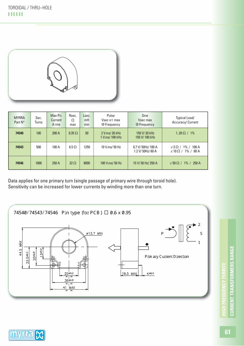
74540/ 74543/ 74546 Pin type (for PCB) 0.6 x 0.95
Primary Current Direction
P 2 S 1
CU
RR
EN
T T
RA
NS
FOR
ME
RS
RA
NG
E
HIG
H F
RE
QU
EN
CY
FE
RR
ITE
61
TOROIDAL / THRU–HOLE
74540 100 200 A 0.35 Ω 50 2 V.ms/ 20 kHz 150 V/ 20 kHz 1..20 Ω / 1% 1 V.ms/ 100 kHz 150 V/ 100 kHz
74543 500 100 A 6.5 Ω 1250 10 V.ms/ 50 Hz 0.7 V/ 50Hz/ 100 A ≤ 3 Ω / 1% / 100 A 1.2 V/ 50Hz/ 60 A ≤ 10 Ω / 1% / 60 A
74546 1000 250 A 22 Ω 8000 100 V.ms/ 50 Hz 15 V/ 50 Hz/ 250 A ≤ 50 Ω / 1% / 250 A
MYRRA
Part N°
Sec.
Turns
Max Pri.
Current
A rms
Pulse
Vsec x t max
@ Frequency
Sine
Vsec max
@ Frequency
Rsec.
Ωmax
Lsec.
mH
min
Data applies for one primary turn (single passage of primary wire through toroid hole).
Sensitivity can be increased for lower currents by winding more than one turn.

Typical Load/
Accuracy/ Current
CU
RR
EN
T T
RA
NS
FOR
ME
RS
RA
NG
E
HIG
H F
RE
QU
EN
CY
FE
RR
ITE
62
TOROIDAL / THRU–HOLE
74541/ 74544/ 74547 FASTON Connectors (4.8 x 0.8)P
2 S 1Primary Current Direction
74541 100 200 A 0.35 Ω 50 2 V.ms/ 20 kHz 150 V/ 20 kHz 1..20 Ω / 1% 1 V.ms/ 100 kHz 150 V/ 100 kHz
74544 500 100 A 6.5 Ω 1250 10 V.ms/ 50 Hz 0.7 V/ 50Hz/ 100 A ≤ 3 Ω / 1% / 100 A 1.2 V/ 50Hz/ 60 A ≤ 10 Ω / 1% / 60 A
74547 1000 250 A 22 Ω 8000 100 V.ms/ 50 Hz 15 V/ 50 Hz/ 250 A ≤ 50 Ω / 1% / 250 A
MYRRA
Part N°
Sec.
Turns
Max Pri.
Current
A rms
Pulse
Vsec x t max
@ Frequency
Sine
Vsec max
@ Frequency
Rsec.
Ωmax
Lsec.
mH
min
Data applies for one primary turn (single passage of primary wire through toroid hole).
Sensitivity can be increased for lower currents by winding more than one turn.

Typical Load/
Accuracy/ Current
74542/ 74545/ 74548 Wires type
P 2 S 1
Primary current Direction
Wires Length 250 10 mm 1 = Black 0.5 mm2 2 = Red 0.5 mm2
CU
RR
EN
T T
RA
NS
FOR
ME
RS
RA
NG
E
HIG
H F
RE
QU
EN
CY
FE
RR
ITE
63
TOROIDAL / THRU–HOLE
74542 100 200 A 0.35 Ω 50 2 V.ms/ 20 kHz 150 V/ 20 kHz 1..20 Ω / 1% 1 V.ms/ 100 kHz 150 V/ 100 kHz
74545 500 100 A 6.5 Ω 1250 10 V.ms/ 50 Hz 0.7 V/ 50Hz/ 100 A ≤ 3 Ω / 1% / 100 A 1.2 V/ 50Hz/ 60 A ≤ 10 Ω / 1% / 60 A
74548 1000 250 A 22 Ω 8000 100 V.ms/ 50 Hz 15 V/ 50 Hz/ 250 A ≤ 50 Ω / 1% / 250 A
MYRRA
Part N°
Sec.
Turns
Max Pri.
Current
A rms
Pulse
Vsec x t max
@ Frequency
Sine
Vsec max
@ Frequency
Rsec.
Ωmax
Lsec.
mH
min
Data applies for one primary turn (single passage of primary wire through toroid hole).
Sensitivity can be increased for lower currents by winding more than one turn.

Ratio
FOR SWITCH MODE POWER SUPPLIES - 20 to 150 kHz
CU
RR
EN
T T
RA
NS
FOR
ME
RS
RA
NG
E
HIG
H F
RE
QU
EN
CY
FE
RR
ITE
64
PIN PRIMARY TYPES
74550 1/ 100 10 2.3 6 250 V.µs 40 Vrms 10 – 100 Ω / 1% / 10 A 1500 V
1 P 2 4 S 3
74550
SAFETY :
This product is only composed of UL approved materials.
This product has a construction conform to CEI950, CEI335, CEI61558 for functional insulation
MYRRA
Part N°
Typical Load/
Accuracy/ Current
Insulation
Voltage
P/ S
Max Pri.
Current
A rms
Pulse
Vsec x t
max
Sine
Vsec
rms max
Rsec.
Ωmax
Lsec.
mH
min

Ratio
Ratio
74561 1/ 2000 8 A 400 4.5 H 5 V.ms 1 Vrms ≤ 100 Ω / 2% / 6 A 4000 V
FOR SWITCH MODE POWER SUPPLIES - 20 to 150 kHz
74560 1/ 100 10 1.1 12 300 V.µs 25 Vrms 5 – 50 Ω / 1% / 10 A 4000 V
74562 1/ 100 25 1.1 12 300 V.µs 25 Vrms 5 – 50 Ω / 1% / 25 A 4000 V
FOR MAINS AC CURRENT MEASUREMENT - 50 to 400 Hz
CU
RR
EN
T T
RA
NS
FOR
ME
RS
RA
NG
E
HIG
H F
RE
QU
EN
CY
FE
RR
ITE
65
PIN PRIMARY TYPES
1 P 2 4 S 3
74560/ 74561
2 P 5 1 S 6
74562
SAFETY :
These products are only composed of UL approved materials.
These products have a construction conform to CEI950, CEI335, CEI61558 for Reinforced
insulation
74560, 74561 : 8 mm creepage distance
74562 : 6 mm creepage distance
MYRRA
Part N°
Typical Load/
Accuracy/ Current
Insulation
Voltage
P/ S
Max Pri.
Current
A rms
Pulse
Vsec x t
max
Sine
Vsec
rms max
Rsec.
Ωmax
Lsec.
mH
min
MYRRA
Part N°
Typical Load/
Accuracy/ Current
Insulation
Voltage
P/ S
Max Pri.
Current
A rms
Pulse
Vsec x t
max
Sine
Vsec
rms max
Rsec.
Ωmax
Lsec.
mH
min

Ratio
FOR SWITCH MODE POWER SUPPLIES - 20 to 150 kHz
CU
RR
EN
T T
RA
NS
FOR
ME
RS
RA
NG
E
HIG
H F
RE
QU
EN
CY
FE
RR
ITE
66
PIN PRIMARY TYPES
74570 1/1/50 20 A parallel 0.32 9 150 V.µs 12 Vrms 5 – 25 Ω / 1% / 20 A 4000 V 10 A serie
3 P1 6 4 P2 5
1 S 8
74570
Pins 2 & 7 removed for locating
SAFETY :
This product is only composed of UL approved materials.
This product has a construction conform to CEI950, CEI335, CEI61558 for Reinforced insulation
(8 mm creepage distance)
MYRRA
Part N°
Typical Load/
Accuracy/ Current
Insulation
Voltage
P/ S
Max Pri.
Current
A rms
Pulse
Vsec x t
max
Sine
Vsec
rms max
Rsec.
Ωmax
Lsec.
mH
min

74600 Size T15 Ratio 1 / 1 / 1 Low stray inductance
74610 Size T25 Ratio 1 / 1 / 1 Low stray inductance
74611 Size T25 Ratio 1 / 1 / 1 Low stray inductance
74620 Size E19-H Ratio 1 / 1 / 1 Low coupling capacitance
74621 Size E19-H Ratio 3 / 1 / 1 Low coupling capacitance
74630 Size E25 Ratio 1 / 1 / 1 Low coupling capacitance
74631 Size E25 Ratio 3 / 1 / 1 Low coupling capacitance
74640 Size E19-V Ratio 1 / 5 For voltage step-up
74641 Size E19-V Ratio 1 / 10 For voltage step-up
74650 Size E13 Ratio 1 / 1 / 1 Small size
74710 Size E16 Ratio 1 / 1 Low coupling capacitance
74660 Size EEM12.7 Ratio 1CT / 1.3CT SMD
74661 Size EEM12.7 Ratio 1CT / 1CT SMD, for DC/DC converter
74670 Size T10 Ratio 1CT / 1.3 SMD, Low stray inductance
E13 E19-V E16 E19-H E25
EEM12.7 T10 T15 T25
PU
LSE
TR
AN
SFO
RM
ER
S R
AN
GE
HIG
H F
RE
QU
EN
CY
FE
RR
ITE
67
PULSE TRANSFORMERS RANGE
RatioMYRRA
Part N°SIZE
To be used for MOSFET or IGBT Drive, SCR triggering, DC/DC power conversion, Voltage isolation.

Insulation
Voltage
74600 1 / 1 / 1 4 – 8 0.6 0.35 150 V.µs 0.4 120 pF 1.0 µH 4 kV 4 kV
74610 1 / 1 / 1 0.6 – 1.2 1.7 0.07 150 V.µs 0.4 35 pF 0.6 µH 4 kV 4 kV
74611 1 / 1 / 1 2.5 - 5 1.2 0.14 300 V.µs 0.8 90 pF 1.2 µH 4 kV 4 kV
PU
LSE
TR
AN
SFO
RM
ER
S
HIG
H F
RE
QU
EN
CY
FE
RR
ITE
68
PULSE TRANSFORMERS TOROID TYPES
01647 0064711647
74600 Size T15
Pins 2 & 7 removed for locating PCB drill @ Ø 1.1mm Weight 6 g 74610 - 74611 Size T25
Pin 8 removed for locating PCB drill @ Ø 1.3mm Weight 18 g
1 PRI 8
3 S1 4 6 S2 5
4 PRI 2
6 S1 7 9 S2 10
• Toroid core gives best coupling, lowest leakage inductance, fast rise time.
• Pulse (E.t rating) is given for bipolar (symetrical) pulse. Value is reduced for unipolar pulse.
SAFETY :
• These products are only composed of UL-V0 approved materials.
• Insulation test voltage : 4000 Vrms
• This product has a construction conform to CEI950, CEI335, CEI61558 for Reinforced insulation
(8 mm creepage distance)
MYRRA
Part N°
Ratio
P/S1/S2
L pri.
+/-30%
Current
/ winding
Arms max
Resistance
/ winding
Ωmax
Pulse
E x t
V.µs max
square
V / kHz
max
C
P/S
pF max
Lleak
P/S
maxP/ S S1/S2

Insulation
Voltage
74620 1 / 1 / 1 3.2 mH 0.5 1.0 350 V.µs 0.6 5 pF 70 µH 2.5 kV 1.5 kV
74621 3 / 1 / 1 17 mH 0.3 2.0 800 V.µs 1.5 5 pF 400 µH 2.5 kV 1.5 kV
74630 1 / 1 / 1 2 mH 1 0.4 500 V.µs 0.8 7 pF 60 µH 2.5 kV 1.5 kV
74631 3 / 1 / 1 10 mH 0.45 0.8 1000 V.µs 1.7 7 pF 300 µH 2.5 kV 1.5 kV
PU
LSE
TR
AN
SFO
RM
ER
S
HIG
H F
RE
QU
EN
CY
FE
RR
ITE
69
E19-H / E25 TYPES
• Principally dedicated to SCR triggering
• Designed for minimum coupling capacitance
SAFETY :
These products are only composed of UL-V0 approved materials.
74620 74630 74621 74631
74620 - 74621 Size E19-H
Pin 1 removed for locating Weight 12 g 74630 – 74631 Size E25
Pins 1 & 8 removed for locating Weight 20 g
3 PRI 2
5 S16 7 S28
4 PRI 2
6 S17 9 S210
MYRRA
Part N°
Ratio
P/S1/S2
L pri.
+/-30%
Current
/ winding
Arms max
Resistance
/ winding
Ωmax
Pulse
E x t
V.µs max
square
V / kHz
max
C
P/S
pF max
Lleak
P/S
maxP/ S S1/S2
PULSE TRANSFORMERS

Insulation
Voltage P/ S
74641 1 / 10 11 mH Pri : 0.4 Pri : 1.8 33 V.ms 8 Vrms / 50 Hz 1500 Sec : 0.04 Sec : 80 Ω 100 Vrms / 5 kHz
74640 1 / 5 11 mH Pri : 0.5 Pri : 1.0 16 V.ms 4 Vrms / 50 Hz 1500 Sec : 0.1 Sec : 31 50 Vrms / 5 kHz
PU
LSE
TR
AN
SFO
RM
ER
S
HIG
H F
RE
QU
EN
CY
FE
RR
ITE
70
LOW FREQUENCY PULSE TRANSFORMERS for voltage step-up
74640-74641 Size E19-V
Pins 3 & 5 removed for locating Weight 14 g
1 PRI 2
6 SEC 4
SAFETY :
• These products are only composed of UL-V0 approved materials.
MYRRA
Part N°
Ratio
P/S
L pri.
+/-30%
Current
Arms max
Resistance
ΩmaxPulse
Vsec . t
max
Sine
Vsec.
max

Insulation
Voltage
74650 1 / 1 / 1 500 µH 0.6 0.28 120 V.µs 20V/ 100kHz 12 pF 2 µH 1.5 kV 1.5 kV +/-30%
74710 1 / 1 2 mH 0.6 0.6 300 V.µs 50V/ 100kHz 6 pF 44 µH 4 kV +/-40%
PU
LSE
TR
AN
SFO
RM
ER
S
HIG
H F
RE
QU
EN
CY
FE
RR
ITE
71
• 74650 is principally designed for Mosfet drive in SMPS (Forward or Bridge converters) • 74710 is principally designed for SCR Triggering
SAFETY :
These products are only composed of UL-V0 approved materials.The product 74710 has a construction conform to CEI950, CEI335, CEI61558 for Reinforced insulation(8 mm creepage distance)
74650 74710
74650 Size E13
Pin 8 removed for locating Weight 4 g 74710 Size E16
Weight 8 g
4 PRI 2
6 S17 9 S210
3 P 1 4 S 6
MYRRA
Part N°
Ratio
P/S1/S2L pri.
Current
/ winding
Arms max
Resistance
/ winding
Ωmax
Pulse
E x t
V.µs max
square
V / kHz
max
C
P/S
pF max
Lleak
P/S
maxP/ S S1/S2
E13 - E16PULSE TRANSFORMERS

74661 1+1 / 10 µH 3 Apeak 0.2 30 V.µs 0.05 V / kHz 20 pF 0.2 µH 0.5 kV 1+1 +/-10% 0.5 Arms 100 – 400kHz
Insulation
Voltage
74660 1+1 / 240 µH 0.2 Arms 0.9 50 V.µs 15V 20 pF 0.35 µH 0.5 kV 1.3+1.3 +/-30% 100 – 500kHz
74670 1+1 /1.3 220 µH 0.4 Arms 0.25 15 V.µs 0.03 V / kHz 12 pF 0.4 µH 4 kV +/-30% 100 – 500kHz
PU
LSE
TR
AN
SFO
RM
ER
S
HIG
H F
RE
QU
EN
CY
FE
RR
ITE
72
74670 74660 - 74661
74660 – 74661 Size EEM12.7
Weight 3 g
Weight 4 g
74670 Size T10
1 P1 2 P2 4 7 SEC 9
1 P1 2 3 P2 4
8 S17 6 S25
MYRRA
Part N°
Ratio
P/SL pri.
Current
/ winding
max
Resistance
/ winding
Ωmax
Pulse
E x t max
P1 or P2
square
V / kHz max
P1 or P2
C
P/S
pF max
Lleak
P/S
maxP/ S
• 74660 can be used in association with MAXIM MAX250 or MAX253 • 74661 can be used in association with LINEAR TECHNOLOGY LT1424• 74660 can be used in association with MAXIM MAX845
SAFETY :These products are only composed of UL-V0 approved materials.
SMD TYPESPULSE TRANSFORMERS

Size
74715 3.0 +/-25 % < 0.1 0.06 Ω / 0.1 Ω 1 – 20 MHz 2 / 1+1 200 4000 T10- (7 – 9) SMD
74714 1300 +/-40 % < 0.5 0.2 Ω / 0.2 Ω 10 – 200kHz 1 / 1 4 5500 T10- (2 – 4) SMD
PO
WE
R L
INE
CO
MM
UN
ICA
TIO
N
HIG
H F
RE
QU
EN
CY
FE
RR
ITE
73
POWER LINE COMMUNICATION • COUPLING TRANSFORMERS
74710 - 74716 - 74717 74711 74712 74713 74714 - 74715
• Designed for coupling signals to power line
• Adapted for use with Modem Circuits : ST7537, ST7538, TDA5051 or IC/SS
MYRRA
Part N°
Insulation
(Vrms)
Inductance
( µH )
Leakage
Inductance
( µH )
Resistance
per winding
P / S (max)
Frequency
range
Turns
ratio
P / S
Max Sec.current(mA rms)(50 - 60 Hz)
74714 - 74715 Reinforced insulation, creepage distance > 8 mm 74714 74715
7 PRI 9
1 S2 2 S1 4
2 PRI 4 9 S 7

Size
74717 400 +/- 40 % 14.4 0.3 Ω / 0.5 Ω 20 - 450kHz 1/1.67 40 4000 EF 16 (3 - 1) +/- 10 % H - 5P
74711 2900 +/-40% 44 +/-7% 1 Ω / 1 Ω 10 – 200kHz 1 / 1 4 1500 U9.8- (1 – 2) 4P
74716 45000 +/- 40 % 1500 12 Ω / 14 Ω 10 - 200kHz 1/1.15 4 4000 EF 16 (3 - 1) +/-10 % H - 5P
74710 2000 +/-40 % 44 +/-7% 0.6 Ω / 0.6 Ω 10 – 450kHz 1 / 1 10 4000 EF16- (1 – 3) H-4P
MYRRA
Part N°
Insulation
(Vrms)
Inductance
( µH )
Leakage
Inductance
( µH )
Resistance
per winding
P / S (max)
Frequency
range
Turns
ratio
P / S
Max Sec.current(mA rms)(50 - 60 Hz)
PO
WE
R L
INE
CO
MM
UN
ICA
TIO
N
HIG
H F
RE
QU
EN
CY
FE
RR
ITE
74
POWER LINE COMMUNICATION • COUPLING TRANSFORMERS
• 74710 - 74711 - 74716 – 74717Typical application :
Designed for resonance of series coupling capacitor and the
transformer leakage inductance.
MYRRA Part N° Series Resonance Frequency (kHz) Mains Coupling capacitance (nF)
74710 132.5 33
74711 132.5 33
74716 50 6.8
74717 40 - 90 47074710 Reinforced insulation, creepage distance > 8 mm o
3 P 1 4 S 6
74711 Functional insulation 2 P 1
3 S 4 74716 - 74717 Reinforced insulation, creepage distance > 8 mm
o
3 P 1 4 S 6
Modem Mains Cc

Insulation
(Vrms)
74713 144 +/-10 % < 5 0.5 Ω / 0.5 Ω 10 – 450kHz 5+1 / 5+1 200 1500 E13-V- (2 – 5) 10P
74712 212 +/-10 % < 5 0.8 Ω / 0.04 Ω 10kHz – 1MHz 5+1 / 1 500 4000 E16-V- (2 – 5) (2 – 5) 10P
Size
• 74712 - 74713Typical application :
Designed for resonance of parallel capacitor with the primary
magnetizing inductance.
MYRRA
Part N°Parallels Resonance Frequency ( kHz ) Mains Coupling capacitor(nF) Parallel capacitor ( nF )
74712 132.5 33 6.8
74713 132.5 33 10
74712 Reinforced insulation, creepage distance > 6 mm 74713 Functional insulation
2 S 4 5
9 P 8
2 P 4 5
7 S 9 10
Cc Cp Modem Mains
PO
WE
R L
INE
CO
MM
UN
ICA
TIO
N
HIG
H F
RE
QU
EN
CY
FE
RR
ITE
75
POWER LINE COMMUNICATION • COUPLING TRANSFORMERS
MYRRA
Part N°
Inductance
( µH )
Leakage
Inductance
( µH )
Resistance
per winding
P / S (max)
Frequency
range
Turns
ratio
P / S
Max Sec.current(mA rms)(50 - 60 Hz)