Embed Size (px)
Citation preview

1651B 1652B
1653B
Fluke 1650B SeriesMultifunction Installation Testers
The installation testing solution for demanding environmentsThe Fluke 1650B Series testers, with new advanced features, are the perfect instal-lation testing tool for verifying the safety of electrical installations in domestic, com-mercial, and industrial applications. Ensure that fixed wiring is correctly installed and compliant with IEC 60364, HD 384 require-ments, and all relevant local standards. The 1650B Series is efficient to use by allowing
the user to measure loop impedance with-out tripping RCD’s, eliminating the need to bypass them. Slim reach probes allow you to keep your eyes on the panel while probing hard to reach areas. With easy-to-operate controls, a large display with a wide viewing angle, padded neck strap, and a compact, ergonomic design, these testers are com-fortable enough to use for all day testing.
Extended Specifications
•Compact,lightweightandcom-fortabletowear•Simpleoperationforfast,easytesting•Fasthighcurrentlooptest(highcurrentmode)•AdvancedlooptestingpreventsRCDsfromtripping•VariableRCDcurrentmodeforcustomizedsettings•Zeroadapterforeasytestleadcompensation•ThePASS/FAILindicatortakestheguessworkoutofRCDtesting•Insulationtestvoltages(1651:250V,500V,1000V),(1652:250V,500V,1000V),(1653:50V,100V,250V,500V,1000V)foravarietyofapplications
•SelectvoltagemeasurementquicklyandeasilybetweenL-N,L-PE,andN-PE•Dualdisplaygivessimultaneousreadoutofmainsvoltageandfrequency•Autodischargeallowsfastandsafedischargeofelectricalenergyincapacitivecircuits•Addedsafetythroughlivecir-cuitdetection,tocheckandinhibittestifcircuitundertestislive•Wiringconnectioncheckindi-cationandlivecircuitdetectionforaddedsafety•Timesavingauto-nullfeaturesubtractsleadresistancefrommeasurements,andstoresitinmemoryevenafterpoweringdown
•Highresolutionmeasurementsdownto0.01ohmforahighlevelofaccuracy•Userselectablesafetyvoltagelevelof50Vor25Vforvariedenvironments•Rotaryknoblabelingavailableinsixversions.English,French,German,Italian,Spanishandauser-friendlysymbolsversion•Performgroundtestswithaux-iliaryearthspikeseliminatingtheneedformultipleinstru-ments(1653only)•Downloadupto500storedresultswithIRportandadapterforprofessionalreporting(1653only)•Detachableleadsforeasyreplacement•EN-61557andVDE0413compliant

Measurement Function 1651B 1652B 1653B Voltage&Frequency √ √ √ Wiringpolaritychecker √ √ √ InsulationResistance √ √ √ Continuity&Resistance √ √ √ Loop&LineResistance √ √ √ ProspectiveEarthFaultCurrent(PEFC/IK)ProspectiveShort-Circuitcurrent(PSC/IK) √ √ √
RCDswitchingtime √ √ √ RCDtrippinglevel √ ramptest √ ramptestRCDvariablecurrent √ √ √ AutomaticRCDtestsequence √ √
TestpulsecurrentsensitiveRCDs(TypeA) √ √
EarthResistance √
PhaseSequenceIndicator √ Other Features
Self-test √ √ √ IlluminatedDisplay √ √ √
Memory, Interface Memory √
ComputerInterface √ Timeanddate(WhenusedwithFlukeViewsoftware) √
Software OptionalIncluded Accessories
Hardcase √ √ √ Remotecontrolprobe[1] √ √ √ ZeroAdapter √ √ √ Note[1]Includedwithall165XBversionsexcept1651BUKVersion.
Specifications
ICS Schneider Messtechnik GmbHBriesestraße 59D-16562 Hohen Neuendorf / OT Bergfelde
Tel.: 03303 / 504066Fax: 03303 / 504068
Specification Characteristic Size 10cm(L)x25cm(W)x12.5cm(H)Weight(withbatteries) 1.5kgBatterysize,quantity TypeAA,6ea.Batterytype Alkalinesupplied.Usablewith1.2VNiCdorNiMHbatteries(not
supplied)Batterylife(typical) 200hoursidlingFuse T3.15A,500V,1.5kA6.3x32mm(PN2030852)OperatingTemperature -10°Cto40°CStorageTemperature -10°Cto60°Cindefinitely(to-40°Cfor100hrs)RelativeHumidity Noncondensing<10°C95%10to30°C;75%30to40°COperatingAltitude 0to2000metersShock,Vibration VibrationtoClass3perMil-Prf-28800F1meterdroptest,sixsides,
oakfloorSealing IP40EMC ComplieswithEN61326-1:2006Safety ComplieswithEN61010-1Ed2.0(2001-02),UL61010,ANSI/
ISA-s82.02.012000andCAN/CSAc22.2No.10102ndeditionOvervoltageCategoryIII(CATIII),600VMeasurementCategoryIIIisformeasurementsperformedinthebuildinginstallation.Examplesaredistributionpanels,circuitbreakers,wiringandcabling.PerformanceEN61557-1,EN61557-2,EN61557-3,EN61557-4,EN61557-5,EN61557-6,EN61557-7Secondedition.EN61557-10Firstedition.
Maximumvoltagebetweenanyterminalandearthground
500V
SurgeProtection 6kVpeakperEN61010-1Ed.2.0(2001-02)
Features by Model
General Specifications
2

Electrical Measurement SpecificationsTheaccuracyspecificationisdefinedas±(%reading+digitcounts)at23°C±5°C,≤80%RH.Between-10°Cand18°Candbetween28°Cand40°C,accuracyspecificationsmaydegradeby0,1x(accuracyspecification)per°C.Thefollowingtablescanbeusedforthedeterminationofmaximumorminimumdisplayvaluesconsideringmaximuminstrumentoperatinguncer-taintyperEN61557-1,5.2.4.
Insulation Resistance (RISO)
ICS Schneider Messtechnik GmbHBriesestraße 59D-16562 Hohen Neuendorf / OT Bergfelde
Tel.: 03303 / 504066Fax: 03303 / 504068
50 V 100 V 250 V 500 V 1000 V
Lim
it V
alue
Max
imum
D
ispl
ay V
alue
Lim
it V
alue
Max
imum
D
ispl
ay V
alue
Lim
it V
alue
Max
imum
D
ispl
ay V
alue
Lim
it V
alue
Max
imum
D
ispl
ay V
alue
Lim
it V
alue
Max
imum
D
ispl
ay V
alue
1 1.12 1 1.12 1 1.3 1 1.3 1 1.32 2.22 2 2.22 2 2.4 2 2.4 2 2.43 3.32 3 3.32 3 3.5 3 3.5 3 3.54 4.42 4 4.42 4 4.6 4 4.6 4 4.65 5.52 5 5.52 5 5.7 5 5.7 5 5.76 6.62 6 6.62 6 6.8 6 6.8 6 6.87 7.72 7 7.72 7 7.9 7 7.9 7 7.98 8.82 8 8.82 8 9.0 8 9.0 8 9.09 9.92 9 9.92 9 10.1 9 10.1 9 10.110 11.02 10 11.02 10 11.2 10 11.2 10 11.220 22.02 20 22.02 20 22.2 20 22.2 20 22.230 33.02 30 33.2 30 33.2 30 33.2 30 33.240 44.02 40 44.2 40 44.2 40 44.2 40 44.250 55.02 50 55.2 50 55.2 50 55.2 50 55.2
60 66.2 60 66.2 60 66.2 60 66.2
70 77.2 70 77.2 70 77.2 70 77.2
80 88.2 80 88.2 80 88.2 80 88.2
90 99.2 90 99.2 90 99.2 90 99.2
100 110.2 100 110.2 100 110.2 100 110.2
200 220.2 200 220.2 200 220.2
300 347 300 345400 462 400 460
500 577 500 575
600 690
700 805
800 920
900 1035
1000 1150
3

Continuity (RLO)
Loop Tests (ZI)
Limit Value Maximum Display Value 0.2 0.160.3 0.250.4 0.340.5 0.430.6 0.520.7 0.610.8 0.70.9 0.791 0.882 1.783 2.684 3.585 4.486 5.387 6.288 7.189 8.0810 8.9820 17.9830 26.8
ICS Schneider Messtechnik GmbHBriesestraße 59D-16562 Hohen Neuendorf / OT Bergfelde
Tel.: 03303 / 504066Fax: 03303 / 504068
Loop ZI Hi Current Loop ZI No Trip Loop ZI Loop RE
Limit Value Maximum Display Value
Limit Value Maximum Display Value
Limit Value Maximum Display Value
Limit Value Maximum Display Value
0.20 0.14 - - 3 2.53 3 2.720.30 0.23 - - 4 3.38 4 3.620.40 0.32 0.40 0.28 5 4.23 5 4.520.50 0.41 0.50 0.37 6 5.08 6 5.420.60 0.50 0.60 0.45 7 5.93 7 6.320.70 0.59 0.70 0.54 8 6.78 8 7.220.80 0.68 0.80 0.62 9 7.63 9 8.120.90 0.77 0.90 0.71 10 8.48 10 9.021.00 0.86 1.00 0.79 20 16.98 20 18.021.10 0.95 1.10 0.88 30 25.3 30 27.21.20 1.04 1.20 0.96 40 33.8 40 36.21.30 1.13 1.30 1.05 50 42.3 50 45.21.40 1.22 1.40 1.13 60 50.8 60 54.21.50 1.31 1.50 1.22 70 59.3 70 63.21.60 1.40 1.60 1.30 80 67.8 80 72.21.70 1.49 1.70 1.39 90 76.3 90 81.21.80 1.58 1.80 1.47 100 84.8 100 90.21.90 1.67 1.90 1.56 200 169.8 200 180.22.00 1.76 2.00 1.64 300 253 300 272
- - - - 400 338 400 362- - - - 500 423 500 452- - - - 600 508 600 542- - - - 700 593 700 632- - - - 800 678 800 722- - - - 900 763 900 812- - - - 1000 848 1000 902
4
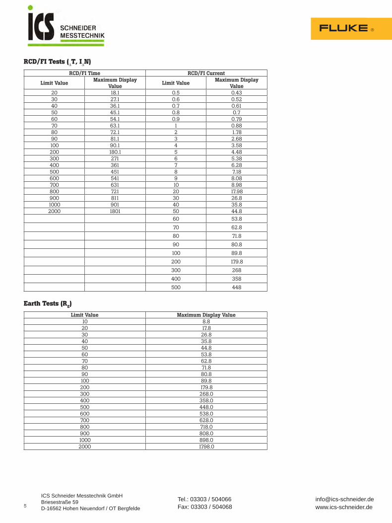
RCD/FI Tests (ΔT, IΔN)
Earth Tests (RE)
RCD/FI Time RCD/FI Current
Limit Value Maximum Display
Value Limit Value
Maximum Display Value
20 18.1 0.5 0.4330 27.1 0.6 0.5240 36.1 0.7 0.6150 45.1 0.8 0.760 54.1 0.9 0.7970 63.1 1 0.8880 72.1 2 1.7890 81.1 3 2.68100 90.1 4 3.58200 180.1 5 4.48300 271 6 5.38400 361 7 6.28500 451 8 7.18600 541 9 8.08700 631 10 8.98800 721 20 17.98900 811 30 26.81000 901 40 35.82000 1801 50 44.8
60 53.8
70 62.8
80 71.8
90 80.8
100 89.8
200 179.8
300 268
400 358
500 448
ICS Schneider Messtechnik GmbHBriesestraße 59D-16562 Hohen Neuendorf / OT Bergfelde
Tel.: 03303 / 504066Fax: 03303 / 504068
Limit Value Maximum Display Value 10 8.820 17.830 26.840 35.850 44.860 53.870 62.880 71.890 80.8100 89.8200 179.8300 268.0400 358.0500 448.0600 538.0700 628.0800 718.0900 808.01000 898.02000 1798.0
5
Range Resolution Accuracy
50Hz - 60Hz Input Impedance
Overload Protection
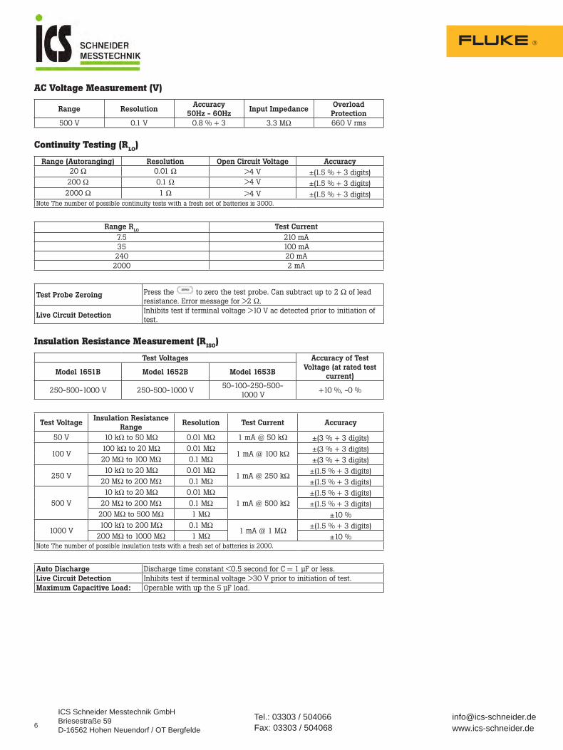
500V 0.1V 0.8%+3 3.3MΩ 660Vrms
AC Voltage Measurement (V)
Continuity Testing (RLO)
Insulation Resistance Measurement (RISO)
Range (Autoranging) Resolution Open Circuit Voltage Accuracy 20Ω 0.01Ω >4V ±(1.5%+3digits)200Ω 0.1Ω >4V ±(1.5%+3digits)2000Ω 1Ω >4V ±(1.5%+3digits)
NoteThenumberofpossiblecontinuitytestswithafreshsetofbatteriesis3000.
Range RLO Test Current 7.5 210mA35 100mA240 20mA2000 2mA
Test Probe Zeroing Pressthe tozerothetestprobe.Cansubtractupto2Ωofleadresistance.Errormessagefor>2Ω.
Live Circuit Detection Inhibitstestifterminalvoltage>10Vacdetectedpriortoinitiationoftest.
Test Voltages Accuracy of Test Voltage (at rated test
current) Model 1651B Model 1652B Model 1653B
250-500-1000V 250-500-1000V50-100-250-500-
1000V+10%,-0%
Test Voltage Insulation Resistance
Range Resolution Test Current Accuracy
50V 10kΩto50MΩ 0.01MΩ 1mA@50kΩ ±(3%+3digits)
100V100kΩto20MΩ 0.01MΩ
1mA@100kΩ ±(3%+3digits)20MΩto100MΩ 0.1MΩ ±(3%+3digits)
250V10kΩto20MΩ 0.01MΩ
1mA@250kΩ ±(1.5%+3digits)20MΩto200MΩ 0.1MΩ ±(1.5%+3digits)
500V10kΩto20MΩ 0.01MΩ
1mA@500kΩ±(1.5%+3digits)
20MΩto200MΩ 0.1MΩ ±(1.5%+3digits)200MΩto500MΩ 1MΩ ±10%
1000V100kΩto200MΩ 0.1MΩ
1mA@1MΩ ±(1.5%+3digits)200MΩto1000MΩ 1MΩ ±10%
NoteThenumberofpossibleinsulationtestswithafreshsetofbatteriesis2000.
ICS Schneider Messtechnik GmbHBriesestraße 59D-16562 Hohen Neuendorf / OT Bergfelde
Tel.: 03303 / 504066Fax: 03303 / 504068
Auto Discharge Dischargetimeconstant<0.5secondforC=1μForless.Live Circuit Detection Inhibitstestifterminalvoltage>30Vpriortoinitiationoftest.Maximum Capacitive Load: Operablewithupthe5μFload.
6

7
Loop and Line Impedance (ZI)No Trip and Hi Current Modes RCD/FI
Prospective Earth Fault Current Test (PSC/IK)
RCD Testing RCD Types Tested
Test Signals
Mains Input Voltage Range 100-500Vac(50/60Hz)Input Connection (soft key selection)
LoopImpedance:phasetoearthLineimpedance:phasetoneutral
Limit on Consecutive Tests Automaticshutdownwheninternalcomponentsaretoohot.ThereisalsoathermalshutdownforRCDtests.
Maximum Test Current @ 400 V 20Asinusoidalfor10msMaximum Test Current @ 230 V 12Asinusoidalfor10ms
Range Resolution Accuracy*
20Ω 0.01ΩNoTripmode:±(3%+6digits)HiCurrentmode:±(2%4digits)
200Ω 0.1ΩNoTripmode:±(3%)HiCurrentmode:±(2%)
2000Ω 1Ω ±6%**Notes* Validforresistanceofneutralcircuit<20 Ωanduptoasystemphaseangleof30°.Testleadsmustbezeroedbeforetesting.
** Validformainsvoltage>200V.
Computation ProspectiveEarthFaultCurrent(PEFC/IK)orProspectiveShortCircuitCurrent(PSC/IK)determinedbydividingmeasuredmainsvoltagebymeasuredloop(L-PE)resistanceorline(L-N)resistance,respectively.
Range 0to10kAor0to50kA(SeePower-OnOptionsearlierinthismanual)Resolution and Units Resolution Units
IK<1000A 1AIK>1000A 0.1kA
Accuracy Determinedbyaccuracyofloopresistanceandmainsvoltagemeasurements.
RCD Type* Model 1651B Model 1652B Model 1653B AC1 G2 √ √ √ AC S3 √ √ √ A4 G √ √
A S √ √ Notes1AC–RespondstoAC2G–General,nodelay3S–Timedelay4A–Respondstopulsedsignal*RCDtestinhibitedforV>265acRCDtestspermittedonlyifselectedcurrentxearthingresistanceis<50V.
ICS Schneider Messtechnik GmbHBriesestraße 59D-16562 Hohen Neuendorf / OT Bergfelde
Tel.: 03303 / 504066Fax: 03303 / 504068
RCD Type Test Signal Description
AC
Thewaveformisasinewavestartingatzerocrossing,polaritydeterminedbyphaseselection(0°phasestartswithlowtohighzerocrossing,180°phasestartswithhightolowzerocrossing).ThemagnitudeofthetestcurrentisIΔnxMultiplierforalltests.
A
Thewaveformisahalfwaverectifiedsinewavestartingatzero,polaritydeterminedbyphaseselection(0°phasestartswithlowtohighzerocrossing,180°phasestartswithhightolowzerocrossing).Themagnitudeofthetestcurrentis2.0xIΔn(rms)xMultiplierforalltestsforIΔn=0.01A.Themagnitudeofthetestcurrentis1.4xIΔn(rms)xMultiplierforalltestsforallotherIΔnratings.

8
Tripping Speed Test (ΔT)
Maximum Trip TimeTheRCD√symbolswitchesonwhentestingtheRCDtriptimeifthetriptimemeetsthefollowingconditions:
RCD/FI-Tripping Current Measurement/Ramp Test (IΔN)Models1652Band1653B
Earth Resistance Test (RE) Model1653BOnly.Thisproductisintendedtobeusedtomeasureinstallationsinprocessplants,industrialinstallations,andresidentialapplications.
Current Settings[1] Multiplier Current Accuracy 10–30–100–300–500–1000mA-VAR x1/2 +0%,-10%oftestcurrent10–30–100–300–500–1000mA-VAR x1 +10%,-0%10–30–100mA x5 +10%,-0%Note[1]1000mAtypeAConly.700mAmaximumtypeAinVARmode.
Current Multiplier *RCD Type Measurement Range
Trip Time Accuracy Europe UKx1/2 G 310ms 2000ms ±(1%Reading+1ms)x1/2 S 510ms 2000ms ±(1%Reading+1ms)x1 G 310ms 310ms ±(1%Reading+1ms)x1 S 510ms 510ms ±(1%Reading+1ms)x5 G 50ms 50ms ±(1%Reading+1ms)x5 S 160ms 160ms ±(1%Reading+1ms)Notes*G–General,nodelay*S–Timedelay
RCD I N Trip time limitsAC,G x1 Lessthan300msAC,G-Stype x1 Between130msand500msA x1 Lessthan300msA-Stype x1 Between130msand500msAC,G x5 Lessthan40msAC,G-Stype x5 Between50msand150msA x5 Lessthan40msA-Stype x5 Between50msand150ms
Current Range Step Size Dwell Time Measurement
Accuracy Type G Type S*30%to110%ofRCDratedcurrent
10%ofIΔN 300ms/step 500ms/step ±5%
Note30%to150%forTypeAIN>10mA,30%to210%forTypeAIN=10mASpecifiedtripcurrentrange:50%to100%forTypeAC,35%to140%forTypeA(>10mA),35%to200%forTypeA(≤10mA)
Range Resolution Accuracy 200Ω 0.1Ω ±(2%+5digits)2000Ω 1Ω ±(3.5%+10digits)
Range: RE + RPROBE Test Current 160Ω 50mA1600Ω 5mA16000Ω 500μA52000Ω 150μA
Frequency Output Voltage128Hz 25V
ICS Schneider Messtechnik GmbHBriesestraße 59D-16562 Hohen Neuendorf / OT Bergfelde
Tel.: 03303 / 504066Fax: 03303 / 504068
Live Circuit Detection Inhibitstestifterminalvoltage>10Vacisdetectedpriortostartoftest.

Phase Sequence IndicationModel1653BOnly
Mains Wiring TestIcons( )indicateifL-PEorL-Nterminalsarereversed.Instrumentoperationisinhib-itedandanerrorcodeisgeneratediftheinputvoltageisnotbetween100Vand500V.TheUKLoopandRCDtestsareinhibitediftheL-PEortheL-Nterminalsarereversed.
Operating Ranges and Uncertainties per EN 61557
Icon iconPhaseSequenceindicatorisactive.Display of Phase Sequence Displays“1-2-3”indigitaldisplayfieldforcorrect
sequence.Displays“3-2-1”forincorrectphase.Dashesinplaceofanumberindicateavaliddeterminationcouldnotbemade.
Mains Input Voltage Range (phase-to phase) 100to500V
Function Display Range EN 61557 Measurement
Range Operating Uncertainty
Nominal Values
VEN61557-1 0.0Vac–500Vac50Vac–500Vac±(2%+2dgt)
UN=230/400Vacf=50/60Hz
RLOEN61557-4 0.00Ω-2000Ω 0.2Ω-2000Ω±(10%+2dgt)
4.0Vdc<UQ>24VdcRLO≤2.00ΩIN≥200mA
RISOEN61557-2 0.00MΩ-1000MΩ1MΩ-200MΩ±(10%+2dgt)200MΩ-1000MΩ±(15%+2dgt)
UN=50/100/250/500/1000VdcIN=1.0mA
ZIEN61557-3
ZI0.00Ω-2000Ω
2Ω-1000Ω±(15%+2dgt)
UN=230/400Vacf=50/60HzIK=0A–10.0kA
ZI(NoTrip)0.00Ω-2000Ω
0.4Ω-2Ω±(15%+6dgt)
ZI(HiCurrent)0.00Ω-2000Ω
0.2Ω-2Ω±(10%+4dgt)
RE0.00Ω-2000Ω
10Ω-1000Ω±(10%+2dgt)
ΔT,IΔNEN61557-6
ΔT0.0ms–2000ms 25ms–2000ms±(10%+1dgt)
ΔT=10/30/100/300/500/1000mA
IΔN0.5mA–550mA0.5mA–550mA±(10%+1dgt)
IΔN=10/30/100/300/500mA
REEN61557-5 0.0Ω-2000Ω 10Ω-2000Ω±(10%+2dgt)
f=128Hz
PhaseEN61557-7 1:2:3
ICS Schneider Messtechnik GmbHBriesestraße 59D-16562 Hohen Neuendorf / OT Bergfelde
Tel.: 03303 / 504066Fax: 03303 / 504068

ICS Schneider Messtechnik GmbHBriesestraße 59D-16562 Hohen Neuendorf / OT Bergfelde
Tel.: 03303 / 504066Fax: 03303 / 504068
Influence Quantity
Volt
s
RLo
EN
615
57-4
RIS
O
EN
615
57-2
Z I
EN
615
57-3
ΔTE
N 6
1557
-6
IΔN
EN
615
57-6
RE
EN
615
57-5
E1-Position 0.00% 0.00% 0.00% 0.00% 0.00% 0.00% 0.00%E2-SupplyVoltage 0.50% 3.00% 3.00% 3.00% 3.00% 2.75% 2.25%E3-Temperature 0.50% 3.00% 3.00% 3.00% 3.00% 2.25% 2.75%E4-SeriesInterferencesVoltage - - - - - - 1.50%E5-Resistanceoftheprobesandauxiliaryearthelectrodes
- - - - - - 4.00%
E6.2-Systemphaseangle - - - 1.00% - - -E7-Systemfrequency 0.50% - - 2.50% - - 0.00%E8-Systemvoltage - - - 2.50% 2.50% 2.50% 0.00%E9-Harmonics - - - 2.00% - - -E10-D.C.Quantity - - - 2.50% - - -
Ordering information
1653B MultifunctionInstallationTester
1652B MultifunctionInstallationTester
1651B MultifunctionInstallationTester
Optional accessories•MTC1363MainsTestCord•MTC77MainsTestCord•ES165XEarthSpikeTestKit(1653only)•FVF-SC2FlukeViewSoftware(1653only)
Included with 1650B:•TP165XRemoteControlProbe(1652Band1653Bonly)•TL165/UKFusedtestleadset•TD07FPARTPtestcertificates(1651Bonly)•C1600HardCarryingCase•Mainstestcord•Zeroadapter•Paddedcarryingstrap•Quickreferenceguide•6AAbatteries
Operating Uncertainties per EN 61557 TheOperatingUncertaintyshowsthemaximumpossibleuncertaintywhenallinfluencefactorsE1-E10arecounted.
Volt
s
RLo
EN
615
57-4
RIS
O
EN
615
57-2
Z I
EN
615
57-3
ΔTE
N 6
1557
-6
IΔN
EN
615
57-6
RE
EN
615
57-5
IntrinsicUncertaintyA 0.80% 1.50% 10.00% 6.00% 1.00% 5.00% 3.50%