Embed Size (px)
Citation preview

The Joint Advanced Materials and Structures Center of Excellence
PASTE PASTE SCHOOL SCHOOL
LOGO LOGO HEREHERE
Fluid Ingression Damage Fluid Ingression Damage Mechanism in Composite Mechanism in Composite
Sandwich StructuresSandwich StructuresAllison Crockett, Wichita State UniversityAllison Crockett, Wichita State University
Hal Loken, ConsultantHal Loken, ConsultantJohn Tomblin, Wichita State UniversityJohn Tomblin, Wichita State University
July 17July 17--19, 200819, 2008

The Joint Advanced Materials and Structures Center of Excellence 2
FAA Sponsored Project Information
• Principal Investigators & Researchers– John Tomblin and Allison Crockett
• FAA Technical Monitor– Curt Davies
• Other FAA Personnel Involved– Larry Ilcewicz
• Industry Participation– Hal Loken, Consultant

The Joint Advanced Materials and Structures Center of Excellence 3
FAA Research Investigations
Research ObjectiveCharacterize the fluid
ingression phenomenon in composite sandwich
structures as well as to document the damage
mechanisms which allow the fluid ingression to propagate and potentially degrade the
structural performance

The Joint Advanced Materials and Structures Center of Excellence 4
Lessons Learned in 1980’s
• The trailing edge wedge on a 1970’s wide-body transport aircraft was constructed of the following:– Woven fabric composite facesheets, solid laminate
spar/attachment and aramid honeycomb core.• The prepreg resin level had been minimized to reduce
weight and the facesheet laminate had channels that directed water and Skydrol into the honeycomb core at the ply drop-offs.
• An increase in prepreg resin content solved this problem. • As new materials and methods come into use, we must
research application limits and define good practices.

The Joint Advanced Materials and Structures Center of Excellence 5
Lessons Learned in 1980’s
• One of the biggest problems for an airline operator is when large hailstones strike at a major airport.
• Composite sandwich fixed trailing edge panels are typically damaged by the hailstones
• If not sealed or repaired, these panels will later develop water ingression into the honeycomb core at the spot where each large hailstone struck.
• Research will establish a cost effective standard for hailstone resistance.

The Joint Advanced Materials and Structures Center of Excellence 6
What Industry Wants
• In May 2007, Fluid Ingression was highlighted at the Damage Tolerance Workshop in Amsterdam.
• As a result Industry wants to know some details about Fluid Ingression before other details.
• From our breakout session the following outcomes where determined to be the most important.
The Joint Advanced Materials and Structures Center of Excellence 7
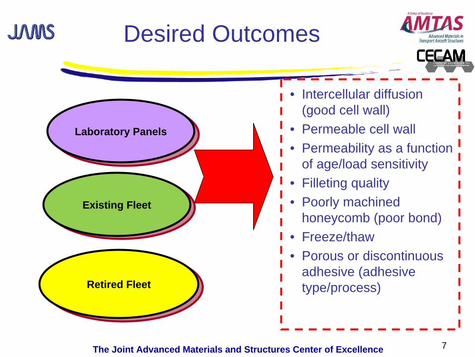
Laboratory PanelsLaboratory Panels
Desired Outcomes
• Intercellular diffusion (good cell wall)
• Permeable cell wall• Permeability as a function
of age/load sensitivity• Filleting quality• Poorly machined
honeycomb (poor bond)• Freeze/thaw• Porous or discontinuous
adhesive (adhesive type/process)Retired FleetRetired Fleet
Existing FleetExisting Fleet

The Joint Advanced Materials and Structures Center of Excellence 8
Laboratory PanelsLaboratory Panels
Desired Outcomes
• How resistant is core• Is fluid migration noticeable
without impact damage• Should there be a process
specification on core• Can foams be added to the
test matrix
Retired FleetRetired Fleet
Existing FleetExisting Fleet
The Joint Advanced Materials and Structures Center of Excellence
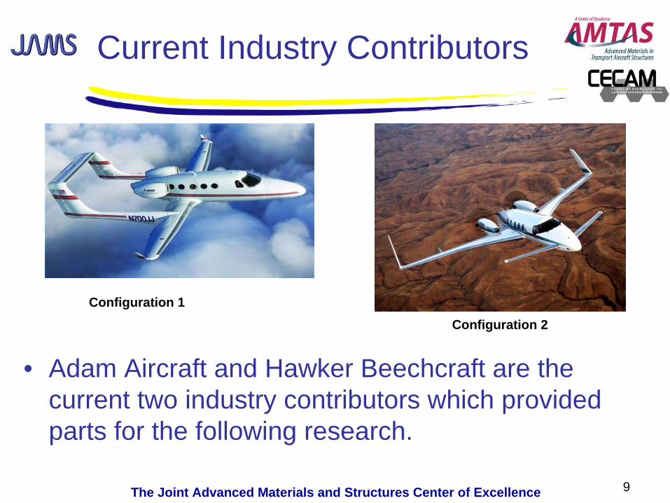
Current Industry Contributors
• Adam Aircraft and Hawker Beechcraft are the current two industry contributors which provided parts for the following research.
9
Configuration 1Configuration 2

The Joint Advanced Materials and Structures Center of Excellence 10
Terminology-Current Research
Fluid Ingression Fluid Ingression Damage ToleranceDamage Tolerance
Fluid Ingression Fluid Ingression Damage ResistanceDamage Resistance
Resistance to the propagation Resistance to the propagation of damage due to fluid of damage due to fluid
ingression and degradation of ingression and degradation of structural performancestructural performance
Material performance, design Material performance, design details and maintenance details and maintenance
practices which resist fluid practices which resist fluid ingression into the coreingression into the core
Proposed research program will focus on Proposed research program will focus on Fluid Ingression Damage ToleranceFluid Ingression Damage Tolerance

The Joint Advanced Materials and Structures Center of Excellence
Permeability of Honeycomb Core
• Fluid Migration Test (ASTM F1645-00)– 36” tall hydrostatic
column providing near- constant pressure within primary core cell wall.
– Fluid is applied to honeycomb cell through column for 24 hrs.
11

The Joint Advanced Materials and Structures Center of Excellence
Permeability of Honeycomb Core
• Test Set-up Parameters– Three samples from each
configuration were tested – Color dye/UV light was
used as a visual aide to see the fluid migrating.
– Deionized water was the initial fluid used
– Sample size was 3.0”length x 3.0” width
12
CONFIGURATION 2 PANEL
The Joint Advanced Materials and Structures Center of Excellence
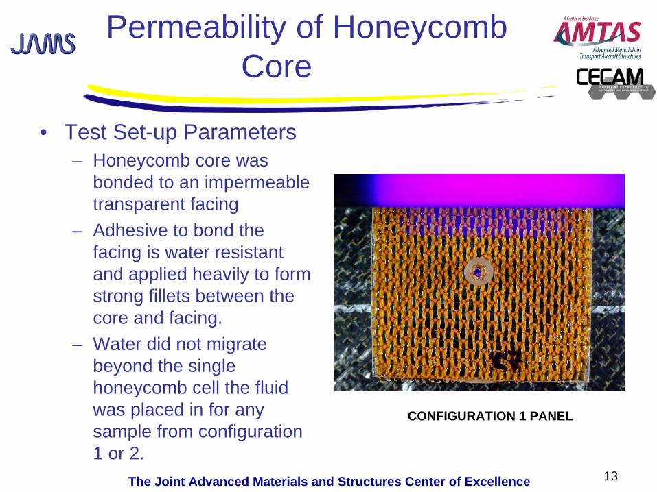
Permeability of Honeycomb Core
• Test Set-up Parameters– Honeycomb core was
bonded to an impermeable transparent facing
– Adhesive to bond the facing is water resistant and applied heavily to form strong fillets between the core and facing.
– Water did not migrate beyond the single honeycomb cell the fluid was placed in for any sample from configuration 1 or 2.
13
CONFIGURATION 1 PANEL

The Joint Advanced Materials and Structures Center of Excellence
Fluid Migration Testing continued…..
• Additional fluids were also used for the Water Migration Test using ASTM F1645-00
• Skydrol, JP-8, Hydraulic Fluid Royco 756– Skydrol made plexiglas
brittle causing it to fracture
14
The Joint Advanced Materials and Structures Center of Excellence
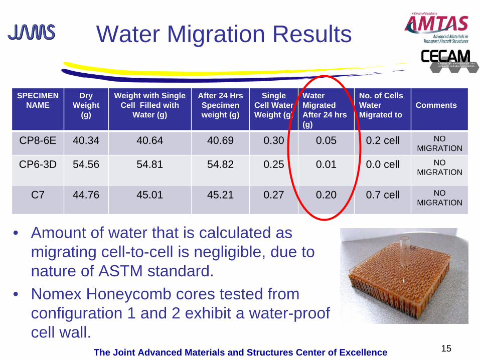
Water Migration Results
• Amount of water that is calculated as migrating cell-to-cell is negligible, due to nature of ASTM standard.
• Nomex Honeycomb cores tested from configuration 1 and 2 exhibit a water-proof cell wall.
SPECIMEN NAME
Dry Weight
(g)
Weight with Single Cell Filled with
Water (g)
After 24 Hrs Specimen weight (g)
Single Cell Water Weight (g)
Water Migrated After 24 hrs (g)
No. of Cells Water Migrated to
Comments
CP8-6E 40.34 40.64 40.69 0.30 0.05 0.2 cell NO MIGRATION
CP6-3D 54.56 54.81 54.82 0.25 0.01 0.0 cell NO MIGRATION
C7 44.76 45.01 45.21 0.27 0.20 0.7 cell NO MIGRATION
15
The Joint Advanced Materials and Structures Center of Excellence
Water Migration Results
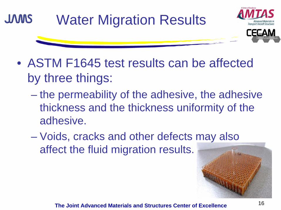
• ASTM F1645 test results can be affected by three things:– the permeability of the adhesive, the adhesive
thickness and the thickness uniformity of the adhesive.
– Voids, cracks and other defects may also affect the fluid migration results.
16

The Joint Advanced Materials and Structures Center of Excellence
• Consequently a more robust approach was taken so visibility of the cells and quality of the cell to facesheet bond was visible. The core was sliced in half as seen above, and a similar fluid test was repeated.
17
CP1B-3C BAG SIDE
TOOL SIDE
BAG SIDE
CP1B-3C TOOL SIDE
Permeability of Honeycomb Core

The Joint Advanced Materials and Structures Center of Excellence 18
Several Dry
Spots
Problem between Facesheet and Core contributing to Fluid migration
CONFIGURATION 2 PANEL

The Joint Advanced Materials and Structures Center of Excellence
Problem between Facesheet and Core contributing to Fluid migration
• Samples taken from the same Configuration 2 panel seen previously with dry spots.
• Three different fluids were added to one single cell.• Migration between cells occurred after fifteen minutes, in all
cases three cells filled with fluid immediately.• No Configuration 1 panels displayed dry spots and therefore
showed migration, half of the Configuration 2 panels tested showed migration.
19
SkydrolHydraulic Fluid Water
The Joint Advanced Materials and Structures Center of Excellence
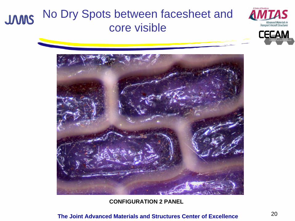
No Dry Spots between facesheet and core visible
20
CONFIGURATION 2 PANEL
The Joint Advanced Materials and Structures Center of Excellence
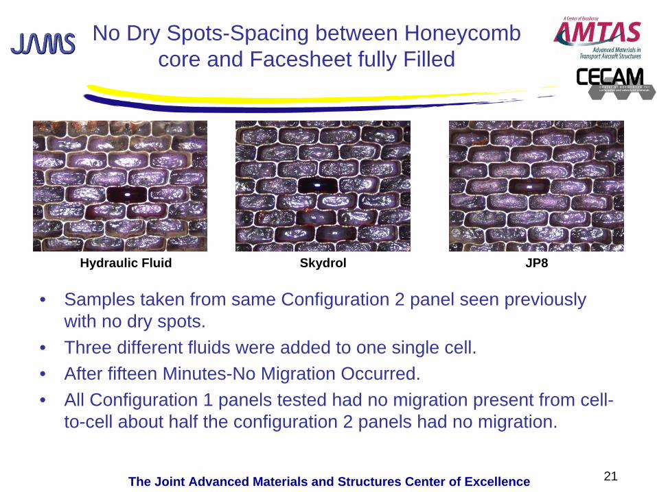
No Dry Spots-Spacing between Honeycomb core and Facesheet fully Filled
• Samples taken from same Configuration 2 panel seen previously with no dry spots.
• Three different fluids were added to one single cell. • After fifteen Minutes-No Migration Occurred.• All Configuration 1 panels tested had no migration present from cell-
to-cell about half the configuration 2 panels had no migration.
21
SkydrolHydraulic Fluid JP8

The Joint Advanced Materials and Structures Center of Excellence
Preliminary Results from Permeability Testing
• No evidence of fluid migration was present through undamaged Nomex Honeycomb Core Cell walls.
• With an adequate bond present between the facing and the core the Nomex Honeycomb core appears to be fluid resistant to the following:
– Deionized water, Skydrol, JP8 and Hydraulic fluid.
• Fluid will migrate through the spacing located between facesheet and the honeycomb core, a result of the facesheet not being completely filled with adhesive.
• This could be improved through manufacturing process improvements.
22

The Joint Advanced Materials and Structures Center of Excellence 23
Looking at Thermal Cycling Effects on Damage Panels
Simulated GAGcycling
Simulated GAGcycling
The Joint Advanced Materials and Structures Center of Excellence 24
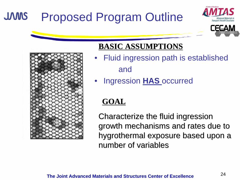
Proposed Program Outline
• Fluid ingression path is establishedand
• Ingression HAS occurred
GOALGOAL
Characterize the fluid ingression Characterize the fluid ingression growth mechanisms and rates due to growth mechanisms and rates due to hygrothermalhygrothermal exposure based upon a exposure based upon a number of variablesnumber of variables
BASIC ASSUMPTIONSBASIC ASSUMPTIONS

The Joint Advanced Materials and Structures Center of Excellence
Thermal Cycling Instructions
• After Impact Adam and Starship panels were soaked in water bath for 2 hours at 180F~ resembling worst case humidity condition.
• Panels were then cycled in in an environmental chamber from -65°F Dry to 180°F Dry.
• The samples were subject to 123 cycles prior to NDI inspection for damage growth.
25

The Joint Advanced Materials and Structures Center of Excellence
Impacting Configuration 2 Panels Panel CP4-8C
26
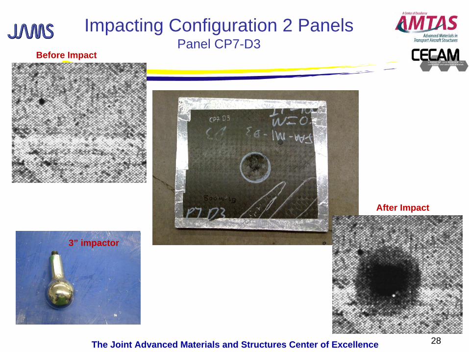
Before Impact
After Impact
3” Impactor
The Joint Advanced Materials and Structures Center of Excellence
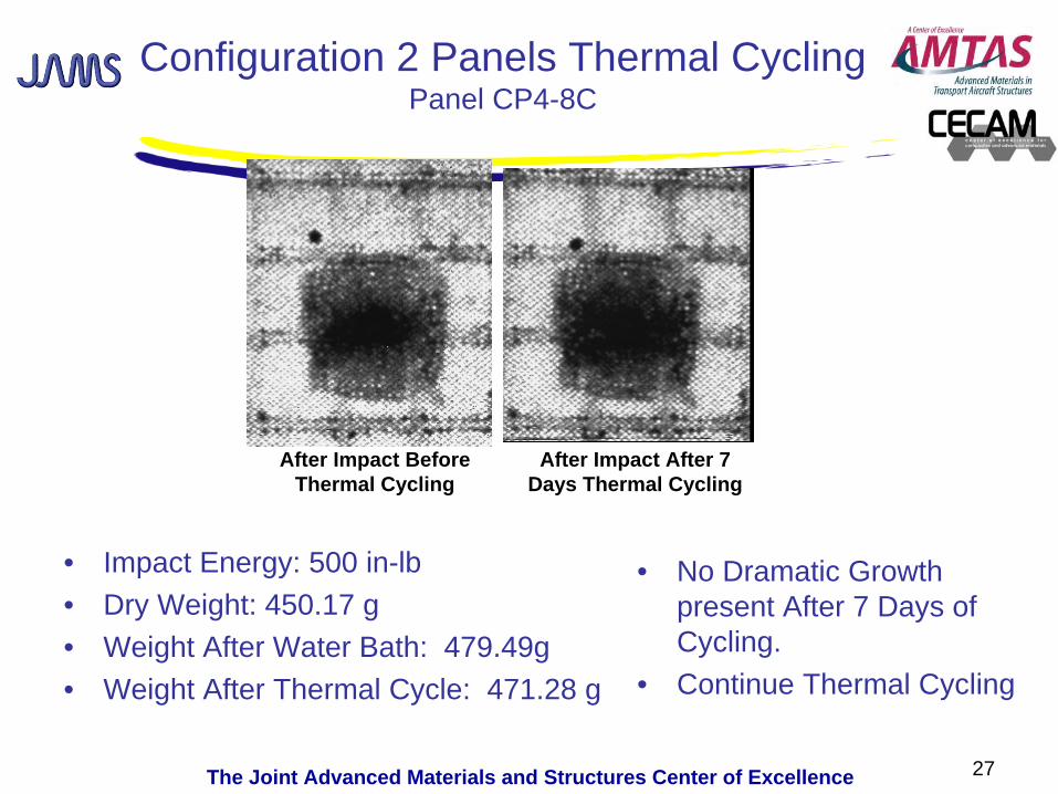
Configuration 2 Panels Thermal Cycling Panel CP4-8C
• Impact Energy: 500 in-lb• Dry Weight: 450.17 g• Weight After Water Bath: 479.49g• Weight After Thermal Cycle: 471.28 g
27
After Impact Before Thermal Cycling
After Impact After 7 Days Thermal Cycling
• No Dramatic Growth present After 7 Days of Cycling.
• Continue Thermal Cycling
The Joint Advanced Materials and Structures Center of Excellence
Impacting Configuration 2 Panels Panel CP7-D3
28
Before Impact
After Impact
3” impactor
The Joint Advanced Materials and Structures Center of Excellence
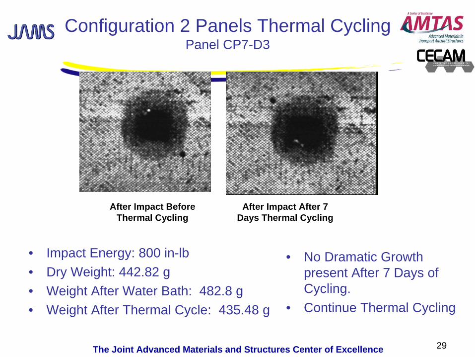
Configuration 2 Panels Thermal Cycling Panel CP7-D3
• Impact Energy: 800 in-lb• Dry Weight: 442.82 g• Weight After Water Bath: 482.8 g• Weight After Thermal Cycle: 435.48 g
29
After Impact Before Thermal Cycling
After Impact After 7 Days Thermal Cycling
• No Dramatic Growth present After 7 Days of Cycling.
• Continue Thermal Cycling

The Joint Advanced Materials and Structures Center of Excellence
Impacting Configuration 2 Panels Panel CP6-4D
30
Before ImpactAfter Impact

The Joint Advanced Materials and Structures Center of Excellence
Configuration 2 panels Thermal Cycling Panel CP6-4D
• Impact Energy: 1100 in-lb• Dry Weight: 531.61 g• Weight After Water Bath: 577.19 g• Weight After Thermal Cycle: 552.36 g
31
After Impact Before Thermal Cycling
After Impact After 7 Days Thermal Cycling
• No Dramatic Growth present After 7 Days of Cycling.
• Continue Thermal Cycling
The Joint Advanced Materials and Structures Center of Excellence
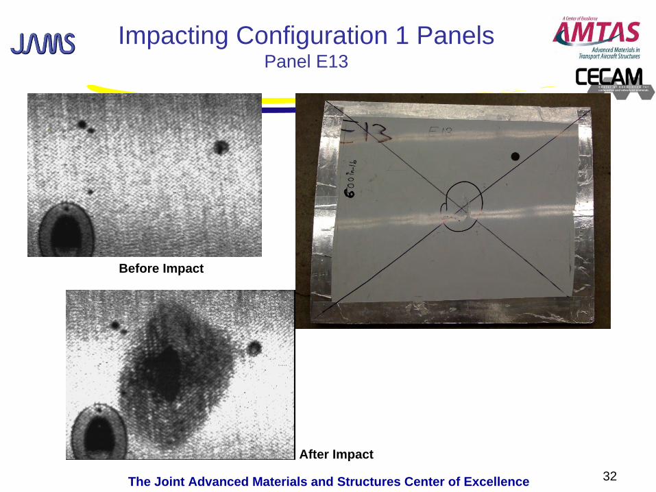
Impacting Configuration 1 Panels Panel E13
32
Before Impact
After Impact

The Joint Advanced Materials and Structures Center of Excellence
Configuration 1 Panel Thermal Cycling Panel E13
• Impact Energy: 600 in-lb• Dry Weight: 821.4 g• Weight After Water Bath: 834.6 g• Weight After Thermal Cycle: 822 g
33
After Impact Before Thermal Cycling
After Impact After 7 Days Thermal Cycling
• No Dramatic Growth present After 7 Days of Cycling.
• Continue Thermal Cycling

The Joint Advanced Materials and Structures Center of Excellence
Preliminary Thermal Cycling Results
• Continue with thermal cycling using the same environmental conditions while increasing the number of cycles completed before additional NDI is completed.
• Continued Cycle Plan 500, 1000, and 5000 cycles.
• This will help define what the growth rate is in damaged core with fluid present.
34
The Joint Advanced Materials and Structures Center of Excellence 35
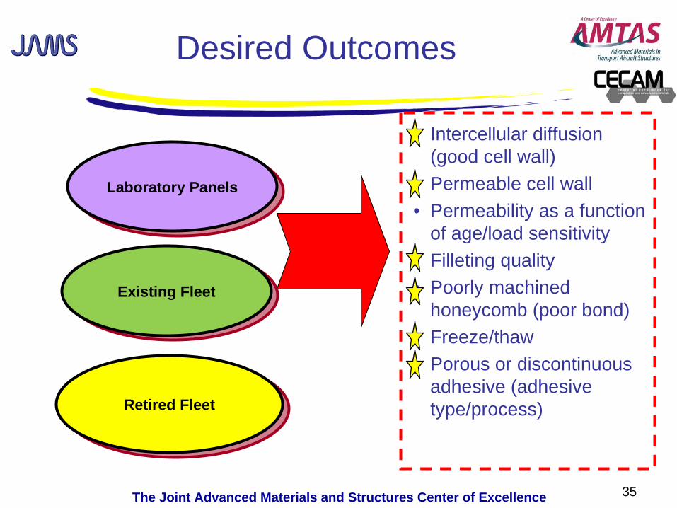
Laboratory PanelsLaboratory Panels
Desired Outcomes
• Intercellular diffusion (good cell wall)
• Permeable cell wall• Permeability as a function
of age/load sensitivity• Filleting quality• Poorly machined
honeycomb (poor bond)• Freeze/thaw• Porous or discontinuous
adhesive (adhesive type/process)Retired FleetRetired Fleet
Existing FleetExisting Fleet
The Joint Advanced Materials and Structures Center of Excellence 36
A Look Forward
• Benefit to Aviation– Characterize the damage mechanisms which allow the
fluid ingression to propagate and potentially degrade the structural performance
– Identify potential areas which should be monitored during routine aircraft service
– Provide awareness of the fluid ingression phenomenon as related to continued airworthiness
• Future needs– Provide guidance materials for design and maintenance of
composite sandwich structures

The Joint Advanced Materials and Structures Center of Excellence
PASTE PASTE SCHOOL SCHOOL
LOGO LOGO HEREHERE
Questions?Questions?
www.niar.wichita.e du