Embed Size (px)
Citation preview
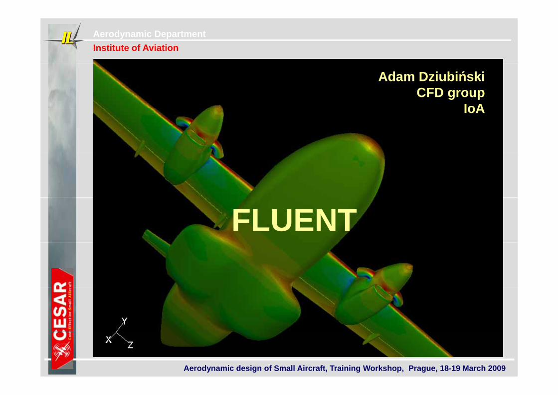
Aerodynamic DepartmentInstitute of Aviation
Adam DziubińskiCFD group
IoAIoA
FLUENT
Aerodynamic design of Small Aircraft, Training Workshop, Prague, 18-19 March 2009
Aerodynamic DepartmentInstitute of Aviation
Content
Fluent CFD softwareFluent CFD software1. Short description of main features of Fluent
Fluent CFD software
2. Examples of usage in CESAR
•Analysis of flow around an airfoil with a flap: VZLU + ILL4xx – validation with experimental data
•Analysis of flow aroundILM155 airfoil
– validation with experimental data
•Example of 3D modelling – evector aircraft
3. Examples of fluent usage in IoA CFD group recent works.
4. EOF
Aerodynamic design of Small Aircraft, Training Workshop, Prague, 18-19 March 2009
Aerodynamic DepartmentInstitute of Aviation
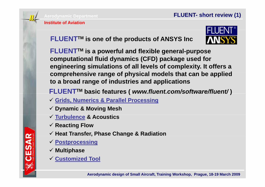
FLUENT- short review (1)
FLUENTTM is one of the products of ANSYS Inc
FLUENTTM is a powerful and flexible general purposeFLUENTTM is a powerful and flexible general-purpose computational fluid dynamics (CFD) package used for engineering simulations of all levels of complexity. It offers a
h i f h i l d l th t b li dcomprehensive range of physical models that can be applied to a broad range of industries and applicationsFLUENTTM basic features ( www.fluent.com/software/fluent/ )FLUENT basic features ( www.fluent.com/software/fluent/ ) Grids, Numerics & Parallel Processing Dynamic & Moving Mesh & Turbulence & Acoustics Reacting Flow Heat Transfer, Phase Change & Radiation, g Postprocessing Multiphase C t i d T l
Aerodynamic design of Small Aircraft, Training Workshop, Prague, 18-19 March 2009
Customized Tool
Aerodynamic DepartmentInstitute of Aviation
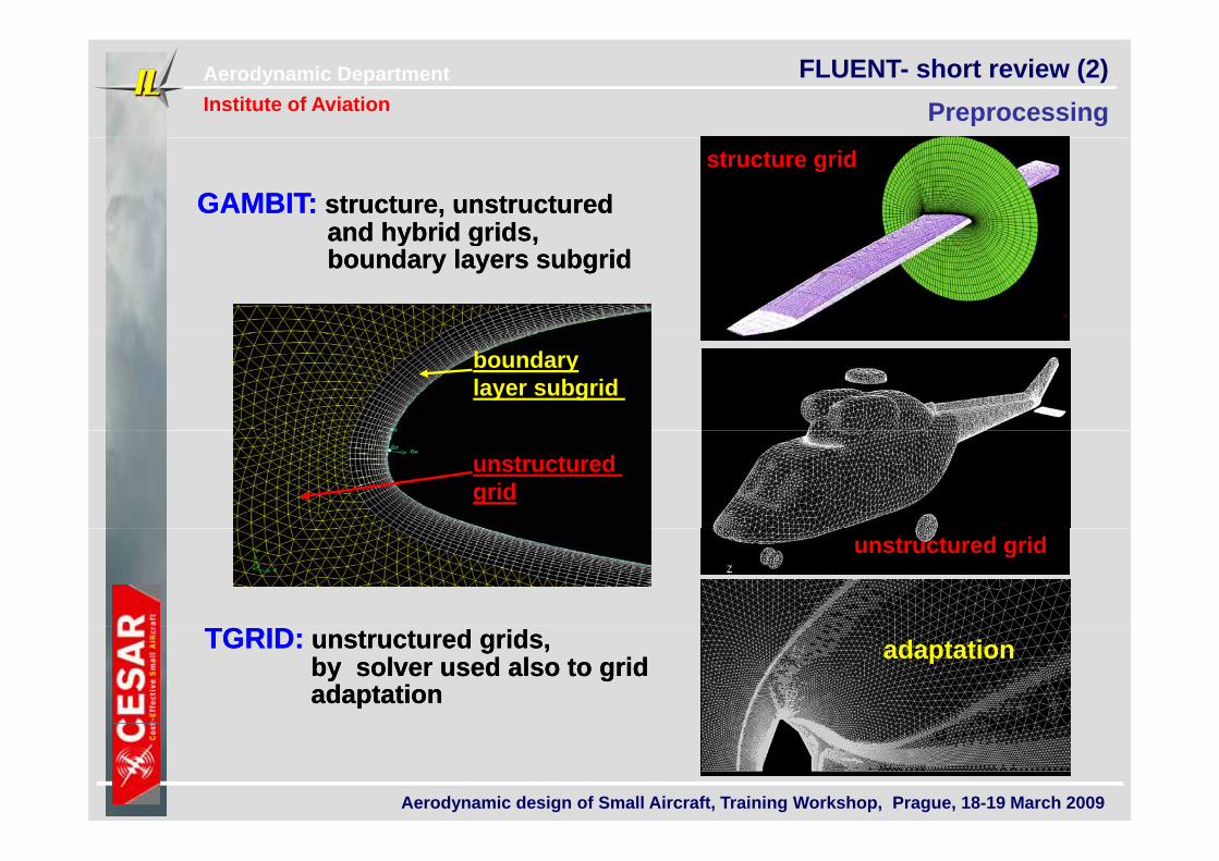
FLUENT- short review (2) Preprocessing
GAMBIT:GAMBIT: structure, unstructuredstructure, unstructuredand hybrid gridsand hybrid grids
structure grid
and hybrid grids,and hybrid grids,boundary layers subgridboundary layers subgrid
boundarylayer subgrid
unstructured grid
unstructured grid
TGRID:TGRID: unstructured grids,unstructured grids,by solver used also to gridby solver used also to gridadaptationadaptation
adaptation
Aerodynamic design of Small Aircraft, Training Workshop, Prague, 18-19 March 2009
Aerodynamic DepartmentInstitute of Aviation
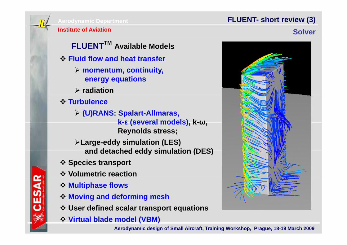
FLUENT- short review (3) Solver
Fluid flow and heat transferFLUENTTM Available Models
momentum, continuity, energy equations
radiation Turbulence
(U)RANS: Spalart-Allmaras, k-ε (several models) k-ωk-ε (several models), k-ω, Reynolds stress;
Large-eddy simulation (LES) and detached eddy simulation (DES)and detached eddy simulation (DES)
Species transport Volumetric reaction Multiphase flows Moving and deforming mesh U d fi d l t t ti
Aerodynamic design of Small Aircraft, Training Workshop, Prague, 18-19 March 2009
User defined scalar transport equations Virtual blade model (VBM)
Aerodynamic DepartmentInstitute of Aviation
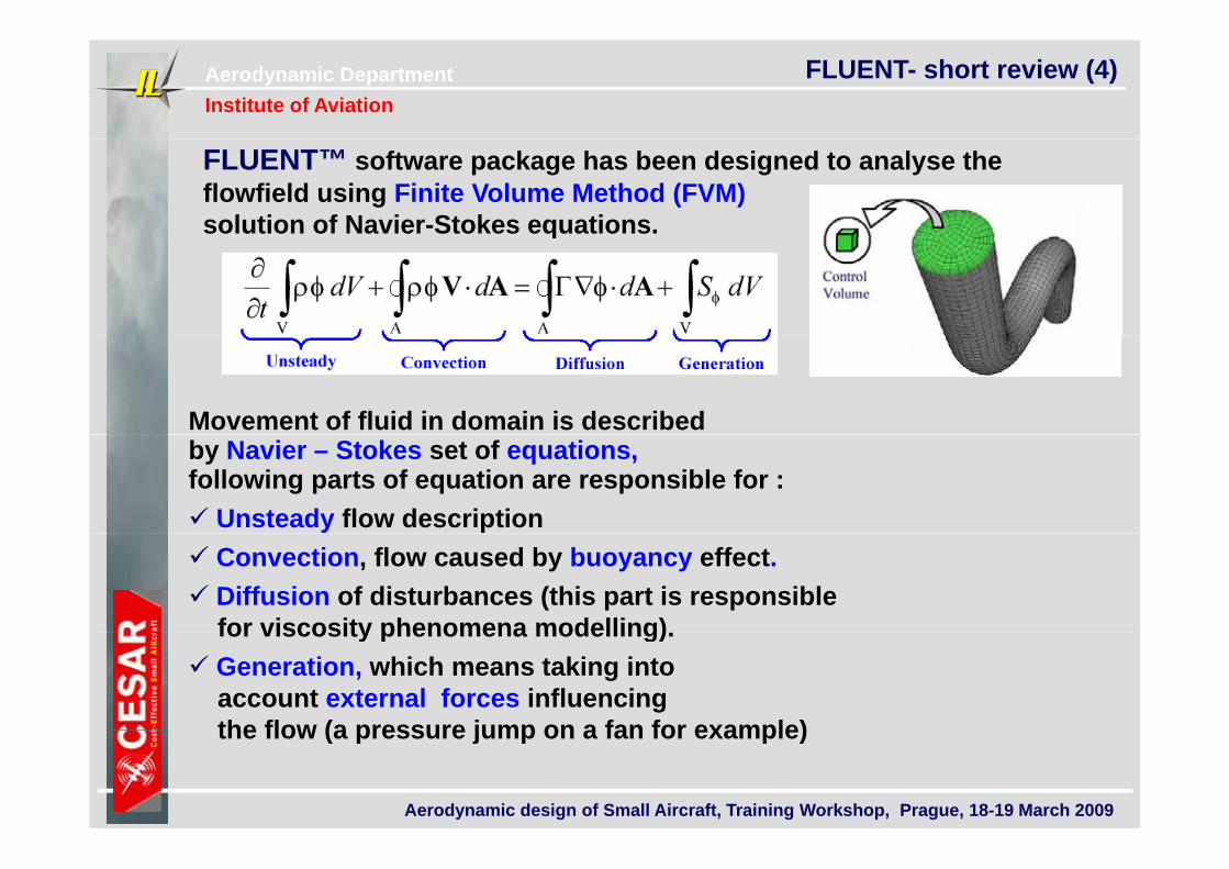
FLUENT- short review (4)
FLUENT™ software package has been designed to analyse the flowfield using Finite Volume Method (FVM)solution of Navier-Stokes equations.q
Movement of fluid in domain is described by Navier – Stokes set of equations,following parts of equation are responsible for : Unsteady flow description Convection, flow caused by buoyancy effect. Diffusion of disturbances (this part is responsible
for viscosity phenomena modelling)for viscosity phenomena modelling). Generation, which means taking into
account external forces influencing the flow (a pressure jump on a fan for example)
Aerodynamic design of Small Aircraft, Training Workshop, Prague, 18-19 March 2009
the flow (a pressure jump on a fan for example)
Aerodynamic DepartmentInstitute of Aviation
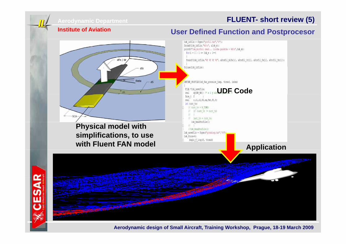
FLUENT- short review (5) User Defined Function and Postprocesor
UDF Code
Physical model with simplifications, to use with Fluent FAN model Applicationpp
Aerodynamic design of Small Aircraft, Training Workshop, Prague, 18-19 March 2009
Aerodynamic DepartmentInstitute of Aviation
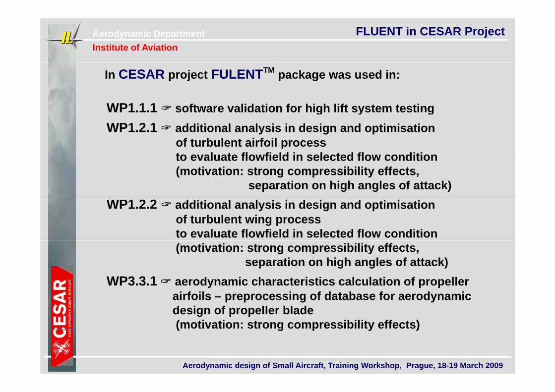
FLUENT in CESAR Project
In CESAR project FULENTTM package was used in:
WP1 1 1 software validation for high lift system testingWP1.1.1 software validation for high lift system testing WP1.2.1 additional analysis in design and optimisation
of turbulent airfoil process to evaluate flowfield in selected flow condition(motivation: strong compressibility effects,
separation on high angles of attack) WP1.2.2 additional analysis in design and optimisation
of turbulent wing process to evaluate flowfield in selected flow condition(motivation: strong compressibility effects,
separation on high angles of attack) WP3.3.1 aerodynamic characteristics calculation of propellerWP3.3.1 aerodynamic characteristics calculation of propeller
airfoils – preprocessing of database for aerodynamicdesign of propeller blade (motivation: strong compressibility effects)
Aerodynamic design of Small Aircraft, Training Workshop, Prague, 18-19 March 2009
( g p y )
Aerodynamic DepartmentInstitute of Aviation
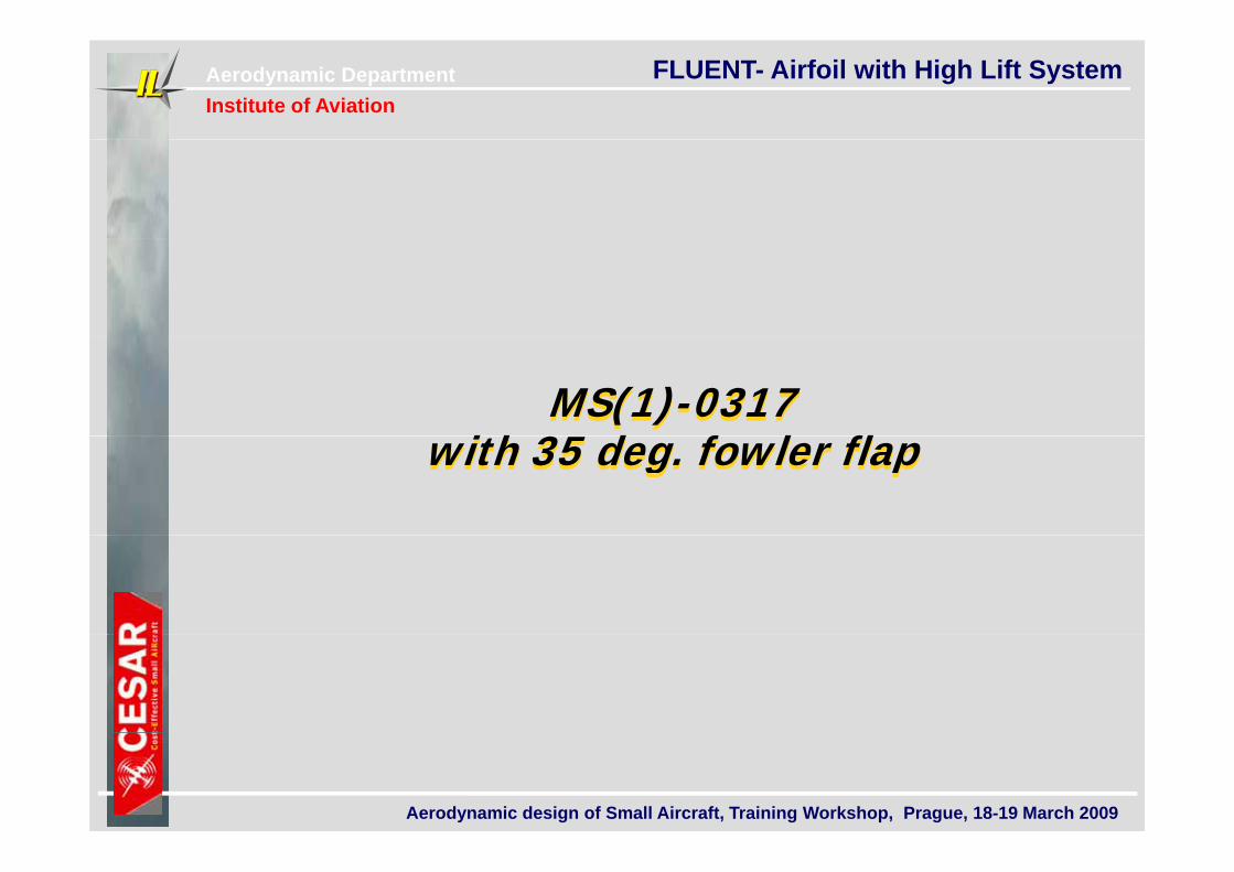
FLUENT- Airfoil with High Lift System
MS(1)-0317 MS(1)-0317 ith 35 d f l flwith 35 deg. fowler flapwith 35 deg. fowler flap
Aerodynamic design of Small Aircraft, Training Workshop, Prague, 18-19 March 2009
Aerodynamic DepartmentInstitute of Aviation
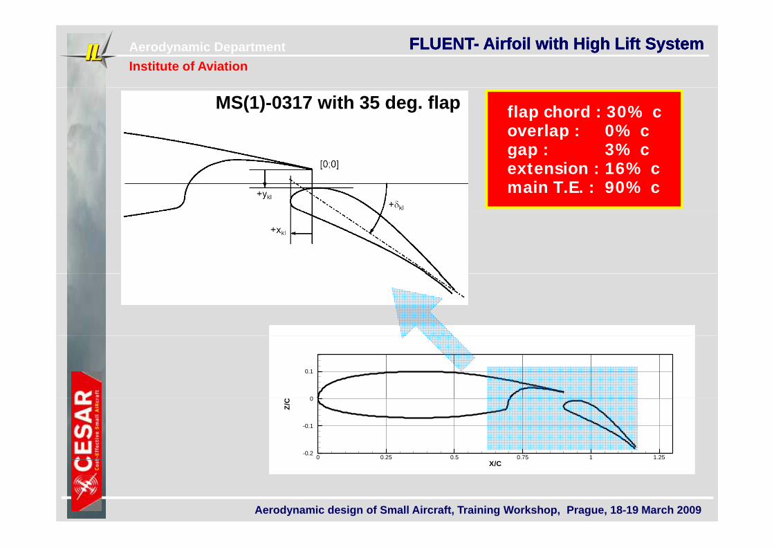
FLUENT- Airfoil with High Lift SystemFLUENT- Airfoil with High Lift SystemFLUENT- Airfoil with High Lift System
flap chord : 30% coverlap : 0% cgap : 3% c
MS(1)-0317 with 35 deg. flap
gap : 3% cextension : 16% cmain T.E. : 90% c
0
0.1
Z/C
0 0.25 0.5 0.75 1 1.25-0.2
-0.1
0
Aerodynamic design of Small Aircraft, Training Workshop, Prague, 18-19 March 2009
X/C
Aerodynamic DepartmentInstitute of Aviation
FLUENT- Airfoil with High Lift System
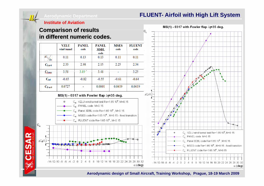
Comparison of resultsComparison of resultsComparison of results Comparison of results in different numeric codes. in different numeric codes.
Aerodynamic design of Small Aircraft, Training Workshop, Prague, 18-19 March 2009
Aerodynamic DepartmentInstitute of Aviation
FLUENT- Airfoil with High Lift System
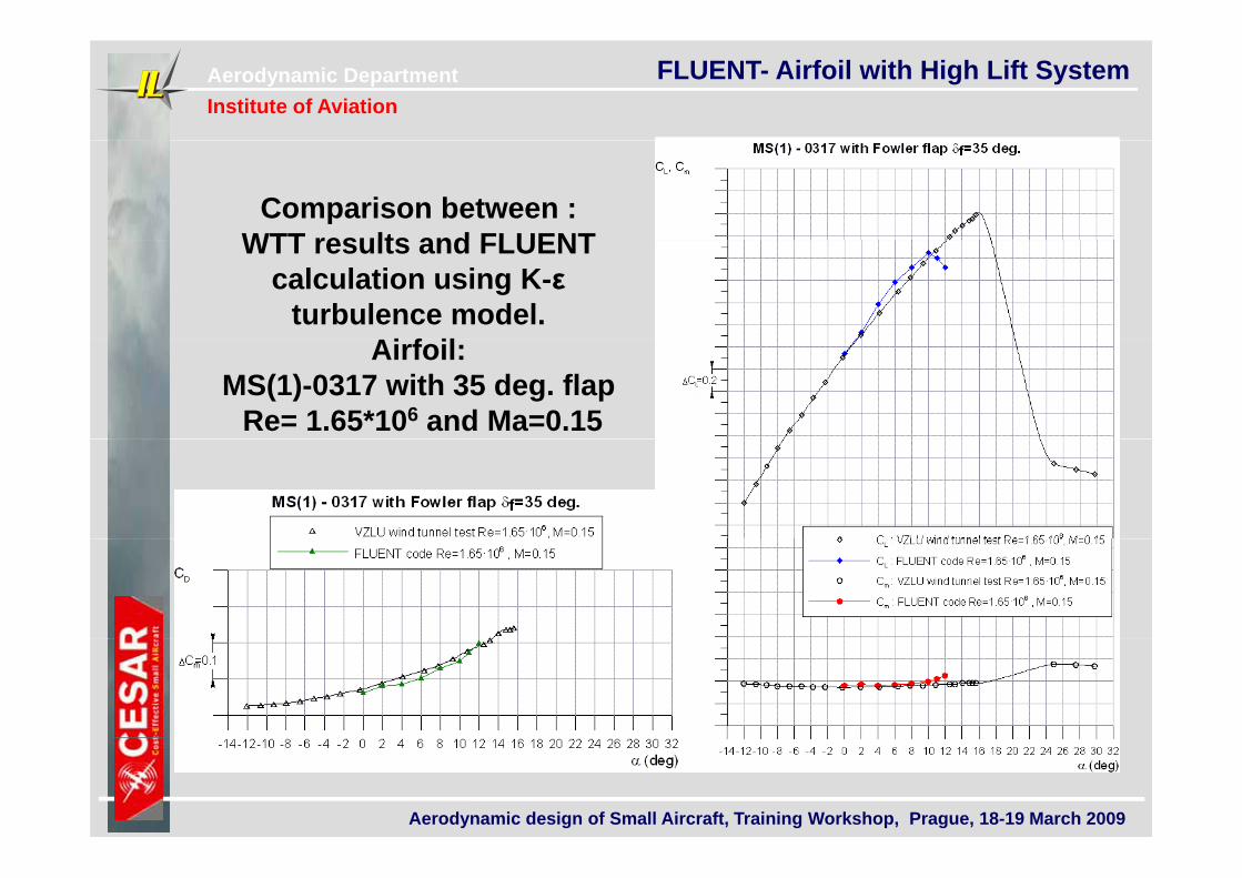
Comparison between : WTT results and FLUENTWTT results and FLUENT
calculation using K-ε turbulence model.
Ai f ilAirfoil:MS(1)-0317 with 35 deg. flap
Re= 1.65*106 and Ma=0.15
Aerodynamic design of Small Aircraft, Training Workshop, Prague, 18-19 March 2009
Aerodynamic DepartmentInstitute of Aviation
FLUENT- Airfoil with High Lift System
ILL417 ILL417 with 30 and 40 fowler flapwith 30 and 40 fowler flap
Aerodynamic design of Small Aircraft, Training Workshop, Prague, 18-19 March 2009
Aerodynamic DepartmentInstitute of Aviation
FLUENT- Airfoil with High Lift System
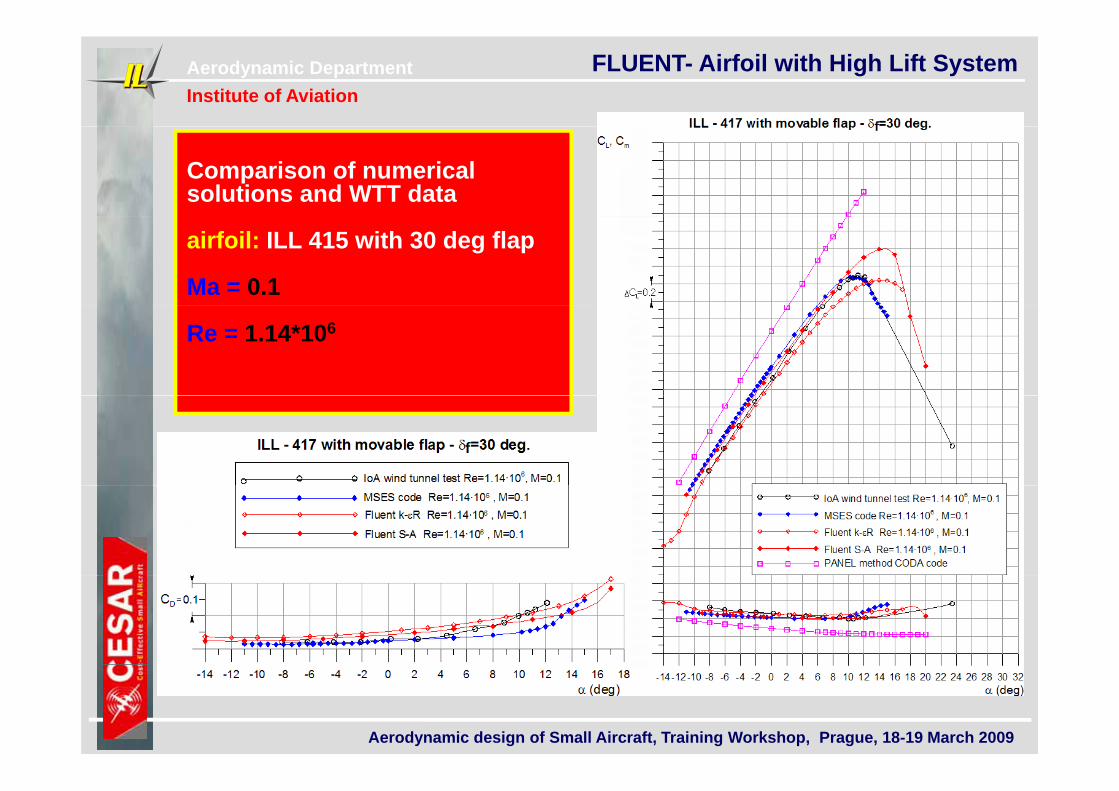
Comparison of numerical solutions and WTT data
airfoil: ILL 415 with 30 deg flap
Ma = 0.1
Re = 1.14*106
Aerodynamic design of Small Aircraft, Training Workshop, Prague, 18-19 March 2009
Aerodynamic DepartmentInstitute of Aviation
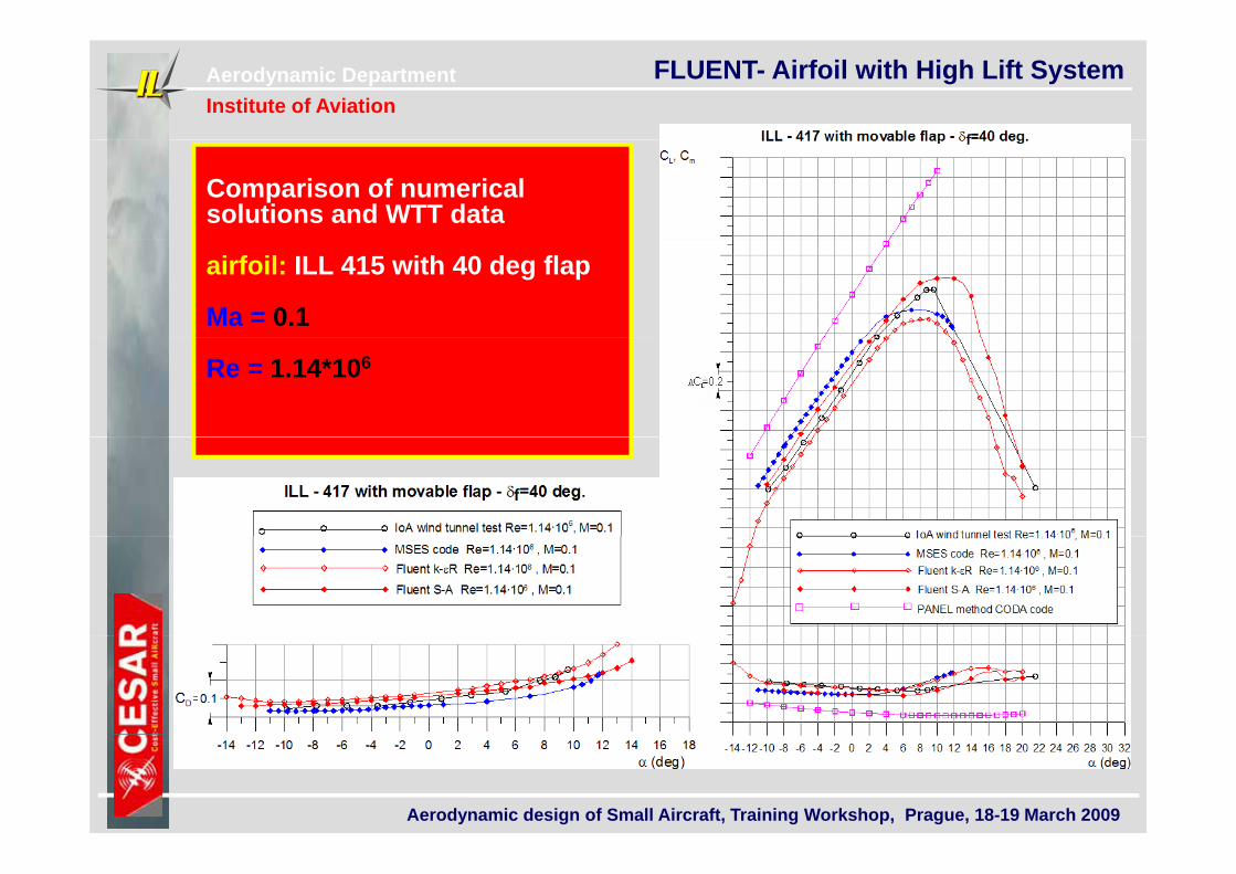
FLUENT- Airfoil with High Lift System
Comparison of numerical solutions and WTT data
airfoil: ILL 415 with 40 deg flap
Ma = 0.1
Re = 1.14*106
Aerodynamic design of Small Aircraft, Training Workshop, Prague, 18-19 March 2009
Aerodynamic DepartmentInstitute of Aviation
FLUENT- Airfoil with High Lift System
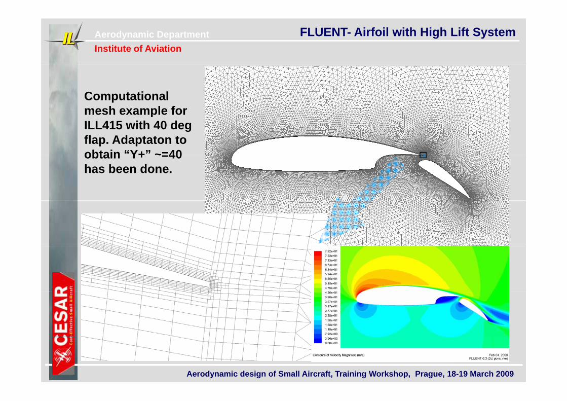
Computational mesh example formesh example for ILL415 with 40 deg flap. Adaptaton to obtain “Y+” ~=40obtain Y+ ~=40 has been done.
Aerodynamic design of Small Aircraft, Training Workshop, Prague, 18-19 March 2009
Aerodynamic DepartmentInstitute of Aviation
FLUENT- Airfoil with High Lift System
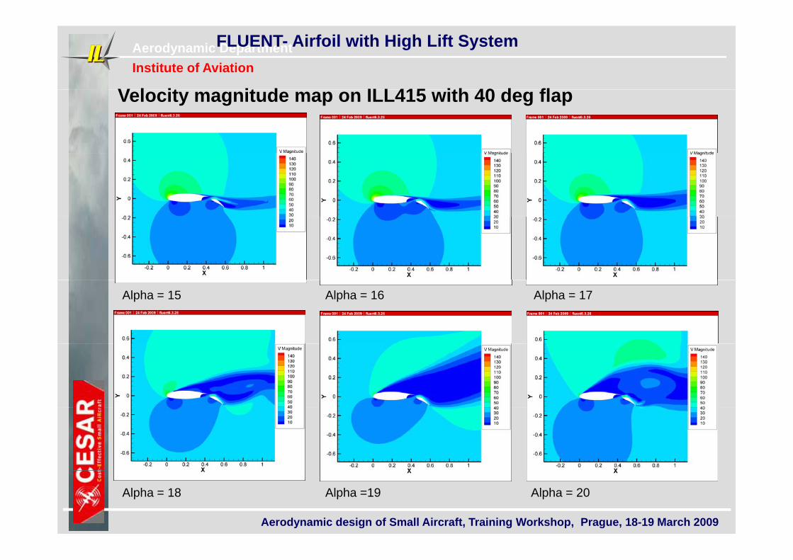
V l it it d ILL415 ith 40 d flVelocity magnitude map on ILL415 with 40 deg flap
Alpha = 15 Alpha = 16 Alpha = 17
Aerodynamic design of Small Aircraft, Training Workshop, Prague, 18-19 March 2009
Alpha = 20Alpha =19Alpha = 18
Aerodynamic DepartmentInstitute of Aviation
FLUENT- Airfoil with High Lift System
ILM-115 ILM-115 i f ilairfoilairfoil
Aerodynamic design of Small Aircraft, Training Workshop, Prague, 18-19 March 2009
Aerodynamic DepartmentInstitute of Aviation
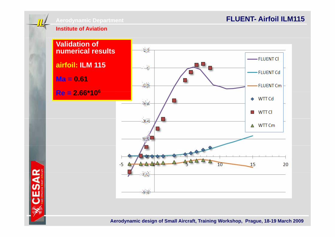
FLUENT- Airfoil ILM115
Validation of numerical results
airfoil: ILM 115airfoil: ILM 115
Ma = 0.61
Re = 2 66*106Re = 2.66*106
Aerodynamic design of Small Aircraft, Training Workshop, Prague, 18-19 March 2009
Aerodynamic DepartmentInstitute of Aviation
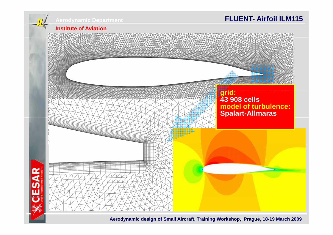
FLUENT- Airfoil ILM115
idgrid:43 908 cells model of turbulence:Spalart-Allmaras
Aerodynamic design of Small Aircraft, Training Workshop, Prague, 18-19 March 2009
Aerodynamic DepartmentInstitute of Aviation
FLUENT- Airfoil with High Lift System
AC-1 aircraftAC-1 aircraft
Aerodynamic design of Small Aircraft, Training Workshop, Prague, 18-19 March 2009
Aerodynamic DepartmentInstitute of Aviation
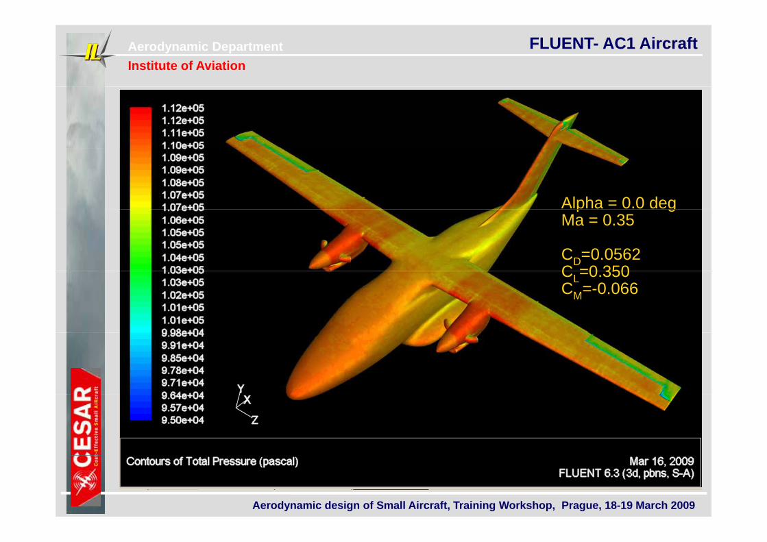
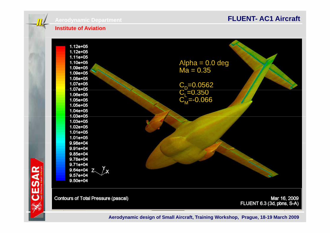
FLUENT- AC1 Aircraft
Alpha = 0.0 degp gMa = 0.35
CD=0.0562C =0 350CL=0.350CM=-0.066
Aerodynamic design of Small Aircraft, Training Workshop, Prague, 18-19 March 2009
Aerodynamic DepartmentInstitute of Aviation
FLUENT- AC1 Aircraft
Alpha = 0 0 degAlpha = 0.0 degMa = 0.35
CD=0.0562C 0 350CL=0.350CM=-0.066
Aerodynamic design of Small Aircraft, Training Workshop, Prague, 18-19 March 2009
Aerodynamic DepartmentInstitute of Aviation
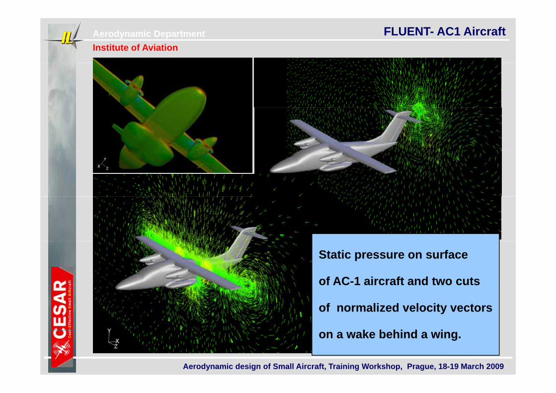
FLUENT- AC1 Aircraft
Static pressure on surface
of AC-1 aircraft and two cuts
of normalized velocity vectors
k b hi d i
Aerodynamic design of Small Aircraft, Training Workshop, Prague, 18-19 March 2009
on a wake behind a wing.
Aerodynamic DepartmentInstitute of Aviation
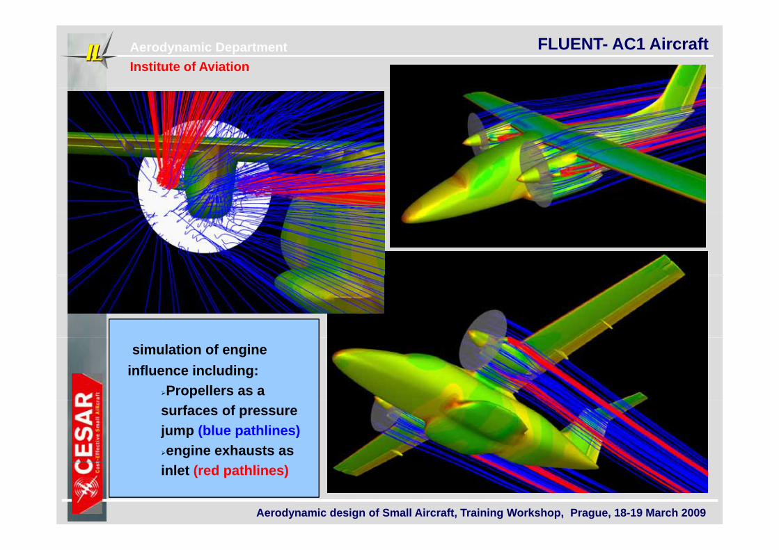
FLUENT- AC1 Aircraft
simulation of engine influence including:
Propellers as a surfaces of pressure jump (blue pathlines) engine exhausts as
Aerodynamic design of Small Aircraft, Training Workshop, Prague, 18-19 March 2009
inlet (red pathlines)
Aerodynamic DepartmentInstitute of Aviation
FLUENT- AC1 Aircraft
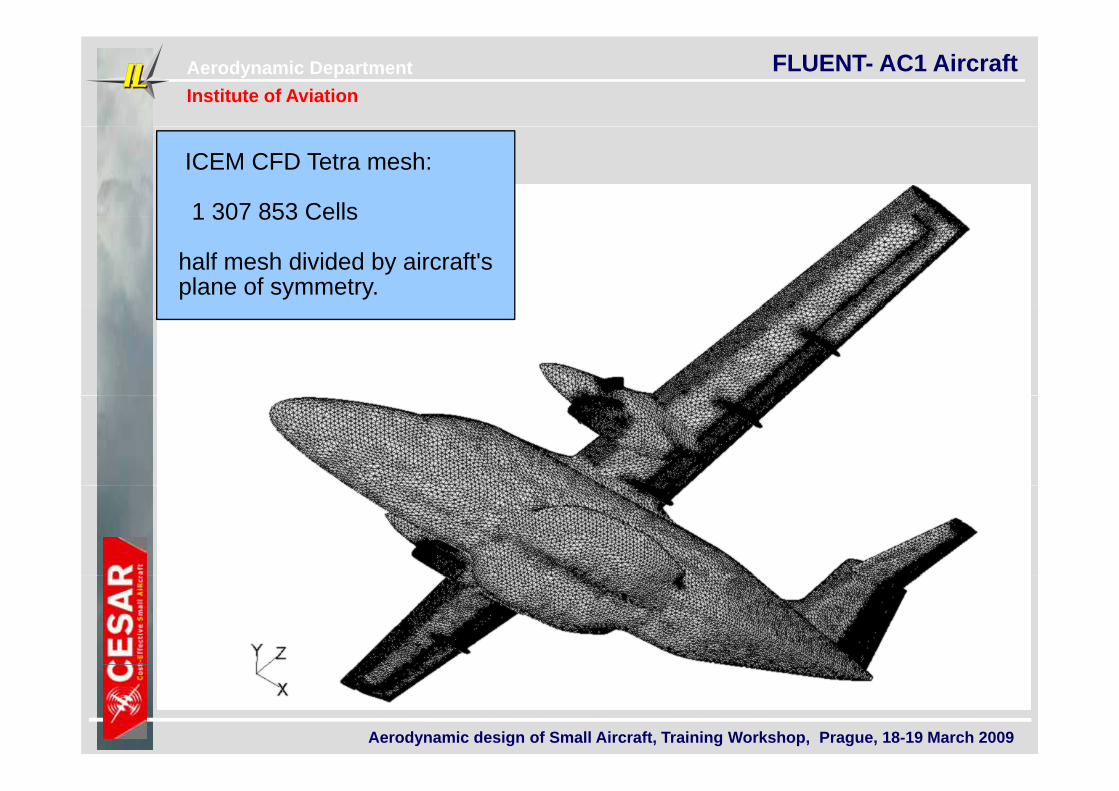
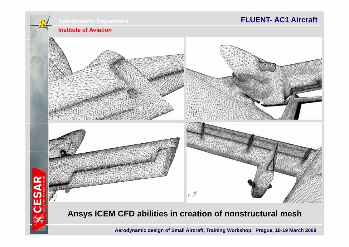
ICEM CFD Tetra mesh:
1 307 853 Cells1 307 853 Cells
half mesh divided by aircraft's plane of symmetry.
Aerodynamic design of Small Aircraft, Training Workshop, Prague, 18-19 March 2009
Aerodynamic DepartmentInstitute of Aviation
FLUENT- AC1 Aircraft
Aerodynamic design of Small Aircraft, Training Workshop, Prague, 18-19 March 2009
Ansys ICEM CFD abilities in creation of nonstructural mesh
Aerodynamic DepartmentInstitute of Aviation
FLUENT- Airfoil with High Lift System
IoA recent worksIoA recent works
Aerodynamic design of Small Aircraft, Training Workshop, Prague, 18-19 March 2009
Aerodynamic DepartmentInstitute of Aviation
FLUENT- Helicopter Simulation
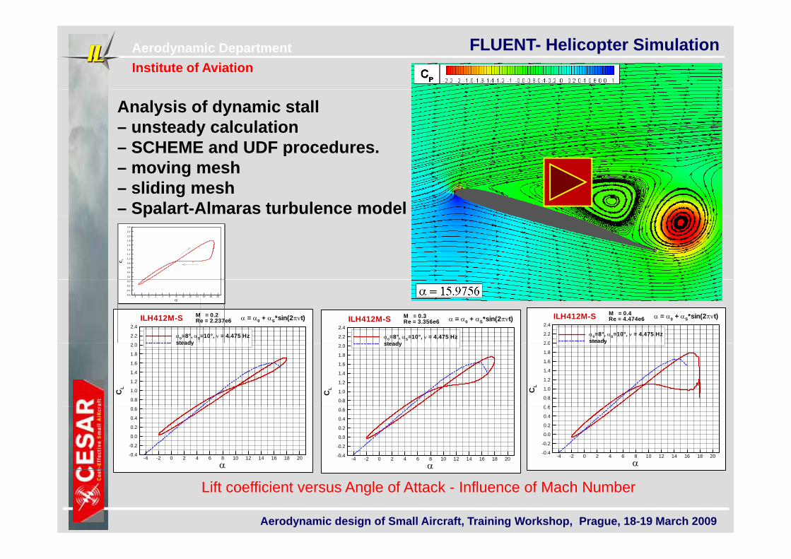
Analysis of dynamic stall– unsteady calculation– SCHEME and UDF procedures.SCHEME and UDF procedures.– moving mesh– sliding mesh– Spalart-Almaras turbulence modelp
CL
0.2
0.4
0.6
0.8
1.0
1.2
1.4
1.6
1.8
2.0
2.2
2.4
2.2
2.4
0=8°, S=10°, = 4.475 Hzsteady
M = 0.2Re = 2.237e6ILH412M-S = 0 + S*sin(2t)
2.2
2.4
0=8°, S=10°, = 4.475 Hzsteady
M = 0.3Re = 3.356e6ILH412M-S = 0 + S*sin(2t)
2 0
2.2
2.4
0=8°, S=10°, = 4.475 Hzsteady
M = 0.4Re = 4.474e6ILH412M-S = 0 + S*sin(2t)
-4 -2 0 2 4 6 8 10 12 14 16 18 20-0.6
-0.4
-0.2
0.0
CL
0.8
1.0
1.2
1.4
1.6
1.8
2.0 steady
CL
0.8
1.0
1.2
1.4
1.6
1.8
2.0 steady
CL
0 6
0.8
1.0
1.2
1.4
1.6
1.8
2.0 y
-4 -2 0 2 4 6 8 10 12 14 16 18 20
-0.4
-0.2
0.0
0.2
0.4
0.6
-4 -2 0 2 4 6 8 10 12 14 16 18 20
-0.4
-0.2
0.0
0.2
0.4
0.6
-4 -2 0 2 4 6 8 10 12 14 16 18 20
-0.4
-0.2
0.0
0.2
0.4
0.6
Aerodynamic design of Small Aircraft, Training Workshop, Prague, 18-19 March 2009
Lift coefficient versus Angle of Attack - Influence of Mach Number
Aerodynamic DepartmentInstitute of Aviation
FLUENT- Helicopter Simulation
Aerodynamic design of Small Aircraft, Training Workshop, Prague, 18-19 March 2009
Aerodynamic DepartmentInstitute of Aviation
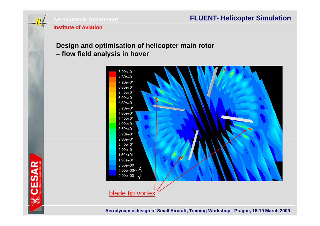
FLUENT- Helicopter Simulation
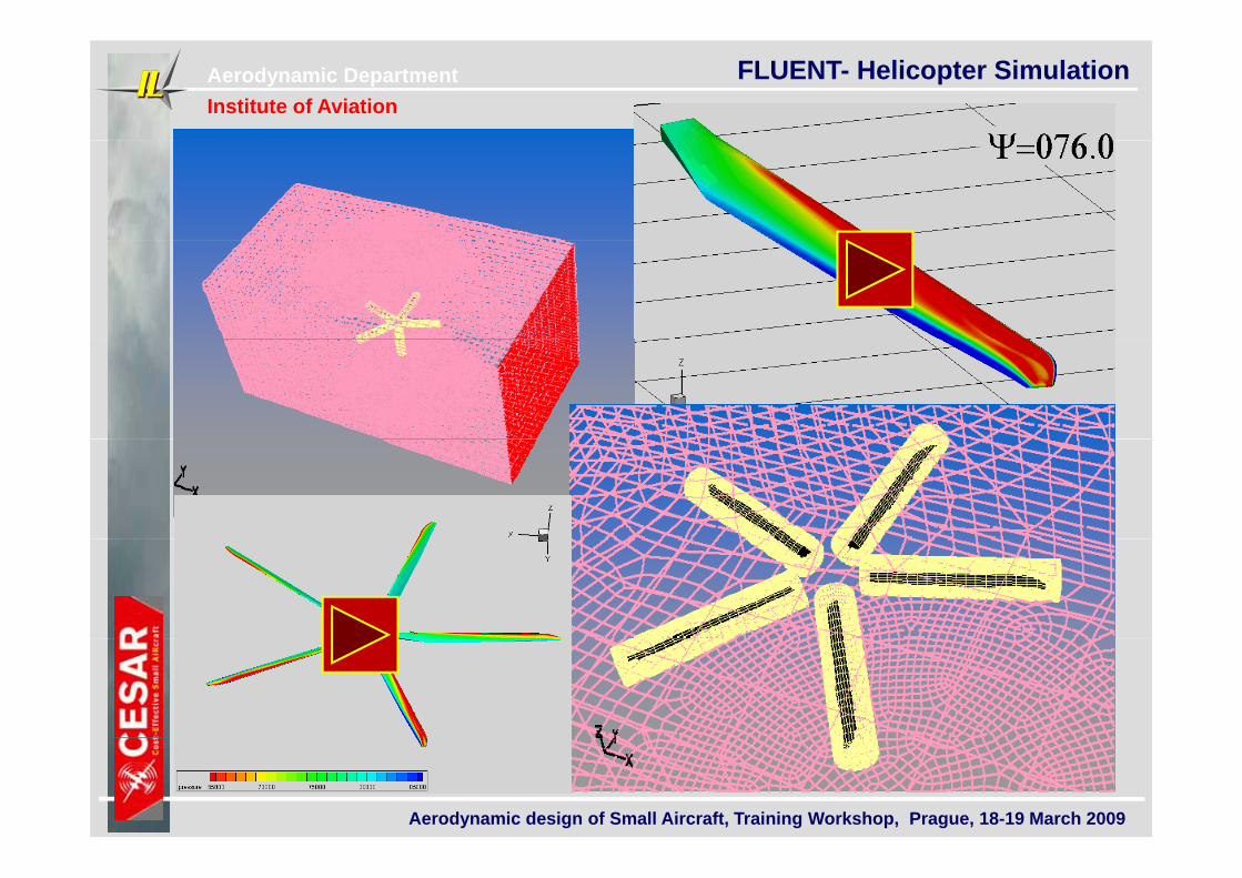
Design and optimisation of helicopter main rotor – flow field analysis in hover
Aerodynamic design of Small Aircraft, Training Workshop, Prague, 18-19 March 2009
blade tip vortex
Aerodynamic DepartmentInstitute of Aviation
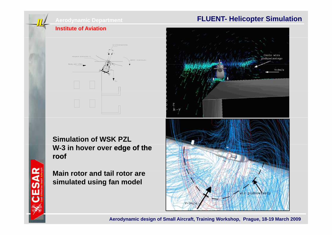
FLUENT- Helicopter Simulation
Simulation of WSK PZLW-3 in hover over edge of the edge of the roofroof
M i t d t il tMain rotor and tail rotor are simulated using fan model
Aerodynamic design of Small Aircraft, Training Workshop, Prague, 18-19 March 2009
Aerodynamic DepartmentInstitute of Aviation
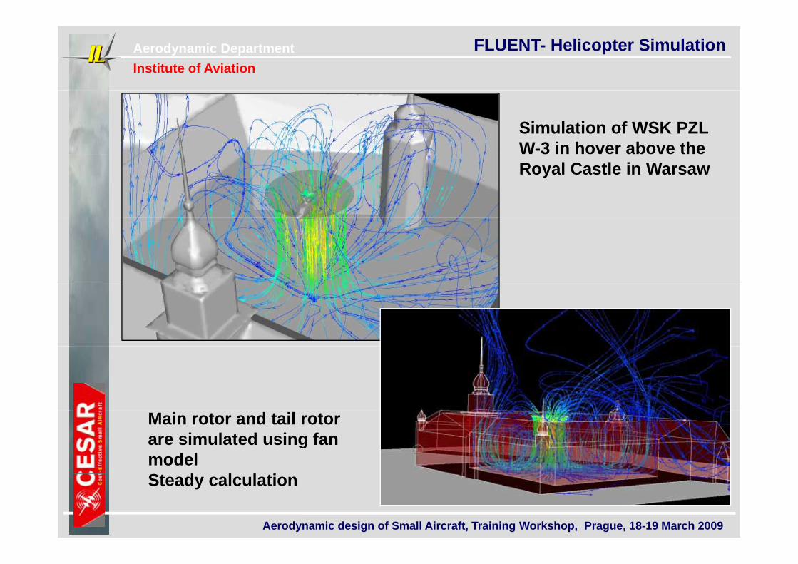
FLUENT- Helicopter Simulation
Simulation of WSK PZLW-3 in hover above the W 3 in hover above the Royal Castle in Warsaw
Main rotor and tail rotor are simulated using fan modelSt d l l ti
Aerodynamic design of Small Aircraft, Training Workshop, Prague, 18-19 March 2009
Steady calculation
Aerodynamic DepartmentInstitute of Aviation
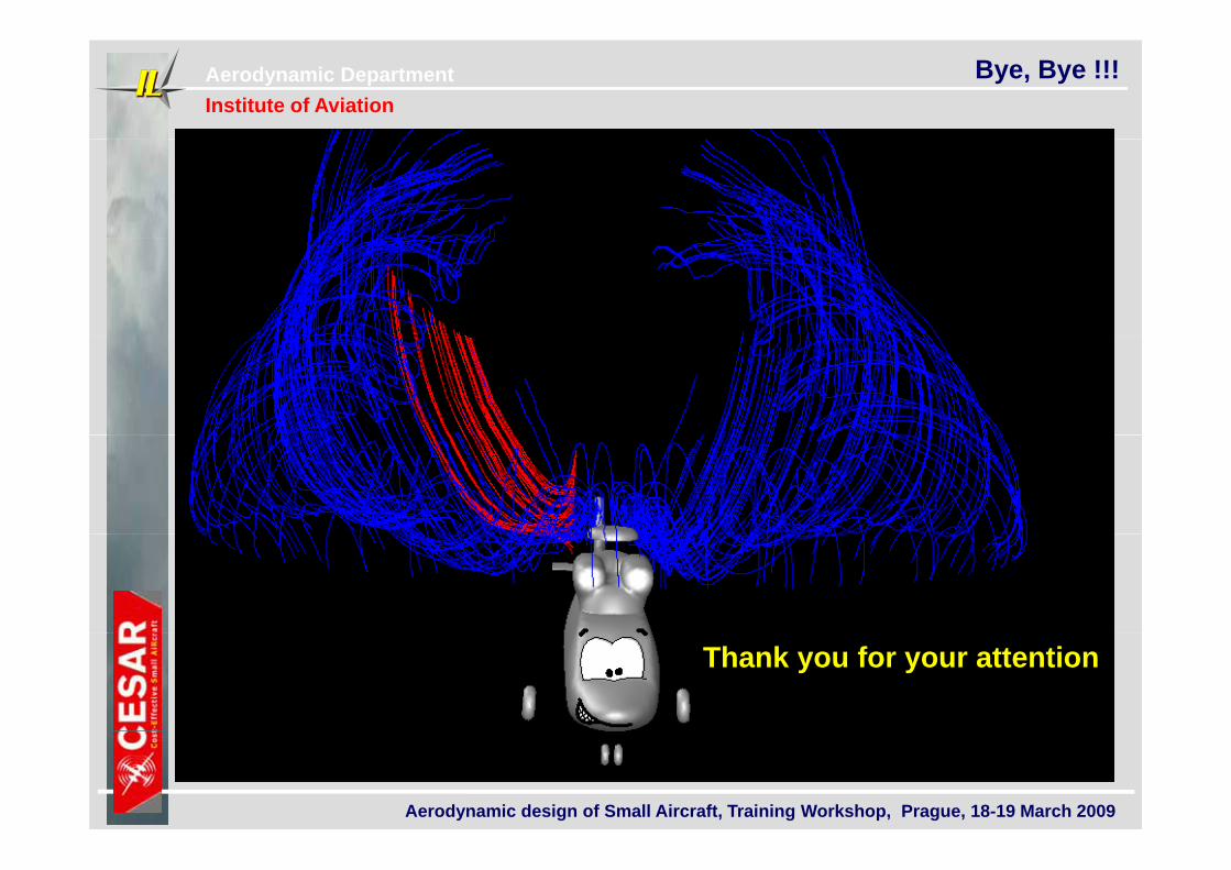
Bye, Bye !!!
Thank you for your attention
Aerodynamic design of Small Aircraft, Training Workshop, Prague, 18-19 March 2009