Embed Size (px)
Citation preview

6
H
1/4 H min
(F)LS (ES, IA, MV, PX), FCR3-phase asynchronous TEFV brake motors
Installation
2908 en - 2013.03 / u
This manual is to be given
to the end useren

8
INSTALLATION
(F)LS (ES, IA, MV, PX), FCR3-phase asynchronous TEFV brake motors
2908 en - 2013.03 / uLEROY-SOMER
This document complements the general instructions ref. 1889 (recommendations), ref. 3770 (LS), ref. 4850 (LSES LS2/IE2),ref. 3255, 3385 (ATEX specific recommendations) and the specific instructions ref. 5025 (FCR brake motor maintenance).
FCR brake motors are monobloc units consisting of an induction motor and a failsafe brake system (safety brake).This motor benefits from the experience of one of the largest manufacturers in the world, using state-of-theart technology in automation, specially selected materials, rigorous quality control. As a result, the regulatory authorities have awarded our motor factories the ISO 9001 - Edition 2008 international certificate.EC conformity: motors conform to the harmonized standard EN 60034 (IEC 34) therefore with the low voltage Directive 2006/95/EC and as EC marked.The noise level of the machines, measured under normal conditions, conforms to the requirements of the standard (IEC 34-9).
IMPORTANTThese symbols appear in this document whenever it is important to take special precautions during installation, operation, servicing or maintenance of the motors.
The specifications, instructions and descriptions are for standard operation. They do not take account of structural variants or special adaptations. Failure to comply with these recommendations may lead to premature deterioration of the motor and voiding of the manufacturer’s guarantee.Check motor compatibility with its environment before installation and over its entire operating lifetime.
Electric brake motors are industrial products. Therefore, they must only be installed by qualified experienced and authorised personnel. The safety of people, animals and goods should be ensured when fitting the motors into machines (please refer to current standards).Particular attention should be given to the equipotential ground or earthing connections.Workforce safety: protect all rotating devices before power-up. If running a motor without fitting a coupling device, carefully immobilise the key in its location. All measures must be taken to ensure protection from the risks presented by rotating parts (sleeve, pulley, belt, etc.). Beware of backdriving when the motor is switched off, it is necessary to take appropriate precautions: pumps, install a non-return valve, for example.
The following precautions must be taken before working on any stopped device:• mains voltage disconnected and no residual voltage present• careful study of the causes of the stoppage (blocked transmission - loss of phase - cut-out due to thermal protection - lack of lubrication, etc.)
PREFACE: ATEX TRAINING Specific ATEX marking ➉0080 : INERIS identification number (Notified Organisation) T (max) : Maximum surface temperature: 125°C for example
: Specific marking Db, Dc : Protection level of equipmentII 2D Ex tb IIIC : Group II, category 2, Dust or: Attestation n° : Type test attestation n° issued by INERISII 3D Ex tc IIIB : Group II, category 3, non-conducting Dust (réf. 3255 instructions) Those persons required to work on electrical installations and equipment in zones where there is a risk of explosion must be specially trained in the necessary skills.In effect, they must be familiar not only with the electrical risks, but also with those that are due to the chemical properties and physical characteristics of products used in the installation (gas, vapour, dust), as well as the environment in which the equipment operates. These elements dictate the risk of fire and explosion.In particular, they must be informed and aware of the specific safety reasons and requirements in order to adhere to them.For example:- do not open when powered up, - do not manoeuvre when on load,- do not open when powered up in atmospheres - wait several minutes before opening, containing explosive dust, - replace the seals tightly to ensure watertightness.- do not separate when powered up,
CONTENTS1 - RECEIPT ............................................................................................................................................................................................... 9
1.1 - Identification ................................................................................................................................................................................... 91.2 - Storage .......................................................................................................................................................................................... 9
2 - RECOMMENDATIONS ......................................................................................................................................................................... 92.1 - Commissioning .............................................................................................................................................................................. 92.2 - Mechanical installation ................................................................................................................................................................... 92.3 - Electrical connection ...................................................................................................................................................................... 92.4 - Terminal box and cable gland for FCR brake motors .................................................................................................................... 10
2.4.1 - Terminal box for FCR brake motors ....................................................................................................................................... 102.4.2 - Tightening capacity and torque of cable gland for FCR brake motors .................................................................................... 10
2.5 - Wiring diagrams ...................................................................................................................................................................... 10-112.6 - Electrical advices ......................................................................................................................................................................... 12
NOTE : Leroy-Somer reserves the right to modify its product characteristics at any time to incorporate the latest technological developments. The information contained in this document may therefore be changed without prior warning.Copyright 2008 : MOTEURS LEROY-SOMER. This document is the property of MOTEURS LEROY-SOMER. It cannot be reproduced in any form without prior authorisation. All brand names are registered trademarks.

9
INSTALLATION
(F)LS (ES, IA, MV, PX), FCR3-phase asynchronous TEFV brake motors
2908 en - 2013.03 / uLEROY-SOMER
en
1 - RECEIPTCheck the state of the brake motor - should the motor or even the packaging be damaged in any way, inform the carrier.Check that the brake motor conforms with the order specifications (mounting arrangement, information on the identification plate).
1.1 - Identification
3 (F)LSPX90L T
S1IP65
V230400
5.83.3
50
INERIS 03 ATEX 0012 XII 2D Ex tb IIIC T125°C Db
1.5 0.821430Hz min-1 k W A
6331
01B
IK08 Ta40°C clFcos ϕ
N° 12345 6789/001FCR J02 IP 65
0080F-16915 ANGOULEME
18020 NmMf UN VDC
6
10
8
10
43
1
2
7
9
5
Following details indicated on name plate:
Motor series, frame size ➀Brake type (FCR J02) ➁Speed rotation (min-1) ➂Rated power (kW) ➃Motor voltage (V) ➄Manufacturing number ➅Mf Braking torque (N.m) ➆UN Brake coil voltage (V) ➇Duty cycle (S1) ➈Specific ATEX marking (p. 2) ➉(F)LS(IA) : Food processing industry Option
1.2 - StorageStore the equipment in a clean, dry place, protected from shocks, vibration and temperature fluctuations and at a relative humidity level of less than 90 %.Special conditions apply if the motor is to be stored for more than 6 months, which we will gladly forward to you if required.After a storage period of more than 6 months, disconnect the brake power supply unit and check the insulation resistance of the windings (phase / earth resistance greater than 10 MW).Drain any condensation water.
2 - RECOMMENDATIONS2.1 - CommissioningThe motor is designed to operate at the speeds shown on the identification plate (do not exceed the maximum speed given in our technical catalogues).Respect voltages and frequencies on the identification plate (do not deviate by more than ±5 % of the voltages indicated and ±1 % of frequencies).Do not use a motor for lifting applications which is not labelled S3 or S4 (variable speed use excepted). Do not use a motor for purposes other than that shown on the identification plate ➈.
2.2 - Mechanical installation(refere also to maintenance ref. 1889)Allow a minimum gap of 210 mm at the rear of the brake motor for removing the cover (servicing and brake adjustment).Install the brake motor in an environment which meets the order specifications (temperature, relative humidity, altitude).
If the brake motor is supplied with eye bolts, they are only designed to lift the brake motor.Mount the brake motor in its intended position, on a level, firm surface to avoid distortion and vibration.Ensure that the correct tightening torque is used for the fixing screws (minimum class 8.8 according to ISO 898-1). The diameter of the screws should correspond to the size of the fixing holes.Ensure that the mechanical shafts are aligned and the coupling and the pulley are mounted using the latest technology.Do not knock the motor (terminal box, cover), the shaft or the couplingwhen mounting it. Take care not to crush the waterproof seal and do not exceed the shoulder of the shaft.Check that the brake motor is able to cool properly, and that the air intakes and outlets are clear. Check that the load applied to the motor shaft (especially the tension of the belt) is compatible with the values given in our technical catalogues..
Brake with leverManual release. If the brake has a lever, push it down, exerting pressure towards non drive end shaft.After releasing the brake for any reason, make sure it is locked once all maintenance operations have been carried out.See procedure for desmantling / reassembling ref. 5025 Maintenance FCR.
2.3 - Electrical connectionThe cables must be wired power off by qualified personnel.Select the protection system and the cables using the information on the nameplate (during the starting phase the voltage drop should be less than 3 %).Electrical connections must be performed by qualified personnel, using the latest technology, and adhering to current safety standards.Tighten the terminal screws, connectors and power supply cables to the torque shown below (N.m):
Terminal M4 M5 M6 M8Steel 2 3.2 6 10Brass 1 2 3 6
If the cables are connected without connectors then use calipers instead.- Do not place washers or nuts between the lugs of the motor and those of the supply cable.Connect the thermal protection and any accessories.Check the cable gland seal (the cable gland must correspond to the diameter of the cable being used).Feed the cable to the terminal box using a bending radius which avoids water entering the cable gland.Check the direction of rotation of the motor (§ 2.5).EarthingEarthing the motor is compulsory and must be performed in accordance with existing regulations (protection of workforce).Power supply (see connection diagrams under the cover of the terminal box)Brake motors with built-in power supply can be connected in the same way as standard motors. They are fitted with a DC coil of 100 V or 180 V. The brake is directly supplied from the motor stator (220-380, 230-400, 240-415 or 254-440 V) via a brake power supply unit, with a rectifier mounted in the terminal box.For different voltages and motors which start with reduced voltage or operate at variable voltage or frequency, the power supply unit must be separate from the brake. (As well as for a 20 VCC brake coil).Precautions during connection at ATEX variable speed ref. 5025 (§ 4.7).For a shorter response time on locking the brake (essential for lifting applications), it is necessary to break the brake DC power supply at the same time as that of the motor, usually using an auxiliary contact from the motor’s starting contactor.

10
INSTALLATION
(F)LS (ES, IA, MV, PX), FCR3-phase asynchronous TEFV brake motors
2908 en - 2013.03 / uLEROY-SOMER
2.4 - Terminal box and cable gland for FCR brake motors2.4.1 - Terminal box for FCR brake motorsTerminal box is drilled as standard with holes on face 1 and 3:• LS 71 up to 132 S : ISO M20 x 1.5 + ISO M20 x 1.5• LS 132 M, LS 160 MP, LR : ISO M25 x 1.5 + ISO M20 x 1.5It is delivered closed by obturator plug. A cable gland kit (option in LS2/IE2) is supplied following shart below, terminal box sealing is obtained after fitting the components included in the kit and tightening each cable gland up to the cable tightening capacity.
2.5 - Wiring diagrams
The installer is responsible for ensuring that the cable path is sealed to IP 6X.
Adapt the cable gland and its reducer or amplifier if fitted to the diameter of the cable being used.
In order to preserve the motor’s original IP 65 protection, it is essential to ensure the seal between the rubber ring and the cable by tightening the cable gland correctly (so that it cannotbe unscrewed by hand).Unused cable glands must be replaced with threaded plugs.Unused orifices must also be covered by threaded plugs. It is essential that the cable gland devices or plugs are fitted with the aid of a Perbunan, polyurethane mastic seal between the cable glands, the plugs, the reducers or (and) the amplifiers, the support or terminal box.
Installation zonesOur LS(PX), (F)LS(PX) motors conform to IP 65 protection and we guarantee their surface temperature.They are therefore intended for use in atmospheres containing explosive dust of group II - Category 2 D Ex tb IIIC (zone 21: conducting dust for example) or Category 3 D Ex tc IIIB (zone 22).
2.4.2 - Tightening capacity and torque of cable gland for FCR brake motors (EN 50262)LS (MV) FCR series for rated supply voltage 400V, standard polyamide cable gland
Cable gland type
Standard polyamide cable glandTightening capacity Tightening torque
Ø min cable(mm)
Ø max cable(mm)
Gland nut and body (N.m)
ISO 20a (71 -> 132 S) 5 12 2ISO 20 (71 -> 132 S) 7 14 2ISO 25 (132 / 160) 9 18 3
(F)LS (PX) FCR series for rated supply voltage 400V, clamping brass cable gland
Cable gland type
Clamping brass cable glandTightening capacity Tightening torque
Ø min cable(mm)
Ø max cable(mm)
Gland nut and body (N.m)
ISO 20a (71 -> 132 S) 6 10 4ISO 20 (71 -> 132 S) 8 12 4ISO 25 (132 / 160) 11.5 18 6
Face 3Left
Face 1Right
Ø m
ax
Ø m
in
Polyamide cable gland
Ø m
in
Ø m
ax
Clamping brass cable gland
4 3 12
L1 - L2 - L3 L1 - L3 - L2
(A) coupure sur continu : temps de réponse réduitobligatoire en levage : ENLEVER LE STRAP
(A) DC braking : shorter response timeMandatory for lifting application : REMOVE WIRE
AlimentationPower supply
BobineCoil
400V AC230V AC
230V AC127V AC
180V DC100V DC
180V DC100V DC
Câblage*Cabling*
2
1
Bobine/coilAlimentationPower supply
S O8~
~
~ _ -+ ++
(A)±15%
2
1
*suivant alimentation et bobine* according power supply and coil*suivant alimentation et bobine* according power supply and coil
Check brake wiring connection according to motor supply.
➀ Brake motor: diagram under the cover of the terminal box
➁ Brake: coil 180VDC (std), 100VDC
1. Not tightened gland 2. Seal in contactCable gland
3. Make a turn of spanner(360°)
11
INSTALLATION
(F)LS (ES, IA, MV, PX), FCR3-phase asynchronous TEFV brake motors
2908 en - 2013.03 / uLEROY-SOMER
en
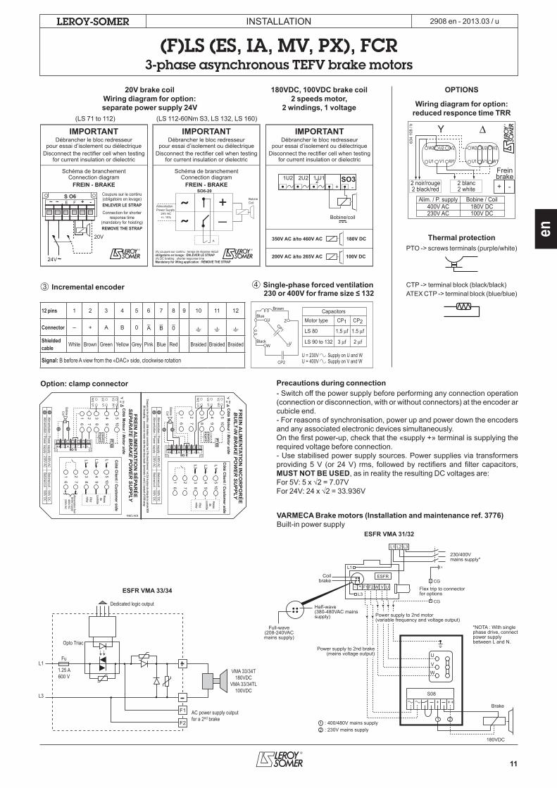
20V brake coilWiring diagram for option:separate power supply 24V
180VDC, 100VDC brake coil2 speeds motor,
2 windings, 1 voltage
OPTIONS
Wiring diagram for option: reduced responce time TRR
Freinbrake
2 noir/rouge2 black/red
Alim. / P. supply400V AC230V AC
Bobine / Coil180V DC100V DC
+ -2 blanc2 white
634
108
/ b
W2 U2 V2
U1 V1 W1
W2 U2 V2
V1 W1U1
Thermal protectionPTO -> screws terminals (purple/white)
CTP -> terminal block (black/black)ATEX CTP -> terminal block (blue/blue)
(LS 71 to 112) (LS 112-60Nm S3, LS 132, LS 160)
IMPORTANTDébrancher le bloc redresseur
pour essai d’isolement ou diélectriqueDisconnect the rectifier cell when testing
for current insulation or dielectric
Schéma de branchementConnection diagram
FREIN - BRAKECoupure sur le continu(obligatoire en levage)ENLEVER LE STRAPConnection for shorter
response time(mandatory for hoisting)REMOVE THE STRAP
24V
20V
E FS O6
~
~
~ -+
IMPORTANTDébrancher le bloc redresseur
pour essai d’isolement ou diélectriqueDisconnect the rectifier cell when testing
for current insulation or dielectric
Schéma de branchementConnection diagram
FREIN - BRAKE
˜˜
+_
SO6-20
AlimentationPower Supply
BobineCoil
24V AC+/- 15%
A
(A) coupure sur continu : temps de réponse réduitobligatoire en levage : ENLEVER LE STRAP(A) DC braking : shorter response timeMandatory for lifting application : REMOVE THE STRAP
IMPORTANTDébrancher le bloc redresseur
pour essai d’isolement ou diélectriqueDisconnect the rectifier cell when testing
for current insulation or dielectric
1U2 2U2 1 U1+ -
2 SO3
Bobine/coil
350V AC à/to 460V AC
200V AC à/to 265V AC
180V DC
100V DC
➂ Incremental encoder
12 pins 1 2 3 4 5 6 7 8 9 10 11 12
Connector – + A B 0_A
_B
_0
Shielded cable White Brown Green Yellow Grey Pink Blue Red Braided Braided Braided
Signal: B before A view from the «DAC» side, clockwise rotation
➃ Single-phase forced ventilation230 or 400V for frame size ≤ 132
Option: clamp connector
VARMECA Brake motors (Installation and maintenance ref. 3776)Built-in power supply
Motor type
Capacitors
CP1 CP2
LS 80 1.5 µf 1.5 µf
LS 90 to 132
U = 230V Supply on U and WU = 400V Supply on V and W
3 µf 2 µf
Brown
Blue
Black
CP2
ZUCP1
W V
Côté C
lient / Custom
er side
Côté M
oteur / Motor side
Côté C
lient / Custom
er sideC
ôté Moteur / M
otor side
Relais de
contrôle
Pilotrelay
L2L3 L1
2 3 4 516 7 8 9 10
CTP/PTCPTO/PTF
216 7
3 4 5
8 9 10
FRE
IN A
LIME
NTA
TION
SÉ
PAR
ÉE
SE
PAR
ATE
BR
AK
E P
OW
ER
SU
PP
LY
L2L3 L1
2 3 4 516 7 8 9 10
CTP/PTCPTO/PTF
216 7
3 4 5
8 9 10
Coupure sur le continu : côté moteur connecter les 2 fils bleus (bornes 1 et 2) à la place du strap de la cellule SO8
DC breaking : connect on motor side the two blue leads (term
inals 1 and 2 ) instead of SO6 strap
634128/b
PT 100
PT 100
Relais de
contrôle
Pilotrelay
W2
U2
V2 ouorU
1
V1
W1
ouor
W2
U2
V2
U1
V1
W1
400V AC230V AC
Alimentation frein
Brake supply
FRE
IN A
LIME
NTA
TION
INC
OR
PO
RÉ
EB
UILT-IN
BR
AK
E P
OW
ER
SU
PP
LY
S O8~~_- +++
S O8~~_- +++
Alimentation / Power supply : 400V AC
Alimentation / Power supply : 230V AC
Bobine/coil : 180V DCBobine/coil : 180V DC
2 1
Alimentation / Power supply : 400V AC
Alimentation / Power supply : 230V AC
Bobine/coil : 180V DCBobine/coil : 180V DC
2 1
2 1
BobineC
oil
BobineC
oil
2 1
Opto Triac
Fu
VMA 33/34T180VDC
VMA 33/34TL100VDC
Dedicated logic output
AC power supply outputfor a 2nd brake
1.25 A600 V
L1
L3
F1
F2
ESFR VMA 33/34
U
V
W
Power supply to 2nd brake(mains voltage output)
: 400/480V mains supply
Brake
180VDC
1: 230V mains supply2
U
ESFRCG
CG
VW+- F2
L1 L2 L3
F1
230/400Vmains supply*
*NOTA : With singlephase drive, connectpower supplybetween L and N.
Coilbrake
Full-wave(208-240VACmains supply)
Power supply to 2nd motor(variable frequency and voltage output)
Half-wave(380-480VAC mainssupply)
Flex trip to connectorfor options
L1
L3
S08
+ ++
1 2
ESFR VMA 31/32
Precautions during connection- Switch off the power supply before performing any connection operation (connection or disconnection, with or without connectors) at the encoder ar cubicle end.- For reasons of synchronisation, power up and power down the encoders and any associated electronic devices simultaneously.On the first power-up, check that the «supply +» terminal is supplying the required voltage before connection.- Use stabilised power supply sources. Power supplies via transformers providing 5 V (or 24 V) rms, followed by rectifiers and filter capacitors, MUST NOT BE USED, as in reality the resulting DC voltages are:For 5V: 5 x √2 = 7.07VFor 24V: 24 x √2 = 33.936V

12
INSTALLATION
(F)LS (ES, IA, MV, PX), FCR3-phase asynchronous TEFV brake motors
2908 en - 2013.03 / uLEROY-SOMER
Alarm and early warningAll protective equipment may be backed up by another type of equipment (with a different NRT). The first device will then act as an «early warning» system (light or sound signals given without shutting down the power circuits), and the second device will be the actual alarm, shutting down the power circuits.
Protection against condensation: space heatersIdentification: 1 red labelA glass fibre flexible resistor is fixed on 1 or 2 coil end turn(s) which heats the machines when stopped and therefore prevents any condensation inside the machines.Power supply: 230 V single phase unless otherwise requested by the customer.The drain plugs underneath the motor should be opened approximately every six months. They should then be replaced to ensure IP -- motor protection.
Thermal magnetic protectionThe motor must be protected by a thermal magnetic device, sited between the isolating switch and the motor. These protective devices safeguard motors fully from non-transient overloads.This device can be fitted with a fused circuit-breaker.
Built-in direct thermal protectionFor low rated currents, bimetallic strip-type protection may be used. The line current passes through the strip, which shuts down or restoresthe supply circuit as necessary. The design of this type of protection allows for manual or automatic reset.
Built-in indirect thermal protectionThe motors can be equipped with optional heat sensors; these sensors can be used to monitor temperature rises at «hot spots»: overload detection, cooling check, monitoring strategic points for installation maintenance.
It must be emphasized that these sensors cannot ever be used todirectly control the motor operating cycles.
Thermal protectionCaution: whatever the type of protection, (PTO or PTF), its NRT must not exceed:
• 150 °C max for the stator and 120 °C max for the shields if the maximum surface temperature = 125 °C.• 160 °C max for the stator and 130°C max for the shields if the maximum surface temperature = 135 °C.• 170 °C max for the stator and 140 °C max for the shields if the maximum surface temperature = 145 °C.
If using sensors with variable resistances or thermocouples, the associated equipment must stop the motor at a temperature of:• 150 °C max for the stator and 120 °C max for the shields if the maximum surface temperature = 125 °C.• 160 °C max for the stator and 130 °C max for the shields if the maximum surface temperature = 135 °C.• 170 °C max for the stator and 140 °C max for the shields if the maximum surface temperature = 145 °C.
Line protection: setting the thermal protective deviceThis must be set at the level of current shown on the motor nameplate for the voltage and frequency of the connected mains supply.
2.6 - Electrical advicesThermal protection and space heaters
Type Operating principle
Operating curve
Breaking capacity (A)
Protectionprovided
Mounting Number required*
Normally closedthermostat
PTO
Bimetallic strip, indirectly heated, with N/C contact 2.5 at 250 V
with cos j 0.4general surveillance fornon-transient overloads
Mounted on control circuit
2 or 3 in series
Normally openthermostat
PTF
Bimetallic strip, indirectly heated, with N/O contact 2.5 at 250 V
with cos j 0.4general surveillance fornon-transient overloads
Mounted on control circuit
2 or 3 in parallel
Positive temperaturecoefficient thermistor
CTP
Variable non-linear resistor,
indirectly heated 0 general surveillance fortransient overloads
Mounted with associated relayon control circuit
3 in series
ThermocouplesT (T < 150 °C)
Constantan copperK (T < 1000 °C)Copper-Nickel
Peltier effect 0continuous surveillanceat hot spots at regular
intervals
Mounted on control panels with associated reading device
(or recording device)
1 per hot spot
Platinum resistancethermometer
PT 100
Variable linearresistor,
indirectly heated0
high accuracy continuoussurveillance at key hot
spots
Mounted on control panels with associated reading device
(or recording device)
1 per hot spot
- NRT: nominal running temperature- The NRTs are chosen according to the position of the sensor in the motor and the class of temperature rise.* The number required affects the protection of the windings.
I
O NRT
T
I
F NRT
T
R
NRT
T
V
T
R
T

13
INSTALLATION
(F)LS (ES, IA, MV, PX), FCR3-phase asynchronous TEFV brake motors
2908 en - 2013.03 / uLEROY-SOMER
en

MOTEURS LEROY-SOMER SAS - RCS 338 567 258 ANGOULÊME - CAPITAL DE 65 800 512 €