Embed Size (px)
Citation preview

Range Specification
Pumps: Pedrollo Range
Max head: 9.7 bar
Number of pumps:
1 - 3
Capacity: 1 x duty pump - up to 12m3/h2 x duty pump - up to 24m3/h3 x duty pump - up to 36m3/h
kW range: ≤ 2.2kW
Power input: 230V/1PH/50Hz
Temperature range: Liquid - Ambient -
up to +40°Cup to +40°C
Pressure rating: PN10
Features- On demand operation- Auto rotation of duty pump- Auto changeover on duty pump trip- Advanced electronic controllers- Flow through controllers- BMS I/O connection- Digitally adjustable cut-in and cut-out pressure- Working pressure range 0.8 - 9 bar - Low friction losses through pump controllers- Anti-vibration mounts for base plate
Protection- Dry run protection- Overload protection- Feed tank low level alarm
Components - Controller per pump- Pressure vessel - Electronic pressure & flow sensors built into controllers- Baseplate & manifolds in 304 Stainless Steel (SS)- Connection box c/w alarm output connection - IP55 enclosure- GSM dial out alarm (Optional)
Control Options
Flow-F - Easy Adjust - Multi Preset
Flow-V - Constant Pressure - Steadypres
• Electronic management of pumps to meet varying demand• Advanced electronic controller per pump• Simple “single entry” setup of operating parameters • Digitally adjustable pressure setting (0.8 - 9 bar) • Thermal overload protection
• Constant working pressure - selectable/adjustable• Variable speed drive (VSD) per pump• Drives are water cooled• Advanced power management• Operation log including; alarms & hours run
A series of small horizontal pumps operating in a cascade system enables high flow demands to be met whilst being efficient during periods of low use.
POWERBOOSTFLOW Range
3
POWERBOOST FLOW Range Controls
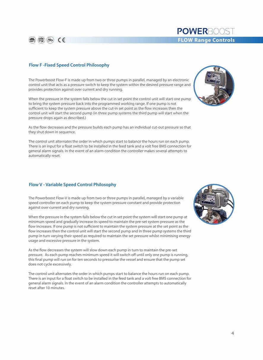
Flow F -Fixed Speed Control Philosophy
Flow V - Variable Speed Control Philosophy
The Powerboost Flow-F is made up from two or three pumps in parallel, managed by an electronic control unit that acts as a pressure switch to keep the system within the desired pressure range and provides protection against over current and dry running.
When the pressure in the system falls below the cut in set point the control unit will start one pump to bring the system pressure back into the programmed working range. If one pump is not sufficient to keep the system pressure above the cut-in set point as the flow increases then the control unit will start the second pump (in three pump systems the third pump will start when the pressure drops again as described.)
As the flow decreases and the pressure builds each pump has an individual cut-out pressure so that they shut down in sequence.
The control unit alternates the order in which pumps start to balance the hours run on each pump.There is an input for a float switch to be installed in the feed tank and a volt free BMS connection for general alarm signals. In the event of an alarm condition the controller makes several attempts to automatically reset.
The Powerboost Flow-V is made up from two or three pumps in parallel, managed by a variable speed controller on each pump to keep the system pressure constant and provide protection against over current and dry running.
When the pressure in the system falls below the cut in set point the system will start one pump at minimum speed and gradually increase its speed to maintain the pre-set system pressure as the flow increases. If one pump is not sufficient to maintain the system pressure at the set point as the flow increases then the control unit will start the second pump and in three pump systems the third pump in turn varying their speed as required to maintain the set pressure whilst minimising energy usage and excessive pressure in the system.
As the flow decreases the system will slow down each pump in turn to maintain the pre-set pressure. As each pump reaches minimum speed it will switch off until only one pump is running, this final pump will run on for ten seconds to pressurise the vessel and ensure that the pump set does not cycle excessively.
The control unit alternates the order in which pumps start to balance the hours run on each pump.There is an input for a float switch to be installed in the feed tank and a volt free BMS connection for general alarm signals. In the event of an alarm condition the controller attempts to automatically reset after 10 minutes.
4

0 10 20 30 40 50 60 70 80 90 100 110 120 130 140 150 160 170 180 190 200
10
20
30
40
500 10 20 30 40
0 1 2 3 4 5 6 7 8 9 10 11 12
Imp g.p.m.
l/min
m³/h
Flow rate Q
Hea
d H
(m
etre
s)
50 Hz n= 2900 rpm HS= 0 m
PLURIJET 3/200
3CR80
3CR100
PLURIJET 3/130
4CR100
0
Flow F - Plurijet Range
Flow F - CR Range
* 230V/1PH/50Hz Power supply for all Flow F booster sets as standard
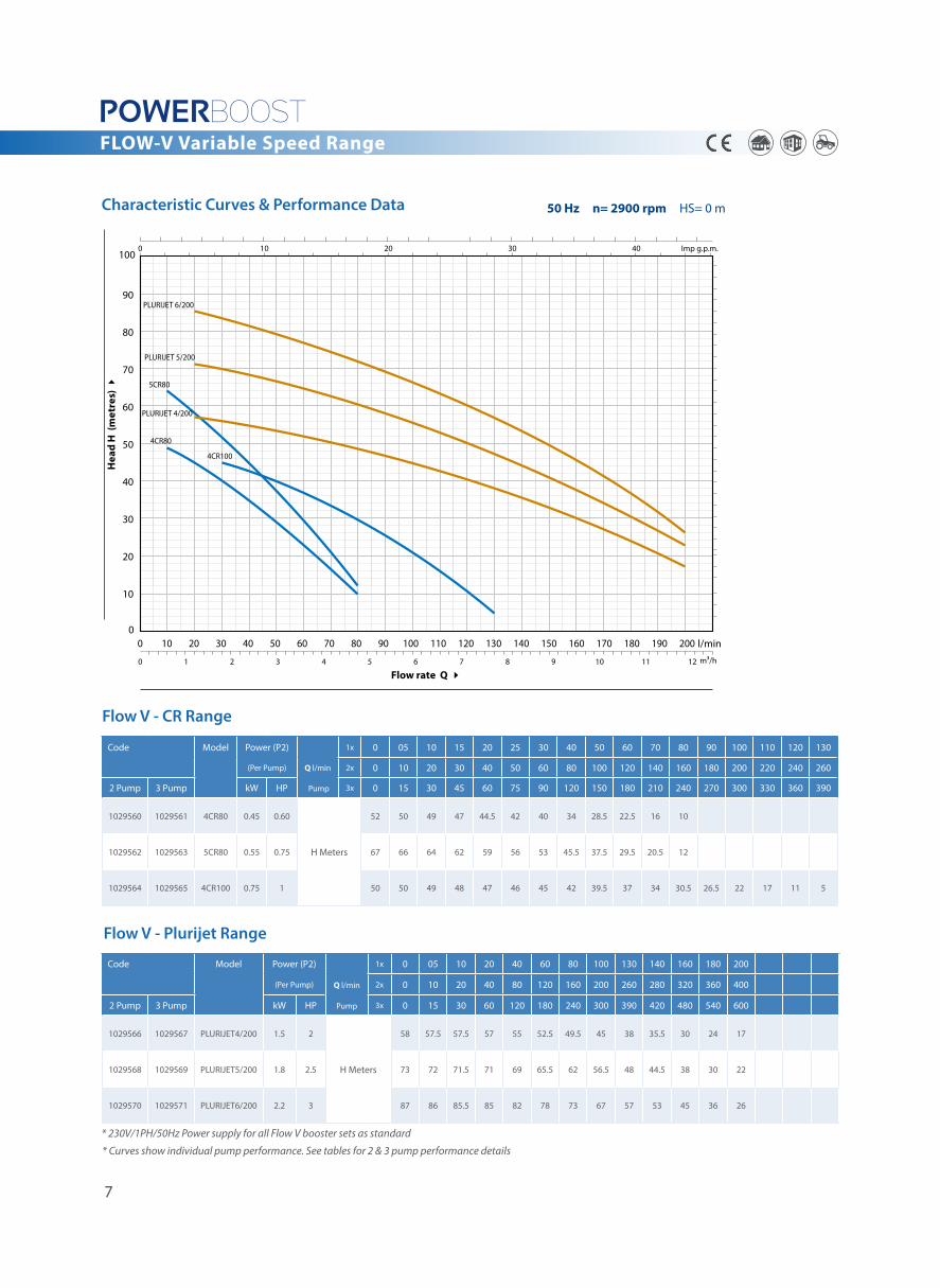
Characteristic Curves & Performance Data
* Curves show individual pump performance. See tables for 2 & 3 pump performance details
Code Model Power (P2) 1x 0 05 10 15 20 25 30 40 50 60 70 80 90 100 110 120 130
(Per Pump) Q l/min 2x 0 10 20 30 40 50 60 80 100 120 140 160 180 200 220 240 260
2 Pump 3 Pump kW HP Pump 3x 0 15 30 45 60 75 90 120 150 180 210 240 270 300 330 360 390
1029550 1029551 3CRm80 0.45 0.60 40 38 37 36 34.5 33 31 27 22.5 17 11 5
1029552 1029553 3CRm100 0.55 0.75 H Meters 38 37 36 35 34.5 33.5 33 31 28 26 23 20 17 13.5 10 5
1029554 1029555 4CRm100 0.75 1 50 50 49 48 47 46 45 42 39.5 37 34 30.5 26.5 22 17 11 5
Code Model Power (P2) 1x 0 05 10 20 40 60 80 100 130 140 160 180 200
(Per Pump) Q l/min 2x 0 10 20 40 80 120 160 200 260 280 320 360 400
2 Pump 3 Pump kW HP Pump 3x 0 15 30 60 120 180 240 300 390 420 480 540 600
1029556 1029557 PLURIJETm3/130 1.1 1.5 49 49 48.5 47.5 45 42.5 38.5 33.5 24
1029558 1029559 PLURIJETm3/200 1.1 1.5 44 43.5 43.5 43 42 40.5 38 35 29 27.5 23 18 13
H Meters
POWERBOOSTFLOW-F Fixed Speed Range
5

Flow-F - Plurijet Range
Model No. Of Pumps FLC(A) H1(mm) H2(mm) H3(mm) L1(mm) L2(mm) W1(mm) W2(mm) PIPE CONNECTIONS
Inlet Outlet
3CRm80 230V2 6.6 200 600 1100 550 440 610 2"BSPP
3 9.9 200 600 1100 850 440 610 2"BSPP
3CRm100 230V2 8.2 200 600 1100 550 440 610 2"BSPP
3 12.3 200 600 1100 850 440 610 2"BSPP
4CRm100 230V2 12 200 600 1100 550 440 610 2"BSPP
3 18 200 600 1100 850 440 610 2"BSPP
Flow-F - CR Range
Model No. Of Pumps FLC(A) H1(mm) H2(mm) H3(mm) L1(mm) L2(mm) W1(mm) W2(mm) PIPE CONNECTIONS
Inlet Outlet
PLURIJETm3/130 230V2 17 220 620 1120 550 440 694 2 1/2"BSPP 2"BSPP
3 22.5 220 620 1120 820 440 694 2 1/2"BSPP 2"BSPP
PLURIJETm3/200 230V2 17 220 620 1120 550 440 694 2 1/2"BSPP 2"BSPP
3 22.5 220 620 1120 820 440 694 2 1/2"BSPP 2"BSPP
* FLC - Full Load Current
POWERBOOST FLOW-F Fixed Speed Range
6
0 10 20 30 40 50 60 70 80 90 100 110 120 130 140 150 160 170 180 190 200
0 10 20 30 40
0 1 2 3 4 5 6 7 8 9 10 11 12
Imp g.p.m.
l/min
m³/h
Flow rate Q
Hea
d H
(m
etre
s)
50 Hz n= 2900 rpm HS= 0 m
4CR80
10
20
30
40
50
60
70
80
90
100
0
5CR80
4CR100
PLURIJET 4/200
PLURIJET 5/200
PLURIJET 6/200
Flow V - Plurijet Range
Flow V - CR Range
* 230V/1PH/50Hz Power supply for all Flow V booster sets as standard
* Curves show individual pump performance. See tables for 2 & 3 pump performance details
Characteristic Curves & Performance Data
POWERBOOSTFLOW-V Variable Speed Range
Code Model Power (P2) 1x 0 05 10 15 20 25 30 40 50 60 70 80 90 100 110 120 130
(Per Pump) Q l/min 2x 0 10 20 30 40 50 60 80 100 120 140 160 180 200 220 240 260
2 Pump 3 Pump kW HP Pump 3x 0 15 30 45 60 75 90 120 150 180 210 240 270 300 330 360 390
1029560 1029561 4CR80 0.45 0.60 52 50 49 47 44.5 42 40 34 28.5 22.5 16 10
1029562 1029563 5CR80 0.55 0.75 H Meters 67 66 64 62 59 56 53 45.5 37.5 29.5 20.5 12
1029564 1029565 4CR100 0.75 1 50 50 49 48 47 46 45 42 39.5 37 34 30.5 26.5 22 17 11 5
Code Model Power (P2) 1x 0 05 10 20 40 60 80 100 130 140 160 180 200
(Per Pump) Q l/min 2x 0 10 20 40 80 120 160 200 260 280 320 360 400
2 Pump 3 Pump kW HP Pump 3x 0 15 30 60 120 180 240 300 390 420 480 540 600
1029566 1029567 PLURIJET4/200 1.5 2 58 57.5 57.5 57 55 52.5 49.5 45 38 35.5 30 24 17
1029568 1029569 PLURIJET5/200 1.8 2.5 H Meters 73 72 71.5 71 69 65.5 62 56.5 48 44.5 38 30 22
1029570 1029571 PLURIJET6/200 2.2 3 87 86 85.5 85 82 78 73 67 57 53 45 36 26
7
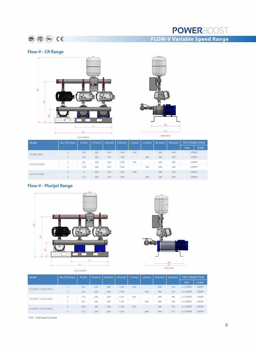
Flow-V - Plurijet Range
POWERBOOST FLOW-V Variable Speed Range
Model No. Of Pumps FLC(A) H1(mm) H2(mm) H3(mm) L1(mm) L2(mm) W1(mm) W2(mm) PIPE CONNECTIONS
Inlet Outlet
4CR80 400V2 6.8 200 610 1100 550 440 590 2"BSPP
3 10.2 200 610 1100 850 440 590 2"BSPP
5CR100 400V2 8.6 200 610 1100 550 440 590 2"BSPP
3 12.9 200 610 1100 850 440 590 2"BSPP
4CR100 400V2 9 200 610 1100 550 440 590 2"BSPP
3 13.5 200 610 1100 850 440 590 2"BSPP
Model No. Of Pumps FLC(A) H1(mm) H2(mm) H3(mm) L1(mm) L2(mm) W1(mm) W2(mm) PIPE CONNECTIONS
Inlet Outlet
PLURIJET 4/200 400V2 16.2 220 630 1130 550 440 720 2 1/2"BSPP 2"BSPP
3 24.3 220 630 1130 850 440 720 2 1/2"BSPP 2"BSPP
PLURIJET 5/200 400V2 17.4 220 630 1130 550 440 746 2 1/2"BSPP 2"BSPP
3 26.1 220 630 1130 850 440 746 2 1/2"BSPP 2"BSPP
PLURIJET 6/200 400V2 20.8 220 630 1130 550 440 772 2 1/2"BSPP 2"BSPP
3 31.2 220 630 1130 850 440 772 2 1/2"BSPP 2"BSPP
* FLC - Full Load Current
Flow-V - CR Range
W2
W2
8