Embed Size (px)
Citation preview

Quick Coupling Products
Catalogue 3800-IND/UK
For your safety!
Under certain circumstances, quick couplings can be subjected to extreme loadings such as vibration and uncontrolled pressure peaks.
Only by using genuine Parker Components and following Parker assembly instructions can you be assured of the reliability and safety of the product and their conformity to the applicable standards.
Failure to follow this rule can adversely affect the functional safety and reliability of products, cause personal injury, property damage, and result in loss of your guarantee rights.
Subject to alteration.
For your safety: see safety guide (pages 58-59).
All dimensions used in this catalogue are in mm otherwise the units are specifi ed. The rated pressure is in MPa.
If necessary you can also use the conversion table on page 60.
The products described herein, including without limitation, products features, dimensions, specifi cations and designs are subject to change by Parker Hannifi n Corporation and its subsidiaries at any time without notice.
For the availability of Parker components, please refer to price list 3893.
© Copyright 2006, Parker Hannifi n Corporation. All Right Reserved.
Catalogue 3800-IND/UK
1 Parker Hannifi n Fluid Connectors Group
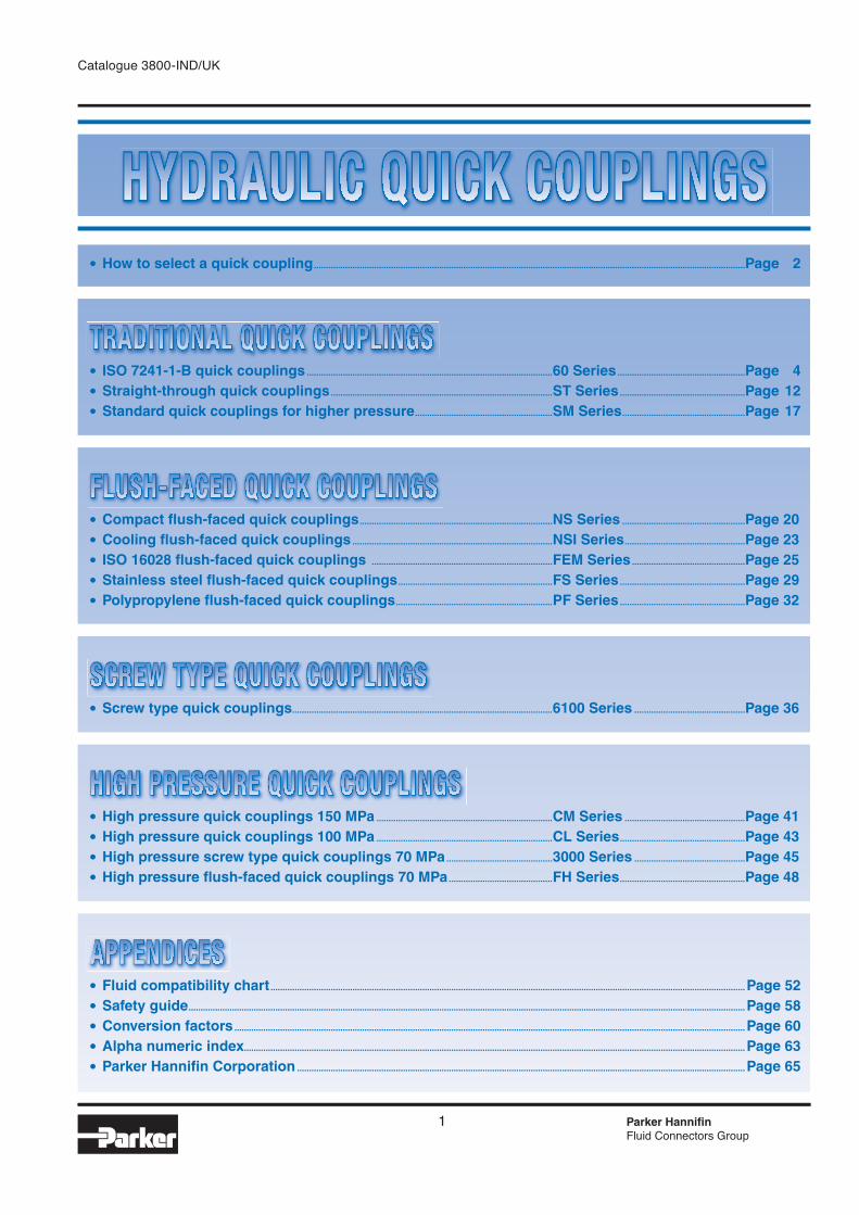
HYDRAULIC QUICK COUPLINGS
● ISO 7241-1-B quick couplings ......................................................................................................60 Series .....................................................Page 4● Straight-through quick couplings ............................................................................................ST Series ....................................................Page 12● Standard quick couplings for higher pressure .........................................................SM Series ...................................................Page 17
TRADITIONAL QUICK COUPLINGS
● How to select a quick coupling ...................................................................................................................................................................................Page 2
● Compact fl ush-faced quick couplings ................................................................................NS Series ...................................................Page 20● Cooling fl ush-faced quick couplings ...................................................................................NSI Series ..................................................Page 23● ISO 16028 fl ush-faced quick couplings ...........................................................................FEM Series ...............................................Page 25● Stainless steel fl ush-faced quick couplings ................................................................FS Series ....................................................Page 29● Polypropylene fl ush-faced quick couplings .................................................................PF Series ....................................................Page 32
FLUSH-FACED QUICK COUPLINGS
● Screw type quick couplings ............................................................................................................6100 Series ..............................................Page 36
SCREW TYPE QUICK COUPLINGS
● High pressure quick couplings 150 MPa .........................................................................CM Series ..................................................Page 41● High pressure quick couplings 100 MPa .........................................................................CL Series ....................................................Page 43● High pressure screw type quick couplings 70 MPa ............................................3000 Series ..............................................Page 45● High pressure fl ush-faced quick couplings 70 MPa ...........................................FH Series ....................................................Page 48
HIGH PRESSURE QUICK COUPLINGS
● Fluid compatibility chart ..................................................................................................................................................................................................... Page 52● Safety guide ....................................................................................................................................................................................................................................... Page 58● Conversion factors .................................................................................................................................................................................................................... Page 60● Alpha numeric index................................................................................................................................................................................................................ Page 63● Parker Hannifi n Corporation .......................................................................................................................................................................................... Page 65
APPENDICES

2 Parker Hannifi n Fluid Connectors Group
Catalogue 3800-IND/UK How to select a hydraulic quick coupling?
*Data shown here are indicative for quick selection purposes only. Please check technical data indicated for each individual series and always refer to safety guide pages 58-59.
max.
Series Traditional quick couplings Flush-faced quick couplings
60 Series ST Series
SM NS NSI FEM
Series Series Series Series
Features Bras
s
Stee
l
Stai
nles
sSt
eel
Bras
s
Stai
nles
sSt
eel
Picture
Standards Interchangeable Interchangeable ISO 7241-1-B with similar with similar ISO 16028 models models
Material Brass Steel Stainless Steel Polypropylene
Size 1/8" 1/4" 3/8" 1/2" 5/8" 3/4" 1" 1 1/4" 1 1/2" 2" 2 1/2" Rated pressure* MPa 1/8" 21.0 35.0 35.0 17.5 29.0 1/4" 25.5 35.0 35.0 36.0 46.0 41.0 6.0 31.5 3/8" 18.5 28.0 35.0 18.5 38.0 17.5 25.0 1/2" 24.0 28.0 35.0 15.0 21.0 41.0 17.5 25.0 5/8" 25.0 3/4" 15.0 17.5 21.0 12.0 21.0 31.0 17.5 25.0 1" 10.5 14.0 21.0 8.0 12.0 17.5 20.0 1 1/4" 12.0 1 1/2" 10.5 10.5 10.5 9.5 2" 2 1/2" 8.5 10.5
Temperature range* -40°C -40°C -40°C -40°C -20°C -20°C (with NBR seal) +110°C +110°C +110°C +110°C +200°C +100°C
Seal NBR or FKM NBR NBR NBR FKM NBR Coupler style Manual Screw-to-connect Push-Pull Push-to-connect
Valving Poppet Flat-faced poppet Ball No Valving
Connection possible with pressure on* Female body Male tip
Locking mechanism Screw type With cam Ball locking mechanism Pawl locking
End confi guration BSPP BSPP BSPT BSPP BSPP BSPP BSPP
NPTF NPTF NPTF NPSF Metric Metric
Full technical data page 4 12 17 20 23 25
and
Catalogue 3800-IND/UK How to select a hydraulic quick coupling?
3 Parker Hannifi n Fluid Connectors Group
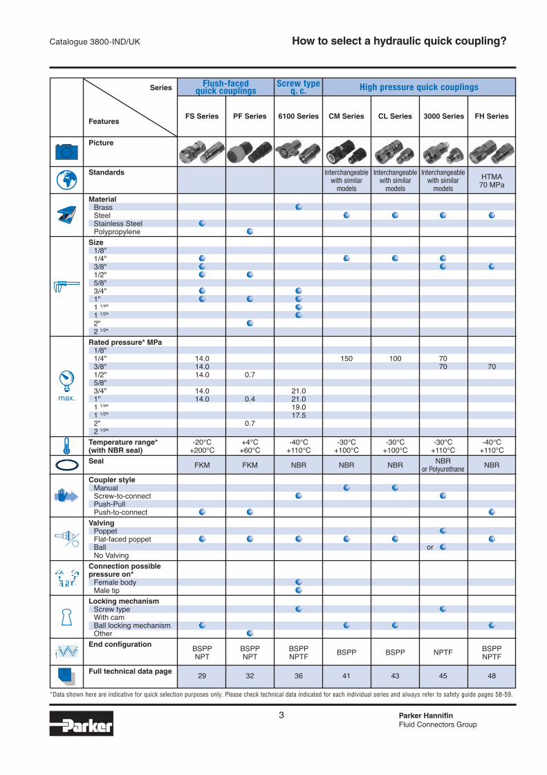
*Data shown here are indicative for quick selection purposes only. Please check technical data indicated for each individual series and always refer to safety guide pages 58-59.
max.
Series Flush-faced Screw type High pressure quick couplings
quick couplings q. c.
FS Series PF Series 6100 Series CM Series CL Series 3000 Series FH Series Features
Picture
Standards Interchangeable Interchangeable Interchangeable with similar with similar with similar HTMA models models models 70 MPa
Material Brass Steel Stainless Steel Polypropylene
Size 1/8" 1/4" 3/8" 1/2" 5/8" 3/4" 1" 1 1/4" 1 1/2" 2" 2 1/2" Rated pressure* MPa 1/8" 1/4" 14.0 150 100 70 3/8" 14.0 70 70 1/2" 14.0 0.7 5/8" 3/4" 14.0 21.0 1" 14.0 0.4 21.0 1 1/4" 19.0 1 1/2" 17.5 2" 0.7 2 1/2"
Temperature range* -20°C +4°C -40°C -30°C -30°C -30°C -40°C (with NBR seal) +200°C +60°C +110°C +100°C +100°C +110°C +110°C
Seal FKM FKM NBR NBR NBR NBR NBR or Polyurethane Coupler style Manual Screw-to-connect Push-Pull Push-to-connect Valving Poppet Flat-faced poppet Ball No Valving Connection possible pressure on* Female body Male tip
Locking mechanism Screw type With cam Ball locking mechanism Other
End confi guration BSPP BSPP BSPP BSPP BSPP NPTF BSPP
NPT NPT NPTF NPTF
Full technical data page 29 32 36 41 43 45 48
or
Catalogue 3800-IND/UK Traditional quick couplings 60 Series
4 Parker Hannifi n Fluid Connectors Group
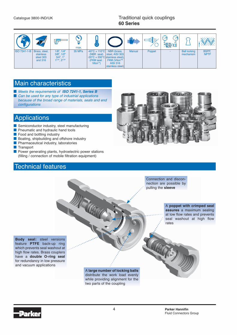
ISO 7241-1-B Brass, steel, 1/8", 1/4" 35 MPa -40°C + 110°C NBR (brass, Manual Poppet - Ball locking BSPP, stainless 3/8", 1/2" (NBR seal) steel, AISI 303 mechanism NPTF steel 303 3/4", 1" -20°C + 200°C stainless steel), and 316 11/2", 21/2" (FKM seal : FKM (VitonTM VitonTM) AISI 316 stainless steel)
Applications■ Semiconductor industry, steel manufacturing■ Pneumatic and hydraulic hand tools■ Food and bottling industry■ Boating, shipbuilding and offshore industry■ Pharmaceutical industry, laboratories■ Transport■ Power generating plants, hydroelectric power stations (fi lling / connection of mobile fi ltration equipment)
Main characteristics■ Meets the requirements of ISO 7241-1, Series B ■ Can be used for any type of industrial applications because of the broad range of materials, seals and end confi gurations
Technical features
Connection and discon-nection are possible by pulling the sleeve
Body seal: steel versions feature PTFE back-up ring which prevents seal washout at high fl ow rates. Brass couplers have a double O-ring seal for redundancy in low pressure and vacuum applications
A poppet with crimped seal assures a maximum sealing at low fl ow rates and prevents seal washout at high fl ow rates
A large number of locking balls distribute the work load evenly while providing alignment for the two parts of the coupling
Catalogue 3800-IND/UK Traditional quick couplings 60 Series
5 Parker Hannifi n Fluid Connectors Group
Technical performance data
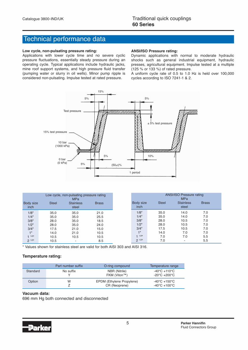
Low cycle, non-pulsating pressure rating:Applications with lower cycle time and no severe cyclic pressure fl uctuations, essentially steady pressure during an operating cycle. Typical applications include hydraulic jacks, mine roof support systems, and high pressure fl uid transfer (pumping water or slurry in oil wells). Minor pump ripple is considered non-pulsating. Impulse tested at rated pressure.
ANSI/ISO Pressure rating:Dynamic applications with normal to moderate hydraulic shocks such as general industrial equipment, hydraulic presses, agricultural equipment. Impulse tested at a multiple (125 % or 133 %) of rated pressure.A uniform cycle rate of 0.5 to 1.0 Hz is held over 100,000 cycles according to ISO 7241-1 & 2.
15%
5%
5%
5% 10%
(50±5)%
10 bar(1000 kPa)
0 bar(0 kPa)
± 5% test pressure
15% test pressure
5%
Vacuum data: 696 mm Hg both connected and disconnected
* Values shown for stainless steel are valid for both AISI 303 and AISI 316.
Temperature rating:
Part number suffi x O-ring compound Temperature range
Standard No suffi x NBR (Nitrile) -40°C +110°C Y FKM (Viton™) -20°C +200°C
Option W EPDM (Ethylene Propylene) -40°C +150°C Z CR (Neoprene) -40°C +100°C
1 period
Test pressure
Low cycle, non-pulsating pressure rating MPa Body size Steel Stainless Brass inch steel
1/8" 35.0 35.0 21.0 1/4" 35.0 35.0 25.5 3/8" 28.0 35.0 18.5 1/2" 28.0 35.0 24.0 3/4" 17.5 21.0 15.0 1" 14.0 21.0 10.5 1 1/2" 10.5 10.5 10.5 2 1/2" 10.5 - 8.5
ANSI/ISO Pressure rating MPa Body size Steel Stainless Brass inch steel
1/8" 35.0 14.0 7.0 1/4" 35.0 14.0 7.0 3/8" 28.0 10.5 7.0 1/2" 28.0 10.5 7.0 3/4" 17.5 10.5 7.0 1" 14.0 7.0 7.0 1 1/2" 7.0 7.0 5.5 2 1/2" 7.0 - 5.5
Catalogue 3800-IND/UK Traditional quick couplings 60 Series
6 Parker Hannifi n Fluid Connectors Group
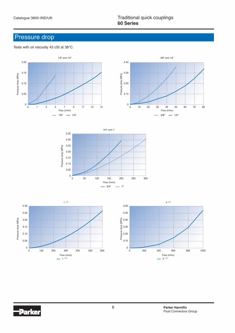
Pressure drop
Tests with oil viscosity 43 cSt at 38°C.
1/8" and 1/4"
Pre
ssur
e dr
op (
MP
a)
Flow (l/min)
3/8" and 1/2"
Pre
ssur
e dr
op (
MP
a)
Flow (l/min)
1 1/2"
Pre
ssur
e dr
op (
MP
a)
Flow (l/min)
2 1/2"
Pre
ssur
e dr
op (
MP
a)
Flow (l/min)
3/4" and 1"
Pre
ssur
e dr
op (
MP
a)
Flow (l/min)
Catalogue 3800-IND/UK Traditional quick couplings 60 Series
7 Parker Hannifi n Fluid Connectors Group
Dimensions and part numbers
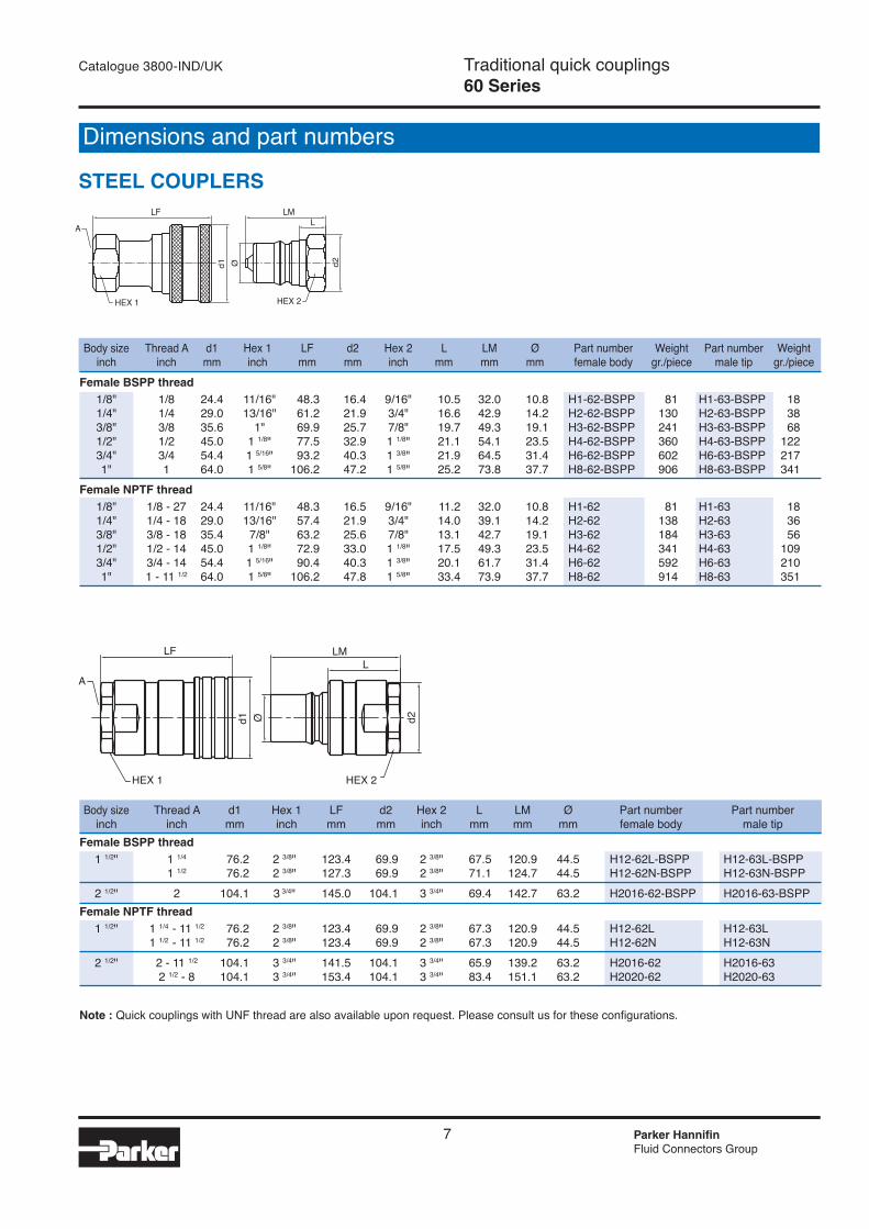
STEEL COUPLERS
Body size Thread A d1 Hex 1 LF d2 Hex 2 L LM Ø Part number Part number inch inch mm inch mm mm inch mm mm mm female body male tip
Female BSPP thread 1 1/2" 1 1/4 76.2 2 3/8" 123.4 69.9 2 3/8" 67.5 120.9 44.5 H12-62L-BSPP H12-63L-BSPP 1 1/2 76.2 2 3/8" 127.3 69.9 2 3/8" 71.1 124.7 44.5 H12-62N-BSPP H12-63N-BSPP
2 1/2" 2 104.1 3 3/4" 145.0 104.1 3 3/4" 69.4 142.7 63.2 H2016-62-BSPP H2016-63-BSPP
Female NPTF thread 1 1/2" 1 1/4 - 11 1/2 76.2 2 3/8" 123.4 69.9 2 3/8" 67.3 120.9 44.5 H12-62L H12-63L 1 1/2 - 11 1/2 76.2 2 3/8" 123.4 69.9 2 3/8" 67.3 120.9 44.5 H12-62N H12-63N
2 1/2" 2 - 11 1/2 104.1 3 3/4" 141.5 104.1 3 3/4" 65.9 139.2 63.2 H2016-62 H2016-63 2 1/2 - 8 104.1 3 3/4" 153.4 104.1 3 3/4" 83.4 151.1 63.2 H2020-62 H2020-63
Note : Quick couplings with UNF thread are also available upon request. Please consult us for these confi gurations.
Body size Thread A d1 Hex 1 LF d2 Hex 2 L LM Ø Part number Weight Part number Weight inch inch mm inch mm mm inch mm mm mm female body gr./piece male tip gr./piece
Female BSPP thread 1/8" 1/8 24.4 11/16" 48.3 16.4 9/16" 10.5 32.0 10.8 H1-62-BSPP 81 H1-63-BSPP 18 1/4" 1/4 29.0 13/16" 61.2 21.9 3/4" 16.6 42.9 14.2 H2-62-BSPP 130 H2-63-BSPP 38 3/8" 3/8 35.6 1" 69.9 25.7 7/8" 19.7 49.3 19.1 H3-62-BSPP 241 H3-63-BSPP 68 1/2" 1/2 45.0 1 1/8" 77.5 32.9 1 1/8" 21.1 54.1 23.5 H4-62-BSPP 360 H4-63-BSPP 122 3/4" 3/4 54.4 1 5/16" 93.2 40.3 1 3/8" 21.9 64.5 31.4 H6-62-BSPP 602 H6-63-BSPP 217 1" 1 64.0 1 5/8" 106.2 47.2 1 5/8" 25.2 73.8 37.7 H8-62-BSPP 906 H8-63-BSPP 341
Female NPTF thread 1/8" 1/8 - 27 24.4 11/16" 48.3 16.5 9/16" 11.2 32.0 10.8 H1-62 81 H1-63 18 1/4" 1/4 - 18 29.0 13/16" 57.4 21.9 3/4" 14.0 39.1 14.2 H2-62 138 H2-63 36 3/8" 3/8 - 18 35.4 7/8" 63.2 25.6 7/8" 13.1 42.7 19.1 H3-62 184 H3-63 56 1/2" 1/2 - 14 45.0 1 1/8" 72.9 33.0 1 1/8" 17.5 49.3 23.5 H4-62 341 H4-63 109 3/4" 3/4 - 14 54.4 1 5/16" 90.4 40.3 1 3/8" 20.1 61.7 31.4 H6-62 592 H6-63 210 1" 1 - 11 1/2 64.0 1 5/8" 106.2 47.8 1 5/8" 33.4 73.9 37.7 H8-62 914 H8-63 351
Catalogue 3800-IND/UK Traditional quick couplings 60 Series
8 Parker Hannifi n Fluid Connectors Group
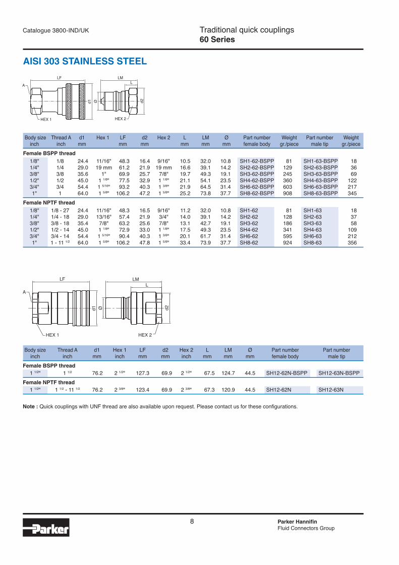
AISI 303 STAINLESS STEEL
Body size Thread A d1 Hex 1 LF d2 Hex 2 L LM Ø Part number Weight Part number Weight inch inch mm mm mm mm mm mm female body gr./piece male tip gr./piece
Female BSPP thread 1/8" 1/8 24.4 11/16" 48.3 16.4 9/16" 10.5 32.0 10.8 SH1-62-BSPP 81 SH1-63-BSPP 18 1/4" 1/4 29.0 19 mm 61.2 21.9 19 mm 16.6 39.1 14.2 SH2-62-BSPP 129 SH2-63-BSPP 36 3/8" 3/8 35.6 1" 69.9 25.7 7/8" 19.7 49.3 19.1 SH3-62-BSPP 245 SH3-63-BSPP 69 1/2" 1/2 45.0 1 1/8" 77.5 32.9 1 1/8" 21.1 54.1 23.5 SH4-62-BSPP 360 SH4-63-BSPP 122 3/4" 3/4 54.4 1 5/16" 93.2 40.3 1 3/8" 21.9 64.5 31.4 SH6-62-BSPP 603 SH6-63-BSPP 217 1" 1 64.0 1 5/8" 106.2 47.2 1 5/8" 25.2 73.8 37.7 SH8-62-BSPP 908 SH8-63-BSPP 345
Female NPTF thread 1/8" 1/8 - 27 24.4 11/16" 48.3 16.5 9/16" 11.2 32.0 10.8 SH1-62 81 SH1-63 18 1/4" 1/4 - 18 29.0 13/16" 57.4 21.9 3/4" 14.0 39.1 14.2 SH2-62 128 SH2-63 37 3/8" 3/8 - 18 35.4 7/8" 63.2 25.6 7/8" 13.1 42.7 19.1 SH3-62 186 SH3-63 58 1/2" 1/2 - 14 45.0 1 1/8" 72.9 33.0 1 1/8" 17.5 49.3 23.5 SH4-62 341 SH4-63 109 3/4" 3/4 - 14 54.4 1 5/16" 90.4 40.3 1 3/8" 20.1 61.7 31.4 SH6-62 595 SH6-63 212 1" 1 - 11 1/2 64.0 1 5/8" 106.2 47.8 1 5/8" 33.4 73.9 37.7 SH8-62 924 SH8-63 356
Body size Thread A d1 Hex 1 LF d2 Hex 2 L LM Ø Part number Part number inch inch mm inch mm mm inch mm mm mm female body male tip
Female BSPP thread 1 1/2" 1 1/2 76.2 2 1/2" 127.3 69.9 2 1/2" 67.5 124.7 44.5 SH12-62N-BSPP SH12-63N-BSPP
Female NPTF thread 1 1/2" 1 1/2 - 11 1/2 76.2 2 3/8" 123.4 69.9 2 3/8" 67.3 120.9 44.5 SH12-62N SH12-63N
Note : Quick couplings with UNF thread are also available upon request. Please contact us for these confi gurations.
Catalogue 3800-IND/UK Traditional quick couplings 60 Series
9 Parker Hannifi n Fluid Connectors Group
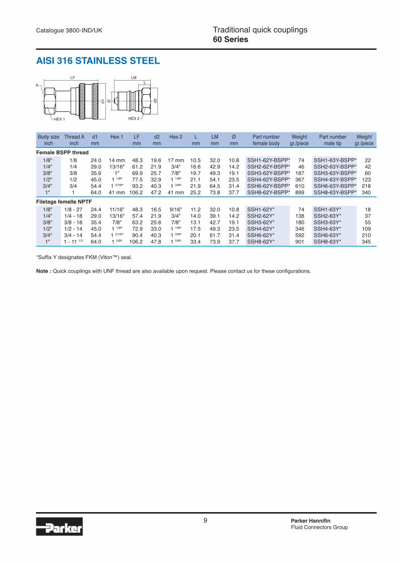
AISI 316 STAINLESS STEEL
Body size Thread A d1 Hex 1 LF d2 Hex 2 L LM Ø Part number Weight Part number Weight inch inch mm mm mm mm mm mm female body gr./piece male tip gr./piece
Female BSPP thread 1/8" 1/8 24.0 14 mm 48.3 19.6 17 mm 10.5 32.0 10.8 SSH1-62Y-BSPP* 74 SSH1-63Y-BSPP* 22 1/4" 1/4 29.0 13/16" 61.2 21.9 3/4" 16.6 42.9 14.2 SSH2-62Y-BSPP* 46 SSH2-63Y-BSPP* 42 3/8" 3/8 35.6 1" 69.9 25.7 7/8" 19.7 49.3 19.1 SSH3-62Y-BSPP* 187 SSH3-63Y-BSPP* 60 1/2" 1/2 45.0 1 1/8" 77.5 32.9 1 1/8" 21.1 54.1 23.5 SSH4-62Y-BSPP* 367 SSH4-63Y-BSPP* 123 3/4" 3/4 54.4 1 5/16" 93.2 40.3 1 3/8" 21.9 64.5 31.4 SSH6-62Y-BSPP* 610 SSH6-63Y-BSPP* 218 1" 1 64.0 41 mm 106.2 47.2 41 mm 25.2 73.8 37.7 SSH8-62Y-BSPP* 899 SSH8-63Y-BSPP* 340
Filetage femelle NPTF 1/8" 1/8 - 27 24.4 11/16" 48.3 16.5 9/16" 11.2 32.0 10.8 SSH1-62Y* 74 SSH1-63Y* 18 1/4" 1/4 - 18 29.0 13/16" 57.4 21.9 3/4" 14.0 39.1 14.2 SSH2-62Y* 138 SSH2-63Y* 37 3/8" 3/8 - 18 35.4 7/8" 63.2 25.6 7/8" 13.1 42.7 19.1 SSH3-62Y* 180 SSH3-63Y* 55 1/2" 1/2 - 14 45.0 1 1/8" 72.9 33.0 1 1/8" 17.5 49.3 23.5 SSH4-62Y* 346 SSH4-63Y* 109 3/4" 3/4 - 14 54.4 1 5/16" 90.4 40.3 1 3/8" 20.1 61.7 31.4 SSH6-62Y* 592 SSH6-63Y* 210 1" 1 - 11 1/2 64.0 1 5/8" 106.2 47.8 1 5/8" 33.4 73.9 37.7 SSH8-62Y* 901 SSH8-63Y* 345
*Suffi x Y designates FKM (Viton™) seal.
Note : Quick couplings with UNF thread are also available upon request. Please contact us for these confi gurations.
Catalogue 3800-IND/UK Traditional quick couplings 60 Series
10 Parker Hannifi n Fluid Connectors Group
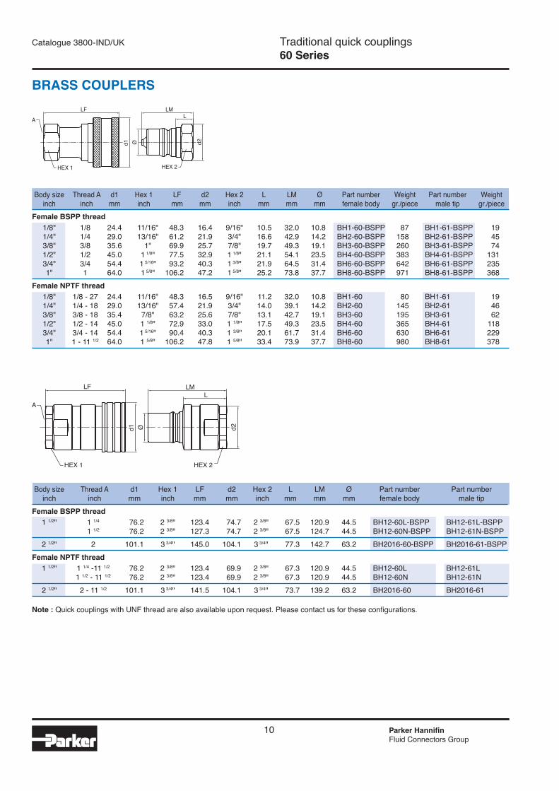
BRASS COUPLERS
Body size Thread A d1 Hex 1 LF d2 Hex 2 L LM Ø Part number Weight Part number Weight inch inch mm inch mm mm inch mm mm mm female body gr./piece male tip gr./piece
Female BSPP thread 1/8" 1/8 24.4 11/16" 48.3 16.4 9/16" 10.5 32.0 10.8 BH1-60-BSPP 87 BH1-61-BSPP 19 1/4" 1/4 29.0 13/16" 61.2 21.9 3/4" 16.6 42.9 14.2 BH2-60-BSPP 158 BH2-61-BSPP 45 3/8" 3/8 35.6 1" 69.9 25.7 7/8" 19.7 49.3 19.1 BH3-60-BSPP 260 BH3-61-BSPP 74 1/2" 1/2 45.0 1 1/8" 77.5 32.9 1 1/8" 21.1 54.1 23.5 BH4-60-BSPP 383 BH4-61-BSPP 131 3/4" 3/4 54.4 1 5/16" 93.2 40.3 1 3/8" 21.9 64.5 31.4 BH6-60-BSPP 642 BH6-61-BSPP 235 1" 1 64.0 1 5/8" 106.2 47.2 1 5/8" 25.2 73.8 37.7 BH8-60-BSPP 971 BH8-61-BSPP 368
Female NPTF thread 1/8" 1/8 - 27 24.4 11/16" 48.3 16.5 9/16" 11.2 32.0 10.8 BH1-60 80 BH1-61 19 1/4" 1/4 - 18 29.0 13/16" 57.4 21.9 3/4" 14.0 39.1 14.2 BH2-60 145 BH2-61 46 3/8" 3/8 - 18 35.4 7/8" 63.2 25.6 7/8" 13.1 42.7 19.1 BH3-60 195 BH3-61 62 1/2" 1/2 - 14 45.0 1 1/8" 72.9 33.0 1 1/8" 17.5 49.3 23.5 BH4-60 365 BH4-61 118 3/4" 3/4 - 14 54.4 1 5/16" 90.4 40.3 1 3/8" 20.1 61.7 31.4 BH6-60 630 BH6-61 229 1" 1 - 11 1/2 64.0 1 5/8" 106.2 47.8 1 5/8" 33.4 73.9 37.7 BH8-60 980 BH8-61 378
Body size Thread A d1 Hex 1 LF d2 Hex 2 L LM Ø Part number Part number inch inch mm inch mm mm inch mm mm mm female body male tip
Female BSPP thread 1 1/2" 1 1/4 76.2 2 3/8" 123.4 74.7 2 3/8" 67.5 120.9 44.5 BH12-60L-BSPP BH12-61L-BSPP 1 1/2 76.2 2 3/8" 127.3 74.7 2 3/8" 67.5 124.7 44.5 BH12-60N-BSPP BH12-61N-BSPP
2 1/2" 2 101.1 3 3/4" 145.0 104.1 3 3/4" 77.3 142.7 63.2 BH2016-60-BSPP BH2016-61-BSPP
Female NPTF thread 1 1/2" 1 1/4 -11 1/2 76.2 2 3/8" 123.4 69.9 2 3/8" 67.3 120.9 44.5 BH12-60L BH12-61L 1 1/2 - 11 1/2 76.2 2 3/8" 123.4 69.9 2 3/8" 67.3 120.9 44.5 BH12-60N BH12-61N
2 1/2" 2 - 11 1/2 101.1 3 3/4" 141.5 104.1 3 3/4" 73.7 139.2 63.2 BH2016-60 BH2016-61
Note : Quick couplings with UNF thread are also available upon request. Please contact us for these confi gurations.
Catalogue 3800-IND/UK Traditional quick couplings 60 Series
11 Parker Hannifi n Fluid Connectors Group
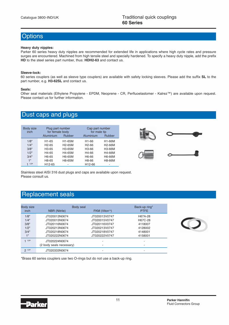
Dust caps and plugs
Replacement seals
Options
Body size Plug part number Cap part number inch for female body for male tip Aluminium Rubber Aluminium Rubber
1/8" H1-65 H1-65M H1-66 H1-66M 1/4" H2-65 H2-65M H2-66 H2-66M 3/8" H3-65 H3-65M H3-66 H3-66M 1/2" H4-65 H4-65M H4-66 H4-66M 3/4" H6-65 H6-65M H6-66 H6-66M 1" H8-65 H8-65M H8-66 H8-66M 1 1/2" H12-65 - H12-66 -
Heavy duty nipples:Parker 60 series heavy duty nipples are recommended for extended life in applications where high cycle rates and pressure surges are encountered. Machined from high tensile steel and specially hardened. To specify a heavy duty nipple, add the prefi x HD to the steel series part number, thus: HDH2-63 and contact us.
Sleeve-lock:60 series couplers (as well as sleeve type couplers) are available with safety locking sleeves. Please add the suffi x SL to the part number, e.g. H3-62SL and contact us.
Seals:Other seal materials (Ethylene Propylene - EPDM, Neoprene - CR, Perfl uoelastomer - Kalrez™) are available upon request. Please contact us for further information.
Stainless steel AISI 316 dust plugs and caps are available upon request.Please consult us.
Body size Body seal Back-up ring* inch NBR (Nitrile) FKM (VitonTM) PTFE
1/8" JT020013N0674 JT020013V0747 H67A-28 1/4" JT020015N0674 JT020015V0747 H67C-28 3/8" JT020116N0674 JT020116V0747 4118007 1/2" JT020213N0674 JT020213V0747 4128002 3/4" JT020218N0674 JT020218V0747 4148001 1" JT020222N0674 JT020222V0747 4158001
1 1/2" JT020224N0674 - - (2 body seals necessary) - -
2 1/2" JT020333N0674 - -
*Brass 60 series couplers use two O-rings but do not use a back-up ring.
Catalogue 3800-IND/UK Traditional quick couplings ST Series
12 Parker Hannifi n Fluid Connectors Group
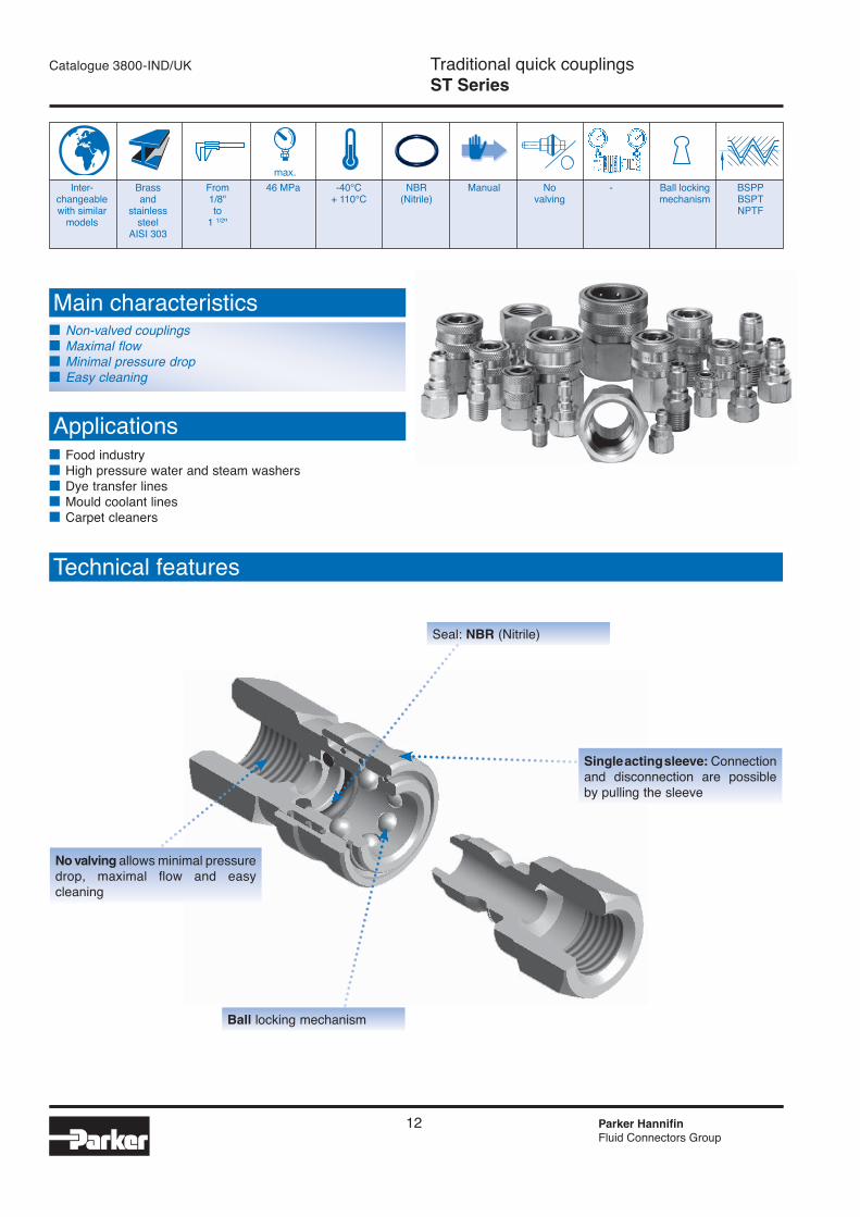
Main characteristics
Applications■ Food industry■ High pressure water and steam washers■ Dye transfer lines■ Mould coolant lines■ Carpet cleaners
Technical features
■ Non-valved couplings■ Maximal fl ow■ Minimal pressure drop■ Easy cleaning
Inter- Brass From 46 MPa -40°C NBR Manual No - Ball locking BSPP changeable and 1/8" + 110°C (Nitrile) valving mechanism BSPT with similar stainless to NPTF models steel 1 1/2" AISI 303
No valving allows minimal pressure drop, maximal fl ow and easy cleaning
Ball locking mechanism
Seal: NBR (Nitrile)
Single acting sleeve: Connection and disconnection are possible by pulling the sleeve
Catalogue 3800-IND/UK Traditional quick couplings ST Series
13 Parker Hannifi n Fluid Connectors Group
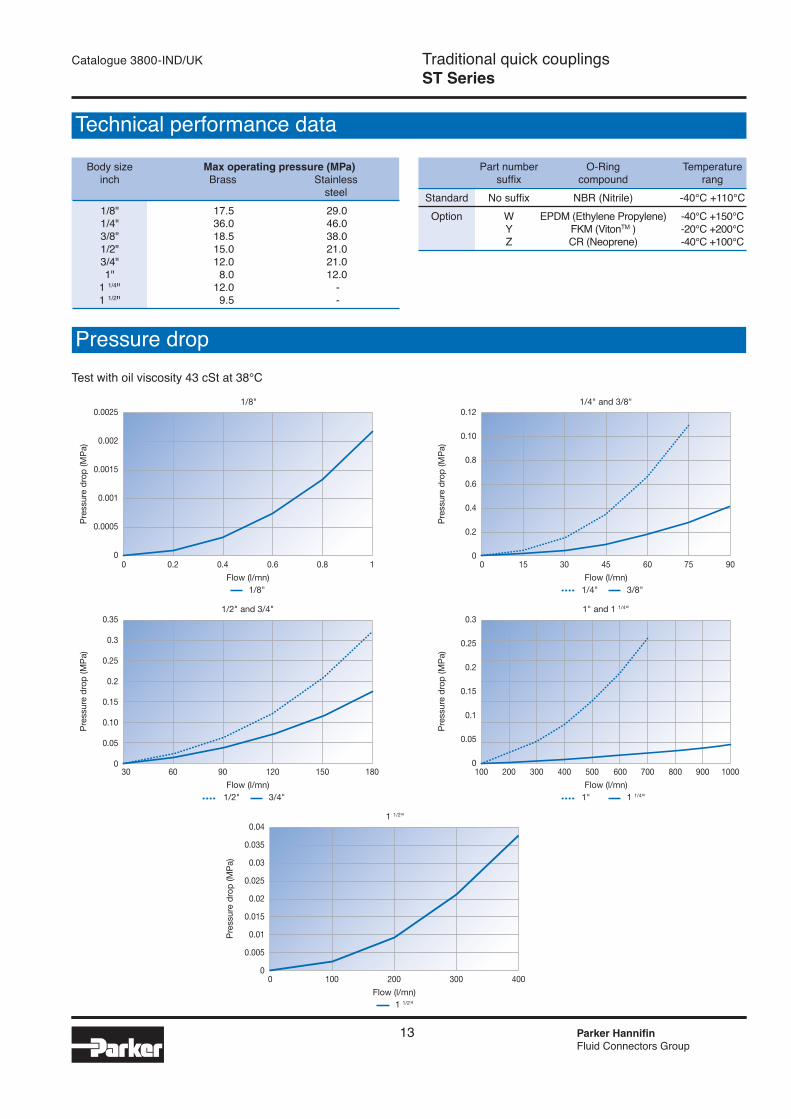
Technical performance data
Pressure drop
Test with oil viscosity 43 cSt at 38°C
Body size Max operating pressure (MPa) inch Brass Stainless steel
1/8" 17.5 29.0 1/4" 36.0 46.0 3/8" 18.5 38.0 1/2" 15.0 21.0 3/4" 12.0 21.0 1" 8.0 12.0 1 1/4" 12.0 - 1 1/2" 9.5 -
Part number O-Ring Temperature suffi x compound rang
Standard No suffi x NBR (Nitrile) -40°C +110°C
Option W EPDM (Ethylene Propylene) -40°C +150°C Y FKM (VitonTM ) -20°C +200°C Z CR (Neoprene) -40°C +100°C
30 60 90 120 150 180
Flow (l/mn)
0.35
0.3
0.25
0.2
0.15
0.10
0.05
0
Pre
ssur
e d
rop
(MP
a)
100 200 300 400 500 600 700 800 900 1000
Flow (l/mn)
0.3
0.25
0.2
0.15
0.1
0.05
0
Pre
ssur
e d
rop
(MP
a)
1/2" 3/4" 1" 1 1/4"
0 0.2 0.4 0.6 0.8 1
Flow (l/mn)
0.0025
0.002
0.0015
0.001
0.0005
0
Pre
ssur
e d
rop
(MP
a)
0 15 30 45 60 75 90
Flow (l/mn)
0.12
0.10
0.8
0.6
0.4
0.2
0
Pre
ssur
e d
rop
(MP
a)
1/8" 1/4" 3/8"
0 100 200 300 400
Flow (l/mn)
0.04
0.035
0.03
0.025
0.02
0.015
0.01
0.005
0
Pre
ssur
e d
rop
(MP
a)
1 1/2"
1/2" and 3/4" 1" and 1 1/4"
1/8" 1/4" and 3/8"
1 1/2"
Catalogue 3800-IND/UK Traditional quick couplings ST Series
14 Parker Hannifi n Fluid Connectors Group
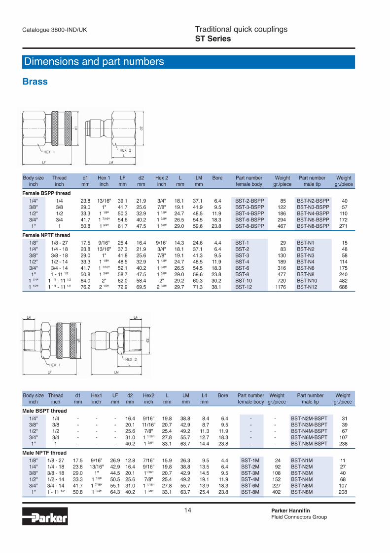
Dimensions and part numbers
Brass
Body size Thread d1 Hex1 LF d2 Hex2 L LM L4 Bore Part number Weight Part number Weight inch inch mm inch mm mm inch mm mm mm female body gr./piece male tip gr./piece
Male BSPT thread 1/4" 1/4 - - - 16.4 9/16" 19.8 38.8 8.4 6.4 - - BST-N2M-BSPT 31 3/8" 3/8 - - - 20.1 11/16" 20.7 42.9 8.7 9.5 - - BST-N3M-BSPT 39 1/2" 1/2 - - - 25.6 7/8" 25.4 49.2 11.3 11.9 - - BST-N4M-BSPT 67 3/4" 3/4 - - - 31.0 1 1/16" 27.8 55.7 12.7 18.3 - - BST-N6M-BSPT 107 1" 1 - - - 40.2 1 3/8" 33.1 63.7 14.4 23.8 - - BST-N8M-BSPT 238
Male NPTF thread 1/8" 1/8 - 27 17.5 9/16" 26.9 12.8 7/16" 15.9 26.3 9.5 4.4 BST-1M 24 BST-N1M 11 1/4" 1/4 - 18 23.8 13/16" 42.9 16.4 9/16" 19.8 38.8 13.5 6.4 BST-2M 92 BST-N2M 27 3/8" 3/8 - 18 29.0 1" 44.5 20.1 11/16" 20.7 42.9 14.5 9.5 BST-3M 108 BST-N3M 40 1/2" 1/2 - 14 33.3 1 1/8" 50.5 25.6 7/8" 25.4 49.2 19.1 11.9 BST-4M 152 BST-N4M 68 3/4" 3/4 - 14 41.7 1 7/16" 55.1 31.0 1 1/16" 27.8 55.7 13.9 18.3 BST-6M 227 BST-N6M 107 1" 1 - 11 1/2 50.8 1 3/4" 64.3 40.2 1 3/8" 33.1 63.7 25.4 23.8 BST-8M 402 BST-N8M 208
Body size Thread d1 Hex 1 LF d2 Hex 2 L LM Bore Part number Weight Part number Weight inch inch mm inch mm mm inch mm mm female body gr./piece male tip gr./piece
Female BSPP thread 1/4" 1/4 23.8 13/16" 39.1 21.9 3/4" 18.1 37.1 6.4 BST-2-BSPP 85 BST-N2-BSPP 40 3/8" 3/8 29.0 1" 41.7 25.6 7/8" 19.1 41.9 9.5 BST-3-BSPP 122 BST-N3-BSPP 57 1/2" 1/2 33.3 1 1/8" 50.3 32.9 1 1/8" 24.7 48.5 11.9 BST-4-BSPP 186 BST-N4-BSPP 110 3/4" 3/4 41.7 1 7/16" 54.6 40.2 1 3/8" 26.5 54.5 18.3 BST-6-BSPP 294 BST-N6-BSPP 172 1" 1 50.8 1 3/4" 61.7 47.5 1 5/8" 29.0 59.6 23.8 BST-8-BSPP 467 BST-N8-BSPP 271
Female NPTF thread 1/8" 1/8 - 27 17.5 9/16" 25.4 16.4 9/16" 14.3 24.6 4.4 BST-1 29 BST-N1 15 1/4" 1/4 - 18 23.8 13/16" 37.3 21.9 3/4" 18.1 37.1 6.4 BST-2 83 BST-N2 48 3/8" 3/8 - 18 29.0 1" 41.8 25.6 7/8" 19.1 41.3 9.5 BST-3 130 BST-N3 58 1/2" 1/2 - 14 33.3 1 1/8" 48.5 32.9 1 1/8" 24.7 48.5 11.9 BST-4 189 BST-N4 114 3/4" 3/4 - 14 41.7 1 7/16" 52.1 40.2 1 3/8" 26.5 54.5 18.3 BST-6 316 BST-N6 175 1" 1 - 11 1/2 50.8 1 3/4" 58.7 47.5 1 5/8" 29.0 59.6 23.8 BST-8 477 BST-N8 240 1 1/4" 1 1/4 - 11 1/2 64.0 2" 62.0 58.4 2" 29.2 60.3 30.2 BST-10 720 BST-N10 482 1 1/2" 1 1/4 - 11 1/2 76.2 2 1/2" 72.9 69.5 2 3/8" 29.7 71.3 38.1 BST-12 1176 BST-N12 688
Catalogue 3800-IND/UK Traditional quick couplings ST Series
15 Parker Hannifi n Fluid Connectors Group
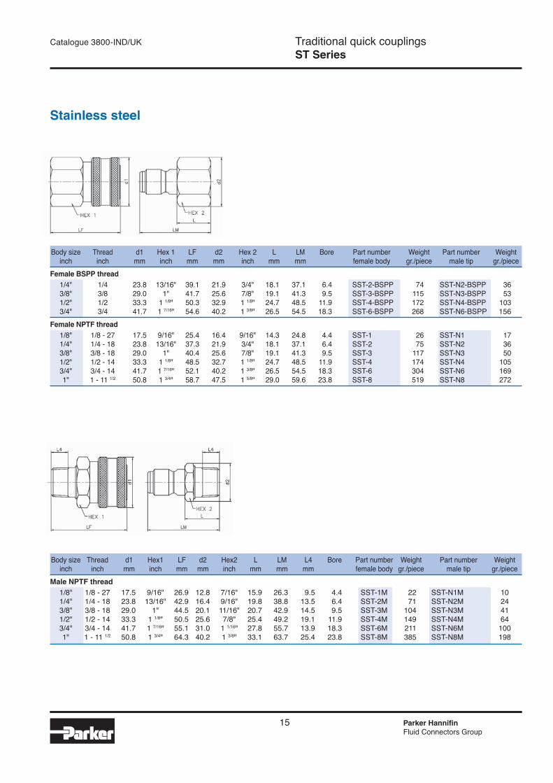
Stainless steel
Body size Thread d1 Hex1 LF d2 Hex2 L LM L4 Bore Part number Weight Part number Weight inch inch mm inch mm mm inch mm mm mm female body gr./piece male tip gr./piece
Male NPTF thread 1/8" 1/8 - 27 17.5 9/16" 26.9 12.8 7/16" 15.9 26.3 9.5 4.4 SST-1M 22 SST-N1M 10 1/4" 1/4 - 18 23.8 13/16" 42.9 16.4 9/16" 19.8 38.8 13.5 6.4 SST-2M 71 SST-N2M 24 3/8" 3/8 - 18 29.0 1" 44.5 20.1 11/16" 20.7 42.9 14.5 9.5 SST-3M 104 SST-N3M 41 1/2" 1/2 - 14 33.3 1 1/8" 50.5 25.6 7/8" 25.4 49.2 19.1 11.9 SST-4M 149 SST-N4M 64 3/4" 3/4 - 14 41.7 1 7/16" 55.1 31.0 1 1/16" 27.8 55.7 13.9 18.3 SST-6M 211 SST-N6M 100 1" 1 - 11 1/2 50.8 1 3/4" 64.3 40.2 1 3/8" 33.1 63.7 25.4 23.8 SST-8M 385 SST-N8M 198
Body size Thread d1 Hex 1 LF d2 Hex 2 L LM Bore Part number Weight Part number Weight inch inch mm inch mm mm inch mm mm female body gr./piece male tip gr./piece
Female BSPP thread 1/4" 1/4 23.8 13/16" 39.1 21.9 3/4" 18.1 37.1 6.4 SST-2-BSPP 74 SST-N2-BSPP 36 3/8" 3/8 29.0 1" 41.7 25.6 7/8" 19.1 41.3 9.5 SST-3-BSPP 115 SST-N3-BSPP 53 1/2" 1/2 33.3 1 1/8" 50.3 32.9 1 1/8" 24.7 48.5 11.9 SST-4-BSPP 172 SST-N4-BSPP 103 3/4" 3/4 41.7 1 7/16" 54.6 40.2 1 3/8" 26.5 54.5 18.3 SST-6-BSPP 268 SST-N6-BSPP 156
Female NPTF thread 1/8" 1/8 - 27 17.5 9/16" 25.4 16.4 9/16" 14.3 24.8 4.4 SST-1 26 SST-N1 17 1/4" 1/4 - 18 23.8 13/16" 37.3 21.9 3/4" 18.1 37.1 6.4 SST-2 75 SST-N2 36 3/8" 3/8 - 18 29.0 1" 40.4 25.6 7/8" 19.1 41.3 9.5 SST-3 117 SST-N3 50 1/2" 1/2 - 14 33.3 1 1/8" 48.5 32.7 1 1/8" 24.7 48.5 11.9 SST-4 174 SST-N4 105 3/4" 3/4 - 14 41.7 1 7/16" 52.1 40.2 1 3/8" 26.5 54.5 18.3 SST-6 304 SST-N6 169 1" 1 - 11 1/2 50.8 1 3/4" 58.7 47.5 1 5/8" 29.0 59.6 23.8 SST-8 519 SST-N8 272
Catalogue 3800-IND/UK Traditional quick couplings ST Series
16 Parker Hannifi n Fluid Connectors Group
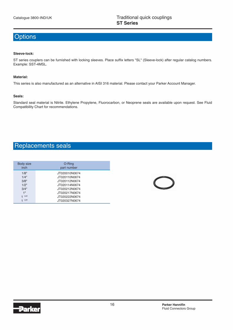
Options
Sleeve-lock:
ST series couplers can be furnished with locking sleeves. Place suffi x letters "SL" (Sleeve-lock) after regular catalog numbers. Example: SST-4MSL.
Material:
This series is also manufactured as an alternative in AISI 316 material. Please contact your Parker Account Manager.
Seals:
Standard seal material is Nitrile. Ethylene Propylene, Fluorocarbon, or Neoprene seals are available upon request. See Fluid Compatibility Chart for recommendations.
Replacements seals
Body size O-Ring inch part number
1/8" JT020010N0674 1/4" JT020110N0674 3/8" JT020112N0674 1/2" JT020114N0674 3/4" JT020212N0674 1" JT020217N0674 1 1/4" JT020222N0674 1 1/2" JT020327N0674
Catalogue 3800-IND/UK Traditional quick couplings SM Series
17 Parker Hannifi n Fluid Connectors Group
Main characteristics
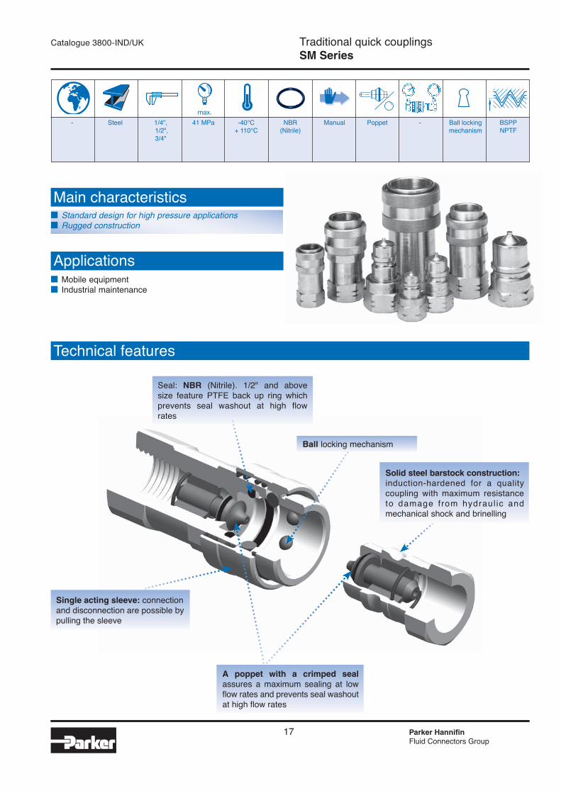
Applications■ Mobile equipment■ Industrial maintenance
Technical features
■ Standard design for high pressure applications■ Rugged construction
- Steel 1/4", 41 MPa -40°C NBR Manual Poppet - Ball locking BSPP 1/2", + 110°C (Nitrile) mechanism NPTF 3/4"
Single acting sleeve: connection and disconnection are possible by pulling the sleeve
A poppet with a crimped seal assures a maximum sealing at low fl ow rates and prevents seal washout at high fl ow rates
Seal: NBR (Nitrile). 1/2" and above size feature PTFE back up ring which prevents seal washout at high fl ow rates
Solid steel barstock construction: induction-hardened for a quality coupling with maximum resistance to damage from hydraul ic and mechanical shock and brinelling
Ball locking mechanism
Catalogue 3800-IND/UK Traditional quick couplings SM Series
18 Parker Hannifi n Fluid Connectors Group
Technical performance data
Pressure drop
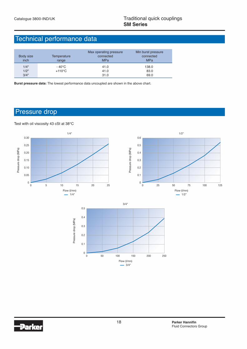
Test with oil viscosity 43 cSt at 38°C
Max operating pressure Min burst pressure Body size Temperature connected connected inch range MPa MPa
1/4" - 40°C 41.0 138.0 1/2" +110°C 41.0 83.0 3/4" 31.0 69.0
Burst pressure data: The lowest performance data uncoupled are shown in the above chart.
0 50 100 150 200 250
Flow (l/mn)
0.5
0.4
0.3
0.2
0.1
0
Pre
ssur
e d
rop
(MP
a)
3/4"
3/4"
0 5 10 15 20 25
Flow (l/mn)
0.30
0.25
0.20
0.15
0.10
0.05
0
Pre
ssur
e d
rop
(MP
a)
0 25 50 75 100 125
Flow (l/mn)
0.6
0.5
0.4
0.3
0.2
0.1
0
Pre
ssur
e d
rop
(MP
a)1/4" 1/2"
1/4" 1/2"

Catalogue 3800-IND/UK Traditional quick couplings SM Series
19 Parker Hannifi n Fluid Connectors Group
Dimensions and part numbers
Body size Thread d1 Hex 1 LF d2 Hex 2 E* LM Part number Weight Part number Weight inch inch mm inch mm mm inch mm mm female body gr./piece male tip gr./piece
Female BSPP thread 1/4" 1/4 26.9 3/4" 56.9 22.1 3/4" 21.6 41.7 SM-251-4FB 128 SM-252-4FB 43 1/4" 3/8 26.9 15/16" 56.9 27.4 15/16" 25.7 41.7 SM-251-6FB 131 SM-252-6FB 63 1/2" 1/2 39.6 1 1/4" 76.2 31.2 1 1/16" 16.5 51.1 SM-501-8FB 329 SM-502-8FB 76 1/2" 3/4 39.6 1 3/8" 80.3 40.4 1 3/8" 27.9 66.8 SM-501-12FB 380 SM-502-12FB 156 3/4" 3/4 56.4 1 5/8" 98.8 43.9 1 1/2" 18.5 66.0 SM-751-12FB 853 SM-752-12FB 247 3/4" 1 56.4 1 5/8" 101.1 47.8 1 5/8" 22.1 68.3 SM-751-16FB 825 SM-752-16FB 239
Female NPTF thread 1/4" 1/4 - 18 26.9 3/4" 53.1 22.1 3/4" 17.8 37.8 SM-251-4FP 110 SM-252-4FP 33 1/4" 3/8 - 18 26.9 15/16" 56.9 27.4 15/16" 25.7 41.7 SM-251-6FP 123 SM-252-6FP 67 1/2" 1/2 - 14 39.6 1 1/4" 76.2 31.2 1 1/16" 23.4 51.1 SM-501-8FP 319 SM-502-8FP 70 1/2" 3/4 - 14 39.6 1 3/8" 78.0 40.4 1 3/8" 20.3 58.7 SM-501-12FP 381 SM-502-12FP 151 3/4" 3/4 - 14 56.4 1 5/8" 95.8 43.9 1 1/2" 15.0 63.0 SM-751-12FP 822 SM-752-12FP 231 3/4" 1 - 11 1/2 56.4 1 5/8" 101.1 47.8 1 5/8" 22.1 68.3 SM-751-16FP 838 SM-752-16FP 278
E* = exposed length. This dimension represents the portion that is exposed when the nipple is inserted into the mating Parker coupler.
Dust caps and plugs Body size Plug part number Cap part number inch for female body for male tip
Rubber 1/4" PR-25 CR-25 1/2" DP-50 DC-50
Aluminium 1/4" P-25 C-25 1/2" P-50 C-50 3/4" P-75 C-75
Replacements seals Body size Plug part number Cap part number inch for female body for male tip
1/4" JT020113N0674 - 1/2" JT020211N0674 50014-211 3/4" JT020219N0674 50014-219
Catalogue 3800-IND/UK Flush-faced quick couplings NS Series
20 Parker Hannifi n Fluid Connectors Group
Main characteristics
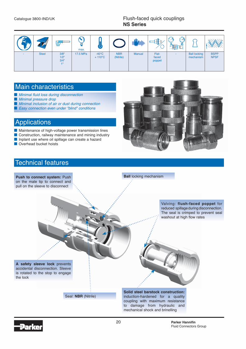
Applications■ Maintenance of high-voltage power transmission lines■ Construction, railway maintenance and mining industry■ Inplant use where oil spillage can create a hazard■ Overhead bucket hoists
Technical features
A safety sleeve lock prevents accidental disconnection. Sleeve is rotated to the stop to engage the lock
Seal: NBR (Nitrile)
Ball locking mechanism
Valving: flush-faced poppet for reduced spillage during disconnection. The seal is crimped to prevent seal washout at high fl ow rates
Push to connect system: Push on the male tip to connect and pull on the sleeve to disconnect
Solid steel barstock construction: induction-hardened for a quality coupling with maximum resistance to damage from hydraulic and mechanical shock and brinelling
■ Minimal fl uid loss during disconnection■ Minimal pressure drop■ Minimal inclusion of air or dust during connection■ Easy connection even under "blind" conditions
- Steel 3/8" 17.5 MPa -40°C NBR Manual Flat- - Ball locking BSPP 1/2" + 110°C (Nitrile) faced mechanism NPSF 3/4" poppet 1"
Catalogue 3800-IND/UK Flush-faced quick couplings NS Series
21 Parker Hannifi n Fluid Connectors Group
Technical performance data
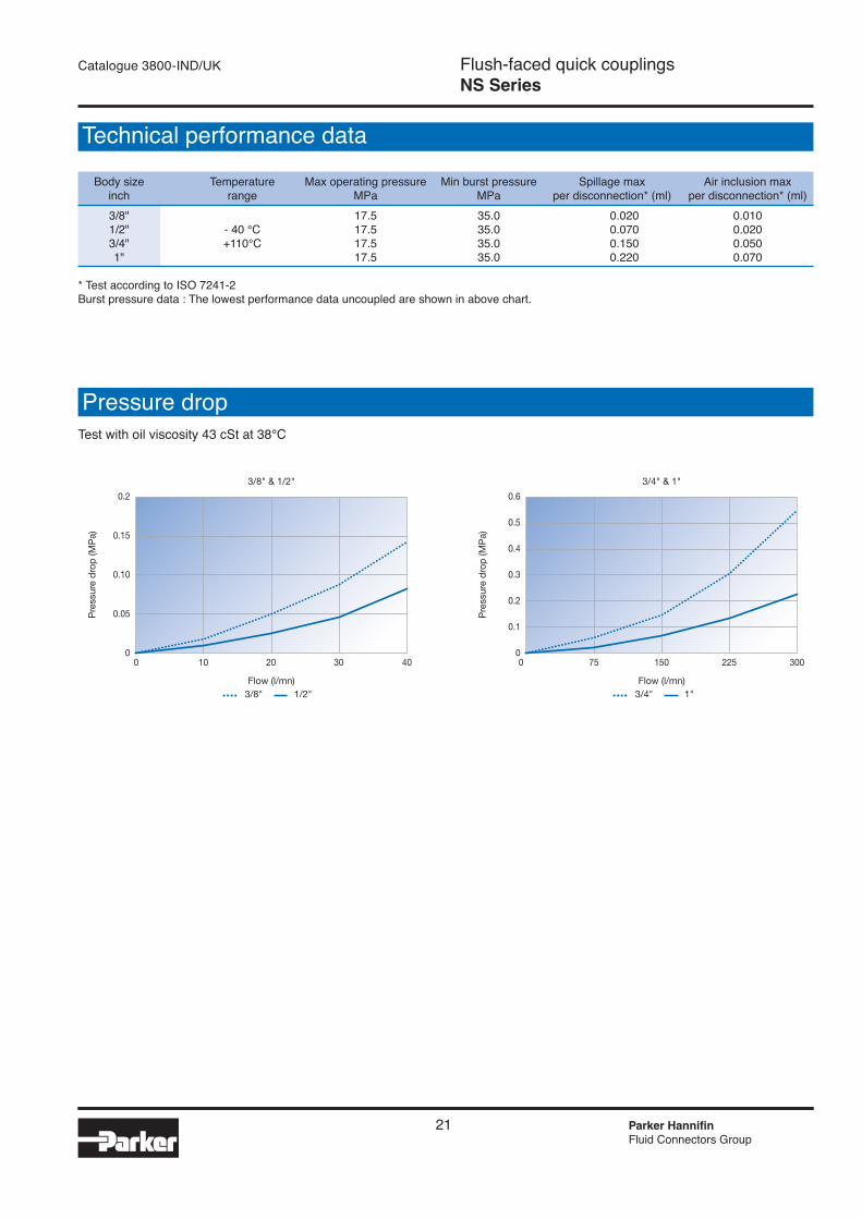
Test with oil viscosity 43 cSt at 38°C
0 10 20 30 40
Flow (l/mn)
0.2
0.15
0.10
0.05
0
Pre
ssur
e d
rop
(MP
a)
0 75 150 225 300
Flow (l/mn)
0.6
0.5
0.4
0.3
0.2
0.1
0
Pre
ssur
e d
rop
(MP
a)3/8" & 1/2" 3/4" & 1"
3/8" 1/2" 3/4" 1"
Body size Temperature Max operating pressure Min burst pressure Spillage max Air inclusion max inch range MPa MPa per disconnection* (ml) per disconnection* (ml)
3/8" 17.5 35.0 0.020 0.010 1/2" - 40 °C 17.5 35.0 0.070 0.020 3/4" +110°C 17.5 35.0 0.150 0.050 1" 17.5 35.0 0.220 0.070 * Test according to ISO 7241-2 Burst pressure data : The lowest performance data uncoupled are shown in above chart.
Pressure drop
Catalogue 3800-IND/UK Flush-faced quick couplings NS Series
22 Parker Hannifi n Fluid Connectors Group
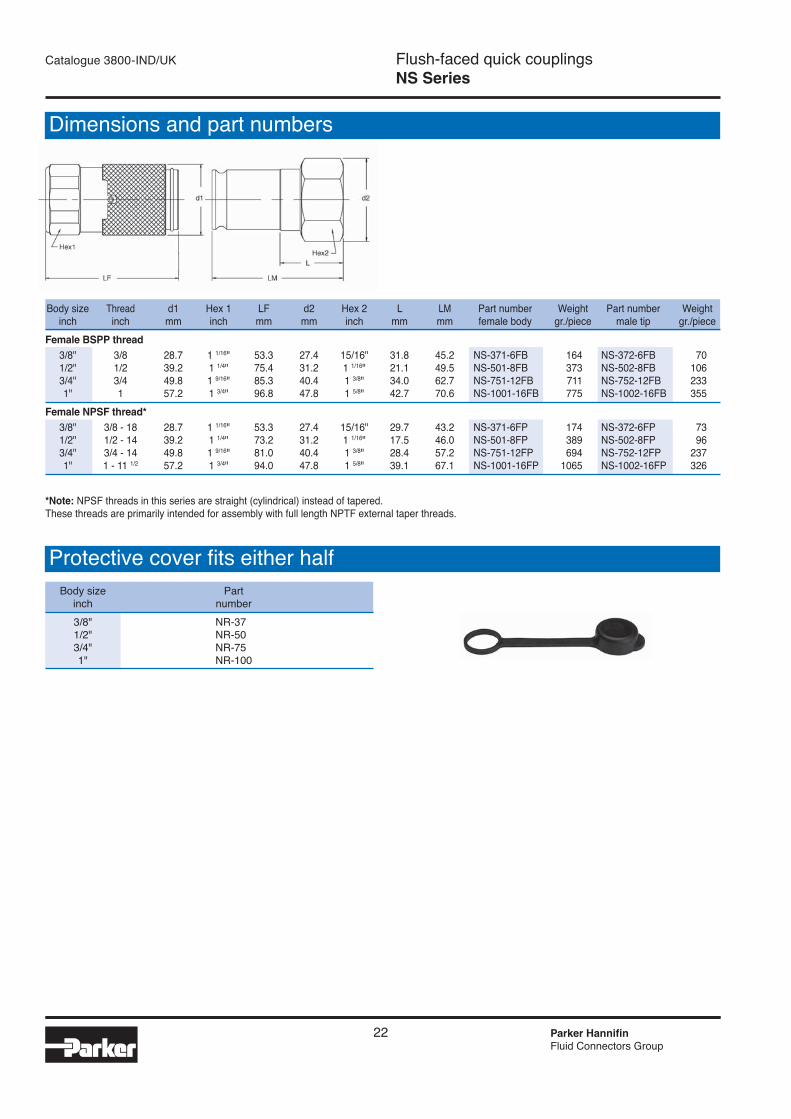
Dimensions and part numbers
Body size Thread d1 Hex 1 LF d2 Hex 2 L LM Part number Weight Part number Weight inch inch mm inch mm mm inch mm mm female body gr./piece male tip gr./piece
Female BSPP thread 3/8" 3/8 28.7 1 1/16" 53.3 27.4 15/16" 31.8 45.2 NS-371-6FB 164 NS-372-6FB 70 1/2" 1/2 39.2 1 1/4" 75.4 31.2 1 1/16" 21.1 49.5 NS-501-8FB 373 NS-502-8FB 106 3/4" 3/4 49.8 1 9/16" 85.3 40.4 1 3/8" 34.0 62.7 NS-751-12FB 711 NS-752-12FB 233 1" 1 57.2 1 3/4" 96.8 47.8 1 5/8" 42.7 70.6 NS-1001-16FB 775 NS-1002-16FB 355
Female NPSF thread* 3/8" 3/8 - 18 28.7 1 1/16" 53.3 27.4 15/16" 29.7 43.2 NS-371-6FP 174 NS-372-6FP 73 1/2" 1/2 - 14 39.2 1 1/4" 73.2 31.2 1 1/16" 17.5 46.0 NS-501-8FP 389 NS-502-8FP 96 3/4" 3/4 - 14 49.8 1 9/16" 81.0 40.4 1 3/8" 28.4 57.2 NS-751-12FP 694 NS-752-12FP 237 1" 1 - 11 1/2 57.2 1 3/4" 94.0 47.8 1 5/8" 39.1 67.1 NS-1001-16FP 1065 NS-1002-16FP 326
*Note: NPSF threads in this series are straight (cylindrical) instead of tapered.These threads are primarily intended for assembly with full length NPTF external taper threads.
Protective cover fi ts either half Body size Part inch number
3/8" NR-37 1/2" NR-50 3/4" NR-75 1" NR-100
Catalogue 3800-IND/UK Flush-faced quick couplings NSI Series
23 Parker Hannifi n Fluid Connectors Group
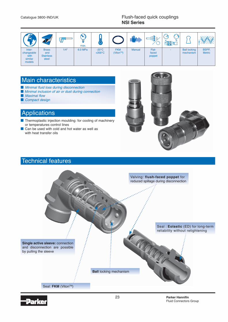
Main characteristics
Applications■ Thermoplastic injection moulding: for cooling of machinery or temperatures control lines■ Can be used with cold and hot water as well as with heat transfer oils
Technical features
Seal: FKM (VitonTM)
Valving: flush-faced poppet forreduced spillage during disconnection
■ Minimal fl uid loss during disconnection■ Minimal inclusion of air or dust during connection■ Maximal fl ow■ Compact design
Inter- Brass 1/4" 6.0 MPa -20°C FKM Manual Flat- - Ball locking BSPP, changeable and +200°C (VitonTM) faced mechanism Metric with Stainless poppet similar steel models
Single active sleeve: connection and disconnection are possible by pulling the sleeve
Ball locking mechanism
Seal : Eolastic (ED) for long-term reliability without retightening
Catalogue 3800-IND/UK Flush-faced quick couplings NSI Series
24 Parker Hannifi n Fluid Connectors Group
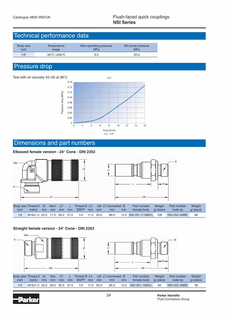
Technical performance data
Pressure drop
Test with oil viscosity 43 cSt at 38°C
Body size Temperature Max operating pressure Min burst pressure inch range MPa MPa
1/4" -20°C +200°C 6.0 20.0
0 2 4 6 8 10 12 14 16
Flow (l/mn)
0.16
0.14
0.12
0.10
0.08
0.06
0.04
0.02
0
Pre
ssur
e d
rop
(MP
a)
1/4"
1/4"
Dimensions and part numbersElbowed female version - 24° Cone - DIN 2353
Body size Thread A d1 Hex1 LF L Thread B L4 LM LT connected Ø Part number Weight Part number Weight inch metric mm mm mm mm BSPP mm mm mm mm female body gr./piece male tip gr./piece
1/4 M16x1.5 22.0 17.0 59.2 37.0 1/4 11.0 55.0 89.0 12.5 NSI-251-C16MCL 108 NSI-252-4MBE 48
Straight female version - 24° Cone - DIN 2353
Body size Thread A d1 Hex LF L Thread B L4 LM LT connected Ø Part number Weight Part number Weight inch metric mm mm mm mm BSPP mm mm mm mm female body gr./piece male tip gr./piece
1/4 M16x1.5 22.0 20.0 55.5 37.0 1/4 11.0 55.0 85.5 12.5 NSI-251-16MCL 84 NSI-252-4MBE 48
Catalogue 3800-IND/UK Flush-faced quick couplings FEM Series
25 Parker Hannifi n Fluid Connectors Group
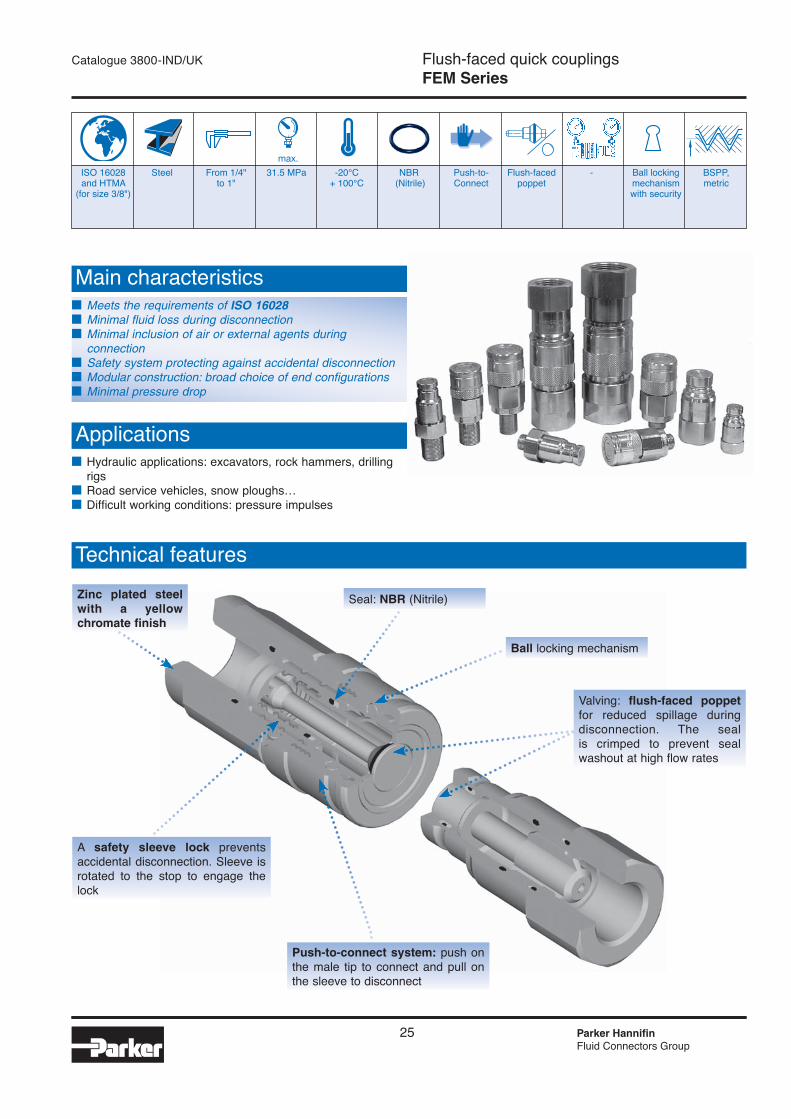
Main characteristics■ Meets the requirements of ISO 16028■ Minimal fl uid loss during disconnection■ Minimal inclusion of air or external agents during connection■ Safety system protecting against accidental disconnection■ Modular construction: broad choice of end confi gurations■ Minimal pressure drop
Applications■ Hydraulic applications: excavators, rock hammers, drilling rigs■ Road service vehicles, snow ploughs…■ Diffi cult working conditions: pressure impulses
Technical features
ISO 16028 Steel From 1/4" 31.5 MPa -20°C NBR Push-to- Flush-faced - Ball locking BSPP, and HTMA to 1" + 100°C (Nitrile) Connect poppet mechanism metric (for size 3/8") with security
Push-to-connect system: push on the male tip to connect and pull on the sleeve to disconnect
A safety sleeve lock prevents accidental disconnection. Sleeve is rotated to the stop to engage the lock
Seal: NBR (Nitrile)Zinc plated steel with a yellow chromate fi nish
Ball locking mechanism
Valving: fl ush-faced poppet for reduced spillage during disconnection. The seal is crimped to prevent seal washout at high fl ow rates
Catalogue 3800-IND/UK Flush-faced quick couplings FEM Series
26 Parker Hannifi n Fluid Connectors Group
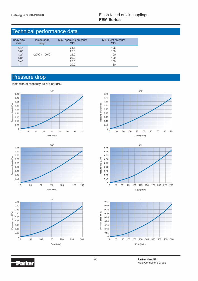
Pressure drop
Technical performance data
Body size Temperature Max. operating pressure Min. burst pressure inch range MPa MPa
1/4" 31.5 126 3/8" 25.0 100 1/2" -20°C + 100°C 25.0 100 5/8" 25.0 100 3/4" 25.0 100 1" 20.0 80
Tests with oil viscosity 43 cSt at 38°C.
Flow (l/min)
1/4"
Pre
ssur
e dr
op (
MP
a)
Flow (l/min)
1/2"
Pre
ssur
e dr
op (
MP
a)
Flow (l/min)
3/4"
Pre
ssur
e dr
op (
MP
a)
Flow (l/min)
1"
Pre
ssur
e dr
op (
MP
a)
Flow (l/min)
5/8"
Pre
ssur
e dr
op (
MP
a)
Flow (l/min)
3/8"
Pre
ssur
e dr
op (
MP
a)
Catalogue 3800-IND/UK Flush-faced quick couplings FEM Series
27 Parker Hannifi n Fluid Connectors Group
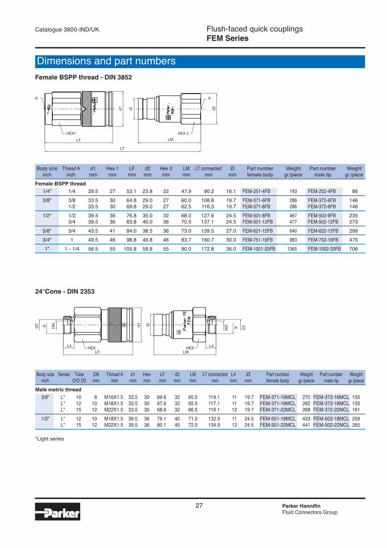
Dimensions and part numbers
Female BSPP thread - DIN 3852
Body size Series Tube DN Thread A d1 Hex LF d2 LM LT connected L4 Ø Part number Weight Part number Weight inch O/D D2 mm mm mm mm mm mm mm mm mm mm female body gr./piece male tip gr./piece
Male metric thread 3/8" L* 10 8 M16X1.5 33.5 30 69.6 32 65.5 119.1 11 19.7 FEM-371-16MCL 270 FEM-372-16MCL 155 L* 12 10 M18X1.5 33.5 30 67.6 32 65.5 117.1 11 19.7 FEM-371-18MCL 262 FEM-372-18MCL 155 L* 15 12 M22X1.5 33.5 30 68.6 32 66.5 119.1 12 19.7 FEM-371-22MCL 268 FEM-372-22MCL 161
1/2" L* 12 10 M18X1.5 39.5 36 79.1 40 71.0 132.9 11 24.5 FEM-501-18MCL 433 FEM-502-18MCL 259 L* 15 12 M22X1.5 39.5 36 80.1 40 72.0 134.9 12 24.5 FEM-501-22MCL 441 FEM-502-22MCL 265
* Light series
Body size Thread A d1 Hex 1 LF d2 Hex 2 LM LT connected Ø Part number Weight Part number Weight inch inch mm mm mm mm mm mm mm mm female body gr./piece male tip gr./piece
Female BSPP thread 1/4" 1/4 29.5 27 53.1 23.8 22 47.9 90.2 16.1 FEM-251-4FB 193 FEM-252-4FB 86
3/8" 3/8 33.5 30 64.8 29.0 27 60.0 108.8 19.7 FEM-371-6FB 286 FEM-372-6FB 146 1/2 33.5 30 69.8 29.0 27 62.5 116.3 19.7 FEM-371-8FB 286 FEM-372-8FB 146
1/2" 1/2 39.5 36 76.8 35.0 32 68.0 127.6 24.5 FEM-501-8FB 467 FEM-502-8FB 235 3/4 39.5 36 83.8 40.0 36 70.5 137.1 24.5 FEM-501-12FB 477 FEM-502-12FB 273
5/8" 3/4 43.5 41 84.0 38.5 36 73.0 139.5 27.0 FEM-621-12FB 640 FEM-622-12FB 299
3/4" 1 49.5 46 98.8 49.8 46 83.7 160.7 30.0 FEM-751-16FB 983 FEM-752-16FB 475
1" 1 - 1/4 56.5 55 105.8 59.8 55 90.0 172.8 36.0 FEM-1001-20FB 1365 FEM-1002-20FB 706
24°Cone - DIN 2353
Catalogue 3800-IND/UK Flush-faced quick couplings FEM Series
28 Parker Hannifi n Fluid Connectors Group
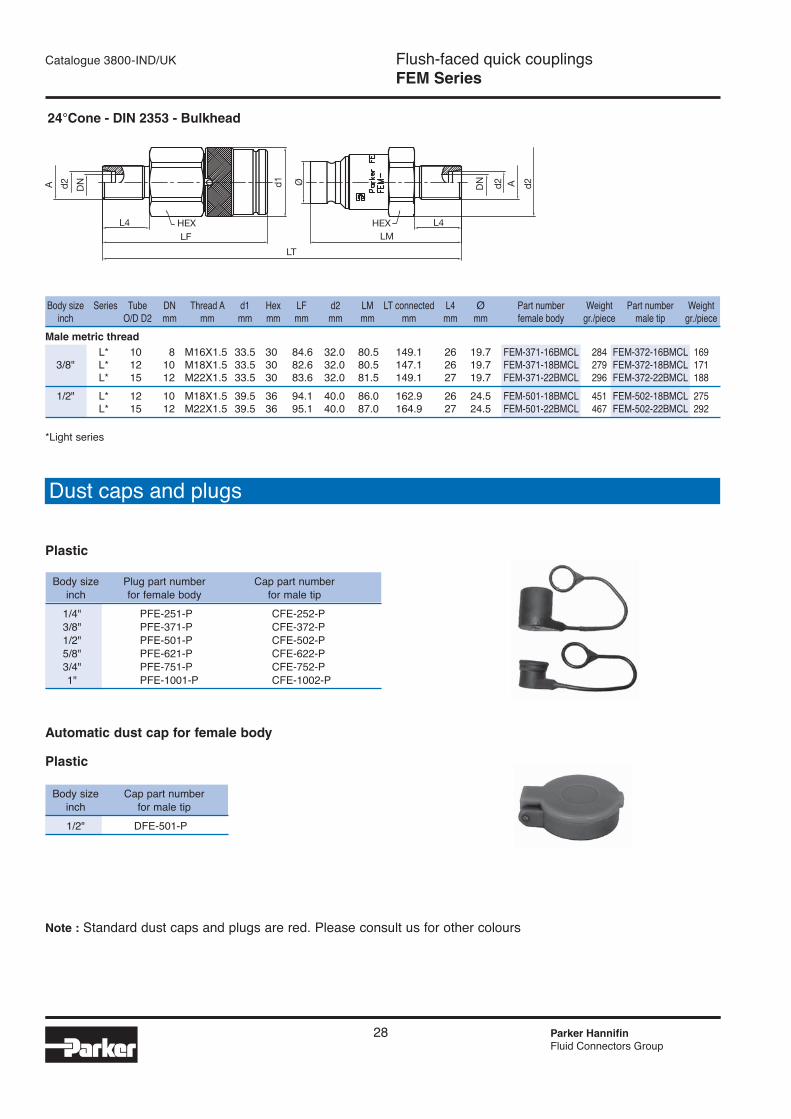
24°Cone - DIN 2353 - Bulkhead
Dust caps and plugs
Body size Plug part number Cap part number inch for female body for male tip
1/4" PFE-251-P CFE-252-P 3/8" PFE-371-P CFE-372-P 1/2" PFE-501-P CFE-502-P 5/8" PFE-621-P CFE-622-P 3/4" PFE-751-P CFE-752-P 1" PFE-1001-P CFE-1002-P
Plastic
Body size Cap part number inch for male tip
1/2" DFE-501-P
Automatic dust cap for female body
Plastic
Note : Standard dust caps and plugs are red. Please consult us for other colours
Body size Series Tube DN Thread A d1 Hex LF d2 LM LT connected L4 Ø Part number Weight Part number Weight inch O/D D2 mm mm mm mm mm mm mm mm mm mm female body gr./piece male tip gr./piece
Male metric thread L* 10 8 M16X1.5 33.5 30 84.6 32.0 80.5 149.1 26 19.7 FEM-371-16BMCL 284 FEM-372-16BMCL 169 3/8" L* 12 10 M18X1.5 33.5 30 82.6 32.0 80.5 147.1 26 19.7 FEM-371-18BMCL 279 FEM-372-18BMCL 171 L* 15 12 M22X1.5 33.5 30 83.6 32.0 81.5 149.1 27 19.7 FEM-371-22BMCL 296 FEM-372-22BMCL 188
1/2" L* 12 10 M18X1.5 39.5 36 94.1 40.0 86.0 162.9 26 24.5 FEM-501-18BMCL 451 FEM-502-18BMCL 275 L* 15 12 M22X1.5 39.5 36 95.1 40.0 87.0 164.9 27 24.5 FEM-501-22BMCL 467 FEM-502-22BMCL 292
* Light series
Catalogue 3800-IND/UK Flush-faced quick couplings FS Series
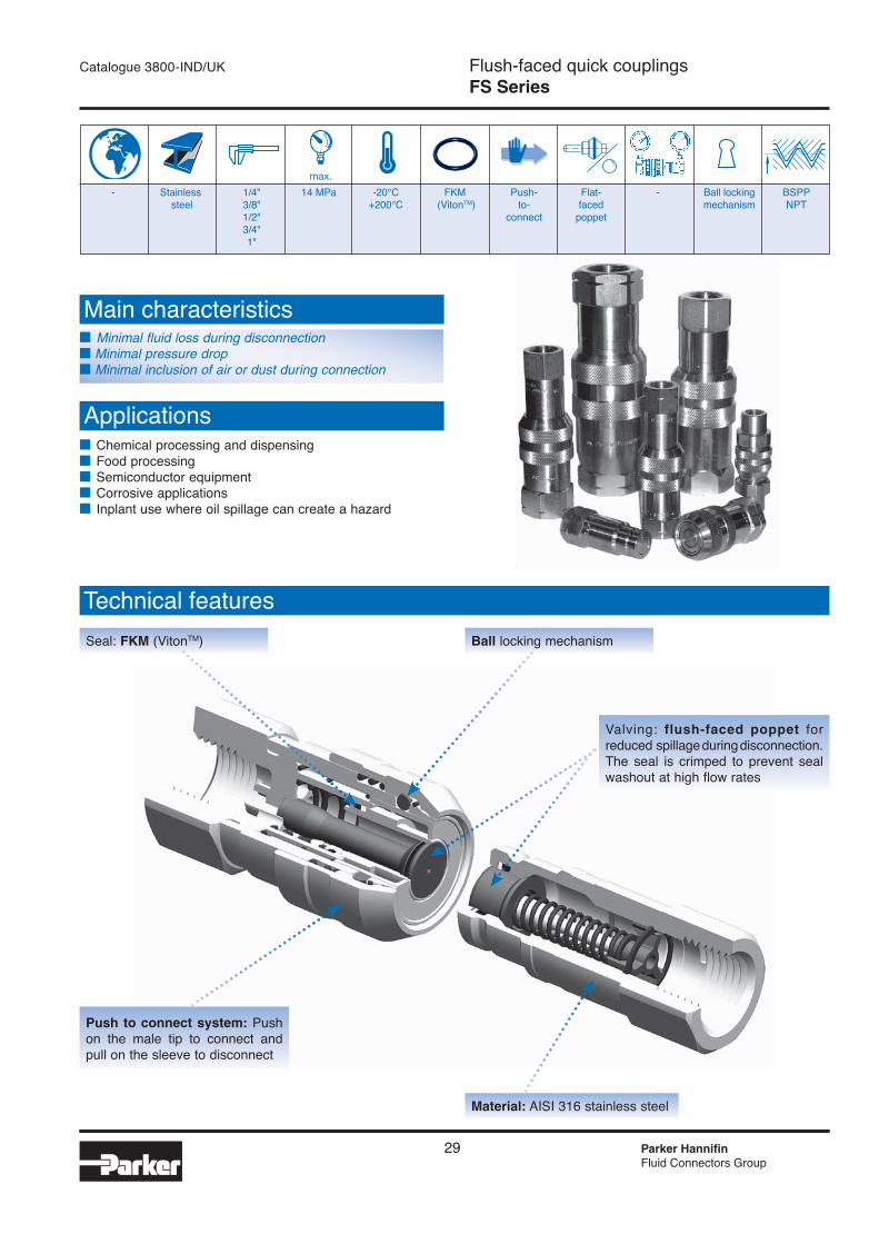
29 Parker Hannifi n Fluid Connectors Group
Main characteristics
Applications■ Chemical processing and dispensing■ Food processing■ Semiconductor equipment■ Corrosive applications ■ Inplant use where oil spillage can create a hazard
Technical features
Seal: FKM (VitonTM) Ball locking mechanism
Valving: flush-faced poppet for reduced spillage during disconnection. The seal is crimped to prevent seal washout at high fl ow rates
Push to connect system: Push on the male tip to connect and pull on the sleeve to disconnect
Material: AISI 316 stainless steel
■ Minimal fl uid loss during disconnection■ Minimal pressure drop■ Minimal inclusion of air or dust during connection
- Stainless 1/4" 14 MPa -20°C FKM Push- Flat- - Ball locking BSPP steel 3/8" +200°C (VitonTM) to- faced mechanism NPT 1/2" connect poppet 3/4" 1"
Catalogue 3800-IND/UK Flush-faced quick couplings FS Series
30 Parker Hannifi n Fluid Connectors Group
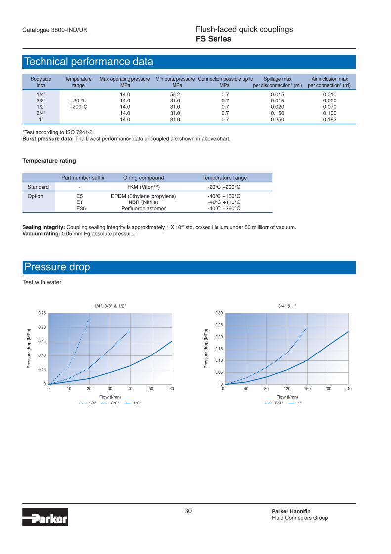
Body size Temperature Max operating pressure Min burst pressure Connection possible up to Spillage max Air inclusion max inch range MPa MPa MPa per disconnection* (ml) per connection* (ml)
1/4" 14.0 55.2 0.7 0.015 0.010 3/8" - 20 °C 14.0 31.0 0.7 0.015 0.020 1/2" +200°C 14.0 31.0 0.7 0.020 0.070 3/4" 14.0 31.0 0.7 0.150 0.100 1" 14.0 31.0 0.7 0.250 0.182 *Test according to ISO 7241-2 Burst pressure data: The lowest performance data uncoupled are shown in above chart.
Technical performance data
Pressure dropTest with water
Part number suffi x O-ring compound Temperature range
Standard - FKM (VitonTM) -20°C +200°C
Option E5 EPDM (Ethylene propylene) -40°C +150°C E1 NBR (Nitrile) -40°C +110°C E35 Perfl uoroelastomer -40°C +260°C
Sealing integrity: Coupling sealing integrity is approximately 1 X 10⁻⁶ std. cc/sec Helium under 50 millitorr of vacuum.Vacuum rating: 0.05 mm Hg absolute pressure.
Temperature rating
0 10 20 30 40 50 60
Flow (l/mn)
0.25
0.20
0.15
0.10
0.05
0
Pre
ssur
e d
rop
(MP
a)
0 40 80 120 160 200 240
Flow (l/mn)
0.30
0.25
0.20
0.15
0.10
0.05
0
Pre
ssur
e d
rop
(MP
a)
1/4", 3/8" & 1/2" 3/4" & 1"
3/8" 1/2"1/4" 3/4" 1"
Catalogue 3800-IND/UK Flush-faced quick couplings FS Series
31 Parker Hannifi n Fluid Connectors Group
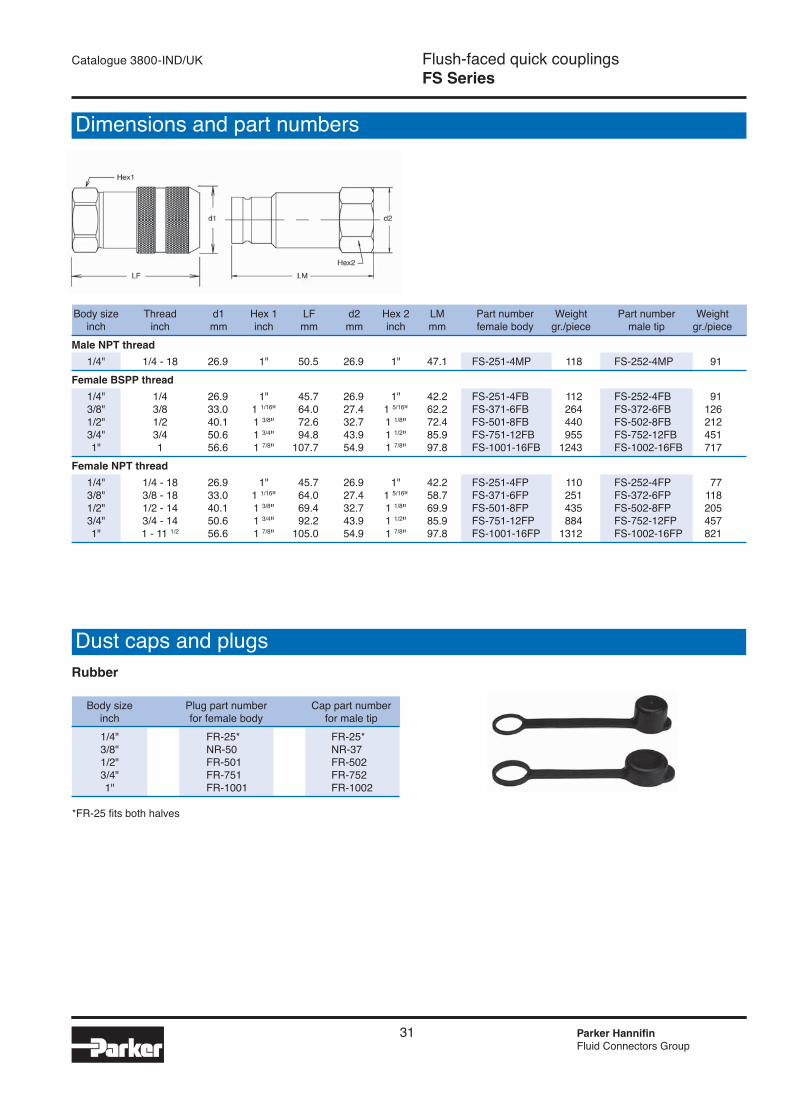
Dimensions and part numbers
Body size Thread d1 Hex 1 LF d2 Hex 2 LM Part number Weight Part number Weight inch inch mm inch mm mm inch mm female body gr./piece male tip gr./piece
Male NPT thread
1/4" 1/4 - 18 26.9 1" 50.5 26.9 1" 47.1 FS-251-4MP 118 FS-252-4MP 91
Female BSPP thread
1/4" 1/4 26.9 1" 45.7 26.9 1" 42.2 FS-251-4FB 112 FS-252-4FB 91 3/8" 3/8 33.0 1 1/16" 64.0 27.4 1 5/16" 62.2 FS-371-6FB 264 FS-372-6FB 126 1/2" 1/2 40.1 1 3/8" 72.6 32.7 1 1/8" 72.4 FS-501-8FB 440 FS-502-8FB 212 3/4" 3/4 50.6 1 3/4" 94.8 43.9 1 1/2" 85.9 FS-751-12FB 955 FS-752-12FB 451 1" 1 56.6 1 7/8" 107.7 54.9 1 7/8" 97.8 FS-1001-16FB 1243 FS-1002-16FB 717
Female NPT thread
1/4" 1/4 - 18 26.9 1" 45.7 26.9 1" 42.2 FS-251-4FP 110 FS-252-4FP 77 3/8" 3/8 - 18 33.0 1 1/16" 64.0 27.4 1 5/16" 58.7 FS-371-6FP 251 FS-372-6FP 118 1/2" 1/2 - 14 40.1 1 3/8" 69.4 32.7 1 1/8" 69.9 FS-501-8FP 435 FS-502-8FP 205 3/4" 3/4 - 14 50.6 1 3/4" 92.2 43.9 1 1/2" 85.9 FS-751-12FP 884 FS-752-12FP 457 1" 1 - 11 1/2 56.6 1 7/8" 105.0 54.9 1 7/8" 97.8 FS-1001-16FP 1312 FS-1002-16FP 821
Dust caps and plugsRubber
Body size Plug part number Cap part number inch for female body for male tip
1/4" FR-25* FR-25* 3/8" NR-50 NR-37 1/2" FR-501 FR-502 3/4" FR-751 FR-752 1" FR-1001 FR-1002
*FR-25 fi ts both halves
Catalogue 3800-IND/UK Flush-faced quick couplings PF Series
32 Parker Hannifi n Fluid Connectors Group
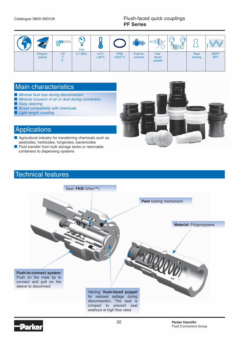
Main characteristics
Applications■ Agricultural industry for transferring chemicals such as pesticides, herbicides, fungicides, bactericides■ Fluid transfer from bulk storage tanks or returnable containers to dispensing systems
Technical features
Valving: fl ush-faced poppet for reduced spillage during disconnection. The seal is crimped to prevent seal washout at high fl ow rates
Seal: FKM (Viton™)
Push-to-connect system: Push on the male tip to connect and pull on the sleeve to disconnect
Material: Polypropylene
Pawl locking mechanism
■ Minimal fl uid loss during disconnection■ Minimal inclusion of air or dust during connection■ Easy cleaning■ Broad compatibility with chemicals■ Light weight coupling
- Polypro- 1/2" 0.7 MPa +4°C FKM Push-to- Flat- - Pawl BSPP pylene 1" + 60°C (VitonTM) connect faced locking NPT 2" poppet

Catalogue 3800-IND/UK Flush-faced quick couplings PF Series
33 Parker Hannifi n Fluid Connectors Group
Technical performance data
Pressure drop
Dimensions and part numbers
Body size Temperature Rated pressure (MPa) Max force Max force Spillage max Rated fl ow inch range at 20°C to connect to disconnect per disconnection* (l/min) daN daN (ml)
1/2" +4°C 0.7 14.2 5.3 0.14 45 1" +60°C 0.4 24.0 7.5 1 75 2" 0.7 18.2 7.5 9 190
Vacuum data: 696 mm Hg both connected and disconnected.Caution: The female coupler and nipple must be replaced before the date shown on the product, or sooner if excessive wear, seal deterioration, leakage, corrosion, or other damage is apparent, whichever is earlier.
Test with water
Couplers
0 15 30 45 60 75
Flow (l/mn)
0.25
0.20
0.15
0.10
0.05
0
Pre
ssur
e d
rop
(MP
a)
0 40 80 120 160 200 240
Flow (l/mn)
0.35
0.30
0.25
0.20
0.15
0.10
0.05
0
Pre
ssur
e d
rop
(MP
a)
1/2" 1"
1/2" 1"
0 1 2 3 4 5 6 7 8 9 10 11 12
Flow (l/mn)
0.08
0.07
0.06
0.05
0.04
0.03
0.02
0.01
0
Pre
ssur
e d
rop
(MP
a)
2"
2"
Body size Thread d1 Hex1 LF Part number Weight inch inch mm inch mm female body gr./piece
Female NPT thread
1/2" 1/2 - 14 47.8 1 3/8" 76.7 PF-501-8FP 84
Catalogue 3800-IND/UK Flush-faced quick couplings PF Series
34 Parker Hannifi n Fluid Connectors Group
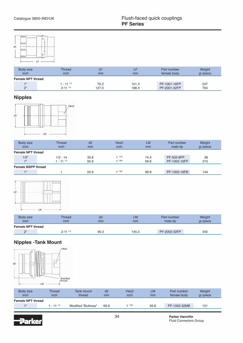
Nipples -Tank Mount
Body size Thread d1 LF Part number Weight inch inch mm mm female body gr./piece
Female NPT thread
1" 1 - 11 1/2 76.2 101.3 PF-1001-16FP 247 2" 2-11 1/2 127.0 168.4 PF-2001-32FP 794
Nipples
Body size Thread d2 Hex2 LM Part number Weight inch inch mm inch mm male tip gr./piece
Female NPT thread
1/2" 1/2 - 14 33.8 1 1/4" 74.4 PF-502-8FP 38 1" 1 - 11 1/2 55.9 1 7/8" 99.8 PF-1002-16FP 210
Female BSPP thread
1" 1 55.9 1 7/8" 99.8 PF-1002-16FB 144
Body size Thread d2 LM Part number Weight inch inch mm mm male tip gr./piece
Female NPT thread
2" 2-11 1/2 90.2 145.0 PF-2002-32FP 340
Body size Thread Tank mount d2 Hex2 LM Part number Weight inch inch thread mm inch mm female body gr./piece
Female NPT thread
1" 1 - 11 1/2 Modifi ed "Buttress" 69.9 1 7/8" 99.8 PF-1002-32MB 151
Catalogue 3800-IND/UK Flush-faced quick couplings PF Series
35 Parker Hannifi n Fluid Connectors Group
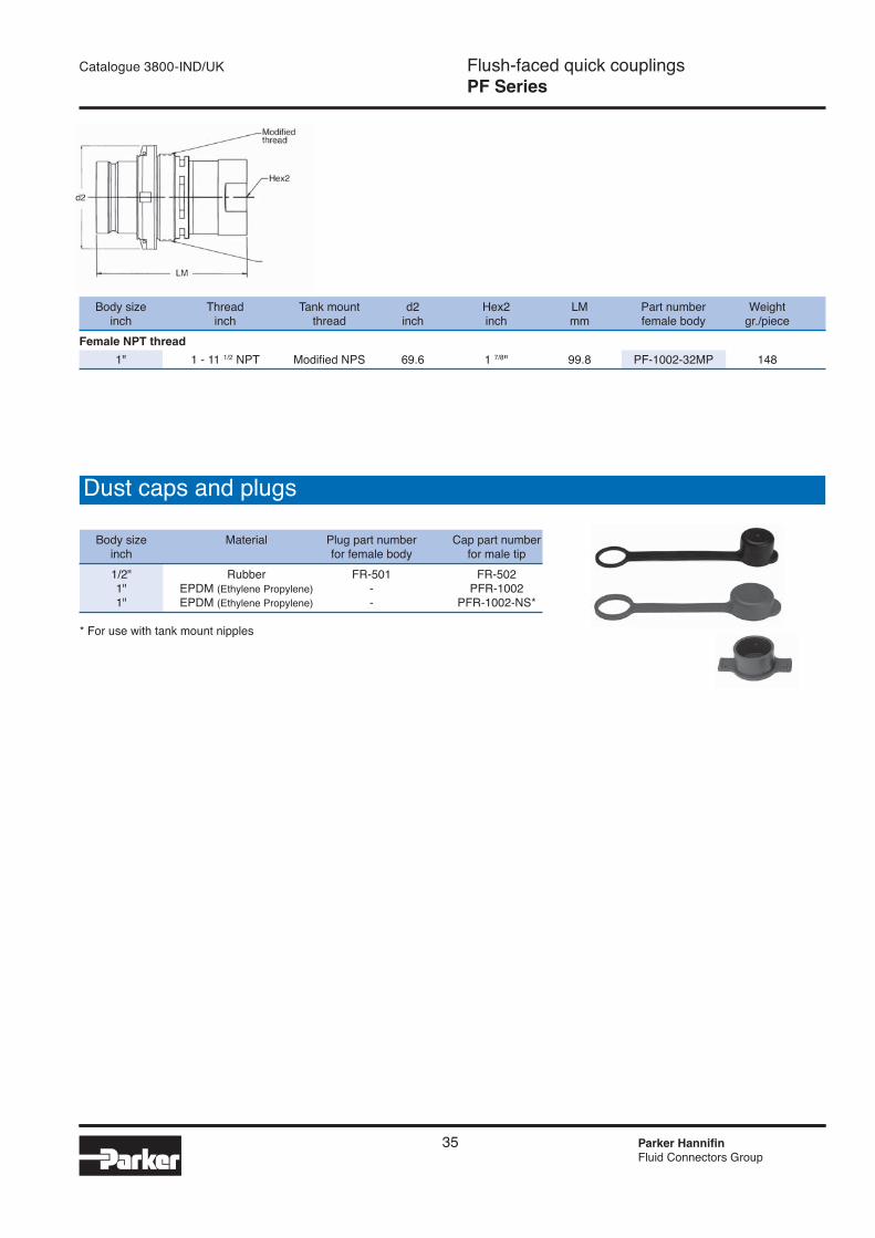
Body size Thread Tank mount d2 Hex2 LM Part number Weight inch inch thread inch inch mm female body gr./piece
Female NPT thread
1" 1 - 11 1/2 NPT Modifi ed NPS 69.6 1 7/8" 99.8 PF-1002-32MP 148
Body size Material Plug part number Cap part number inch for female body for male tip
1/2" Rubber FR-501 FR-502 1" EPDM (Ethylene Propylene) - PFR-1002 1" EPDM (Ethylene Propylene) - PFR-1002-NS* * For use with tank mount nipples
Dust caps and plugs
Catalogue 3800-IND/UK Screw type quick couplings 6100 Series
36 Parker Hannifi n Fluid Connectors Group
Main characteristics
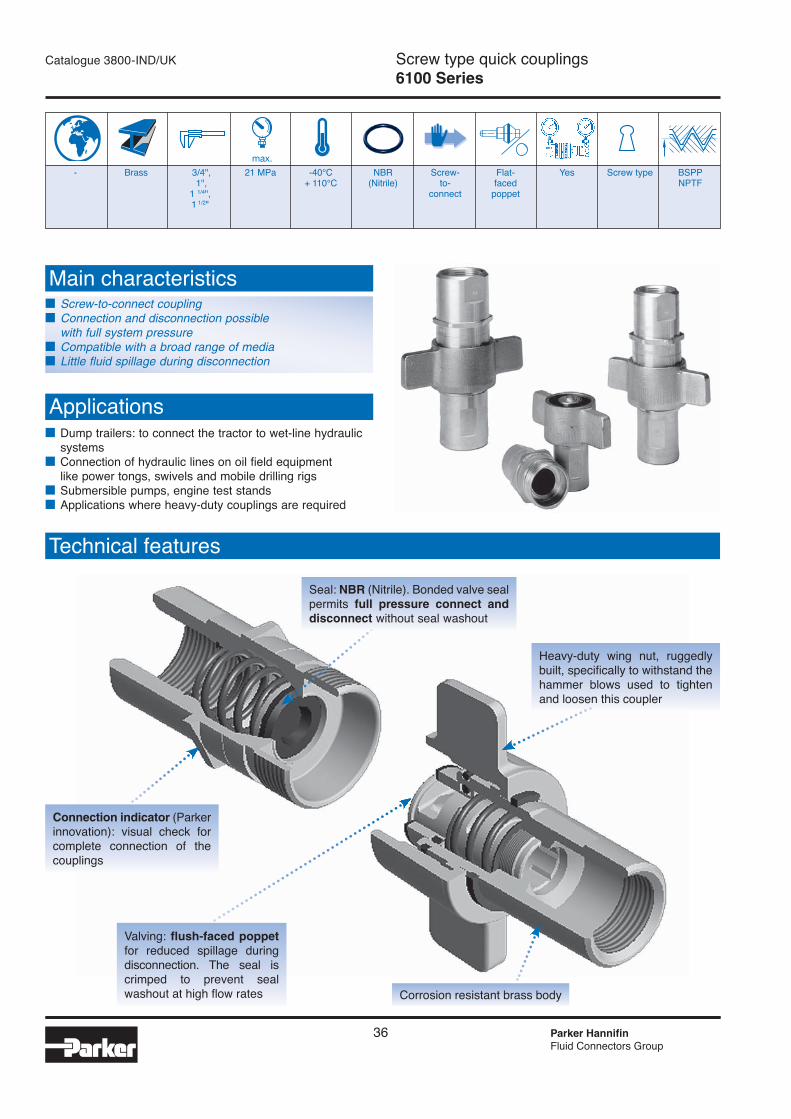
Applications■ Dump trailers: to connect the tractor to wet-line hydraulic systems■ Connection of hydraulic lines on oil fi eld equipment like power tongs, swivels and mobile drilling rigs■ Submersible pumps, engine test stands■ Applications where heavy-duty couplings are required
Technical features
■ Screw-to-connect coupling■ Connection and disconnection possible with full system pressure■ Compatible with a broad range of media■ Little fl uid spillage during disconnection
- Brass 3/4", 21 MPa -40°C NBR Screw- Flat- Yes Screw type BSPP 1", + 110°C (Nitrile) to- faced NPTF 1 1/4", connect poppet 1 1/2"
Connection indicator (Parker innovation): visual check for complete connection of the couplings
Valving: fl ush-faced poppet for reduced spillage during disconnection. The seal is crimped to prevent seal washout at high fl ow rates
Seal: NBR (Nitrile). Bonded valve seal permits full pressure connect and disconnect without seal washout
Heavy-duty wing nut, ruggedly built, specifi cally to withstand the hammer blows used to tighten and loosen this coupler
Corrosion resistant brass body
Catalogue 3800-IND/UK Screw type quick couplings 6100 Series
37 Parker Hannifi n Fluid Connectors Group
Technical performance data
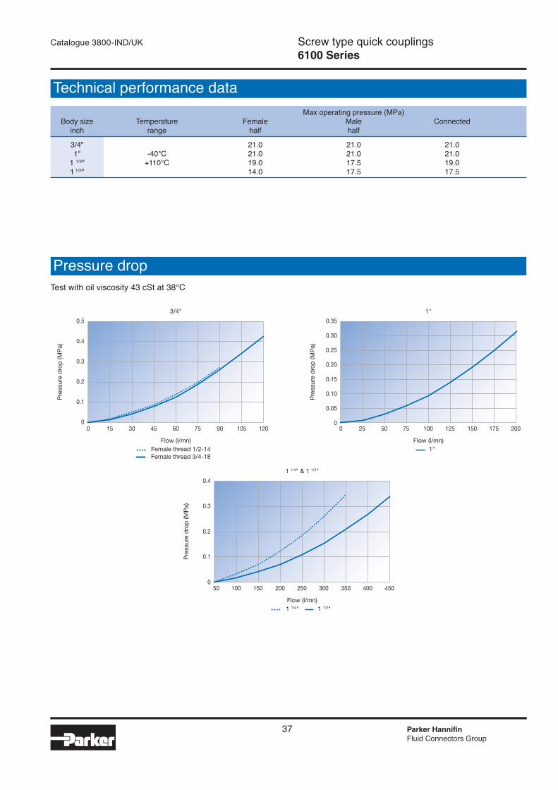
Pressure dropTest with oil viscosity 43 cSt at 38°C
Max operating pressure (MPa) Body size Temperature Female Male Connected inch range half half
3/4" 21.0 21.0 21.0 1" -40°C 21.0 21.0 21.0 1 1/4" +110°C 19.0 17.5 19.0 1 1/2" 14.0 17.5 17.5
50 100 150 200 250 300 350 400 450
Flow (l/mn)
0.4
0.3
0.2
0.1
0
Pre
ssur
e d
rop
(MP
a)
1 1/4" & 1 1/2"
0 15 30 45 60 75 90 105 120
Flow (l/mn)
0.5
0.4
0.3
0.2
0.1
0
Pre
ssur
e d
rop
(MP
a)
0 25 50 75 100 125 150 175 200
Flow (l/mn)
0.35
0.30
0.25
0.20
0.15
0.10
0.05
0
Pre
ssur
e d
rop
(MP
a)3/4" 1"
1"
1 1/4" 1 1/2"
Female thread 1/2-14Female thread 3/4-18
Catalogue 3800-IND/UK Screw type quick couplings 6100 Series
38 Parker Hannifi n Fluid Connectors Group
Dimensions and part numbers
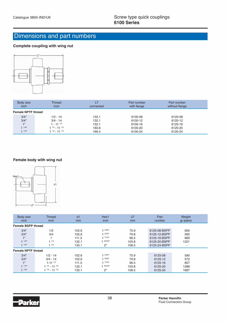
Complete coupling with wing nut
Female body with wing nut
Body size Thread LT Part number Part number inch inch connected with fl ange without fl ange
Female NPTF thread
3/4" 1/2 - 14 132.1 6100-08 6120-08 3/4" 3/4 - 14 132.1 6100-12 6120-12 1" 1 - 11 1/2 152.1 6100-16 6120-16 1 1/4" 1 1/4 - 11 1/2 160.8 6100-20 6120-20 1 1/2" 1 1/2 - 11 1/2 166.4 6100-24 6120-24
Body size Thread d1 Hex1 LF Part Weight inch inch mm inch mm number gr./piece
Female BSPP thread
3/4" 1/2 102.6 1 5/32" 75.9 6125-08-BSPP 600 3/4" 3/4 102.6 1 5/32" 79.8 6125-12-BSPP 560 1" 1 111.3 1 7/16" 96.5 6125-16-BSPP 869 1 1/4" 1 1/4 132.1 1 25/32" 103.8 6125-20-BSPP 1221 1 1/2" 1 1/2 135.1 2" 108.5 6125-24-BSPP -
Female NPTF thread
3/4" 1/2 - 14 102.6 1 5/32" 75.9 6125-08 590 3/4" 3/4 - 14 102.6 1 5/32" 79.8 6125-12 572 1" 1-11 1/2 111.3 1 7/16" 96.5 6125-16 857 1 1/4" 1 1/4 - 11 1/2 132.1 1 25/32" 103.8 6125-20 1288 1 1/2" 1 1/2 - 11 1/2 135.1 2" 108.5 6125-24 1687
Catalogue 3800-IND/UK Screw type quick couplings 6100 Series
39 Parker Hannifi n Fluid Connectors Group
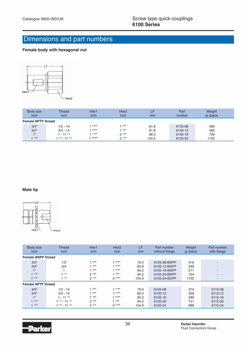
Dimensions and part numbers
Female body with hexagonal nut
Male tip
Body size Thread Hex1 Hex2 LF Part Weight inch inch inch inch mm number gr./piece
Female NPTF thread
3/4" 1/2 - 14 1 5/32" 1 3/4" 81.8 6135-08 485 3/4" 3/4 - 14 1 5/32" 1 3/4" 81.8 6135-12 485 1" 1 - 11 1/2 1 7/16" 2 1/8" 98.3 6135-16 739 1 1/4" 1 1/4 - 11 1/2 1 25/32" 2 1/2" 105.6 6135-20 1120
Body size Thread Hex1 Hex2 LF Part number Weight Part number inch inch inch inch mm without fl ange gr./piece with fl ange
Female BSPP thread
3/4" 1/2 1 5/8" 1 3/16" 79.0 6105-08-BSPP 416 - 3/4" 3/4 1 5/8" 1 3/16" 83.8 6105-12-BSPP 349 - 1" 1 1 7/8" 1 9/16" 90.2 6105-16-BSPP 571 - 1 1/4" 1 1/4 2 1/8" 1 7/8" 94.2 6105-20-BSPP 754 - 1 1/2" 1 1/2 2 1/2" 2 3/16" 104.6 6105-24-BSPP 1155 -
Female NPTF thread
3/4" 1/2 - 14 1 5/8" 1 3/16" 79.0 6105-08 374 6115-08 3/4" 3/4 - 14 1 5/8" 1 3/16" 82.0 6105-12 358 6115-12 1" 1 - 11 1/2 1 7/8" 1 9/16" 90.2 6105-16 589 6115-16 1 1/4" 1 1/4 - 11 1/2 2 1/8" 1 7/8" 94.2 6105-20 741 6115-20 1 1/2" 1 1/2 - 11 1/2 2 1/2" 2 3/16" 104.6 6105-24 988 6115-24
Catalogue 3800-IND/UK Screw type quick couplings 6100 Series
40 Parker Hannifi n Fluid Connectors Group
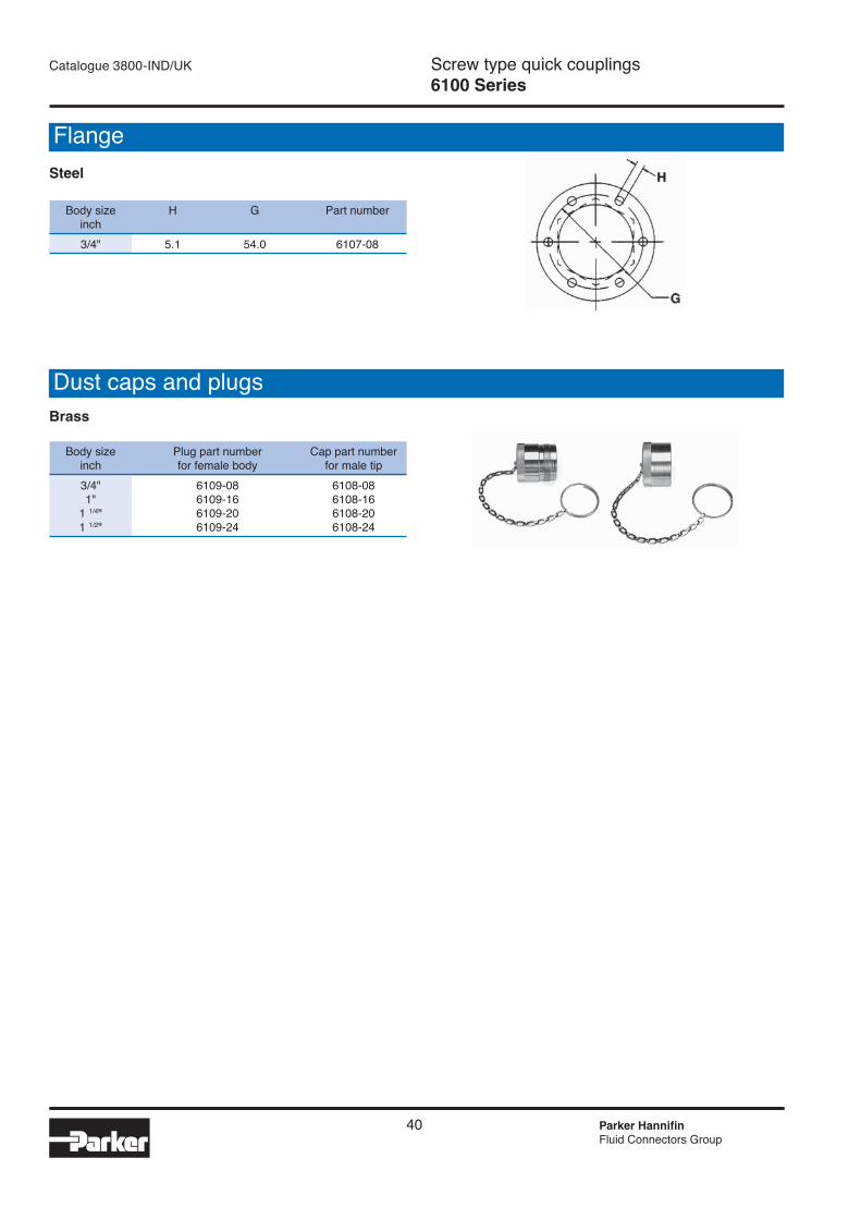
Flange
Body size H G Part number inch
3/4" 5.1 54.0 6107-08
Dust caps and plugs
Steel
Brass
Body size Plug part number Cap part number inch for female body for male tip
3/4" 6109-08 6108-08 1" 6109-16 6108-16 1 1/4" 6109-20 6108-20 1 1/2" 6109-24 6108-24
Catalogue 3800-IND/UK High pressure quick couplings CM Series
41 Parker Hannifi n Fluid Connectors Group
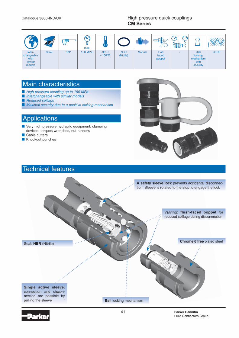
Main characteristics
Applications■ Very high pressure hydraulic equipment, clamping devices, torques wrenches, nut runners■ Cable cutters■ Knockout punches
Technical features
A safety sleeve lock prevents accidental disconnec-tion. Sleeve is rotated to the stop to engage the lock
Seal: NBR (Nitrile)
Single active sleeve: connection and discon-nection are possible by pulling the sleeve
Chrome 6 free plated steel
Valving: flush-faced poppet for reduced spillage during disconnection
Ball locking mechanism
■ High pressure coupling up to 150 MPa■ Interchangeable with similar models■ Reduced spillage■ Maximal security due to a positive locking mechanism
Inter- Steel 1/4" 150 MPa -30°C NBR Manual Flat- - Ball BSPP changeable + 100°C (Nitrile) faced locking with poppet mechanism similar with models security
Catalogue 3800-IND/UK High pressure quick couplings CM Series
42 Parker Hannifi n Fluid Connectors Group
0 2 4 6 8 10 12
Flow rate in (l/mn)
0.14
0.12
0.10
0.08
0.06
0.04
0.02
0
Pre
ssur
e d
rop
(MP
a)
1/4"
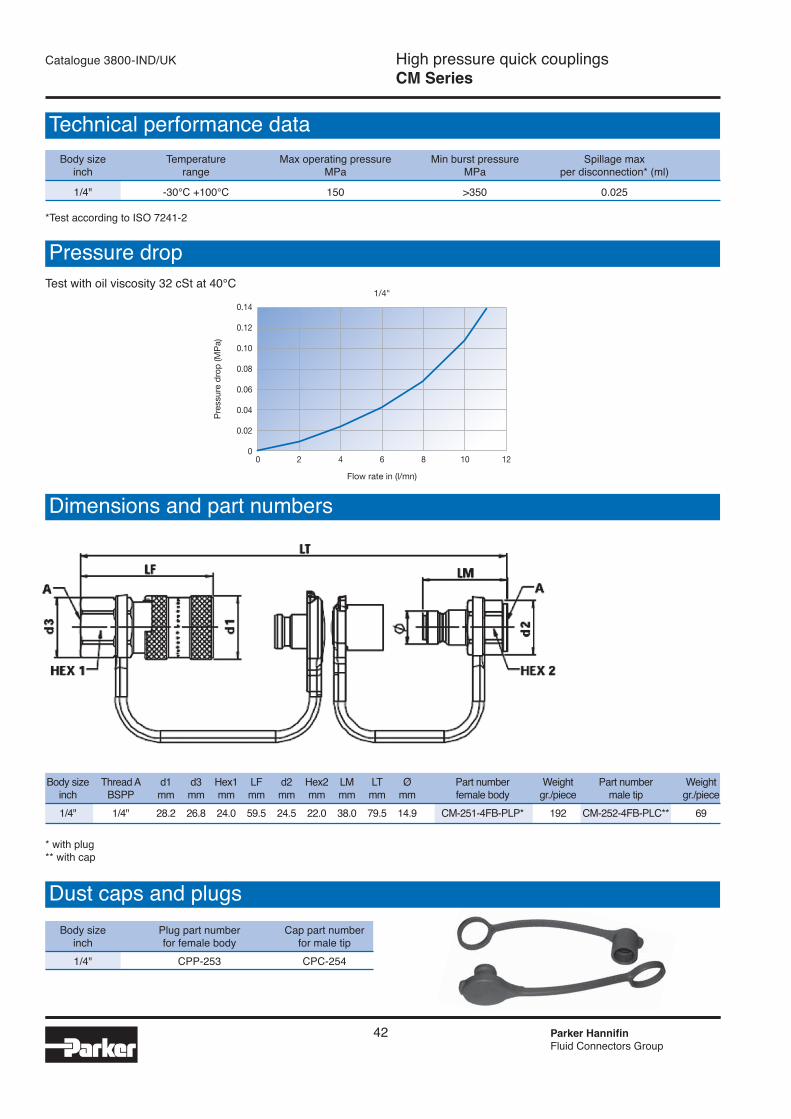
Technical performance data
Body size Temperature Max operating pressure Min burst pressure Spillage max inch range MPa MPa per disconnection* (ml)
1/4" -30°C +100°C 150 >350 0.025 *Test according to ISO 7241-2
Pressure drop
Dimensions and part numbers
Dust caps and plugs
Test with oil viscosity 32 cSt at 40°C
Body size Plug part number Cap part number inch for female body for male tip
1/4" CPP-253 CPC-254
Body size Thread A d1 d3 Hex1 LF d2 Hex2 LM LT Ø Part number Weight Part number Weight inch BSPP mm mm mm mm mm mm mm mm mm female body gr./piece male tip gr./piece
1/4" 1/4" 28.2 26.8 24.0 59.5 24.5 22.0 38.0 79.5 14.9 CM-251-4FB-PLP* 192 CM-252-4FB-PLC** 69
* with plug** with cap
Catalogue 3800-IND/UK High pressure quick couplings CL Series
43 Parker Hannifi n Fluid Connectors Group
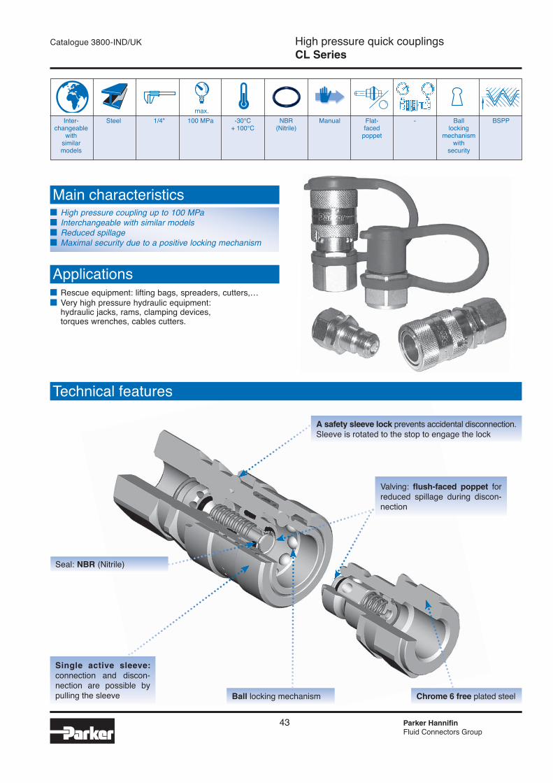
Main characteristics
Applications■ Rescue equipment: lifting bags, spreaders, cutters,…■ Very high pressure hydraulic equipment: hydraulic jacks, rams, clamping devices, torques wrenches, cables cutters.
Technical features
A safety sleeve lock prevents accidental disconnection. Sleeve is rotated to the stop to engage the lock
Seal: NBR (Nitrile)
Valving: fl ush-faced poppet for reduced spillage during discon-nection
Single active sleeve: connection and discon-nection are possible by pulling the sleeve Chrome 6 free plated steelBall locking mechanism
■ High pressure coupling up to 100 MPa■ Interchangeable with similar models■ Reduced spillage■ Maximal security due to a positive locking mechanism
Inter- Steel 1/4" 100 MPa -30°C NBR Manual Flat- - Ball BSPP changeable + 100°C (Nitrile) faced locking with poppet mechanism similar with models security
Catalogue 3800-IND/UK High pressure quick couplings CL Series
44 Parker Hannifi n Fluid Connectors Group
0 2 4 6 8 10 12
Flow rate in (l/mn)
0.14
0.12
0.10
0.08
0.06
0.04
0.02
0
Pre
ssur
e d
rop
(MP
a)
1/4"
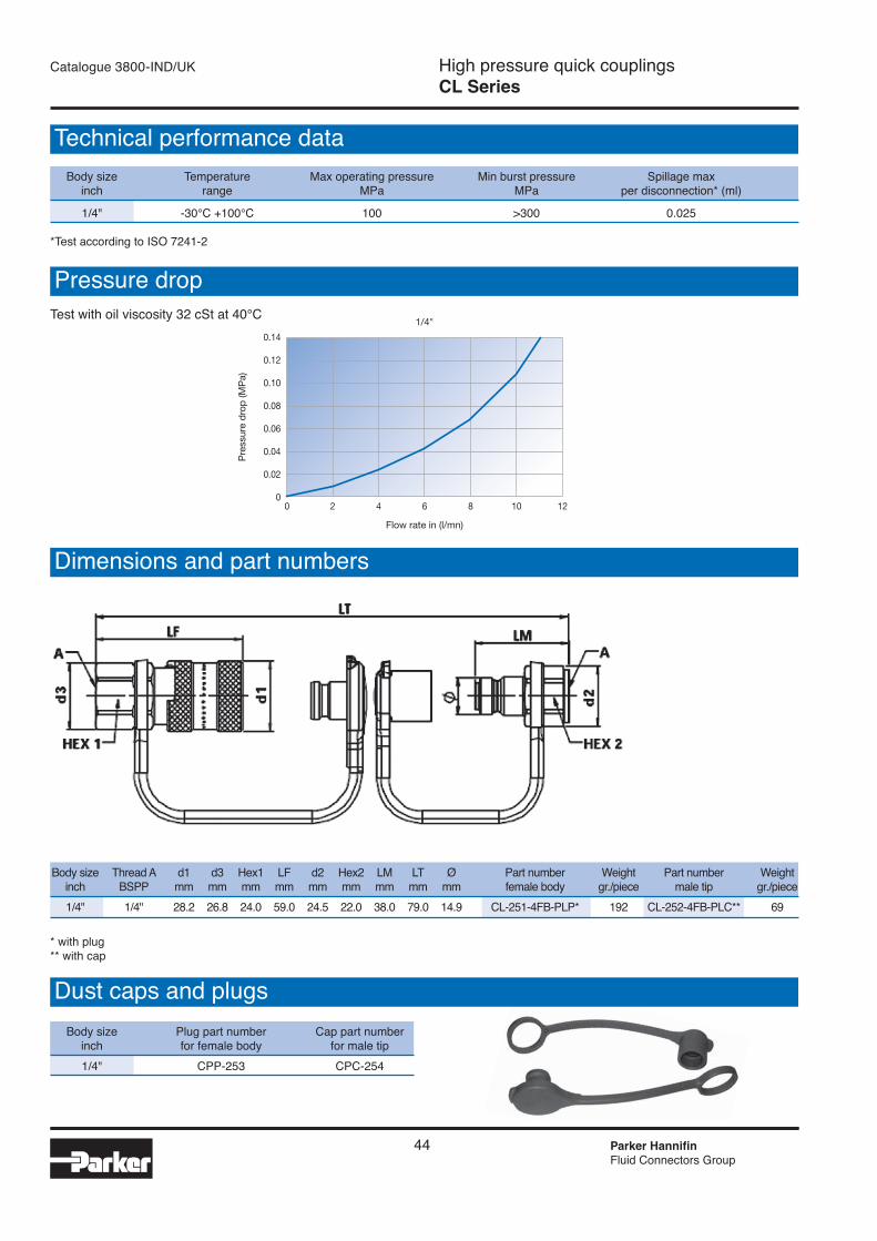
Technical performance data
Body size Temperature Max operating pressure Min burst pressure Spillage max inch range MPa MPa per disconnection* (ml)
1/4" -30°C +100°C 100 >300 0.025 *Test according to ISO 7241-2
Pressure drop
Dimensions and part numbers
Dust caps and plugs
Test with oil viscosity 32 cSt at 40°C
Body size Plug part number Cap part number inch for female body for male tip
1/4" CPP-253 CPC-254
Body size Thread A d1 d3 Hex1 LF d2 Hex2 LM LT Ø Part number Weight Part number Weight inch BSPP mm mm mm mm mm mm mm mm mm female body gr./piece male tip gr./piece
1/4" 1/4" 28.2 26.8 24.0 59.0 24.5 22.0 38.0 79.0 14.9 CL-251-4FB-PLP* 192 CL-252-4FB-PLC** 69
* with plug** with cap
Catalogue 3800-IND/UK High pressure quick couplings 3000 Series
45 Parker Hannifi n Fluid Connectors Group
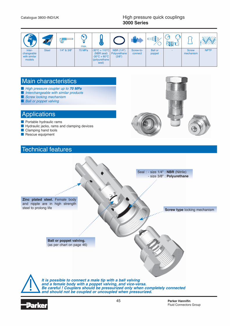
Main characteristics
Applications■ Portable hydraulic rams■ Hydraulic jacks, rams and clamping devices■ Clamping hand tools■ Rescue equipment
Technical features
It is possible to connect a male tip with a ball valving and a female body with a poppet valving, and vice-versa.Be careful ! Couplers should be pressurized only when completely connected and should not be coupled or uncoupled when pressurized.
Inter- Steel 1/4" & 3/8" 70 MPa -30°C + 110°C NBR (1/4") Screw-to- Ball or - Screw NPTF changeable (NBR seal) Polyurethane connect poppet mechanism with similar -30°C + 80°C (3/8") models (polyurethane seal)
■ High pressure coupler up to 70 MPa■ Interchangeable with similar products■ Screw locking mechanism■ Ball or poppet valving
Zinc plated steel. Female body and nipple are in high strength steel to prolong life
Ball or poppet valving.(as per chart on page 46)
Seal : - size 1/4" : NBR (Nitrile) - size 3/8" : Polyurethane
Screw type locking mechanism
Catalogue 3800-IND/UK High pressure quick couplings 3000 Series
46 Parker Hannifi n Fluid Connectors Group
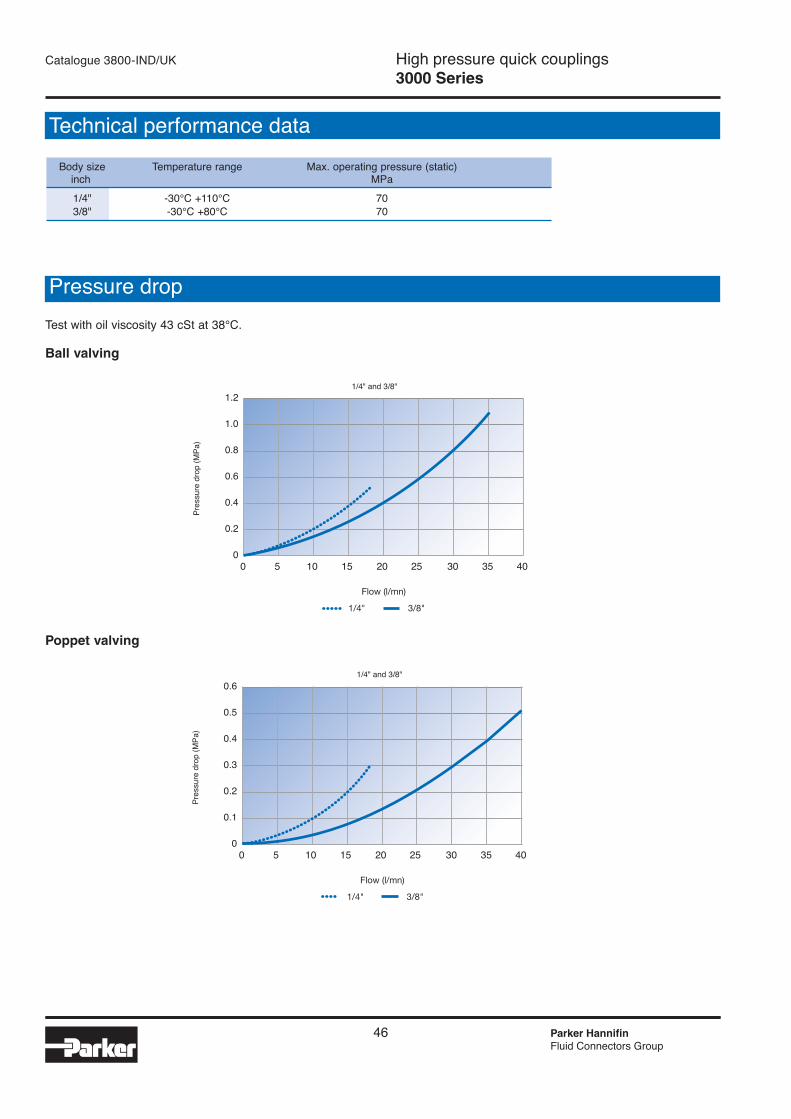
Technical performance data
Body size Temperature range Max. operating pressure (static) inch MPa
1/4" -30°C +110°C 70 3/8" -30°C +80°C 70
Pressure drop
Test with oil viscosity 43 cSt at 38°C.
Ball valving
Poppet valving
1/4" and 3/8"
Pre
ssur
e dr
op (
MP
a)
Flow (l/mn)
1/4" 3/8"
1/4" and 3/8"
Pre
ssur
e dr
op (
MP
a)
Catalogue 3800-IND/UK High pressure quick couplings 3000 Series
47 Parker Hannifi n Fluid Connectors Group
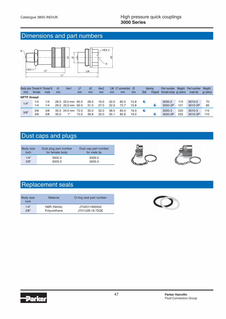
Dimensions and part numbers
Body size Dust plug part number Dust cap part number inch for female body for male tip
1/4" 3005-2 3009-2 3/8" 3005-3 3009-3
Dust caps and plugs
Replacement seals
Body size Material O-ring seal part number inch
1/4" NBR (Nitrile) JT020114N0552 3/8" Polyurethane JT01U28-18.72QE
Body size Thread A Thread B d1 Hex1 LF d2 Hex2 LM LT connected Ø Valving Part number Weight Part number Weight inch female male mm mm mm mm mm mm mm Ball Poppet female body gr./piece male tip gr./piece
NPTF thread
1/4" 1/4 1/4 28.5 22.0 mm 60.5 28.0 19.0 32.0 80.0 15.8 3050-2 115 3010-2 70
1/4 1/4 29.0 22.0 mm 60.5 31.0 27.0 32.0 73.7 15.8 3050-2P 121 3010-2P 85
3/8"
3/8 3/8 35.0 24.0 mm 72.0 35.0 32.0 38.0 85.0 19.0 3050-3 220 3010-3 115 3/8 3/8 35.0 1" 73.0 36.8 32.0 35.1 82.8 19.0 3050-3P 225 3010-3P 110
Catalogue 3800-IND/UK High pressure quick couplings FH Series
48 Parker Hannifi n Fluid Connectors Group
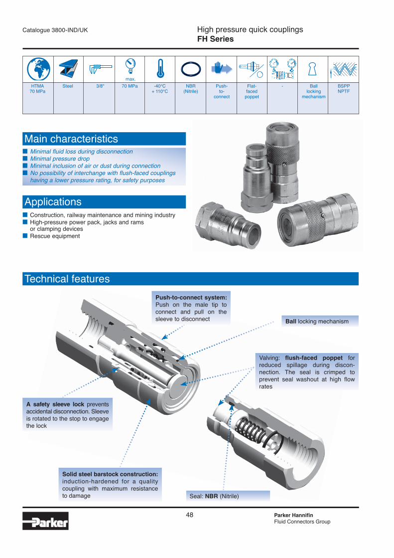
Main characteristics
Applications■ Construction, railway maintenance and mining industry■ High-pressure power pack, jacks and rams or clamping devices■ Rescue equipment
Technical features
A safety sleeve lock prevents accidental disconnection. Sleeve is rotated to the stop to engage the lock
Solid steel barstock construction: induction-hardened for a quality coupling with maximum resistance to damage
Valving: fl ush-faced poppet for reduced spillage during discon-nection. The seal is crimped to prevent seal washout at high fl ow rates
Seal: NBR (Nitrile)
Push-to-connect system: Push on the male tip to connect and pull on the sleeve to disconnect Ball locking mechanism
■ Minimal fl uid loss during disconnection■ Minimal pressure drop■ Minimal inclusion of air or dust during connection■ No possibility of interchange with fl ush-faced couplings having a lower pressure rating, for safety purposes
HTMA Steel 3/8" 70 MPa -40°C NBR Push- Flat- - Ball BSPP 70 MPa + 110°C (Nitrile) to- faced locking NPTF connect poppet mechanism
Catalogue 3800-IND/UK High pressure quick couplings FH Series
49 Parker Hannifi n Fluid Connectors Group
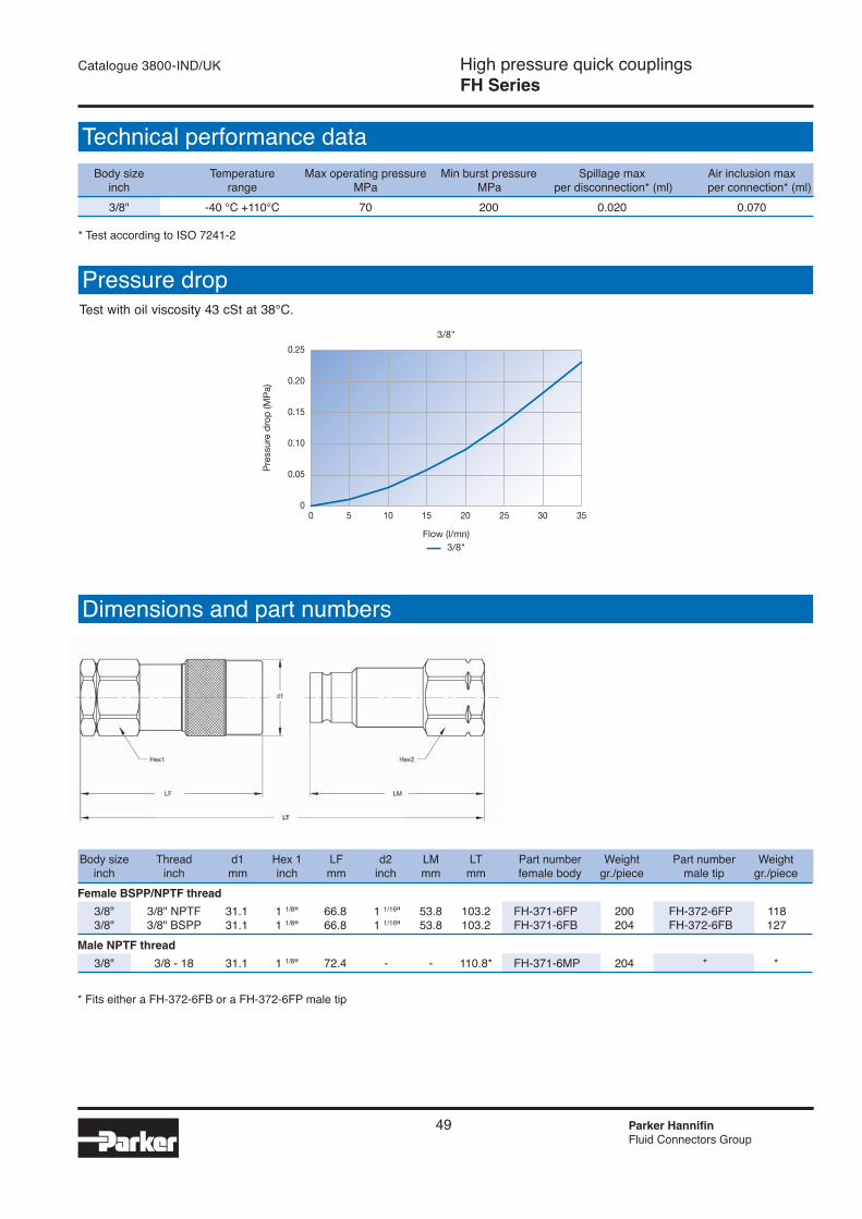
Body size Temperature Max operating pressure Min burst pressure Spillage max Air inclusion max inch range MPa MPa per disconnection* (ml) per connection* (ml)
3/8" -40 °C +110°C 70 200 0.020 0.070
* Test according to ISO 7241-2
Technical performance data
Pressure dropTest with oil viscosity 43 cSt at 38°C.
Dimensions and part numbers
0 5 10 15 20 25 30 35
Flow (l/mn)
0.25
0.20
0.15
0.10
0.05
0
Pre
ssur
e d
rop
(MP
a)
3/8"
3/8"
Body size Thread d1 Hex 1 LF d2 LM LT Part number Weight Part number Weight inch inch mm inch mm inch mm mm female body gr./piece male tip gr./piece
Female BSPP/NPTF thread
3/8" 3/8" NPTF 31.1 1 1/8" 66.8 1 1/16" 53.8 103.2 FH-371-6FP 200 FH-372-6FP 118 3/8" 3/8" BSPP 31.1 1 1/8" 66.8 1 1/16" 53.8 103.2 FH-371-6FB 204 FH-372-6FB 127
Male NPTF thread
3/8" 3/8 - 18 31.1 1 1/8" 72.4 - - 110.8* FH-371-6MP 204 * *
* Fits either a FH-372-6FB or a FH-372-6FP male tip
Catalogue 3800-IND/UK
50 Parker Hannifi n Fluid Connectors Group
Notes

Catalogue 3800-IND/UK Appendices Index
51 Parker Hannifi n Fluid Connectors Group
APPENDICESFLUID COMPTABILITY CHART .................................................................................................................................................Page 52
SAFETY GUIDE ...............................................................................................................................................................................................................Page 58
CONVERSION FACTORS ..........................................................................................................................................................................Page 60
ALPHA NUMERIC INDEX .......................................................................................................................................................................Page 63
PARKER HANNIFIN CORPORATION ............................................................................................................................Page 65
Catalogue 3800-IND/UK Appendices Fluid compatibility chart
52 Parker Hannifi n Fluid Connectors Group
Media Body material Seal material Brass Steel 316 S.S. 303 S.S. NBR (Nitrile) EPDM (EP) FKM (VitonTM) CR ( Neoprene)
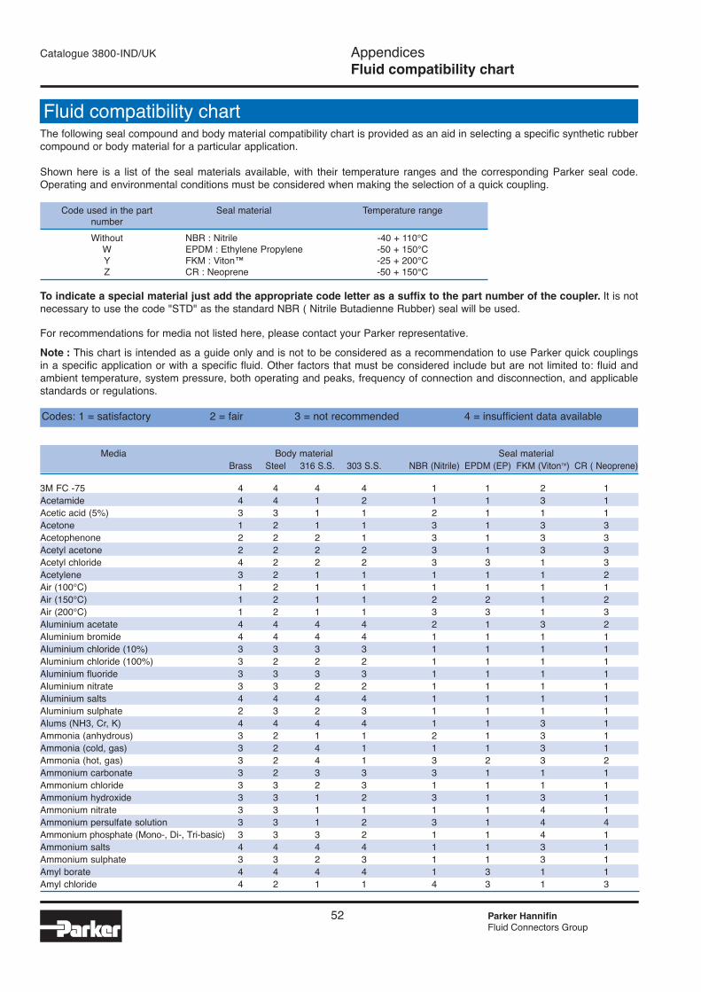
3M FC -75 4 4 4 4 1 1 2 1Acetamide 4 4 1 2 1 1 3 1Acetic acid (5%) 3 3 1 1 2 1 1 1Acetone 1 2 1 1 3 1 3 3Acetophenone 2 2 2 1 3 1 3 3Acetyl acetone 2 2 2 2 3 1 3 3Acetyl chloride 4 2 2 2 3 3 1 3Acetylene 3 2 1 1 1 1 1 2Air (100°C) 1 2 1 1 1 1 1 1Air (150°C) 1 2 1 1 2 2 1 2Air (200°C) 1 2 1 1 3 3 1 3Aluminium acetate 4 4 4 4 2 1 3 2Aluminium bromide 4 4 4 4 1 1 1 1Aluminium chloride (10%) 3 3 3 3 1 1 1 1Aluminium chloride (100%) 3 2 2 2 1 1 1 1Aluminium fl uoride 3 3 3 3 1 1 1 1Aluminium nitrate 3 3 2 2 1 1 1 1Aluminium salts 4 4 4 4 1 1 1 1Aluminium sulphate 2 3 2 3 1 1 1 1Alums (NH3, Cr, K) 4 4 4 4 1 1 3 1Ammonia (anhydrous) 3 2 1 1 2 1 3 1Ammonia (cold, gas) 3 2 4 1 1 1 3 1Ammonia (hot, gas) 3 2 4 1 3 2 3 2Ammonium carbonate 3 2 3 3 3 1 1 1Ammonium chloride 3 3 2 3 1 1 1 1Ammonium hydroxide 3 3 1 2 3 1 3 1Ammonium nitrate 3 3 1 1 1 1 4 1Ammonium persulfate solution 3 3 1 2 3 1 4 4Ammonium phosphate (Mono-, Di-, Tri-basic) 3 3 3 2 1 1 4 1Ammonium salts 4 4 4 4 1 1 3 1Ammonium sulphate 3 3 2 3 1 1 3 1Amyl borate 4 4 4 4 1 3 1 1Amyl chloride 4 2 1 1 4 3 1 3
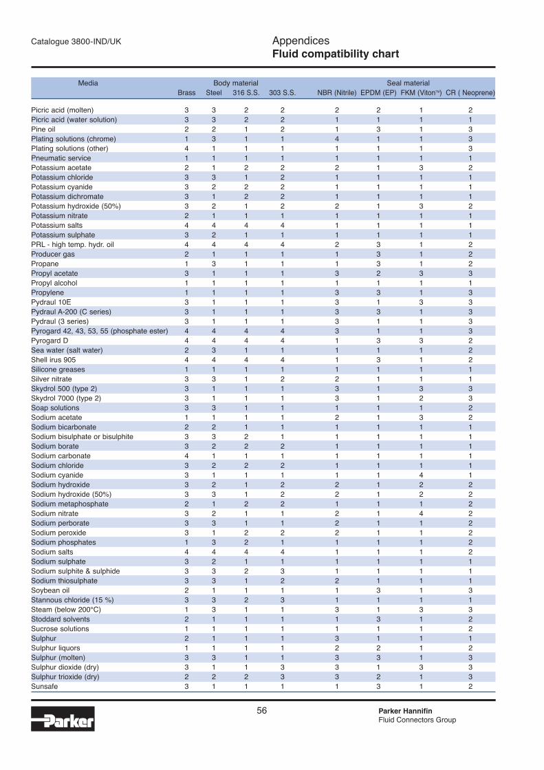
Fluid compatibility chartThe following seal compound and body material compatibility chart is provided as an aid in selecting a specifi c synthetic rubber compound or body material for a particular application.
Shown here is a list of the seal materials available, with their temperature ranges and the corresponding Parker seal code. Operating and environmental conditions must be considered when making the selection of a quick coupling.
For recommendations for media not listed here, please contact your Parker representative.
Note : This chart is intended as a guide only and is not to be considered as a recommendation to use Parker quick couplings in a specifi c application or with a specifi c fl uid. Other factors that must be considered include but are not limited to: fl uid and ambient temperature, system pressure, both operating and peaks, frequency of connection and disconnection, and applicable standards or regulations.
Codes: 1 = satisfactory 2 = fair 3 = not recommended 4 = insuffi cient data available
Code used in the part Seal material Temperature range number
Without NBR : Nitrile -40 + 110°C W EPDM : Ethylene Propylene -50 + 150°C Y FKM : Viton™ -25 + 200°C Z CR : Neoprene -50 + 150°C
To indicate a special material just add the appropriate code letter as a suffi x to the part number of the coupler. It is not necessary to use the code "STD" as the standard NBR ( Nitrile Butadienne Rubber) seal will be used.
Catalogue 3800-IND/UK Appendices Fluid compatibility chart
53 Parker Hannifi n Fluid Connectors Group
Media Body material Seal material Brass Steel 316 S.S. 303 S.S. NBR (Nitrile) EPDM (EP) FKM (VitonTM) CR ( Neoprene)
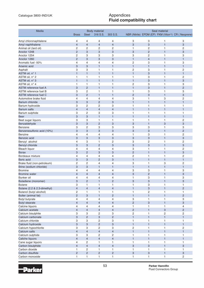
Amyl chloronaphtalene 4 4 4 4 3 3 1 3 Amyl naphthalene 4 4 4 4 3 3 1 3Animal oil (lard oil) 2 2 2 2 1 2 1 2Aroclor 1248 2 3 3 3 3 2 1 3Aroclor 1254 2 3 3 3 3 2 1 3Aroclor 1260 2 3 3 3 1 4 1 1Aromatic fuel -50% 4 4 4 4 2 3 1 3Arsenic acid 3 3 1 1 1 1 1 1Asphalt 3 3 1 1 2 3 1 2ASTM oil, n° 1 1 1 1 1 1 3 1 1ASTM oil, n° 2 1 1 1 1 1 3 1 2ASTM oil, n° 3 1 1 1 1 1 3 1 3ASTM oil, n° 4 1 1 1 1 2 3 1 3ASTM reference fuel A 3 2 1 1 1 3 1 2ASTM reference fuel B 3 2 1 1 1 3 1 3ASTM reference fuel C 3 2 1 1 2 3 1 3Automotive brake fl uid 4 4 4 4 3 1 3 2Barium chloride 3 3 2 3 1 1 1 1Barium hydroxide 3 2 2 3 1 1 1 1Barium salts 4 4 4 4 1 1 1 1Barium sulphide 3 2 3 3 1 1 1 1Beer 3 3 1 1 1 1 1 1Beet sugar liquors 3 3 1 1 1 1 1 2Benzaldehyde 3 3 2 3 3 1 3 3Benzene 3 2 3 3 3 3 1 3Benzenesulfonic acid (10%) 3 3 3 3 3 3 1 2Benzine 4 4 4 4 1 3 1 2Benzoic acid 3 3 3 3 3 3 1 3Benzyl alcohol 4 3 1 2 3 2 1 2Benzyl chloride 3 3 2 3 3 3 1 3Bleach liquor 4 4 4 4 3 1 1 2Borax 3 2 3 3 2 1 1 3Bordeaux mixture 4 4 4 4 2 1 1 2Boric acid 3 3 2 3 1 1 1 1Brake fl uid (non-petroleum) 2 2 4 4 3 1 3 2Brine (sodium chloride) 3 3 1 1 1 1 1 1Bromine 4 4 4 4 3 3 1 3Bromine water 4 4 4 4 3 2 1 3Bunker oil 4 4 4 4 1 3 1 3Butadiene (monomer) 3 2 1 2 3 3 1 3Butane 3 1 1 1 1 3 1 1Butane (2.2 & 2.3-dimethyl) 4 4 4 4 1 3 1 2Butanol (butyl alcohol) 2 1 1 1 1 2 1 1Butter (animal fat) 2 3 1 2 1 1 1 2Butyl butyrate 4 4 4 4 3 1 1 3Butyl stearate 4 4 4 4 2 3 1 3Calcine liquors 4 4 4 4 1 1 1 4Calcium acetate 4 4 4 4 2 1 3 2Calcium bisulphite 3 3 2 3 2 1 2 2Calcium carbonate 3 2 3 2 1 1 1 1Calcium chloride 3 3 2 3 1 1 1 1Calcium hydroxide 3 3 2 3 1 1 1 1Calcium hypochlorite 3 3 2 3 2 1 1 2Calcium salts 4 4 4 4 1 1 1 1Calcium sulphide 3 3 2 2 1 1 1 1Caliche liquors 4 4 4 4 1 1 1 1Cane sugar liquors 4 2 1 1 1 1 1 1Carbon bisulphide 4 4 4 4 3 3 1 3Carbon dioxide 1 2 1 1 1 1 1 1Carbon disulfi de 2 2 2 2 3 3 1 3Carbon monoxide 1 1 1 1 1 1 1 2
Catalogue 3800-IND/UK Appendices Fluid compatibility chart
54 Parker Hannifi n Fluid Connectors Group
Media Body material Seal material Brass Steel 316 S.S. 303 S.S. NBR (Nitrile) EPDM (EP) FKM (VitonTM) CR ( Neoprene)
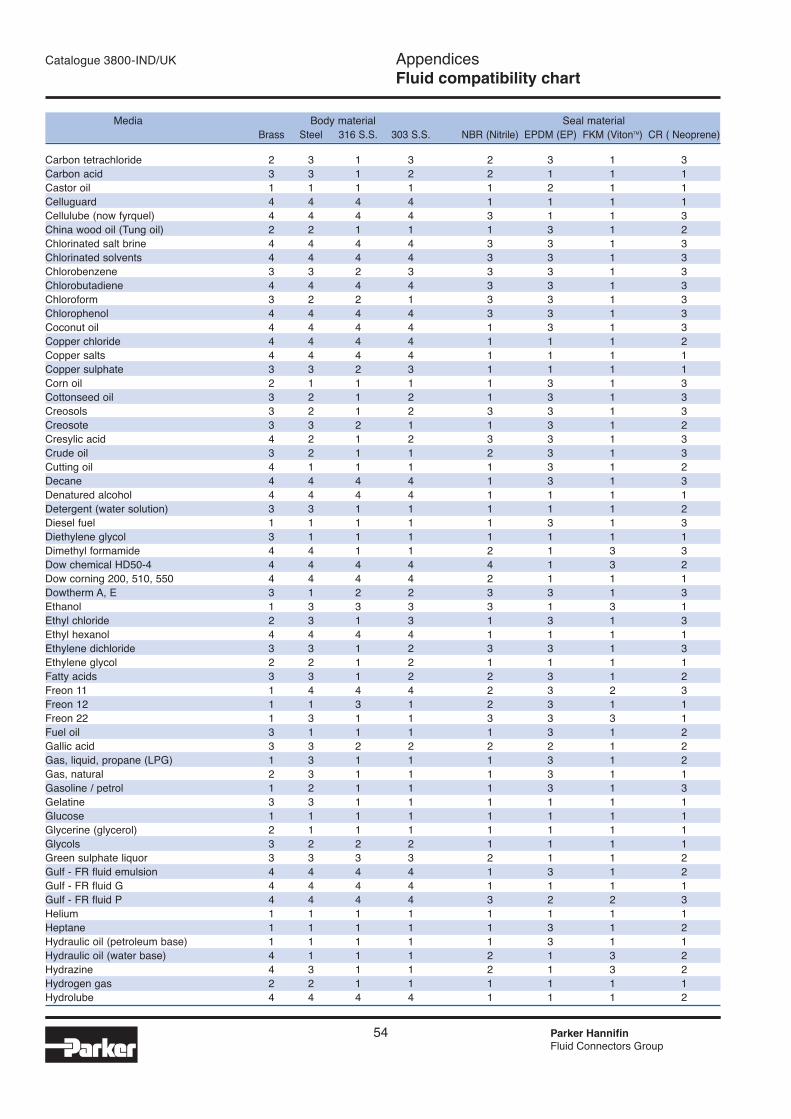
Carbon tetrachloride 2 3 1 3 2 3 1 3Carbon acid 3 3 1 2 2 1 1 1Castor oil 1 1 1 1 1 2 1 1Celluguard 4 4 4 4 1 1 1 1Cellulube (now fyrquel) 4 4 4 4 3 1 1 3China wood oil (Tung oil) 2 2 1 1 1 3 1 2Chlorinated salt brine 4 4 4 4 3 3 1 3Chlorinated solvents 4 4 4 4 3 3 1 3Chlorobenzene 3 3 2 3 3 3 1 3Chlorobutadiene 4 4 4 4 3 3 1 3Chloroform 3 2 2 1 3 3 1 3Chlorophenol 4 4 4 4 3 3 1 3Coconut oil 4 4 4 4 1 3 1 3Copper chloride 4 4 4 4 1 1 1 2Copper salts 4 4 4 4 1 1 1 1Copper sulphate 3 3 2 3 1 1 1 1Corn oil 2 1 1 1 1 3 1 3Cottonseed oil 3 2 1 2 1 3 1 3Creosols 3 2 1 2 3 3 1 3Creosote 3 3 2 1 1 3 1 2Cresylic acid 4 2 1 2 3 3 1 3Crude oil 3 2 1 1 2 3 1 3Cutting oil 4 1 1 1 1 3 1 2Decane 4 4 4 4 1 3 1 3Denatured alcohol 4 4 4 4 1 1 1 1Detergent (water solution) 3 3 1 1 1 1 1 2Diesel fuel 1 1 1 1 1 3 1 3Diethylene glycol 3 1 1 1 1 1 1 1Dimethyl formamide 4 4 1 1 2 1 3 3Dow chemical HD50-4 4 4 4 4 4 1 3 2Dow corning 200, 510, 550 4 4 4 4 2 1 1 1Dowtherm A, E 3 1 2 2 3 3 1 3Ethanol 1 3 3 3 3 1 3 1Ethyl chloride 2 3 1 3 1 3 1 3Ethyl hexanol 4 4 4 4 1 1 1 1Ethylene dichloride 3 3 1 2 3 3 1 3Ethylene glycol 2 2 1 2 1 1 1 1Fatty acids 3 3 1 2 2 3 1 2Freon 11 1 4 4 4 2 3 2 3Freon 12 1 1 3 1 2 3 1 1Freon 22 1 3 1 1 3 3 3 1Fuel oil 3 1 1 1 1 3 1 2Gallic acid 3 3 2 2 2 2 1 2Gas, liquid, propane (LPG) 1 3 1 1 1 3 1 2Gas, natural 2 3 1 1 1 3 1 1Gasoline / petrol 1 2 1 1 1 3 1 3Gelatine 3 3 1 1 1 1 1 1Glucose 1 1 1 1 1 1 1 1Glycerine (glycerol) 2 1 1 1 1 1 1 1Glycols 3 2 2 2 1 1 1 1Green sulphate liquor 3 3 3 3 2 1 1 2Gulf - FR fl uid emulsion 4 4 4 4 1 3 1 2Gulf - FR fl uid G 4 4 4 4 1 1 1 1Gulf - FR fl uid P 4 4 4 4 3 2 2 3Helium 1 1 1 1 1 1 1 1Heptane 1 1 1 1 1 3 1 2Hydraulic oil (petroleum base) 1 1 1 1 1 3 1 1Hydraulic oil (water base) 4 1 1 1 2 1 3 2Hydrazine 4 3 1 1 2 1 3 2Hydrogen gas 2 2 1 1 1 1 1 1Hydrolube 4 4 4 4 1 1 1 2
Catalogue 3800-IND/UK Appendices Fluid compatibility chart
55 Parker Hannifi n Fluid Connectors Group
Media Body material Seal material Brass Steel 316 S.S. 303 S.S. NBR (Nitrile) EPDM (EP) FKM (VitonTM) CR ( Neoprene)
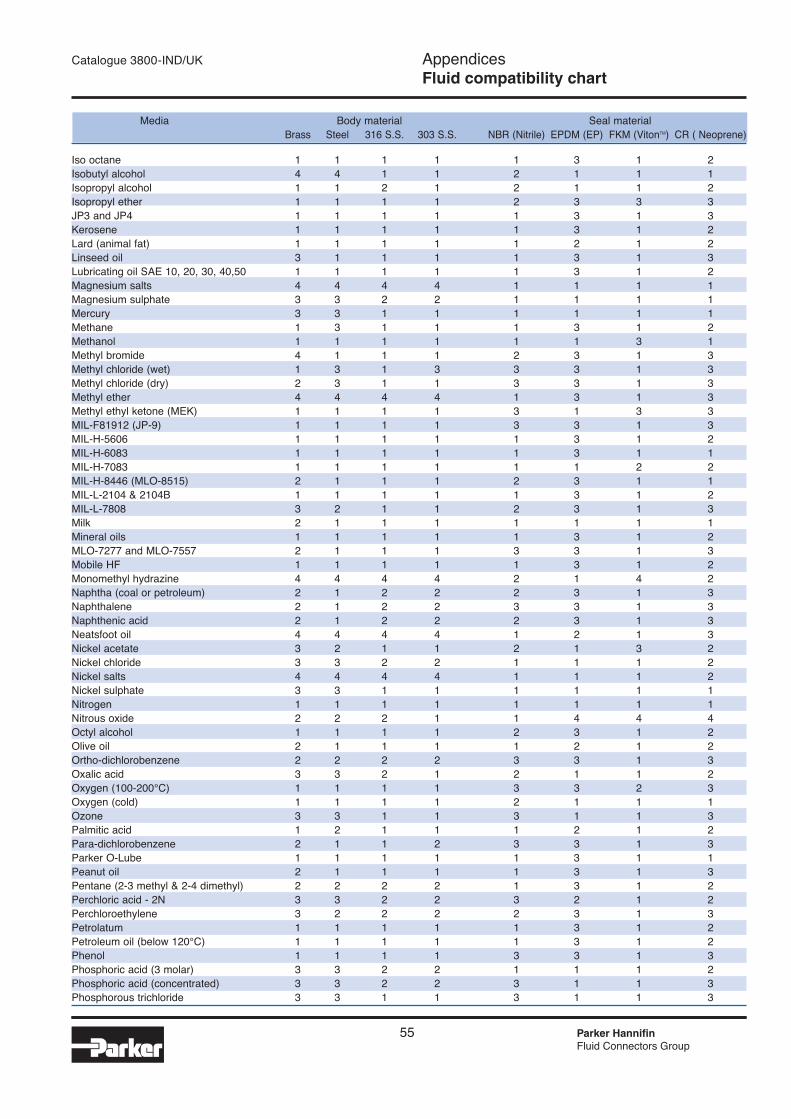
Iso octane 1 1 1 1 1 3 1 2 Isobutyl alcohol 4 4 1 1 2 1 1 1Isopropyl alcohol 1 1 2 1 2 1 1 2Isopropyl ether 1 1 1 1 2 3 3 3JP3 and JP4 1 1 1 1 1 3 1 3Kerosene 1 1 1 1 1 3 1 2Lard (animal fat) 1 1 1 1 1 2 1 2Linseed oil 3 1 1 1 1 3 1 3Lubricating oil SAE 10, 20, 30, 40,50 1 1 1 1 1 3 1 2Magnesium salts 4 4 4 4 1 1 1 1Magnesium sulphate 3 3 2 2 1 1 1 1Mercury 3 3 1 1 1 1 1 1Methane 1 3 1 1 1 3 1 2Methanol 1 1 1 1 1 1 3 1Methyl bromide 4 1 1 1 2 3 1 3Methyl chloride (wet) 1 3 1 3 3 3 1 3Methyl chloride (dry) 2 3 1 1 3 3 1 3Methyl ether 4 4 4 4 1 3 1 3Methyl ethyl ketone (MEK) 1 1 1 1 3 1 3 3MIL-F81912 (JP-9) 1 1 1 1 3 3 1 3MIL-H-5606 1 1 1 1 1 3 1 2MIL-H-6083 1 1 1 1 1 3 1 1MIL-H-7083 1 1 1 1 1 1 2 2MIL-H-8446 (MLO-8515) 2 1 1 1 2 3 1 1MIL-L-2104 & 2104B 1 1 1 1 1 3 1 2MIL-L-7808 3 2 1 1 2 3 1 3Milk 2 1 1 1 1 1 1 1Mineral oils 1 1 1 1 1 3 1 2MLO-7277 and MLO-7557 2 1 1 1 3 3 1 3Mobile HF 1 1 1 1 1 3 1 2Monomethyl hydrazine 4 4 4 4 2 1 4 2Naphtha (coal or petroleum) 2 1 2 2 2 3 1 3Naphthalene 2 1 2 2 3 3 1 3Naphthenic acid 2 1 2 2 2 3 1 3Neatsfoot oil 4 4 4 4 1 2 1 3Nickel acetate 3 2 1 1 2 1 3 2Nickel chloride 3 3 2 2 1 1 1 2Nickel salts 4 4 4 4 1 1 1 2Nickel sulphate 3 3 1 1 1 1 1 1Nitrogen 1 1 1 1 1 1 1 1Nitrous oxide 2 2 2 1 1 4 4 4Octyl alcohol 1 1 1 1 2 3 1 2Olive oil 2 1 1 1 1 2 1 2Ortho-dichlorobenzene 2 2 2 2 3 3 1 3Oxalic acid 3 3 2 1 2 1 1 2Oxygen (100-200°C) 1 1 1 1 3 3 2 3Oxygen (cold) 1 1 1 1 2 1 1 1Ozone 3 3 1 1 3 1 1 3Palmitic acid 1 2 1 1 1 2 1 2Para-dichlorobenzene 2 1 1 2 3 3 1 3Parker O-Lube 1 1 1 1 1 3 1 1Peanut oil 2 1 1 1 1 3 1 3Pentane (2-3 methyl & 2-4 dimethyl) 2 2 2 2 1 3 1 2Perchloric acid - 2N 3 3 2 2 3 2 1 2Perchloroethylene 3 2 2 2 2 3 1 3Petrolatum 1 1 1 1 1 3 1 2Petroleum oil (below 120°C) 1 1 1 1 1 3 1 2Phenol 1 1 1 1 3 3 1 3Phosphoric acid (3 molar) 3 3 2 2 1 1 1 2Phosphoric acid (concentrated) 3 3 2 2 3 1 1 3Phosphorous trichloride 3 3 1 1 3 1 1 3
Catalogue 3800-IND/UK Appendices Fluid compatibility chart
56 Parker Hannifi n Fluid Connectors Group
Media Body material Seal material Brass Steel 316 S.S. 303 S.S. NBR (Nitrile) EPDM (EP) FKM (VitonTM) CR ( Neoprene)
Picric acid (molten) 3 3 2 2 2 2 1 2Picric acid (water solution) 3 3 2 2 1 1 1 1Pine oil 2 2 1 2 1 3 1 3Plating solutions (chrome) 1 3 1 1 4 1 1 3Plating solutions (other) 4 1 1 1 1 1 1 3Pneumatic service 1 1 1 1 1 1 1 1Potassium acetate 2 1 2 2 2 1 3 2Potassium chloride 3 3 1 2 1 1 1 1Potassium cyanide 3 2 2 2 1 1 1 1Potassium dichromate 3 1 2 2 1 1 1 1Potassium hydroxide (50%) 3 2 1 2 2 1 3 2Potassium nitrate 2 1 1 1 1 1 1 1Potassium salts 4 4 4 4 1 1 1 1Potassium sulphate 3 2 1 1 1 1 1 1PRL - high temp. hydr. oil 4 4 4 4 2 3 1 2Producer gas 2 1 1 1 1 3 1 2Propane 1 3 1 1 1 3 1 2Propyl acetate 3 1 1 1 3 2 3 3Propyl alcohol 1 1 1 1 1 1 1 1Propylene 1 1 1 1 3 3 1 3Pydraul 10E 3 1 1 1 3 1 3 3Pydraul A-200 (C series) 3 1 1 1 3 3 1 3Pydraul (3 series) 3 1 1 1 3 1 1 3Pyrogard 42, 43, 53, 55 (phosphate ester) 4 4 4 4 3 1 1 3Pyrogard D 4 4 4 4 1 3 3 2Sea water (salt water) 2 3 1 1 1 1 1 2Shell irus 905 4 4 4 4 1 3 1 2Silicone greases 1 1 1 1 1 1 1 1Silver nitrate 3 3 1 2 2 1 1 1Skydrol 500 (type 2) 3 1 1 1 3 1 3 3Skydrol 7000 (type 2) 3 1 1 1 3 1 2 3Soap solutions 3 3 1 1 1 1 1 2Sodium acetate 1 1 1 1 2 1 3 2Sodium bicarbonate 2 2 1 1 1 1 1 1Sodium bisulphate or bisulphite 3 3 2 1 1 1 1 1Sodium borate 3 2 2 2 1 1 1 1Sodium carbonate 4 1 1 1 1 1 1 1Sodium chloride 3 2 2 2 1 1 1 1Sodium cyanide 3 1 1 1 1 1 4 1Sodium hydroxide 3 2 1 2 2 1 2 2Sodium hydroxide (50%) 3 3 1 2 2 1 2 2Sodium metaphosphate 2 1 2 2 1 1 1 2Sodium nitrate 3 2 1 1 2 1 4 2Sodium perborate 3 3 1 1 2 1 1 2Sodium peroxide 3 1 2 2 2 1 1 2Sodium phosphates 1 3 2 1 1 1 1 2Sodium salts 4 4 4 4 1 1 1 2Sodium sulphate 3 2 1 1 1 1 1 1Sodium sulphite & sulphide 3 3 2 3 1 1 1 1Sodium thiosulphate 3 3 1 2 2 1 1 1Soybean oil 2 1 1 1 1 3 1 3Stannous chloride (15 %) 3 3 2 3 1 1 1 1Steam (below 200°C) 1 3 1 1 3 1 3 3Stoddard solvents 2 1 1 1 1 3 1 2Sucrose solutions 1 1 1 1 1 1 1 2Sulphur 2 1 1 1 3 1 1 1Sulphur liquors 1 1 1 1 2 2 1 2Sulphur (molten) 3 3 1 1 3 3 1 3Sulphur dioxide (dry) 3 1 1 3 3 1 3 3Sulphur trioxide (dry) 2 2 2 3 3 2 1 3Sunsafe 3 1 1 1 1 3 1 2
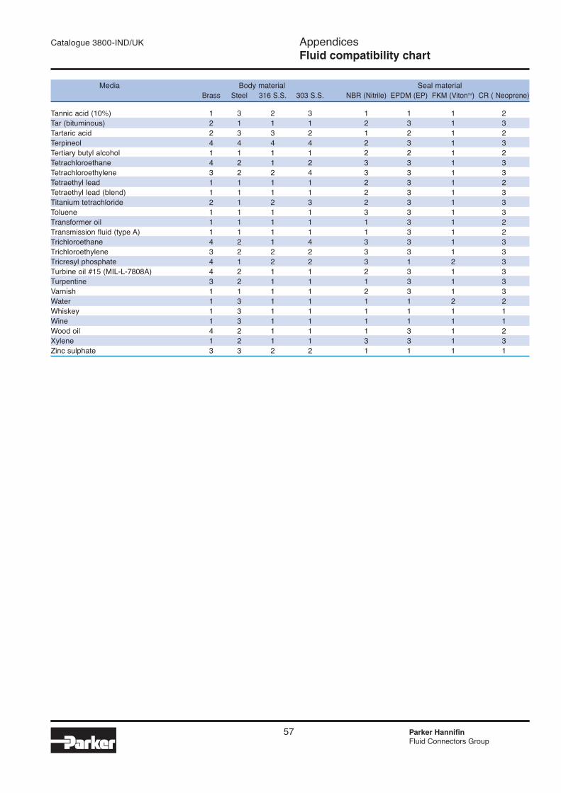
Catalogue 3800-IND/UK Appendices Fluid compatibility chart
57 Parker Hannifi n Fluid Connectors Group
Media Body material Seal material Brass Steel 316 S.S. 303 S.S. NBR (Nitrile) EPDM (EP) FKM (VitonTM) CR ( Neoprene)
Tannic acid (10%) 1 3 2 3 1 1 1 2Tar (bituminous) 2 1 1 1 2 3 1 3Tartaric acid 2 3 3 2 1 2 1 2Terpineol 4 4 4 4 2 3 1 3Tertiary butyl alcohol 1 1 1 1 2 2 1 2Tetrachloroethane 4 2 1 2 3 3 1 3Tetrachloroethylene 3 2 2 4 3 3 1 3Tetraethyl lead 1 1 1 1 2 3 1 2Tetraethyl lead (blend) 1 1 1 1 2 3 1 3Titanium tetrachloride 2 1 2 3 2 3 1 3Toluene 1 1 1 1 3 3 1 3Transformer oil 1 1 1 1 1 3 1 2Transmission fl uid (type A) 1 1 1 1 1 3 1 2Trichloroethane 4 2 1 4 3 3 1 3Trichloroethylene 3 2 2 2 3 3 1 3Tricresyl phosphate 4 1 2 2 3 1 2 3Turbine oil #15 (MIL-L-7808A) 4 2 1 1 2 3 1 3Turpentine 3 2 1 1 1 3 1 3Varnish 1 1 1 1 2 3 1 3Water 1 3 1 1 1 1 2 2Whiskey 1 3 1 1 1 1 1 1Wine 1 3 1 1 1 1 1 1Wood oil 4 2 1 1 1 3 1 2Xylene 1 2 1 1 3 3 1 3Zinc sulphate 3 3 2 2 1 1 1 1
Catalogue 3800-IND/UK Appendices Safety guide
58 Parker Hannifi n Fluid Connectors Group
SAFETY GUIDE FOR SELECTING AND USING QUICK ACTIONCOUPLINGS AND RELATED ACCESSORIES
DANGER: failure or improper selection or improper use of quick action couplings or related accessories can cause death, personal injury and property damage. Possible consequences of failure or improper selection or improper use of quick action couplings or related accessories include but are not limited to:
1.0 GENERAL INSTRUCTIONS
1.1 Scope: this safety guide provides instructions for selecting and using (including installing connecting, disconnecting, and maintaining) quick action couplings and related accessories (including caps, plugs, blow guns). This safety guide is a supplement to and is to be used with the specific Parker publications for the specific quick action couplings and related accessories that are being considered for use.
1.2 Fail-Safe: quick action couplings or the hose they are attached to can fail without warning for many reasons. Design all systems and equipment in a fail-safe mode, so that failure of the quick action coupling or hose will not endanger persons or property.
1.3 Distribution : provide a copy of this safety guide to each person who is responsible for selecting or using quick action coupling products. Do not select or use quick action couplings without thoroughly reading and understanding this safety guide as well as the specific Parker publications for the products considered or selected.
1.4 User responsibility: due to the wide variety of operating conditions and uses for quick action couplings, Parker and its distributors do not represent or warrant that any particular quick action coupling is suitable for any specific end use system. This safety guide does not analyse all technical parameters that must be considered in selecting a product. The user, through its own analysis and testing, is solely responsible for:• Making the final selection of the quick action couplings.• Assuring that the user’s requirements are met and that the use presents no health or safety hazards.• Providing all appropriate health and safety warnings on the equipment on which the quick action couplings are used.
1.5 Additional questions: call the appropriate Parker customer service department if you have any questions or require any additional information. For the telephone numbers of the appropriate customer service department, see the Parker publication for the product being considered or used.
2.0 QUICK ACTION COUPLINGS SELECTION INSTRUCTIONS
2.1 Pressure: quick action couplings selection must be made so that the published rated pressure of the coupling is equal to or greater than the maximum system pressure. Pressure surges in the system higher than the rated pressure of the coupling will shorten the quick action coupling’s life. Do not confuse burst pressure or other pressure values with rated pressure and do not use burst pressure or other pressure values for this purpose.
2.2 Fluid compatibility: quick action couplings selection must assure compatibility of the body and seal materials with the fl uid media used. See the fl uid compatibility chart.
2.2 Temperature: be certain that fl uid and ambient temperatures, both steady and transient, do not exceed the limitations of the quick action couplings. Use caution and hand protection when connecting or disconnecting quick action couplings that are heated or cooled by the media they are conducting or by their environment.
2.4 Size: transmission or power by means of pressurised liquid varies with pressure and rate of flow. The size of the quick action couplings and other components of the system must be adequate to keep pressure losses to a minimum and avoid damage due to heat generation or excessive fluid velocity.
2.5 Pressurised connection or disconnection: if connecting or disconnecting under pressure is a requirement, use only quick action couplings designed for that purpose. The rated operating pressure of a quick action coupling may not be the pressure at which it may be safely connected or disconnected.
2.6 Environment: care must be taken to ensure that quick action couplings are either compatible with or protected from the environment (that is, surrounding conditions) to which they are exposed. Environmental conditions including but not limited to ultraviolet radiation, ozone, moisture, water, salt water, chemicals, and air pollutants can cause degradation and premature failure.
• Couplings or parts thrown off at high speed • High velocity fl uid discharge • Contact with suddenly moving or falling objects that are to be held in position or moved by the conveyed fl uid • Dangerously whipping hose
Before selecting or using any Parker quick action couplings or related accessories, it is important that you read and follow the following instructions.
• Explosion or burning of the conveyed fl uid • Contact with conveyed fl uids that may be hot, cold, toxic, or otherwise injurious • Sparking or explosion while paint or fl ammable liquid spraying
Catalogue 3800-IND/UK Appendices Safety guide
59 Parker Hannifi n Fluid Connectors Group
2.7 Locking means: ball locking quick action couplings can unintentionally disconnect if they are dragged over obstructions on the end of a hose or if the sleeve is bumped or moved enough to cause disconnection. Sleeves designed with flanges to provide better gripping for oily or gloved hands are especially susceptible to accidental disconnection and should not be used where these conditions exist. Sleeve lock or union (threaded) sleeve designs should be considered where there is a potential for accidental uncoupling.
2.8 Mechanical loads: external forces can significantly reduce quick action couplings’ life or cause failure. Mechanical loads which must be considered include excessive tensile or side loads, and vibration. Unusual applications may require special testing prior to quick action couplings selection.
2.9 Specifications and standards: when selecting quick action couplings, government, industry, and Parker specifications must be reviewed and followed as applicable.
2.10 Vacuum: not all quick action couplings are suitable or recommended for vacuum service. Quick action couplings used for vacuum applications must be selected to ensure that the quick action couplings will withstand the vacuum and pressure of the system.
2.11 Fire resistant fluids: some fire resistant fluids require seals other than the standard NBR (nitrile) used in many quick action couplings.
2.12 Radiant heat: quick action couplings can be heated to destruction or loss of sealing without contact by such nearby items as hot manifolds or molten metal. The same heat source may then initiate a fi re. This can occur despite the presence of cool air around the quick action couplings.
2.13 Welding and brazing: heating of plated parts, including quick action couplings and port adapters, above 450 °F (232°C) such as during welding, brazing, or soldering may emit deadly gases and may cause coupling seal damage.
3.0 QUICK ACTION COUPLINGS INSTALLATION INSTRUCTIONS
3.1 Pre-installation inspection: before installing a quick action coupling, visually inspect it and check for correct style, body material, seal material, and catalogue number. Before fi nal installation, coupling halves should be connected and disconnected with a sample of the mating half with which they will be used.
3.2 Quick action coupling halves from other manufacturers: if a quick action coupling assembly is made up of one Parker half and one half from another manufacturer, the lowest pressure rating of the two halves should not be exceeded.
3.3 Fitting installation: use a thread sealant, when assembling taper pipe thread joints in quick action couplings. Be sure the sealant is compatible with the system fl uid or gas. To avoid system contamination, use a liquid or paste type sealant rather than a tape style. Use the fl ats provided to hold the quick action coupling when installing fi ttings. Do not use pipe wrenches or a vice on other parts of the coupling to hold it when installing or a removing fi ttings as damage or loosening of threaded joints in the coupling assembly could result. Do not apply excessive torque to taper pipe threads because cracking or splitting of the female component can result.
3.4 Caps and plugs: use dust caps and plugs when quick action couplings are not coupled to exclude dirt and contamination and to protect critical surfaces from damage.
3.5 Coupling location: locate quick action couplings where they can be reached for connection or disconnection without exposing the operator to slipping, falling, getting sprayed, or coming in contact with hot or moving parts.
3.6 Hose whips: use a hose whip (a short length of hose between the tool and the coupling half) instead of rigidly mounting a coupling half on hand tools or other devices. This reduces the potential for coupling damage if the tool is dropped and provides some isolation from mechanical vibration which could cause uncoupling.
4.0 QUICK ACTION COUPLINGS MAINTENANCE INSTRUCTIONS
4.1 Even with proper selection and installation, quick action coupling life may be signifi cantly reduced without a continuing maintenance program. Frequency should be determined by the severity of the application and risk potential. A maintenance program must be established and followed by the user and must include the following as a minimum:
4.2 Visual inspection of quick action couplings: any of the following conditions require immediate shut down and replacement of the quick action coupling:• Cracked, damaged, or corroded quick action couplings parts.• Leaks at the fi tting, valve or mating seal.• Broken coupling mounting hardware, especially breakaway clamps.
4.3 Visual inspection all other:• Leaking seals or port connections.• Excess dirt build-up on the coupling locking means or on the interface area of either coupling half.• Defective clamps, guards, and shields.• System fl uid level, fl uid type and any entrapment.
4.4 Functional test: operate the system at maximum operating pressure and check for possible malfunctions and freedom from leaks. Personnel must avoid potential hazardous areas while testing and using the system.
4.5 Replacement intervals: specifi c replacement intervals must be considered based on previous service life, government or industry recommendations, or when failures could result in unacceptable downtime, damage or injury risk. See instruction 1.2 above.
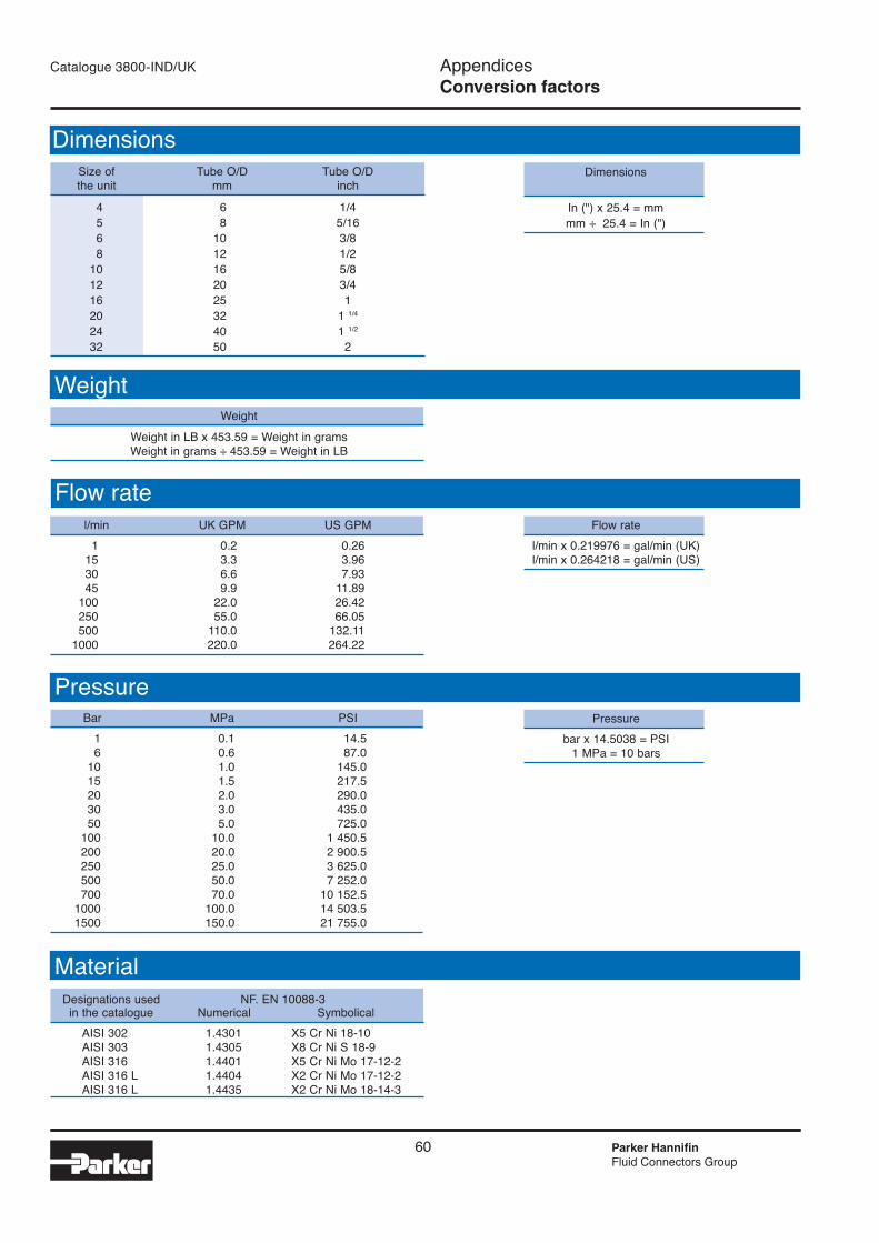
Catalogue 3800-IND/UK Appendices Conversion factors
60 Parker Hannifi n Fluid Connectors Group
Dimensions Size of Tube O/D Tube O/D the unit mm inch
4 6 1/4 5 8 5/16 6 10 3/8 8 12 1/2 10 16 5/8 12 20 3/4 16 25 1 20 32 1 1/4 24 40 1 1/2 32 50 2
Weight
Weight in LB x 453.59 = Weight in grams Weight in grams ÷ 453.59 = Weight in LB
Weight
Flow rate l/min UK GPM US GPM
1 0.2 0.26 15 3.3 3.96 30 6.6 7.93 45 9.9 11.89 100 22.0 26.42 250 55.0 66.05 500 110.0 132.11 1000 220.0 264.22
Flow rate
l/min x 0.219976 = gal/min (UK) l/min x 0.264218 = gal/min (US)
Pressure Pressure
bar x 14.5038 = PSI 1 MPa = 10 bars
Bar MPa PSI
1 0.1 14.5 6 0.6 87.0 10 1.0 145.0 15 1.5 217.5 20 2.0 290.0 30 3.0 435.0 50 5.0 725.0 100 10.0 1 450.5 200 20.0 2 900.5 250 25.0 3 625.0 500 50.0 7 252.0 700 70.0 10 152.5 1000 100.0 14 503.5 1500 150.0 21 755.0
Material Designations used NF. EN 10088-3 in the catalogue Numerical Symbolical
AISI 302 1.4301 X5 Cr Ni 18-10 AISI 303 1.4305 X8 Cr Ni S 18-9 AISI 316 1.4401 X5 Cr Ni Mo 17-12-2 AISI 316 L 1.4404 X2 Cr Ni Mo 17-12-2 AISI 316 L 1.4435 X2 Cr Ni Mo 18-14-3
Dimensions
In (") x 25.4 = mm mm ÷ 25.4 = In (")
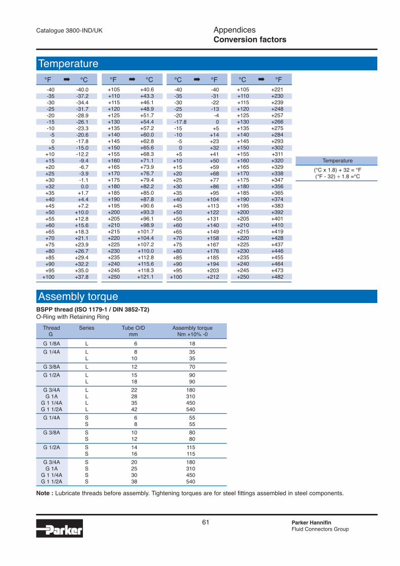
Catalogue 3800-IND/UK Appendices Conversion factors
61 Parker Hannifi n Fluid Connectors Group
Assembly torque
Thread Series Tube O/D Assembly torque G mm Nm +10% -0
G 1/8A L 6 18
G 1/4A L 8 35 L 10 35
G 3/8A L 12 70
G 1/2A L 15 90 L 18 90
G 3/4A L 22 180 G 1A L 28 310 G 1 1/4A L 35 450 G 1 1/2A L 42 540
G 1/4A S 6 55 S 8 55
G 3/8A S 10 80 S 12 80
G 1/2A S 14 115 S 16 115
G 3/4A S 20 180 G 1A S 25 310 G 1 1/4A S 30 450 G 1 1/2A S 38 540
Note : Lubricate threads before assembly. Tightening torques are for steel fi ttings assembled in steel components.
BSPP thread (ISO 1179-1 / DIN 3852-T2) O-Ring with Retaining Ring
Temperature °F ➡ °C -40 -40.0 -35 -37.2 -30 -34.4 -25 -31.7 -20 -28.9 -15 -26.1 -10 -23.3 -5 -20.6 0 -17.8 +5 -15.0 +10 -12.2 +15 -9.4 +20 -6.7 +25 -3.9 +30 -1.1 +32 0.0 +35 +1.7 +40 +4.4 +45 +7.2 +50 +10.0 +55 +12.8 +60 +15.6 +65 +18.3 +70 +21.1 +75 +23.9 +80 +26.7 +85 +29.4 +90 +32.2 +95 +35.0 +100 +37.8
°C ➡ °F -40.0 -40 -35.0 -31 -30.0 -22 -25.0 -13 -20.0 -4 -17.8 0 -15.0 +5 -10.0 +14 -5.0 +23 0.0 +32 +5.0 +41 +10.0 +50 +15.0 +59 +20.0 +68 +25.0 +77 +30.0 +86 +35.0 +95 +40.0 +104 +45.0 +113 +50.0 +122 +55.0 +131 +60.0 +140 +65.0 +149 +70.0 +158 +75.0 +167 +80.0 +176 +85.0 +185 +90.0 +194 +95.0 +203 +100.0 +212
Temperature
(°C x 1.8) + 32 = °F (°F - 32) ÷ 1.8 =°C
°F ➡ °C +105 +40.6 +110 +43.3 +115 +46.1 +120 +48.9 +125 +51.7 +130 +54.4 +135 +57.2 +140 +60.0 +145 +62.8 +150 +65.6 +155 +68.3 +160 +71.1 +165 +73.9 +170 +76.7 +175 +79.4 +180 +82.2 +185 +85.0 +190 +87.8 +195 +90.6 +200 +93.3 +205 +96.1 +210 +98.9 +215 +101.7 +220 +104.4 +225 +107.2 +230 +110.0 +235 +112.8 +240 +115.6 +245 +118.3 +250 +121.1
°C ➡ °F +105 +221 +110 +230 +115 +239 +120 +248 +125 +257 +130 +266 +135 +275 +140 +284 +145 +293 +150 +302 +155 +311 +160 +320 +165 +329 +170 +338 +175 +347 +180 +356 +185 +365 +190 +374 +195 +383 +200 +392 +205 +401 +210 +410 +215 +419 +220 +428 +225 +437 +230 +446 +235 +455 +240 +464 +245 +473 +250 +482
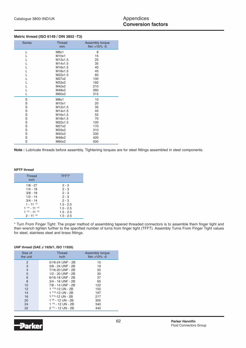
Catalogue 3800-IND/UK Appendices Conversion factors
62 Parker Hannifi n Fluid Connectors Group
Series Thread Assembly torque mm Nm +10% -0
L M8x1 8 L M10x1 15 L M12x1.5 25 L M14x1.5 35 L M16x1.5 40 L M18x1.5 45 L M22x1.5 60 L M27x2 100 L M33x2 160 L M42x2 210 L M48x2 260 L M60x2 315
S M8x1 10 S M10x1 20 S M12x1.5 35 S M14x1.5 45 S M16x1.5 55 S M18x1.5 70 S M22x1.5 100 S M27x2 170 S M33x2 310 S M42x2 330 S M48x2 420 S M60x2 500
Metric thread (ISO 6149 / DIN 3852 -T3)
Note : Lubricate threads before assembly. Tightening torques are for steel fi ttings assembled in steel components.
* Turn From Finger Tight: The proper method of assembling tapered threaded connectors is to assemble them fi nger tight and then wrench tighten further to the specifi ed number of turns from fi nger tight (TFFT). Assembly Turns From Finger Tight values for steel, stainless steel and brass fi ttings.
Thread TFFT* inch
1/8 - 27 2 - 3 1/4 - 18 2 - 3 3/8 - 18 2 - 3 1/2 - 14 2 - 3 3/4 - 14 2 - 3 1 - 11 1/2 1.5 - 2.5 1 1/4 - 11 1/2 1.5 - 2.5 1 1/2 - 11 1/2 1.5 - 2.5 2 - 11 1/2 1.5 - 2.5
NPTF thread
UNF thread (SAE J 1926/1, ISO 11926)
Size of Thread Assembly torque the unit inch Nm +10% -0
2 5/16-24 UNF - 2B 10 3 3/8 - 24 UNF - 2B 19 4 7/16-20 UNF - 2B 25 5 1/2 - 20 UNF - 2B 30 6 9/16-18 UNF - 2B 37 8 3/4 - 16 UNF - 2B 65 10 7/8 - 14 UNF - 2B 122 12 1 1/16-12 UN - 2B 150 14 1 3/16-12 UN - 2B 197 16 1 5/16-12 UN - 2B 217 20 1 5/8 - 12 UN - 2B 305 24 1 7/8 - 12 UN - 2B 340 32 2 1/2 - 12 UN - 2B 440
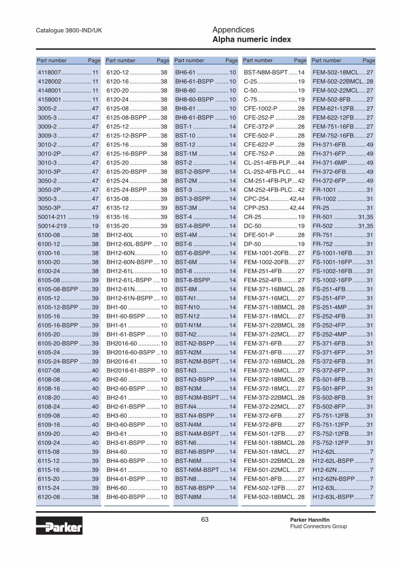
Catalogue 3800-IND/UK Appendices Alpha numeric index
63 Parker Hannifi n Fluid Connectors Group
Part number Page Part number Page Part number Page Part number Page Part number Page
4118007 .................. 11
4128002 ................. 11
4148001 ................. 11
4158001 ................. 11
3005-2 ....................47
3005-3 ....................47
3009-2 ....................47
3009-3 ....................47
3010-2 ....................47
3010-2P ..................47
3010-3 ....................47
3010-3P ..................47
3050-2 ....................47
3050-2P ..................47
3050-3 ....................47
3050-3P ..................47
50014-211 ..............19
50014-219 ..............19
6100-08 ..................38
6100-12 ..................38
6100-16 ..................38
6100-20 ..................38
6100-24 ..................38
6105-08 ..................39
6105-08-BSPP .......39
6105-12 ..................39
6105-12-BSPP .......39
6105-16 ..................39
6105-16-BSPP .......39
6105-20 ..................39
6105-20-BSPP .......39
6105-24 ..................39
6105-24-BSPP .......39
6107-08 ..................40
6108-08 ..................40
6108-16 ..................40
6108-20 ..................40
6108-24 ..................40
6109-08 ..................40
6109-16 ..................40
6109-20 ..................40
6109-24 ..................40
6115-08 ..................39
6115-12 ..................39
6115-16 ..................39
6115-20 ..................39
6115-24 ..................39
6120-08 ..................38
6120-12 ..................38
6120-16 ..................38
6120-20 ..................38
6120-24 ..................38
6125-08 ..................38
6125-08-BSPP .......38
6125-12 ..................38
6125-12-BSPP .......38
6125-16 ..................38
6125-16-BSPP .......38
6125-20 ..................38
6125-20-BSPP .......38
6125-24 ..................38
6125-24-BSPP .......38
6135-08 ..................39
6135-12 ..................39
6135-16 ..................39
6135-20 ..................39
BH12-60L ...............10
BH12-60L-BSPP ....10
BH12-60N ...............10
BH12-60N-BSPP ....10
BH12-61L ...............10
BH12-61L-BSPP ....10
BH12-61N ...............10
BH12-61N-BSPP ....10
BH1-60 ...................10
BH1-60-BSPP ........10
BH1-61 ...................10
BH1-61-BSPP ........10
BH2016-60 .............10
BH2016-60-BSPP ..10
BH2016-61 .............10
BH2016-61-BSPP ..10
BH2-60 ...................10
BH2-60-BSPP ........10
BH2-61 ...................10
BH2-61-BSPP ........10
BH3-60 ...................10
BH3-60-BSPP ........10
BH3-61 ...................10
BH3-61-BSPP ........10
BH4-60 ...................10
BH4-60-BSPP ........10
BH4-61 ...................10
BH4-61-BSPP ........10
BH6-60 ...................10
BH6-60-BSPP ........10
BH6-61 ...................10
BH6-61-BSPP ........10
BH8-60 ...................10
BH8-60-BSPP ........10
BH8-61 ...................10
BH8-61-BSPP ........10
BST-1 .....................14
BST-10 ...................14
BST-12 ...................14
BST-1M ..................14
BST-2 .....................14
BST-2-BSPP ...........14
BST-2M ..................14
BST-3 .....................14
BST-3-BSPP ...........14
BST-3M ..................14
BST-4 .....................14
BST-4-BSPP ...........14
BST-4M ..................14
BST-6 .....................14
BST-6-BSPP ...........14
BST-6M ..................14
BST-8 .....................14
BST-8-BSPP ...........14
BST-8M ..................14
BST-N1 ...................14
BST-N10 .................14
BST-N12 .................14
BST-N1M ................14
BST-N2 ...................14
BST-N2-BSPP ........14
BST-N2M ................14
BST-N2M-BSPT .....14
BST-N3 ...................14
BST-N3-BSPP ........14
BST-N3M ................14
BST-N3M-BSPT .....14
BST-N4 ...................14
BST-N4-BSPP ........14
BST-N4M ................14
BST-N4M-BSPT .....14
BST-N6 ...................14
BST-N6-BSPP ........14
BST-N6M ................14
BST-N6M-BSPT .....14
BST-N8 ...................14
BST-N8-BSPP ........14
BST-N8M ................14
BST-N8M-BSPT .....14
C-25 ........................19
C-50 ........................19
C-75 ........................19
CFE-1002-P ...........28
CFE-252-P .............28
CFE-372-P .............28
CFE-502-P .............28
CFE-622-P .............28
CFE-752-P .............28
CL-251-4FB-PLP ....44
CL-252-4FB-PLC ....44
CM-251-4FB-PLP ...42
CM-252-4FB-PLC ...42
CPC-254 ............42,44
CPP-253 ............42,44
CR-25 .....................19
DC-50 .....................19
DFE-501-P .............28
DP-50 .....................19
FEM-1001-20FB .....27
FEM-1002-20FB .....27
FEM-251-4FB .........27
FEM-252-4FB .........27
FEM-371-16BMCL..28
FEM-371-16MCL ....27
FEM-371-18BMCL..28
FEM-371-18MCL ....27
FEM-371-22BMCL..28
FEM-371-22MCL ....27
FEM-371-6FB .........27
FEM-371-8FB .........27
FEM-372-16BMCL..28
FEM-372-16MCL ....27
FEM-372-18BMCL..28
FEM-372-18MCL ....27
FEM-372-22BMCL..28
FEM-372-22MCL ....27
FEM-372-6FB .........27
FEM-372-8FB .........27
FEM-501-12FB .......27
FEM-501-18BMCL..28
FEM-501-18MCL ....27
FEM-501-22BMCL..28
FEM-501-22MCL ....27
FEM-501-8FB .........27
FEM-502-12FB .......27
FEM-502-18BMCL..28
FEM-502-18MCL ....27
FEM-502-22BMCL..28
FEM-502-22MCL ....27
FEM-502-8FB .........27
FEM-621-12FB .......27
FEM-622-12FB .......27
FEM-751-16FB .......27
FEM-752-16FB .......27
FH-371-6FB ............49
FH-371-6FP ............49
FH-371-6MP ...........49
FH-372-6FB ............49
FH-372-6FP ............49
FR-1001 .................31
FR-1002 .................31
FR-25 .....................31
FR-501 ..............31,35
FR-502 ..............31,35
FR-751 ...................31
FR-752 ...................31
FS-1001-16FB ........31
FS-1001-16FP ........31
FS-1002-16FB ........31
FS-1002-16FP ........31
FS-251-4FB ............31
FS-251-4FP ............31
FS-251-4MP ...........31
FS-252-4FB ............31
FS-252-4FP ............31
FS-252-4MP ...........31
FS-371-6FB ............31
FS-371-6FP ............31
FS-372-6FB ............31
FS-372-6FP ............31
FS-501-8FB ............31
FS-501-8FP ............31
FS-502-8FB ............31
FS-502-8FP ............31
FS-751-12FB ..........31
FS-751-12FP ..........31
FS-752-12FB ..........31
FS-752-12FP ..........31
H12-62L ....................7
H12-62L-BSPP .........7
H12-62N ...................7
H12-62N-BSPP ........7
H12-63L ....................7
H12-63L-BSPP .........7
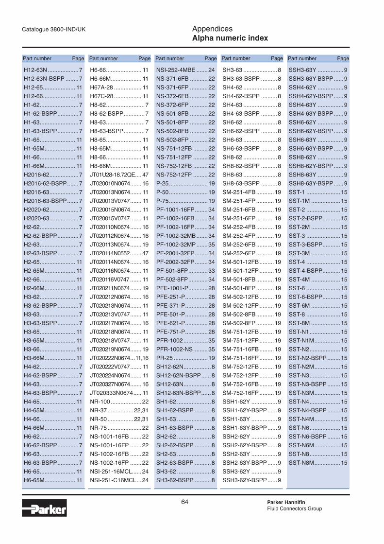
Catalogue 3800-IND/UK Appendices Alpha numeric index
64 Parker Hannifi n Fluid Connectors Group
Part number Page Part number Page Part number Page Part number Page Part number Page
H12-63N ...................7
H12-63N-BSPP ........7
H12-65 .................... 11
H12-66 .................... 11
H1-62 ........................7
H1-62-BSPP .............7
H1-63 ........................7
H1-63-BSPP .............7
H1-65 ...................... 11
H1-65M ................... 11
H1-66 ...................... 11
H1-66M ................... 11
H2016-62 ..................7
H2016-62-BSPP .......7
H2016-63 ..................7
H2016-63-BSPP .......7
H2020-62 ..................7
H2020-63 ..................7
H2-62 ........................7
H2-62-BSPP .............7
H2-63 ........................7
H2-63-BSPP .............7
H2-65 ...................... 11
H2-65M ................... 11
H2-66 ...................... 11
H2-66M ................... 11
H3-62 ........................7
H3-62-BSPP .............7
H3-63 ........................7
H3-63-BSPP .............7
H3-65 ...................... 11
H3-65M ................... 11
H3-66 ...................... 11
H3-66M ................... 11
H4-62 ........................7
H4-62-BSPP .............7
H4-63 ........................7
H4-63-BSPP .............7
H4-65 ...................... 11
H4-65M ................... 11
H4-66 ...................... 11
H4-66M ................... 11
H6-62 ........................7
H6-62-BSPP .............7
H6-63 ........................7
H6-63-BSPP .............7
H6-65 ...................... 11
H6-65M ................... 11
H6-66 ...................... 11
H6-66M ................... 11
H67A-28 ................. 11
H67C-28 ................. 11
H8-62 ........................7
H8-62-BSPP .............7
H8-63 ........................7
H8-63-BSPP .............7
H8-65 ...................... 11
H8-65M ................... 11
H8-66 ...................... 11
H8-66M ................... 11
JT01U28-18.72QE .... 47
JT020010N0674 ....... 16
JT020013N0674 ....... 11
JT020013V0747 ....... 11
JT020015N0674 ....... 11
JT020015V0747 ....... 11
JT020110N0674 ....... 16
JT020112N0674 ....... 16
JT020113N0674 ....... 19
JT020114N0552. ...... 47
JT020114N0674 ....... 16
JT020116N0674 ....... 11
JT020116V0747 ....... 11
JT020211N0674 ....... 19
JT020212N0674 ....... 16
JT020213N0674 ....... 11
JT020213V0747 ....... 11
JT020217N0674 ....... 16
JT020218N0674 ....... 11
JT020218V0747 ....... 11
JT020219N0674 ....... 19
JT020222N0674 ...11,16
JT020222V0747 ....... 11
JT020224N0674 ....... 11
JT020327N0674 ....... 16
JT020333N0674 ..... 11
NR-100 ...................22
NR-37 ................22,31
NR-50 ................22,31
NR-75 .....................22
NS-1001-16FB .......22
NS-1001-16FP .......22
NS-1002-16FB .......22
NS-1002-16FP .......22
NSI-251-16MCL......24
NSI-251-C16MCL ...24
NSI-252-4MBE .......24
NS-371-6FB ...........22
NS-371-6FP ...........22
NS-372-6FB ...........22
NS-372-6FP ...........22
NS-501-8FB ...........22
NS-501-8FP ...........22
NS-502-8FB ...........22
NS-502-8FP ...........22
NS-751-12FB .........22
NS-751-12FP .........22
NS-752-12FB .........22
NS-752-12FP .........22
P-25 ........................19
P-50 ........................19
P-75 ........................19
PF-1001-16FP ........34
PF-1002-16FB ........34
PF-1002-16FP ........34
PF-1002-32MB .......34
PF-1002-32MP .......35
PF-2001-32FP ........34
PF-2002-32FP ........34
PF-501-8FP ............33
PF-502-8FP ............34
PFE-1001-P ............28
PFE-251-P ..............28
PFE-371-P ..............28
PFE-501-P ..............28
PFE-621-P ..............28
PFE-751-P ..............28
PFR-1002 ...............35
PFR-1002-NS .........35
PR-25 .....................19
SH12-62N .................8
SH12-62N-BSPP ......8
SH12-63N .................8
SH12-63N-BSPP ......8
SH1-62 .....................8
SH1-62-BSPP ..........8
SH1-63 .....................8
SH1-63-BSPP ..........8
SH2-62 .....................8
SH2-62-BSPP ..........8
SH2-63 .....................8
SH2-63-BSPP ..........8
SH3-62 .....................8
SH3-62-BSPP ..........8
SH3-63 .....................8
SH3-63-BSPP ..........8
SH4-62 .....................8
SH4-62-BSPP ..........8
SH4-63 .....................8
SH4-63-BSPP ..........8
SH6-62 .....................8
SH6-62-BSPP ..........8
SH6-63 .....................8
SH6-63-BSPP ..........8
SH8-62 .....................8
SH8-62-BSPP ..........8
SH8-63 .....................8
SH8-63-BSPP ..........8
SM-251-4FB ...........19
SM-251-4FP ...........19
SM-251-6FB ...........19
SM-251-6FP ...........19
SM-252-4FB ...........19
SM-252-4FP ...........19
SM-252-6FB ...........19
SM-252-6FP ...........19
SM-501-12FB .........19
SM-501-12FP .........19
SM-501-8FB ...........19
SM-501-8FP ...........19
SM-502-12FB .........19
SM-502-12FP .........19
SM-502-8FB ...........19
SM-502-8FP ...........19
SM-751-12FB .........19
SM-751-12FP .........19
SM-751-16FB .........19
SM-751-16FP .........19
SM-752-12FB .........19
SM-752-12FP .........19
SM-752-16FB .........19
SM-752-16FP .........19
SSH1-62Y ................9
SSH1-62Y-BSPP ......9
SSH1-63Y ................9
SSH1-63Y-BSPP ......9
SSH2-62Y ................9
SSH2-62Y-BSPP ......9
SSH2-63Y ................9
SSH2-63Y-BSPP ......9
SSH3-62Y ................9
SSH3-62Y-BSPP ......9
SSH3-63Y ................9
SSH3-63Y-BSPP ......9
SSH4-62Y ................9
SSH4-62Y-BSPP ......9
SSH4-63Y ................9
SSH4-63Y-BSPP ......9
SSH6-62Y ................9
SSH6-62Y-BSPP ......9
SSH6-63Y ................9
SSH6-63Y-BSPP ......9
SSH8-62Y ................9
SSH8-62Y-BSPP ......9
SSH8-63Y ................9
SSH8-63Y-BSPP ......9
SST-1 .....................15
SST-1M ..................15
SST-2 .....................15
SST-2-BSPP ...........15
SST-2M ..................15
SST-3 .....................15
SST-3-BSPP ...........15
SST-3M ..................15
SST-4 .....................15
SST-4-BSPP ...........15
SST-4M ..................15
SST-6 .....................15
SST-6-BSPP ...........15
SST-6M ..................15
SST-8 .....................15
SST-8M ..................15
SST-N1 ...................15
SST-N1M ................15
SST-N2 ...................15
SST-N2-BSPP ........15
SST-N2M ................15
SST-N3 ...................15
SST-N3-BSPP ........15
SST-N3M ................15
SST-N4 ...................15
SST-N4-BSPP ........15
SST-N4M ................15
SST-N6 ...................15
SST-N6-BSPP ........15
SST-N6M ................15
SST-N8 ...................15
SST-N8M ................15

The Hydraulics Group designs, produces and markets a full spectrum of hydraulic com ponents and systems to builders and users of industrial and mobile machinery and equipment.
The Automation Group is a leading supplier of pneumatic and electro-mechanical components and systems to automation customers worldwide.
The Seal Group designs, manufactures and distributes industrial and commercial sealing devices and related products by providing superior quality and total customer satisfaction.
The Filtration Group designs, manufactures and markets quality fi ltration and clarifi cation products, providing customers with the best value, quality, technical support, and global availability.
The Instrumentation Group is a global leader in the design, manufacture and distribution of high-quality critical fl ow components for worldwide process instrumentation, ultra-high-purity, medical and analytical applications.
About Parker Hannifi n CorporationParker Hannifi n is a leading global motion-control company dedicated to delivering premier customer service. A Fortune 500 corporation listed on the New York Stock Exchange (PH), our components and systems comprise over 1,400 product lines that control motion in some 1,000 industrial and aerospace markets. Parker is the only manufacturer to offer its customers a choice of hydraulic, pneumatic, and electro mechan ical motion-control solutions. Our Company has the largest distribution network in its fi eld, with over 7,500 distributors serving nearly 400,000 customers worldwide.
Parker’s CharterTo be a leading worldwide manufacturer of components and systems for the builders and users of durable goods. More specifi cally, we will design, market and manufacture products controlling motion, fl ow and pressure. We will achieve profi table growth through premier customer service.
Product InformationCustomers seeking product infor mation, the location of a nearby distributor, or repair services will receive prompt attention by calling the Parker Product Information Centre.The Centre can be called toll free from France, Germany, Austria, Switzerland or the United Kingdom. You will be answered by a Parker employee in your own language.Call Freephone: 00800 27 27 5374 (00800 C PARKER).
Parker Hannifi n Corporation
The Aerospace Group is a leader in the development, design, manufacture and servicing of control systems and components for aerospace and related high- technology markets, while achieving growth through premiercustomer service.
The Climate & Industrial Controls Group designs, manufactures and markets system-control and fl uid-handling components and systems to refrigeration, air-conditioning and industrial customers worldwide.
The Fluid Connectors Group designs, manu factures andmarkets rigid and fl exibleconnectors, and associated products used in pneumatic and fl uid systems.

Quick Coupling Products
Catalogue 3800-IND/UK
Fluid Connectors EuropeSales Offi ces
Catalogue 3800-IND/UK© 2006 Parker Hanni n
PlantijnCasparie 06/2006
Parker Hannifi n Ges. mbHA - 2700 Wiener NeustadtTel: +43 (0) 26 22 23 50 10Fax: +43 (0) 26 22 66 21 2
Parker Hannifi n CorporationAE - Abu DhabiTel: +971 2 678 8587Fax: +971 2 679 3812
Parker Hannifi n CorporationAZPAR - Techn. Repr. for Parker Hanni n plcAZ - 1000 BakuTel/Fax: +994 12 498 3966
Parker Hannifi n S.A.-N.V.B - 1400 NivellesTel: +32 (0) 67 280 900Fax: +32 (0) 67 280 999
Parker Hannifi n s.r.o.CZ - 250 67 KlecanyTel: +420 284 083 111Fax: +420 284 083 112
Parker Hannifi n GmbH & Co. KGD - 41564 KaarstTel: +49 (0) 2131 40 16 0Fax: +49 (0) 2131 40 16 91 99
Parker Hannifi n Danmark A/SDK - 2750 BallerupTel: +45 43 56 04 00Fax: +45 43 73 31 07
Parker Hannifi n España S.AE - 28850 Torrejón de Ardoz (Madrid)Tel: +34 91 675 73 00Fax: +34 91 675 77 11
Parker Hannifi n CorporationEG - CairoTel: +20 2 519 4018Fax: +20 2 519 0605
Parker Hannifi n France SASF - 74130 Contamine-sur-ArveTel: +33 (0) 4 50 25 80 25Fax: +33 (0) 4 50 97 86 60
Parker Hannifi n OyFI - 01520 VantaaTel: +358 (0) 20 753 2500Fax: +358 (0) 20 753 2200
Parker Hannifi n plcGB - Derby DE24 8JATel: +44 (0) 1332 36 56 31Fax: +44 (0) 1332 36 80 38
Parker Hannifi n CorporationGR - 171 21 AthensTel: +30 210 933 6450Fax: +30 210 933 6451
Parker Hannifi n CorporationH - 1149 BudapestTel: +36 (1) 220 4155Fax: +36 (1) 422 1525
Parker Hannifi n S.p.A.I - 20094 Corsico (MI)Tel: +39 02 451 921Fax: +39 02 447 9340
Parker Sales Ireland LtdIE - Blackrock, Co. DublinTel: +353 (0) 1 293 9999Fax: +353 (0) 1 293 9900
Parker Hannifi n CorporationGateway Ventures Ca Ltd.KZ - 480100 AlmatyTel: +7 327 2 505 800Fax: +7 327 2 505 801
Parker Hannifi n A/SN - 1402 SkiTel: +47 64 91 10 00Fax: +47 64 91 10 90
Parker Hannifi n B.V.NL - 7570 AH OldenzaalTel: +31 (0) 541 585 000Fax: +31 (0) 541 585 459
Parker Hannifi n Sp.z o.o.PL - 02-235 WarszawaTel: +48 (0) 22 573 24 00Fax: +48 (0) 22 573 24 03
Parker Hannifi n Portugal LdaPT - 4450-625 Leça da PalmeiraTel: +351 22 999 7360Fax: +351 22 996 1527
Parker Hannifi n CorporationHidro Consulting Impex SrlRO - 021381 BucharestTel: +40 21 252 1382Fax: +40 21 252 3381
Parker Hannifi n LLCRU - 119021 Moscow Tel: +7 495 580 9145Fax: +7 495 580 9146
Parker Hannifi n CorporationRU - 693000 Yuzhno-SakhalinskTel/Fax: + 7 4242 752 742
Parker Hannifi n ABSE - 163 08 SpångaTel: +46 (0) 8 5979 5000Fax: +46 (0) 8 5979 5110
Parker Hannifi n CorporationSI - 8000 Novo MestoTel: +386 (7) 337 6650Fax: +386 (7) 337 6651
Parker Hannifi n CorporationTR - 34067 Merter/IstanbulTel: +90 212 482 91 06/07Fax: +90 212 482 91 10
Parker Hannifi n CorporationUA - 01004 KievTel: +380 (0) 44 494 2731Fax: +380 (0) 44 494 2730
Parker Hannifi n AfricaZA - Kempton ParkTel: +27 11 961 0700Fax: +27 11 392 7213
www.parker.com/euro_bpd
For further information on other Parker Products, call the European ProductInformation Centre (EPIC) free of charge on 00800 27 27 5374.