Embed Size (px)
Citation preview
INSTALLATION AND OPERATION INSTRUCTION
DYNAMIC SELF BALANCINGCONTROL VALVE
FlowCon SM 2”-10”
FlowCon International assumes no responsibility for mistakes, if any, in any printed material.
Denmark Dubai USA Singapore www.flowcon.com 1A95106US - 01/2017
- 8 - - 1 -
FlowCon SM 2”-10”, 50-250mm
Figure 1
Figure 2
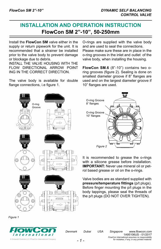
O-ring Groove8” flanges
O-ring Groove10” flanges
Install the FlowCon SM valve either in the supply or return pipework for the unit. It is recommended that a strainer be installed prior to the valve body to prevent damage or blockage due to debris.INSTALL THE VALVE HOUSING WITH THE FLOW DIRECTIONAL ARROW POINT ING IN THE CORRECT DIRECTION.
The valve body is available for double flange connections, i.e figure 1.
O-rings are supplied with the valve body and are used to seal the connections. Please make sure these are in place in the o-ring grooves in the inlet and outlet of the valve body, when installing the housing.
FlowCon SM.6 (8”-10”) contains two o-ring grooves (figure 2). Sealing is done on smallest diameter groove if 8” flanges are used and on the largest diameter groove if 10” flanges are used.
It is recommended to grease the o-rings with a silicone grease before installation.IMPORTANT: Never use mineral oil or pet-rol based grease or oil on the o-rings.
Valve bodies are as standard supplied with pressure/temperature fittings (p/t plugs). Before finger mounting the p/t plugs in the body tappings, please seal the threads of the p/t plugs (DO NOT OVER TIGHTEN).
DYNAMIC SELF BALANCINGCONTROL VALVE
FlowCon SM 2”-10”
FlowCon International assumes no responsibility for mistakes, if any, in any printed material.
Denmark Dubai USA Singapore www.flowcon.com 1A95106US - 01/2017
- 2 -
Figure 5Figure 4
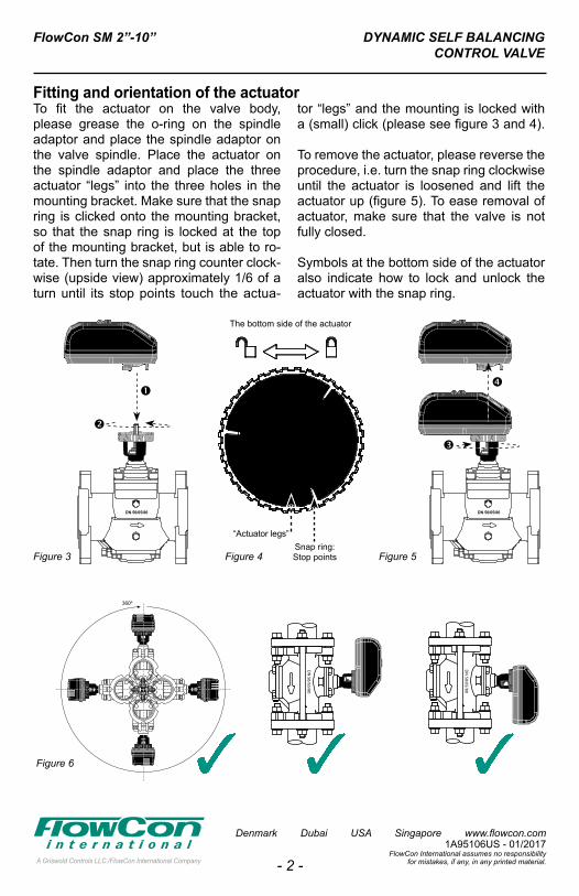
The bottom side of the actuator
“Actuator legs”Snap ring:Stop points
360º
360º 360º
Figure 3
Figure 6
To fit the actuator on the valve body, please grease the o-ring on the spindle adaptor and place the spindle adaptor on the valve spindle. Place the actuator on the spindle adaptor and place the three actuator “legs” into the three holes in the mounting bracket. Make sure that the snap ring is clicked onto the mounting bracket, so that the snap ring is locked at the top of the mounting bracket, but is able to ro-tate. Then turn the snap ring counter clock-wise (upside view) approximately 1/6 of a turn until its stop points touch the actua-
tor “legs” and the mounting is locked with a (small) click (please see figure 3 and 4).
To remove the actuator, please reverse the procedure, i.e. turn the snap ring clockwise until the actuator is loosened and lift theactuator up (figure 5). To ease removal of actuator, make sure that the valve is notfully closed.
Symbols at the bottom side of the actuatoralso indicate how to lock and unlock theactuator with the snap ring.
Fitting and orientation of the actuator
DYNAMIC SELF BALANCINGCONTROL VALVE
FlowCon SM 2”-10”
FlowCon International assumes no responsibility for mistakes, if any, in any printed material.
Denmark Dubai USA Singapore www.flowcon.com 1A95106US - 01/2017
- 3 -
BlackRedWhite
Common24 VAC/VDCAnalog Signal
Analog - No feedback
BlackRedWhite
CommonA+B-
BACnet connection
BlackRedWhite
CommonA+B-
BACnet communication cable
BlackBlueWhiteGreen
Common24 VAC/VDCControl SignalFeedback
Analog - With feedback
Supply24 VAC/VDC
BlackBlueWhiteRedGreen
Common24 VAC/VDCOpen if NC, Close if NOClose if NC, Open if NOFeedback
Digital - 2 position - With feedback
Supply24 VAC/VDC
BlackWhiteRed
CommonDrive CWDrive CCW
Digital - 3 point floating - No feedback
Supply24 VAC/VDC
BlackBlueWhiteRedGreen
Common24 VAC/VDCOpen if NC, Close if NOClose if NC, Open if NOFeedback
Digital - 3 point floating - With feedback
BlackWhiteRed
Supply24 VAC/VDC
CommonDrive CWDrive CCW
Digital - 2 position - No feedback
AnalogBlackRedWhite
Common24 VAC/VDCAnalog Signal
Analog - No feedback
BlackRedWhite
CommonA+B-
BACnet connection
BlackRedWhite
CommonA+B-
BACnet communication cable
BlackBlueWhiteGreen
Common24 VAC/VDCControl SignalFeedback
Analog - With feedback
Supply24 VAC/VDC
BlackBlueWhiteRedGreen
Common24 VAC/VDCOpen if NC, Close if NOClose if NC, Open if NOFeedback
Digital - 2 position - With feedback
Supply24 VAC/VDC
BlackWhiteRed
CommonDrive CWDrive CCW
Digital - 3 point floating - No feedback
Supply24 VAC/VDC
BlackBlueWhiteRedGreen
Common24 VAC/VDCOpen if NC, Close if NOClose if NC, Open if NOFeedback
Digital - 3 point floating - With feedback
BlackWhiteRed
Supply24 VAC/VDC
CommonDrive CWDrive CCW
Digital - 2 position - No feedback Digital - 2 position
BlackRedWhite
Common24 VAC/VDCAnalog Signal
Analog - No feedback
BlackRedWhite
CommonA+B-
BACnet connection
BlackRedWhite
CommonA+B-
BACnet communication cable
BlackBlueWhiteGreen
Common24 VAC/VDCControl SignalFeedback
Analog - With feedback
Supply24 VAC/VDC
BlackBlueWhiteRedGreen
Common24 VAC/VDCOpen if NC, Close if NOClose if NC, Open if NOFeedback
Digital - 2 position - With feedback
Supply24 VAC/VDC
BlackWhiteRed
CommonDrive CWDrive CCW
Digital - 3 point floating - No feedback
Supply24 VAC/VDC
BlackBlueWhiteRedGreen
Common24 VAC/VDCOpen if NC, Close if NOClose if NC, Open if NOFeedback
Digital - 3 point floating - With feedback
BlackWhiteRed
Supply24 VAC/VDC
CommonDrive CWDrive CCW
Digital - 2 position - No feedback
Digital - 3 point floating
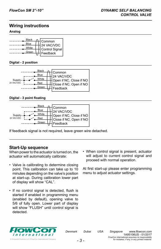
If feedback signal is not required, leave green wire detached.
Wiring instructions
Start-Up sequenceWhen power to the actuator is turned on, the actuator will automatically calibrate:
• Valve is calibrating to determine closing point. This calibration can take up to 10 minutes depending on the valve’s position at start-up. During calibration lower part of display will show “CAL”.
• If no control signal is detected, flush is started if enabled in programming menu (enabled by default), opening valve to 5/6 of fully open. Lower part of display will show “FLUSH” until control signal is detected.
• When control signal is present, actuator will adjust to current control signal and proceed with normal operation.
At first start-up please enter programmingmenu to adjust actuator settings.
DYNAMIC SELF BALANCINGCONTROL VALVE
FlowCon SM 2”-10”
FlowCon International assumes no responsibility for mistakes, if any, in any printed material.
Denmark Dubai USA Singapore www.flowcon.com 1A95106US - 01/2017
- 4 -
*
*
*
*
*
*
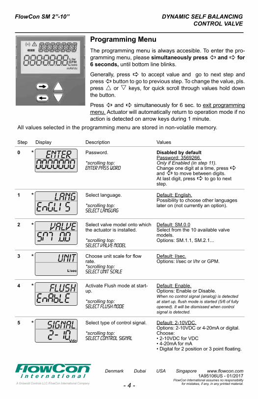
Programming Menu The programming menu is always accesible. To enter the pro-gramming menu, please simultaneously press and for 6 seconds, until bottom line blinks.
Generally, press to accept value and go to next step and press button to go to previous step. To change the value, pls. press or keys, for quick scroll through values hold down the button.
Press and simultaneously for 6 sec. to exit programming menu. Actuator will automatically return to operation mode if no action is detected on arrow keys during 1 minute.
All values selected in the programming menu are stored in non-volatile memory.
Step Display Description Values
0 Password.
*scrolling top:ENTER PASS WORD
Disabled by defaultPassword: 3569266.Only if Enabled (in step 11).Change one digit at a time, press and to move between digits.At last digit, press to go to next step.
1 Select language.
*scrolling top:SELECT LANGUAG
Default: English.Possibility to choose other languages later on (not currently an option).
2 Select valve model onto whichthe actuator is installed.
*scrolling top:SELECT VALVE MODEL
Default: SM.0.0 Select from the 10 available valve models.Options: SM.1.1, SM.2.1...
3 Choose unit scale for flow rate.*scrolling top:SELECT UNIT SCALE
Default: l/sec.Options: l/sec or l/hr or GPM.
4 Activate Flush mode at start-up.
*scrolling top:SELECT FLUSH MODE
Default: Enable.Options: Enable or Disable.When no control signal (analog) is detected at start up, flush mode is started (5/6 of fully opened). It will be dismissed when control signal is detected.
5 Select type of control signal. *scrolling top:SELECT CONTROL SIGNAL
Default: 2-10VDC.Options: 2-10VDC or 4-20mA or digital.Choose: • 2-10VDC for VDC• 4-20mA for mA• Digital for 2 position or 3 point floating.
DYNAMIC SELF BALANCINGCONTROL VALVE
FlowCon SM 2”-10”
FlowCon International assumes no responsibility for mistakes, if any, in any printed material.
Denmark Dubai USA Singapore www.flowcon.com 1A95106US - 01/2017
- 5 -
*
*
*
*
*
*
*
All values selected in the programming menu are stored in non-volatile memory.
Step Display Description Values
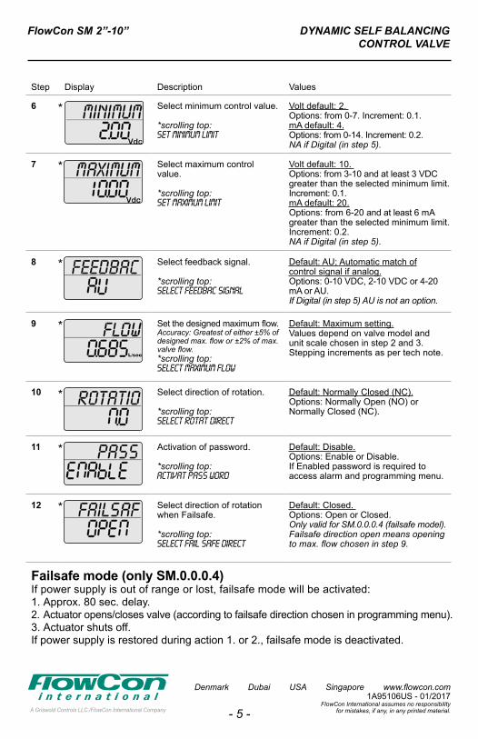
6 Select minimum control value.
*scrolling top:SET MINIMUM LIMIT
Volt default: 2. Options: from 0-7. Increment: 0.1.mA default: 4.Options: from 0-14. Increment: 0.2.NA if Digital (in step 5).
7 Select maximum control value.
*scrolling top:SET MAXIMUM LIMIT
Volt default: 10. Options: from 3-10 and at least 3 VDC greater than the selected minimum limit. Increment: 0.1.mA default: 20.Options: from 6-20 and at least 6 mA greater than the selected minimum limit. Increment: 0.2.NA if Digital (in step 5).
8 Select feedback signal.
*scrolling top:SELECT FEEDBAC SIGNAL
Default: AU; Automatic match ofcontrol signal if analog.Options: 0-10 VDC, 2-10 VDC or 4-20 mA or AU.If Digital (in step 5) AU is not an option.
9 Set the designed maximum flow.Accuracy: Greatest of either ±5% of designed max. flow or ±2% of max. valve flow.*scrolling top:SELECT MAXIMUM FLOW
Default: Maximum setting.Values depend on valve model and unit scale chosen in step 2 and 3.Stepping increments as per tech note.
10 Select direction of rotation.
*scrolling top:SELECT ROTAT DIRECT
Default: Normally Closed (NC).Options: Normally Open (NO) orNormally Closed (NC).
11 Activation of password.
*scrolling top:ACTIVAT PASS WORD
Default: Disable.Options: Enable or Disable.If Enabled password is required toaccess alarm and programming menu.
12 Select direction of rotation when Failsafe.
*scrolling top:SELECT FAIL SAFE DIRECT
Default: Closed. Options: Open or Closed.Only valid for SM.0.0.0.4 (failsafe model). Failsafe direction open means opening to max. flow chosen in step 9.
Failsafe mode (only SM.0.0.0.4)If power supply is out of range or lost, failsafe mode will be activated:1. Approx. 80 sec. delay.2. Actuator opens/closes valve (according to failsafe direction chosen in programming menu).3. Actuator shuts off.If power supply is restored during action 1. or 2., failsafe mode is deactivated.
Step Display Description Values
0 Password.
*scrolling top:ENTER PASS WORD
Disabled by defaultPassword: 3569266.Only if Enabled (in step 11).Change one digit at a time, press and to move between digits.At last digit, press to go to next step.
1 Select language.
*scrolling top:SELECT LANGUAG
Default: English.Possibility to choose other languages later on (not currently an option).
2 Select valve model onto whichthe actuator is installed.
*scrolling top:SELECT VALVE MODEL
Default: SM.0.0 Select from the 10 available valve models.Options: SM.1.1, SM.2.1...
3 Choose unit scale for flow rate.*scrolling top:SELECT UNIT SCALE
Default: l/sec.Options: l/sec or l/hr or GPM.
4 Activate Flush mode at start-up.
*scrolling top:SELECT FLUSH MODE
Default: Enable.Options: Enable or Disable.When no control signal (analog) is detected at start up, flush mode is started (5/6 of fully opened). It will be dismissed when control signal is detected.
5 Select type of control signal. *scrolling top:SELECT CONTROL SIGNAL
Default: 2-10VDC.Options: 2-10VDC or 4-20mA or digital.Choose: • 2-10VDC for VDC• 4-20mA for mA• Digital for 2 position or 3 point floating.
DYNAMIC SELF BALANCINGCONTROL VALVE
FlowCon SM 2”-10”
FlowCon International assumes no responsibility for mistakes, if any, in any printed material.
Denmark Dubai USA Singapore www.flowcon.com 1A95106US - 01/2017
- 6 -
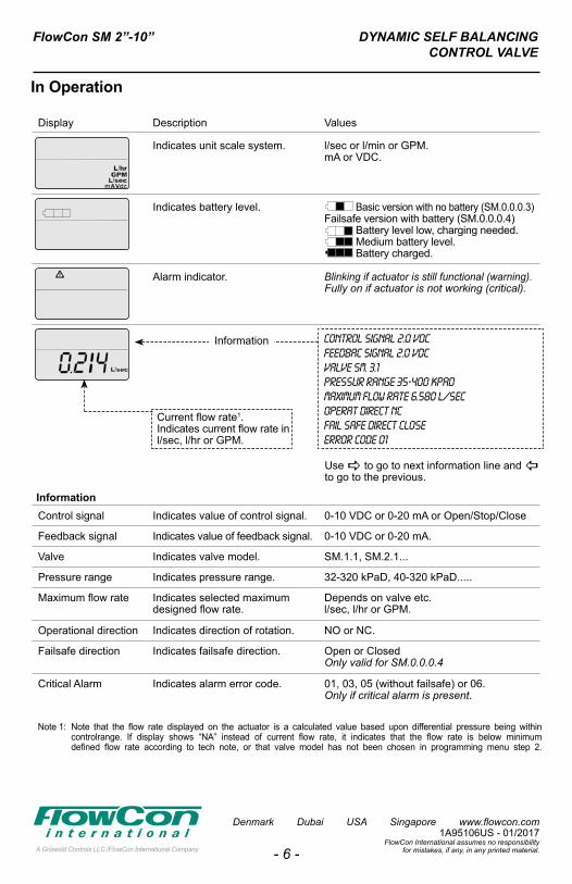
Information
Current flow rate1.Indicates current flow rate inl/sec, l/hr or GPM.
Display Description Values
Indicates unit scale system. l/sec or l/min or GPM.mA or VDC.
Indicates battery level. Basic version with no battery (SM.0.0.0.3)Failsafe version with battery (SM.0.0.0.4) Battery level low, charging needed. Medium battery level. Battery charged.
Alarm indicator. Blinking if actuator is still functional (warning).Fully on if actuator is not working (critical).
CONTROL SIGNAL 2.0 VDCFEEDBAC SIGNAL 2.0 VDCVALVE SM. 3.1pressur range 35-400 kpadMAXIMUM FLOW RATE 6.580 L/SECOPERAT DIRECT NCFAIL SAFE DIRECT CLOSEERROR CODE 01
InformationControl signal Indicates value of control signal. 0-10 VDC or 0-20 mA or Open/Stop/Close
Feedback signal Indicates value of feedback signal. 0-10 VDC or 0-20 mA.
Valve Indicates valve model. SM.1.1, SM.2.1...
Pressure range Indicates pressure range. 32-320 kPaD, 40-320 kPaD.....
Maximum flow rate Indicates selected maximum designed flow rate.
Depends on valve etc.l/sec, l/hr or GPM.
Operational direction Indicates direction of rotation. NO or NC.
Failsafe direction Indicates failsafe direction. Open or ClosedOnly valid for SM.0.0.0.4
Critical Alarm Indicates alarm error code. 01, 03, 05 (without failsafe) or 06.Only if critical alarm is present.
In Operation
Note 1: Note that the flow rate displayed on the actuator is a calculated value based upon differential pressure being within controlrange. If display shows “NA” instead of current flow rate, it indicates that the flow rate is below minimum defined flow rate according to tech note, or that valve model has not been chosen in programming menu step 2.
Use to go to next information line and to go to the previous.
DYNAMIC SELF BALANCINGCONTROL VALVE
FlowCon SM 2”-10”
FlowCon International assumes no responsibility for mistakes, if any, in any printed material.
Denmark Dubai USA Singapore www.flowcon.com 1A95106US - 01/2017
- 7 -
Display Description Values
Indicates unit scale system. l/sec or l/min or GPM.mA or VDC.
Indicates battery level. Basic version with no battery (SM.0.0.0.3)Failsafe version with battery (SM.0.0.0.4) Battery level low, charging needed. Medium battery level. Battery charged.
Alarm indicator. Blinking if actuator is still functional (warning).Fully on if actuator is not working (critical).
CONTROL SIGNAL 2.0 VDCFEEDBAC SIGNAL 2.0 VDCVALVE SM. 3.1pressur range 35-400 kpadMAXIMUM FLOW RATE 6.580 L/SECOPERAT DIRECT NCFAIL SAFE DIRECT CLOSEERROR CODE 01
InformationControl signal Indicates value of control signal. 0-10 VDC or 0-20 mA or Open/Stop/Close
Feedback signal Indicates value of feedback signal. 0-10 VDC or 0-20 mA.
Valve Indicates valve model. SM.1.1, SM.2.1...
Pressure range Indicates pressure range. 32-320 kPaD, 40-320 kPaD.....
Maximum flow rate Indicates selected maximum designed flow rate.
Depends on valve etc.l/sec, l/hr or GPM.
Operational direction Indicates direction of rotation. NO or NC.
Failsafe direction Indicates failsafe direction. Open or ClosedOnly valid for SM.0.0.0.4
Critical Alarm Indicates alarm error code. 01, 03, 05 (without failsafe) or 06.Only if critical alarm is present.
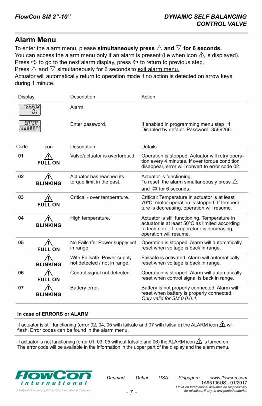
Alarm Menu To enter the alarm menu, please simultaneously press and for 6 seconds.You can access the alarm menu only if an alarm is present (i.e when icon ⚠ is displayed).Press to go to the next alarm display, press to return to previous step.Press and simultaneously for 6 seconds to exit alarm menu.Actuator will automatically return to operation mode if no action is detected on arrow keysduring 1 minute.
In case of ERRORS or ALARM
If actuator is still functioning (error 02, 04, 05 with failsafe and 07 with failsafe) the ALARM icon ⚠ will flash. Error codes can be found in the alarm menu.
If actuator is not functioning (error 01, 03, 05 without failsafe and 06) the ALARM icon ⚠ is turned on.The error code will be available in the information in the upper part of the display and the alarm menu.
Display Description Action
Alarm.
Enter password. If enabled in programming menu step 11Disabled by default. Password: 3569266.
Code Icon Description Details
01 Valve/actuator is overtorqued. Operation is stopped. Actuator will retry opera-tion every 4 minutes. If over torque condition disappear, error will convert to error code 02.
02 Actuator has reached its torque limit in the past.
Actuator is functioning.To reset the alarm simultaneously press and for 6 seconds.
03 Critical - over temperature. Critical: Temperature in actuator is at least 70ºC, motor operation is stopped. If tempera-ture is decreasing, operation will resume.
04 High temperature. Actuator is still functioning. Temperature in actuator is at least 50ºC as limited accordingto tech note. If temperature is decreasing, operation will resume.
05 No Failsafe: Power supply not in range.
Operation is stopped. Alarm will automatically reset when voltage is back in range.
With Failsafe: Power supply not detected / not in range.
Failsafe is activated. Alarm will automatically reset when voltage is back in range.
06 Control signal not detected. Operation is stopped. Alarm will automatically reset when control signal is back in range.
07 Battery error. Battery is not properly connected. Alarm will reset when battery is properly connected.Only valid for SM.0.0.0.4.
FULL ON
BLINKING
BLINKING
BLINKING
BLINKING
FULL ON
FULL ON
FULL ON
DYNAMIC SELF BALANCINGCONTROL VALVE
FlowCon SM 2”-10”
FlowCon International assumes no responsibility for mistakes, if any, in any printed material.
Denmark Dubai USA Singapore www.flowcon.com 1A95106US - 01/2017
- 8 -
Auto-stroke - re-calibrationIn case the valve does not operate as ex-pected, start the auto-stroke sequence to re-calibrate the closing point of the valve and to make sure that the actuator is able to open the valve fully. Press buttons and simultaneously for 6 seconds to start the auto-stroke.
Auto-stroke sequence(display shows: “AUTO STROKE CYCLES”): 1. Valve is closed to determine closing point.2. Valve is opened fully (independent of max. flow chosen).3. System returns to normal operation.
If actuator is not able to open valve fully, an error will be displayed. An auto-stroke cannot be cancelled.
Manual overrideManual override is used to temporarily set the position of the valve regardless of the settings and control signal for the actuator.1. Turn off power to the actuator.2. Remove actuator from valve as de- scribed.3. Turn spindle to the relevant position (Clock-wise to close valve, counter clockwise to open valve). Be sure not to use more than 10 Nm torque. Please protect actuator from water while not on valve.4. Re-mount actuator on valve as de- scribed.5. Turn on power to the actuator when nor- mal operation is needed.
GeneralWater must always be suitable treated, clean and free of debris. It is recommended that a strainer be installed prior to the valve body to prevent damage or blockage due to debris. Ensure that the valve is not in the fully closed position when filling the system with water. Further, it is recommended not to exceed maximum differential pressure control range.
Warranty obligationFailure to abide by all recommendations as per this installation and operation in-struction will void warranty.
Do not remove cover from actuator. Open-ing cover will void warranty.
When manually operating the valve (ac-tuator disconnected) do not use more than 10 Nm torgue. Using more than 10 Nm torgue will void warranty.
For latest updates pls. see www.flowcon.com