Embed Size (px)
Citation preview
44
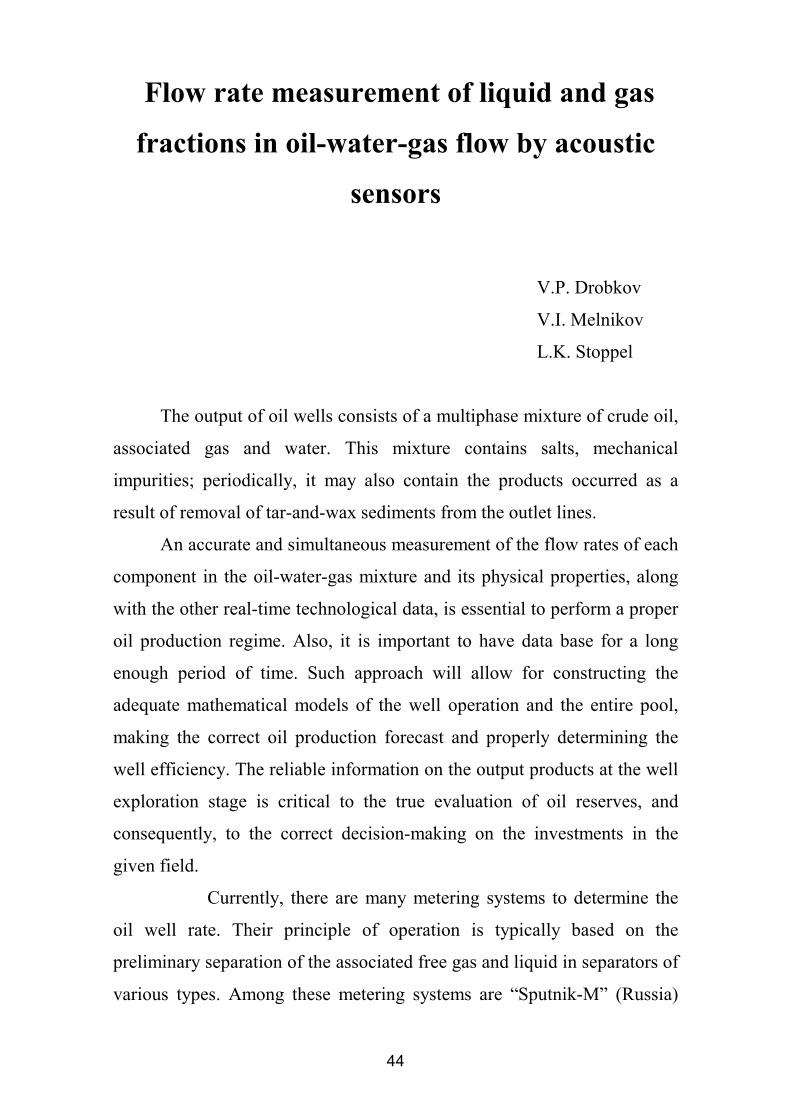
Flow rate measurement of liquid and gas
fractions in oil-water-gas flow by acoustic
sensors
V.P. Drobkov
V.I. Melnikov
L.K. Stoppel
The output of oil wells consists of a multiphase mixture of crude oil,
associated gas and water. This mixture contains salts, mechanical
impurities; periodically, it may also contain the products occurred as a
result of removal of tar-and-wax sediments from the outlet lines.
An accurate and simultaneous measurement of the flow rates of each
component in the oil-water-gas mixture and its physical properties, along
with the other real-time technological data, is essential to perform a proper
oil production regime. Also, it is important to have data base for a long
enough period of time. Such approach will allow for constructing the
adequate mathematical models of the well operation and the entire pool,
making the correct oil production forecast and properly determining the
well efficiency. The reliable information on the output products at the well
exploration stage is critical to the true evaluation of oil reserves, and
consequently, to the correct decision-making on the investments in the
given field.
Currently, there are many metering systems to determine the
oil well rate. Their principle of operation is typically based on the
preliminary separation of the associated free gas and liquid in separators of
various types. Among these metering systems are “Sputnik-M” (Russia)
45
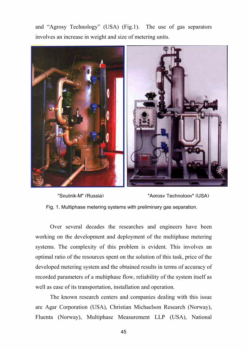
and “Agrosy Technology” (USA) (Fig.1). The use of gas separators
involves an increase in weight and size of metering units.
Over several decades the researches and engineers have been
working on the development and deployment of the multiphase metering
systems. The complexity of this problem is evident. This involves an
optimal ratio of the resources spent on the solution of this task, price of the
developed metering system and the obtained results in terms of accuracy of
recorded parameters of a multiphase flow, reliability of the system itself as
well as ease of its transportation, installation and operation.
The known research centers and companies dealing with this issue
are Agar Сorporation (USA), Christian Michaelson Research (Norway),
Fluenta (Norway), Multiphase Measurement LLP (USA), National
Fig. 1. Multiphase metering systems with preliminary gas separation.
"Sputnik-M" (Russia) "Agrosy Technology" (USA)
46
Engineering Laboratory UK (Great Britain), Ohio State University (USA)
and Southwest Research Institute (USA). More details on the current status
of the problem can be obtained from the materials of the international
conference «Multiphase Metering Technology Forum» arranged annually
by Ohio State University in Houston (USA).
Various measuring techniques are employed to determine the flow
rates of multiphase streams. These techniques are based on the recording of
changes in different physical values of a sounded fluid: electric resistance,
dielectric constant, acoustic impedance in the ultrasonic range, values of
acoustic noises in the audible range, kinetic energy of liquid and gas
phases, fluctuations in the mixture density, nuclear magnetic resonance,
etc.
The multiphase metering systems utilize both a contact method of
measurement with transducers of various types and design and a non-
contact method, for example, gamma-ray technique is used to measure
fluid.
It should be noted that although there exists great diversity of
techniques for measuring the individual physical properties of the mixture,
the common concept is used to determine the flow rates of the components
present in the multiphase flow. This includes the following: the volumetric
flow rate of the multiphase mixture is measured, then, volumetric gas
content of the sounded fluid and volume concentration of water in the
water-oil emulsion are determined.
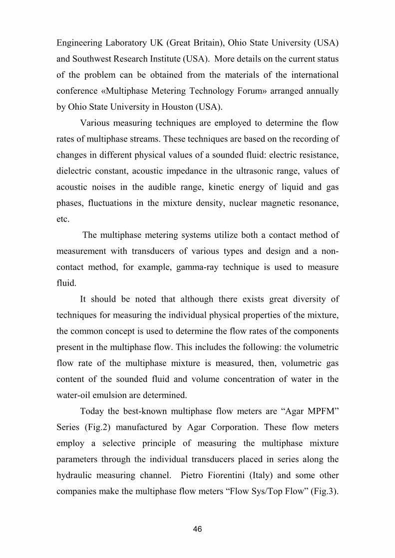
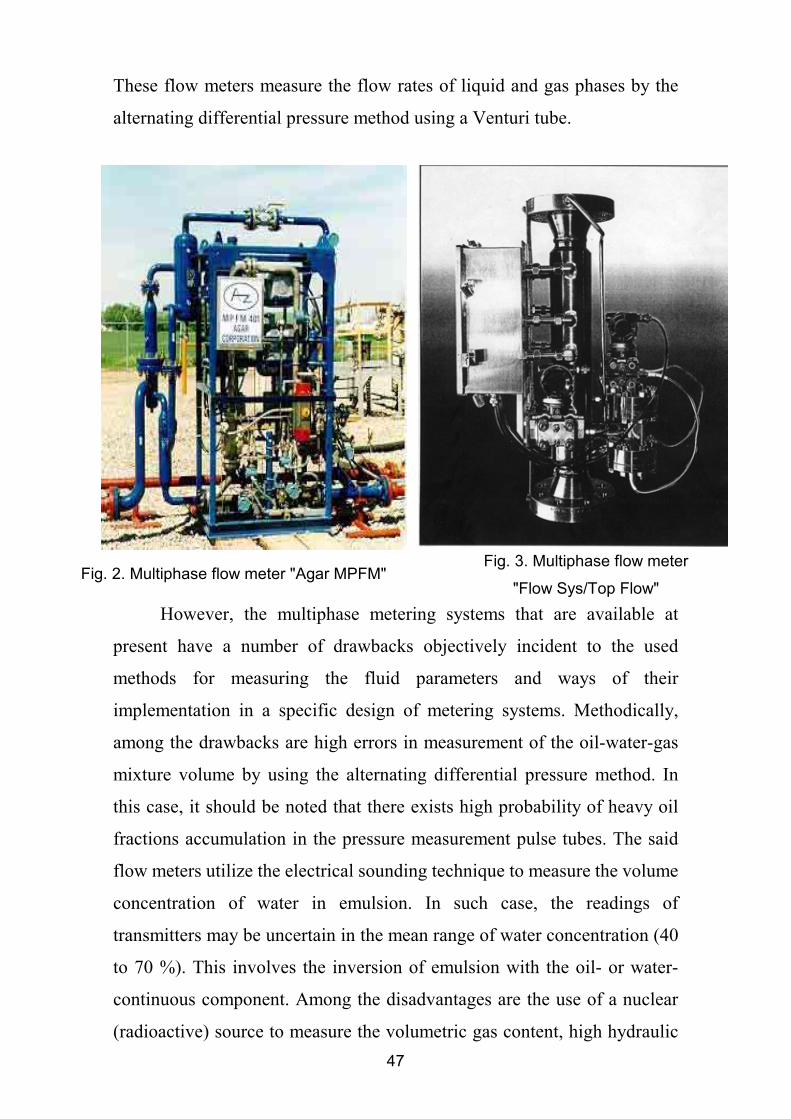
Today the best-known multiphase flow meters are “Agar MPFM”
Series (Fig.2) manufactured by Agar Сorporation. These flow meters
employ a selective principle of measuring the multiphase mixture
parameters through the individual transducers placed in series along the
hydraulic measuring channel. Pietro Fiorentini (Italy) and some other
companies make the multiphase flow meters “Flow Sys/Top Flow” (Fig.3).
47
These flow meters measure the flow rates of liquid and gas phases by the
alternating differential pressure method using a Venturi tube.
However, the multiphase metering systems that are available at
present have a number of drawbacks objectively incident to the used
methods for measuring the fluid parameters and ways of their
implementation in a specific design of metering systems. Methodically,
among the drawbacks are high errors in measurement of the oil-water-gas
mixture volume by using the alternating differential pressure method. In
this case, it should be noted that there exists high probability of heavy oil
fractions accumulation in the pressure measurement pulse tubes. The said
flow meters utilize the electrical sounding technique to measure the volume
concentration of water in emulsion. In such case, the readings of
transmitters may be uncertain in the mean range of water concentration (40
to 70 %). This involves the inversion of emulsion with the oil- or water-
continuous component. Among the disadvantages are the use of a nuclear
(radioactive) source to measure the volumetric gas content, high hydraulic
Fig. 2. Multiphase flow meter "Agar MPFM"Fig. 3. Multiphase flow meter
"Flow Sys/Top Flow"
48
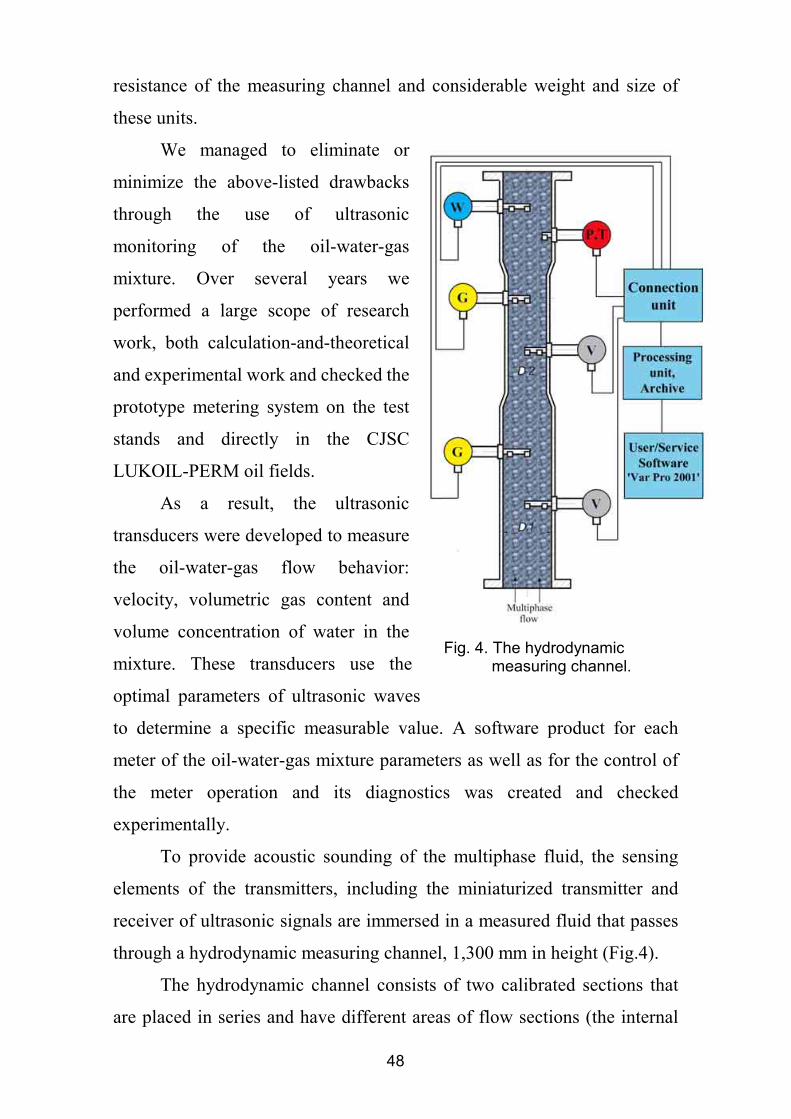
Fig. 4. The hydrodynamic measuring channel.
resistance of the measuring channel and considerable weight and size of
these units.
We managed to eliminate or
minimize the above-listed drawbacks
through the use of ultrasonic
monitoring of the oil-water-gas
mixture. Over several years we
performed a large scope of research
work, both calculation-and-theoretical
and experimental work and checked the
prototype metering system on the test
stands and directly in the CJSC
LUKOIL-PERM oil fields.
As a result, the ultrasonic
transducers were developed to measure
the oil-water-gas flow behavior:
velocity, volumetric gas content and
volume concentration of water in the
mixture. These transducers use the
optimal parameters of ultrasonic waves
to determine a specific measurable value. A software product for each
meter of the oil-water-gas mixture parameters as well as for the control of
the meter operation and its diagnostics was created and checked
experimentally.
To provide acoustic sounding of the multiphase fluid, the sensing
elements of the transmitters, including the miniaturized transmitter and
receiver of ultrasonic signals are immersed in a measured fluid that passes
through a hydrodynamic measuring channel, 1,300 mm in height (Fig.4).
The hydrodynamic channel consists of two calibrated sections that
are placed in series and have different areas of flow sections (the internal
49
diameters of sections are 60 and 42.4 mm). The velocity and volumetric
gas content transmitters are located in the wide and narrow sections of the
measuring channel, in the hydrodynamic stabilization areas, with the
sensing elements of each transmitter at the center and a peripheral part of
the flow section of the channel. Such measuring technique eliminated the
need to consider the gas phase slip velocity when calculating the
volumetric flow rates of liquid and gas phases in the bubbly regime of the
multiphase mixture flow. This method for calculating the phase flow rates
is discussed in detail in Mr. V. Drobkov’s paper «On phases volume flow
evaluations in upward gas liquid flow» presented at this conference. The
volume water concentration, temperature and pressure transmitters for the
sounded fluid are installed at the outlet of the measuring channel.
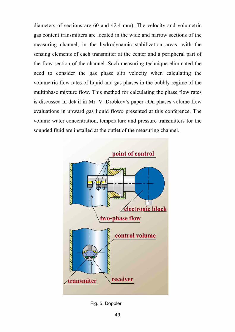
Fig. 5. Doppler
50
The velocity transmitters (Fig.5) employ the Doppler method for
measuring this parameter. In these transmitters, velocity is converted into
the Doppler shift in frequency of an ultrasonic signal reflected from the
acoustic heterogeneity of the sounded fluid.
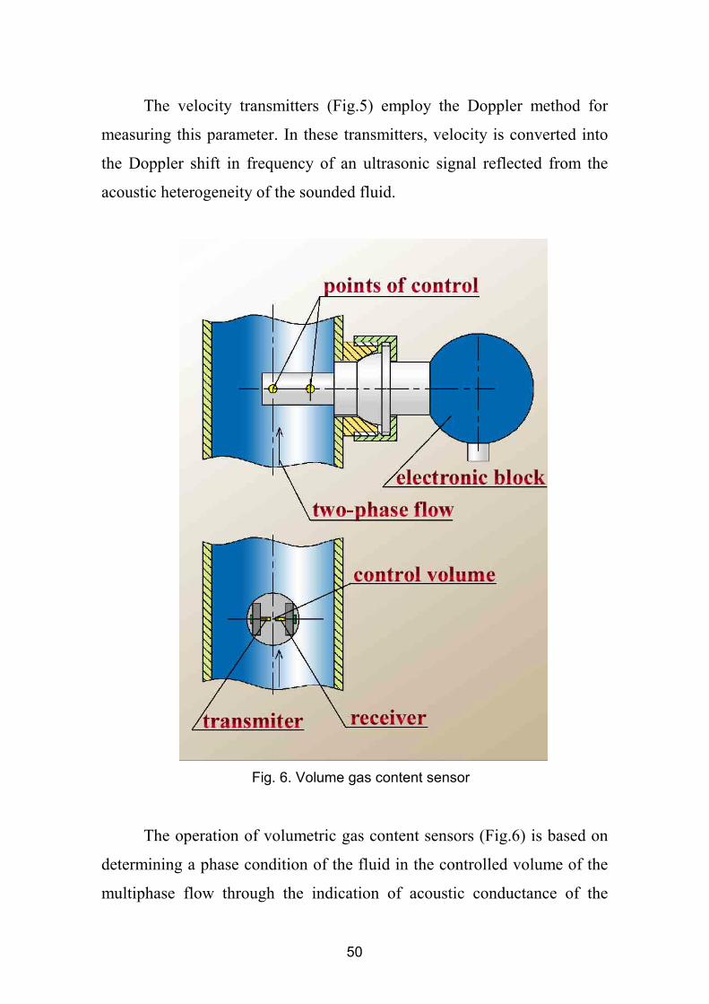
The operation of volumetric gas content sensors (Fig.6) is based on
determining a phase condition of the fluid in the controlled volume of the
multiphase flow through the indication of acoustic conductance of the
Fig. 6. Volume gas content sensor
51
sounded fluid flowing in the gap between transmitter and receiver of
ultrasonic waves.
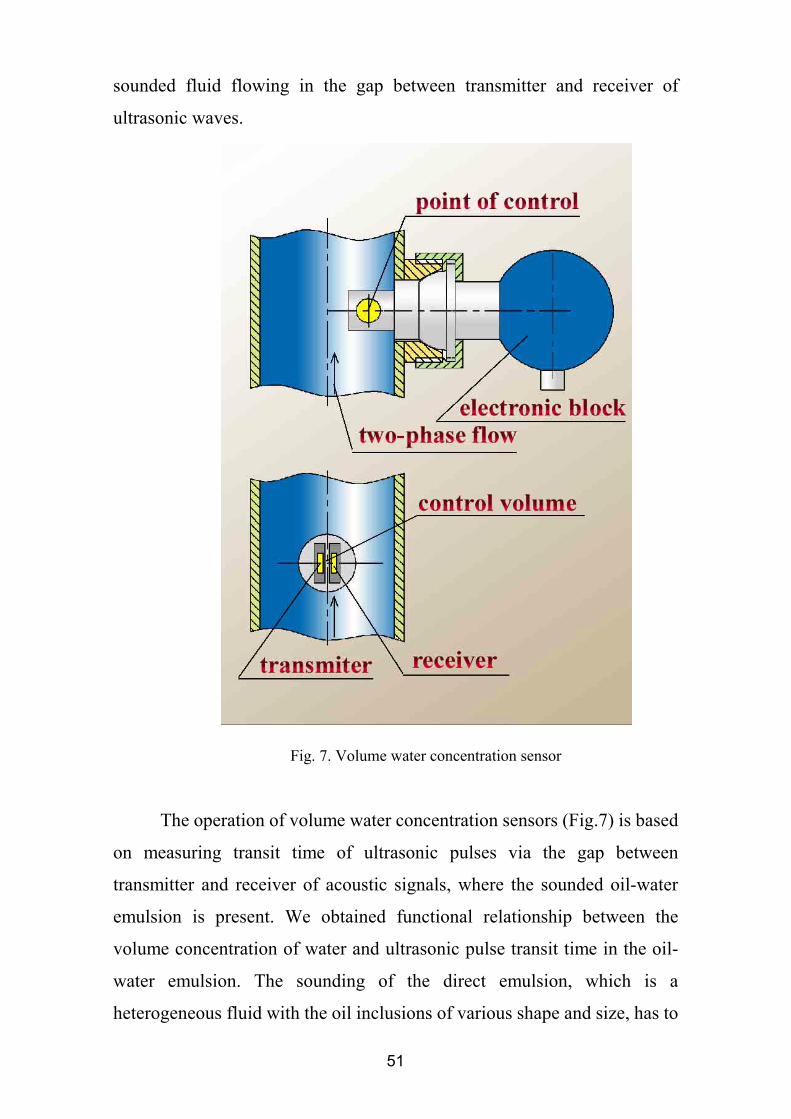
The operation of volume water concentration sensors (Fig.7) is based
on measuring transit time of ultrasonic pulses via the gap between
transmitter and receiver of acoustic signals, where the sounded oil-water
emulsion is present. We obtained functional relationship between the
volume concentration of water and ultrasonic pulse transit time in the oil-
water emulsion. The sounding of the direct emulsion, which is a
heterogeneous fluid with the oil inclusions of various shape and size, has to
Fig. 7. Volume water concentration sensor
52
do with random occurrence of the emulsion components in the controlled
volume of fluid. In view of this fact, a change in the acoustic impedance in
the given volume also occurs at random. This is taken into consideration in
the input signal processing algorithm. The value of volume concentration
of water in the invert emulsion is determined by the amount of water
globules in the volume element of the measured fluid. There is a
relationship between water-cut of emulsion of this type and rate of
ultrasonic pulse propagation through the controlled volume of the fluid.
Program for computing the volume concentration of water automatically
takes into account the type of emulsion and determines a signal processing
algorithm with consideration for the temperature calibration characteristic
of the measured fluid and concentration of mineral salts in water.
The flow parameter meters have the microprocessors fitted with an
adequate program for processing the transmitter signals. The signals
converted into digital codes are sent, via the RS-485 industrial interface
and installation distributor, to the controller designed for the electric
connection of primary transducers with the external computer, data
accumulation and recording into a nonvolatile history file for further
transfer of historical data on the external computer demand via the RS-232
channel. The accumulated data can be stored within one month. The
computation operations and representation of the results in a graphical and
tabular format are carried out in situ with a portable computer of
«Notebook» type. It may be also possible to connect the external computer
via radio-modem or line communication as well as to use a special reading
device.
The external computer has a program for calculating the component
flow rates of the oil-water-gas mixture («Var Pro 2000»). The program
automatically considers a change in the multiphase flow regime: from
bubbly to slug and annular. The program also includes correction of
parameters on the fluid temperature, pressure and viscosity. This program
53
provides high reliability of calculated data on the flow rates of oil-water-
gas mixture, because it analyses and compares the initial data acquired
from the transducers installed in various calibrated sections of the
hydrodynamic channel. The program compares the values of component
volumes passed through various sections of the measuring channel, which
should be equal under normal operation of the «Ultraflow» system. In case
the values are not equal, the program identifies a cause of deviation. To
enhance reliable operation of the metering system, the «Var Рro 2000»
program also provides control over the accuracy of measured parameter
values by comparison with the obtained calculated data of these values.
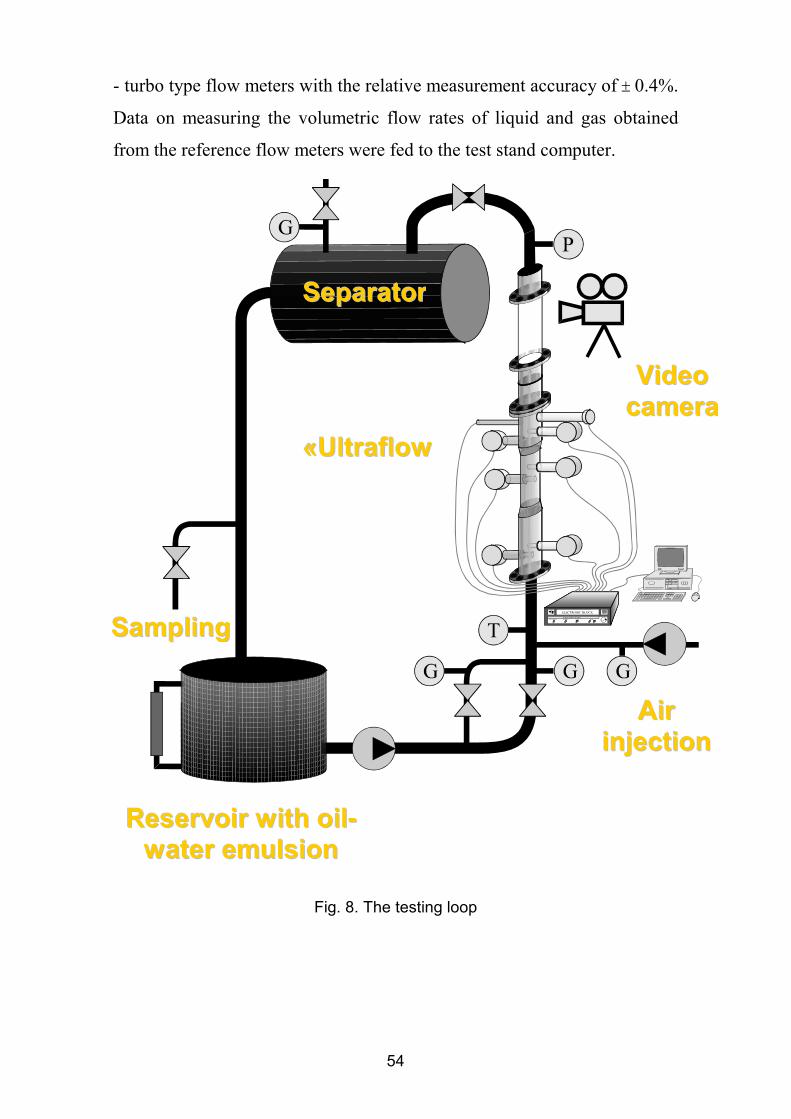
The developed «Ultraflow» metering system was tested on a
specially made flow loop (Fig.8). The test loop allows the implementation
of various flow regimes of the multiphase mixture in the range of
consumption gas content from 0 to 98 %. The liquid flow rate can be set in
the range between 0 (bubbly regime) to 140 m3 per day.
A multiphase mixture consisting of industrial oil, water with
different salinity and gas (air) was used as the working fluid. This working
fluid was selected based on the fact that the physical parameters of
industrial oil, including ultrasound velocity, are close to the mean values of
crude oil parameters.
The water-oil emulsion with a strictly specified ratio of volume
concentration of water and oil was prepared in the bottom dump tank. The
emulsion composition was controlled by the optical methods. The prepared
emulsion was fed via a circulating pump to the gas/liquid mixer at the test
stand. The flow rate of the fed liquid was determined by the reference mass
flow meters with the measuring range of 0.1 – 1.0 t/hr and 0.3-5.6 t/hr and
relative measurement accuracy of ± 0.1%.
The gas (air) flow rate was measured by the reference flow meters
with the measuring range of 1-10 and 10-100 m3/hr and measurement
accuracy of 1.0 %, and in case of small gas flow rates – by using the roller
54
- turbo type flow meters with the relative measurement accuracy of ± 0.4%.
Data on measuring the volumetric flow rates of liquid and gas obtained
from the reference flow meters were fed to the test stand computer.
SSaammpplliinngg
RReesseerrvvooiirr wwiitthh ooiill--wwaatteerr eemmuullssiioonn
AAiirr iinnjjeeccttiioonn
««UUllttrraaffllooww
SSeeppaarraattoorr
VViiddeeoo ccaammeerraa
Fig. 8. The testing loop
55
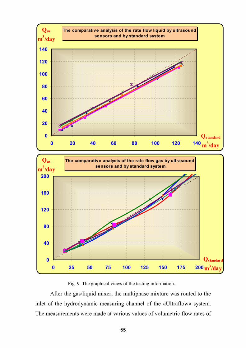
After the gas/liquid mixer, the multiphase mixture was routed to the
inlet of the hydrodynamic measuring channel of the «Ultraflow» system.
The measurements were made at various values of volumetric flow rates of
The comparative analysis of the rate flow liquid by ultrasound sensors and by standard system
0
20
40
60
80
100
120
140
0 20 40 60 80 100 120 140Qstandard
m3/day
Qus
m3/day
The comparative analysis of the rate flow gas by ultrasound sensors and by standard system
0
40
80
120
160
200
0 25 50 75 100 125 150 175 200Qstandard
m3/day
Qus
m3/day
Fig. 9. The graphical views of the testing information.
56
liquid and gas. The liquid flow range was between 0 and 140 m3 per day.
The gas flow range varied from 0 to 400 m3 per day at the operating
parameters of the measured fluid. Data on the volumetric flow rates of the
components generated by the reference flow meters and «Ultraflow»
system were transmitted to the test stand computer where the measurement
results were compared. The obtained data were represented in tabular and
graphical format. Example of the graphical data representation is illustrated
in Fig. 9.
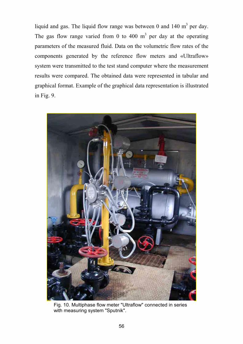
Fig. 10. Multiphase flow meter "Ultraflow" connected in series with measuring system "Sputnik".
57
To conduct the commercial tests, at the end of September, 2001 a
prototype «Ultraflow» metering system was installed in the pipeline at the
inlet of the «Sputnik» field metering system determining the oil well rates
in the CJSC LUKOIL-PERM oil field (Fig.10). To date no faults were
found with the operation of the metering complex. The accumulated
information is periodically read out by the oil field specialists from storage
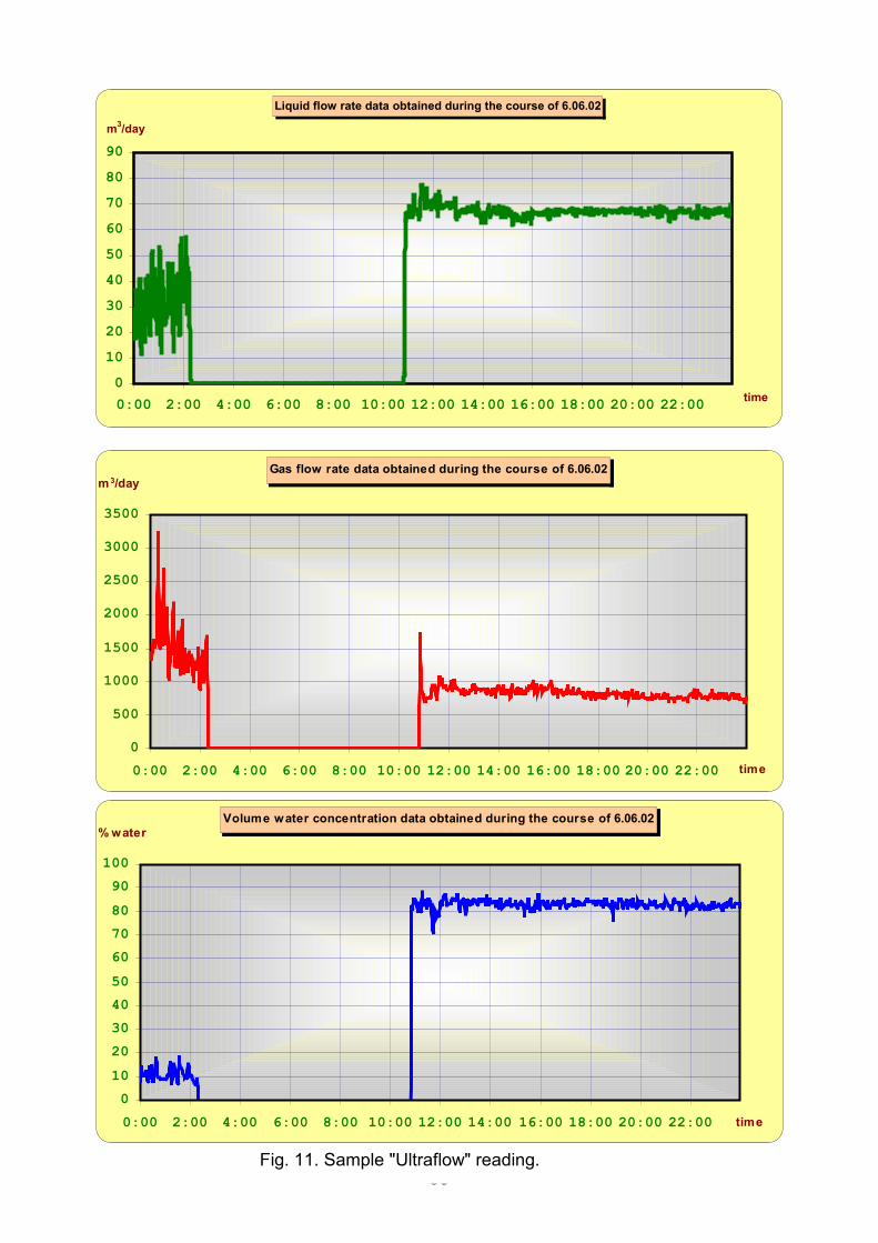
of the controller of the metering system. The examples of measuring the oil
well rates by using the «Ultraflow» system are presented in Fig. 11.
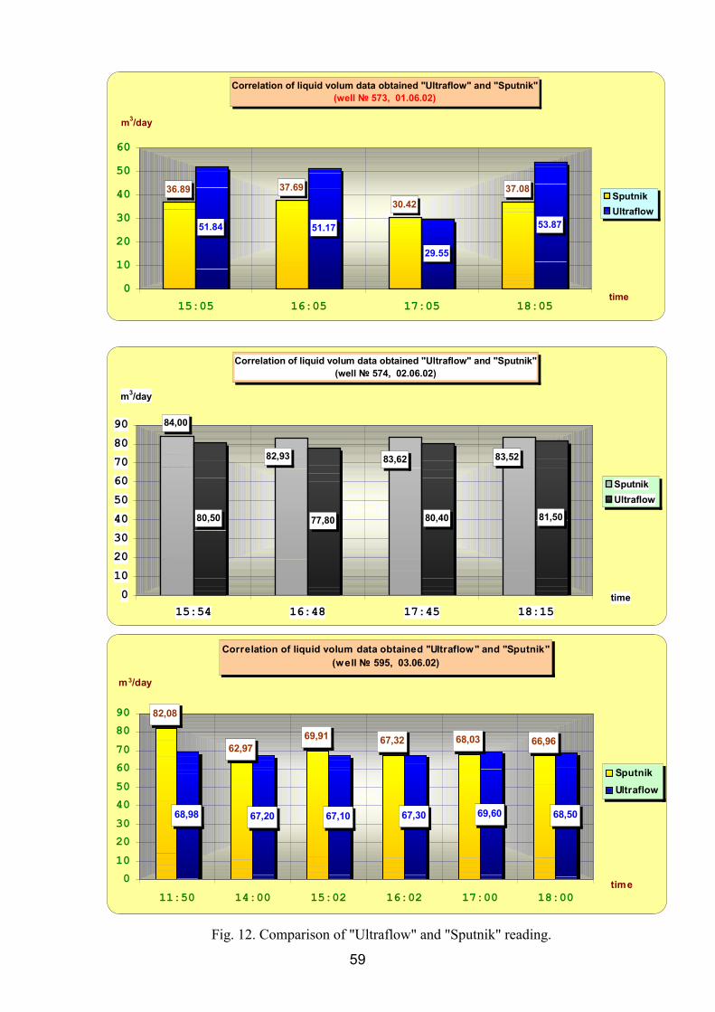
Fig.12 shows the random comparison of volumetric flow rates of
liquid and volume concentration of water based on the readings of the
«Ultraflow» system and readings of a regular liquid volume meter of the
«Sputnik» system. The analysis of the given data shows that the ratio
between the readings of the «Ultraflow» and «Sputnik» systems with
respect to the volumetric flow rates of liquid is not stable. We can look at
two cases here. In Case I, the readings of the field liquid meter are little
higher that those of the «Ultraflow» system. This is typical for the majority
of wells (well nos. 292, 574 and 595). In Case II, the readings of the
«Ultraflow» system exceed the readings of this meter (well nos. 573 and
596). The higher readings of the «Sputnik» liquid meter are related to an
incomplete separation of free gas in the separator of the «Sputnik»
metering system. This occurs where the output of the oil well liquid
product is high. The reason is that if the output is high, time required to
accumulate liquid in a separation tank and accordingly, time required to
remove the gas inclusions from the emulsion is reduced. Some amount of
free gas (~10-15%) had no time to separate. It is common knowledge that
the gas inclusion rise velocity is determined by its size and emulsion
viscosity. The given conditions: separation time, size of gas inclusions and
emulsion viscosity determine the amount of free gas reaching the
measurement chamber of the «Sputnik» liquid meter. This results in an
increase of its readings.
58
Liquid flow rate data obtained during the course of 6.06.02
0102030405060708090
0:00 2:00 4:00 6:00 8:00 10:00 12:00 14:00 16:00 18:00 20:00 22:00 time
m3/day
Gas flow rate data obtained during the course of 6.06.02
0500
100015002000250030003500
0:00 2:00 4:00 6:00 8:00 10:00 12:00 14:00 16:00 18:00 20:00 22:00 time
m 3/day
Volume water concentration data obtained during the course of 6.06.02
0102030405060708090
100
0:00 2:00 4:00 6:00 8:00 10:00 12:00 14:00 16:00 18:00 20:00 22:00 time
% water
Fig. 11. Sample "Ultraflow" reading.
59
Correlation of liquid volum data obtained "Ultraflow" and "Sputnik" (well № 573, 01.06.02)
36.89 37.6930.42
37.08
51.84 51.17
29.55
53.87
0102030405060
15:05 16:05 17:05 18:05 time
m3/day
SputnikUltraflow
Correlation of liquid volum data obtained "Ultraflow" and "Sputnik" (well № 574, 02.06.02)
84,00
80,50 77,80 80,40 81,50
82,93 83,62 83,52
0102030405060708090
15:54 16:48 17:45 18:15time
m3/day
SputnikUltraflow
Correlation of liquid volum data obtained "Ultraflow" and "Sputnik" (well № 595, 03.06.02)
82,08
62,9769,91 67,32 68,03 66,96
68,98 67,20 67,10 67,30 69,60 68,50
0102030405060708090
11:50 14:00 15:02 16:02 17:00 18:00time
m3/day
SputnikUltraflow
Fig. 12. Comparison of "Ultraflow" and "Sputnik" reading.
60
In Case II, the situation is opposite: a decrease in the liquid meter
readings in relation to the readings of the «Ultraflow» system. This is
caused by two cases. The first case involves the ingress of products,
occurred as a result of removing the tar and wax sediments from the well
pipes, into the measurement chamber of the liquid meter. This is supported
by the fact that when taking measurement in well no. 573, a scraper was in
operation. The second case requires a detailed explanation. When
considering the gas separation process in the «Sputnik» separator, attention
should be given to the value of a true volumetric gas content in the mixture
entering the separator. When taking measurements in wells no. 573 and
596, this value was in the range from 73.1 to 82.3% according to the
readings of the «Ultraflow» system. This corresponds to the transfer from
the slug to annular flow regime in the feed pipeline. In this case, large
volumes of gas separated from liquid enter the separator. This leads to an
efficient separation of gas phase from liquid in the gravity separation
section. Accordingly, gas is adequately separated in the accumulating zone
of the separator, and a well-separated liquid is fed to the inlet of the
measuring chamber of liquid meter. The difference between the viscosity
values of water on which the meter-flow meters are calibrated and those of
liquid products of oil wells results in a decrease of the readings of the
«Sputnik» liquid meter.
As mentioned in the second part of the paper, there was no
opportunity to compare the results of measuring free gas by using the
«Sputnik» regular flow meter and «Ultraflow» metering system. However,
if we compare the dynamics of changes in gas and liquid flow rates, it
might be pointed out that the ratio of these flow rates is fairly stable. This is
good indirect evidence that the readings of the «Ultraflow» metering
system are reliable.
61
CONCLUSION 1. The correctness of technical solutions implemented in the
«Ultraflow» metering system to determine the flow rates of the multiphase stream by local acoustic sounding of the fluid has been confirmed.
2. The operability of the «Ultraflow» metering system has been
confirmed under trial operation within the entire specified ranges for
measuring the oil-water-gas mixture parameters:
• Gas content (the range of measured volumetric gas content was
from 0 to 98 %);
• Water-cut (the range was between 0 and 100 %),
• The range of measured liquid flow rates varied from 35 to 90 m3
per day,
• The range of measured gas flow rates varied from 320 to 3,600
nm3 per day.
• The obtained data testify that the «Ultraflow» system provides a stable measurement of the well rates within the entire spectrum of flow regimes of the oil-water-gas mixture without having first to separate out free gas.
3. The developed signal processing algorithms adequately reflect the composition of the oil-water-gas mixture and the actual fluid flow processes in the outlet pipelines of the oil production wells.
4. The design features of the «Ultraflow» metering system allow its use to measure the output of oil well products with high viscosity.