Embed Size (px)
Citation preview

Flow mediated interactions between two cylinders at finite Re numbersMattia Gazzola, Chloe Mimeau, Andrew A. Tchieu, and Petros Koumoutsakos Citation: Phys. Fluids 24, 043103 (2012); doi: 10.1063/1.4704195 View online: http://dx.doi.org/10.1063/1.4704195 View Table of Contents: http://pof.aip.org/resource/1/PHFLE6/v24/i4 Published by the American Institute of Physics. Related ArticlesHydrodynamic interaction of oblique sheets in tandem arrangement Phys. Fluids 25, 011902 (2013) Effect of density stratification on vortex merger Phys. Fluids 25, 016601 (2013) Vorticity alignment of rigid fibers in an oscillatory shear flow: Role of confinement Phys. Fluids 24, 121702 (2012) Non-invasive determination of external forces in vortex-pair-cylinder interactions Phys. Fluids 24, 061903 (2012) Finite Rossby radius effects on vortex motion near a gap Phys. Fluids 24, 066601 (2012) Additional information on Phys. FluidsJournal Homepage: http://pof.aip.org/ Journal Information: http://pof.aip.org/about/about_the_journal Top downloads: http://pof.aip.org/features/most_downloaded Information for Authors: http://pof.aip.org/authors
Downloaded 11 Mar 2013 to 128.148.252.35. Redistribution subject to AIP license or copyright; see http://pof.aip.org/about/rights_and_permissions

PHYSICS OF FLUIDS 24, 043103 (2012)
Flow mediated interactions between two cylindersat finite Re numbers
Mattia Gazzola,1 Chloe Mimeau,2 Andrew A. Tchieu,1
and Petros Koumoutsakos1,a)
1Institute of Computational Science, ETH Zurich, CH-8032 Zurich, Switzerland2Institut de Mathematiques de Bordeaux, Universite Bordeaux 1, Talence 33400, France
(Received 21 December 2011; accepted 29 March 2012; published online 23 April 2012)
We present simulations of two interacting moving cylinders immersed in a two-dimensional incompressible, viscous flow. Simulations are performed by couplinga wavelet-adapted, remeshed vortex method with the Brinkman penalization andprojection approach. This method is validated on benchmark problems and appliedto simulations of a master-slave pair of cylinders. The master cylinder’s motion isimposed and the slave cylinder is let free to respond to the flow. We study the relativerole of viscous and inertia effects in the cylinders interactions and identify relatedsharp transitions in the response of the slave. The observed differences in the behaviorof cylinders with respect to corresponding potential flow simulations are discussed.In addition, it is observed that in certain situations the finite size of the slave cylindersenhances the transport so that the cylinders are advected more effectively than passivetracers placed, respectively, at the same starting position. C© 2012 American Instituteof Physics. [http://dx.doi.org/10.1063/1.4704195]
I. INTRODUCTION
Flows generated by neighboring, moving objects affect their mutual behavior, leading to com-plex collective phenomena emerging from flow-structure interactions. Flow mediated interactionsare intrinsic to natural phenomena such as fish schooling,1, 2 dolphin drafting,3 collective trans-port of suspensions of swimming micro-organisms,4–6 sedimentation of cloud particles,7, 8 clusterformation,9 collision avoidance,10 and egg fertilization.11
The flow physics of these complex interactions has been the subject of experimental andcomputational investigations that aim to unveil governing mechanisms,1–6 and may be in turnexploited for engineering applications ranging from collaborating underwater devices to swarms ofunmanned air vehicles and energy harvesting devices.12, 13
Fluid mediated interactions between moving objects have been investigated in the inertia-lesslimit (Re = 0) via Stokesian dynamics,4, 5, 14–16 and for small, but finite, Reynolds number (Re� 1) through Oseen equations.17 Hydrodynamic interactions in inviscid fluids (Re = ∞) have beenmodeled by potential flow theory for bodies in the presence of free surfaces or bodies immersedin fluids.18, 19 There has been relatively little effort in characterizing hydrodynamic coupling on themotion of immersed objects for finite, moderate Reynolds numbers (1 ≤ Re ≤ 104).10, 20, 21 We notealso the work of Eldredge in developing a formulation that aims to bridge viscous and invisciddescriptions.22 Viscous flow simulations imply the generation of vorticity on the surfaces of thebodies and their interactions are in turn mediated by the transport and dissipation of these vortices.
Varying the ratio between viscous and inertial effects could drastically affect the qualitativeresponse of the system. For example, the onset of schooling seems to coincide with a transition fromviscous to inertial environments (Re ∼ 1000).23, 24 Other examples include the behavior of clustersof particles in a vibrating fluid, where a wide variety of patterns seem to be achievable by varying
a)Electronic mail: [email protected].
1070-6631/2012/24(4)/043103/17/$30.00 C©2012 American Institute of Physics24, 043103-1
Downloaded 11 Mar 2013 to 128.148.252.35. Redistribution subject to AIP license or copyright; see http://pof.aip.org/about/rights_and_permissions

043103-2 Gazzola et al. Phys. Fluids 24, 043103 (2012)
s
Slave Master
s
Master
Slave
Case A1 Case A2
d
SlaveMaster
A
Case B
Ds Dm
Um Um
Ds
Dm
Ds Dm
FIG. 1. Case A1: The set up consists of a master of diameter Dm, forced to move forward at the constant velocity Um , and aslave of diameter Ds, initially located behind the master at the separation distance s. Case A2: The set up consists of a masterof diameter Dm, forced to move forward at the constant velocity Um , and a slave of diameter Ds, initially located abovethe master at the separation distance s. Case B: The set up consists of a master of diameter Dm and a slave of diameter Ds,initially located beside the master at a distance d between the centers of mass. The master is forced to oscillate horizontallyaccording to xm = A sin(2π t/T + φ), xm being the master’s location of its center of mass and A, T , and φ, respectively, theoscillation amplitude, period, and phase.
the Re between 2 and 10,9 or the change in behavior of a gravity-driven dense suspension jet aroundRe ∼ 1.8
In this study, we assess the role of viscous interactions by performing simulations of a prototyp-ical system of interacting bodies consisting of two moving cylinders immersed in a two-dimensionalviscous, incompressible flow. In these simulations the motion of one cylinder (master) is imposed,while the other (slave) is free to respond to the flow. The interaction between master and slave ispurely flow mediated, as no contact is taken into account. Inspired by the works of Nair and Kanso18
and Tchieu et al.19 we consider three configurations as illustrated in Figure 1. In cases A1 and A2(cases described below), the master cylinder moves forward at a constant velocity, while in case B itis forced to oscillate horizontally. We investigate the slave’s response and we compare our findingswith those of inviscid simulations19 in order to assess the role of viscous effects, vorticity generation,and transport on these interactions.
In the present paper, the Navier-Stokes equations are solved using a multiresolution, remeshedvortex method25–27 while the enforcement of the no-slip boundary conditions and the interaction ofthe objects with the surrounding fluid is realized through a Brinkman penalization technique.21, 28, 29
The feedback from the fluid to the freely moving cylinder is captured through the projection methodwhich, by letting the fluid evolve inside the objects, allows one to compute the transfer of linear andangular momenta to the body.21, 29 The remeshed vortex methods are coupled with wavelet basedadaptivity to increase computational efficiency.27, 30–32
The paper is organized as follows. In Sec. II the numerical method is described while itsvalidation and convergence properties are illustrated in Sec. III. Its application to several fluidmediated problems is presented in Sec. IV. The findings of this work are summarized in Sec. V.
II. GOVERNING EQUATIONS AND NUMERICAL METHOD
We consider a two-dimensional incompressible, viscous flow in an infinite domain (�), inwhich a collection of N moving rigid bodies are immersed. We denote with �i, i = 1, . . . , N thesupport of the solids, which are assumed to be of the same density of the fluid (ρ = 1). The flowfield is described by the Navier-Stokes equations (Eqs. (1) and (2)) along with the no-slip boundaryconditions at the surface of the bodies ∂�i (Eq. (3)), while the feedback from the fluid to the freelymoving bodies is governed by Newton’s equation of motion (Eqs. (4) and (5)):
∂u∂t
+ (u · ∇) u = − 1
ρ∇ p + ν∇2u, x ∈ � \ �i , (1)
∇ · u = 0, x ∈ � \ �i , (2)
Downloaded 11 Mar 2013 to 128.148.252.35. Redistribution subject to AIP license or copyright; see http://pof.aip.org/about/rights_and_permissions

043103-3 Gazzola et al. Phys. Fluids 24, 043103 (2012)
u = ui , x ∈ ∂�i , (3)
mi xi = FHi , (4)
d(Ii θi )
dt= MH
i , (5)
where ν is the kinematic viscosity, ui , xi , mi, Ii and θ i are, respectively, the velocity, the position ofthe center of mass, the mass, the moment of inertia, and the angular velocity of the body i, while FH
iand MH
i are the hydrodynamic force and momentum exerted by the fluid on the body i.This system of equations (Eqs. (1)–(5)) is solved by combining remeshed vortex
methods25, 26, 33, 34 and Brinkman penalization28, 35–37 with a projection approach21, 29, 38 and inter-face tracking via level sets. Adding the penalization term and rewriting the momentum equation inits velocity-vorticity (u–ω, where ω = ∇ × u) formulation, Eqs. (1) and (2) become
∂ω
∂t+ ∇ · (uω) = ν∇2ω +
N∑i=1
λ∇ × χi (ui − u), x ∈ � , (6)
∇ · u = 0, x ∈ � , (7)
where χ i are the characteristic functions describing the bodies (one inside, zero outside) andλ � 1 is the penalization factor. The velocity field u is computed from vorticity by solving theunbounded Poisson equation, ∇2u = −∇ × ω. Translational (ut
i ) and rotational (uri ) components of
ui = uti + ur
i are recovered through a projection approach.21, 29 The combined use of such techniquesbypasses the direct estimation of hydrodynamic forces and momenta acting on the immersed bodiesand has been proven to capture accurately the fluid-structure interactions between multiple solidsand the flow.21
Remeshed vortex methods rely on the regularization of the vortex particles on an underlyingcartesian grid and interpolation of the vorticity carried by the particles through a high order ker-nel such as the M ′
4.25, 26, 33, 34 The presence of an underlying regular grid also allows for the fastevaluation of all differential operators using finite difference schemes. Furthermore, the regularizedgrid enables the use of wavelet based adaptivity.30, 31 The grid nodes are adapted according to awavelet multiresolution analysis of the vorticity and velocity fields in order to capture the emergence(grid refinement) or disappearance (grid compression) of small scales. Refinement, computing, andcompression stages regularly alternate while evolving the solution of the system in time.
The solution of the Poisson equation on multiresolution regular grids is obtained through a fastmultiple method (FMM) thus accommodating the far field boundary condition.39, 40 The descriptionof the use of FMM with wavelet based adaptivity for incompressible flows past bluff bodies is givenby Rossinelli.41
refinement: R(ωn and un)|tr , (8)
∇2ψn = −ωn, (9)
un = ∇ × ψn, (10)
ut,ni = 1
mi
∫�
ρχni undx, (11)
θni = 1
Ii
∫�
ρχni
(x − xn
i
) × undx, (12)
ur,ni = θn
i × (x − xn
i
), (13)
unλ = un + λ�t
∑Ni=1 χn
i
(ut,n
i + ur,ni
)1 + λ�t
∑Ni=1 χn
i
, (14)
Downloaded 11 Mar 2013 to 128.148.252.35. Redistribution subject to AIP license or copyright; see http://pof.aip.org/about/rights_and_permissions

043103-4 Gazzola et al. Phys. Fluids 24, 043103 (2012)
ωnλ = ∇ × un
λ, (15)
∂ωnλ
∂t= ν∇2ωn
λ, (16)
∂ωnλ
∂t+ ∇ · (
unλω
nλ
) = 0, (17)
ωn+1 = ωn+1λ , (18)
xn+1i = xn
i + ut,ni �tn, (19)
θn+1i = θn + θn
i �tn, (20)
compression: C(ωn+1 and un+1)|tc . (21)
A time-step from tn to tn + 1 is detailed by Eqs. (8)–(21), assuming that all quantities areknown up to time tn. We denote with R(a)|tr and with C(a)|tc , respectively, the refinement andcompression stages given the wavelet analysis of the field a, using the refinement and compressionthresholds tr and tc. Throughout this work, if not specified otherwise, we consider the domain� = [0, 1] × [0, 1], set λ = 104, tr = 10−4, tc = 10−6, Lagrangian CFL condition42 LCFL = 0.1,and implement χ to follow the definition of Gazzola et al.,21 with smoothing length ε = √
2he,where he is the minimum allowed grid spacing in the multiresolution representation. Hereafter, wewill refer to he as effective grid spacing and to ER = 1/he as the effective resolution. All spatialoperators are discretized with fourth-order accurate schemes, except for the fifth-order averageinterpolating wavelets. Time integration is carried out via Gudonov splitting: the penalization term(Eqs. (14) and (15)) is treated with an implicit Euler scheme, diffusion (Eq. (16)) through a second-order Runge-Kutta scheme coupled with local time stepping,30, 41 particle advection (Eq. (17)) viaa second-order Runge-Kutta scheme and body advection (Eqs. (19) and (20)) with a first-orderexplicit Euler scheme. The present algorithm is implemented using the multi-resolution adaptedgrids (MRAG) library.30, 31, 41
III. VALIDATION
We present a validation study of the computational methods employed in this work (Sec. II).We consider the flow past an impulsively started cylinder to validate the remeshed vortex methodalong with the penalization approach. In addition, we consider the problem of two cylinders in thecourse of a collision and compute the forces induced by the fluid on the two cylinders to validatethe numerical scheme for fluid mediated interactions. The space and time convergence properties ofthe numerical scheme (Sec. II) are investigated by performing simulations for the test case B.
A. Flow past impulsively started cylinder at Re = 1000
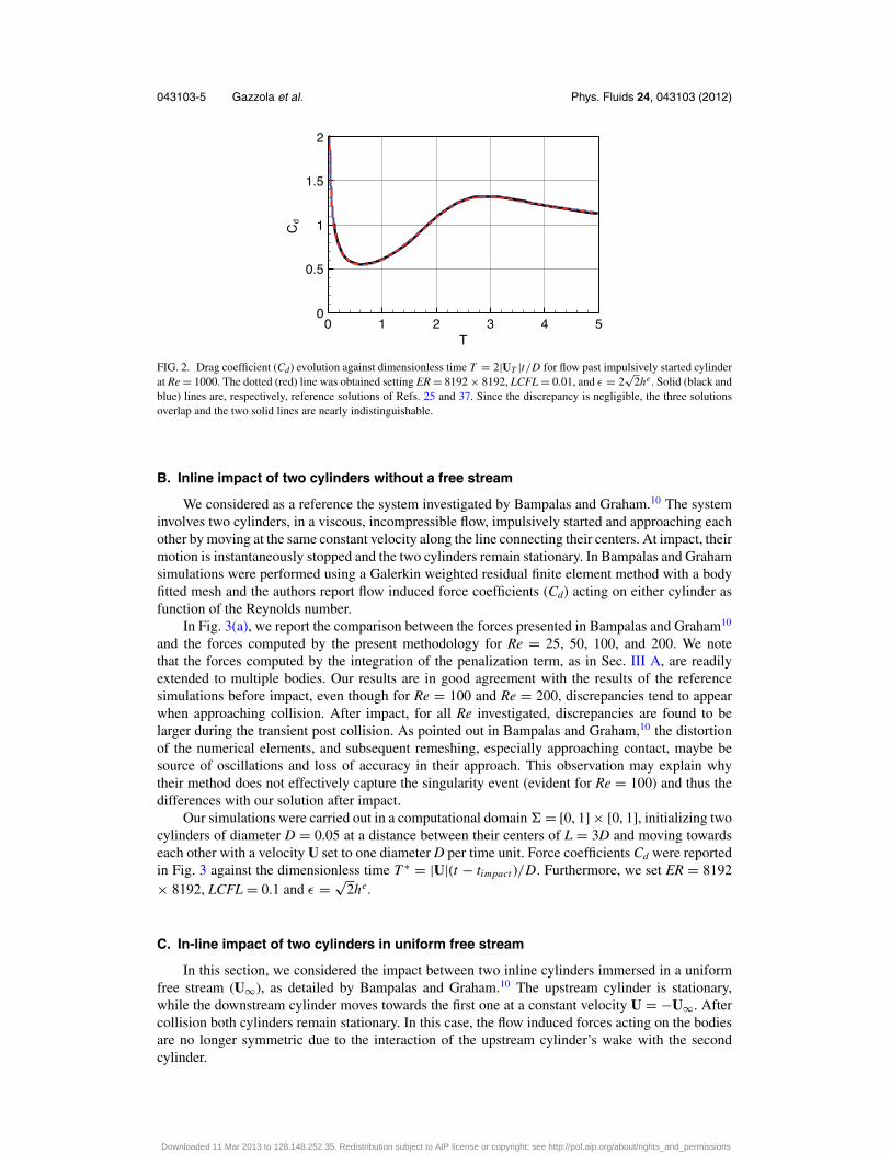
Flow past an impulsively started cylinder is a challenging problem for computational methodsdue to the singularity of the forces acting on the body at early times and the cascade of vorticalstructures emerging over time. In the domain � = [0, 1] × [0, 1], we considered a cylinder of diameterD = 0.05, initially located at (0.4, 0.5), moving at constant velocity UT = 0.1 (i.e., ut = UT , ur = 0),impulsively started in an incompressible, viscous flow at Re = |UT |D/ν = 1000. Furthermore, weset ER = 8192 × 8192, LCFL = 0.01 and ε = 2
√2he. As can be seen in Fig. 2, the drag coefficient
Cd = 2Fx/(|UT |D) computed here by integrating the penalization term F = − ∫�
χ (UT − u)dx,compares well with reference simulations and its evolution in time is accurately captured, with adiscrepancy found to be less than 1% at all times.25
Downloaded 11 Mar 2013 to 128.148.252.35. Redistribution subject to AIP license or copyright; see http://pof.aip.org/about/rights_and_permissions
043103-5 Gazzola et al. Phys. Fluids 24, 043103 (2012)
FIG. 2. Drag coefficient (Cd) evolution against dimensionless time T = 2|UT |t/D for flow past impulsively started cylinderat Re = 1000. The dotted (red) line was obtained setting ER = 8192 × 8192, LCFL = 0.01, and ε = 2
√2he . Solid (black and
blue) lines are, respectively, reference solutions of Refs. 25 and 37. Since the discrepancy is negligible, the three solutionsoverlap and the two solid lines are nearly indistinguishable.
B. Inline impact of two cylinders without a free stream
We considered as a reference the system investigated by Bampalas and Graham.10 The systeminvolves two cylinders, in a viscous, incompressible flow, impulsively started and approaching eachother by moving at the same constant velocity along the line connecting their centers. At impact, theirmotion is instantaneously stopped and the two cylinders remain stationary. In Bampalas and Grahamsimulations were performed using a Galerkin weighted residual finite element method with a bodyfitted mesh and the authors report flow induced force coefficients (Cd) acting on either cylinder asfunction of the Reynolds number.
In Fig. 3(a), we report the comparison between the forces presented in Bampalas and Graham10
and the forces computed by the present methodology for Re = 25, 50, 100, and 200. We notethat the forces computed by the integration of the penalization term, as in Sec. III A, are readilyextended to multiple bodies. Our results are in good agreement with the results of the referencesimulations before impact, even though for Re = 100 and Re = 200, discrepancies tend to appearwhen approaching collision. After impact, for all Re investigated, discrepancies are found to belarger during the transient post collision. As pointed out in Bampalas and Graham,10 the distortionof the numerical elements, and subsequent remeshing, especially approaching contact, maybe besource of oscillations and loss of accuracy in their approach. This observation may explain whytheir method does not effectively capture the singularity event (evident for Re = 100) and thus thedifferences with our solution after impact.
Our simulations were carried out in a computational domain � = [0, 1] × [0, 1], initializing twocylinders of diameter D = 0.05 at a distance between their centers of L = 3D and moving towardseach other with a velocity U set to one diameter D per time unit. Force coefficients Cd were reportedin Fig. 3 against the dimensionless time T ∗ = |U|(t − timpact )/D. Furthermore, we set ER = 8192× 8192, LCFL = 0.1 and ε = √
2he.
C. In-line impact of two cylinders in uniform free stream
In this section, we considered the impact between two inline cylinders immersed in a uniformfree stream (U∞), as detailed by Bampalas and Graham.10 The upstream cylinder is stationary,while the downstream cylinder moves towards the first one at a constant velocity U = −U∞. Aftercollision both cylinders remain stationary. In this case, the flow induced forces acting on the bodiesare no longer symmetric due to the interaction of the upstream cylinder’s wake with the secondcylinder.
Downloaded 11 Mar 2013 to 128.148.252.35. Redistribution subject to AIP license or copyright; see http://pof.aip.org/about/rights_and_permissions

043103-6 Gazzola et al. Phys. Fluids 24, 043103 (2012)
Re = 25
before impact after impact*
Re = 100
*before impact after impact
Re = 50
*before impact after impact
Re = 200
*before impact after impact
(a) (b)
(c) (d)
before impact ct* after impac * after impactbefore impact
(e)
FIG. 3. Inline impact of two cylinders without free stream. (a)–(d) Evolution of the force coefficient Cd against thedimensionless time T* for, respectively, Re = 25, 50, 100, and 200. Dotted (red) lines and symbols represent, respectively,the solutions of the present method and Bampalas and Graham.10 (e) Given from left to right and top to bottom is the timesequence of the vorticity field (−0.66 ≤ T* ≤ 2, �T* = 0.33).
We report a comparison of the measured force coefficients (Cd) at Re = 100 in Fig. 4(a). Forcompleteness we also report the evolution of net force coefficients after collision in Fig. 4(b), andcorresponding vorticity fields in Fig. 4(c). We note that force coefficients acting on the upstream anddownstream cylinders agree well with the reference solution.10
Simulations were performed in a computational domain � = [0, 1] × [0, 1], setting the freestream velocity U∞ to one diameter D per physical time unit and initializing the two cylinders ofdiameter D = 0.0125 at a distance of L = 15D between their centers. In Bampalas and Graham,10
the two cylinders were initialized closer to each other and their wakes were let to develop for anunspecified time, before impulsively starting the downstream cylinder. Here we opted for a startingcondition in which the downstream cylinder is impulsively started while initially located far enoughto ensure the development of the upstream wake. Force coefficients Cd are reported in Fig. 4 against
Downloaded 11 Mar 2013 to 128.148.252.35. Redistribution subject to AIP license or copyright; see http://pof.aip.org/about/rights_and_permissions

043103-7 Gazzola et al. Phys. Fluids 24, 043103 (2012)
* *
(b)(a)
* *
(c)
upstream
downstreamupstream
downstream
FIG. 4. Inline impact of two cylinders in uniform free stream. (a) and (b) Evolution of the force coefficient Cd against thedimensionless time T* at Re = 100 before (a) and after (b) collision. Circles and triangles correspond, respectively, to upstreamand downstream cylinders according to Bampalas and Graham.10 Dashed lines (red and blue) correspond, respectively, toupstream and downstream cylinders in the present computations. (c) From left to right and top to bottom, vorticity fields attimes T* = −13.3, −6.7, 0, 1.7, 3.3, 5, 6.7, 8.3, 10, 11.7, 18.3, 25.
the dimensionless time T ∗ = |U|(t − timpact )/D. Furthermore, we set the effective resolution of themultiresolution solver to ER = 16 384 × 16 384 with LCFL = 0.1 and ε = √
2he.
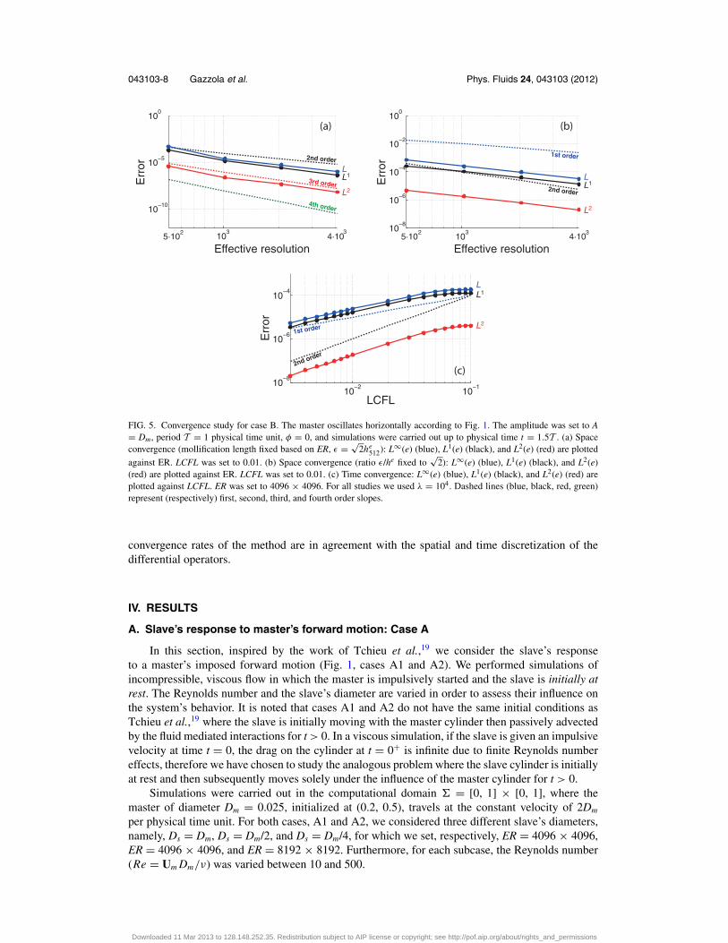
D. Convergence study
We performed a convergence study in space and time, for the test case B (Fig. 1). In thecomputational domain � = [0, 1] × [0, 1], we considered two equally sized cylinders (Dm = Ds
= 0.05), initially located at (0.4, 0.5) and (0.525, 0.5) and the Reynolds number Re = |Um |Dm/ν
= 100 (for further simulation details see Fig. 5 and Sec. IV B). Convergence orders were determinedby computing the L1, L2, and L∞ norm of the error e(t) =‖ xcm best resolved (t) − xcm(t) ‖, where xcm
is the slave’s center of mass location.Regarding space convergence, two different studies were performed by varying the effective
resolution ER between 512 × 512 and 4096 × 4096 with 16 384 × 16 384 as best resolved case,and setting LCFL = 0.01. In the first study, we fixed the model by setting the mollification lengthproportional to the coarsest effective grid spacing (ε = √
2he512). In the second study, the ratio ε/he is
chosen to be constant to investigate the convergence to the actual geometry. As we can see in Fig. 5,the method shows third order convergence (L1 = 3, L2 = 3, L∞ = 3) fixing ε = √
2he512 and between
first and second order (L1 = 1.4, L2 = 1.5, L∞ = 1.5) fixing ε/he = √2. Given the second order
smoothing function used in Ref. 21 for χ , we expect, for the fixed model case, a space convergenceorder lower than 4 but greater than 2, due to the compact limited support of the mollified region.
Time convergence study was performed setting ER = 4096 × 4096 and ε = √2he and varying
LCFL between 0.1 and 0.003 with 0.001 as best resolved case. The order of convergence was foundto be between first and second (L1 = 1.2, L2 = 1.74, L∞ = 1.2) (Fig. 5(c)). Time integration isperformed via Godunov splitting, entailing a mix of first and second order operators (second orderRunge-Kutta for Eqs. (16) and (17), implicit Euler for Eq. (14) and first order explicit Euler forEqs. (19) and (20)), thus we expect a convergence rate between one and two. We conclude that the
Downloaded 11 Mar 2013 to 128.148.252.35. Redistribution subject to AIP license or copyright; see http://pof.aip.org/about/rights_and_permissions
043103-8 Gazzola et al. Phys. Fluids 24, 043103 (2012)
10310
−8
10−6
10−4
10−2
100
103
10−10
10−5
100
10−2
10−110
−8
10−6
10−4
Err
or
LCFL
(a) (b)
(c)
4·103
4·103
5·102
5·102
Effective resolution Effective resolution
2nd order
3rd order
4th order
2nd order
1st order
1st order
2nd order
Err
or
Err
orL
L2
L1 L
L2
L1
L
L2
L1
FIG. 5. Convergence study for case B. The master oscillates horizontally according to Fig. 1. The amplitude was set to A= Dm, period T = 1 physical time unit, φ = 0, and simulations were carried out up to physical time t = 1.5T . (a) Spaceconvergence (mollification length fixed based on ER, ε = √
2he512): L∞(e) (blue), L1(e) (black), and L2(e) (red) are plotted
against ER. LCFL was set to 0.01. (b) Space convergence (ratio ε/he fixed to√
2): L∞(e) (blue), L1(e) (black), and L2(e)(red) are plotted against ER. LCFL was set to 0.01. (c) Time convergence: L∞(e) (blue), L1(e) (black), and L2(e) (red) areplotted against LCFL. ER was set to 4096 × 4096. For all studies we used λ = 104. Dashed lines (blue, black, red, green)represent (respectively) first, second, third, and fourth order slopes.
convergence rates of the method are in agreement with the spatial and time discretization of thedifferential operators.
IV. RESULTS
A. Slave’s response to master’s forward motion: Case A
In this section, inspired by the work of Tchieu et al.,19 we consider the slave’s responseto a master’s imposed forward motion (Fig. 1, cases A1 and A2). We performed simulations ofincompressible, viscous flow in which the master is impulsively started and the slave is initially atrest. The Reynolds number and the slave’s diameter are varied in order to assess their influence onthe system’s behavior. It is noted that cases A1 and A2 do not have the same initial conditions asTchieu et al.,19 where the slave is initially moving with the master cylinder then passively advectedby the fluid mediated interactions for t > 0. In a viscous simulation, if the slave is given an impulsivevelocity at time t = 0, the drag on the cylinder at t = 0+ is infinite due to finite Reynolds numbereffects, therefore we have chosen to study the analogous problem where the slave cylinder is initiallyat rest and then subsequently moves solely under the influence of the master cylinder for t > 0.
Simulations were carried out in the computational domain � = [0, 1] × [0, 1], where themaster of diameter Dm = 0.025, initialized at (0.2, 0.5), travels at the constant velocity of 2Dm
per physical time unit. For both cases, A1 and A2, we considered three different slave’s diameters,namely, Ds = Dm, Ds = Dm/2, and Ds = Dm/4, for which we set, respectively, ER = 4096 × 4096,ER = 4096 × 4096, and ER = 8192 × 8192. Furthermore, for each subcase, the Reynolds number(Re = Um Dm/ν) was varied between 10 and 500.
Downloaded 11 Mar 2013 to 128.148.252.35. Redistribution subject to AIP license or copyright; see http://pof.aip.org/about/rights_and_permissions
043103-9 Gazzola et al. Phys. Fluids 24, 043103 (2012)
Re=50
Re=100
Re=200
Re=500
Re=50
Re=100
Re=200
Re=500
Re=10
(b)
Re=10
(a)
s/D
m
Re=100Re=200
s/D
m
Re=50inviscidRe=500
inviscidRe=100Re=200Re=500
Re=50
Re=10
Re=10
(d)
(c)
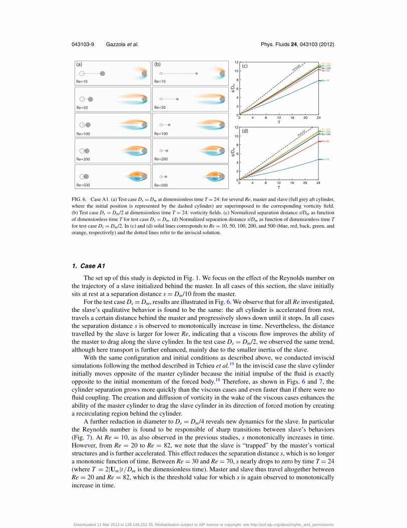
FIG. 6. Case A1. (a) Test case Ds = Dm at dimensionless time T = 24: for several Re, master and slave (full grey aft cylinder,where the initial position is represented by the dashed cylinder) are superimposed to the corresponding vorticity field.(b) Test case Ds = Dm/2 at dimensionless time T = 24: vorticity fields. (c) Normalized separation distance s/Dm as functionof dimensionless time T for test case Ds = Dm. (d) Normalized separation distance s/Dm as function of dimensionless time Tfor test case Ds = Dm/2. In (c) and (d) solid lines corresponds to Re = 10, 50, 100, 200, and 500 (blue, red, back, green, andorange, respectively) and the dotted lines refer to the inviscid solution.
1. Case A1
The set up of this study is depicted in Fig. 1. We focus on the effect of the Reynolds number onthe trajectory of a slave initialized behind the master. In all cases of this section, the slave initiallysits at rest at a separation distance s = Dm/10 from the master.
For the test case Ds = Dm, results are illustrated in Fig. 6. We observe that for all Re investigated,the slave’s qualitative behavior is found to be the same: the aft cylinder is accelerated from rest,travels a certain distance behind the master and progressively slows down until it stops. In all casesthe separation distance s is observed to monotonically increase in time. Nevertheless, the distancetravelled by the slave is larger for lower Re, indicating that a viscous flow improves the ability ofthe master to drag along the slave cylinder. In the test case Ds = Dm/2, we observed the same trend,although here transport is further enhanced, mainly due to the smaller inertia of the slave.
With the same configuration and initial conditions as described above, we conducted inviscidsimulations following the method described in Tchieu et al.19 In the inviscid case the slave cylinderinitially moves opposite of the master cylinder because the initial impulse of the fluid is exactlyopposite to the initial momentum of the forced body.18 Therefore, as shown in Figs. 6 and 7, thecylinder separation grows more quickly than the viscous cases and even faster than if there were nofluid coupling. The creation and diffusion of vorticity in the wake of the viscous cases enhances theability of the master cylinder to drag the slave cylinder in its direction of forced motion by creatinga recirculating region behind the cylinder.
A further reduction in diameter to Ds = Dm/4 reveals new dynamics for the slave. In particularthe Reynolds number is found to be responsible of sharp transitions between slave’s behaviors(Fig. 7). At Re = 10, as also observed in the previous studies, s monotonically increases in time.However, from Re = 20 to Re = 82, we note that the slave is “trapped” by the master’s vorticalstructures and is further accelerated. This effect reduces the separation distance s, which is no longera monotonic function of time. Between Re = 30 and Re = 70, s nearly drops to zero by time T = 24(where T = 2|Um |t/Dm is the dimensionless time). Master and slave thus travel altogether betweenRe = 20 and Re = 82, which is the threshold value for which s is again observed to monotonicallyincrease in time.
Downloaded 11 Mar 2013 to 128.148.252.35. Redistribution subject to AIP license or copyright; see http://pof.aip.org/about/rights_and_permissions

043103-10 Gazzola et al. Phys. Fluids 24, 043103 (2012)
(a)
Re=10
Re=20
Re=50
Re=82
Re=90
Re=500
(b)
(c)
s/D
ms/
Dm
inviscid
invi
scid
(see below for detail)
Re=500Re=200
Re=100
Re=90
Re=86
Re=84
Re=83
Re=82Re=10Re=81Re=80
Re=30Re=40
Re=82
Re=10
Re=81
Re=80
Re=20
Re=50
Re=70Re=60
FIG. 7. Case A1. (a) Test case Ds = Dm/4 at dimensionless time T = 24: for several Re, master and slave (full grey aftcylinder, where the initial position is represented by the dashed cylinder) are superimposed to the corresponding vorticityfield. (b) Normalized separation distance s/Dm as function of dimensionless time T. The Reynolds number is between 10 and500. Solid lines (of varying color) denote differing Reynolds numbers while the dotted line indicates the inviscid solution.(c) Enlargement of panel (b).
We note that we cannot exclude a similar behavior for Ds = Dm and Ds = Dm/2 at Re < 10, butwe could not investigate such scenarios due to the prohibitive computational costs since the time stepis constrained by high viscosity. It is also noted that in all simulations the wake of the slave cylinderis negligible and thus it can be safely assumed that response of the slave cylinder is dominated bythe wake produced from the master cylinder.
In order to study how the finite size of the slave cylinder’s affects the interaction, we comparethe slave cylinder’s motion with the advection of passive tracers without the presence of the slavecylinder. We consider Reynolds numbers Re = 50 and Re = 500 and place the respective tracers atlocations where the centers of the slave cylinders initially rest (i.e., for Ds/Dm = 1, 0.5, 0.25, x/Dm
= −1.1, − 0.85, − 0.725 with respect to the center of the master cylinder). The tracers are advectedusing a second-order Runge-Kutta scheme. As depicted in Fig. 8(a), for the cases correspondingto Ds/Dm = 0.5, 1, it is seen that distance traveled �x/Dm by the cylinder (dotted lines) is greater
0 4 8 12 16 20 240
5
10
15
mD
x /
T
D / D = 0.5
D / D =
0.25
D / D = 1
0 4 8 12 16 20 240
0.2
0.4
0.6
0.8
1
1.2
D / D = 0.25
D / D = 0.5 D / D = 1
mD
x /
T
(a) Re=50 (b) Re=500
FIG. 8. The distance traveled to the right by a slave cylinder of diameter Ds/Dm = 0.25, 0.5, 0.25 (dotted lines, black,blue, red, respectively) with s/Dm = 0.1 and a passive tracer (solid lines) initially located at the center of the slavecylinder for (a) Re = 50 and (b) Re = 500. The passive tracer is initially placed at a distance x/Dm = −1.1, − 0.85,− 0.725 (black, blue, red) with respect to the center of the master cylinder.
Downloaded 11 Mar 2013 to 128.148.252.35. Redistribution subject to AIP license or copyright; see http://pof.aip.org/about/rights_and_permissions

043103-11 Gazzola et al. Phys. Fluids 24, 043103 (2012)
than the distance traveled by the passive tracer. This suggests that the slave cylinder can be draggedfurther downstream than a passive tracer that is initialized at the same initial location. However, thepassive tracer travels slightly further to the right when it is placed at a location corresponding tothe case where the slave cylinder is Ds/Dm = 0.25. At Re = 500 (Fig. 8(b)), the slave cylinder isalways pulled further downstream than its passive tracer counterpart. It is also noted that in thesecases, at long times, the slave cylinder drifts to the right due to its inertia whereas the passive tracersdecelerate more quickly.
2. Case A2
In the potential flow simulations of Tchieu et al.,19 for configurations corresponding to case A2(see Fig. 1 for the setup), the slave was found, in some cases, to overtake the master, due to the largeside forces generated by the master. Here we tested an analogous case, where the slave cylinder isinitially at rest, in both viscous and inviscid environments. We specifically investigate the role of theReynolds number, as in case A1. Again, we clarify that the cases considered in Tchieu et al.19 havedifferent initial conditions than the viscous simulation for reasons mentioned in Sec. IV A 1. In allcases of this section, the slave initially is placed at a separation distance s = Dm/5 from the master(Fig. 1).
For the test cases Ds = Dm and Ds = Dm/2, results are illustrated in Fig. 9. As can be noticed, forall Re investigated, the slave’s qualitative behavior is the same: the aft cylinder is accelerated fromrest, it experiences a side force which moves the cylinder into the wake, then drafts in the master’swake, travels a certain distance behind the master and progressively slows down until it stops. In allcases the separation distance in the horizontal direction sx is observed to monotonically increase intime. Consistently with case A1, a viscous flow is shown to improve the ability of the master to dragalong the slave cylinder. Moreover, in the inviscid case where the slave cylinder is at rest, the sametrend occurs. The side force generated in the low pressure region between the two cylinders pulls theslave cylinder behind the master and then the slave stops. As seen in Figs. 9(c) and 9(d), the inviscidcase gives the maximum separation and is pulled only very slightly in the positive x–direction.
As already observed in case A1, a further diameter reduction to Ds = Dm/4, reveals the existenceof two threshold Reynolds numbers, corresponding to transitions to different qualitative behaviors(see Fig. 10). In particular, for Re < 30, the horizontal separation distance sx monotonically increasesin time, for 30 ≤ Re ≤ 49 the slave is further accelerated and the separation sx nearly drops to zero
Re=30
Re=50
Re=100
Re=500
Re=10 Re=10
Re=50
Re=100
Re=500
Re=30
(b)(a) (c)
(d)
s /
Ds
/D
FIG. 9. Case A2. (a) Test case Ds = Dm at dimensionless time T = 32 for several Re. Master (initial position is representedby the orange dashed cylinder) and slave (full grey aft cylinder, where the initial position is represented by the black dashedcylinder) are superimposed to the corresponding vorticity field. (b) Test case Ds = Dm/2 at dimensionless time T = 32:vorticity fields. (c) Normalized separation distance in the horizontal direction s/Dm as function of dimensionless time T fortest case Ds = Dm. (d) Normalized separation distance in the horizontal direction s/Dm as function of dimensionless time Tfor test case Ds = Dm/2. In (c) and (d) solid (blue, green, red, black, and orange) lines correspond to Re = 10, 30, 50, 100,and 500 whereas the dashed line corresponds to the inviscid case.
Downloaded 11 Mar 2013 to 128.148.252.35. Redistribution subject to AIP license or copyright; see http://pof.aip.org/about/rights_and_permissions

043103-12 Gazzola et al. Phys. Fluids 24, 043103 (2012)
Re=20
Re=32
Re=42
Re=49
Re=50
Re=500
(b)
(c)
(a)inviscid
invi
scid
Re=500
Re=100
Re=70
Re=60
Re=55Re=10
Re=20
Re=50
Re=30
see belowfor detail
Re=20
Re=32Re=33Re=36Re=49Re=38Re=42
s /
mx
Ds
/m
xD
FIG. 10. Case A2. (a) Test case Ds = Dm/4 at dimensionless time T = 32 for several Re. The master (initial position isrepresented by the orange dashed cylinder) and slave (full grey aft cylinder, where the initial position is represented by theblack dashed cylinder) cylinders are superimposed to the corresponding vorticity field. (b) Normalized separation distancein the horizontal direction sx/Dm as function of dimensionless time T. Solid lines correspond to Reynolds number rangingbetween 10 and 500. Dashed line corresponds to the inviscid case. (c) Enlargement of panel (b).
and finally for Re > 49, sx is again observed to increase in time. Varying the initial master-slavedistance, we always observed either a monotonically increase of sx or sudden accelerations as inthe last case. We mention that similar behavior may occur for Ds = Dm and Ds = Dm/2 for Re <
10, but we could not investigate such scenarios due to the prohibitive computational costs related todiffusion constraints.
It is concluded that the phenomena illustrated using the method defined in Tchieu et al.19
cannot qualitatively reproduce the effects discovered when the slave cylinder is initially at rest ina viscous environment. More specifically the induced motion in the inviscid case is minimal whileviscosity effects increase the fluid-mediated response of the slave cylinder. With increasing viscosity,it appears that bodies smaller than the master cylinder can experience a free ride from rest by sittingin the wake of the master cylinder. This may have interesting implications of viscous transport ofmaterial via biogenic ocean mixing as discussed in Katija and Dabiri43 and Dabiri.44 At most, theinviscid solutions only provide a lower limit of interaction when the slave body is initially at rest.
As with configuration A1, to assess how the finite size of the slave cylinder affects the fluid-mediated interactions, we plot the paths of passive tracers for Re = 50 and 500 in Fig. 11. The passivetracers are initially located at y/Dm = 1.2, 0.95, 0.825 with respect to the master cylinder (correspond-ing to simulations in case A2 with Ds/Dm = 1.0, 0.5, 0.25). The distance traveled is compared inFig. 12. Note the similarities in path initially taken by both the passive tracer and the respective slavecylinder. The passive tracer and the cylinder both initially travel in the negative x–direction beforegoing in the positive direction. For Re = 50, the passive tracers exhibit the same qualitative behaviordescribed in case A1. At Ds/Dm = 0.25 the passive tracer is pulled further to the right than the slavecylinder. At Ds/Dm = 0.5 and 1 the slave cylinder moves further downstream than the passive tracer,but the differences are slight. For Re = 500 (Fig. 12(b)), we see that the slave cylinders drift to theright at a higher velocity than the passive tracers as in case A1.
Downloaded 11 Mar 2013 to 128.148.252.35. Redistribution subject to AIP license or copyright; see http://pof.aip.org/about/rights_and_permissions

043103-13 Gazzola et al. Phys. Fluids 24, 043103 (2012)
(a) Re=50
(b) Re=500
FIG. 11. The advection of a passive tracer up to T = 32 initialized above the forced cylinder for (a) Re = 50 and (b) Re= 500. The passive tracer is initially placed at a distance y/Dm = 1.2, 0.95, 0.825 corresponding to the center of the slavecylinders for cases Ds/Dm = 0.25, 0.5, 0.25 (dotted line, black, blue, red, respectively) with s/Dm = 0.2. Grey dots indicatethe starting and ending positions of the tracers. Vorticity field is given for reference.
We note that additional simulations where the slave cylinder was placed at oblique anglestrailing the master cylinder were performed and no significant differences were observed betweenthese cases and those presented in Sec. IV A, thus these results are omitted for brevity.
B. Slave’s response to master’s horizontal oscillation: Case B
In this section, inspired by the work of Nair and Kanso18 in potential flow (also see Lamb45
and Borisov et al.46), we considered the slave’s response when the master is forced to oscillatehorizontally (Fig. 1, case B). We performed simulations of incompressible, viscous flows in whichthe master is impulsively started and the slave is initially at rest. All simulations were carried out inthe computational domain � = [0, 1] × [0, 1], in which the master of diameter Dm = 0.05, initiallylocated at (0.4, 0.5), oscillates horizontally according to xm = A sin(2π t/T + φ), where xm is itscenter of mass and A, T , and φ, respectively, oscillation amplitude, period and phase. In all casesER = 2048 × 2048 and T = 1 physical time unit.
As for case A1 and A2, we focused on the effect of the Reynolds number (10 ≤ Re ≤ 100) on thesystem’s dynamics. Here the characteristic velocity was defined as |Um | = |2π A/T | and thereforeRe = 2π ADm/(νT ). Furthermore, the systems investigated were characterized by A = Dm, initialseparation distance 2Dm ≤ d ≤ 5Dm, initial slave’s location (0.4 + d, 0.5) and diameter 0.1Dm ≤ Ds
≤ 1.25Dm.In Fig. 13(a), we report the slave’s normalized displacement (�x/Dm, positive and negative �x,
correspond, respectively, to repulsion and attraction by the master), versus the dimensionless timeT = 4π At/(T Dm), for the system characterized by Ds = Dm, d = 2.5Dm and φ = 0. Similar tocases A1 and A2, we observe a change in qualitative behavior as a function of the Reynolds number.In fact, when Re > 27, the slave is repelled by the master as observed in Fig. 13(c), while for
(a) Re=50
0 8 16 24 32−5
0
5
10
15
20
D / D = 1
D / D = 0.5
D / D = 0.25
mD
x /
T
(b) Re=500
0 8 16 24 32−0.2
0
0.2
0.4
0.6D / D = 0.25
D / D = 0.5
D / D = 1
mD
x /
T
FIG. 12. The distance traveled to the right by a slave cylinder of diameter Ds/Dm = 0.25, 0.5, 0.25 (dotted line, black,blue, red, respectively) with s/Dm = 0.2 and a passive tracer (solid line) initially located at the position corresponding tothe center of the slave cylinder for (a) Re = 50 and (b) Re = 500. The passive tracer is initially placed at a distance y/Dm
= 1.2, 0.95, 0.825 (black, blue, red) with respect to the center of the master cylinder. Note that oscillatory vortex shedding isnot visible in (b) as compared to Fig. 11 because the flow remains symmetric.
Downloaded 11 Mar 2013 to 128.148.252.35. Redistribution subject to AIP license or copyright; see http://pof.aip.org/about/rights_and_permissions

043103-14 Gazzola et al. Phys. Fluids 24, 043103 (2012)
Re=27Re=30
Re=25
Re=20
Re=15
Re=40Re=50Re=60Re=80Re=100
ππ π π π πT
Δx/
Dm
d/Dm
D /Dms
Thr
esho
ld R
e
Re=80
Re=27
Re=20
T=3.20π T=8.28π T=13.60π T=24.0π
(a) (b)
(c)
(d)
(e)
FIG. 13. Case B. (a) Slave’s normalized displacement (�x/Dm) versus dimensionless time T, for several Reynolds numbers(from top to bottom Re = 100, 80, 60, 50, 40, 30, 27, 25, 20, 15) and φ = 0, A = Dm, Ds = Dm, d = 2.5Dm. (b) ThresholdReynolds number (Reth) as function of Ds/Dm and d/Dm. (c)–(e) Evolution in time of the vorticity fields for the casesRe = 80, 27, and 20 reported in panel (a). The dashed cylinder represents the initial slave’s location.
Re < 27, the slave is attracted as observed in Fig. 13(e). The threshold value of Reth 27,corresponds to the slave oscillating around its initial position (Fig. 13(d)). The vorticity plots,Figs. 13(c)–13(e), reveal that for Re > 27, the flow develops a secondary structure constituted by atop and bottom patch of, respectively, positive and negative vorticity. Such structure, inducing a flowto the right of the master, contributes to the repulsion of the slave. On the other hand, an increase inviscosity, is responsible for a quick dissipation of this structure, favoring the attraction of the slaveby the master.
As mentioned above, the same study was carried out for several configurations where bothd/Dm and Ds/Dm where varied, in order to assess the impact of these parameters on the system.All simulations presented the same trend as the one above described and the threshold Reynolds
A=0.25D
A=0.5D A=1.50D
A=1.0D m
(b)A=1.50D
A=1.0D
A=0.5D
A=0.25D
(a)
FIG. 14. Case B. Vorticity fields at physical time t = 6, corresponding to oscillation amplitudes A = 1.5Dm, A = 1Dm,A = 0.5Dm, A = 0.25Dm, and φ = 0. The dashed cylinder represents the initial slave’s location. (b) Slave’s normalizeddisplacement (�x/Dm) versus physical time t for A = 1.5Dm (blue), A = 1Dm (green), A = 0.5Dm (red), A = 0.25Dm (black).Solid and dashed lines correspond, respectively, to φ = 0 and φ = π .
Downloaded 11 Mar 2013 to 128.148.252.35. Redistribution subject to AIP license or copyright; see http://pof.aip.org/about/rights_and_permissions

043103-15 Gazzola et al. Phys. Fluids 24, 043103 (2012)
Re = 500, A=1.0Dmimpinging vortex pairs
master slave
FIG. 15. Vorticity field at physical time t = 6, with oscillation amplitude A = Dm, Re = 500, and φ = 0. The slave cylinderon the right is free to move. Shades are over saturated to clearly show how the vortex pair created from the motion of themaster cylinder impinges on the slave cylinder, imparting it with positive x −momentum.
numbers identified, given the pairs (d/Dm − Ds/Dm) are reported in Fig. 13(b). The initial separationdistance d/Dm strongly influences Reth causing its exponential decay. On the other hand, the diameterratio Ds/Dm, does not substantially affect Reth, revealing that the flow features play a more importantrole than the inertia of the slave.
We note that in the study of Nair and Kanso,18 a change in the system’s qualitative behaviorwas achieved by switching the oscillation phase from φ = π (repulsion) to φ = 0 (attraction).In a viscous environment this behavior is not observed and to an out-of-phase oscillation simplycorresponds an out-of-phase slave’s displacement curve, without causing any change in qualita-tive behavior, whether repulsive or attractive. For clarity we did not report out-of-phase curves inFig. 13(a), nevertheless, as an example, slave’s displacement curves are depicted in Fig. 14(b)for Re = 100. In such simulations the oscillation amplitude was set between 0.25Dm ≤ A≤ 1.5Dm and the slave was initialized at (0.4 + 1.5Dm + A, 0.5). As can be noticed the largerthe amplitude A, the stronger the repulsion of the slave from the master, but switching phase didnot affect the slave’s drifting direction. It is observed, even initially in the first period, that theviscous and inviscid case are qualitatively different. For example, in the inviscid case, for sinusoidalforcing with φ = 0 (φ = π ), it has been shown that the slave cylinder is initially attracted to (re-pelled by) the master cylinder.18 In all viscous cases, both the master and slave cylinder oscillatein phase. In a more global sense, the long time behavior is also different. In inviscid cases whereφ = 0, the slave cylinder is initially attracted and then repelled given large initial separation dis-tances or attracted to the point of collision with the master cylinder for shorter initial separationdistances.18, 46 In viscous simulations, the creation of a vortex dipole (see Fig. 15) that impingeson the slave cylinder at every cycle transports momentum from the fluid to the slave cylinderallowing it to more effectively move away from the oscillating cylinder. This mechanism is notpresent when Re < 27 where the dipoles are less intense and drastically diffuse before reachingthe slave cylinder. The transfer of momentum is exacerbated by both the increase in oscillationamplitude and Reynolds number where the transport momentum becomes more highly correlatedwith the imposed x–motion of the master cylinder. We show a simulation at Re = 500 to demon-strate the creation of successive dipoles and the subsequent impingement on the slave cylinder(Fig. 15).
We note that passive tracers were also introduced in the flow for comparison. The paths of thetracers were found to be qualitatively the same as the slave cylinder, e.g., attracted to the cylinderwhen Re = 20 and repelled when Re = 80.
V. CONCLUSIONS
We considered the dynamics of two interacting moving cylinders immersed in a two-dimensionalviscous, incompressible flow. The simulations are performed via a wavelet adapted, multi resolution,remeshed vortex method coupled with Brinkman penalization and projection approach. The presentviscous studies have been motivated by related potential flow simulations of slave-master cylinderinteractions18, 19 and are aimed to assess the role of finite Reynolds numbers in these situations.
Downloaded 11 Mar 2013 to 128.148.252.35. Redistribution subject to AIP license or copyright; see http://pof.aip.org/about/rights_and_permissions

043103-16 Gazzola et al. Phys. Fluids 24, 043103 (2012)
The method is validated on the problem of two interacting cylinders, computing the forcesexperienced by both solids. Results were found to be in good agreement with reference simulationsand an error analysis of the method is presented to assess its convergence in space and time.
Two flow mediated problems were considered, involving a master cylinder forced to moveforward (cases A1 and A2) and to oscillate horizontally (case B) and a slave cylinder free to respond.In both cases the qualitative response of the system was found to depend on the Reynolds number,responsible for sharp transitions between different regimes. In case A1 and A2, the Reynolds numberis responsible for sudden accelerations of the slave, while, in case B, it dictates whether the slave isrepelled or attracted by the master. In some instances of cases A1 and A2, it is even possible that theslave cylinder is pulled further downstream by the master cylinder than if the slave cylinder werereplaced by a passive particle. Thus, in specific cases, a finite size particle may be transported moreeffectively through fluid-mediated interactions than even passive tracers.
We conclude by demonstrating that there can be drastic differences in the behavior of inter-acting bodies as simulated by potential flow simulations and by viscous simulations at finite andmoderate Reynolds numbers. It is worth mentioning that at these moderate Reynolds numbers, three-dimensional instabilities may occur (e.g., for the circular cylinder, the onset of instability occurs atRe ≈ 200, see Ref. 47). Simulations in three dimensions are, at the moment, prohibitively costly (theadded dimensionality makes simulations orders of magnitude more expensive) and thus we havepresented a two-dimensional analog here in hopes of elucidating fundamental Reynolds numbereffects on the fluid-mediated interactions. Future work will focus on extending the Reynolds numberregime of the present studies and adding capabilities to simulate self-propelled, three-dimensionalswimmers.
ACKNOWLEDGMENTS
We wish to thank Manfred Quack and Diego Rossinelli for their support on MRAG and BabakHejazialhosseini for his deep discussions.
1 D. Weihs, “Hydromechanics of fish schooling,” Nature (London) 241(5387), 290–291 (1973).2 J. C. Liao, D. N. Beal, G. V. Lauder, and M. S. Triantafyllou, “Fish exploiting vortices decrease muscle activity,” Science
302(5650), 1566–1569 (2003).3 D. Weihs, “The hydrodynamics of dolphin drafting,” J. Biol. 3(2), 8 (2004), see online at http://jbiol.com/content/3/2/8.4 V. Gyrya, I. S. Aranson, L. V. Berlyand, and D. Karpeev, “A model of hydrodynamic interaction between swimming
bacteria,” Bull. Math. Biol. 72(1), 148–183 (2010).5 T. Ishikawa, M. P. Simmonds, and T. J. Pedley, “Hydrodynamic interaction of two swimming model micro-organisms,”
J. Fluid Mech. 568, 119–160 (2006).6 D. L. Koch and G. Subramanian, “Collective hydrodynamics of swimming microorganisms: Living fluids,” Annu. Rev.
Fluid Mech. 43, 637–659 (2011).7 B. Metzger, M. Nicolas, and E. Guazzelli, “Falling clouds of particles in viscous fluids,” J. Fluid Mech. 580, 283–301
(2007).8 M. Nicolas, “Experimental study of gravity-driven dense suspension jets,” Phys. Fluids 14(10), 3570–3576 (2002).9 G. A. Voth, B. Bigger, M. R. Buckley, W. Losert, M. P. Brenner, H. A. Stone, and J. P. Gollub, “Ordered clusters and
dynamical states of particles in a vibrated fluid,” Phys. Rev. Lett. 88(23), 234301 (2002).10 N. Bampalas and J. M. R. Graham, “Flow-induced forces arising during the impact of two circular cylinders,” J. Fluid
Mech. 616, 205–234 (2008).11 J. A. Riffell and R. K. Zimmer, “Sex and flow: the consequences of fluid shear for sperm-egg interactions,” J. Exp. Biol.
210(20), 3644–3660 (2007).12 B. Basso, J. Love, and J. K. Hedrick, “Airborne, autonomous and collaborative,” Mech. Eng. (Am. Soc. Mech. Eng.)
133(4), 26–32 (2011).13 H. Park, F. Noca, and P. Koumoutsakos, “Vortobots: vortex-generating microscopic robots would move in swarms,” NASA
Tech Briefs, Control No. NP0-21188, NASA’s Jet Propulsion Laboratory, 2005.14 J. F. Brady and G. Bossis, “Stokesian dynamics,” Annu. Rev. Fluid Mech. 20, 111–157 (1988).15 S. T. Kim, Y. O. Fuentes, and S. J. Karrila, “Towards as initio simulations of concentrated suspensions,” J. Stat. Phys.
62(5-6), 1197–1223 (1991).16 M. Sebastien and E. Lauga, “The long-time dynamics of two hydrodynamically-coupled swimming cells,”
Bull. Math. Biol. 72(4), 973–1005 (2010).17 G. Subramanian and D. L. Koch, “Evolution of clusters of sedimenting low-Reynolds-number particles with Oseen
interactions,” J. Fluid Mech. 603, 63–100 (2008).18 S. Nair and E. Kanso, “Hydrodynamically coupled rigid bodies,” J. Fluid Mech. 592, 393–411 (2007).19 A. A. Tchieu, D. Crowdy, and A. Leonard, “Fluid-structure interaction of two bodies in an inviscid fluid,” Phys. Fluids
22(10), 107101 (2010).
Downloaded 11 Mar 2013 to 128.148.252.35. Redistribution subject to AIP license or copyright; see http://pof.aip.org/about/rights_and_permissions

043103-17 Gazzola et al. Phys. Fluids 24, 043103 (2012)
20 R. Glowinski, T. W. Pan, T. I. Hesla, D. D. Joseph, and J. Periaux, “A fictitious domain approach to the direct numericalsimulation of incompressible viscous flow past moving rigid bodies: Application to particulate flow,” J. Comput. Phys.169(2), 363–426 (2001).
21 M. Gazzola, P. Chatelain, W. M. van Rees, and P. Koumoutsakos, “Simulations of single and multiple swim-mers with non-divergence free deforming geometries,” J. Comput. Phys. 230(19), 7093–7114 (2011), see online athttp://www.sciencedirect.com/science/article/pii/S0021999111002737.
22 J. Eldredge, “A reconciliation of viscous and inviscid approaches to computing locomotion of deforming bodies,”Exp. Mech. 50, 1349–1353 (2010).
23 H. Fukuda, S. Torisawa, Y. Sawada, and T. Takagi, “Ontogenetic changes in schooling behaviour during larval and earlyjuvenile stages of pacific bluefin tuna thunnus orientalis,” J. Fish Biol. 76(7), 1841–1847 (2010).
24 M. E. Huntley and M. Zhou, “Influence of animals on turbulence in the sea,” Mar. Ecol.: Prog. Ser. 273, 65–79 (2004).25 P. Koumoutsakos and A. Leonard, “High-resolution simulations of the flow around an impulsively started cylinder using
vortex methods,” J. Fluid Mech. 296, 1–38 (1995).26 G. H. Cottet and P. Poncet, “Advances in direct numerical simulations of 3d wall-bounded flows by vortex-in-cell methods,”
J. Comput. Phys. 193(1), 136–158 (2004).27 M. Bergdorf and P. Koumoutsakos, “A lagrangian particle-wavelet method,” Multiscale Model. Simul. 5(3), 980–995
(2006).28 O. V. Vasilyev and N. K. R. Kevlahan, “Hybrid wavelet collocation-Brinkman penalization method for complex geometry
flows,” Int. J. Numer. Methods Fluids 40(3-4), 531–538 (2002).29 M. Coquerelle and G. H. Cottet, “A vortex level set method for the two-way coupling of an incompressible fluid with
colliding rigid bodies,” J. Comput. Phys. 227(21), 9121–9137 (2008).30 B. Hejazialhosseini, D. Rossinelli, M. Bergdorf, and P. Koumoutsakos, “High order finite volume methods on wavelet-
adapted grids with local time-stepping on multicore architectures for the simulation of shock-bubble interactions,”J. Comput. Phys. 229(22), 8364–8383 (2010).
31 D. Rossinelli, B. Hejazialhosseini, M. Bergdorf, and P. Koumoutsakos, “Wavelet-adaptive solvers on multi-core architec-tures for the simulation of complex systems,” Concurrency Comput.: Pract. Exper. 23(2), 172–186 (2011).
32 D. Rossinelli, B. Hejazialhosseini, D. G. Spampinato, and P. Koumoutsakos, “Multicore/multi-gpu accelerated simulationsof multiphase compressible flows using wavelet adapted grids,” SIAM J. Sci. Comput. (USA) 33(2), 512–540 (2011).
33 P. Ploumhans and G. S. Winckelmans, “Vortex methods for high-resolution simulations of viscous flow past bluff bodiesof general geometry,” J. Comput. Phys. 165(2), 354–406 (2000).
34 G. H. Cottet and P. Koumoutsakos, Vortex Methods, Theory and Practice (Cambridge University Press, Cambridge,England, 2000).
35 E. Arquis and J. P. Caltagirone, “On the hydrodynamical boundary-conditions along a fluid layer porous-medium interface -application to the case of free convection,” C. R. Acad. Sci., Ser. II: Mec., Phys., Chim., Sci. Terre Univers 299(1), 1–4(1984).
36 P. Angot, C. H. Bruneau, and P. Fabrie, “A penalization method to take into account obstacles in incompressible viscousflows,” Numer. Math. 81(4), 497–520 (1999).
37 D. Rossinelli, M. Bergdorf, G. H. Cottet, and P. Koumoutsakos, “Gpu accelerated simulations of bluffbody flows using vortex particle methods,” J. Comput. Phys. 229(9), 3316–3333 (2010), see online athttp://www.sciencedirect.com/science/article/B6WHY-4Y6J428-2/2/0ddb10a20cfce335ebaf14d221dabc46.
38 N. A. Patankar and N. Sharma, “A fast projection scheme for the direct numerical simulation of rigid particulate flows,”Commun. Numer. Methods Eng. 21(8), 419–432 (2005).
39 J. Barnes and P. Hut, “A hierarchical o(n-log-n) force-calculation algorithm,” Nature (London) 324(6096), 446–449 (1986).40 L. Greengard and V. Rokhlin, “A fast algorithm for particle simulations,” J. Comput. Phys. 73(2), 325–348 (1987).41 D. Rossinelli, “Multiresolution flow simulations on multi/many-core architectures,” Ph.D. dissertation (ETH Zurich, 2011).42 P. Koumoutsakos, “Multiscale flow simulations using particles,” Annu. Rev. Fluid Mech. 37, 457–487 (2005).43 K. Katija and J. O. Dabiri, “A viscosity-enhanced mechanism for biogenic ocean mixing,” Nature (London) 460(7255),
624–627 (2009).44 John O. Dabiri, “Role of vertical migration in biogenic ocean mixing,” Geophys. Res. Lett. 37, L11602,
doi:10.1029/2010GL043556 (2010).45 H. Lamb, Hydrodynamics (Dover, New York, 1945).46 A. V. Borisov, I. S. Mamaev, and S. M. Ramodanov, “Dynamics of two interacting circular cylinders in perfect fluid,”
Discrete Contin. Dyn. Syst. 19(2), 235–253 (2007).47 C. H. K. Williamson, “Three-dimensional wake transition,” J. Fluid Mech. 328, 345–407 (1996).
Downloaded 11 Mar 2013 to 128.148.252.35. Redistribution subject to AIP license or copyright; see http://pof.aip.org/about/rights_and_permissions