Embed Size (px)
Citation preview

1
HYDAIRAHydrau l i c Cy l i nde rs
www.specken-drumag.comwww.ribapneumatic.dewww.hydaira.chwww.cges.be

IntroductionEffective round basic design. Compact construction with space-saving outside diameter and length for an excellent ratio between power and space requirements. The screw connections on all components ensure simple installation and replacement.
Maximum pressureThe pressures stated in the catalog refer to the dynamic continuous pressure for all mounting types. A higher pressure is also permissible in some cases, depending on the application and installation situation. A written description of your application is mandatory for approval of this higher pressure. If outlet throttling is employed, the resulting pressure ratio must be taken into account. The dynamic pressure in the cylinder should only exceed the maximum operating pressure by 30% for a short time.
Minimum pressureThe minimum permissible pressure depends on the employed sealing type. Please contact us to discuss the selection of the required seals for pressures of below 10 bar.
Cylinder mountingIf a different mounting method than the standard method is required, we would be pleased to investigate solutions to suit your needs.
Function typesVarious functional cylinder types are available. Customized solutions are available upon request.
ConnectionsWith Whitworth pipe thread; the length of the connections can be modi-fied upon request. Larger and other (metric) connections are available upon request.
Piston rodThe standard material for piston rods is CK 45, ground and hard-chrome plated. Hardened and stainless steel piston rods are also available. Piston rods with special coatings can be supplied upon request. Thicker or thinner piston rods are generally possible. The piston rods should, however, always be tested for bend resistance.
Piston rod endThe end of the piston rod is manufactured as a standard version described in the catalogue if not otherwise specified by the cus-tomer. Variations from the catalogue versions are possible when the required dimensions are specified.
Cylinder tubeThe cylinder tube is made of steel and the liner is very finely honed.
SealsWe supply up to 8 different seal types, depending on the speed, temperature and pressure. Should other sealing types or materials be required, we would be pleased to select the right seals for your application.
End position dampingThe purpose of end position damping is to lower the kinetic energy to a level at which neither the cylinder nor the machine in which the cylinder is installed is damaged without having to install a corresponding extra device. We recommend a damping feature for speeds exceeding 20 mm/s. Various damping systems are used depending on the cylinder type. These include plastic impact damping, self-adjusting progressive damping or adjustable damp-ing with needle valves. Depending on the application we can also offer optimized damping (shorter damping times).
2
Information and General Notes

ZHSS Series 32-33Piston diameters 16-50 mm, operating pressures up to 400 bar, round, compact design, 3 types of fastening
ZU 250 series 24-30Piston diameters 20-100 mm, operating pressures up to 250 bar, 4 seal versions, 11 types of fastening
ZISO/T series acc. to ISO 6020/1 17-23Piston diameters 25-100 mm, operating pressures up to 160 bar, 4 seal versions, 11 types of fastening
ZU series 10-16Piston diameters 10-100 mm, operating pressures up to 100 bar, 8 seal versions, 12 types of fastening
ZAR series 4-9 Piston diameters 10-25 mm, operating pressures up to 63 bar, 6 seal versions, 6 types of fastening, stainless
Page
3
Accessories – Piston rod knuckles 34Joint head GS – Fork joint GG – Swivel head GE
Piston force and Bend resistance 35Determination of cylinder and piston rod diameters
80
60
40
20
5
10,0 1,
0 1 5 6 7 8 9 01Special versions 31Hydraulic cylinders with piston Ø100-250 mm Hydraulic cylinders with end position sensingHydraulic cylinders in servo quality Hydraulic cylinders with path-measuring system
Table of Contents

63 bar standard cylinderDimensions acc. to ISO 6432Piston Ø 10-25 mmLengths of stroke at your option (take account of the bend resistance, see page 35)Standard lengths of stroke
Robust - stainless - antimagnetic Nylon impact absorption Turnable connections
Determine your 63 bar standard cylinder
Ordering example: ZAR-FBv 25/125 NHR15 D-U01 E31
Cylinder type
å Mounting type
ç Piston Ø
é Length of strokeStandard stroke series NHR
è Function type
ê Seal type
ë OptionsEnd of piston rod
Connections Vent screws
Special versions on request
4
ZAR series

General information
å Mounting types
é Length of stroke
Design:Guide head and cover: brassPiston rod: stainless steel (1.4305), polishedPiston: light alloyCylinder tube: stainless steel tube (1.4301), bore very fi nely honed
5
Basic version Front flange Front angle foot (for short strokes)
Bearing block Rear flange Two angle feet
Lengths of stroke at your option: We manufacture any length of stroke you desire.Standard stroke versions NHR: A choice of 8 standard lengths of stroke for every piston Ø is available for short-time delivery.l Ordering example: ZAR-FBv 20/100 NHR14 D-U00
Piston Ø 10 12 16 20 25 Intermediate strokes aNHR:By inserting a stroke-limiting bushing(LA) any intermediate stroke (ZH) can be realized.The measures of length L1 and L1c always correspond with the normal stroke.l Ordering example: ZAR-FBv 20/90 aNHR14 D-U00
Function Stroke NHRNHR measures of length
L1 L1c L1 L1c L1 L1c L1 L1c L1 L1c
D
25 11 67 89 69 100 76 107 84 120 89 12950 12 92 114 94 125 101 132 109 145 114 15480 13 122 144 124 155 131 162 139 175 144 184100 14 142 164 144 175 151 182 159 195 164 204125 15 167 189 169 200 176 207 184 220 189 229160 16 202 224 204 235 211 242 219 255 224 264200 17 242 264 244 275 251 282 259 295 264 304250 18 292 314 294 325 301 332 309 345 314 354
ç Piston ØPiston Ø (mm) 10 12 16 20 25Piston surface pushing (cm²) 0.78 1.13 2.00 3.14 4.90Piston surface pulling (cm²) 0.66 0.85 1.72 2.64 4.12

6
Standard version: U00 for hydraulic fl uid (mineral oil). Seal types for other pressure media on request.
Seal types U00 U01* U06 U07 U11 U12Piston seal, PTFE gliding ring (min. piston Ø 20 mm with driving band) l l l l l lRod seal, grooved ring l lRod seal, PTFE gliding ring (min. piston Ø 20 mm) l l l lDust seal l l lO-rings Nitril l l l lO-rings Viton l l
Piston speedmax. 0.5 m/s l lmax. 10 m/s l l l l
Temperature range-20/+100 °C l l l l-20/+200 °C l l
*bbb
End of piston rod: Standard version: E16 Additional versions as shown in the illustrations are manufactured based on the catalog if not otherwise specifi ed by the customer.Tailor-made versions available on request.
Connections:are manufactured based on the catalog if not otherwise specifi ed by the customer.Larger and other (metric) connections are available on request.
Vent screws (ES):are attached to order and in accordance with the position specifi ed by the customer.
è Function types
ê Seal types
Double-effect Double-effectSingle-effect Single-effect Single-effect Single-effect
pushing and pulling pushingwith through piston rodpulling
pulling with spring return mechanism
pushing with spring return mechanism
ë Options
(acc. to your drawing)
Standard design
Standard function types: Special function types (on request):
* Seal type U01 is available for piston diameters of at least 12 mm.

7
Dimension drawings/Dimensions
Piston Ø 10 12 16 20 25d1v 20 22 26 33 38d1h 14 16 20 25 30
d2-f7 4 6 6 8 10d2g M4 M6 M6 M8 M10x1.25d3 M12x1.25 M16x1.5 M16x1.5 M22x1.5 M22x1.5d5 4.5 5.5 5.5 6.6 6.6d7 4 6 6 8 8d8 9 9 9 16 16d9 M5 M5 M5 G 1/8“ G 1/8“a3 20 25 25 32 32a4 4 5 5 6 6a5 12.5 15 15 20 20b3 13 18 18 24 24b6 17 19 22 27 32
Function type Measures of length L1 and measures of length L1c
D/E/Ez L1 = Stroke + 42 44 51 59 64L1c = Stroke + 64 75 82 95 104
Piston Ø 10 12 16 20 25b7 8 12 12 16 16h2 24 27 27 30 30R4 5 7 7 10 10s2 2.5 3 3 4 4L3 16 22 22 26 30L4 12 16 16 20 22L5 4 6 6 6 8L6 12 16 16 18 20L7 6 9 9 12 12L8 16 22 22 24 28L9 7 7 7 8 8
L11 7 8 9 10 11L12 26 29 31 36 38
Minimum measures of length L1 and L1cL1 = 62 66 73 84 89L1c = 84 97 104 120 129
A Basic design
LB Bearing block

8
Dimension drawings/Dimensions
Piston Ø 10 12 16 20 25d1v 20 22 26 33 38d1h 14 16 20 25 30d2-f7 4 6 6 8 10d2g M4 M6 M6 M8 M10x1.25d3 M12x1.25 M16x1.5 M16x1.5 M22x1.5 M22x1.5d5 4.5 5.5 5.5 6.6 6.6d8 9 9 9 16 16d9 M5 M5 M5 G 1/8“ G 1/8“a6 30 40 40 50 50R2 5 6.5 6.5 8 8R3 12.5 15 15 20 20
Function type Measures of length L1D/E/Ez L1 = Stroke + 42 44 51 59 64
Piston Ø 10 12 16 20 25s1 3 4 4 5 5SW 19 24 24 32 32m 6 8 8 11 11L2 13 18 18 19 23L3 16 22 22 26 30L4 12 16 16 20 22L5 4 6 6 6 8L6 12 16 16 18 20L8 16 22 22 24 28L11 7 8 9 10 11L12 26 29 31 36 38
Minimum measures of length L1L1 = 62 66 73 84 89
FBv Front fl ange
FBh Rear fl ange

9
Dimension drawings/Dimensions
Piston Ø 10 12 16 20 25d1v 20 22 26 33 38d1h 14 16 20 25 30d2-f7 4 6 6 8 10d2g M4 M6 M6 M8 M10x1.25d3 M12x1.25 M16x1.5 M16x1.5 M22x1.5 M22x1.5d5 4.5 5.5 5.5 6.6 6.6d8 9 9 9 16 16d9 M5 M5 M5 G 1/8“ G 1/8“a1 35 42 42 54 54a2 25 32 32 40 40b1 16 20 20 25 25b2 11 14 14 17 17
Function type Measures of length L1D/E/Ez L1 = Stroke + 42 44 51 59 64
Piston Ø 10 12 16 20 25h1 16 20 20 25 25R1 10 13 13 20 20s1 3 4 4 5 5L3 16 22 22 26 30L4 12 16 16 20 22L5 4 6 6 6 8L6 12 16 16 18 20L8 16 22 22 24 28L10 24 32 32 36 40L11 7 8 9 10 11L12 26 29 31 36 38
Minimum measures of length L1
L1 = 62 66 73 84 89
HB Front angle foot (for short strokes)
HB2 Two angle feet

10
100 bar universal cylinderPiston Ø 10-100 mmLengths of stroke at your option (take account of the bend resistance, see page 35)Standard lengths of stroke
Round, compact design; black blued
Piston rod hard chromium plated Particularly suited for installation
into machines and appliances
10
Determine your 100 bar universal cylinder:Ordering example: ZU-Fv 32/140 NHR16 D-H03 E11g G1/4“ ES As4
Cylinder type
å Mounting type
ç Piston Ø
é Length of strokeStandard stroke series NHR
è Function type
ê Seal type
ë OptionsEnd of piston rodConnectionsVent screws
í Cover design (for front mounting type)
Special versions on request
ZU series

11
Piston Ø (mm) 10 12.5 16 20 25 32 40 50 56 63 70 80 90 100Piston surface pushing (cm²) 0.78 1.23 2.00 3.14 4.90 8.05 12.5 19.6 23.7 31.1 38.5 50.2 63.6 78.5Piston surface pulling (cm²) 0.56 0.95 1.50 2.36 3.73 6.04 9.42 14.7 18.8 23.1 30.1 37.7 51.0 58.9
Lengths of stroke at your option: We manufacture any length of stroke you desire.Standard stroke versions NHR: With piston Ø 10-50 mm, a choice of 8 standard lengths of stroke for every piston Ø is available for short-time delivery.l Ordering example: ZU-Fv 25/90 NHR15 D-HO3 As1
Piston Ø 10 12.5 16 20 25 32 40 50
Function NHR Length of stroke
D
11 10 11 12 14 16 18 20 2212 20 22 25 28 32 36 40 4513 28 32 36 40 45 50 56 6314 40 44 50 56 64 72 80 9015 56 63 70 80 90 100 110 12516 80 90 100 110 125 140 160 18017 110 125 140 160 180 200 220 25018 160 180 200 220 250 280 320 360
ç Piston Ø
é Length of stroke
Basic design
Front flange Rear flange
Clamping holder Front support bolt
Foot mounting (piston Ø 10-56 mm)
Centered support bolt Rear support bolt
Thread mounting
Swivelling support Hinged support (piston Ø 20-100 mm)
Thread with centering
å Mounting types
è Function typesDouble effect Double-effectSingle-effect Single-effect
Single-effect
pushing and pulling pulling
pulling with spring return mechanism
pushing with spring return mechanism
pushing
Double-effect
with end position damping on both sides (piston Ø 20-56 mm)
with end position damping on both sides (piston Ø 63-100 mm)
with end position damping at the back
with end position damping at the frontwith through piston rod
Double effect Double-effect Double-effect Single-effect
Special mounting types: (on request)
Special function types: (on request)
Intermediate strokes aNHR:By inserting a stroke-limiting bushing(LA) any intermediate stroke (ZH) can berealized from a longer standard stroke (NH).The measures of length L1v and L1h always correspond with the normal stroke.l Ordering example: ZU-Fv 25/80 aNHR15 D-H03 As1

12
ê Seal types
í Cover design (for mounting / fastening on the cylinder head)
ë Options
Standard design
(acc. to your drawing)
Connections:are manufactured based on the catalog if not otherwise specifi ed by the customer. The position of the connections can be customized. Larger and other (metric) connections are available on request.
Vent screws (ES):are attached to order and in accordance with the position specifi ed by the customer.
Standard version: H00 for hydraulic fl uid (mineral oil). Seal types for other pressure media on request.
Seal types H00 H01 H03 H04 H06 H07 H11 H12Piston seal, PTFE gliding ring (piston Ø 10-16 mm)Piston seal, grooved ring (piston Ø 20-100 mm)
l l
Piston seal, PTFE gliding ring (min. piston Ø 20 mm with driving band) l l l l l lRod seal, grooved ring l l l lRod seal ,PTFE gliding ring l l l lDust seal l l l lO-rings Nitril l l l l l lO-rings Viton l l
Piston speedmax. 0.5 m/s l l l lmax. 10 m/s l l l l
Temperature range-20/+100 °C l l l l l l-20/+200 °C l l
End of piston rod:Standard version: E11Additional versions as shown in the illustrations are manufactured based on the catalog if not otherwise specifi ed by the customer.Tailor-made versions available on request.
As1 Cover with axial connection (standard version) As4 Cover with lateral connection (to order)
Piston Ø 10 12.5 16 20 25 32 40 50 56 63 70 80 90 100L22 6 6 6 25 26 31 33 38 39 43 46 52 55 60L23 16 16 16 36 37 40 48 51 52 54 57 67 70 71L24 8 8 8 12 12 12 15 15 16 16 16 19 19 19
Piston Ø 10-16 mm Piston Ø 20-100 mm Piston Ø 10-100 mm

13
Dimension drawings/Dimensions
Piston Ø 10 12.5 16 20 25 32 40 50 56 63 70 80 90 100d1v 24 24 28 32 36 45 56 68 78 85 90 105 116 130d1h 16 18 22 25 30 38 48 60 68 75 80 90 105 115
d2-f7 6 6 8 10 12 16 20 25 25 32 32 40 40 50d2g M5 M5 M6 M8 M10 M14 M16 M20 M20 M24 M24 M33 M33 M42d4 4.5 4.5 4.5 5.5 7 9 11 13 13 - - - - -d8 15 15 15 16 16 16 20 20 20 20 20 26 26 26d9 G 1/8“ G 1/8“ G 1/8“ G 1/8“ G 1/8“ G 1/8“ G 1/4“ G 1/4“ G 1/4“ G 1/4“ G 1/4“ G 3/8“ G 3/8“ G 3/8“b1 30 30 34 40 45 56 72 100 100 - - - - -b2 42 42 46 50 60 72 95 125 125 - - - - -
h1±0.1 18 18 20 22 25 32 40 50 50 - - - - -s1 6 6 6 8 8 10 12 15 15 - - - - -s2 8 8 8 9 9 11 14 16 16 20 20 25 25 35L2 35 35 40 46 48 52 63 70 75 82 91 96 114 125L3 15 15 17 23 27 37 44 52 52 55 55 70 70 80L4 10 10 12 14 16 22 26 32 32 35 35 45 45 55L5 5 5 5 9 11 15 18 20 20 20 20 25 25 25L9 16 16 16 18 20 22 26 30 30 - - - - -
L10 19 19 20 20 22 24 28 35 35 - - - - -L11 18 18 22.5 24.5 25.5 28.5 35 40 44.5 48 55 55 69 78L12 16 16 16 18 20 22 26 30 30 - - - - -L13 19 19 20 20 22 24 28 35 35 - - - - -L22 6 6 6 25 26 31 33 38 39 43 46 52 55 60
Function type Measures of length L1v and measures of length L1h (with cover design As4)
DL1v = Stroke + 52.5 55.5 62 66 73 82 93 104 112 119 125 133 148 166L1h = Stroke + 62.5 65.5 72 77 84 91 108 117 125 130 136 148 163 17177
E/EzL1v = Stroke + 52.5 55.5 54 58 63 70 80 90 97 104 110 118 133 154L1h = Stroke + 62.5 65.5 64 69 74 79 95 103 110 115 121 133 148 165
DbbL1v = Stroke + - - - 100 113 130 147 165 169 - - - - -L1h = Stroke + - - - 111 124 139 162 178 182 182 188 211 226 248
Minimum measures of length L1v and L1hL1v = - - - 72 75 84 97 109 115 126 138 149 170 186L1h = - - - 83 86 93 112 122 128 137 149 164 185 197
A Basic design
moveable
Hw/Hw2 Hw: front foot/Hw2: two feet (piston Ø 10-56 mm)

14
Dimension drawings/Dimensions
Piston Ø 10 12.5 16 20 25 32 40 50 56 63 70 80 90 100d1v 24 24 28 32 36 45 56 68 78 85 90 105 116 130d1h 16 18 22 25 30 38 48 60 68 75 80 90 105 115d2-f7 6 6 8 10 12 16 20 25 25 32 32 40 40 50d2g M5 M5 M6 M8 M10 M14 M16 M20 M20 M24 M24 M33 M33 M42d3 M16x1 M16x1 M20x1 G ½“ G ¾“ G 1“ G 1 ¼“ G 1 ½“ G 1 ½“ G 2“ G 2“ G 2 ½“ G 2 ½“ G 3“d3z-h7 20 20 24 25 28 40 48 60 60 75 75 90 90 115d8 15 15 15 16 16 16 20 20 20 20 20 26 26 26d9 G 1/8“ G 1/8“ G 1/8“ G 1/8“ G 1/8“ G 1/8“ G 1/4“ G 1/4“ G 1/4“ G 1/4“ G 1/4“ G 3/8“ G 3/8“ G 3/8“L2 35 35 40 46 48 52 63 70 75 82 91 96 114 125L3 15 15 17 23 27 37 44 52 52 55 55 70 70 80L4 10 10 12 14 16 22 26 32 32 35 35 45 45 55L5 5 5 5 9 11 15 18 20 20 20 20 25 25 25L6 8 8 8 9 9 11 14 16 16 20 20 25 25 35L6z 11 11 12 13 13.5 16 21 23 23 30 30 35 35 49L11 18 18 22.5 24.5 25.5 28.5 35 40 44.5 48 55 55 69 78L22 6 6 6 25 26 31 33 38 39 43 46 52 55 60
Function type Measures of length L1v and measures of length L1h (with cover design As4)
D L1v = Stroke + 52.5 55.5 62 66 73 82 93 104 112 119 125 133 148 166L1h = Stroke + 62.5 65.5 72 77 84 91 108 117 125 130 136 148 163 177
E/Ez L1v = Stroke + 52.5 55.5 54 58 63 70 80 90 97 104 110 118 133 154L1h = Stroke + 62.5 65.5 64 69 74 79 95 103 110 115 121 133 148 165
Dbb L1v = Stroke + - - - 100 113 130 147 165 169 182 188 211 226 248L1h = Stroke + - - - 111 124 139 162 178 182 182 188 211 226 248
Minimum measures of length L1v und L1hL1v = - - - 72 75 84 97 109 115 126 138 149 170 186L1h = - - - 83 86 93 112 122 128 137 149 164 185 197
G Thread fastening
Gz Thread fastening with centering

15
Dimension drawings/Dimensions
Piston Ø 10 12.5 16 20 25 32 40 50 56 63 70 80 90 100d1v 24 24 28 32 36 45 56 68 78 85 90 105 116 130d1h 16 18 22 25 30 38 48 60 68 75 80 90 105 115d2-f7 6 6 8 10 12 16 20 25 25 32 32 40 40 50d2g M5 M5 M6 M8 M10 M14 M16 M20 M20 M24 M24 M33 M33 M42d5 5.5 5.5 6 7 7 9 11 13 13 13 13 17 17 17d8 15 15 15 16 16 16 20 20 20 20 20 26 26 26d9 G 1/8“ G 1/8“ G 1/8“ G 1/8“ G 1/8“ G 1/8“ G 1/4“ G 1/4“ G 1/4“ G 1/4“ G 1/4“ G 3/8“ G 3/8“ G 3/8“b3 25 25 28 36 36 48 62 70 70 80 80 100 100 115b4 35 35 40 50 50 65 90 100 100 110 110 130 130 150s2 8 8 8 9 9 11 14 16 16 20 20 25 25 35s3 16 16 16 20 20 20 26 26 26 26 26 32 32 32L2 35 35 40 46 48 52 63 70 75 82 91 96 114 125L3 15 15 17 23 27 37 44 52 52 55 55 70 70 80L4 10 10 12 14 16 22 26 32 32 35 35 45 45 55L5 5 5 5 9 11 15 18 20 20 20 20 25 25 25L11 18 18 22.5 24.5 25.5 28.5 35 40 44.5 48 55 55 69 78L22 6 6 6 25 26 31 33 38 39 43 46 52 55 60L23 16 16 16 36 37 40 48 51 52 54 57 67 70 71
Function type Measures of length L1v and measures of length L1h (with cover design As4)
D L1v = Stroke + 52.5 55.5 62 66 73 82 93 104 112 119 125 133 148 166L1h = Stroke + 62.5 65.5 72 77 84 91 108 117 125 130 136 148 163 177
E/Ez L1v = Stroke + 52.5 55.5 54 58 63 70 80 90 97 104 110 118 133 154L1h = Stroke + 62.5 65.5 64 69 74 79 95 103 110 115 121 133 148 165
Dbb L1v = Stroke + - - - 100 113 130 147 165 169 182 188 211 226 248L1h = Stroke + - - - 111 124 139 162 178 182 182 188 211 226 248
Minimum measures of length L1v und L1hL1v = - - - 72 75 84 97 109 115 126 138 149 170 186L1h = - - - 83 86 93 112 122 128 137 149 164 185 197
Fv Front fl ange
Fh Rear fl ange

16
Si Swivelling support with gunmetal bush
Dimension drawings/Dimensions
Piston Ø 10 12.5 16 20 25 32 40 50 56 63 70 80 90 100d1v 24 24 28 32 36 45 56 68 78 85 90 105 116 130d1h 16 18 22 25 30 38 48 60 68 75 80 90 105 115d2-f7 6 6 8 10 12 16 20 25 25 32 32 40 40 50d2g M5 M5 M6 M8 M10 M14 M16 M20 M20 M24 M24 M33 M33 M42d7-H7 7 7 8 10 12 16 20 25 25 32 32 40 40 50d8 15 15 15 16 16 16 20 20 20 20 20 26 26 26d9 G 1/8“ G 1/8“ G 1/8“ G 1/8“ G 1/8“ G 1/8“ G 1/4“ G 1/4“ G 1/4“ G 1/4“ G 1/4“ G 3/8“ G 3/8“ G 3/8“d17-H7 - - - 8 10 12 15 20 20 25 25 35 35 40b7 10 10 12 15 20 25 30 40 40 50 50 60 60 80b16 - - - 8 9 10 12 16 16 20 20 25 25 28b17 - - - 10 11 13 15 18 18 22 22 29 29 33L2 35 35 40 46 48 52 63 70 75 82 91 96 114 125L3 15 15 17 23 27 37 44 52 52 55 55 70 70 80L4 10 10 12 14 16 22 26 32 32 35 35 45 45 55L5 5 5 5 9 11 15 18 20 20 20 20 25 25 25L7 10 10 12 14 17 20 25 30 30 40 40 50 50 60L8 9 9 10 12 15 18 20 26 26 35 35 42 42 53L11 18 18 22.5 24.5 25.5 28.5 35 40 44.5 48 55 55 69 78L23 16 16 16 36 37 40 48 51 52 54 57 67 70 71L24 8 8 8 12 12 12 15 15 16 16 16 19 19 19
Function type Measures of length L1h D L1h = Stroke + 62.5 65.5 72 77 84 91 108 117 125 130 136 148 163 177E/Ez L1h = Stroke + 62.5 65.5 64 69 74 79 95 103 110 115 121 133 148 165Dbb L1h = Stroke + - - - 111 124 139 162 178 182 182 188 211 226 248
Minimum measures of length L1hL1h = - - - 83 86 93 112 122 128 137 149 164 185 197
Sk Hinged support with steel/steel swing bearing (piston Ø 20-100 mm)

17
160 bar standard cylinderDimensions acc. to ISO 6020-1Piston Ø 25-100 mmLengths of stroke at your option (take account of the bend resistance, see page 35)
Round design; black blued Piston rod hard chromium plated;
with dust seal Particularly suited for installation into machines and appliances
17
ZISO/T series
Determine your 160 bar standard cylinder:Ordering example: ZISO/T-RFv 32/18/250 Dbb-H03 E22 ES
Cylinder type
å Mounting type
ç Piston/piston rod Ø
é Length of stroke
è Function type
ê Seal type
ë OptionsEnd of piston rodConnectionsVent screws
Special versions on request

18
Piston Ø (mm) 25 32 40 50 63 80 100Piston rod Ø 14 18 18 22 22 28 28 36 36 45 45 56 56 70Piston surface pushing (cm²) 4.9 8.0 12.6 19.6 31.2 50.3 78.5Piston surface pulling (cm²) 3.4 2.4 5.5 4.2 8.8 6.4 13.5 9.5 21.8 15.3 34.4 25.8 53.9 40.1
Lengths of stroke at your option: We manufacture any length of stroke you desire.
Standard version: H03 for hydraulic fl uid (mineral oil). Seal types for other pressure media on request.
ç Piston Ø
é Length of stroke
è Function types
å Mounting typesBasic design
Round front flange Round rear flange
Rear support bolt
Square front flange
Centered support bolt Front support bolt
Front thread mounting
Swivelling support Hinged support
Square rear flange
Double effect Double-effectSingle-effect Single-effect
Single-effect
pushing and pulling pulling
pulling with spring return mechanism
pushing with spring return mechanism
pushing
Double-effect
with end position damping on both sides (piston Ø 25-32 mm)
with end position damping on both sides (piston Ø 40-100 mm)
with end position damping at the back
with end position damping at the frontwith through piston rod
Double effect Double-effect Double-effect Single-effect
Special mounting types: (on request)
Special mounting types: (on request)

19
ê Seal typesSeal types H00 H03 H06 H11Piston seal, grooved ring lPiston seal, PTFE gliding ring l l lRod seal, grooved ring l lRod seal ,PTFE gliding ring l lDust seal l l l lO-rings Nitril l l lO-rings Viton l
Piston speedmax.0.5 m/s l lmax. 10 m/s l l
Temperature range-20/+100 °C l l l-20/+200 °C l
End of piston rod:Standard version: E10 Additional versions as shown in the illustrations are manufactured based on the catalog if not otherwise specifi ed by the customer.Tailor-made versions available on request.
Connections: are manufactured based on the catalog if not otherwise specifi ed by the customer.
The position of the connections can be customized.Larger and other (metric) connections are available on request.
Vent screws (ES):are attached to order and in accordance with the position specifi ed by the customer.
(acc. to your drawing)
Standard design
ë Options

20
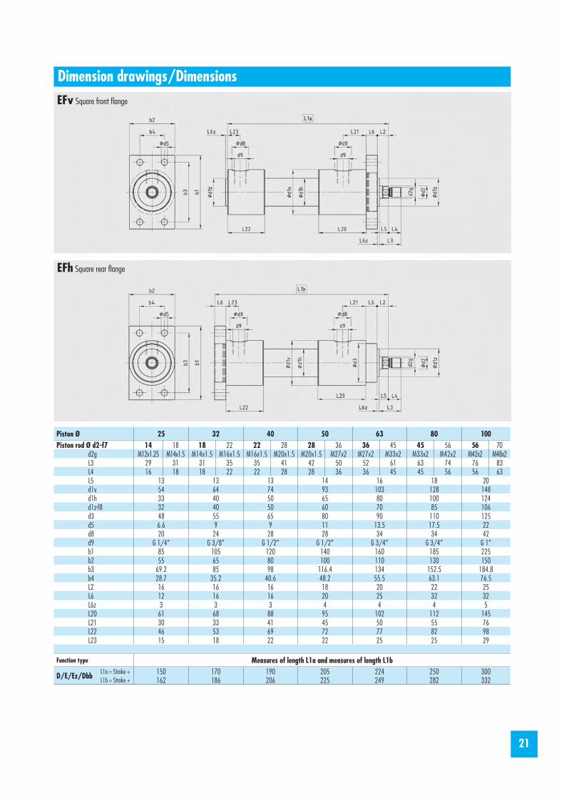
Dimension drawings/Dimensions
Piston Ø 25 32 40 50 63 80 100Piston rod Ø d2-f7 14 18 18 22 22 28 28 36 36 45 45 56 56 70
d2g M12x1.25 M14x1.5 M14x1.5 M16x1.5 M16x1.5 M20x1.5 M20x1.5 M27x2 M27x2 M33x2 M33x2 M42x2 M42x2 M48x2L3 29 31 31 35 35 41 42 50 52 61 63 74 76 83L4 16 18 18 22 22 28 28 36 36 45 45 56 56 63L5 13 13 13 14 16 18 20d1v 54 64 74 93 103 128 148d1h 33 40 50 65 80 100 124d1z-f8 32 40 50 60 70 85 106d3 48 55 65 80 90 110 125d3g M48x1.5 M55x1.5 M65x1.5 M80x1.5 M90x2 M110x2 M125x2d8 20 24 28 28 34 34 42d9 G 1/4” G 3/8” G 1/2” G 1/2” G 3/4” G 3/4” G 1”L2 16 16 16 18 20 22 25L6 12 16 16 20 25 32 32L6z 3 3 3 4 4 4 5L20 61 68 88 95 102 112 145L21 30 33 41 45 50 55 76L22 46 53 69 72 77 82 98L23 15 18 22 22 25 25 29
Function type Measures of length L1aD/E/Ez/Dbb L1a = Stroke + 150 170 190 205 224 250 300
A Basic design
Gv Front thread fastening
21
Dimension drawings/Dimensions
Piston Ø 25 32 40 50 63 80 100Piston rod Ø d2-f7 14 18 18 22 22 28 28 36 36 45 45 56 56 70
d2g M12x1.25 M14x1.5 M14x1.5 M16x1.5 M16x1.5 M20x1.5 M20x1.5 M27x2 M27x2 M33x2 M33x2 M42x2 M42x2 M48x2L3 29 31 31 35 35 41 42 50 52 61 63 74 76 83L4 16 18 18 22 22 28 28 36 36 45 45 56 56 63L5 13 13 13 14 16 18 20d1v 54 64 74 93 103 128 148d1h 33 40 50 65 80 100 124d1z-f8 32 40 50 60 70 85 106d3 48 55 65 80 90 110 125d5 6.6 9 9 11 13.5 17.5 22d8 20 24 28 28 34 34 42d9 G 1/4” G 3/8” G 1/2” G 1/2” G 3/4” G 3/4” G 1”b1 85 105 120 140 160 185 225b2 55 65 80 100 110 130 150b3 69.2 85 98 116.4 134 152.5 184.8b4 28.7 35.2 40.6 48.2 55.5 63.1 76.5L2 16 16 16 18 20 22 25L6 12 16 16 20 25 32 32L6z 3 3 3 4 4 4 5L20 61 68 88 95 102 112 145L21 30 33 41 45 50 55 76L22 46 53 69 72 77 82 98L23 15 18 22 22 25 25 29
Function type Measures of length L1a and measures of length L1b
D/E/Ez/Dbb L1a = Stroke + 150 170 190 205 224 250 300L1b = Stroke + 162 186 206 225 249 282 332
Massbilder/Baumasse
EFv Square front fl ange
EFh Square rear fl ange

22
Dimension drawings/Dimensions
Piston Ø 25 32 40 50 63 80 100Piston rod Ø d2-f7 14 18 18 22 22 28 28 36 36 45 45 56 56 70
d2g M12x1.25 M14x1.5 M14x1.5 M16x1.5 M16x1.5 M20x1.5 M20x1.5 M27x2 M27x2 M33x2 M33x2 M42x2 M42x2 M48x2L3 29 31 31 35 35 41 42 50 52 61 63 74 76 83L4 16 18 18 22 22 28 28 36 36 45 45 56 56 63L5 13 13 13 14 16 18 20d1v 54 64 74 93 103 128 148d1h 33 40 50 65 80 100 124d1z-f8 32 40 50 60 70 85 106d3 48 55 65 80 90 110 125d5 6.6 9 9 11 13.5 17.5 22d8 20 24 28 28 34 34 42d9 G 1/4” G 3/8” G 1/2” G 1/2” G 3/4” G 3/4” G 1”d11 75 92 106 126 145 165 200d12 90 110 130 150 170 200 240L2 16 16 16 18 20 22 25L6 12 16 16 20 25 32 32L6z 3 3 3 4 4 4 5L20 61 68 88 95 102 112 145L21 30 33 41 45 50 55 76L22 46 53 69 72 77 82 98L23 15 18 22 22 25 25 29
Function type Measures of length L1a and measures of length L1b
D/E/Ez/Dbb L1a = Stroke + 150 170 190 205 224 250 300L1b = Stroke + 162 186 206 225 249 282 332
RFv Round front fl ange
RFh Round rear fl ange

23
Dimension drawings/Dimensions
Piston Ø 25 32 40 50 63 80 100Piston rod Ø d2-f7 14 18 18 22 22 28 28 36 36 45 45 56 56 70
d2g M12x1.25 M14x1.5 M14x1.5 M16x1.5 M16x1.5 M20x1.5 M20x1.5 M27x2 M27x2 M33x2 M33x2 M42x2 M42x2 M48x2L3 29 31 31 35 35 41 42 50 52 61 63 74 76 83L4 16 18 18 22 22 28 28 36 36 45 45 56 56 63L5 13 13 13 14 16 18 20d1v 54 64 74 93 103 128 148d1h 33 40 50 65 80 100 124d1z-f8 32 40 50 60 70 85 106d3 48 55 65 80 90 110 125d7-H7 12 16 20 25 32 40 50d8 20 24 28 28 34 34 42d9 G 1/4” G 3/8” G 1/2” G 1/2” G 3/4” G 3/4” G 1”b7 12 16 20 25 32 40 50b8 11 14 18 22 28 32 40L2 16 16 16 18 20 22 25L6 12 16 16 20 25 32 32L6z 3 3 3 4 4 4 5L7 20 25 30 40 50 60 75L8 16 20 25 32 40 50 63L20 61 68 88 95 102 112 145L21 30 33 41 45 50 55 76L24 54 64 80 84 92 104 118L25 23 29 33 34 40 47 49
Function type Measures of length L1cD/E/Ez/Dbb L1c = Stroke + 178 206 231 257 289 332 395
onderausführungen (on request)
Si Swivelling support with gunmetal bush
Sk Hinged support with steel/steel swing support

24
250 bar hydraulic cylinderPiston Ø 20-100 mmLengths of stroke at your option (take account of the bend resistance, see page 35)
Round, compact design;black blued
Piston rod hard chromium plated;with dust seal
Particularly suited for installation into machines and appliances
24
ZU 250 series
Determine your 250 bar hydraulic cylinder:Ordering example: ZU250-G 25/140 Dbb-H03 E11g G1/4“ As4
Cylinder type
å Mounting type
ç Piston Ø
é Length of stroke
è Function type
ê Seal type
ë OptionsEnd of piston rodConnections
í Cover design (for front mounting type)
Special versions on request

25
Piston Ø (mm) 20 25 32 40 50 55 63 70 80 90 100Piston surface pushing (cm²) 3.14 4.90 8.05 12.5 19.6 23.7 31.1 38.5 50.2 63.6 78.5Piston surface pulling (cm²) 2.0 2.9 4.9 7.6 11.6 15.6 18.6 25.9 30.6 44.0 50.2
Lengths of stroke at your option: We manufacture any length of stroke you desire.
ç Piston Ø
é Length of stroke
è Function types
å Mounting types
Double effect Double effetSingle effect Single effect
Single effect
pushing and pulling pulling
pulling with spring return mechanism
pushing with spring return mechanism
pushingwith end position damping on both sides
with end position damping at the back
with end position damping at the frontwith through piston rod
Double effect Double effect Double effect Single effect
Special mounting types: (on request)
Basic design
Front flange Rear flange
Front support bolt
Foot mounting
Centered support bolt Rear support bolt
Fixation filetage
Swivelling support Hinged support
Thread mounting
Special mounting types: (on request)

26
ê Seal types
ë Options
Connections:are manufactured based on the catalog if not otherwise specifi ed by the customer.The position of the connections can be customized.Larger and other (metric) connections are available on request.
As4 Cover with lateral connection (measure of length L1h)As1 Cover with axial connection (measure of length L1v) standard version
Vent screws (ES):are attached to order and in accordance with the position specifi ed by the customer.
í Cover design (for mounting / fastening on the cylinder head)
Standard design
(acc. to your drawing)
Standard version: H00 for hydraulic fl uid (mineral oil). Seal types for other pressure media on request.
Seal types H00 H03 H06 H11Piston seal, grooved ring lPiston seal, PTFE gliding ring l l lRod seal, grooved ring l lRod seal ,PTFE gliding ring l lDust seal l l l lO-rings Nitril l l lO-rings Viton l
Piston speedmax.0.5 m/s l lmax. 10 m/s l l
Temperature range-20/+100 °C l l l-20/+200 °C l
End of piston rod:Standard version: E11 Additional versions as shown in the illustrations are manufactured based on the catalog if not otherwise specifi ed by the customer.Tailor-made versions available on request.
Piston Ø 20 25 32 40 50 55 63 70 80 90 100L22 39 41 44 48 56 57 59 61 64 62 78L23 45 45 53 55 67 67 68 68 72 70 82L24 12 12 15 15 19 19 19 19 20 20 22

27
Dimension drawings/Dimensions
Piston Ø 20 25 32 40 50 55 63 70 80 90 100d1v 35 42 52 65 80 90 100 110 125 135 150d1h 26 33 40 50 65 70 80 90 100 112 124d2-f7 12 16 20 25 32 32 40 40 50 50 60d2g M10 M12 M16 M20 M24 M24 M33 M33 M42 M42 M48d4 9 11 13 16 17 17 22 22 26 26 29d8 16 16 20 20 26 26 26 26 33 33 33d9 G 1/8“ G 1/8“ G 1/4“ G 1/4“ G 3/8“ G 3/8“ G 3/8“ G 3/8“ G 1/2“ G 1/2“ G 1/2“b1 60 70 85 105 130 140 155 170 190 210 230b2 76 90 110 135 162 176 195 210 240 260 280h1±0.1 22 25 32 40 50 56 63 70 80 90 100s1 8.5 10 14 15 17 18 20 22 23 24 26L2 61 61 72 80 95 100 107 115 125 132 145L3 32 40 47 56 63 63 77 77 91 91 100L4 16 22 26 32 35 35 45 45 55 55 60L5 16 18 21 24 28 28 32 32 36 36 40L9 36 33 39 42 50 54 59 63 69 72 80L9b 17 20 20 24 25 28 30 32 34 37 40L10 23 26 30 36 40 42 44 48 51 55 60L11 31 31 39 45 53 58 65 72 79 85 90L12 15 18 20 22 26 28 30 32 34 37 40L13 20 24 27 30 35 38 40 43 45 50 54L22 39 41 44 48 56 57 59 61 64 62 78L23 45 45 53 55 67 67 68 68 72 70 82L24 12 12 15 15 19 19 19 19 20 20 22
Function type Measures of length L1v (with standard cover design As1) and measures of length L1h (with cover design As4)
D/E/Ez L1v = Stroke + 91 96 112 124 141 150 161 174 185 197 209L1h = Stroke + 97 100 121 131 152 160 170 181 193 205 213
Dbb L1v = Stroke + 103 110 128 142 161 170 183 196 209 221 237L1h = Stroke + 109 114 137 149 172 180 192 203 217 229 241
Minimum measures of length L1v und L1h L1v = 101 103 117 129 152 158 167 177 190 195 224L1h = 107 107 126 136 163 168 176 184 198 203 228
A Basic design
H/H2 H: Front foot/H2: two feet

28
Dimension drawings/Dimensions
Piston Ø 20 25 32 40 50 55 63 70 80 90 100d1v 35 42 52 65 80 90 100 110 125 135 150d1h 26 33 40 50 65 70 80 90 100 112 124
d2-f7 12 16 20 25 32 32 40 40 50 50 60d2g M10 M12 M16 M20 M24 M24 M33 M33 M42 M42 M48d3 G ¾“ G 1“ G 1 ¼“ G 1 ½“ G 2“ G 2“ G 2 ½“ G 2 ½“ G 3“ G 3“ G 4“
d3z-h7 28 38 46 56 70 75 90 90 110 110 125d8 16 16 20 20 26 26 26 26 33 33 33d9 G 1/8“ G 1/8“ G 1/4“ G 1/4“ G 3/8“ G 3/8“ G 3/8“ G 3/8“ G 1/2“ G 1/2“ G 1/2“L2 61 61 72 80 95 100 107 115 125 132 145L3 32 40 47 56 63 63 77 77 91 91 100L4 16 22 26 32 35 35 45 45 55 55 60L5 16 18 21 24 28 28 32 32 36 36 40L6 9 11 14 16 20 20 25 25 35 35 40L6z 13.5 16 21 23 30 30 35 35 49 49 54L11 31 31 39 45 53 58 65 72 79 85 90L22 39 41 44 48 56 57 59 61 64 62 78L23 45 45 53 55 67 67 68 68 72 70 82L24 12 12 15 15 19 19 19 19 20 20 22
Function type Measures of length L1v (with standard cover design As1) and measures of length L1h (with cover design As4)
D/E/EzL1v = Stroke + 91 96 112 124 141 150 161 174 185 197 209L1h = Stroke + 97 100 121 131 152 160 170 181 193 205 213
Dbb L1v = Stroke + 103 110 128 142 161 170 183 196 209 221 237L1h = Stroke + 109 114 137 149 172 180 192 203 217 229 241
Minimum measures of length L1v und L1hL1v = 101 103 117 129 152 158 167 177 190 195 224L1h = 107 107 126 136 163 168 176 184 198 203 228
G Thread fastening
Gz Thread fastening with centering

29
Dimension drawings/Dimensions
Piston Ø 20 25 32 40 50 55 63 70 80 90 100d1v 35 42 52 65 80 90 100 110 125 135 150d1h 26 33 40 50 65 70 80 90 100 112 124d2-f7 12 16 20 25 32 32 40 40 50 50 60d2g M10 M12 M16 M20 M24 M24 M33 M33 M42 M42 M48d5 7 9 11 13.5 13.5 13.5 17.5 17.5 17.5 17.5 20d8 16 16 20 20 26 26 26 26 33 33 33d9 G 1/8“ G 1/8“ G 1/4“ G 1/4“ G 3/8“ G 3/8“ G 3/8“ G 3/8“ G 1/2“ G 1/2“ G 1/2“b3 40 48 62 75 85 95 105 110 125 130 150b4 55 70 85 100 115 125 140 145 160 165 190s2 9 11 14 16 20 20 25 25 35 35 40s3 20 20 25 25 30 30 30 30 30 30 30L2 61 61 72 80 95 100 107 115 125 132 145L3 32 40 47 56 63 63 77 77 91 91 100L4 16 22 26 32 35 35 45 45 55 55 60L5 16 18 21 24 28 28 32 32 36 36 40L11 31 31 39 45 53 58 65 72 79 85 90L22 39 41 44 48 56 57 59 61 64 62 78L23 45 45 53 55 67 67 68 68 72 70 82L24 12 12 15 15 19 19 19 19 20 20 22
Function type Measures of length L1v and measures of length L1h (with cover design As4)
D/E/EzL1v = Stroke + 91 96 112 124 141 150 161 174 185 197 209L1h = Stroke + 97 100 121 131 152 160 170 181 193 205 213
Dbb L1v = Stroke + 103 110 128 142 161 170 183 196 209 221 237L1h = Stroke + 109 114 137 149 172 180 192 203 217 229 241
Minimum measures of length L1v und L1hL1v = 101 103 117 129 152 158 167 177 190 195 224L1h = 107 107 126 136 163 168 176 184 198 203 228
Fv Front fl ange
Fh Rear fl ange

30
Dimension drawings/Dimensions
Piston Ø 20 25 32 40 50 55 63 70 80 90 100d1v 35 42 52 65 80 90 100 110 125 135 150d1h 26 33 40 50 65 70 80 90 100 112 124d2-f7 12 16 20 25 32 32 40 40 50 50 60d2g M10 M12 M16 M20 M24 M24 M33 M33 M42 M42 M48d7-H7 12 16 20 25 32 32 40 40 50 50 60d8 16 16 20 20 26 26 26 26 33 33 33d9 G 1/8“ G 1/8“ G 1/4“ G 1/4“ G 3/8“ G 3/8“ G 3/8“ G 3/8“ G 1/2“ G 1/2“ G 1/2“d17-H7 12 15 20 25 30 30 40 40 50 50 60b7 12 16 20 25 32 32 40 40 50 50 60b16 10 12 16 20 22 22 28 28 35 35 44b17 13 15 21 27 29 29 34 34 41 41 52L2 61 61 72 80 95 100 107 115 125 132 145L3 32 40 47 56 63 63 77 77 91 91 100L4 16 22 26 32 35 35 45 45 55 55 60L5 16 18 21 24 28 28 32 32 36 36 40L7 12 16 20 25 32 32 40 40 50 50 60L7a 20 25 28 35 42 42 52 52 65 65 78L8 11.5 15 19 24 31 31 38 38 48 48 58L8a 17.5 21 26 32.5 40 40 50 50 62.5 62.5 75L11 31 31 39 45 53 58 65 72 79 85 90L23 45 45 53 55 67 67 68 68 72 70 82L24 12 12 15 15 19 19 19 19 20 20 22
Function type Measures of length L1h D/E/Ez L1h = Stroke + 97 100 121 131 152 160 170 181 193 205 213Dbb L1h = Stroke + 109 114 137 149 172 180 192 203 217 229 241
Minimum measures of length L1hL1h = 107 107 126 136 163 168 176 184 198 203 228
Si Swivelling support with gunmetal bush
Sk Hinged support with steel/steel swing support

31
Hydraulic cylinders with pressure-resistant inductive proximity switches for end position sensing.
Design: PNP/normally open contact (short circuit-resistant). Dimensions: on requestThe proximity switches are attached 180° (opposite) to the connections if not otherwise specifi ed by the customer.
Available versions:Piston Ø: minimum piston Ø 10 mmLengths of stroke at your option: We manufacture any length of stroke you desireFunction types: D, DbbSeal version: Standard version: H03
Dimensions: on requestwith connecting plate for directional control valve on request (NG6/NG10)
Available versions:Piston Ø: minimum piston Ø 20 mmLengths of stroke at your option: We manufacture any length of stroke you desireFunction types: D, Dbbseal versions: Standard version: H40 Piston with sliding ring PTFE and driving band Piston rod with tandem sealing (sliding-ring seal/grooved ring and dust seal)
For high-precision positioning, adjusting and controlling movements, our hydraulic cylinders can be equipped with contactlessly operating path measurement systems.
Dimensions: on request
Available versions:Piston Ø: minimum piston Ø 40 mmLengths of stroke at your option: We manufacture any length of stroke you desireFunction type: D
Path sensors for: (dimensions on request) analog interface digital pulse interface SSD interface CANopen interface
Hydraulic cylinders with end position sensing
Hydraulic cylinders in servo quality
Hydraulic cylinders with path-measuring system
ZH100 = hydraulic cylinder for operational pressures up to 100 barZH250 = hydraulic cylinder for operational pressures up to 250 bar
Dimensions: on request
Available versions:Piston Ø: 100–250 mmLengths of stroke at your option: We manufacture any length of stroke you desireFunction types: D, DbbSeal version: standard version: H00
Hydraulic cylinders with piston Ø100-250 mm
Special versions (on request)

3232
ZHSS Series
400 bar clamping cylinderPiston Ø 16-50 mmStandard lengths of stroke
Single-effect pushing operation; with or without spring return mechanism
Round, compact design;black blued
piston rod hardened;with dust seal

33
General information
Mounting types
General dimensions
Piston Ø (mm) 16 20 25 32 40 50Piston surface pushing (cm²) 2.01 3.14 4.91 8.04 12.56 19.63Piston force (daN) pushing at 100 bar 201 314 491 804 1256 1963
160 bar 321 502 785 1286 2010 3140250 bar 502 785 1227 2010 3140 4907400 bar 804 1256 1964 2316 5024 7852
Spring force (daN) stressed 12 14 24 30 50 72pre-stressed 6 7 12 15 25 36
Function type Type Stroke L1 L3 Le L5 L6/L7 d1v d1h-h8 d1g d2-h7 d2g d3ZHSS 16-1 4 45 13.5 10 2.5
Leng
ths L6
and L
7 ca
n be c
hose
n
30 25 M25x1.5 10 M5 G 1/8“ZHSS 16-2 8 58ZHSS 20-1 5 50 15 10 3 36 30 M30x1.5 12 M5 G 1/8“ZHSS 20-2 10 68ZHSS 25-1 6 55 18 12 3 45 36 M35x1.5 15 M6 G 1/4“ZHSS 25-2 12 76ZHSS 32-1 8 63 20 16 4 55 45 M45x1.5 20 M8 G 1/4“ZHSS 32-2 16 91ZHSS 40-1 10 70 21 20 6 65 55 M55x1.5 25 M10 G 1/4“ZHSS 40-2 20 105ZHSS 50-1 12 78 24 24 6 82 70 M70x2 32 M12 G 1/4“ZHSS 50-2 24 120ZHSS 16-3 18 45 13.5 10 2.5 30 25 M25x1.5 10 M5 G 1/8“ZHSS 16-4 31 58ZHSS 20-3 20 50 15 10 3 36 30 M30x1.5 12 M5 G 1/8“ZHSS 20-4 38 68ZHSS 25-3 27 55 18 12 3 45 36 M35x1.5 15 M6 G 1/4“ZHSS 25-4 48 76ZHSS 32-3 28 63 20 16 4 55 45 M45x1.5 20 M8 G 1/4“ZHSS 32-4 56 91ZHSS 40-3 38 70 21 20 6 65 55 M55x1.5 25 M10 G 1/4“ZHSS 40-4 73 105ZHSS 50-3 40 78 24 24 6 82 70 M70x2 32 M12 G 1/4“ZHSS 50-4 82 120
Basic design With retaining ring (DIN 471) With thread and slotted nut
Ordering example: ZHSS 25-3 ZHSS 25-3 L7 = 10 mm ZHSS 25-3 d1g = M35x1.5 L6 = 30 mm

34
Swivel head GE with gunmetal bush
Fork joint GG (acc. to ISO 8140, with stainless steel bolt)
Larger threads for the swivel head GE available on request.
Typ a Ø h-h8 i n o p
Typ d2g Ø d1-H7 Ø d2 b1 b2 h L1 R
Joint head GS (DIN 24338, ISO 6982, sliding contact surface combin.: steel/steel) Typ Ø d-H7 A B C-h12 G G1 H H1 H2 N N1 N2
GG - M 4GG - M 6GG - M 8GG - M 10 x 1.25GG - M 12 x 1.25GG - M 16 x 1.5GG - M 20 x 1.5GG - M 27 x 2GG - M 36 x 2
M 4 M 6 M 8
M 10 x 1.25M 12 x 1.25M 16 x 1.5M 20 x 1.5M 27 x 2M 36 x 2
468
101216203035
81216202432405570
16243240486480
110144
213142526283
105148188
468
101216203035
GS 12GS 16GS 20GS 25GS 32GS 40GS 50GS 63
1216202532405063
324047587089
108132
1216202532405063
10.513172127324052
M 12 x 1.25M 14 x 1.5M 16 x 1.5M 20 x 1.5M 27 x 2M 33 x 2M 42 x 2M 48 x 2
1719232937465764
384452658097
120140
1418222732415062
54647796
118145.5179211
32404754668096
114
1621253038475870
1211.5141722263238
Accessories – Piston rod knuckles
GE 5GE 6GE 8
GE 10GE 12GE 14GE 16GE 20GE 24GE 27GE 33GE 42GE 48GE 52
M 5M 6M 8
M 10M 12M 14M 16M 20M 24M 27M 33M 42M 48M 52
68
101214162025253240506080
68
101214162025323240506080
101215202025304040506080
100100
1820252530304050506080
100120120
1820242832364250607080
100125125
1314171922252934445055707676
910
12.512.51515202525304050––

35
Ømm 01 Ømm 21 Ømm 61 Ømm 02 Ømm 52 Ø
mm 23 Ø
mm 04 Ø
mm 05 Ø
mm 36 Ø
mm 08 Ø
mm 001 Ø
mm 521 Ø
mm 061 Ø
mm 002 250
200
160
140
120
100
80
60
40
20
5
10,0 1,
0 1 5 6 7 8 9 01 02 03 05 06 07 08 09 001
002
003
008
009
005
0 06
007
000 1
0,01
0,02
0,03
0,04
0,05
0,06
0,070,080,090,1
0,2
0,3
0,4
0,5
0,6
0,70,80,91 2 3 4 5 6 7 8 9 10 20 30 200
300
40 50 60 70 80 90 100
4 000
3 000
2 000
1 000900800700600
500
400
300
200
100
Ø 8 mm
Ø 6 mm
Ø 4 mm
Ø 10 mmØ 12 mm
Ø 14 mmØ 16 mm
Ø 18 mmØ 20 mm
Ø 22 mmØ 25 mm
Ø 28 mmØ 32 mm
Ø 36 mmØ 40 mm
Ø 45 mmØ 50 mm
Ø 56 mmØ 60 mm
Piston rods with adequate diameters should be provided for if cylinders with a long stroke are used. The length of stroke is limited depending on pressure, type of fastening, type of connection of the rod end and guide quality of the moved mass.The above diagram applies only for rigidly guided mass and front or back flange fastening.
Attention: The max. permitted bending length must be calculated in case of a deviating type of fastening. We calculate for you the piston rod diameter required based on your description of the planned use. The diagram ”Determination of the piston rod diameter required“ applies only to the mounting described.
Opera
ting p
ressu
re in
bar
Piston force (KN), theoretical force, without considering the coeffi cient of effi ciency
Bend
ing le
ngth
(mm)
Load on the piston rod (KN)
Piston force and bending length
Determination of the cylinder diameter required
Determination of the piston rod diameter required