Embed Size (px)
Citation preview

Flow Measurement and Control

Orifice Meter
The orifice meter consists of an accurately machined and drilled plate concentrically mounted between two flanges. The position of the pressure taps is somewhat arbitrary.

Orifice Meter
The orifice meter has several practical advantages when compared to venturi meters.
• Lower cost• Smaller physical size• Flexibility to change throat to pipe diameter
ratio to measure a larger range of flow rates
Disadvantage:• Large power consumption in the form of
irrecoverable pressure loss
Orifice MeterThe development of the orifice meter equation is similar to that of the venturi meter and gives:
0
4
0 2
1
SVq
ppCV ba
where: = ratio of orifice diameter to pipe diameter ≈ 0.5 usuallyS0 = cross sectional area of orificeV = bulk velocity through the orificeC0 = orifice coefficient ≈ 0.61 for Re > 30,000
–

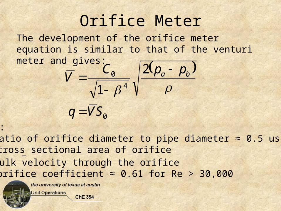
There is a large pressure drop much of which is not recoverable. This can be a severe limitation when considering use of an orifice meter.
Pressure Loss inOrifice Meters

ASME Design Standards
Fluid Meters: Their Theory and Applications, 6th ed., American Society of Mechanical Engineers, New York, 1971 pp. 58-65.

RotametersRotameters fall into the category of flow measurement devices called variable area meters. These devices have nearly constant pressure and depend on changing cross sectional area to indicate flow rate. Rotameters are extremely simple, robust devices that can measure flow rates of both liquids and gasses.
Fluid flows up through the tapered tube and suspends a ‘float’ in the column of fluid. The position of the float indicates the flow rate on a marked scale.

Rotameters
Three types of forces must be accounted for when analyzing rotameter performance:
• Flow• Gravity• Buoyancy
Flow
Buoyancy
Gravity
For our analysis neglect drag effect

RotameterMass Balance
Assume Gradual Taper
S
QVV
SVSV
21
21
Flow Between Float and Tube
313 S
SV
SS
QV
f
S3 is annular flow area at plane 3

Rotameter
Momentum BalanceNote:• p3 = p2
• Must account for force due to float
fff gVVzSgSppVVQ 2113
bf
S
gV
S
S
S
Qzg
p
3
2
1

Rotameter
Mechanical Energy Balance
fhp
zgVVW
21
232
1ˆ
0
2
23VKh Rf Assume: (Base velocity head on
smallest flow area)
2
3
21
2
3
21
212
1
S
SVK
S
SVVzg
pR
Rotameter
2
3
2
3
2
112
11
S
SK
S
Q
S
gV
S
S
S
QR
bf
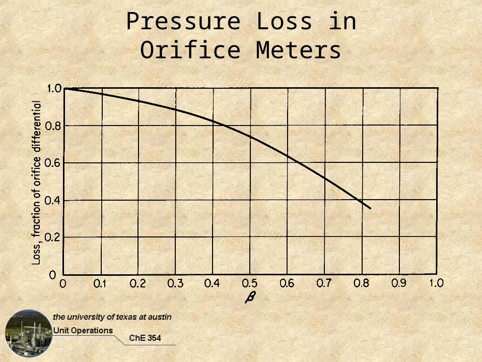
Combining Momentum and Mechanical Energy Balance
After Some Manipulation
f
f
f
fR
f
S
gV
SSK
SSSQ
2
1 23

Rotameter
Assuming Sf ≈ S a discharge coefficient can be defined 211 RR KC
CR must be determined experimentally. As Q increases the float rides higher, the assumption that Sf = S is poorer, and the previous expression is more nearly correct.
f
f
fR S
gVCSQ
23

Other Flow Meters

Turbine Meter
Measure by determining RPM of turbine (3) via sensor (6). Turbine meters are accurate but fragile.

Coriolis Meters
When fluid is passed through a U-bend, it imposes a force on the tube wall perpendicular to the flow direction (Coriolis force). The deformation of the U-tube is proportional to the flow rate. Coriolis meters are expensive but highly accurate.

Pneumatic Control Valves

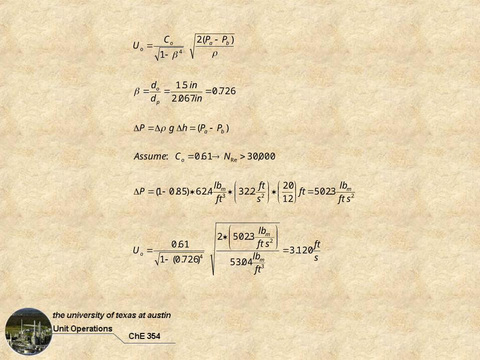
Orifice Meter Example
A 2 in. Schedule 40 pipe carries 35º API distillate at 50° F (SG=0.85). The flow rate is measured by an orifice meter which has a diameter of 1.5 in. The pressure drop across the orifice plate is measured by a water manometer connected to the flange taps. If the manometer reading is 20 in. of H2O, what is the flow rate of the oil in GPM ?
s
ft
ftlbsftlb
U
sft
lbft
s
ft
ft
lbP
NCAssume
PPhgP
in
in
d
d
PPCU
m
m
o
mm
o
ba
p
o
baoo
120.304.53
3.5022
)726.0(1
61.0
3.50212
202.324.62)85.01(
000,3061.0:
)(
726.0067.2
5.1
)(2
1
3
2
4
223
Re
4

000,306840107197.6
5.4
3
04.53120.312
5.1
2.17min
6048.7120.3
412
5.1
4
4
3
.2
.2
cPsft
lb
cP
ft
lb
sft
ftUd
N
GPMs
ft
gal
s
ftft
Ud
Q
m
m
ooRE
oo
Now what ???