Embed Size (px)
Citation preview
Flow Equations for Sizing Control Valves
Approved 3 July 2002
ANSI/ISA–75.01.01–2002 (IEC 60534-2-1 Mod)
A M E R I C A N N A T I O N A L S T A N D A R D
ISA The Instrumentation,Systems, and
Automation Society
–TM
NOTICE OF COPYRIGHTThis is a copyrighted document and may not be copied or distributed in anyform or manner without the permission of ISA. This copy of the document wasmade for the sole use of the person to whom ISA provided it and is subject tothe restrictions stated in ISA’s license to that person. It may not be provided toany other person in print, electronic, or any other form. Violations of ISA’scopyright will be prosecuted to the fullest extent of the law and may result insubstantial civil and criminal penalties.
Copia
para
perfe
ccion
amien
to
Copia
para
perfe
ccion
amien
to

ANSI/ISA-75.01.01-2002 (60534-2-1 Mod)Flow Equations for Sizing Control Valves
ISBN: 1-55617-780-1
Copyright 2002 by ISA–The Instrumentation, Systems, and Automation Society. All rights reserved.Not for resale. Printed in the United States of America. No part of this publication may be reproduced,stored in a retrieval system, or transmitted, in any form or by any means (electronic, mechanical,photocopying, recording, or otherwise), without the prior written permission of the Publisher.
ISA67 Alexander DriveP. O. Box 12277Research Triangle Park, North Carolina 27709USA
Copia
para
perfe
ccion
amien
to
Copia
para
perfe
ccion
amien
to
- 3 - ANSI/ISA-75.01.01-2002 (IEC 60534-2-1 Mod)
Preface
This preface, as well as all footnotes and annexes, is included for information purposes and is not part ofANSI/ISA-75.01.01-2002 (IEC 60534-2-1 Mod).
The standards referenced within this document may contain provisions which, through reference in thistext, constitute requirements of this document. At the time of publication, the editions indicated were valid.All standards are subject to revision, and parties to agreements based on this document are encouragedto investigate the possibility of applying the most recent editions of the standards indicated within thisdocument. Members of IEC and ISO maintain registers of currently valid International Standards. ANSImaintains registers of currently valid U.S. National Standards.
This document has been prepared as part of the service of ISA—The Instrumentation, Systems, andAutomation Society, toward a goal of uniformity in the field of instrumentation. To be of real value, thisdocument should not be static but should be subject to periodic review. Toward this end, the Societywelcomes all comments and criticisms and asks that they be addressed to the Secretary, Standards andPractices Board; ISA; 67 Alexander Drive; P. O. Box 12277; Research Triangle Park, NC 27709;Telephone (919) 549-8411; Fax (919) 549-8288; E-mail: [email protected].
The ISA Standards and Practices Department is aware of the growing need for attention to the metricsystem of units in general, and the International System of Units (SI) in particular, in the preparation ofinstrumentation standards. The Department is further aware of the benefits to USA users of ISA standardsof incorporating suitable references to the SI (and the metric system) in their business and professionaldealings with other countries. Toward this end, this Department will endeavor to introduce SI-acceptablemetric units in all new and revised standards, recommended practices, and technical reports to thegreatest extent possible. Standard for Use of the International System of Units (SI): The Modern MetricSystem, published by the American Society for Testing & Materials as IEEE/ASTM SI 10-97, and futurerevisions, will be the reference guide for definitions, symbols, abbreviations, and conversion factors.
It is the policy of ISA to encourage and welcome the participation of all concerned individuals and interestsin the development of ISA standards, recommended practices, and technical reports. Participation in theISA standards-making process by an individual in no way constitutes endorsement by the employer of thatindividual, of ISA, or of any of the standards, recommended practices, and technical reports that ISAdevelops.
CAUTION — ISA ADHERES TO THE POLICY OF THE AMERICAN NATIONAL STANDARDSINSTITUTE WITH REGARD TO PATENTS. IF ISA IS INFORMED OF AN EXISTING PATENT THAT ISREQUIRED FOR USE OF THE STANDARD, IT WILL REQUIRE THE OWNER OF THE PATENT TOEITHER GRANT A ROYALTY-FREE LICENSE FOR USE OF THE PATENT BY USERS COMPLYINGWITH THE STANDARD OR A LICENSE ON REASONABLE TERMS AND CONDITIONS THAT AREFREE FROM UNFAIR DISCRIMINATION.
EVEN IF ISA IS UNAWARE OF ANY PATENT COVERING THIS STANDARD, THE USER ISCAUTIONED THAT IMPLEMENTATION OF THE STANDARD MAY REQUIRE USE OF TECHNIQUES,PROCESSES, OR MATERIALS COVERED BY PATENT RIGHTS. ISA TAKES NO POSITION ON THEEXISTENCE OR VALIDITY OF ANY PATENT RIGHTS THAT MAY BE INVOLVED IN IMPLEMENTINGTHE STANDARD. ISA IS NOT RESPONSIBLE FOR IDENTIFYING ALL PATENTS THAT MAYREQUIRE A LICENSE BEFORE IMPLEMENTATION OF THE STANDARD OR FOR INVESTIGATINGTHE VALIDITY OR SCOPE OF ANY PATENTS BROUGHT TO ITS ATTENTION. THE USER SHOULDCAREFULLY INVESTIGATE RELEVANT PATENTS BEFORE USING THE STANDARD FOR THEUSER’S INTENDED APPLICATION.
Copia
para
perfe
ccion
amien
to
Copia
para
perfe
ccion
amien
to

ANSI/ISA–75.01.01–2002 (IEC 60534-2-1 Mod) – 4 –
HOWEVER, ISA ASKS THAT ANYONE REVIEWING THIS STANDARD WHO IS AWARE OF ANYPATENTS THAT MAY IMPACT IMPLEMENTATION OF THE STANDARD NOTIFY THE ISASTANDARDS AND PRACTICES DEPARTMENT OF THE PATENT AND ITS OWNER.
ADDITIONALLY, THE USE OF THIS STANDARD MAY INVOLVE HAZARDOUS MATERIALS,OPERATIONS OR EQUIPMENT. THE STANDARD CANNOT ANTICIPATE ALL POSSIBLEAPPLICATIONS OR ADDRESS ALL POSSIBLE SAFETY ISSUES ASSOCIATED WITH USE INHAZARDOUS CONDITIONS. THE USER OF THIS STANDARD MUST EXERCISE SOUNDPROFESSIONAL JUDGMENT CONCERNING ITS USE AND APPLICABILITY UNDER THE USER’SPARTICULAR CIRCUMSTANCES. THE USER MUST ALSO CONSIDER THE APPLICABILITY OFANY GOVERNMENTAL REGULATORY LIMITATIONS AND ESTABLISHED SAFETY AND HEALTHPRACTICES BEFORE IMPLEMENTING THIS STANDARD.
The following people served as members of ISA Subcommittee SP75.01:
NAME COMPANY
W. Weidman, Managing Director Parsons Energy & Chemicals GroupJ. George, Chair Richards IndustriesH. Baumann H. B. Services Partners LLCH. Boger* Masoneilan DresserG. Borden ConsultantS. Boyle Metso Automation USA Inc.C. Crawford ConsultantA. Glenn Flowserve CorporationM. Hanusa* Fisher Controls International Inc.H. Hoffmann Samson AGJ. McCaskill Power ChokesA. McCauley Chagrin Valley Controls Inc.J. Ozol Northern States PowerW. Rahmeyer Utah State UniversityJ. Reed NorrisealJ. Reid Cashco Inc.M. Riveland* Fisher Controls International Inc.K. Roth Arthur D. LittleK. Schoonover Con-Tek Valves Inc.E. Skovgaard Leslie Controls Inc.D. Van Staveren Bechtel CorporationF. Volpe* Masoneilan Dresser______ * One vote per company.
Copia
para
perfe
ccion
amien
to
Copia
para
perfe
ccion
amien
to

- 5 - ANSI/ISA-75.01.01-2002 (IEC 60534-2-1 Mod)
The following people served as members of ISA Committee SP75:
NAME COMPANY
W. Weidman, Managing Director Parsons Energy & Chemicals GroupD. Buchanan, Chair ConsultantA. Abromaitis Red Valve Company, Inc.H. Backinger ConsultantG. Barb ConsultantH. Baumann H. B. Services Partners LLCJ. Beall* Emerson Process ManagementK. Black Curtiss-Wright Flow Control CorporationW. Blackwell Industrial ValveH. Boger* Masoneilan DresserG. Borden ConsultantS. Boyle Metso Automation USA Inc.R. Brodin Fisher Controls International, Inc.F. Cain Flowserve CorporationA. Engels Praxair, Inc.H. Fuller Valvcon CorporationJ. George Richards IndustriesJ. Jamison Bantrel, Inc.R. Jeanes TXU ElectricJ. Kersh M. W. Kellogg CompanyC. Langford Cullen G. Langford, Inc.W. Lestan* Dresser Valve DivisionA. Libke SPX Valves & Controls DeZurik ProductsR. Louviere Services UnlimitedJ. McCaskill Power ChokesA. McCauley Chagrin Valley Controls, Inc.R. McEver* Emerson Valve AutomationH. Miller Control Components, Inc.T. Molloy CMES Inc.L. Ormanoski Frick CompanyJ. Ozol Northern States PowerW. Rahmeyer Utah State UniversityJ. Reed NorrisealK. Schoonover Con-Tek Valves, Inc.A. Shea* SPX Valves & ControlsE. Skovgaard Leslie Controls, Inc.H. Sonderegger Anvil International Inc.
______ * One vote per company.
Copia
para
perfe
ccion
amien
to
Copia
para
perfe
ccion
amien
to

ANSI/ISA–75.01.01–2002 (IEC 60534-2-1 Mod) – 6 –
This standard was approved for publication by the ISA Standards and Practices Board on 8 April 2002.
NAME COMPANY
M. Zielinski Emerson Process ManagementD. Bishop David N Bishop, ConsultantD. Bouchard PapricanM. Cohen ConsultantM. Coppler Ametek, Inc.B. Dumortier Schneider ElectricW. Holland Southern CompanyE. Icayan ACES IncA. Iverson Ivy OptiksR. Jones Dow Chemical CompanyV. Maggioli Feltronics CorporationT. McAvinew ForeRunner CorporationA. McCauley, Jr. Chagrin Valley Controls, Inc.G. McFarland Westinghouse Process Control Inc.R. Reimer Rockwell AutomationJ. Rennie Factory Mutual Research CorporationH. Sasajima Yamatake CorporationI. Verhappen Syncrude Canada Ltd.R. Webb POWER EngineersW. Weidman Parsons Energy & Chemicals GroupJ. Weiss KEMA ConsultingM. Widmeyer ConsultantC. Williams Eastman Kodak CompanyG. Wood Graeme Wood Consulting
Copia
para
perfe
ccion
amien
to
Copia
para
perfe
ccion
amien
to
- 7 - ANSI/ISA-75.01.01-2002 (IEC 60534-2-1 Mod)
Contents
1 Scope................................................................................................................................................... 11
2 Normative references........................................................................................................................... 11
3 Definitions ............................................................................................................................................ 11
4 Installation............................................................................................................................................ 12
5 Symbols ............................................................................................................................................... 13
6 Sizing equations for incompressible fluids ........................................................................................... 14
6.1 Turbulent flow ............................................................................................................................... 14
6.2 Non-turbulent (laminar and transitional) flow................................................................................ 15
7 Sizing equations for compressible fluids .............................................................................................. 16
7.1 Turbulent flow ............................................................................................................................... 16
7.2 Non-turbulent (laminar and transitional) flow................................................................................ 18
8 Determination of correction factors ...................................................................................................... 19
8.1 Piping geometry factor FP ............................................................................................................. 19
8.2 Reynolds number factor FR ........................................................................................................... 20
8.3 Liquid pressure recovery factors FL or FLP..................................................................................... 21
8.4 Liquid critical pressure ratio factor FF............................................................................................ 21
8.5 Expansion factor Y........................................................................................................................ 22
8.6 Pressure differential ratio factor xT or xTP....................................................................................... 22
8.7 Specific heat ratio factor Fγ........................................................................................................... 23
8.8 Compressibility factor Z ................................................................................................................ 23
Annex A (informative) — Derivation of valve style modifier Fd .................................................................... 35
Annex B (informative) — Control valve sizing flow charts........................................................................... 41
Annex C (informative) — Physical constants 1)............................................................................................ 45
Annex D (informative) — Alternate non-turbulent flow calculation method................................................. 47
Annex E (informative) — Units conversions................................................................................................ 51
Copia
para
perfe
ccion
amien
to
Copia
para
perfe
ccion
amien
to

ANSI/ISA–75.01.01–2002 (IEC 60534-2-1 Mod) – 8 –
Annex F (informative) — Examples of sizing calculations........................................................................... 55
Annex G (informative) — Equations for Reynolds number factor, FR.......................................................... 71
Annex H (informative) — Bibliography ........................................................................................................ 73
Copia
para
perfe
ccion
amien
to
Copia
para
perfe
ccion
amien
to

- 9 - ANSI/ISA-75.01.01-2002 (IEC 60534-2-1 Mod)
FOREWORD
NOTE This foreword is included for information purposes only and is identical to the foreword found in IEC 60534-2-1.
1) The IEC (International Electrotechnical Commission) is a worldwide organization for standardizationcomprising all national electrotechnical committees (IEC National Committees). The object of the IEC is topromote international co-operation on all questions concerning standardization in the electrical andelectronic fields. To this end and in addition to other activities, the IEC publishes International Standards.Their preparation is entrusted to technical committees; any IEC National Committee interested in thesubject dealt with may participate in this preparatory work. International, governmental and non-governmental organizations liaising with the IEC also participate in this preparation. The IEC collaboratesclosely with the International Organization for Standardization (ISO) in accordance with conditionsdetermined by agreement between the two organizations.
2) The formal decisions or agreements of the IEC on technical matters express, as nearly as possible, aninternational consensus of opinion on the relevant subjects since each technical committee hasrepresentation from all interested National Committees.
3) The documents produced have the form of recommendations for international use and are publishedin the form of standards, technical reports or guides and they are accepted by the National Committees inthat sense.
4) In order to promote international unification, IEC National Committees undertake to apply IECInternational Standards transparently to the maximum extent possible in their national and regionalstandards. Any divergence between the IEC Standard and the corresponding national or regional standardshall be clearly indicated in the latter.
5) The IEC provides no marking procedure to indicate its approval and cannot be rendered responsiblefor any equipment declared to be in conformity with one of its standards.
6) Attention is drawn to the possibility that some of the elements of this International Standard may bethe subject of patent rights. The IEC shall not be held responsible for identifying any or all such patentrights.
International Standard IEC 60534-2-1 has been prepared by subcommittee 65B: Devices, of IEC technicalcommittee 65: Industrial-process measurement and control.
The text of this standard is based on the following documents:
FDIS Report on voting
65B/347/FDIS 65B/357/RVD
Full information on the voting for the approval of this standard can be found in the report on votingindicated in the above table.
The current edition of IEC 60534-2-1 cancels and replaces the first edition of both IEC 60534-2 publishedin 1978, and IEC 60534-2-2 published in 1980, which cover incompressible and compressible fluid flow,respectively.
IEC 60534-2-1 covers sizing equations for both incompressible and compressible fluid flow.
Copia
para
perfe
ccion
amien
to
Copia
para
perfe
ccion
amien
to

ANSI/ISA–75.01.01–2002 (IEC 60534-2-1 Mod) – 10 –
Annexes A, B, C, D F, G, and H are for information only.
A bilingual version of this standard may be issued at a later date.
Copia
para
perfe
ccion
amien
to
Copia
para
perfe
ccion
amien
to
- 11 - ANSI/ISA-75.01.01-2002 (IEC 60534-2-1 Mod)
1 Scope
ANSI/ISA-75.01.01-2002 includes equations for predicting the flow coefficient of compressible andincompressible fluids through control valves.
The equations for incompressible flow are based on standard hydrodynamic equations for Newtonianincompressible fluids. They are not intended for use when non-Newtonian fluids, fluid mixtures, slurries, orliquid-solid conveyance systems are encountered.
At very low ratios of pressure differential to absolute inlet pressure (∆P/P1), compressible fluids behavesimilarly to incompressible fluids. Under such conditions, the sizing equations for compressible flow can betraced to the standard hydrodynamic equations for Newtonian incompressible fluids. However, increasingvalues of ∆P/P1 result in compressibility effects that require that the basic equations be modified byappropriate correction factors. The equations for compressible fluids are for use with gas or vapor and arenot intended for use with multiphase streams such as gas-liquid, vapor-liquid or gas-solid mixtures.
For compressible fluid applications, this part of ANSI/ISA-75.01.01-2002 is valid for all valves. However,manufacturers of some valves with xT ≥ 0.84 have reported minor inaccuracies (see Annex H). Cautionmust also be exercised when applying the equations for compressible fluids to gaseous mixtures ofcompounds, particularly near phase boundaries.
The accuracy of results computed with the equations in this standard will be governed by the accuracy ofthe constituent coefficients and the process data supplied. Methods of evaluating the coefficients used inthe equations presented herein are given in ANSI/ISA-75.02-1996. The stated accuracy associated withthe coefficients in that document is ±5% when Cv /d 2 < 0.047 N18. Reasonable accuracy can only bemaintained for control valves if Cv /d 2 < 0.047 N18.
2 Normative references
The following normative documents contain provisions which, through reference in this text, constituteprovisions of this part of ANSI/ISA-75.01.01-2002. At the time of publication, the editions indicated werevalid. All normative documents are subject to revision, and parties to agreements based on this part ofANSI/ISA-75.01.01-2002 are encouraged to investigate the possibility of applying the most recent editionsof the normative documents indicated below. Members of IEC and ISO maintain registers of currentlyvalid International Standards.
IEC 60534-1:1987, Industrial-process control valves – Part 1: Control valve terminology and generalconsiderations
IEC 60534-2-3:1997, Industrial-process control valves – Part 2: Flow capacity – Section 3: Testprocedures
ANSI/ISA-75.02-1996, Control Valve Capacity Test Procedures
ANSI/ISA-75.05.01-2001, Control Valve Terminology
3 Definitions
For the purpose of ANSI/ISA-75.01.01-2002, definitions given in IEC 60534-2-1 apply with the addition ofthe following:
Copia
para
perfe
ccion
amien
to
Copia
para
perfe
ccion
amien
to
ANSI/ISA–75.01.01–2002 (IEC 60534-2-1 Mod) – 12 –
3.1 valve style modifier Fd
the ratio of the hydraulic diameter of a single flow passage to the diameter of a circular orifice, the area ofwhich is equivalent to the sum of areas of all identical flow passages at a given travel. It should be statedby the manufacturer as a function of travel (see Annex A).
4 Installation
In many industrial applications, reducers or other fittings are attached to the control valves. The effect ofthese types of fittings on the nominal flow coefficient of the control valve can be significant. A correctionfactor is introduced to account for this effect. Additional factors are introduced to take account of the fluidproperty characteristics that influence the flow capacity of a control valve.
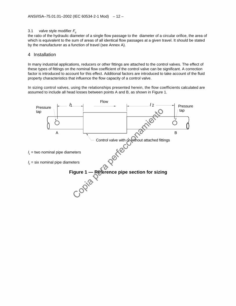
In sizing control valves, using the relationships presented herein, the flow coefficients calculated areassumed to include all head losses between points A and B, as shown in Figure 1.
Flow
Control valve with or without attached fittings
A
Pressuretap
l1
B
l 2 Pressuretap
l1 = two nominal pipe diameters
l2 = six nominal pipe diameters
Figure 1 — Reference pipe section for sizing
Copia
para
perfe
ccion
amien
to
Copia
para
perfe
ccion
amien
to
- 13 - ANSI/ISA-75.01.01-2002 (IEC 60534-2-1 Mod)
5 Symbols
Symbol Description Unit
C Flow coefficient (Kv, Cv) Various (see IEC 60534-1) (see note
4)
CiAssumed flow coefficient for iterative purposes Various (see IEC 60534-1) (see note
4)
d Nominal valve size mm (in)
D Internal diameter of the piping mm (in)
D1Internal diameter of upstream piping mm (in)
D2Internal diameter of downstream piping mm (in)
DoOrifice diameter mm (in)
FdValve style modifier (see Annex A) Dimensionless (see note 4)
FFLiquid critical pressure ratio factor Dimensionless
FLLiquid pressure recovery factor of a control valve without attached fittings Dimensionless (see note 4)
FLPCombined liquid pressure recovery factor and piping geometry factor of a controlvalve with attached fittings
Dimensionless (see note 4)
FPPiping geometry factor Dimensionless
FRReynolds number factor Dimensionless
FγSpecific heat ratio factor Dimensionless
GgGas specific gravity (ratio of density of flowing gas to density of air with both atstandard conditions, which is considered in this practice to be equal to the ratio ofthe molecular weight of gas to molecular weight of air
Dimensionless
M Molecular mass of flowing fluid kg/kg-mol (lb/lb-mol)
N Numerical constants (see Table 1) Various (see note 1)
P1Inlet absolute static pressure measured at point A (see Figure 1) kPa or bar (psia)(see note 2)
P2Outlet absolute static pressure measured at point B (see Figure 1) kPa or bar (psia)
PcAbsolute thermodynamic critical pressure kPa or bar (psia)
PrReduced pressure (P1 /Pc) Dimensionless
PvAbsolute vapor pressure of the liquid at inlet temperature kPa or bar (psia)
∆P Differential pressure between upstream and downstream pressure taps(P1 – P2)
kPa or bar (psi)
Q Volumetric flow rate (see note 5) m3/h (gpm, scfh)
RevValve Reynolds number Dimensionless
T1Inlet absolute temperature K (R)
TcAbsolute thermodynamic critical temperature K (R)
TrReduced temperature (T1 /Tc.) Dimensionless
ts Absolute reference temperature for standard cubic meter K (R)
W Mass flow rate kg/h (lbs/h)
x Ratio of pressure differential to inlet absolute pressure (∆P /P1) Dimensionless
xTPressure differential ratio factor of a control valve without attached fittings atchoked flow
Dimensionless (see note 4)
xTPPressure differential ratio factor of a control valve with attached fittings at chokedflow
Dimensionless (see note 4)
Y Expansion factor Dimensionless
Z Compressibility factor Dimensionless
v Kinematic viscosity m2/s (cS) (see note 3)
ρ1Density of fluid at P1 and T1 kg/m3 (lb/ft3)
ρ1/ρoRelative density (ρ1/ρo = 1.0 for water at 15°C) Dimensionless
γ Specific heat ratio Dimensionless
ζ Velocity head loss coefficient of a reducer, expander or other fitting attached to acontrol valve or valve trim
Dimensionless
Copia
para
perfe
ccion
amien
to
Copia
para
perfe
ccion
amien
to
ANSI/ISA–75.01.01–2002 (IEC 60534-2-1 Mod) – 14 –
ζ 1Upstream velocity head loss coefficient of fitting Dimensionless
ζ 2Downstream velocity head loss coefficient of fitting Dimensionless
ζ B1Inlet Bernoulli coefficient Dimensionless
ζ B2Outlet Bernoulli coefficient Dimensionless
NOTE 1 To determine the units for the numerical constants, dimensional analysis may be performed on the appropriate equations usingthe units given in Table 1.NOTE 2 1 bar = 102 kPa = 105 PaNOTE 3 1 centistoke = 10–6 m2/sNOTE 4 These values are travel-related and should be stated by the manufacturer.NOTE 5 Volumetric flow rates in cubic meters per hour, identified by the symbol Q, refer to standard conditions. The standard cubicmeter is taken at 1013.25 mbar and either 273 K or 288 K (see Table 1).
6 Sizing equations for incompressible fluids
The equations listed below identify the relationships between flow rates, flow coefficients, relatedinstallation factors, and pertinent service conditions for control valves handling incompressible fluids.Flow coefficients may be calculated using the appropriate equation selected from the ones given below.A sizing flow chart for incompressible fluids is given in Annex B.
6.1 Turbulent flow
The equations for the flow rate of a Newtonian liquid through a control valve when operating undernon-choked flow conditions are derived from the basic formula as given in IEC 60534-2-1.
6.1.1 Non-choked turbulent flow
6.1.1.1 Non-choked turbulent flow without attached fittings
( )[ ]vFL PFPFPifApplicable 12 −<∆
The flow coefficient shall be determined by
Eq. 1PN
QC
∆ρρ
= o1
1
/
NOTE 1 The numerical constant N1 depends on the units used in the general sizing equation and the type of flow coefficient:
Kv or Cv.
NOTE 2 An example of sizing a valve with non-choked turbulent flow without attached fittings is given in Annex F.
6.1.1.2 Non-choked turbulent flow with attached fittings
( ) ( )[ ]{ }vFpLP PFPFFPifApplicable / 12 −<∆
The flow coefficient shall be determined as follows:
Eq. 2PFN
QC o
∆ρρ
=/1
1 p
Copia
para
perfe
ccion
amien
to
Copia
para
perfe
ccion
amien
to

- 15 - ANSI/ISA-75.01.01-2002 (IEC 60534-2-1 Mod)
NOTE Refer to 8.1 for the piping geometry factor FP.
6.1.2 Choked turbulent flow
The maximum rate at which flow will pass through a control valve at choked flow conditions shall becalculated from the following equations:
6.1.2.1 Choked turbulent flow without attached fittings
( )[ ]vFL PFPFPifApplicable −≥∆ 12
The flow coefficient shall be determined as follows:
Eq. 3vF
o
L PFPFNQ
C−
ρρ=
1
1
1
/
NOTE An example of sizing a valve with choked flow without attached fittings is given in Annex F.
6.1.2.2 Choked turbulent flow with attached fittings
( ) ( )[ ]vFpLP PFPFFPifApplicable −≥∆ 12/
The following equation shall be used to calculate the flow coefficient:
Eq. 4vF
o
LP PFPFNQ
C−
ρρ=
1
1
1
/
6.2 Non-turbulent (laminar and transitional) flow
The equations for the flow rate of a Newtonian liquid through a control valve when operating under non-turbulent flow conditions are derived from the basic formula as given in IEC 60534-2-1. This equationis applicable if Rev < 10,000 (see Equation 28).
6.2.1 Non-turbulent flow without attached fittings
The flow coefficient shall be calculated as follows:
Eq. 5PFN
QC
∆ρρ
= o
R
/1
1
6.2.2 Non-turbulent flow with attached fittings
For non-turbulent flow, the effect of close-coupled reducers or other flow disturbing fittings is unknown.While there is no information on the laminar or transitional flow behavior of control valves installedbetween pipe reducers, the user of such valves is advised to utilize the appropriate equations for line-sizedvalves in the calculation of the FR factor. This should result in conservative flow coefficients sinceadditional turbulence created by reducers and expanders will further delay the onset of laminar flow.Therefore, it will tend to increase the respective FR factor for a given valve Reynolds number.
Copia
para
perfe
ccion
amien
to
Copia
para
perfe
ccion
amien
to
ANSI/ISA–75.01.01–2002 (IEC 60534-2-1 Mod) – 16 –
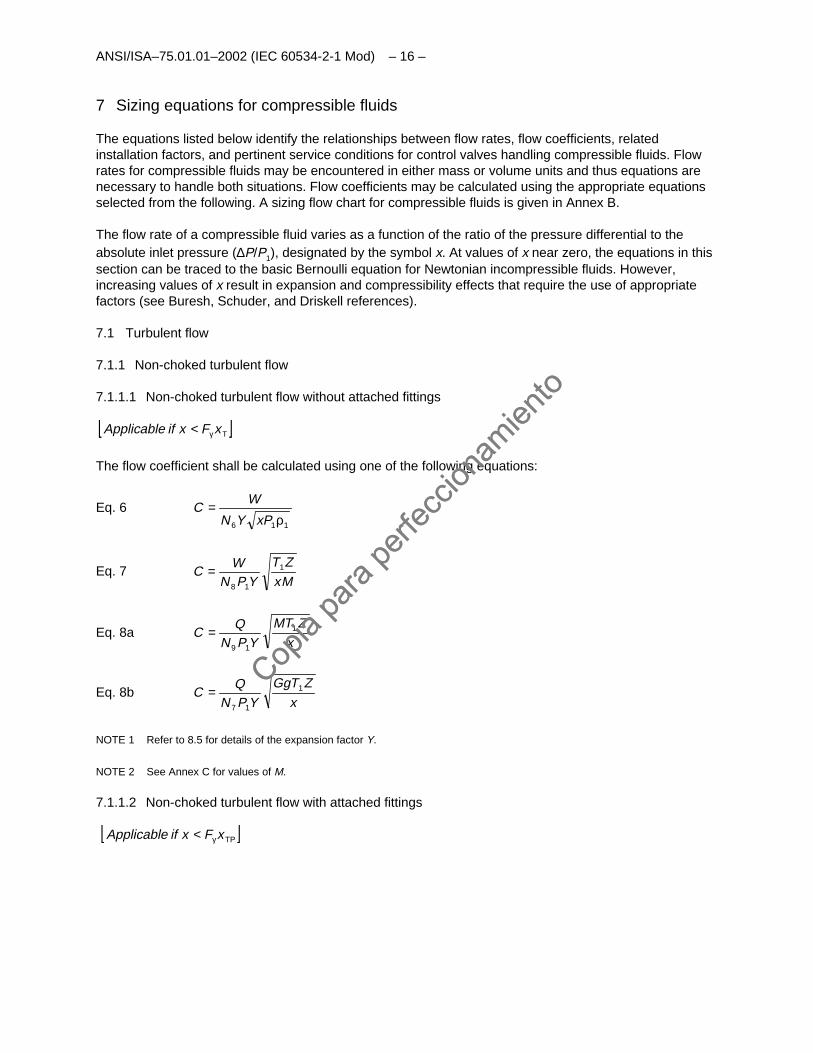
7 Sizing equations for compressible fluids
The equations listed below identify the relationships between flow rates, flow coefficients, relatedinstallation factors, and pertinent service conditions for control valves handling compressible fluids. Flowrates for compressible fluids may be encountered in either mass or volume units and thus equations arenecessary to handle both situations. Flow coefficients may be calculated using the appropriate equationsselected from the following. A sizing flow chart for compressible fluids is given in Annex B.
The flow rate of a compressible fluid varies as a function of the ratio of the pressure differential to theabsolute inlet pressure (∆P/P1), designated by the symbol x. At values of x near zero, the equations in thissection can be traced to the basic Bernoulli equation for Newtonian incompressible fluids. However,increasing values of x result in expansion and compressibility effects that require the use of appropriatefactors (see Buresh, Schuder, and Driskell references).
7.1 Turbulent flow
7.1.1 Non-choked turbulent flow
7.1.1.1 Non-choked turbulent flow without attached fittings
[ ]TxFxifApplicable γ<
The flow coefficient shall be calculated using one of the following equations:
Eq. 6116 ρ
=xPYN
WC
Eq. 7MxZT
YPNW
C 1
18
=
Eq. 8ax
ZTMYPN
QC 1
19
=
Eq. 8bx
ZTGgYPN
QC 1
17
=
NOTE 1 Refer to 8.5 for details of the expansion factor Y.
NOTE 2 See Annex C for values of M.
7.1.1.2 Non-choked turbulent flow with attached fittings
[ ]TPxFxifApplicable γ<
Copia
para
perfe
ccion
amien
to
Copia
para
perfe
ccion
amien
to
- 17 - ANSI/ISA-75.01.01-2002 (IEC 60534-2-1 Mod)
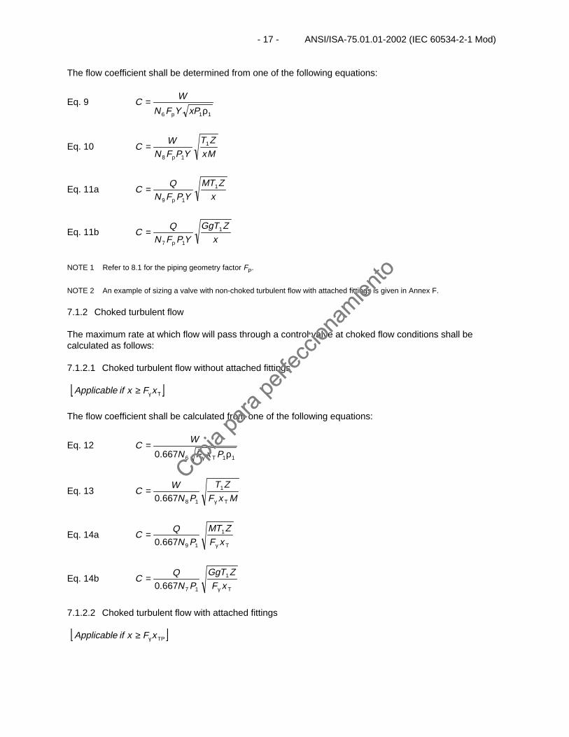
The flow coefficient shall be determined from one of the following equations:
Eq. 9116 ρ
=xPYFN
WC
p
Eq. 10Mx
ZT
YPFNW
C 1
18 p
=
Eq. 11ax
ZTM
YPFNQ
C 1
19 p
=
Eq. 11bx
ZTGg
YPFNQ
C 1
17 p
=
NOTE 1 Refer to 8.1 for the piping geometry factor FP.
NOTE 2 An example of sizing a valve with non-choked turbulent flow with attached fittings is given in Annex F.
7.1.2 Choked turbulent flow
The maximum rate at which flow will pass through a control valve at choked flow conditions shall becalculated as follows:
7.1.2.1 Choked turbulent flow without attached fittings
[ ]TxFxifApplicable γ≥
The flow coefficient shall be calculated from one of the following equations:
Eq. 12116667.0 ρ
=γ PxFN
WC
T
Eq. 13MxF
ZTPN
WC
Tγ
= 1
18667.0
Eq. 14aTxFZTM
PNQ
Cγ
= 1
19667.0
Eq. 14bTxFZTGg
PNQ
Cγ
= 1
17667.0
7.1.2.2 Choked turbulent flow with attached fittings
[ ]TPxFxifApplicable γ≥
Copia
para
perfe
ccion
amien
to
Copia
para
perfe
ccion
amien
to
ANSI/ISA–75.01.01–2002 (IEC 60534-2-1 Mod) – 18 –
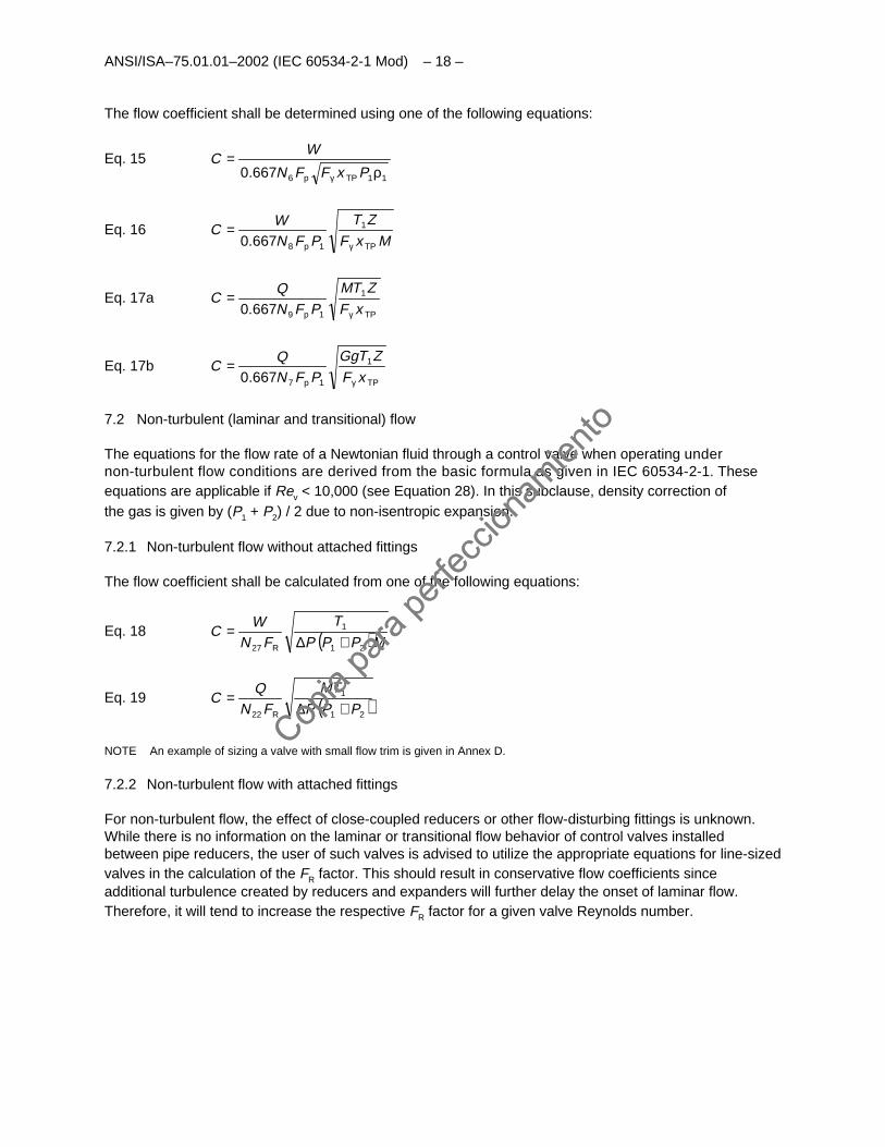
The flow coefficient shall be determined using one of the following equations:
Eq. 15116667.0 ρ
=γ PxFFN
WC
TPp
Eq. 16MxF
ZTPFN
WC
TPp γ
= 1
18667.0
Eq. 17aTPp xFZTM
PFNQ
Cγ
= 1
19667.0
Eq. 17bTPp xFZTGg
PFNQ
Cγ
= 1
17667.0
7.2 Non-turbulent (laminar and transitional) flow
The equations for the flow rate of a Newtonian fluid through a control valve when operating undernon-turbulent flow conditions are derived from the basic formula as given in IEC 60534-2-1. Theseequations are applicable if Rev < 10,000 (see Equation 28). In this subclause, density correction ofthe gas is given by (P1 + P2) / 2 due to non-isentropic expansion.
7.2.1 Non-turbulent flow without attached fittings
The flow coefficient shall be calculated from one of the following equations:
Eq. 18 ( )MPPP
T
FNW
C21
1
27 +∆=
R
Eq. 19 ( )21
1
22 PPP
TM
FNQ
C+∆
=R
NOTE An example of sizing a valve with small flow trim is given in Annex D.
7.2.2 Non-turbulent flow with attached fittings
For non-turbulent flow, the effect of close-coupled reducers or other flow-disturbing fittings is unknown.While there is no information on the laminar or transitional flow behavior of control valves installedbetween pipe reducers, the user of such valves is advised to utilize the appropriate equations for line-sizedvalves in the calculation of the FR factor. This should result in conservative flow coefficients sinceadditional turbulence created by reducers and expanders will further delay the onset of laminar flow.Therefore, it will tend to increase the respective FR factor for a given valve Reynolds number.
Copia
para
perfe
ccion
amien
to
Copia
para
perfe
ccion
amien
to
- 19 - ANSI/ISA-75.01.01-2002 (IEC 60534-2-1 Mod)
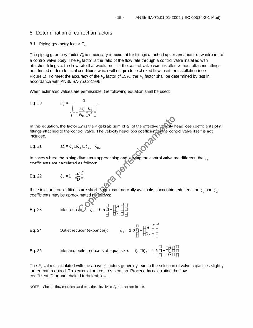
8 Determination of correction factors
8.1 Piping geometry factor FP
The piping geometry factor FP is necessary to account for fittings attached upstream and/or downstream toa control valve body. The FP factor is the ratio of the flow rate through a control valve installed withattached fittings to the flow rate that would result if the control valve was installed without attached fittingsand tested under identical conditions which will not produce choked flow in either installation (seeFigure 1). To meet the accuracy of the FP factor of ±5%, the FP factor shall be determined by test inaccordance with ANSI/ISA-75.02-1996.
When estimated values are permissible, the following equation shall be used:
Eq. 202
22
1
1
ζΣ+
=
d
CN
F
i
p
In this equation, the factor Σζ is the algebraic sum of all of the effective velocity head loss coefficients of allfittings attached to the control valve. The velocity head loss coefficient of the control valve itself is notincluded.
Eq. 21 2121 BB ζ−ζ+ζ+ζ=ζΣ
In cases where the piping diameters approaching and leaving the control valve are different, the ζ Bcoefficients are calculated as follows:
Eq. 224
1
−=ζDd
B
If the inlet and outlet fittings are short-length, commercially available, concentric reducers, the ζ 1 and ζ 2coefficients may be approximated as follows:
Eq. 23 Inlet reducer:
22
11 1 5.0
−=ζ
Dd
Eq. 24 Outlet reducer (expander):
22
22 1 0.1
−=ζ
Dd
Eq. 25 Inlet and outlet reducers of equal size:
22
21 1 5.1
−=ζ+ζDd
The FP values calculated with the above ζ factors generally lead to the selection of valve capacities slightlylarger than required. This calculation requires iteration. Proceed by calculating the flowcoefficient C for non-choked turbulent flow.
NOTE Choked flow equations and equations involving FP are not applicable.
Copia
para
perfe
ccion
amien
to
Copia
para
perfe
ccion
amien
to
ANSI/ISA–75.01.01–2002 (IEC 60534-2-1 Mod) – 20 –
Next, establish Ci as follows:
Eq. 26 CC 3.1=i
Using Ci from Equation 26, determine FP from Equation 20. If both ends of the valve are the same size, FP
may instead be determined from Figure 2. Then, determine if
Eq. 27 iCFC ≤
p
If the condition of Equation 27 is satisfied, then use the Ci established from Equation 26. If the condition ofEquation 27 is not met, then repeat the above procedure by again increasing Ci by 30%. This may requireseveral iterations until the condition required in Equation 27 is met. An iteration method more suitable forcomputers can be found in Annex B.
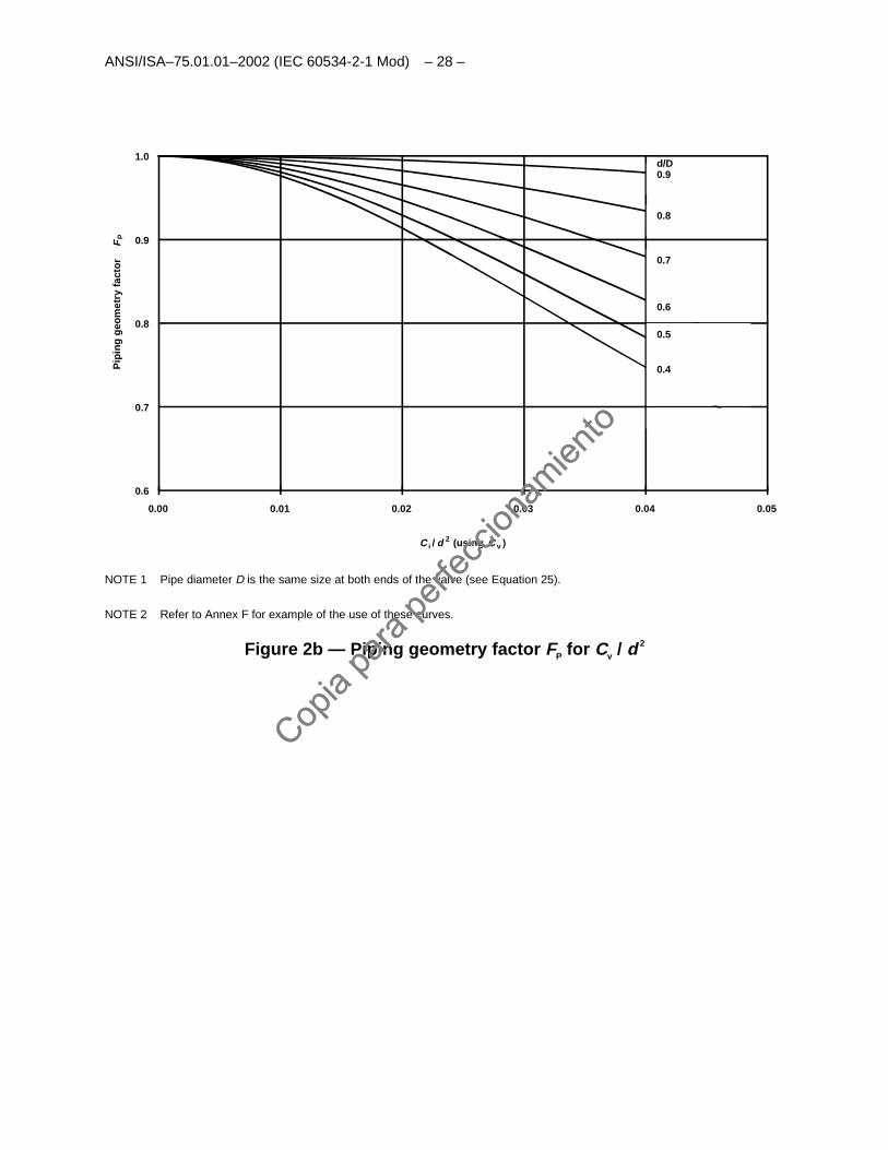
For graphical approximations of FP, refer to Figures 2a and 2b.
8.2 Reynolds number factor FR
The Reynolds number factor FR is required when non-turbulent flow conditions are established through acontrol valve because of a low pressure differential, a high viscosity, a very small flow coefficient, or acombination thereof.
The FR factor is determined by dividing the flow rate when non-turbulent flow conditions exist by the flowrate measured in the same installation under turbulent conditions.
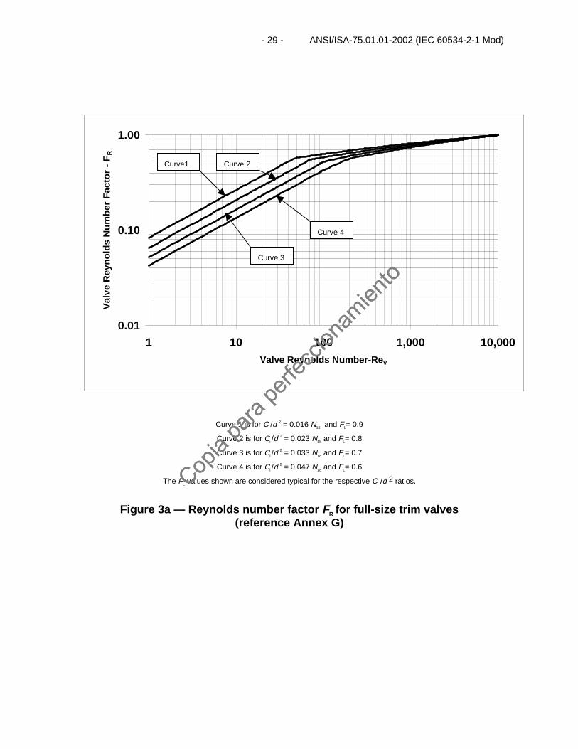
Tests show that FR can be determined from the curves given in Figure 3a or 3b using a valve Reynoldsnumber calculated from the following equation:
Eq. 28
4/1
42
224 1
+
ν=
DN
CF
FC
QFN iL
Li
dvRe
This calculation will require iteration. Proceed by calculating the flow coefficient C for turbulent flow. Thevalve style modifier Fd converts the geometry of the orifice(s) to an equivalent circular single flow passage.See Table 2 for typical values and Annex A for details. To meet a deviation of ±5% for Fd, the Fd factorshall be determined by test in accordance with IEC 60534-2-3.
NOTE Equations involving FP are not applicable.
Next, establish Ci as per Equation 26.
Apply Ci as per Equation 26 and determine FR. FR is determined from Figure 3a for full-size trim valves.
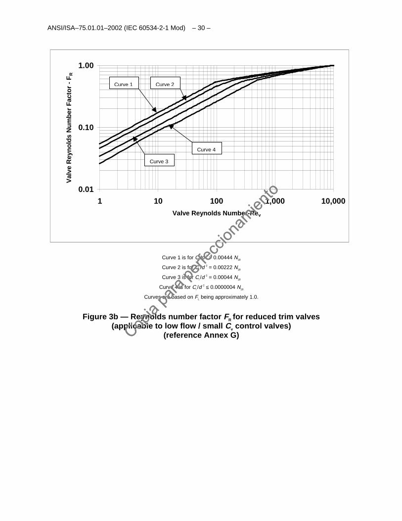
FR is determined from Figure 3b for reduced trim valves where Ci /d 2 at rated travel is less then 0.016 N18.
Eq. 29 iCFC ≤
R
Copia
para
perfe
ccion
amien
to
Copia
para
perfe
ccion
amien
to
- 21 - ANSI/ISA-75.01.01-2002 (IEC 60534-2-1 Mod)
If the condition of Equation 29 is satisfied, then use the Ci established from Equation 26. If the condition ofEquation 29 is not met, then repeat the above equation by again increasing Ci by 30 percent. This mayrequire several iterations until the conditions required in Equation 29 are met.
The equations defining nonturbulent flow for full size and reduced trim valves are stated in Annex G.
8.3 Liquid pressure recovery factors FL or FLP
8.3.1 Liquid pressure recovery factor without attached fittings FL
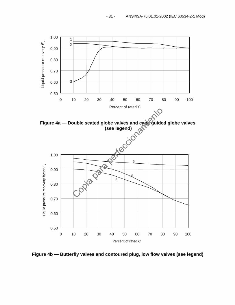
FL is the liquid pressure recovery factor of the valve without attached fittings. This factor accounts for theinfluence of the valve internal geometry on the valve capacity at choked flow. It is defined as the ratio ofthe actual maximum flow rate under choked flow conditions to a theoretical, non-choked flow rate whichwould be calculated if the pressure differential used was the difference between the valve inlet pressureand the apparent vena contracta pressure at choked flow conditions. The factor FL may be determinedfrom tests in accordance with ANSI/ISA-75.02-1996. Typical values of FL versus percent of rated flowcoefficient are shown in Figure 4.
8.3.2 Combined liquid pressure recovery factor and piping geometry factor with attached fittings FLP
FLP is the combined liquid pressure recovery factor and piping geometry factor for a control valve withattached fittings. It is obtained in the same manner as FL.
To meet a deviation of ±5% for FLP, FLP shall be determined by testing. When estimated values arepermissible, the following equation shall be used:
Eq. 30
( )2
212
2
1
ζΣ+
=
d
CN
F
FF
L
LLP
Here Σζ 1is the velocity head loss coefficient, ζ 1 + ζ B1, of the fitting attached upstream of the valve asmeasured between the upstream pressure tap and the control valve body inlet.
8.4 Liquid critical pressure ratio factor FF
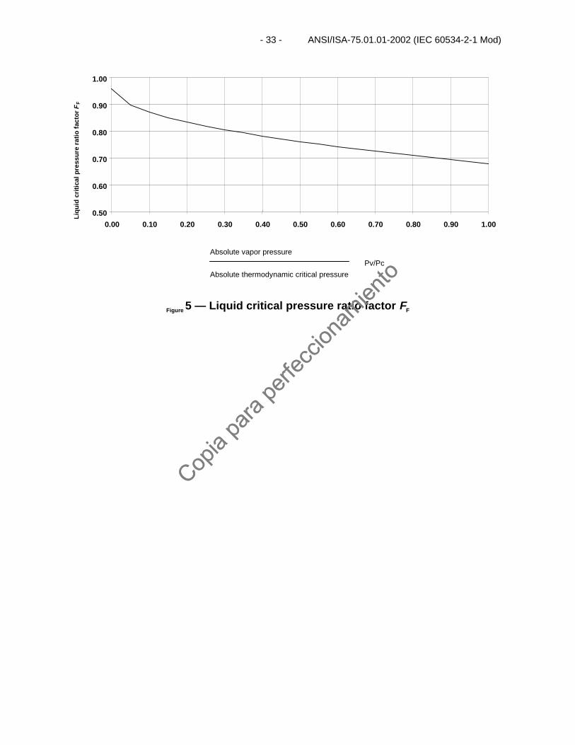
FF is the liquid critical pressure ratio factor. This factor is the ratio of the apparent vena contracta pressureat choked flow conditions to the vapor pressure of the liquid at inlet temperature. At vapor pressures nearzero, this factor is 0.96.
Values of FF may be determined from the curve in Figure 5 or approximated from the following equation:
Eq. 31c
vF P
PF 28.096.0 −=
Copia
para
perfe
ccion
amien
to
Copia
para
perfe
ccion
amien
to
ANSI/ISA–75.01.01–2002 (IEC 60534-2-1 Mod) – 22 –
8.5 Expansion factor Y
The expansion factor Y accounts for the change in density as the fluid passes from the valve inlet to thevena contracta (the location just downstream of the orifice where the jet stream area is a minimum). It alsoaccounts for the change in the vena contracta area as the pressure differential is varied.
Theoretically, Y is affected by all of the following:
a) ratio of port area to body inlet area;
b) shape of the flow path;
c) pressure differential ratio x ;
d) Reynolds number; and
e) specific heat ratio γ.
The influence of items a), b), c), and e) is accounted for by the pressure differential ratio factor xT, whichmay be established by air test and which is discussed in 8.6.1.
The Reynolds number is the ratio of inertial to viscous forces at the control valve orifice. In the case ofcompressible flow, its value is generally beyond the range of influence, except where the flow rate or theCv is very low or a combination of both exist (see 7.2 and 8.2).
The pressure differential ratio xT is influenced by the specific heat ratio of the fluid.
Y may be calculated using Equation 32.
Eq. 32TxF
xY
γ
−=3
1
The value of x for calculation purposes shall not exceed Fγ xT. If x > Fγ xT, then the flow becomes chokedand Y = 0.667. See 8.6 and 8.7 for information on x, xT and Fγ.
8.6 Pressure differential ratio factor xT or xTP
8.6.1 Pressure differential ratio factor without fittings xT
xT is the pressure differential ratio factor of a control valve installed without reducers or other fittings. If theinlet pressure P1 is held constant and the outlet pressure P2 is progressively lowered, the mass flow ratethrough a valve will increase to a maximum limit, a condition referred to as choked flow. Further reductionsin P2 will produce no further increase in flow rate.
This limit is reached when the pressure differential x reaches a value of Fγ xT. The limiting value of x isdefined as the critical differential pressure ratio. The value of x used in any of the sizing equations and inthe relationship for Y (Equation 32) shall be held to this limit even though the actual pressure differentialratio is greater. Thus, the numerical value of Y may range from 0.667, when x = Fγ xT, to 1.0 for very lowdifferential pressures.
Copia
para
perfe
ccion
amien
to
Copia
para
perfe
ccion
amien
to
- 23 - ANSI/ISA-75.01.01-2002 (IEC 60534-2-1 Mod)
The values of xT may be established by air test. The test procedure for this determination is covered inANSI/ISA-75.02-1996.
NOTE Representative values of xT for several types of control valves with full size trim and at full rated openings are given in
Table 2. Caution should be exercised in the use of this information. When precise values are required, they should be obtained by
test.
8.6.2 Pressure differential ratio factor with attached fittings xTP
If a control valve is installed with attached fittings, the value of xT will be affected.
To meet a deviation of ±5% for xTP, the valve and attached fittings shall be tested as a unit. Whenestimated values are permissible, the following equation shall be used:
Eq. 332
25
2
1
ζ+
=
d
CN
x
F
x
xiiT
p
T
TP
NOTE Values for N5 are given in Table 1.
In the above relationship, xT is the pressure differential ratio factor for a control valve installed withoutreducers or other fittings. ζ i is the sum of the inlet velocity head loss coefficients (ζ 1 + ζ B1) of the reduceror other fitting attached to the inlet face of the valve.
If the inlet fitting is a short-length, commercially available reducer, the value of ζ may be estimated usingEquation 23.
8.7 Specific heat ratio factor Fγ
The factor xT is based on air near atmospheric pressure as the flowing fluid with a specific heat ratio of1.40. If the specific heat ratio for the flowing fluid is not 1.40, the factor Fγ is used to adjust xT. Use thefollowing equation to calculate the specific heat ratio factor:
Eq. 3440.1γ=γF
NOTE See Annex C for values of γ and Fγ.
8.8 Compressibility factor Z
Several of the sizing equations do not contain a term for the actual density of the fluid at upstreamconditions. Instead, the density is inferred from the inlet pressure and temperature based on the laws ofideal gases. Under some conditions, real gas behavior can deviate markedly from the ideal. In thesecases, the compressibility factor Z shall be introduced to compensate for the discrepancy. Z is afunction of both the reduced pressure and reduced temperature (see appropriate reference books todetermine Z ). Reduced pressure Pr is defined as the ratio of the actual inlet absolute pressure to theabsolute thermodynamic critical pressure for the fluid in question. The reduced temperature Tr is definedsimilarly. That is
Copia
para
perfe
ccion
amien
to
Copia
para
perfe
ccion
amien
to
ANSI/ISA–75.01.01–2002 (IEC 60534-2-1 Mod) – 24 –
Eq. 35c
r PP
P 1=
Eq. 36c
r TT
T 1=
NOTE See Annex C for values of Pc and Tc.
Copia
para
perfe
ccion
amien
to
Copia
para
perfe
ccion
amien
to
- 25 - ANSI/ISA-75.01.01-2002 (IEC 60534-2-1 Mod)
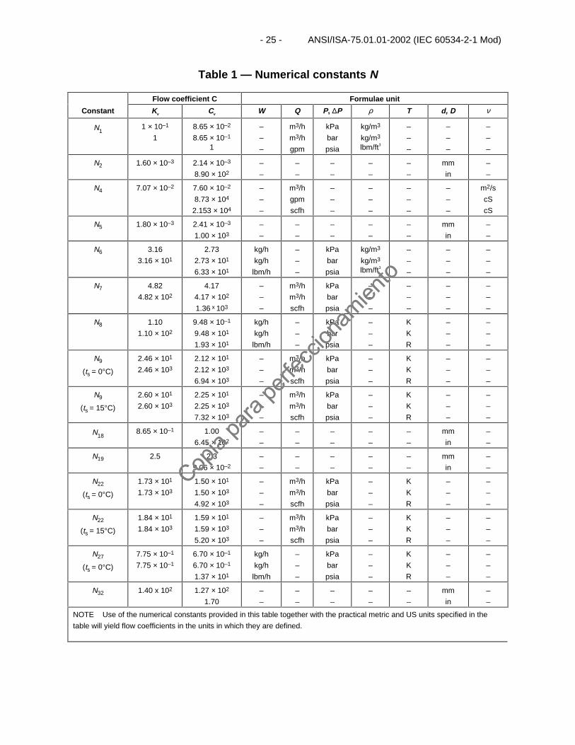
Table 1 — Numerical constants N
Flow coefficient C Formulae unit
Constant Kv Cv W Q P, ∆P ρ T d, D ν
N11 × 10–1
1
8.65 × 10⁻²
8.65 × 10⁻¹
1
–
–
–
m3/h
m3/h
gpm
kPa
bar
psia
kg/m3
kg/m3
lbm/ft3
–
–
–
–
–
–
–
–
–
N2 1.60 × 10⁻³ 2.14 × 10⁻³
8.90 × 10²
–
–
–
–
–
–
–
–
–
–
mm
in
–
–
N4 7.07 × 10⁻² 7.60 × 10⁻²
8.73 × 10⁴
2.153 × 10⁴
–
–
–
m3/h
gpm
scfh
–
–
–
–
–
–
–
–
–
–
–
–
m2/s
cS
cS
N5 1.80 × 10⁻³ 2.41 × 10⁻³
1.00 × 10³
–
–
–
–
–
–
–
–
–
–
mm
in
–
–
N6 3.16
3.16 × 101
2.73
2.73 × 101
6.33 × 101
kg/h
kg/h
lbm/h
–
–
–
kPa
bar
psia
kg/m3
kg/m3
lbm/ft3
–
–
–
–
–
–
–
–
–
N7 4.82
4.82 x 10²
4.17
4.17 × 10²
1.36 x 10³
–
–
–
m3/h
m3/h
scfh
kPa
bar
psia
–
–
–
–
–
–
–
–
–
–
–
–
N8 1.10
1.10 × 10²
9.48 × 10⁻¹
9.48 × 101
1.93 × 101
kg/h
kg/h
lbm/h
–
–
–
kPa
bar
psia
–
–
–
K
K
R
–
–
–
–
–
–
N9
(ts = 0°C)
2.46 × 101
2.46 × 10³
2.12 × 101
2.12 × 10³
6.94 × 10³
–
–
–
m3/h
m3/h
scfh
kPa
bar
psia
–
–
–
K
K
R
–
–
–
–
–
–
N9
(ts = 15°C)
2.60 × 101
2.60 × 10³
2.25 × 101
2.25 × 10³
7.32 × 10³
–
–
–
m3/h
m3/h
scfh
kPa
bar
psia
–
–
–
K
K
R
–
–
–
–
–
–
N188.65 × 10–1 1.00
6.45 × 10²
–
–
–
–
–
–
–
–
–
–
mm
in
–
–
N19 2.5 2.3
9.06 × 10⁻²
–
–
–
–
–
–
–
–
–
–
mm
in
–
–
N22
(ts = 0°C)
1.73 × 101
1.73 × 10³
1.50 × 101
1.50 × 10³
4.92 × 10³
–
–
–
m3/h
m3/h
scfh
kPa
bar
psia
–
–
–
K
K
R
–
–
–
–
–
–
N22
(ts = 15°C)
1.84 × 101
1.84 × 10³
1.59 × 101
1.59 × 10³
5.20 × 10³
–
–
–
m3/h
m3/h
scfh
kPa
bar
psia
–
–
–
K
K
R
–
–
–
–
–
–
N27
(ts = 0°C)
7.75 × 10⁻¹
7.75 × 10⁻¹
6.70 × 10⁻¹
6.70 × 10⁻¹
1.37 × 101
kg/h
kg/h
lbm/h
–
–
–
kPa
bar
psia
–
–
–
K
K
R
–
–
–
–
–
–
N32 1.40 x 10² 1.27 × 10²
1.70
–
–
–
–
–
–
–
–
–
–
mm
in
–
–
NOTE Use of the numerical constants provided in this table together with the practical metric and US units specified in the
table will yield flow coefficients in the units in which they are defined.
Copia
para
perfe
ccion
amien
to
Copia
para
perfe
ccion
amien
to
ANSI/ISA–75.01.01–2002 (IEC 60534-2-1 Mod) – 26 –
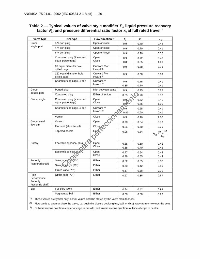
Table 2 — Typical values of valve style modifier Fd, liquid pressure recoveryfactor FL, and pressure differential ratio factor xT at full rated travel 1)
Valve type Trim type Flow direction 2) FL xT Fd
3 V-port plug Open or close 0.9 0.70 0.48
4 V-port plug Open or close 0.9 0.70 0.41
6 V-port plug Open or close 0.9 0.70 0.30
Contoured plug (linear andequal percentage)
OpenClose
0.9
0.8
0.72
0.55
0.46
1.00
60 equal diameter holedrilled cage
Outward 3) orinward 3)
0.9 0.68 0.13
120 equal diameter holedrilled cage
Outward 3) orinward 3)
0.9 0.68 0.09
Globe,single port
Characterized cage, 4-port Outward 3)
Inward 3)0.9
0.85
0.75
0.70
0.41
0.41
Ported plug Inlet between seats 0.9 0.75 0.28Globe,double port
Contoured plug Either direction 0.85 0.70 0.32
Contoured plug (linear andequal percentage)
OpenClose
0.9
0.8
0.72
0.65
0.46
1.00
Characterized cage, 4-port Outward 3)
Inward 3)0.9
0.85
0.65
0.60
0.41
0.41
Globe, angle
Venturi Close 0.5 0.20 1.00
V-notch Open 0.98 0.84 0.70
Flat seat (short travel) Close 0.85 0.70 0.30
Globe, smallflow trim
Tapered needle Open 0.95 0.84
o
5.0L
19)(
DCF
N
Eccentric spherical plug OpenClose
0.85
0.68
0.60
0.40
0.42
0.42
Rotary
Eccentric conical plug OpenClose
0.77
0.79
0.54
0.55
0.44
0.44
Swing-through (70°) Either 0.62 0.35 0.57
Swing-through (60°) Either 0.70 0.42 0.50
Butterfly(centered shaft)
Fluted vane (70°) Either 0.67 0.38 0.30
HighPerformanceButterfly(eccentric shaft)
Offset seat (70°) Either 0.67 0.35 0.57
Full bore (70°) Either 0.74 0.42 0.99Ball
Segmented ball Either 0.60 0.30 0.98
1) These values are typical only; actual values shall be stated by the valve manufacturer.
2) Flow tends to open or close the valve, i.e. push the closure device (plug, ball, or disc) away from or towards the seat.
3) Outward means flow from center of cage to outside, and inward means flow from outside of cage to center.
Copia
para
perfe
ccion
amien
to
Copia
para
perfe
ccion
amien
to
- 27 - ANSI/ISA-75.01.01-2002 (IEC 60534-2-1 Mod)
0.00 0.01 0.02 0.03 0.04 0.05
C i / d 2 (using K v)
Pip
ing
geo
met
ry f
acto
r FP
d/D
0.9
0.8
0.7
0.6
0.4
0.5
0.6
0.7
0.8
0.9
1.0
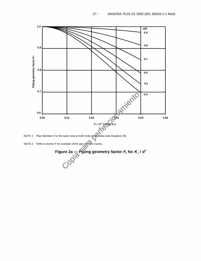
NOTE 1 Pipe diameter D is the same size at both ends of the valve (see Equation 25).
NOTE 2 Refer to Annex F for example of the use of these curves.
Figure 2a — Piping geometry factor FP for K v / d
2
Copia
para
perfe
ccion
amien
to
Copia
para
perfe
ccion
amien
to
ANSI/ISA–75.01.01–2002 (IEC 60534-2-1 Mod) – 28 –
0.6
0.7
0.8
0.9
1.0
0.00 0.01 0.02 0.03 0.04 0.05
C i / d 2 (using C v )
Pip
ing
geo
met
ry f
acto
rF
P
0.9
0.8
0.7
0.6
0.5
0.4
d/D
NOTE 1 Pipe diameter D is the same size at both ends of the valve (see Equation 25).
NOTE 2 Refer to Annex F for example of the use of these curves.
Figure 2b — Piping geometry factor FP for Cv / d
2
Copia
para
perfe
ccion
amien
to
Copia
para
perfe
ccion
amien
to
- 29 - ANSI/ISA-75.01.01-2002 (IEC 60534-2-1 Mod)
Curve 1 is for Ci /d 2 = 0.016 N18 and FL= 0.9
Curve 2 is for Ci /d 2 = 0.023 N18 and FL= 0.8
Curve 3 is for Ci /d 2 = 0.033 N18 and FL= 0.7
Curve 4 is for Ci /d 2 = 0.047 N18 and FL= 0.6
The FL values shown are considered typical for the respective Ci /d 2 ratios.
Figure 3a — Reynolds number factor FR for full-size trim valves(reference Annex G)
0.01
0.10
1.00
1 10 100 1,000 10,000Valve Reynolds Number-Rev
Val
ve R
eyn
old
s N
um
ber
Fac
tor
- F
R
Curve1 Curve 2
Curve 3
Curve 4
Copia
para
perfe
ccion
amien
to
Copia
para
perfe
ccion
amien
to
ANSI/ISA–75.01.01–2002 (IEC 60534-2-1 Mod) – 30 –
0.01
0.10
1.00
1 10 100 1,000 10,000Valve Reynolds Number-Rev
Val
ve R
eyn
old
s N
um
ber
Fac
tor
- F
R
Curve 1 is for Ci /d 2 = 0.00444 N18
Curve 2 is for Ci /d 2 = 0.00222 N18
Curve 3 is for Ci /d 2 = 0.00044 N18
Curve 4 is for Ci /d 2 ≤ 0.0000004 N18
Curves are based on FL being approximately 1.0.
Figure 3b — Reynolds number factor FR for reduced trim valves(applicable to low flow / small Cv control valves)
(reference Annex G)
Curve 1 Curve 2
Curve 3
Curve 4
Copia
para
perfe
ccion
amien
to
Copia
para
perfe
ccion
amien
to
- 31 - ANSI/ISA-75.01.01-2002 (IEC 60534-2-1 Mod)
0.50
0.60
0.70
0.80
0.90
1.00
0 10 20 30 40 50 60 70 80 90 100
Percent of rated C
Liqu
id p
ress
ure
reco
very
FL
12
3
Figure 4a — Double seated globe valves and cage guided globe valves (see legend)
0.50
0.60
0.70
0.80
0.90
1.00
0 10 20 30 40 50 60 70 80 90 100
Percent of rated C
Liqu
id p
ress
ure
reco
very
fact
or F
L
45
6
Figure 4b — Butterfly valves and contoured plug, low flow valves (see legend)
Copia
para
perfe
ccion
amien
to
Copia
para
perfe
ccion
amien
to
ANSI/ISA–75.01.01–2002 (IEC 60534-2-1 Mod) – 32 –
0.50
0.60
0.70
0.80
0.90
1.00
0 10 20 30 40 50 60 70 80 90 100
Percent of rated C
Liqu
id p
ress
ure
reco
very
fact
orF
L9
10
8
11
7
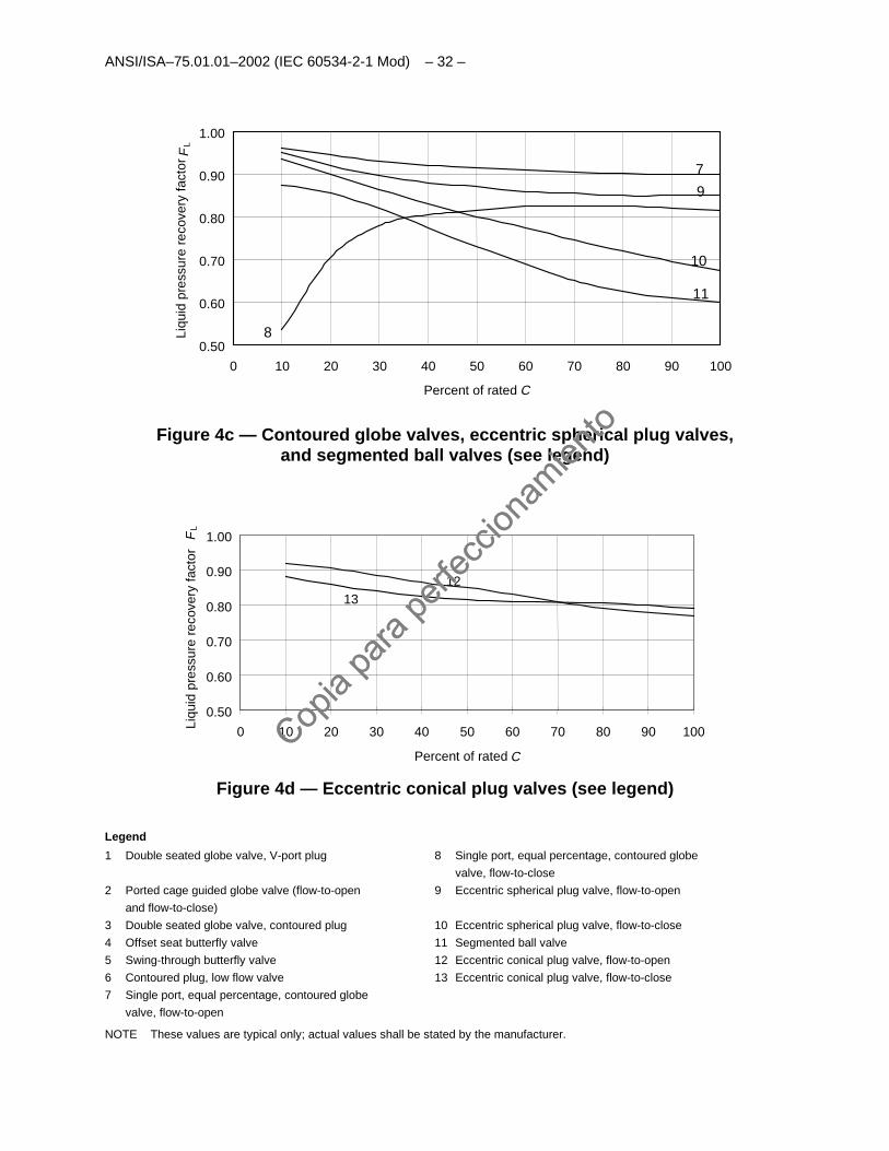
Figure 4c — Contoured globe valves, eccentric spherical plug valves,and segmented ball valves (see legend)
0.50
0.60
0.70
0.80
0.90
1.00
0 10 20 30 40 50 60 70 80 90 100
Percent of rated C
Liqu
id p
ress
ure
reco
very
fact
orF
L
1213
Figure 4d — Eccentric conical plug valves (see legend)
Legend
1 Double seated globe valve, V-port plug 8 Single port, equal percentage, contoured globe
valve, flow-to-close
2 Ported cage guided globe valve (flow-to-open
and flow-to-close)
9 Eccentric spherical plug valve, flow-to-open
3 Double seated globe valve, contoured plug 10 Eccentric spherical plug valve, flow-to-close
4 Offset seat butterfly valve 11 Segmented ball valve
5 Swing-through butterfly valve 12 Eccentric conical plug valve, flow-to-open
6 Contoured plug, low flow valve 13 Eccentric conical plug valve, flow-to-close
7 Single port, equal percentage, contoured globe
valve, flow-to-open
NOTE These values are typical only; actual values shall be stated by the manufacturer.
Copia
para
perfe
ccion
amien
to
Copia
para
perfe
ccion
amien
to
- 33 - ANSI/ISA-75.01.01-2002 (IEC 60534-2-1 Mod)
0.50
0.60
0.70
0.80
0.90
1.00
0.00 0.10 0.20 0.30 0.40 0.50 0.60 0.70 0.80 0.90 1.00
Liq
uid
cri
tica
l pre
ssu
re r
atio
fac
torF
F
Figure 5 — Liquid critical pressure ratio factor FF
Absolute vapor pressure
Pv/Pc
Absolute thermodynamic critical pressure
Copia
para
perfe
ccion
amien
to
Copia
para
perfe
ccion
amien
to

This page intentionally left blank.
Copia
para
perfe
ccion
amien
to
Copia
para
perfe
ccion
amien
to
- 35 - ANSI/ISA-75.01.01-2002 (IEC 60534-2-1 Mod)
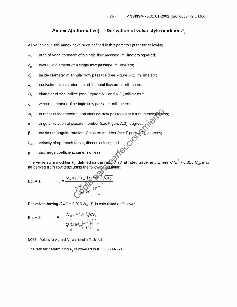
Annex A(informative) — Derivation of valve style modifier Fd
All variables in this annex have been defined in this part except for the following:
Ao area of vena contracta of a single flow passage, millimeters squared;
dH hydraulic diameter of a single flow passage, millimeters;
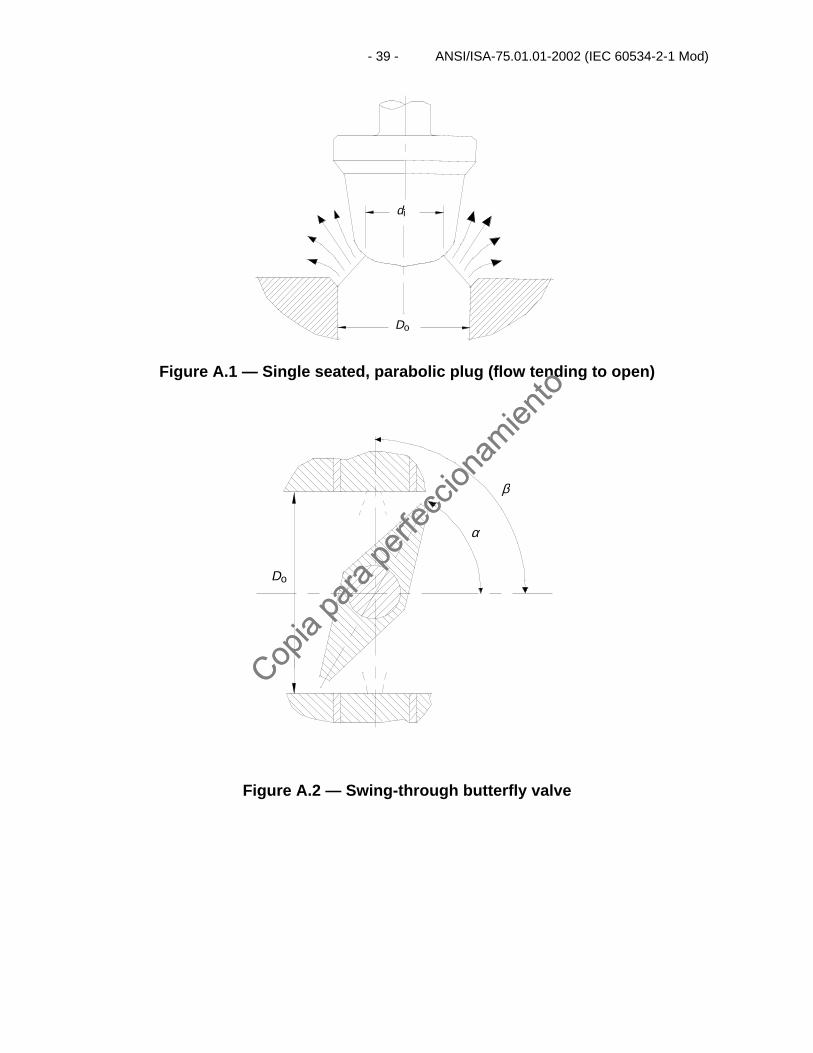
di inside diameter of annular flow passage (see Figure A.1), millimeters;
do equivalent circular diameter of the total flow area, millimeters;
Do diameter of seat orifice (see Figures A.1 and A.2), millimeters;
lw wetted perimeter of a single flow passage, millimeters;
No number of independent and identical flow passages of a trim, dimensionless;
α angular rotation of closure member (see Figure A.2), degrees;
β maximum angular rotation of closure member (see Figure A.2), degrees;
ζ B1 velocity of approach factor, dimensionless; and
µ discharge coefficient, dimensionless.
The valve style modifier Fd, defined as the ratio dH /do at rated travel and where Ci /d 2 > 0.016 N18, may
be derived from flow tests using the following equation:
Eq. A.1( )
4/1
42
22
222226
1
/
+
ν=
DN
CFQ
FCdCFFNF
L
LRLd
For valves having Ci /d 2 ≤ 0.016 N18, Fd is calculated as follows:
Eq. A.2
+
ν=
3/2
232
2231
1d
CNQ
FCFFNF LRL
d
NOTE Values for N26 and N32 are listed in Table A.1.
The test for determining Fd is covered in IEC 60534-2-3.
Copia
para
perfe
ccion
amien
to
Copia
para
perfe
ccion
amien
to
ANSI/ISA–75.01.01–2002 (IEC 60534-2-1 Mod) – 36 –
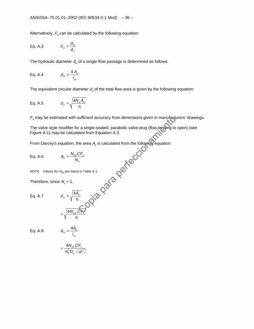
Alternatively, Fd can be calculated by the following equation:
Eq. A.3o
Hd d
dF =
The hydraulic diameter dH of a single flow passage is determined as follows:
Eq. A.4w
oH l
Ad
4=
The equivalent circular diameter do of the total flow area is given by the following equation:
Eq. A.5π
= ooo
ANd
4
Fd may be estimated with sufficient accuracy from dimensions given in manufacturers’ drawings.
The valve style modifier for a single-seated, parabolic valve plug (flow tending to open) (seeFigure A.1) may be calculated from Equation A.3.
From Darcey's equation, the area Ao is calculated from the following equation:
Eq. A.6o
Lo N
FCNA 23=
NOTE Values for N23 are listed in Table A.1.
Therefore, since No = 1,
Eq. A.7π
= oo
Ad
4
π= LFCN234
Eq. A.8w
oH l
Ad
4=
( )io
L
dDFCN
+π= 234
Copia
para
perfe
ccion
amien
to
Copia
para
perfe
ccion
amien
to
- 37 - ANSI/ISA-75.01.01-2002 (IEC 60534-2-1 Mod)
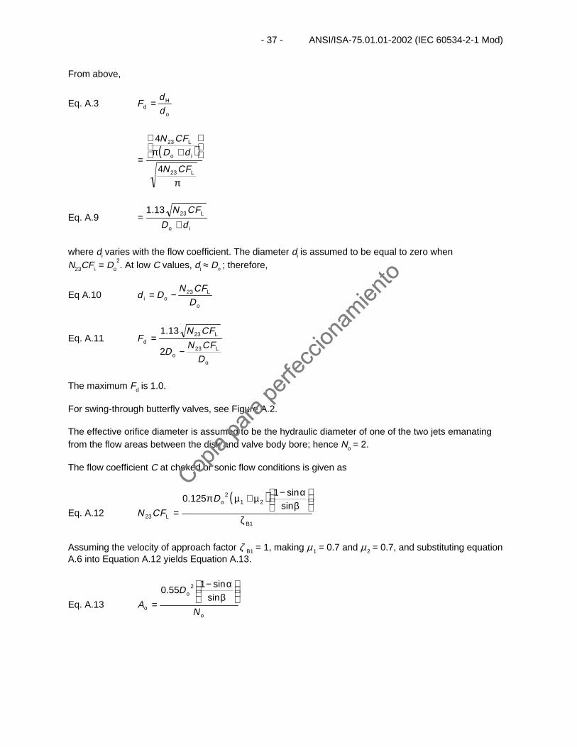
From above,
Eq. A.3o
Hd d
dF =
( )
π
+π
=L
io
L
FCN
dDFCN
23
23
4
4
Eq. A.9io
L
dD
FCN
+= 2313.1
where di varies with the flow coefficient. The diameter di is assumed to be equal to zero whenN23CFL = Do
2. At low C values, di ≈ Do ; therefore,
Eq A.10o
Loi D
FCNDd 23−=
Eq. A.11
o
Lo
Ld
D
FCND
FCNF
23
23
2
13.1
−=
The maximum Fd is 1.0.
For swing-through butterfly valves, see Figure A.2.
The effective orifice diameter is assumed to be the hydraulic diameter of one of the two jets emanatingfrom the flow areas between the disk and valve body bore; hence No = 2.
The flow coefficient C at choked or sonic flow conditions is given as
Eq. A.12
( )
1
212
23
sinsin1
125.0
B
o
L ζ
β
α−µ+µπ=
D
FCN
Assuming the velocity of approach factor ζ B1 = 1, making µ 1 = 0.7 and µ 2 = 0.7, and substituting equationA.6 into Equation A.12 yields Equation A.13.
Eq. A.13o
o
o N
D
A
β
α−
=sin
sin155.0 2
Copia
para
perfe
ccion
amien
to
Copia
para
perfe
ccion
amien
to
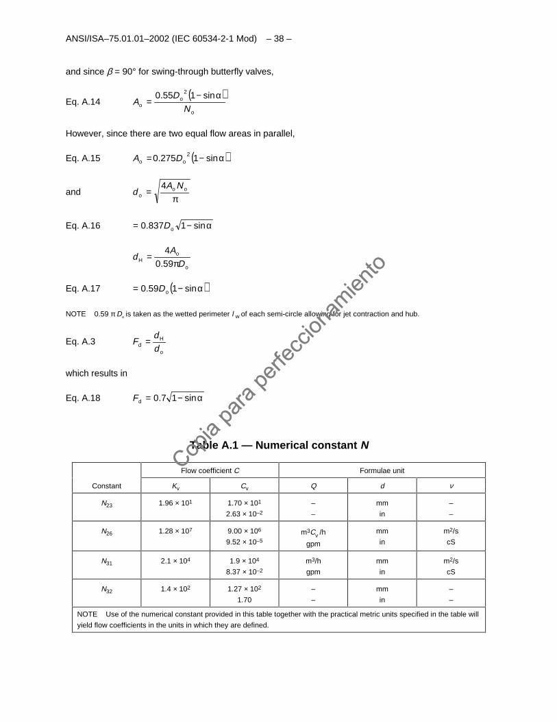
ANSI/ISA–75.01.01–2002 (IEC 60534-2-1 Mod) – 38 –
and since β = 90° for swing-through butterfly valves,
Eq. A.14( )o
oo N
DA
α−=
sin155.0 2
However, since there are two equal flow areas in parallel,
Eq. A.15 ( )α−= sin1275.0 2oo DA
andπ
= ooo
NAd
4
Eq. A.16 α−= sin1837.0 oD
o
oH D
Ad
π=
59.0
4
Eq. A.17 ( )α−= sin159.0 oD
NOTE 0.59 π Do is taken as the wetted perimeter l w of each semi-circle allowing for jet contraction and hub.
Eq. A.3o
Hd d
dF =
which results in
Eq. A.18 α−= sin17.0dF
Table A.1 — Numerical constant N
Flow coefficient C Formulae unit
Constant Kv Cv Q d ν
N23 1.96 × 101 1.70 × 101
2.63 × 10⁻²
–
–
mm
in
–
–
N26 1.28 × 10⁷ 9.00 × 10⁶
9.52 × 10⁻⁵
m3Cv /h
gpm
mm
in
m2/s
cS
N31 2.1 × 10⁴ 1.9 × 10⁴
8.37 × 10⁻²
m3/h
gpm
mm
in
m2/s
cS
N32 1.4 × 10² 1.27 × 10²
1.70
–
–
mm
in
–
–
NOTE Use of the numerical constant provided in this table together with the practical metric units specified in the table will
yield flow coefficients in the units in which they are defined.
Copia
para
perfe
ccion
amien
to
Copia
para
perfe
ccion
amien
to
- 39 - ANSI/ISA-75.01.01-2002 (IEC 60534-2-1 Mod)
Do
di
Figure A.1 — Single seated, parabolic plug (flow tending to open)
Do
β
α
Figure A.2 — Swing-through butterfly valve
Copia
para
perfe
ccion
amien
to
Copia
para
perfe
ccion
amien
to

This page intentionally left blank.
Copia
para
perfe
ccion
amien
to
Copia
para
perfe
ccion
amien
to
- 41 - ANSI/ISA-75.01.01-2002 (IEC 60534-2-1 Mod)
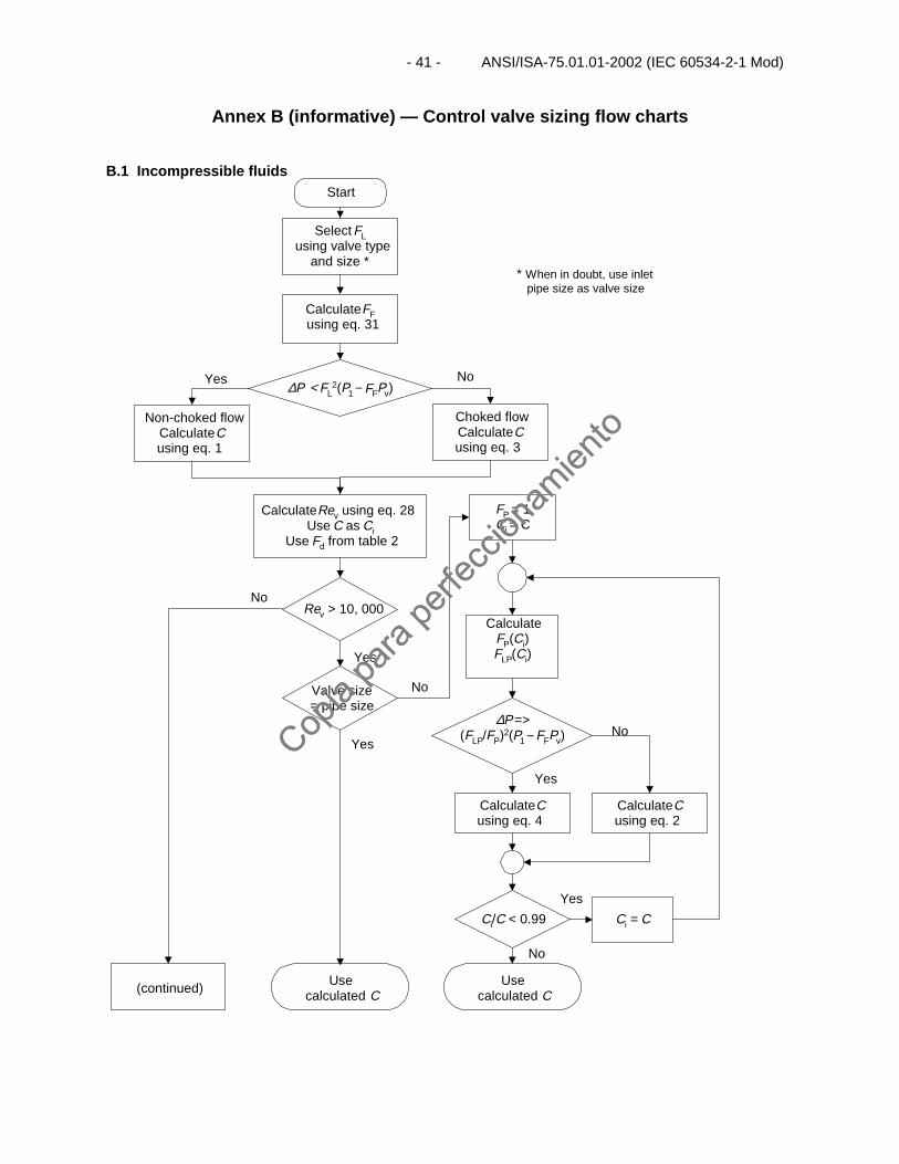
Annex B (informative) — Control valve sizing flow charts
Start
SelectFLusing valve type
and size *
CalculateFFusing eq. 31
∆P < FL2(P1− FFPv)
Non-choked flowCalculateCusing eq. 1
Choked flowCalculateCusing eq. 3
CalculateRev using eq. 28Use C as Ci
Use Fd from table 2
Rev > 10, 000
Valve size= pipe size
Usecalculated C
FP = 1Ci = C
CalculateFP(Ci)FLP(Ci)
∆P =>(FLP/FP)2(P1 − FFPv)
CalculateCusing eq. 4
Ci/C < 0.99
Usecalculated C
Ci = C
CalculateCusing eq. 2
Yes No
Yes
Yes
No
No
Yes
* When in doubt, use inletpipe size as valve size
B.1 Incompressible fluids
Yes
No
(continued)
No
Copia
para
perfe
ccion
amien
to
Copia
para
perfe
ccion
amien
to
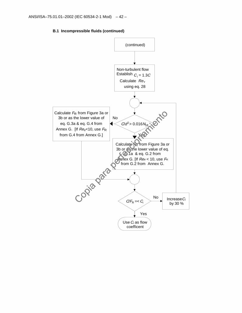
ANSI/ISA–75.01.01–2002 (IEC 60534-2-1 Mod) – 42 –
Non-turbulent flow Establish C i = 1.3 C
Calculate Rev
using eq. 28
C/d2 > 0.016N18
Calculate FR from Figure 3a or3b or as the lower value of
eq. G.3a & eq. G.4 from
from G.4 from Annex G.]
C/FR =< Ci
Use C as flowcoefficent
No
Yes
IncreaseCi
i
by 30 %
No
Yes
B.1 Incompressible fluids (continued)
(continued)
Calculate FR from Figure 3a or3b or as the lower value of eq.
G.1a & eq. G.2 fromAnnex G. [If Rev < 10, use FR
from G.2 from Annex G.
Annex G. [If Rev<10, use FR
Copia
para
perfe
ccion
amien
to
Copia
para
perfe
ccion
amien
to
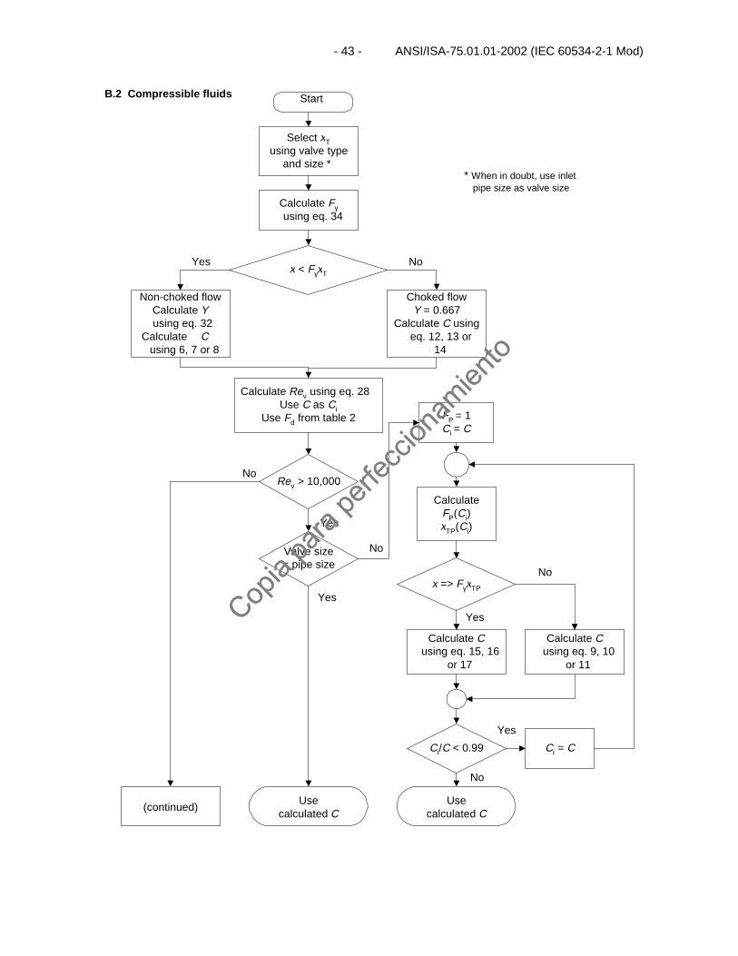
- 43 - ANSI/ISA-75.01.01-2002 (IEC 60534-2-1 Mod)
Start
Select xTusing valve type
and size *
Calculate Fγusing eq. 34
x < FγxT
Non-choked flowCalculate Yusing eq. 32
Calculate Cusing 6, 7 or 8
Choked flowY = 0.667
Calculate C usingeq. 12, 13 or
14
Calculate Rev using eq. 28Use C as Ci
Use Fd from table 2
Rev > 10,000
Valve size= pipe size
Usecalculated C
FP = 1Ci = C
CalculateFP(Ci)xTP(Ci)
x => FγxTP
Calculate Cusing eq. 15, 16
or 17
Ci/C < 0.99
Usecalculated C
Ci = C
Calculate Cusing eq. 9, 10
or 11
Yes No
No
Yes
Yes
No
No
Yes
* When in doubt, use inletpipe size as valve size
B.2 Compressible fluids
Yes
No
(continued)
Copia
para
perfe
ccion
amien
to
Copia
para
perfe
ccion
amien
to
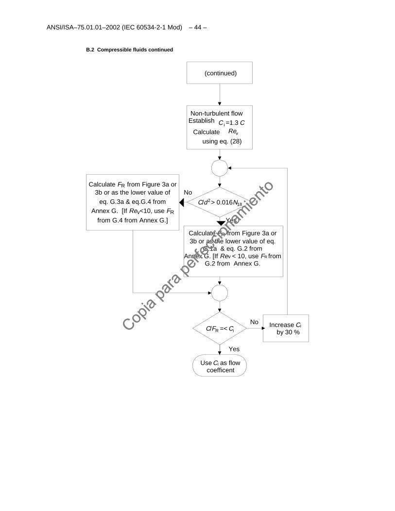
ANSI/ISA–75.01.01–2002 (IEC 60534-2-1 Mod) – 44 –
Non-turbulent flowEstablish C i =1.3 C
Calculate Rev
using eq. (28)
C/d2 > 0.016N18
Calculate FR from Figure 3a or3b or as the lower value of
eq. G.3a & eq.G.4 from
from G.4 from Annex G.]
C/FR =< Ci
Use C as flowcoefficent
No
Yes
Increase Ci
i
by 30 %
No
Yes
B.2 Compressible fluids continued
(continued)
Calculate FR from Figure 3a or3b or as the lower value of eq.
G.1a & eq. G.2 fromAnnex G. [If Rev < 10, use FR from
G.2 from Annex G.
Annex G. [If Rev<10, use FR
Copia
para
perfe
ccion
amien
to
Copia
para
perfe
ccion
amien
to
- 45 - ANSI/ISA-75.01.01-2002 (IEC 60534-2-1 Mod)
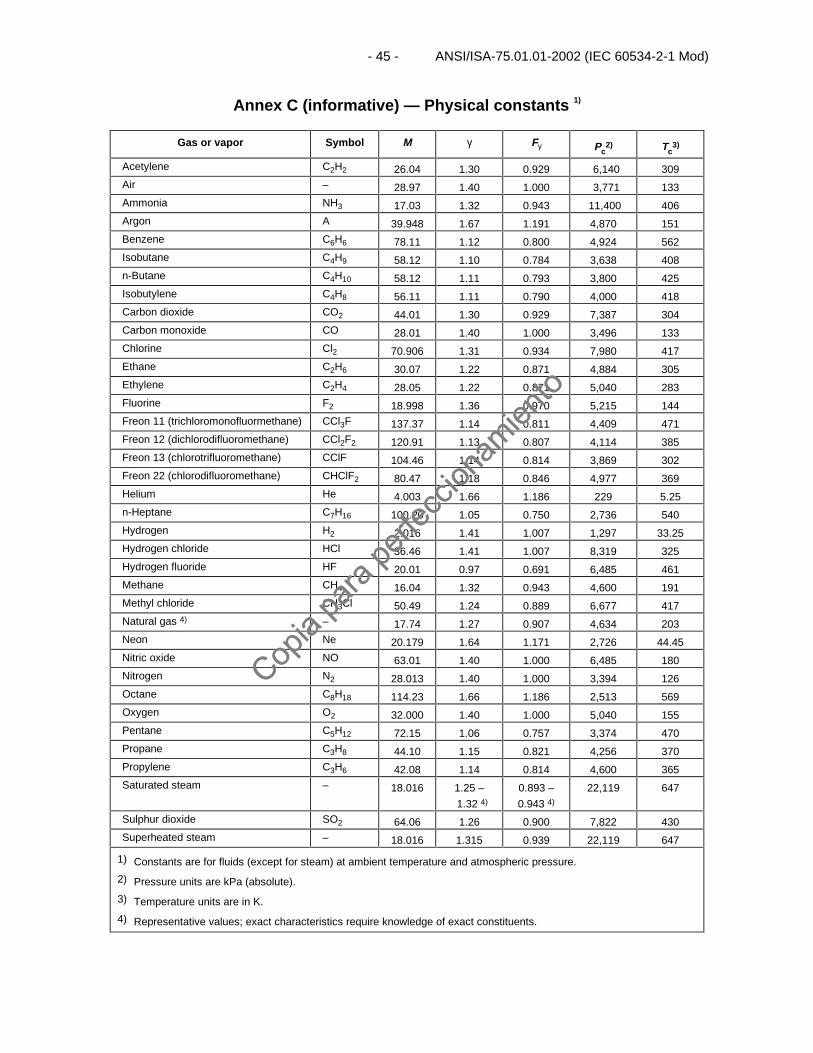
Annex C (informative) — Physical constants 1)
Gas or vapor Symbol M γ Fγ Pc2) Tc
3)
Acetylene C2H2 26.04 1.30 0.929 6,140 309Air – 28.97 1.40 1.000 3,771 133Ammonia NH3 17.03 1.32 0.943 11,400 406Argon A 39.948 1.67 1.191 4,870 151Benzene C6H6 78.11 1.12 0.800 4,924 562Isobutane C4H9 58.12 1.10 0.784 3,638 408n-Butane C4H10 58.12 1.11 0.793 3,800 425Isobutylene C4H8 56.11 1.11 0.790 4,000 418Carbon dioxide CO2 44.01 1.30 0.929 7,387 304Carbon monoxide CO 28.01 1.40 1.000 3,496 133Chlorine Cl2 70.906 1.31 0.934 7,980 417Ethane C2H6 30.07 1.22 0.871 4,884 305Ethylene C2H4 28.05 1.22 0.871 5,040 283Fluorine F2 18.998 1.36 0.970 5,215 144Freon 11 (trichloromonofluormethane) CCl3F 137.37 1.14 0.811 4,409 471Freon 12 (dichlorodifluoromethane) CCl2F2 120.91 1.13 0.807 4,114 385Freon 13 (chlorotrifluoromethane) CClF 104.46 1.14 0.814 3,869 302Freon 22 (chlorodifluoromethane) CHClF2 80.47 1.18 0.846 4,977 369Helium He 4.003 1.66 1.186 229 5.25n-Heptane C7H16 100.20 1.05 0.750 2,736 540Hydrogen H2 2.016 1.41 1.007 1,297 33.25Hydrogen chloride HCl 36.46 1.41 1.007 8,319 325Hydrogen fluoride HF 20.01 0.97 0.691 6,485 461Methane CH4 16.04 1.32 0.943 4,600 191Methyl chloride CH3Cl 50.49 1.24 0.889 6,677 417Natural gas 4) – 17.74 1.27 0.907 4,634 203Neon Ne 20.179 1.64 1.171 2,726 44.45Nitric oxide NO 63.01 1.40 1.000 6,485 180Nitrogen N2 28.013 1.40 1.000 3,394 126Octane C8H18 114.23 1.66 1.186 2,513 569Oxygen O2 32.000 1.40 1.000 5,040 155Pentane C5H12 72.15 1.06 0.757 3,374 470Propane C3H8 44.10 1.15 0.821 4,256 370Propylene C3H6 42.08 1.14 0.814 4,600 365Saturated steam – 18.016 1.25 –
1.32 4)
0.893 –
0.943 4)
22,119 647
Sulphur dioxide SO2 64.06 1.26 0.900 7,822 430Superheated steam – 18.016 1.315 0.939 22,119 647
1) Constants are for fluids (except for steam) at ambient temperature and atmospheric pressure.
2) Pressure units are kPa (absolute).
3) Temperature units are in K.
4) Representative values; exact characteristics require knowledge of exact constituents.
Copia
para
perfe
ccion
amien
to
Copia
para
perfe
ccion
amien
to

This page intentionally left blank.
Copia
para
perfe
ccion
amien
to
Copia
para
perfe
ccion
amien
to
– 47 – ANSI/ISA–75.01.01–2002 (IEC 60534-2-1 Mod)
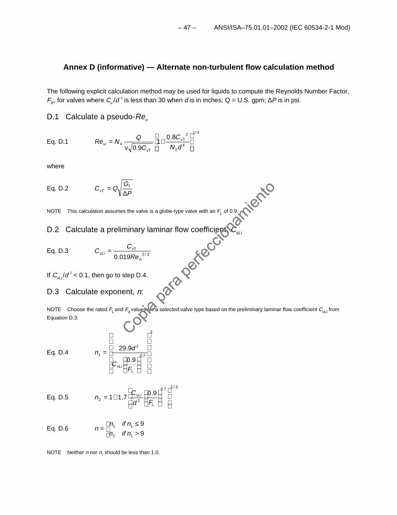
Annex D (informative) — Alternate non-turbulent flow calculation method
The following explicit calculation method may be used for liquids to compute the Reynolds Number Factor,FR, for valves where Cv /d 2 is less than 30 when d is in inches; Q = U.S. gpm; ∆P is in psi.
D.1 Calculate a pseudo-Revi
Eq. D.1
4/1
42
2vT
vT
4vi
8.01
9.0
+
ν=
dN
C
C
QNRe
where
Eq. D.2P
GQC
∆= f
vT
NOTE This calculation assumes the valve is a globe-type valve with an FL of 0.9.
D.2 Calculate a preliminary laminar flow coefficient, CvLi
Eq. D.33/2
vi
vTvLi
019.0 Re
CC =
If CvLi /d 2 < 0.1, then go to step D.4.
D.3 Calculate exponent, n:
NOTE Choose the rated FL and Fd values for a selected valve type based on the preliminary laminar flow coefficient CvLi from
Equation D.3.
Eq. D.4
2
7.0
LvLi
2
1
9.0
9.29
=
FC
dn
Eq. D.5
3/27.0
L2
vLi2
9.07.11
+=
Fd
Cn
Eq. D.6
>≤
=9
9
12
11
nifn
nifnn
NOTE Neither n nor n2 should be less than 1.0.
Copia
para
perfe
ccion
amien
to
Copia
para
perfe
ccion
amien
to
ANSI/ISA–75.01.01–2002 (IEC 60534-2-1 Mod) – 48 –
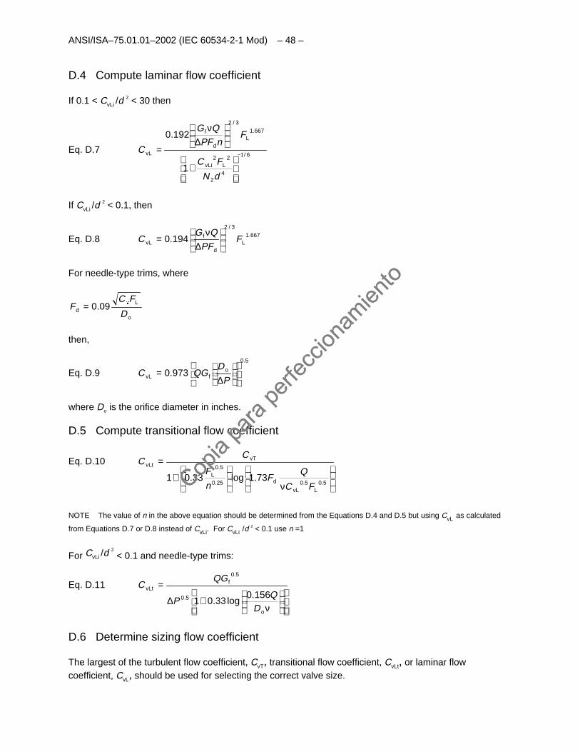
D.4 Compute laminar flow coefficient
If 0.1 < CvLi /d 2 < 30 then
Eq. D.76/1
42
2L
2vLi
667.1L
3/2
d
f
vL
1
192.0
−
+
∆
ν
=
dN
FC
FnPF
QG
C
If CvLi /d 2 < 0.1, then
Eq. D.8 667.1L
3/2
d
fvL 194.0 F
PFQG
C
∆
ν=
For needle-type trims, where
o
Ld 09.0
D
FCF =
then,
Eq. D.95.0
ofvL 973.0
∆
=P
DQGC
where Do is the orifice diameter in inches.
D.5 Compute transitional flow coefficient
Eq. D.10
ν
+
=
5.0L
5.0vL
d25.0
5.0L
vTvLt
73.1log33.01FC
QF
n
F
CC
NOTE The value of n in the above equation should be determined from the Equations D.4 and D.5 but using CvL as calculated
from Equations D.7 or D.8 instead of CvLi. For CvLi /d 2 < 0.1 use n =1
For CvLi /d 2 < 0.1 and needle-type trims:
Eq. D.11
ν
+∆
=
o
5.0
5.0f
vLt156.0
log33.01D
QP
QGC
D.6 Determine sizing flow coefficient
The largest of the turbulent flow coefficient, CvT, transitional flow coefficient, CvLt, or laminar flowcoefficient, CvL, should be used for selecting the correct valve size.
Copia
para
perfe
ccion
amien
to
Copia
para
perfe
ccion
amien
to
– 49 – ANSI/ISA–75.01.01–2002 (IEC 60534-2-1 Mod)
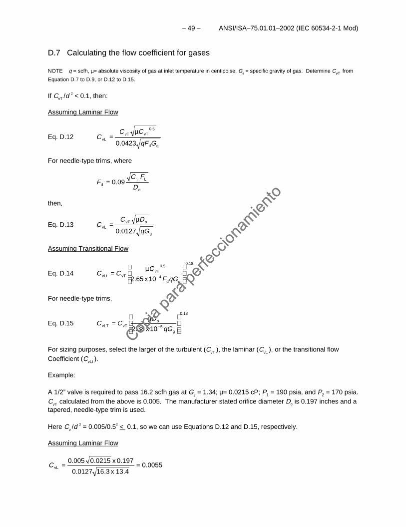
D.7 Calculating the flow coefficient for gases
NOTE q = scfh, µ= absolute viscosity of gas at inlet temperature in centipoise, Gg = specific gravity of gas. Determine CvT from
Equation D.7 to D.9, or D.12 to D.15.
If CvT /d 2 < 0.1, then:
Assuming Laminar Flow
Eq. D.12gd
5.0vTvT
vL0423.0 GqF
CCC
µ=
For needle-type trims, where
o
Ld 09.0
D
FCF =
then,
Eq. D.13g
ovTvL
0127.0 qG
DCC
µ=
Assuming Transitional Flow
Eq. D.14
18.0
gd4
5.0vT
vTvLt10x65.2
µ=
− qGF
CCC
For needle-type trims,
Eq. D.15
18.0
g5
ovTvLT
10x38.2
µ=
− qG
DCC
For sizing purposes, select the larger of the turbulent (CvT ), the laminar (CvL ), or the transitional flowCoefficient (CvLt ).
Example:
A 1/2” valve is required to pass 16.2 scfh gas at Gg = 1.34; µ= 0.0215 cP; P1 = 190 psia, and P2 = 170 psia.CvT calculated from the above is 0.005. The manufacturer stated orifice diameter Do is 0.197 inches and atapered, needle-type trim is used.
Here Cv /d 2 = 0.005/0.52 < 0.1, so we can use Equations D.12 and D.15, respectively.
Assuming Laminar Flow
0055.04.13x3.160127.0
197.0x0215.0005.0vL ==C
Copia
para
perfe
ccion
amien
to
Copia
para
perfe
ccion
amien
to
ANSI/ISA–75.01.01–2002 (IEC 60534-2-1 Mod) – 50 –
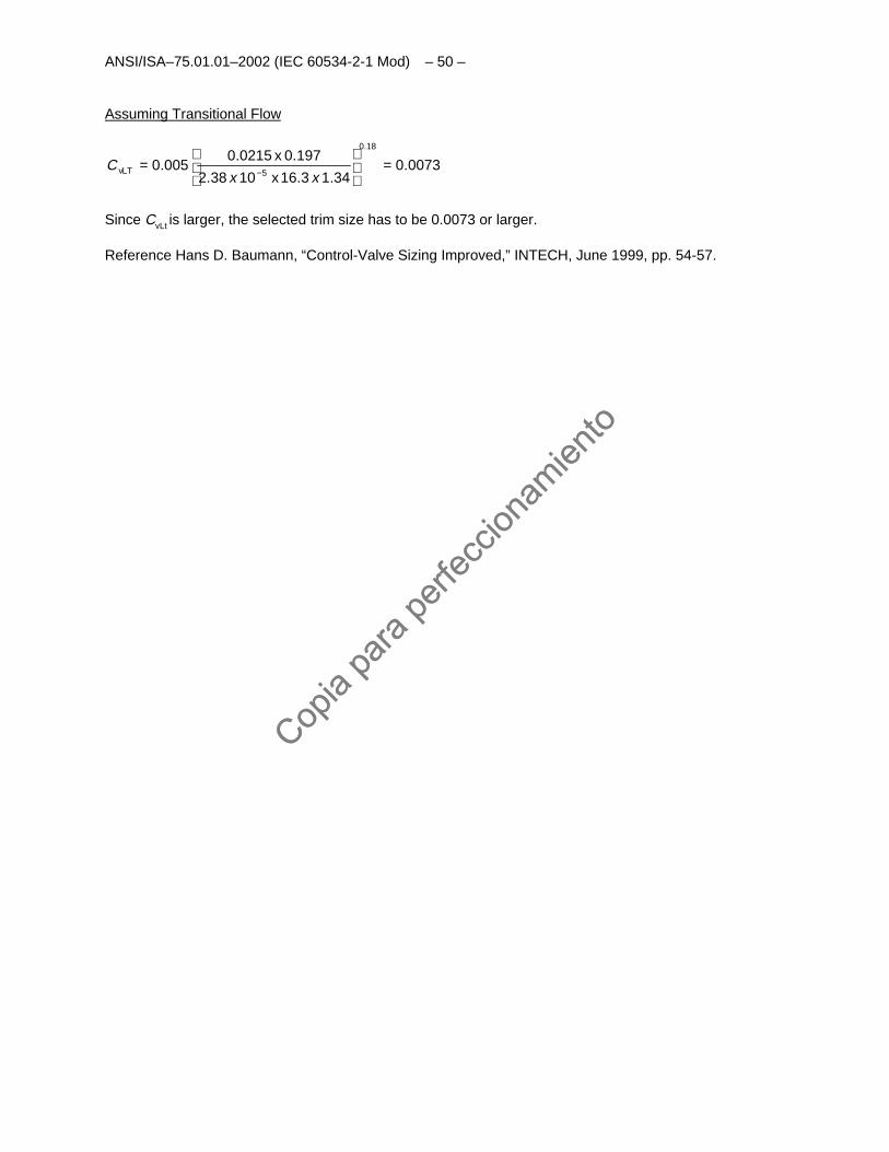
Assuming Transitional Flow
0073.034.13.16x1038.2
197.0x0215.0005.0
18.0
5LTv =
=
− xxC
Since CvLt is larger, the selected trim size has to be 0.0073 or larger.
Reference Hans D. Baumann, “Control-Valve Sizing Improved,” INTECH, June 1999, pp. 54-57.
Copia
para
perfe
ccion
amien
to
Copia
para
perfe
ccion
amien
to
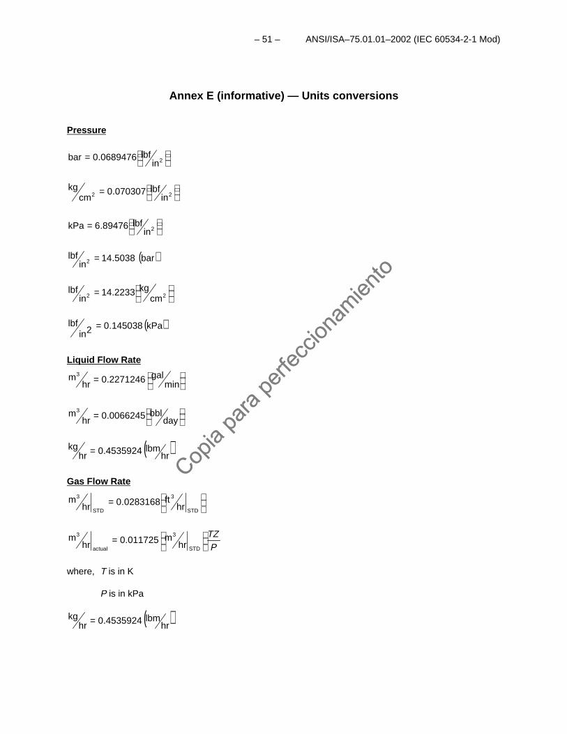
– 51 – ANSI/ISA–75.01.01–2002 (IEC 60534-2-1 Mod)
Annex E (informative) — Units conversions
Pressure
= 2inlbf0689476.0bar
= 22 inlbf070307.0
cmkg
= 2inlbf89476.6kPa
( )bar5038.14in
lbf2 =
= 22 cmkg2233.14
inlbf
( )kPa145038.02inlbf =
Liquid Flow Rate
= mingal2271246.0hr
m3
= daybbl0066245.0hr
m3
( )hrlbm4535924.0hr
kg =
Gas Flow Rate
=
STD
3
STD
3
hrft0283168.0hr
m
PTZ
=
STD
3
actual
3
hrm011725.0hr
m
where, T is in K
P is in kPa
( )hrlbm4535924.0hr
kg =
Copia
para
perfe
ccion
amien
to
Copia
para
perfe
ccion
amien
to
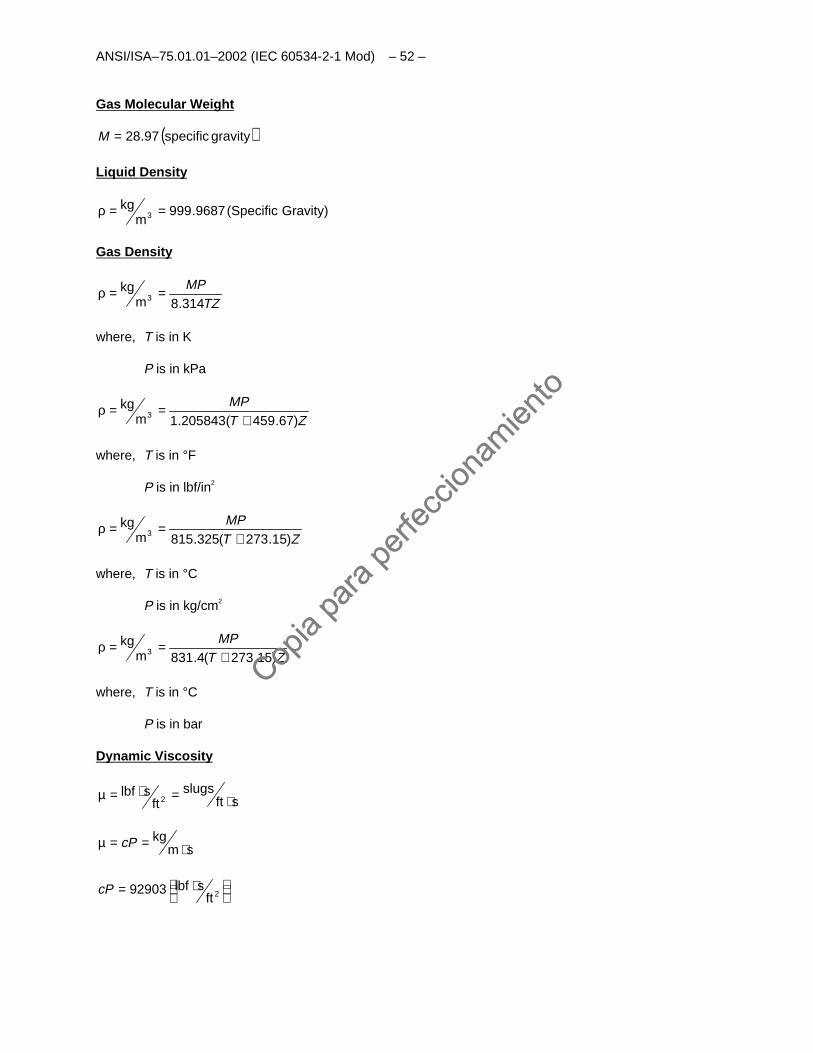
ANSI/ISA–75.01.01–2002 (IEC 60534-2-1 Mod) – 52 –
Gas Molecular Weight
( )gravityspecific97.28=M
Liquid Density
Gravity)(Specific9687.999m
kg3 ==ρ
Gas Density
TZMP314.8m
kg3 ==ρ
where, T is in K
P is in kPa
ZTMP
)67.459(205843.1mkg
3 +==ρ
where, T is in °F
P is in lbf/in2
ZTMP
)15.273(325.815mkg
3 +==ρ
where, T is in °C
P is in kg/cm2
ZTMP
)15.273(4.831mkg
3 +==ρ
where, T is in °C
P is in bar
Dynamic Viscosity
sftslugs
ftslbf
2 ⋅=⋅=µ
smkg
⋅==µ cP
⋅= 2ftslbf92903cP
Copia
para
perfe
ccion
amien
to
Copia
para
perfe
ccion
amien
to
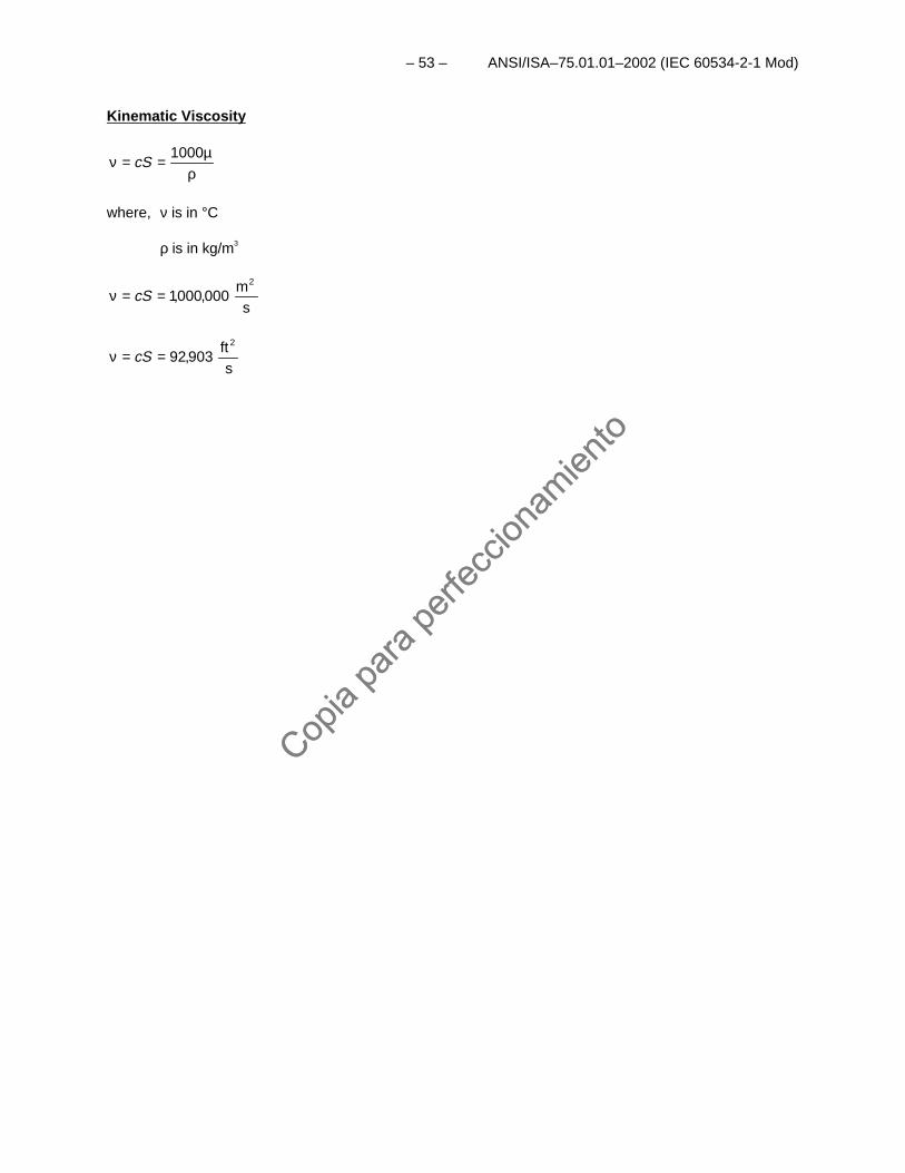
– 53 – ANSI/ISA–75.01.01–2002 (IEC 60534-2-1 Mod)
Kinematic Viscosity
ρµ==ν 1000
cS
where, ν is in °C
ρ is in kg/m3
sm
000,000,12
==ν cS
sft
903,922
==ν cS
Copia
para
perfe
ccion
amien
to
Copia
para
perfe
ccion
amien
to

This page intentionally left blank.
Copia
para
perfe
ccion
amien
to
Copia
para
perfe
ccion
amien
to
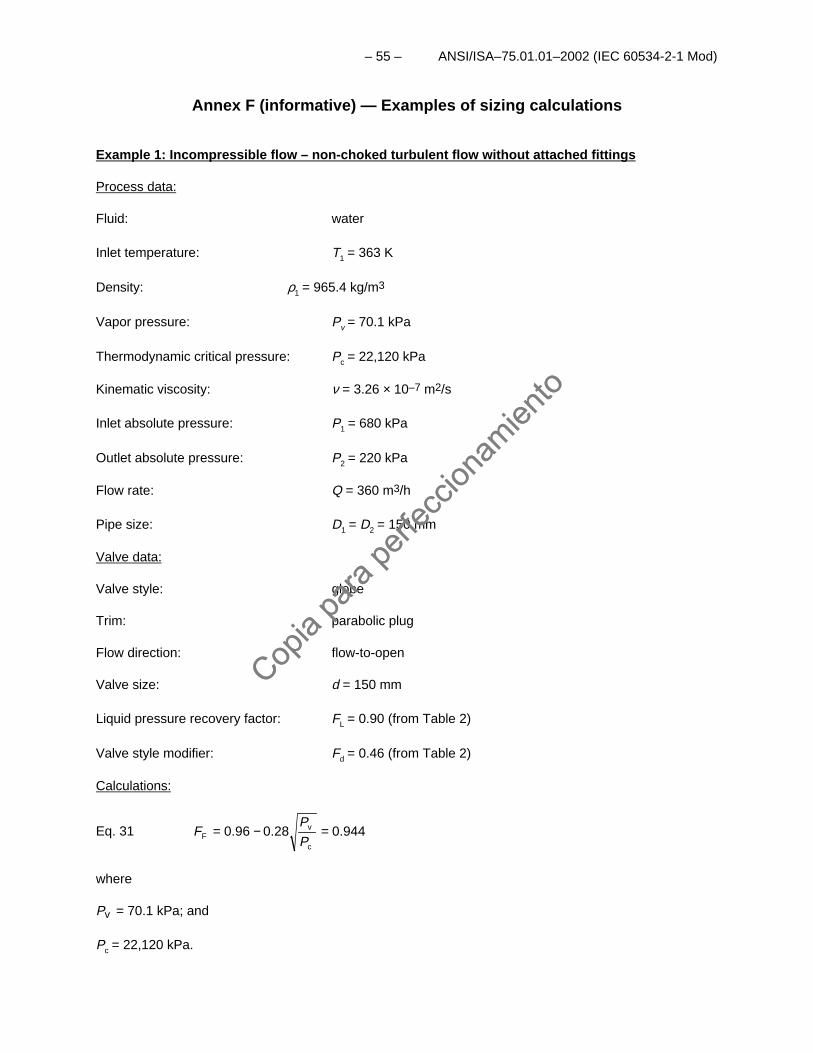
– 55 – ANSI/ISA–75.01.01–2002 (IEC 60534-2-1 Mod)
Annex F (informative) — Examples of sizing calculations
Example 1: Incompressible flow – non-choked turbulent flow without attached fittings
Process data:
Fluid: water
Inlet temperature: T1 = 363 K
Density: ρ1 = 965.4 kg/m3
Vapor pressure: Pv = 70.1 kPa
Thermodynamic critical pressure: Pc = 22,120 kPa
Kinematic viscosity: ν = 3.26 × 10⁻⁷ m2/s
Inlet absolute pressure: P1 = 680 kPa
Outlet absolute pressure: P2 = 220 kPa
Flow rate: Q = 360 m3/h
Pipe size: D1 = D2 = 150 mm
Valve data:
Valve style: globe
Trim: parabolic plug
Flow direction: flow-to-open
Valve size: d = 150 mm
Liquid pressure recovery factor: FL = 0.90 (from Table 2)
Valve style modifier: Fd = 0.46 (from Table 2)
Calculations:
Eq. 31 0.9440.28 0.96c
vF =−=
P
PF
where
Pv = 70.1 kPa; and
Pc = 22,120 kPa.
Copia
para
perfe
ccion
amien
to
Copia
para
perfe
ccion
amien
to
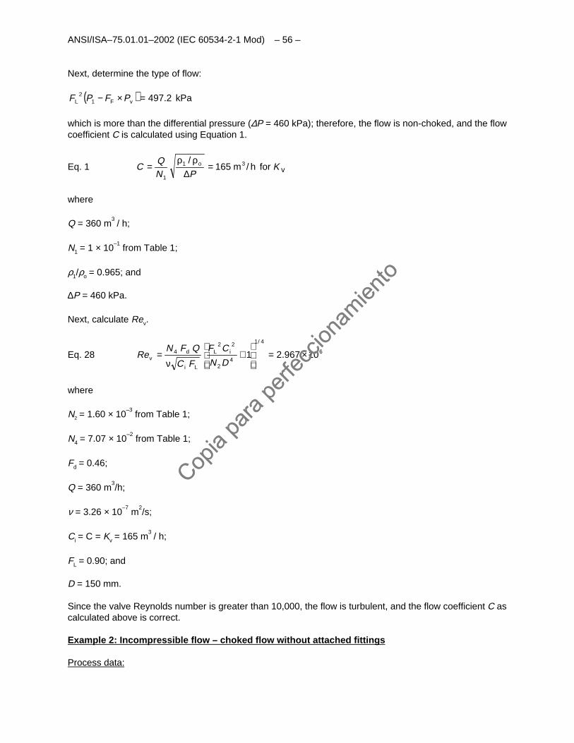
ANSI/ISA–75.01.01–2002 (IEC 60534-2-1 Mod) – 56 –
Next, determine the type of flow:
( ) kPa497.2vFL =×− PFPF 12
which is more than the differential pressure (∆P = 460 kPa); therefore, the flow is non-choked, and the flowcoefficient C is calculated using Equation 1.
Eq. 1 vfor h/mo KPN
QC 31
1
165/
=∆
ρρ=
where
Q = 360 m3 / h;
N1 = 1 × 10⁻¹
from Table 1;
ρ1/ρo = 0.965; and
∆P = 460 kPa.
Next, calculate Rev.
Eq. 28 6
4/1
42
224 10967.21
×=
+
ν=
DN
CF
FC
QFN iL
Li
dvRe
where
N2 = 1.60 × 10⁻³
from Table 1;
N4 = 7.07 × 10⁻²
from Table 1;
Fd = 0.46;
Q = 360 m3/h;
ν = 3.26 × 10⁻⁷
m2/s;
Ci = C = Kv = 165 m3 / h;
FL = 0.90; and
D = 150 mm.
Since the valve Reynolds number is greater than 10,000, the flow is turbulent, and the flow coefficient C ascalculated above is correct.
Example 2: Incompressible flow – choked flow without attached fittings
Process data:
Copia
para
perfe
ccion
amien
to
Copia
para
perfe
ccion
amien
to
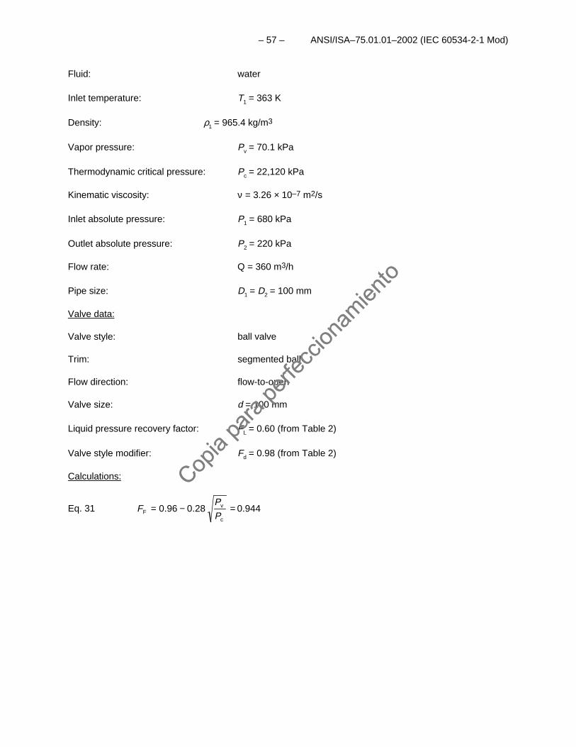
– 57 – ANSI/ISA–75.01.01–2002 (IEC 60534-2-1 Mod)
Fluid: water
Inlet temperature: T1 = 363 K
Density: ρ1 = 965.4 kg/m3
Vapor pressure: Pv = 70.1 kPa
Thermodynamic critical pressure: Pc = 22,120 kPa
Kinematic viscosity: ν = 3.26 × 10⁻⁷ m2/s
Inlet absolute pressure: P1 = 680 kPa
Outlet absolute pressure: P2 = 220 kPa
Flow rate: Q = 360 m3/h
Pipe size: D1 = D2 = 100 mm
Valve data:
Valve style: ball valve
Trim: segmented ball
Flow direction: flow-to-open
Valve size: d = 100 mm
Liquid pressure recovery factor: FL = 0.60 (from Table 2)
Valve style modifier: Fd = 0.98 (from Table 2)
Calculations:
Eq. 31 0.944 c
vF =−=
P
PF 28.096.0
Copia
para
perfe
ccion
amien
to
Copia
para
perfe
ccion
amien
to
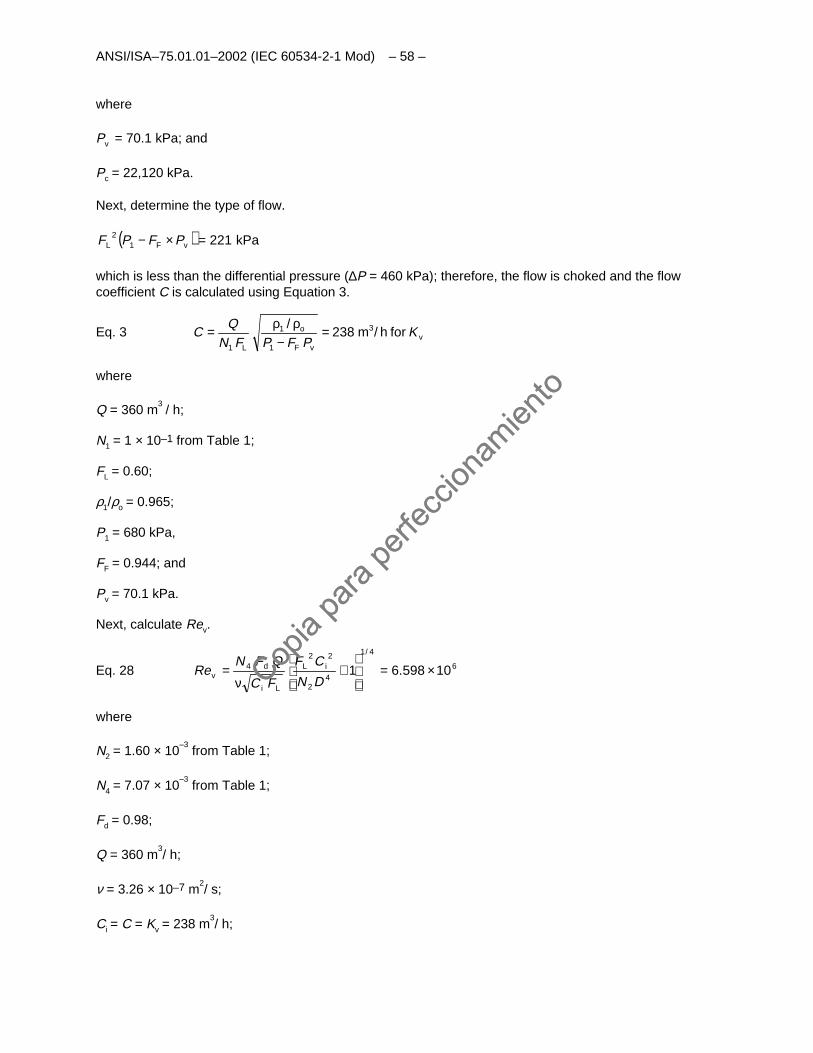
ANSI/ISA–75.01.01–2002 (IEC 60534-2-1 Mod) – 58 –
where
Pv = 70.1 kPa; and
Pc = 22,120 kPa.
Next, determine the type of flow.
( ) kPavFL 22112 =×− PFPF
which is less than the differential pressure (∆P = 460 kPa); therefore, the flow is choked and the flowcoefficient C is calculated using Equation 3.
Eq. 3 vvF
o
L
for h/m KPFPFN
QC 3
1
1
1
238
/
=−
ρρ=
where
Q = 360 m3 / h;
N1 = 1 × 10⁻¹ from Table 1;
FL = 0.60;
ρ1/ρo = 0.965;
P1 = 680 kPa,
FF = 0.944; and
Pv = 70.1 kPa.
Next, calculate Rev.
Eq. 28 6
4/1
42
224 10598.61
×=
+
ν=
DN
CF
FC
QFN iL
Li
dvRe
where
N2 = 1.60 × 10⁻³
from Table 1;
N4 = 7.07 × 10⁻³
from Table 1;
Fd = 0.98;
Q = 360 m3/ h;
ν = 3.26 × 10⁻⁷ m2/ s;
Ci = C = Kv = 238 m3/ h;
Copia
para
perfe
ccion
amien
to
Copia
para
perfe
ccion
amien
to
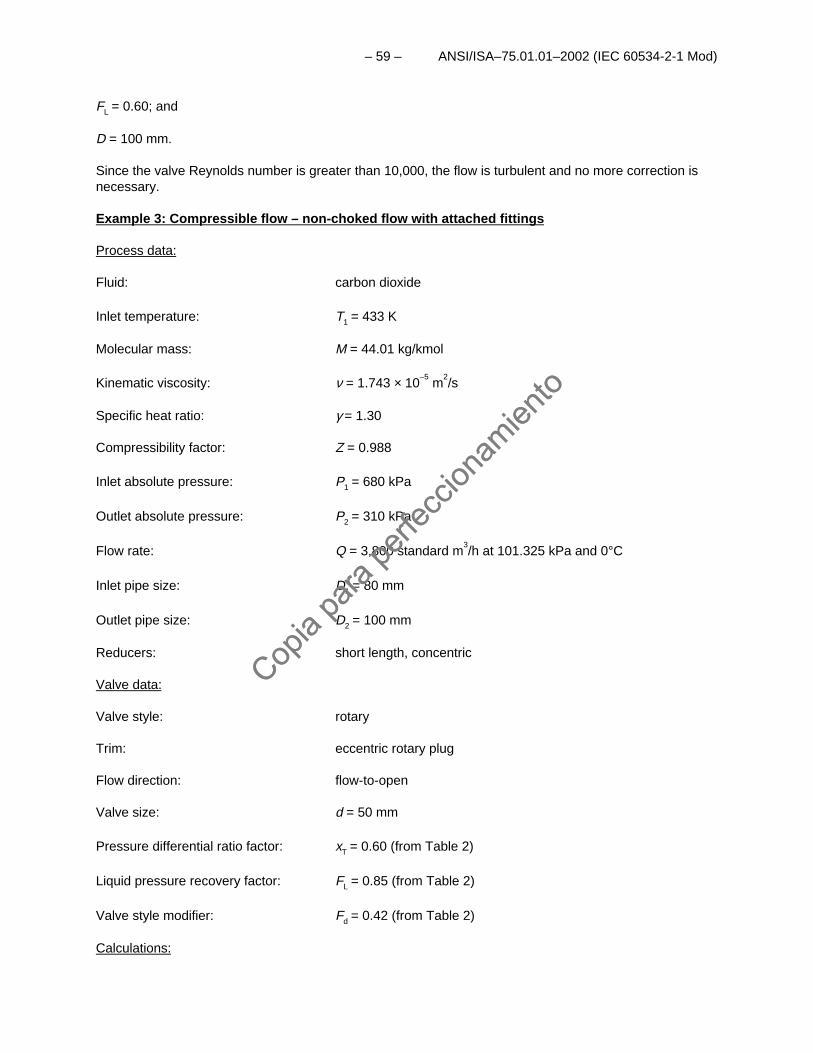
– 59 – ANSI/ISA–75.01.01–2002 (IEC 60534-2-1 Mod)
FL = 0.60; and
D = 100 mm.
Since the valve Reynolds number is greater than 10,000, the flow is turbulent and no more correction isnecessary.
Example 3: Compressible flow – non-choked flow with attached fittings
Process data:
Fluid: carbon dioxide
Inlet temperature: T1 = 433 K
Molecular mass: M = 44.01 kg/kmol
Kinematic viscosity: ν = 1.743 × 10⁻⁵
m2/s
Specific heat ratio: γ = 1.30
Compressibility factor: Z = 0.988
Inlet absolute pressure: P1 = 680 kPa
Outlet absolute pressure: P2 = 310 kPa
Flow rate: Q = 3,800 standard m3/h at 101.325 kPa and 0°C
Inlet pipe size: D1 = 80 mm
Outlet pipe size: D2 = 100 mm
Reducers: short length, concentric
Valve data:
Valve style: rotary
Trim: eccentric rotary plug
Flow direction: flow-to-open
Valve size: d = 50 mm
Pressure differential ratio factor: xT = 0.60 (from Table 2)
Liquid pressure recovery factor: FL = 0.85 (from Table 2)
Valve style modifier: Fd = 0.42 (from Table 2)
Calculations:
Copia
para
perfe
ccion
amien
to
Copia
para
perfe
ccion
amien
to
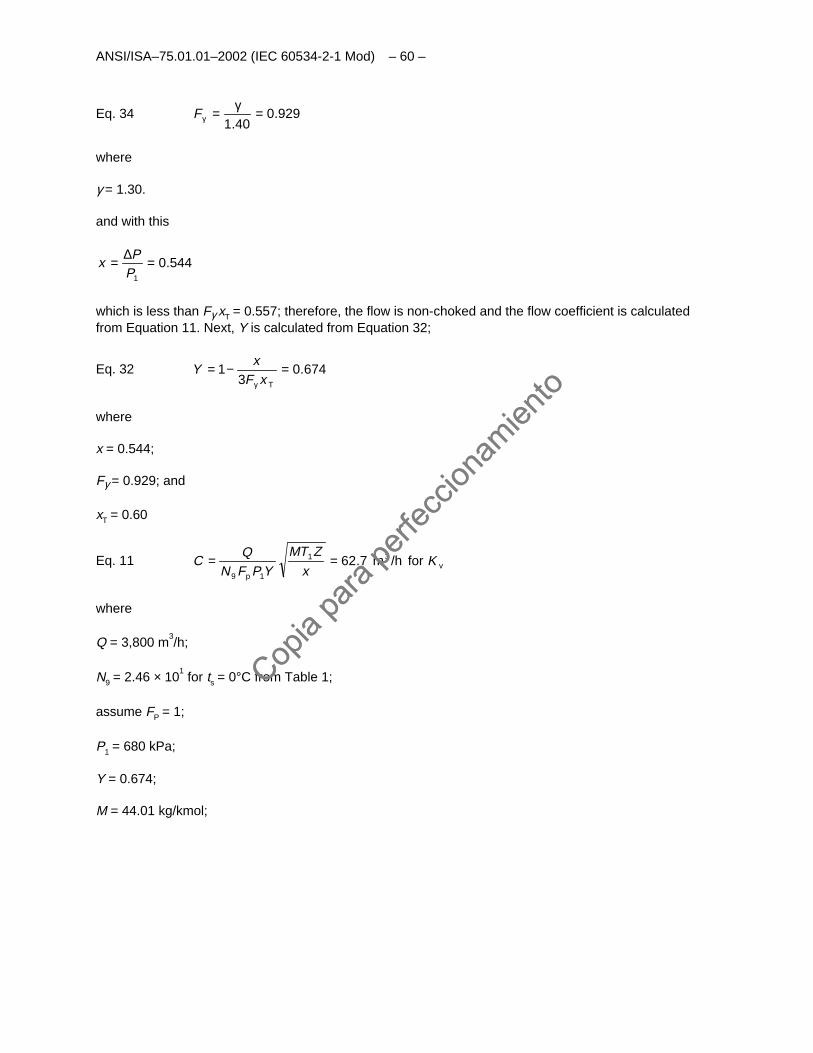
ANSI/ISA–75.01.01–2002 (IEC 60534-2-1 Mod) – 60 –
Eq. 34 929.040.1
=γ=γF
where
γ = 1.30.
and with this
544.01
=∆=PP
x
which is less than Fγ xT = 0.557; therefore, the flow is non-choked and the flow coefficient is calculatedfrom Equation 11. Next, Y is calculated from Equation 32;
Eq. 32 674.03
1 =−=γ TxFx
Y
where
x = 0.544;
Fγ = 0.929; and
xT = 0.60
Eq. 11 vp
for /hm Kx
ZTM
YPFNQ
C 31
19
7.62==
where
Q = 3,800 m3/h;
N9 = 2.46 × 101 for ts = 0°C from Table 1;
assume FP = 1;
P1 = 680 kPa;
Y = 0.674;
M = 44.01 kg/kmol;
Copia
para
perfe
ccion
amien
to
Copia
para
perfe
ccion
amien
to
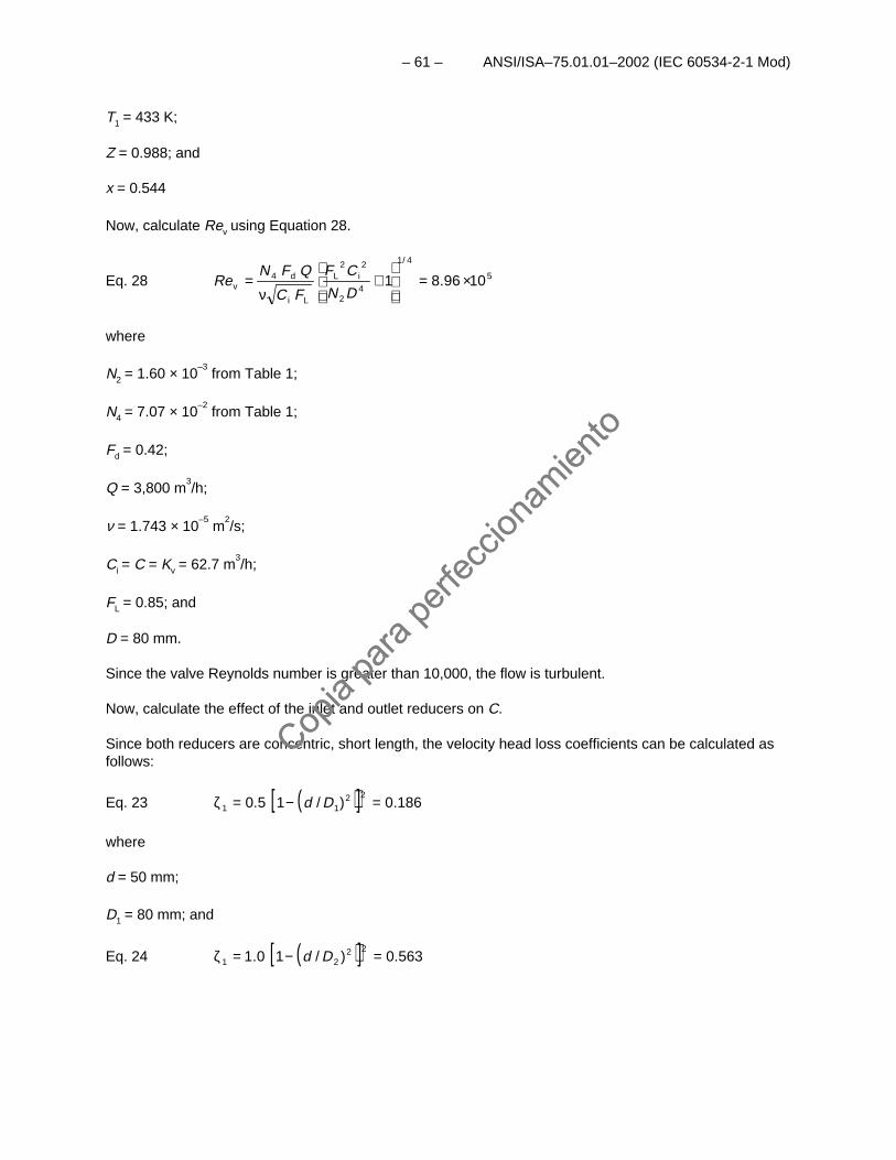
– 61 – ANSI/ISA–75.01.01–2002 (IEC 60534-2-1 Mod)
T1 = 433 K;
Z = 0.988; and
x = 0.544
Now, calculate Rev using Equation 28.
Eq. 28 5
4/1
42
224 1096.81
×=
+
ν=
DN
CF
FC
QFN iL
Li
dvRe
where
N2 = 1.60 × 10⁻³
from Table 1;
N4 = 7.07 × 10⁻²
from Table 1;
Fd = 0.42;
Q = 3,800 m3/h;
ν = 1.743 × 10⁻⁵
m2/s;
Ci = C = Kv = 62.7 m3/h;
FL = 0.85; and
D = 80 mm.
Since the valve Reynolds number is greater than 10,000, the flow is turbulent.
Now, calculate the effect of the inlet and outlet reducers on C.
Since both reducers are concentric, short length, the velocity head loss coefficients can be calculated asfollows:
Eq. 23 ( )[ ] 186.0)/15.022
11 =−=ζ Dd
where
d = 50 mm;
D1 = 80 mm; and
Eq. 24 ( )[ ] 563.0)/10.122
21 =−=ζ Dd
Copia
para
perfe
ccion
amien
to
Copia
para
perfe
ccion
amien
to
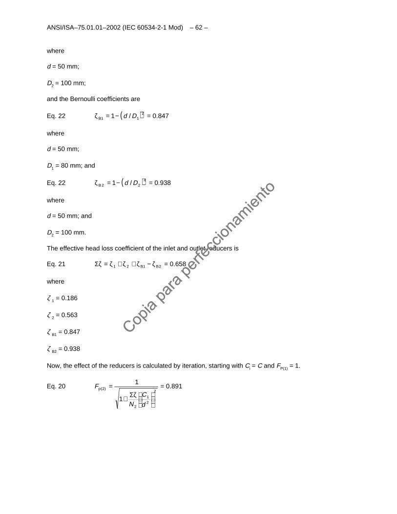
ANSI/ISA–75.01.01–2002 (IEC 60534-2-1 Mod) – 62 –
where
d = 50 mm;
D2 = 100 mm;
and the Bernoulli coefficients are
Eq. 22 ( ) 847.0/1 21 =−=ζ DdB1
where
d = 50 mm;
D1 = 80 mm; and
Eq. 22 ( ) 938.0/1 422B =−=ζ Dd
where
d = 50 mm; and
D2 = 100 mm.
The effective head loss coefficient of the inlet and outlet reducers is
Eq. 21 658.02121 =ζ−ζ+ζ+ζ=ζΣ BB
where
ζ 1 = 0.186
ζ 2 = 0.563
ζ B1 = 0.847
ζ B2 = 0.938
Now, the effect of the reducers is calculated by iteration, starting with Ci = C and FP(1) = 1.
Eq. 20 891.0
1
12
21
2
)2( =
ζΣ+
=
d
CN
Fp
Copia
para
perfe
ccion
amien
to
Copia
para
perfe
ccion
amien
to
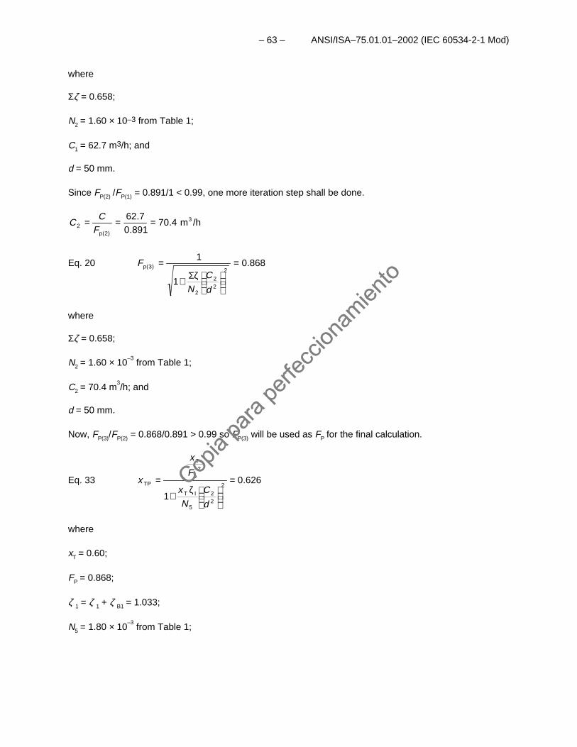
– 63 – ANSI/ISA–75.01.01–2002 (IEC 60534-2-1 Mod)
where
Σζ = 0.658;
N2 = 1.60 × 10⁻³ from Table 1;
C1 = 62.7 m3/h; and
d = 50 mm.
Since FP(2) /FP(1) = 0.891/1 < 0.99, one more iteration step shall be done.
/hm4.70891.0
7.62 3
)2(2 ===
pFC
C
Eq. 20 868.0
1
12
22
2
)3( =
ζΣ+
=
d
CN
Fp
where
Σζ = 0.658;
N2 = 1.60 × 10⁻³
from Table 1;
C2 = 70.4 m3/h; and
d = 50 mm.
Now, FP(3)/FP(2) = 0.868/0.891 > 0.99 so FP(3) will be used as FP for the final calculation.
Eq. 33 626.0
12
22
5
2
=
ζ
+
=
d
CN
x
F
x
xIT
p
T
TP
where
xT = 0.60;
FP = 0.868;
ζ 1 = ζ 1 + ζ B1 = 1.033;
N5 = 1.80 × 10⁻³
from Table 1;
Copia
para
perfe
ccion
amien
to
Copia
para
perfe
ccion
amien
to
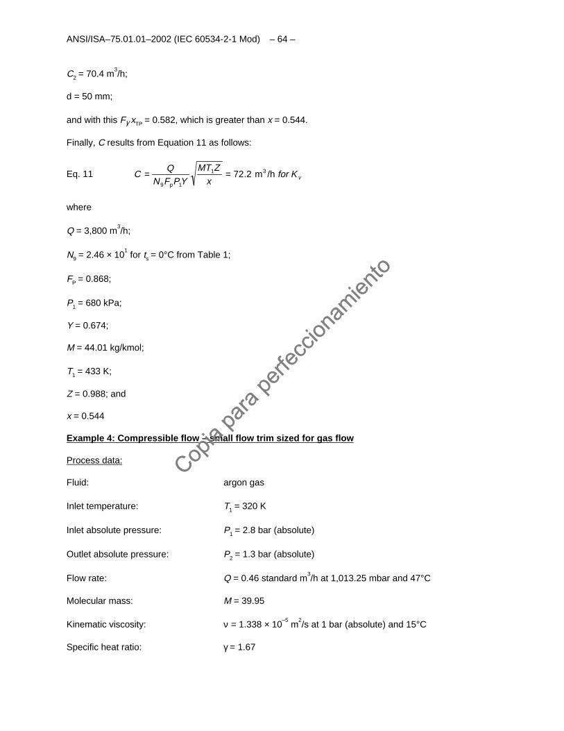
ANSI/ISA–75.01.01–2002 (IEC 60534-2-1 Mod) – 64 –
C2 = 70.4 m3/h;
d = 50 mm;
and with this Fγ xTP = 0.582, which is greater than x = 0.544.
Finally, C results from Equation 11 as follows:
Eq. 11 vKforx
ZMT
YPFNQ
C /hm2.72 31
1p9
==
where
Q = 3,800 m3/h;
N9 = 2.46 × 101 for ts = 0°C from Table 1;
FP = 0.868;
P1 = 680 kPa;
Y = 0.674;
M = 44.01 kg/kmol;
T1 = 433 K;
Z = 0.988; and
x = 0.544
Example 4: Compressible flow – small flow trim sized for gas flow
Process data:
Fluid: argon gas
Inlet temperature: T1 = 320 K
Inlet absolute pressure: P1 = 2.8 bar (absolute)
Outlet absolute pressure: P2 = 1.3 bar (absolute)
Flow rate: Q = 0.46 standard m3/h at 1,013.25 mbar and 47°C
Molecular mass: M = 39.95
Kinematic viscosity: ν = 1.338 × 10⁻⁵
m2/s at 1 bar (absolute) and 15°C
Specific heat ratio: γ = 1.67
Copia
para
perfe
ccion
amien
to
Copia
para
perfe
ccion
amien
to
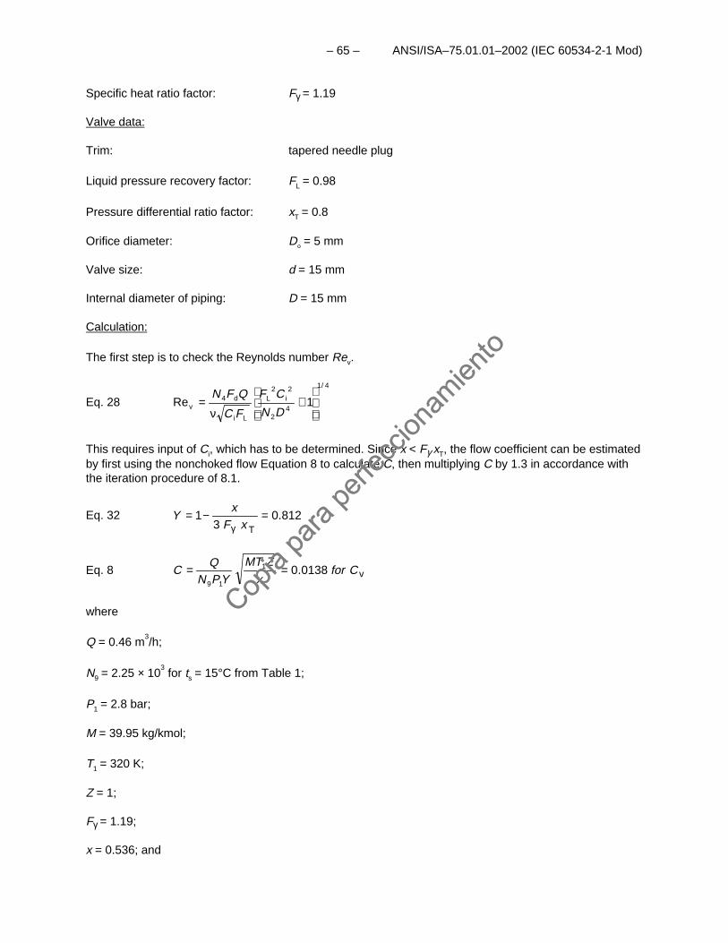
– 65 – ANSI/ISA–75.01.01–2002 (IEC 60534-2-1 Mod)
Specific heat ratio factor: Fγ = 1.19
Valve data:
Trim: tapered needle plug
Liquid pressure recovery factor: FL = 0.98
Pressure differential ratio factor: xT = 0.8
Orifice diameter: Do = 5 mm
Valve size: d = 15 mm
Internal diameter of piping: D = 15 mm
Calculation:
The first step is to check the Reynolds number Rev.
Eq. 28
4/1
42
2i
2L
Li
d4v 1Re
+
ν=
DN
CF
FC
QFN
This requires input of Ci, which has to be determined. Since x < Fγ xT, the flow coefficient can be estimatedby first using the nonchoked flow Equation 8 to calculate C, then multiplying C by 1.3 in accordance withthe iteration procedure of 8.1.
Eq. 32 812.03
1T
=−=γ xFx
Y
Eq. 8 v0138.01
19
Cforx
ZMTYPN
QC ==
where
Q = 0.46 m3/h;
N9 = 2.25 × 10³ for ts = 15°C from Table 1;
P1 = 2.8 bar;
M = 39.95 kg/kmol;
T1 = 320 K;
Z = 1;
Fγ = 1.19;
x = 0.536; and
Copia
para
perfe
ccion
amien
to
Copia
para
perfe
ccion
amien
to
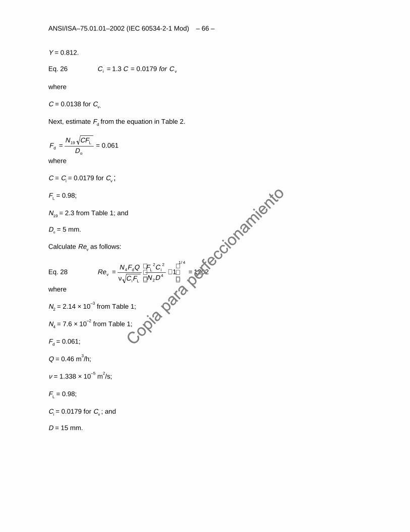
ANSI/ISA–75.01.01–2002 (IEC 60534-2-1 Mod) – 66 –
Y = 0.812.
Eq. 26 vi 0179.03.1 CforCC ==
where
C = 0.0138 for Cv.
Next, estimate Fd from the equation in Table 2.
061.0o
L19d ==
D
CFNF
where
C = Ci = 0.0179 for Cv ;
FL = 0.98;
N19 = 2.3 from Table 1; and
Do = 5 mm.
Calculate Rev as follows:
Eq. 28 202,11
4/1
42
2i
2L
Li
d4v =
+
ν=
DN
CF
FC
QFNRe
where
N2 = 2.14 × 10⁻³
from Table 1;
N4 = 7.6 × 10⁻²
from Table 1;
Fd = 0.061;
Q = 0.46 m3/h;
ν = 1.338 × 10⁻⁵
m2/s;
FL = 0.98;
Ci = 0.0179 for Cv ; and
D = 15 mm.
Copia
para
perfe
ccion
amien
to
Copia
para
perfe
ccion
amien
to
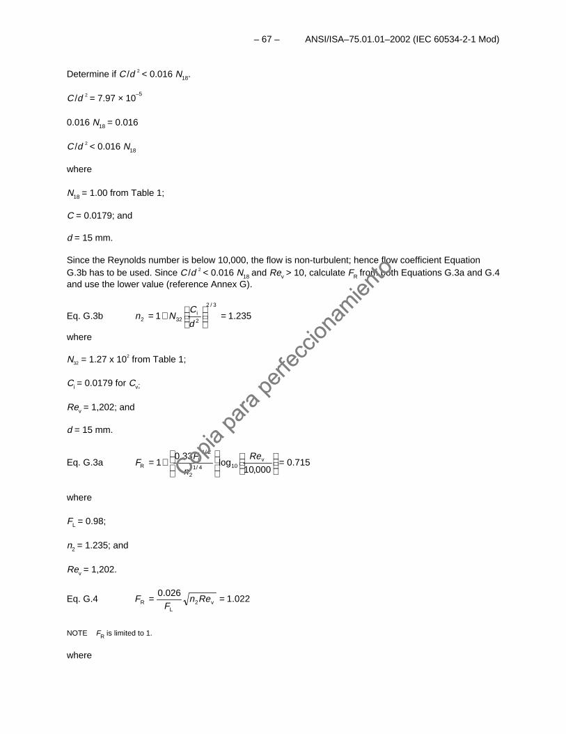
– 67 – ANSI/ISA–75.01.01–2002 (IEC 60534-2-1 Mod)
Determine if C /d 2 < 0.016 N18.
C /d 2 = 7.97 × 10⁻⁵
0.016 N18 = 0.016
C /d 2 < 0.016 N18
where
N18 = 1.00 from Table 1;
C = 0.0179; and
d = 15 mm.
Since the Reynolds number is below 10,000, the flow is non-turbulent; hence flow coefficient EquationG.3b has to be used. Since C /d 2 < 0.016 N18 and Rev > 10, calculate FR from both Equations G.3a and G.4and use the lower value (reference Annex G).
Eq. G.3b 235.113/2
=
+=2i
322d
CNn
where
N32 = 1.27 x 10² from Table 1;
Ci = 0.0179 for Cv;
Rev = 1,202; and
d = 15 mm.
Eq. G.3a 715.0000,10
log33.0
1 104/1
2/1
=
+= v
2
LR
Re
n
FF
where
FL = 0.98;
n2 = 1.235; and
Rev = 1,202.
Eq. G.4 022.1026.0
v2L
R == RenF
F
NOTE FR is limited to 1.
where
Copia
para
perfe
ccion
amien
to
Copia
para
perfe
ccion
amien
to
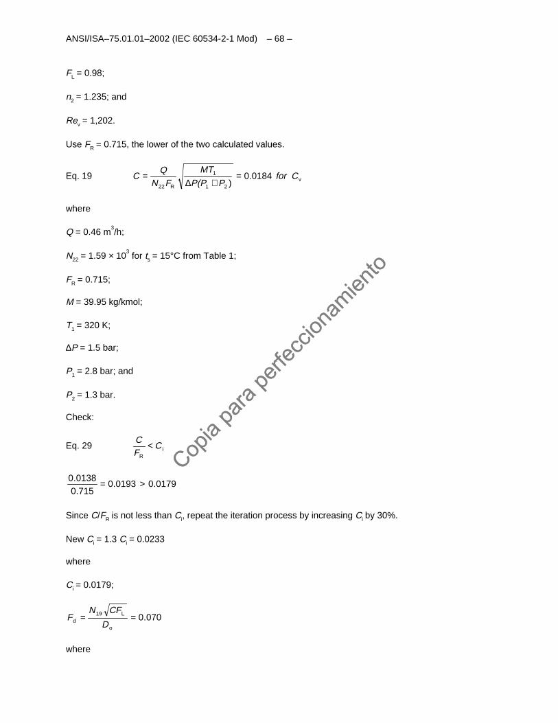
ANSI/ISA–75.01.01–2002 (IEC 60534-2-1 Mod) – 68 –
FL = 0.98;
n2 = 1.235; and
Rev = 1,202.
Use FR = 0.715, the lower of the two calculated values.
Eq. 19 v21
1
R22
0184.0)
CPP(P
MT
FNQ
C for=+∆
=
where
Q = 0.46 m3/h;
N22 = 1.59 × 10³ for ts = 15°C from Table 1;
FR = 0.715;
M = 39.95 kg/kmol;
T1 = 320 K;
∆P = 1.5 bar;
P1 = 2.8 bar; and
P2 = 1.3 bar.
Check:
Eq. 29 iR
CFC <
0179.00193.0715.00138.0 >=
Since C/FR is not less than Ci, repeat the iteration process by increasing Ci by 30%.
New Ci = 1.3 Ci = 0.0233
where
Ci = 0.0179;
070.0o
L19d ==
D
CFNF
where
Copia
para
perfe
ccion
amien
to
Copia
para
perfe
ccion
amien
to
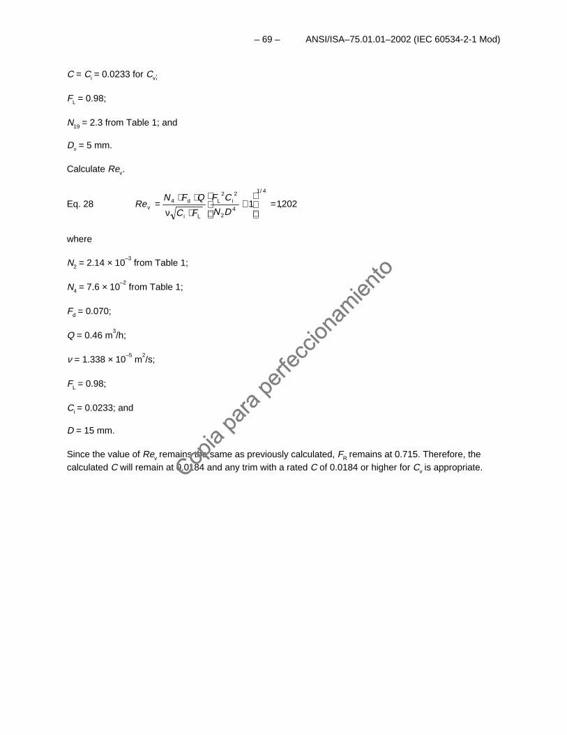
– 69 – ANSI/ISA–75.01.01–2002 (IEC 60534-2-1 Mod)
C = Ci = 0.0233 for Cv;
FL = 0.98;
N19 = 2.3 from Table 1; and
Do = 5 mm.
Calculate Rev.
Eq. 28 202,11
4/1
42
2i
2L
Li
d4v =
+
⋅ν
⋅⋅=
DN
CF
FC
QFNRe
where
N2 = 2.14 × 10⁻³
from Table 1;
N4 = 7.6 × 10⁻²
from Table 1;
Fd = 0.070;
Q = 0.46 m3/h;
ν = 1.338 × 10⁻⁵
m2/s;
FL = 0.98;
Ci = 0.0233; and
D = 15 mm.
Since the value of Rev remains the same as previously calculated, FR remains at 0.715. Therefore, thecalculated C will remain at 0.0184 and any trim with a rated C of 0.0184 or higher for Cv is appropriate.Cop
ia pa
ra pe
rfecc
ionam
iento
Copia
para
perfe
ccion
amien
to

This page intentionally left blank.
Copia
para
perfe
ccion
amien
to
Copia
para
perfe
ccion
amien
to
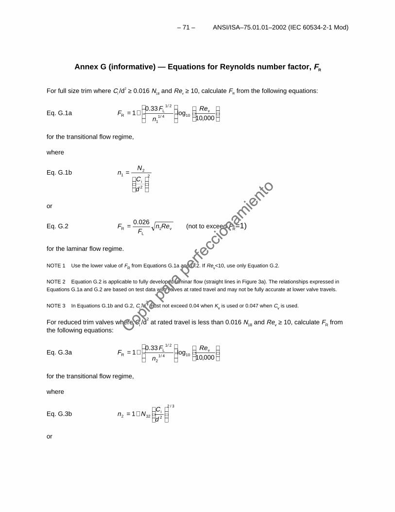
– 71 – ANSI/ISA–75.01.01–2002 (IEC 60534-2-1 Mod)
Annex G (informative) — Equations for Reynolds number factor, FR
For full size trim where Ci /d2 ≥ 0.016 N18 and Rev ≥ 10, calculate FR from the following equations:
Eq. G.1a
+=
000,10log
33.01 v
104/11
2/1L
R
Re
n
FF
for the transitional flow regime,
where
Eq. G.1b2
2i
21
=
d
C
Nn
or
Eq. G.2 v1L
R
026.0Ren
FF = (not to exceed FR=1)
for the laminar flow regime.
NOTE 1 Use the lower value of FR from Equations G.1a and G.2. If Rev<10, use only Equation G.2.
NOTE 2 Equation G.2 is applicable to fully developed laminar flow (straight lines in Figure 3a). The relationships expressed in
Equations G.1a and G.2 are based on test data with valves at rated travel and may not be fully accurate at lower valve travels.
NOTE 3 In Equations G.1b and G.2, Ci /d2 must not exceed 0.04 when Kv is used or 0.047 when Cv is used.
For reduced trim valves where Ci /d2 at rated travel is less than 0.016 N18 and Rev ≥ 10, calculate FR from
the following equations:
Eq. G.3a
+=
000,10log
33.01 v
104/12
2/1L
R
Re
n
FF
for the transitional flow regime,
where
Eq. G.3b3/2
2i
322 1
+=d
CNn
or
Copia
para
perfe
ccion
amien
to
Copia
para
perfe
ccion
amien
to
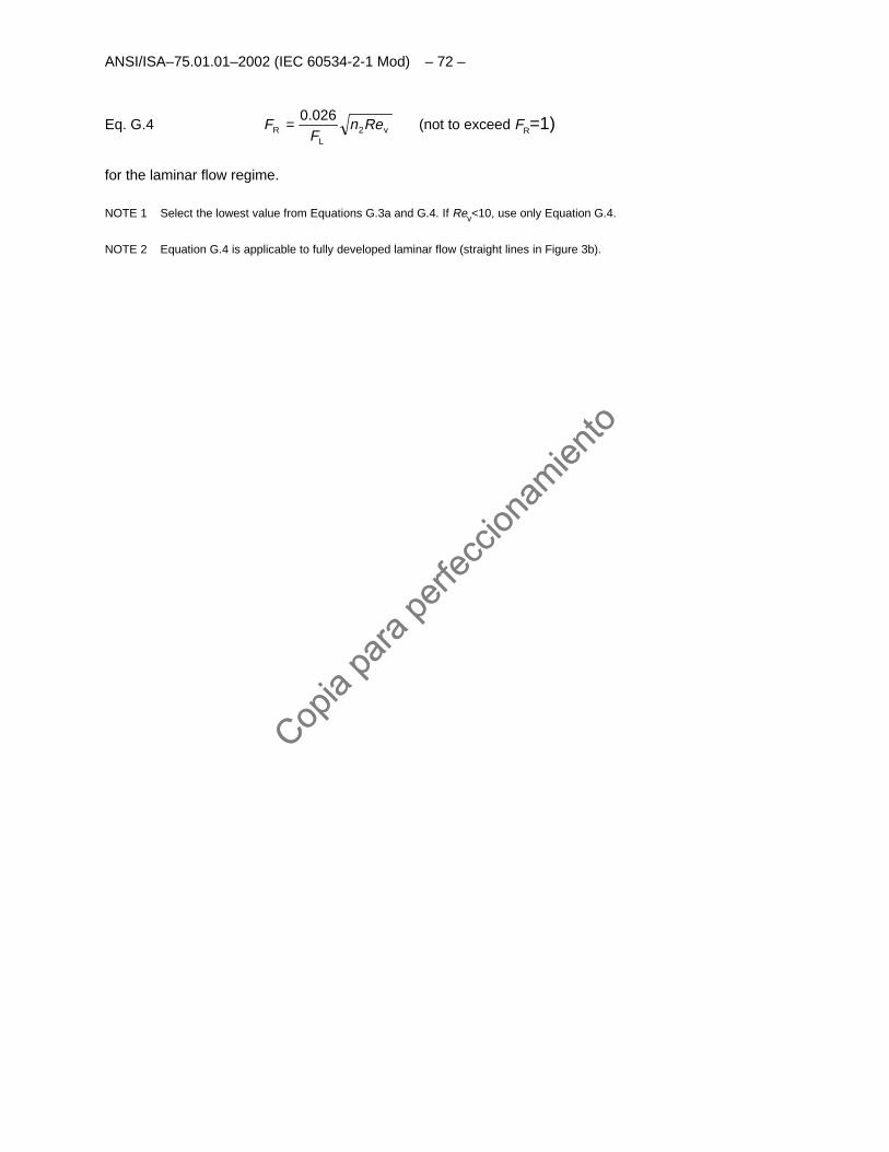
ANSI/ISA–75.01.01–2002 (IEC 60534-2-1 Mod) – 72 –
Eq. G.4 v2L
R
026.0Ren
FF = (not to exceed FR=1)
for the laminar flow regime.
NOTE 1 Select the lowest value from Equations G.3a and G.4. If Rev<10, use only Equation G.4.
NOTE 2 Equation G.4 is applicable to fully developed laminar flow (straight lines in Figure 3b).
Copia
para
perfe
ccion
amien
to
Copia
para
perfe
ccion
amien
to
– 73 – ANSI/ISA–75.01.01–2002 (IEC 60534-2-1 Mod)
Annex H (informative) — Bibliography
INTERNATIONAL ELECTROTECHNICAL COMMISSION (IEC)
IEC 60534-1 Part 1: Control Valve Terminology and General Considerations, 1987
IEC 60534-2-1 Part 2-1: Flow Capacity; Sizing Equations for Fluid Flow Under InstalledConditions, 1998
IEC 60534-2-3 Part 2-3: Flow Capacity - Test Procedures, 1997
Available from: ANSI25 West 43rd StreetFourth FloorNew York, NY 10036
ISA
ANSI/ISA-75.02-1996 Control Valve Capacity Test Procedures
ANSI/ISA-75.05.01-2000 Control Valve Terminology
Baumann, H.D., "Effect of Pipe Reducers on Control Valve Capacity," Instruments and Control Systems,December 1968.
Baumann, H.D., "The Introduction of a Critical Flow Factor for Valve Sizing," ISA Transactions, Vol. 2.,1963.
Buresh, J.F. and C. B. Schuder, "The Development of a Universal Gas Sizing Equation for ControlValves," ISA Transactions, Vol. 3, 1964.
Driskell, L.R., Control Valve Selection and Sizing, 1983.
George, J.A., Evolution and Status of Nonturbulent Flow Sizing for Control Valves, 2001.
ISA Handbook of Control Valves, 2nd ed., 1976.
McCutcheon, E.B., "A Reynolds Number for Control Valves," Symposium on Flow, Its Measurement andControl in Science and Industry, Vol. 1, Part 3, 1974.
Available from: ISA67 Alexander DrivePO Box 12277Research Triangle Park, NC 27709Tel: (919) 990-9200
Copia
para
perfe
ccion
amien
to
Copia
para
perfe
ccion
amien
to
ANSI/ISA–75.01.01–2002 (IEC 60534-2-1 Mod) – 74 –
MISCELLANEOUS
Allen, W.F., Jr., "Flow of a Flashing Mixture of Water and Steam Through Pipes and Valves," Journal ofBasic Engineering, April 1951.
Bailey, J.F., "Metastable Flow of Saturated Water," Journal of Basic Engineering, November 1951
Baumann, H.D., "A Unifying Method for Sizing Throttling Valves Under Laminar or Transitional FlowConditions," Journal of Fluids Engineering, Vol. 115, No. 1, March 1993, pp. 166-168.
Burnell, J.G., "Flow of Boiling Water through Nozzles, Orifices and Pipes," Engineering, December 12,1947.
Singleton, E.W., Multistage Valve Sizing Made Easy," INTECH, August 1997, pp. 47-51.
Stiles, G.F., "Liquid Viscosity Effects on Control Valve Sizing," Technical Manual TM 17A, October 1967,Fisher Governor Company, Marshalltown, Iowa.
Copia
para
perfe
ccion
amien
to
Copia
para
perfe
ccion
amien
to

This page intentionally left blank.
Copia
para
perfe
ccion
amien
to
Copia
para
perfe
ccion
amien
to
Developing and promulgating sound consensus standards, recommended practices, and technical reportsis one of ISA’s primary goals. To achieve this goal the Standards and Practices Department relies on thetechnical expertise and efforts of volunteer committee members, chairmen and reviewers.
ISA is an American National Standards Institute (ANSI) accredited organization. ISA administers UnitedStates Technical Advisory Groups (USTAGs) and provides secretariat support for InternationalElectrotechnical Commission (IEC) and International Organization for Standardization (ISO) committeesthat develop process measurement and control standards. To obtain additional information on theSociety’s standards program, please write:
ISAAttn: Standards Department67 Alexander DriveP.O. Box 12277Research Triangle Park, NC 27709
ISBN: 1-55617-780-1
Copia
para
perfe
ccion
amien
to
Copia
para
perfe
ccion
amien
to