Embed Size (px)
Citation preview
RESEARCH ARTICLE
Flow control for aero-optics application
B. Vukasinovic • A. Glezer • S. Gordeyev •
E. Jumper • W. W. Bower
Received: 20 April 2012 / Revised: 11 February 2013 / Accepted: 22 February 2013 / Published online: 15 March 2013
� Springer-Verlag Berlin Heidelberg 2013
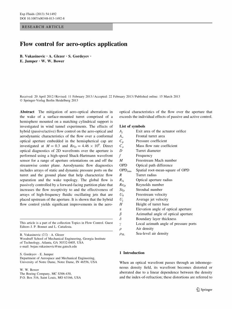
Abstract The mitigation of aero-optical aberrations in
the wake of a surface-mounted turret comprised of a
hemisphere mounted on a matching cylindrical support is
investigated in wind tunnel experiments. The effects of
hybrid (passive/active) flow control on the aero-optical and
aerodynamic characteristics of the flow over a conformal
optical aperture embedded in the hemispherical cap are
investigated at M = 0.3 and ReD = 4.46 9 106. Direct
optical diagnostics of 2D wavefronts over the aperture is
performed using a high-speed Shack-Hartmann wavefront
sensor for a range of aperture orientations on and off the
streamwise center plane. Aerodynamic flow diagnostics
includes arrays of static and dynamic pressure ports on the
turret and the ground plane that help characterize flow
separation and the wake topology. The global flow is
passively controlled by a forward-facing partition plate that
increases the flow receptivity to and the effectiveness of
arrays of high-frequency fluidic oscillating jets that are
placed upstream of the aperture. It is shown that the hybrid
flow control yields significant improvements in the aero-
optical characteristics of the flow over the aperture that
exceeds the individual effects of passive and active control.
List of symbols
Aj Exit area of the actuator orifice
Ao Frontal turret area
Cp Pressure coefficient
Cl Mass flow rate coefficient
D Turret diameter
f Frequency
M Freestream Mach number
OPD Optical path difference
OPDrms Spatial root-mean-square of OPD
R Turret radius
RA Optical aperture radius
ReD Reynolds number
StD Strouhal number
U0 Freestream velocity
Uj Average jet velocity
H Height of turret base
a Elevation angle of optical aperture
b Azimuthal angle of optical aperture
d Boundary layer thickness
c Local azimuth angle of pressure ports
q Air density
qSL Sea-level air density
1 Introduction
When an optical wavefront passes through an inhomoge-
neous density field, its wavefront becomes distorted or
aberrated due to a linear dependence between the density
and the index-of-refraction; these distortions are referred to
This article is a part of the collection Topics in Flow Control. Guest
Editors J. P. Bonnet and L. Cattafesta.
B. Vukasinovic (&) � A. Glezer
Woodruff School of Mechanical Engineering, Georgia Institute
of Technology, Atlanta, GA 30332-0405, USA
e-mail: [email protected]
S. Gordeyev � E. Jumper
Department of Aerospace and Mechanical Engineering,
University of Notre Dame, Notre Dame, IN 46556, USA
W. W. Bower
The Boeing Company, MC S306-430,
P.O. Box 516, Saint Louis, MO 63166, USA
123
Exp Fluids (2013) 54:1492
DOI 10.1007/s00348-013-1492-8
as an aero-optical problem (Gilbert and Otten 1982; Wang
et al. 2012). The wavefront distortions, combined with
optical aberrations caused by the wavefront propagation
through the atmosphere, known as an atmospheric propa-
gation problem (Tatarskii and Zavorotnyi 1985), ultimately
degrade the light intensity from the otherwise diffraction-
limited intensity at the destination. These aero-optical
aberrations typically have high spatial and temporal
bandwidths which are well outside the current control
capabilities of traditional adaptive-optics methods (Jumper
and Fitzgerald 2001).
Turrets on airborne platforms are bluff-body protrusions
that typically consist of a hemispherical cap supported by a
matching cylindrical base. They provide convenient hous-
ing for pointing and tracking laser beams from airborne
platforms, either for direct energy or for high-speed and
secure free-space communication purposes. An optical
aperture is therefore built into the turret cap and can be
either flat or conformal. On the other hand, turrets create
turbulent separated flows and wakes that can distort an
otherwise planar laser beam even at relatively low subsonic
speeds (Gordeyev and Jumper 2010). Consequently, this
leads to the laser beam’s unsteady defocus and jitter (Gil-
bert and Otten 1982) and can even break the beam into
separate spots. Separated shear layers, such as those in the
near wakes of bluff bodies, are particularly destructive
because of the presence of large coherent vortical struc-
tures that are known to be a major source of optical
wavefront distortion, since they induce strong pressure and
therefore density gradients (Fitzgerald and Jumper 2004).
Moreover, the three-dimensional flow separation on turret-
like bluff bodies is accompanied by the formation of 3D
vortical eddies that evolve into two counter-rotating
streamwise vortices off the aft surface of the turret (e.g.,
review article by Gordeyev and Jumper 2010) and are often
referred to as the ‘horn’ vortices. The presence of these
vortices can lead to further significant degradation in
optical transmission through the near wake of the turret.
Left untreated, these vortical-related optical aberrations
can limit an airborne transmitting system to a forward-
looking quadrant only. In order to extend viewing angles to
at least a portion of an aft-looking quadrant, a region of the
optically traversed flow can be extended by delaying sep-
aration of the flow and/or by disrupting formation of the
large-scale shear-layer vortices.
Control of the flow over a turret that houses a laser-
based optical system must satisfy more stringent require-
ments than ‘‘traditional’’ separation control over external
aerodynamic surfaces. Whereas the effectiveness of flow
control on aerodynamic surfaces can be typically evaluated
in terms of its effect on the time-averaged aerodynamic
forces and moments, the intent of aero-optical flow control
is to enhance transmission of a laser beam through regions
of separated turbulent flow dominated by compact and fast-
moving vortical structures. Thus, both spatial and temporal
flow dynamics along the beam path need to be altered or
mitigated, rather than just static (mean) effects on the flow.
The intent of the work presented in this paper is to
demonstrate the effectiveness of combined active and
passive flow control of the unsteady aerodynamic envi-
ronment around a conformal-aperture turret for achieving
significant improvement in minimizing laser wavefront
degradation over a wide range of viewing angles in the
back-looking quadrant.
Most of the previous work on flow control of separated
flows over bluff-body protrusions has been directly moti-
vated by the aero-optical problems involving an airborne
turret having either flat or conformal optical aperture. A
number of studies were conducted in low-speed, incom-
pressible flows (M \ 0.15), where potential aero-optics
benefits were typically inferred from the flow control
effects on suppression of either velocity or surface pressure
fluctuations. One of the earliest attempts of low-speed flow
control aimed at improving the aero-optical environment
around turret was reported by Schonberger et al. (1982),
where the proposed control approach involved a combi-
nation of a long aft fairing (passive) and dual suction
(active) components at the support surface, integrated into
the long fairing. Vukasinovic and Glezer (2007) demon-
strated the effectiveness of fluidic, direct high-frequency
control in turbulence suppression behind a bluff-body turret
at ReD = 8 9 105. Woszidlo et al. (2009) investigated the
effects of passive generation of streamwise vortices in the
oncoming wall boundary layer and active steady suction at
the trailing-edge base on separation of the low-speed flow
over the spherical protuberances at Reynolds numbers up
to 3 9 105. The former delayed separation off the surface,
while the latter was able to remove necklace vortices
around the protuberance and thereby eliminate one source
of vorticity and turbulence intensity in the wake. The
effectiveness of direct, small-scale control (StD [ 10) of
the separated flow over a hemispherical protuberance with
a thin upstream boundary layer was demonstrated (Vuk-
asinovic et al. 2009) at ReD = 4-7 9 105. They showed
that the presence of flow control can substantially reduce
the extent of the recirculating domain downstream of the
hemisphere with significant reduction in turbulent kinetic
energy. Wallace et al. (2010) explored both open- and
closed-loop control schemes on a flat-aperture turret in
static and dynamic pitching attitudes (ReD = 4.5 9 105).
The control was effected by the variable duty cycle suction
slots distributed around the aperture, and it was shown that
both open- and closed-loop control schemes significantly
suppress the measured velocity fluctuations within the
wake, while the closed-loop control appeared to be more
efficient. Another active control tool that was explored at
Page 2 of 18 Exp Fluids (2013) 54:1492
123
low speeds (ReD = 4 9 104) was plasma-induced actua-
tion (Catrakis et al. 2011), where the control authority was
demonstrated in terms of the delay of flow separation.
A subset of the flow control studies was conducted in the
compressible flow regime (predominantly M C 0.3), hav-
ing an aerodynamic measure of effectiveness, i.e., without
a direct aero-optical characterization of the flow. An early
numerical work by Purohit et al. (1983) predicted signifi-
cant favorable alteration of the turret wake structure when
investigating low levels of distributed suction through the
porous hemispherical shell. Numerical work by Morgan
and Visbal (2009) further emphasized that distributed
porous suction over forward turret surface significantly
delayed separation off the turret surface at M = 0.4 and
consequently reduced the wake extent and its turbulent
intensity. Patil and Ng (2010) proposed a suction pattern on
the support cylinder and showed the CFD results that
indicated a significant delay in the flow separation due to
the two control-induced, large-scale streamwise vortices.
Andino et al. (2011) presented the open- and closed-loop
control results for the flat-aperture turret at fixed orienta-
tion, where the control was effected by an array of syn-
thetic jets distributed around the aperture. They showed
that the open-loop control reduced the level of surface
pressure fluctuations by about 20 %, while the closed-loop
control resulted in suppression of about 25 %, and also
induced homogeneous scales of surface pressure fluctua-
tions across the aperture. Palaviccini et al. (2011) presented
a systematic study of passive pin arrays distributed
upstream of separation of a turret with a flat aperture, at
speeds up to M = 0.26. Their dynamic pressure measure-
ments over the aperture and complementary surface flow
visualizations revealed that a significant separation delay
and suppression of the wake were associated with an actual
increase in the level of aperture surface pressure fluctua-
tions. Contrary to this scenario, the control case that
resulted in most suppression of the aperture surface pres-
sure fluctuations actually increased the wake domain.
The aero-optical aberrations in the 3D separated flow
have rich contents in both the spatial and temporal
domains. Due to inherent measurements complexity, the
aero-optics diagnostics often resolves either temporal (e.g.,
Malley probe) or spatial (e.g., uncorrelated 2D Wavefront
sensors) content. Vukasinovic et al. (2010a) measured both
aerodynamic and aero-optical effects of synthetic jet active
control of the flow over a turret, nominally at M = 0.3 and
ReD = 4.5 9 106. It was shown that aerodynamic
improvements in separation delay and suppression of tur-
bulent energy within the wake resulted in about 30 %
suppression in optical aberrations, as measured directly at
the conformal aperture center by the Malley probe. Gord-
eyev et al. (2010) studied the effects of the passive pins
distributed upstream from the pseudo 2D ‘‘turret’’ with a
flat aperture. The aero-optical characterization included
both the Malley probe and the uncorrelated 2D wavefront
sensor for different aperture elevation angles. They con-
cluded that a fine balance between the pin-induced shear
layer and the turret shear layer in a double non-interacting
shear-layer configuration was necessary for consistent
20 % reduction in optical aberrations across the elevation
angles. Wallace et al. (2011) reported significant suppres-
sion of optical aberrations over a turret flat aperture when
the suction control was applied through the slots distributed
around the aperture, as measured by the Malley probe. The
suppression was directly proportional to the suction duty
cycle. They also reported that the level of surface pressure
fluctuations over the aperture increases as the optical
aberrations decrease in the controlled flows. Vukasinovic
et al. (2011) proposed a simultaneous active (synthetic jets)
and passive (forward partition plate) control approach,
coined as ‘hybrid’, in an effort to impose both local/shear-
layer and global/topology alterations of the flow. The
accompanying Malley probe measurements for the varying
look-back elevation angles and the fixed azimuth angle of
the conformal aperture indicated a favorable control effect
along the measured path.
The present investigation builds on the earlier findings
of work on active control of the flow over an optical turret
by direct small-scale excitation (Vukasinovic and Glezer
2007; Vukasinovic et al. 2010a) and on hybrid (passive/
active) flow control (Vukasinovic et al. 2011). A novel
element of the present work is the use of dual aero-optics
flow diagnostics, where a high-speed 2D wavefront sensor
is utilized to acquire simultaneous temporally and spatially
resolved measurements of optical aberrations, while a
Malley probe is utilized as a secondary diagnostic tool. The
experimental setup and diagnostics are described in Sect. 2.
The characterization of the base flow is described in
Sect. 3, 4 presents the results of active and hybrid control,
respectively. Finally, the conclusions are presented in
Sect. 5.
2 Experimental setup and diagnostics
The present investigation was conducted at the Subsonic
Aerodynamic Research Laboratory (SARL) at Wright-
Patterson Air Force Base in an open-loop indraft wind
tunnel with a 2.13 9 3.05 m octagonal test section that is
4.57 m long. The test section was custom designed for
maximal optical access, having 28 windows built into the
test section walls, comprising 56 % of the test section
surface area. The tunnel has a 14 9 15.2 m inlet, giving a
35:1 contraction ratio. Honeycomb and screens are instal-
led in the inlet before the contraction for turbulence
intensity management. The test section Mach number was
Exp Fluids (2013) 54:1492 Page 3 of 18
123
kept constant at M = 0.3 for all the experimental cases,
which corresponds to ReD = 4.46 9 106.
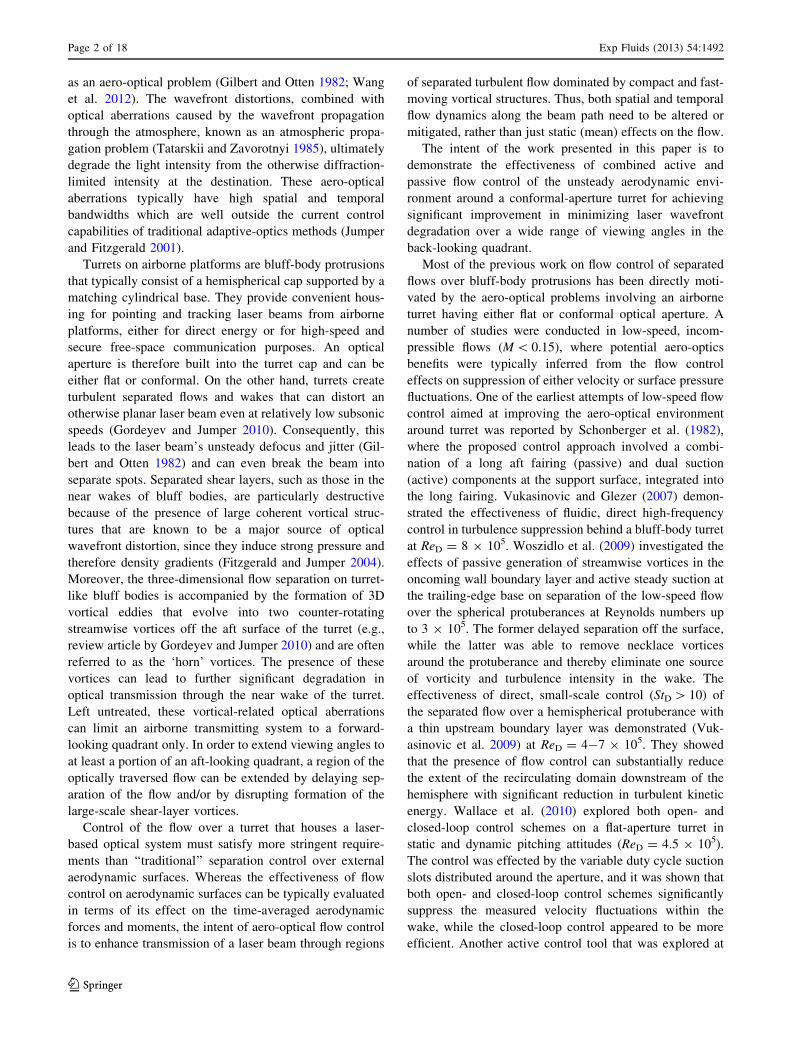
The turret model consists of a D = 0.61 m diameter
hemispherical cap that is supported on a matching cylinder
of H = 0.19 m in height (Fig. 1a). The model is equipped
with a 0.254 m diameter conformal optical aperture/mirror
assembly, which is used for reflection of either the 0.254 m
diameter laser beam of the high-speed 2-D wavefront
sensor or the 1.5 mm Malley Probe laser beams. The lower
section of the cylindrical turret base is stationary, but
allows for rotation of the upper model about the turret’s
zenith plane, thereby positioning the aperture azimuth
angle b. The central hemispherical section between the side
trunnions can also be rotated, providing the adjustment of
the aperture elevation angle a, which is defined as the
angular position of the aperture’s center, relative to the
freestream flow direction. Each combination of the eleva-
tion and azimuth angles constitutes turret attitude (Fig. 1a),
which is denoted in the remainder of this paper as (eleva-
tion, azimuth) in degrees.
Active flow control was effected by arrays of fluidic
oscillating (FO) jets, which operation is based on natural
internal flow instabilities that convert steady air flow at the
inlet to unsteady jets that oscillate in a plane that is defined
by the major axis of the actuator’s exit aperture
(Aj = 4.5 mm 9 1.5 mm). Each actuator aperture was
oriented such that its long side was approximately per-
pendicular to the outer flow when the optical aperture is
located at b = 180� for the center plane tests. When the
optical aperture was oriented off the center plane, the
actuators configuration was altered so that their orientation
relative to the free stream was maintained at b = 136�.
Additional information on the development and charac-
terization of fluidic oscillators can be found in a number of
earlier works (e.g., Gregory et al. 2007). The turret fluidic
oscillating jets were distributed over four control zones, as
shown schematically in Fig. 1b, that could be addressed
individually. The Zone 1 is closest to the aperture and it
was utilized in all of the control scenarios. The next
upstream band of control sources is added for the near-
horizontal elevation angles and is also split in two halves,
labeled as Zone 2 and 3. Lastly, the most upstream segment
is labeled as Zone 4, and it is aimed at the lowest combi-
nations of both elevation and azimuth angles. A total of
180 fluidic oscillator (FO) orifices were distributed across
all control zones: Zone 1 consists of three rows of 30 FOs
(for a total of 90) arranged upstream and around the optical
aperture at angles of 33�, 39�, and 45� from the optical
aperture axis. Zones 2 and 3 each contain two rows of 15
FOs (for a total of 30 each), with the rows located at angles
of 55�, and 65� from optical aperture axis. Zone 4 consists
of 30 FOs, which are positioned in 6 rows. A relative net
mass flow addition to the flow is characterized by the mass
flow rate coefficient Cl, which is defined as a total mass
flow rate through the active jets divided by the tunnel mass
flow rate through the turret frontal cross-sectional area Ao,
and Cl was of the order of 10-3 for all of the control cases
considered. Besides the nominal turret geometry, a modi-
fied geometry included a passive flow control component, a
partition plate (Fig. 1c). A concept of passive alteration of
the global flow topology over a turret by addition of a
partition plate was already explored (Vukasinovic et al.
2011), where its effectiveness was demonstrated in passive
and hybrid flow control configurations. There are two main
reasons for the use of the partition plate as a passive flow
control component. It helps suppressing the turret wake by
displacing the front stagnation line farther downstream
along the hemisphere surface and thereby inducing a
thinner boundary layer and delayed separation on the aft
surface of the hemisphere. In addition, the plate itself
generates a necklace vortex to further assist in diminishing
the effects of flow separation along the hemisphere’s sides.
The present plate’s frontal part is formed by an ellipse
having major and minor axes of 1.8R and 1.5R, respec-
tively, and whose center is displaced by R/6 upstream from
the turret center. The aft segment of the partition plate
wraps around turret at radius 1.5R through b = 120�. The
downstream edge of the partition plate is deflected down-
ward by 10� for 90� \ b\ 120�, thereby creating the aft
lifting surface.
a b c
α
β
0.62
R
+
R/6
1.5R
1.8R
xz
R
Fig. 1 A base turret model
(a) and top-view schematics of
the flow control approaches in
active (b) and passive/hybrid
(c) configurations for the
aperture attitude (a = 30�,
b = 136�). Fluidic oscillating
jet arrays are distributed in
Zone: 1 (black), 2 (red), 3
(blue), and 4 (gray)
Page 4 of 18 Exp Fluids (2013) 54:1492
123
Due to the location of the optical access through the side
windows of the SARL wind tunnel, the model needed to be
elevated 1.25R from the floor of the wind tunnel test sec-
tion in order to be positioned at the azimuth and elevation
angles of interest. Furthermore, in order to maintain
desirable approach boundary layer thickness (d/D \ 0.1),
the turret was mounted on a wall-to-wall plate (ground
board, Fig. 2a). The carried vorticity of such relatively thin
oncoming boundary layer predominantly rolls into a
necklace vortex off the front stagnation line and has only
minor effect on the prevailing dynamics of the separated
flow. The design was guided by CFD simulations (not
shown), which predicted the incoming turbulent boundary
layer of d/D & 0.06. The ground board was 8.75R long
and 5.9R wide and equipped with an adjustable eight-inch
chord trailing-edge flap. Proximity of the board to the
tunnel floor increases the pressure under the board and, left
untreated, would induce a positive flow angle over its
leading edge. Therefore, the flap was positioned during the
initial phase of the testing in order to suppress the nonzero
approach angle of the flow over the plate leading edge. The
flap accelerates the flow under the board to minimize this
approach flow angle. The model is located 3R downstream
from the leading edge of the ground board.
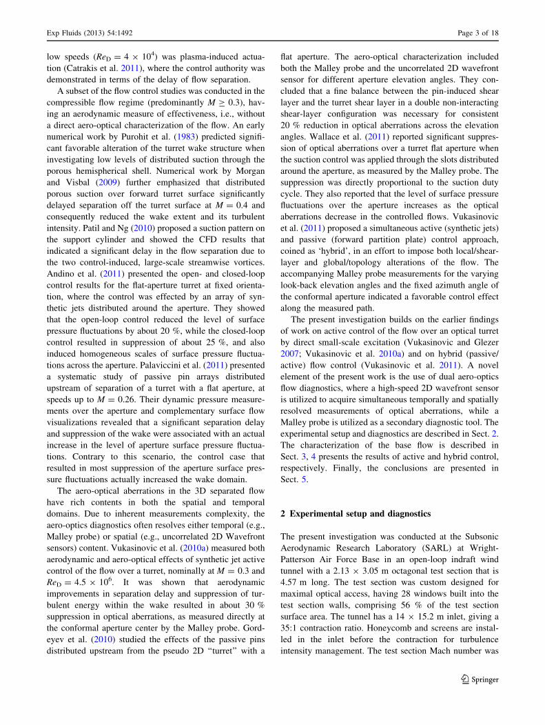
Figure 2 also illustrates all the sensors utilized for the
aerodynamic part of the flow diagnostics, which included
arrays of static pressure ports distributed both on the turret
surface and on the ground board. Two pairs of static
pressure ports were positioned on the upper and lower
leading edge of the ground board, which were used to
elucidate the flow approach angle. Downstream from the
turret, two orthogonal arrays, spanning 1.48 \ x/R \ 2.62
(z/R = 0) and -1.12 \ z/R \ 1.12 (x/R = 1.65), were
aimed at characterization of the characteristic scales of the
resulting wake, where streamwise and spanwise coordi-
nates x and z are measured relative to the turret center. Two
inset plots in Fig. 2 further illustrate two additional static
pressure domains: the flow just upstream from the optical
aperture is characterized by a circumferential array of static
pressure ports wrapped around the optical aperture, while a
9 9 3 surface array of static pressure ports is distributed on
a side of the optical aperture for (segmented) spatial
characterization of the flow as it becomes separated off the
turret surface. Static pressure measurements through
0.5 mm ports were acquired by a Pressure Systems scan-
ner, where the averaged pressure measurement is based on
500 individual samples. Besides the described arrays of
static pressure ports, five dynamic pressure transducers
were also split between the turret and the ground board. In
order to characterize dynamics of the wake over the aper-
ture, three (PD1–PD3) were distributed just downstream
from the aperture (see bottom inset in Fig. 2), while the
remaining two (PD4 and 5) are positioned on the ground
board, just upstream from the expected wake reattachment
zone (Vukasinovic et al. 2011), symmetrically about the
central plane. The dynamic pressures on the ground plane
and the turret were measured through standard 2–3 mm
ports using a PCB 103B01 (3.33 psid) and LQ-125-5D (5
psid) transducers, respectively, that were sampled at
20 kHz, and the mean spectra of pressure fluctuations were
computed using twenty spectra calculated over one-second
subintervals.
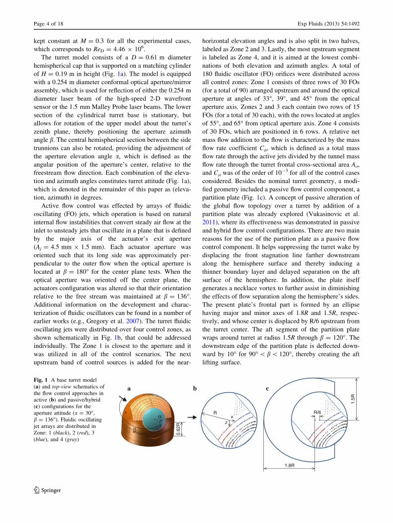
To perform the aero-optical measurements, a 1.2 9 3 m
optical table was attached to the tunnel side wall using
several trusses, schematically shown in Fig. 3. A series of
inner-tube tires were used to isolate the optical table from
high-frequency mechanical oscillations induced by the
tunnel. Optical measurements of 2-D wavefronts over the
aperture of 0.254 m were performed using a high-speed
Shack-Hartmann Wavefront Sensor (WFS). The schematic
of the experimental optical set-up is shown in Fig. 3.
A Nd:YAG laser beam was initially expanded to a
25.4 mm collimated beam and finally was expanded to a
0.254 m round beam using a 1:10 telescope. The beam was
steered to the optical insert mounted on the turret. The
optical insert was designed to reflect the collimated beam
leadingedgestaticports
turret interfacewakedynamicports
wakestaticports
trailingedgeflap
PD4
PD5
-146°
78°
0°
γ
PD1 PD2
PD3
Fig. 2 Streamwise and
spanwise arrays of static
pressure ports and two dynamic
pressure ports (PD4 and PD5)
on the ground board. Two insetplots show schematics of the
array of static pressure ports
upstream from the aperture (top)
and a surface segment covered
by 3 9 9 static pressure ports
and three dynamic pressure
ports (PD1–PD3, bottom)
Exp Fluids (2013) 54:1492 Page 5 of 18
123
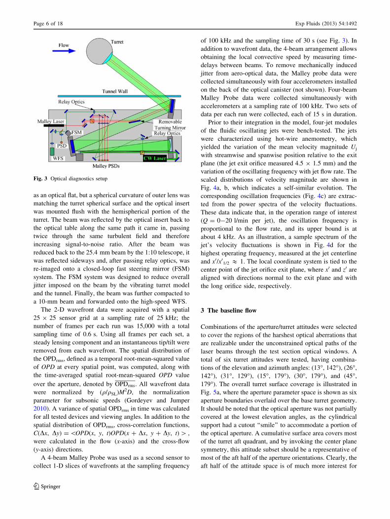
as an optical flat, but a spherical curvature of outer lens was
matching the turret spherical surface and the optical insert
was mounted flush with the hemispherical portion of the
turret. The beam was reflected by the optical insert back to
the optical table along the same path it came in, passing
twice through the same turbulent field and therefore
increasing signal-to-noise ratio. After the beam was
reduced back to the 25.4 mm beam by the 1:10 telescope, it
was reflected sideways and, after passing relay optics, was
re-imaged onto a closed-loop fast steering mirror (FSM)
system. The FSM system was designed to reduce overall
jitter imposed on the beam by the vibrating turret model
and the tunnel. Finally, the beam was further compacted to
a 10-mm beam and forwarded onto the high-speed WFS.
The 2-D wavefront data were acquired with a spatial
25 9 25 sensor grid at a sampling rate of 25 kHz; the
number of frames per each run was 15,000 with a total
sampling time of 0.6 s. Using all frames per each set, a
steady lensing component and an instantaneous tip/tilt were
removed from each wavefront. The spatial distribution of
the OPDrms, defined as a temporal root-mean-squared value
of OPD at every spatial point, was computed, along with
the time-averaged spatial root-mean-squared OPD value
over the aperture, denoted by OPDrms. All wavefront data
were normalized by (q/qSL)M2D, the normalization
parameter for subsonic speeds (Gordeyev and Jumper
2010). A variance of spatial OPDrms in time was calculated
for all tested devices and viewing angles. In addition to the
spatial distribution of OPDrms, cross-correlation functions,
C(Dx, Dy) = \OPD(x, y, t)OPD(x ? Dx, y ? Dy, t) [ ,
were calculated in the flow (x-axis) and the cross-flow
(y-axis) directions.
A 4-beam Malley Probe was used as a second sensor to
collect 1-D slices of wavefronts at the sampling frequency
of 100 kHz and the sampling time of 30 s (see Fig. 3). In
addition to wavefront data, the 4-beam arrangement allows
obtaining the local convective speed by measuring time-
delays between beams. To remove mechanically induced
jitter from aero-optical data, the Malley probe data were
collected simultaneously with four accelerometers installed
on the back of the optical canister (not shown). Four-beam
Malley Probe data were collected simultaneously with
accelerometers at a sampling rate of 100 kHz. Two sets of
data per each run were collected, each of 15 s in duration.
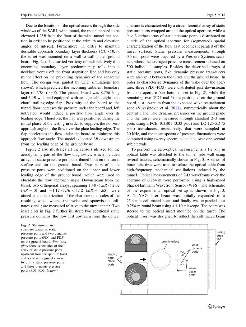
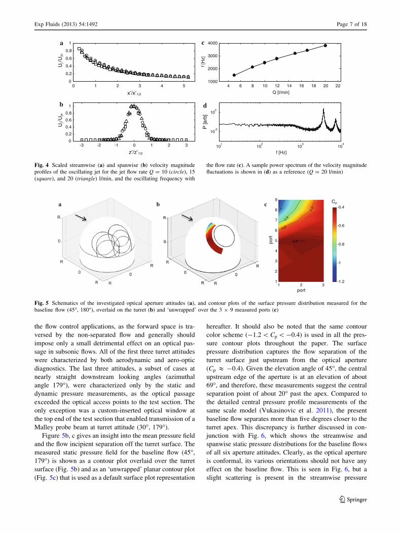
Prior to their integration in the model, four-jet modules
of the fluidic oscillating jets were bench-tested. The jets
were characterized using hot-wire anemometry, which
yielded the variation of the mean velocity magnitude Uj
with streamwise and spanwise position relative to the exit
plane (the jet exit orifice measured 4.5 9 1.5 mm) and the
variation of the oscillating frequency with jet flow rate. The
scaled distributions of velocity magnitude are shown in
Fig. 4a, b, which indicates a self-similar evolution. The
corresponding oscillation frequencies (Fig. 4c) are extrac-
ted from the power spectra of the velocity fluctuations.
These data indicate that, in the operation range of interest
(Q = 0-20 l/min per jet), the oscillation frequency is
proportional to the flow rate, and its upper bound is at
about 4 kHz. As an illustration, a sample spectrum of the
jet’s velocity fluctuations is shown in Fig. 4d for the
highest operating frequency, measured at the jet centerline
and x0/x01/2 & 1. The local coordinate system is tied to the
center point of the jet orifice exit plane, where x0 and z0 are
aligned with directions normal to the exit plane and with
the long orifice side, respectively.
3 The baseline flow
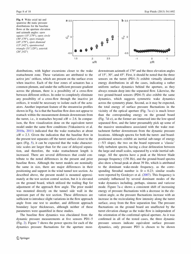
Combinations of the aperture/turret attitudes were selected
to cover the regions of the harshest optical aberrations that
are realizable under the unconstrained optical paths of the
laser beams through the test section optical windows. A
total of six turret attitudes were tested, having combina-
tions of the elevation and azimuth angles: (13�, 142�), (26�,
142�), (31�, 129�), (15�, 179�), (30�, 179�), and (45�,
179�). The overall turret surface coverage is illustrated in
Fig. 5a, where the aperture parameter space is shown as six
aperture boundaries overlaid over the base turret geometry.
It should be noted that the optical aperture was not partially
covered at the lowest elevation angles, as the cylindrical
support had a cutout ‘‘smile’’ to accommodate a portion of
the optical aperture. A cumulative surface area covers most
of the turret aft quadrant, and by invoking the center plane
symmetry, this attitude subset should be a representative of
most of the aft half of the aperture orientations. Clearly, the
aft half of the attitude space is of much more interest for
Fig. 3 Optical diagnostics setup
Page 6 of 18 Exp Fluids (2013) 54:1492
123
the flow control applications, as the forward space is tra-
versed by the non-separated flow and generally should
impose only a small detrimental effect on an optical pas-
sage in subsonic flows. All of the first three turret attitudes
were characterized by both aerodynamic and aero-optic
diagnostics. The last three attitudes, a subset of cases at
nearly straight downstream looking angles (azimuthal
angle 179�), were characterized only by the static and
dynamic pressure measurements, as the optical passage
exceeded the optical access points to the test section. The
only exception was a custom-inserted optical window at
the top end of the test section that enabled transmission of a
Malley probe beam at turret attitude (30�, 179�).
Figure 5b, c gives an insight into the mean pressure field
and the flow incipient separation off the turret surface. The
measured static pressure field for the baseline flow (45�,
179�) is shown as a contour plot overlaid over the turret
surface (Fig. 5b) and as an ‘unwrapped’ planar contour plot
(Fig. 5c) that is used as a default surface plot representation
hereafter. It should also be noted that the same contour
color scheme (-1.2 \ Cp \ -0.4) is used in all the pres-
sure contour plots throughout the paper. The surface
pressure distribution captures the flow separation of the
turret surface just upstream from the optical aperture
(Cp & -0.4). Given the elevation angle of 45�, the central
upstream edge of the aperture is at an elevation of about
69�, and therefore, these measurements suggest the central
separation point of about 20� past the apex. Compared to
the detailed central pressure profile measurements of the
same scale model (Vukasinovic et al. 2011), the present
baseline flow separates more than five degrees closer to the
turret apex. This discrepancy is further discussed in con-
junction with Fig. 6, which shows the streamwise and
spanwise static pressure distributions for the baseline flows
of all six aperture attitudes. Clearly, as the optical aperture
is conformal, its various orientations should not have any
effect on the baseline flow. This is seen in Fig. 6, but a
slight scattering is present in the streamwise pressure
0 1 2 3 4 50
0.2
0.4
0.6
0.8
1
-3 -2 -1 0 1 2 30
0.2
0.4
0.6
0.8
1
a
b
4 6 8 10 12 14 16 18 20 221000
2000
3000
4000
Q [l/min]
f [H
z]
101
102
103
104
10-2
100
f [Hz]
c
d
x’/x’1/2
z’/z’1/2
P [a
rb]
Uj/U
joU
j/U
jo
Fig. 4 Scaled streamwise (a) and spanwise (b) velocity magnitude
profiles of the oscillating jet for the jet flow rate Q = 10 (circle), 15
(square), and 20 (triangle) l/min, and the oscillating frequency with
the flow rate (c). A sample power spectrum of the velocity magnitude
fluctuations is shown in (d) as a reference (Q = 20 l/min)
a cb Cp-0.4
-0.6
-0.8
-1
-1.2
9
8
7
6
5
4
3
2
12 31 1.5 2.5
port
port
Fig. 5 Schematics of the investigated optical aperture attitudes (a), and contour plots of the surface pressure distribution measured for the
baseline flow (45�, 180�), overlaid on the turret (b) and ‘unwrapped’ over the 3 9 9 measured ports (c)
Exp Fluids (2013) 54:1492 Page 7 of 18
123
distributions, with higher excursions closer to the wake
reattachment zone. These variations are attributed to the
active jets’ orifices, which are present on the surface even
when inactive. Each of the four zones of actuators has a
common plenum, and under the sufficient pressure gradient
across the plenum, there is a possibility of a cross-flow
between different orifices. In order to completely eliminate
any possibility of a cross-flow through the inactive jet
orifices, it would be necessary to isolate each of the actu-
ators. Another important feature of the streamwise profiles
shown in Fig. 6a is that the baseline flow does not appear to
reattach within the measurement domain downstream from
the turret, i.e., it reattaches beyond x/R = 2.6. In compar-
ison, the flow visualization done on the equivalent turret
model under the same flow conditions (Vukasinovic et al.
2010a, 2011) indicated that the wake reattaches at about
x/R = 2.3. Given the indication that the baseline flow in
the present test separates off the turret surface closer to the
apex (Fig. 5), it can be expected that the wake character-
istic scales are larger than for the case of delayed separa-
tion, and therefore, the wake reattachment length is
increased. There are several differences that could con-
tribute to the noted differences in the present and prior
baseline flows. Although the turret models are nominally
the same in size, there are major differences in their
positioning and support in the wind tunnel test section. As
described above, the present model is mounted approxi-
mately at the test section central section, but it is elevated
on the ground board, which utilized the trailing flap for
adjustment of the approach flow angle. The prior model
was mounted directly on the tunnel side wall in the
upstream part of the test section. These differences are
sufficient to introduce slight variations in the flow approach
angle from one test to another, and different approach
boundary layer thicknesses, although neither of these
parameters were quantified in these studies.
The baseline flow dynamics was elucidated from the
dynamic pressure measurements at five sensors PD1–5
(Fig. 2). Figure 7 shows the power spectra for each of the
dynamics pressure fluctuations for the aperture most-
downstream azimuth of 179� and the three elevation angles
of 15�, 30�, and 45�. First, it should be noted that the three
sensors on the turret (PD1–3) exhibit virtually identical
energy distributions in all the cases, indicating a rather
uniform surface dynamics behind the aperture, as they
always remain deep into the separated flow. Likewise, the
two ground-board sensors (PD4–5) also exhibit the same
dynamics, which suggests symmetric wake dynamics
across the symmetry plane. Second, as it may be expected,
the total energy of surface pressure fluctuations in the
vicinity of the optical aperture (Fig. 7a–c) is much lower
than the corresponding energy on the ground board
(Fig. 7d–e), as the former are immersed into the low-speed
separated flow, and the latter presumably pick up some of
the massive unsteadiness associated with the wake reat-
tachment further downstream from the dynamic pressure
locations. Although spectra for both the turret- and board-
positioned sensors exhibit an inertial sub-range of energy
(-5/3 slope), the two on the board represent a ‘classic’
fully turbulent spectra, having a clear delineation between
the large and small scales, separated by a wide inertial sub-
range. All the spectra have a peak at the blower blade
passage frequency (156 Hz), and the ground-board spectra
also show a broad peak at about 39 Hz, which is attributed
to the dominant wake-mode frequency, as the corre-
sponding Strouhal number is St = 0.23; similar results
were reported by Gordeyev et al. (2007). This frequency is
certainly influenced by several dominant modes of the
wake dynamics including, perhaps, sinuous and varicose
mode. Figure 7a–c shows a consistent shift of increasing
energy of pressure fluctuations with a decrease in the ele-
vation angle, as the pressure fluctuations increase with an
increase in the recirculating flow intensity along the turret
surface, away from the flow separation line. The pressure
fluctuations on the ground board are unaffected by the
turret elevation change as the wake flow is independent of
the orientation of the conformal optical aperture. As it was
confirmed in all of the tested cases, the three dynamic
pressure sensors indicate equivalent surface pressure
dynamics, only pressure PD3 is chosen to be shown
a b
2.521.5
x/R10-1
z/R
-0.5
0.5
0Cp
-0.5
0.5
0Cp
Fig. 6 Wake axial (a) and
spanwise (b) static pressure
distributions for the baseline
flows at the aperture elevation
and azimuth angles: opensquare (15�,179�), open circle(30�,179�), open triangle(45�,179�), open diamond(13�,142�), openinvertedtriangle (31�,129�), asterisk(26�,142�)
Page 8 of 18 Exp Fluids (2013) 54:1492
123
hereafter, as a representative for the near-aperture dynamics.
Likewise, only PD4 is chosen as a representative for the
pressure dynamics on the ground board.
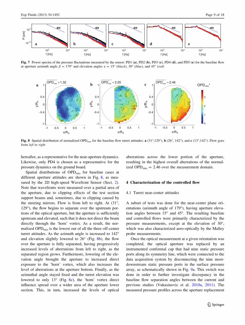
Spatial distributions of OPDrms for baseline cases at
different aperture attitudes are shown in Fig. 8, as mea-
sured by the 2D high-speed Wavefront Sensor (Sect. 2).
Note that wavefronts were measured over a partial area of
the aperture, due to clipping effects of the test section
support beams and, sometimes, due to clipping caused by
the steering mirrors. Flow is from left to right. At (31�,
129�), the flow begins to separate over the upstream por-
tions of the optical aperture, but the aperture is sufficiently
upstream and elevated, such that it does not direct the beam
directly through the ‘horn’ vortex. As a result, the nor-
malized OPDrms is the lowest out of all the three off-center
turret attitudes. As the azimuth angle is increased to 142�and elevation slightly lowered to 26� (Fig. 8b), the flow
over the aperture is fully separated, having progressively
increased levels of aberrations from left to right, as the
separated region grows. Furthermore, lowering of the ele-
vation angle brought the aperture to increased direct
exposure to the ‘horn’ vortex, which also increases the
level of aberrations at the aperture bottom. Finally, as the
azimuthal angle stayed fixed and the turret elevation was
lowered to only 13� (Fig. 8c), the ‘horn’ vortex direct
influence spread over a wider area of the aperture lower
section. This, in turn, increased the levels of optical
aberrations across the lower portion of the aperture,
resulting in the highest overall aberrations of the normal-
ized OPDrms = 2.46 over the measurement domain.
4 Characterization of the controlled flow
4.1 Turret near-center attitudes
A subset of tests was done for the near-center plane ori-
entations (azimuth angle of 179�), having aperture eleva-
tion angles between 15� and 45�. The resulting baseline
and controlled flows were primarily characterized by the
pressure measurements, except at the elevation of 30�,
which was also characterized aero-optically by the Malley
probe measurements.
Once the optical measurement at a given orientation was
completed, the optical aperture was replaced by an
instrumented conformal cap that had nine static pressure
ports along its symmetry line, which were connected to the
data acquisition system by disconnecting the nine most-
downstream static pressure ports in the surface pressure
array, as schematically shown in Fig. 9a. This switch was
done in order to further investigate discrepancy in the
baseline flow separation angles between the current and
previous studies (Vukasinovic et al. 2010a, 2011). The
measured pressure profiles across the aperture replacement
-5/3-5/3-5/3-5/3-5/3-5/3-5/3-5/3-5/3-5/3-5/3-5/3-5/3-5/3-5/3
P [a
rb]
a b c d e
f [Hz]102 104
f [Hz]102 104
f [Hz]102 104
f [Hz]102 104
f [Hz]102 104
10-10
10-5
Fig. 7 Power spectra of the pressure fluctuations measured by the sensor: PD1 (a), PD2 (b), PD3 (c), PD4 (d), and PD5 (e) for the baseline flow
at aperture azimuth angle b = 179� and elevation angles a = 15� (black), 30� (blue), and 45� (red)
1.32OPD*rms = 2.05OPD*
rms = 2.46OPD*rms =
a b c OPDrms*
-1 -0.5 0 0.5 1
x/RA
1
0
-1
0.4
-0.4
y/R
A
3
2
1
0
-1 -0.5 0 0.5 1
x/RA
-1 -0.5 0 0.5 1
x/RA
1
0
-1
0.4
-0.4
y/R
A
1
0
-1
0.4
-0.4
y/R
A
Fig. 8 Spatial distribution of normalized OPDrms for the baseline flow turret attitudes: a (31�,129�), b (26�, 142�), and c (13�,142�). Flow goes
from left to right
Exp Fluids (2013) 54:1492 Page 9 of 18
123
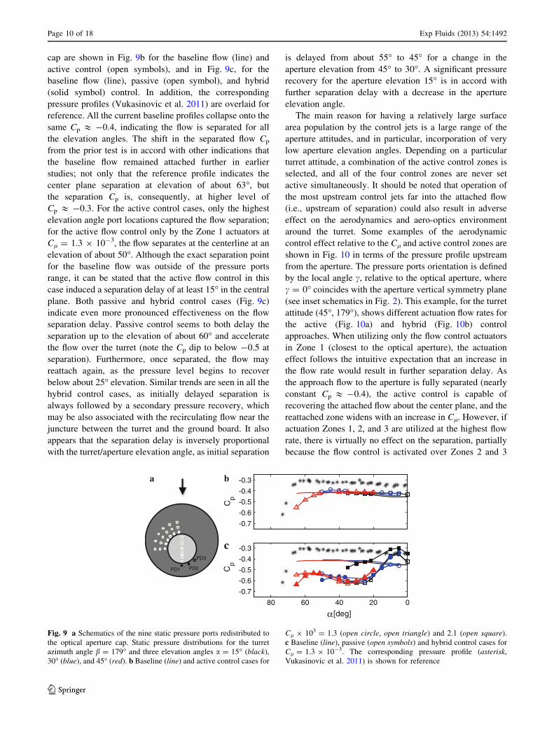
cap are shown in Fig. 9b for the baseline flow (line) and
active control (open symbols), and in Fig. 9c, for the
baseline flow (line), passive (open symbol), and hybrid
(solid symbol) control. In addition, the corresponding
pressure profiles (Vukasinovic et al. 2011) are overlaid for
reference. All the current baseline profiles collapse onto the
same Cp & -0.4, indicating the flow is separated for all
the elevation angles. The shift in the separated flow Cp
from the prior test is in accord with other indications that
the baseline flow remained attached further in earlier
studies; not only that the reference profile indicates the
center plane separation at elevation of about 63�, but
the separation Cp is, consequently, at higher level of
Cp & -0.3. For the active control cases, only the highest
elevation angle port locations captured the flow separation;
for the active flow control only by the Zone 1 actuators at
Cl = 1.3 9 10-3, the flow separates at the centerline at an
elevation of about 50�. Although the exact separation point
for the baseline flow was outside of the pressure ports
range, it can be stated that the active flow control in this
case induced a separation delay of at least 15� in the central
plane. Both passive and hybrid control cases (Fig. 9c)
indicate even more pronounced effectiveness on the flow
separation delay. Passive control seems to both delay the
separation up to the elevation of about 60� and accelerate
the flow over the turret (note the Cp dip to below -0.5 at
separation). Furthermore, once separated, the flow may
reattach again, as the pressure level begins to recover
below about 25� elevation. Similar trends are seen in all the
hybrid control cases, as initially delayed separation is
always followed by a secondary pressure recovery, which
may be also associated with the recirculating flow near the
juncture between the turret and the ground board. It also
appears that the separation delay is inversely proportional
with the turret/aperture elevation angle, as initial separation
is delayed from about 55� to 45� for a change in the
aperture elevation from 45� to 30�. A significant pressure
recovery for the aperture elevation 15� is in accord with
further separation delay with a decrease in the aperture
elevation angle.
The main reason for having a relatively large surface
area population by the control jets is a large range of the
aperture attitudes, and in particular, incorporation of very
low aperture elevation angles. Depending on a particular
turret attitude, a combination of the active control zones is
selected, and all of the four control zones are never set
active simultaneously. It should be noted that operation of
the most upstream control jets far into the attached flow
(i.e., upstream of separation) could also result in adverse
effect on the aerodynamics and aero-optics environment
around the turret. Some examples of the aerodynamic
control effect relative to the Cl and active control zones are
shown in Fig. 10 in terms of the pressure profile upstream
from the aperture. The pressure ports orientation is defined
by the local angle c, relative to the optical aperture, where
c = 0� coincides with the aperture vertical symmetry plane
(see inset schematics in Fig. 2). This example, for the turret
attitude (45�, 179�), shows different actuation flow rates for
the active (Fig. 10a) and hybrid (Fig. 10b) control
approaches. When utilizing only the flow control actuators
in Zone 1 (closest to the optical aperture), the actuation
effect follows the intuitive expectation that an increase in
the flow rate would result in further separation delay. As
the approach flow to the aperture is fully separated (nearly
constant Cp & -0.4), the active control is capable of
recovering the attached flow about the center plane, and the
reattached zone widens with an increase in Cl. However, if
actuation Zones 1, 2, and 3 are utilized at the highest flow
rate, there is virtually no effect on the separation, partially
because the flow control is activated over Zones 2 and 3
-0.7
-0.6
-0.5
-0.4
-0.3
Cp
a b
020406080
-0.7
-0.6
-0.5
-0.4
-0.3
[deg]
Cp
α
PD1 PD2
PD3
c
Fig. 9 a Schematics of the nine static pressure ports redistributed to
the optical aperture cap. Static pressure distributions for the turret
azimuth angle b = 179� and three elevation angles a = 15� (black),
30� (blue), and 45� (red). b Baseline (line) and active control cases for
Cl 9 103 = 1.3 (open circle, open triangle) and 2.1 (open square).
c Baseline (line), passive (open symbols) and hybrid control cases for
Cl = 1.3 9 10-3. The corresponding pressure profile (asterisk,
Vukasinovic et al. 2011) is shown for reference
Page 10 of 18 Exp Fluids (2013) 54:1492
123
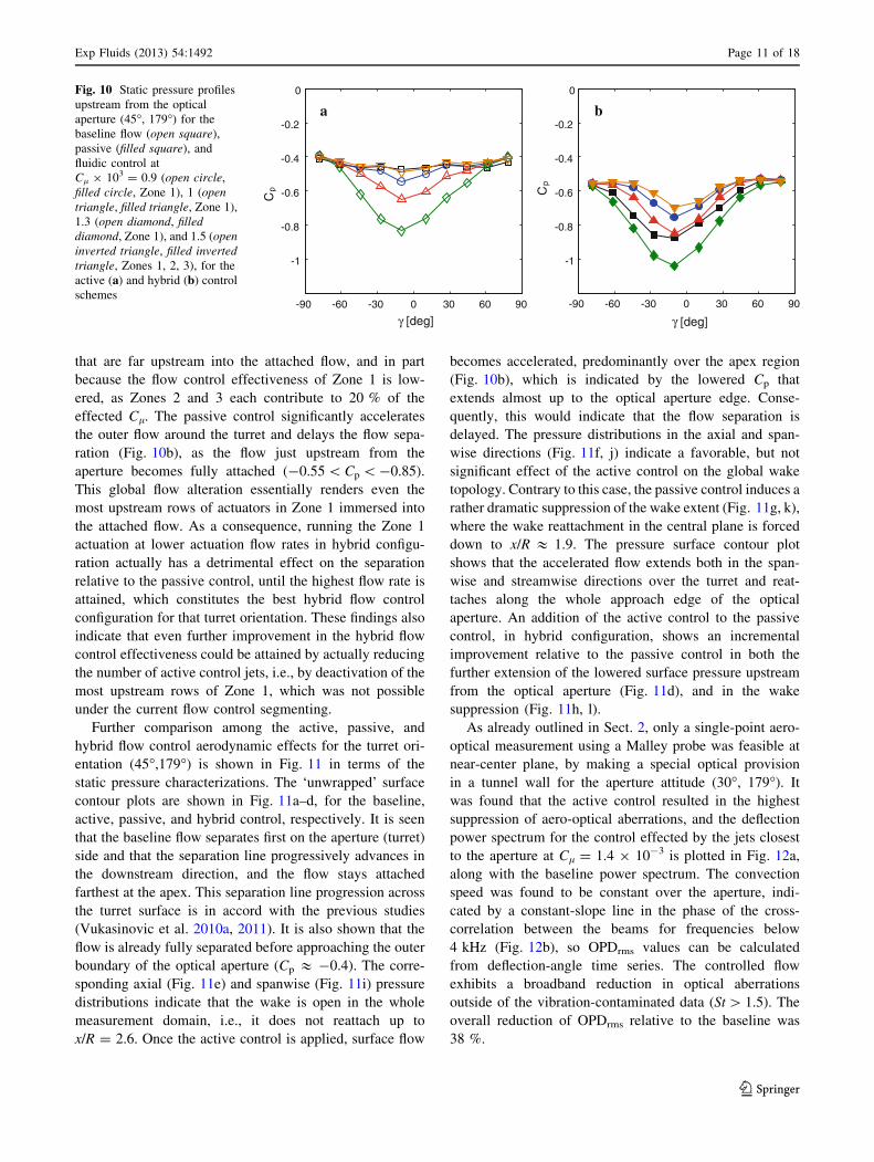
that are far upstream into the attached flow, and in part
because the flow control effectiveness of Zone 1 is low-
ered, as Zones 2 and 3 each contribute to 20 % of the
effected Cl. The passive control significantly accelerates
the outer flow around the turret and delays the flow sepa-
ration (Fig. 10b), as the flow just upstream from the
aperture becomes fully attached (-0.55 \ Cp \ -0.85).
This global flow alteration essentially renders even the
most upstream rows of actuators in Zone 1 immersed into
the attached flow. As a consequence, running the Zone 1
actuation at lower actuation flow rates in hybrid configu-
ration actually has a detrimental effect on the separation
relative to the passive control, until the highest flow rate is
attained, which constitutes the best hybrid flow control
configuration for that turret orientation. These findings also
indicate that even further improvement in the hybrid flow
control effectiveness could be attained by actually reducing
the number of active control jets, i.e., by deactivation of the
most upstream rows of Zone 1, which was not possible
under the current flow control segmenting.
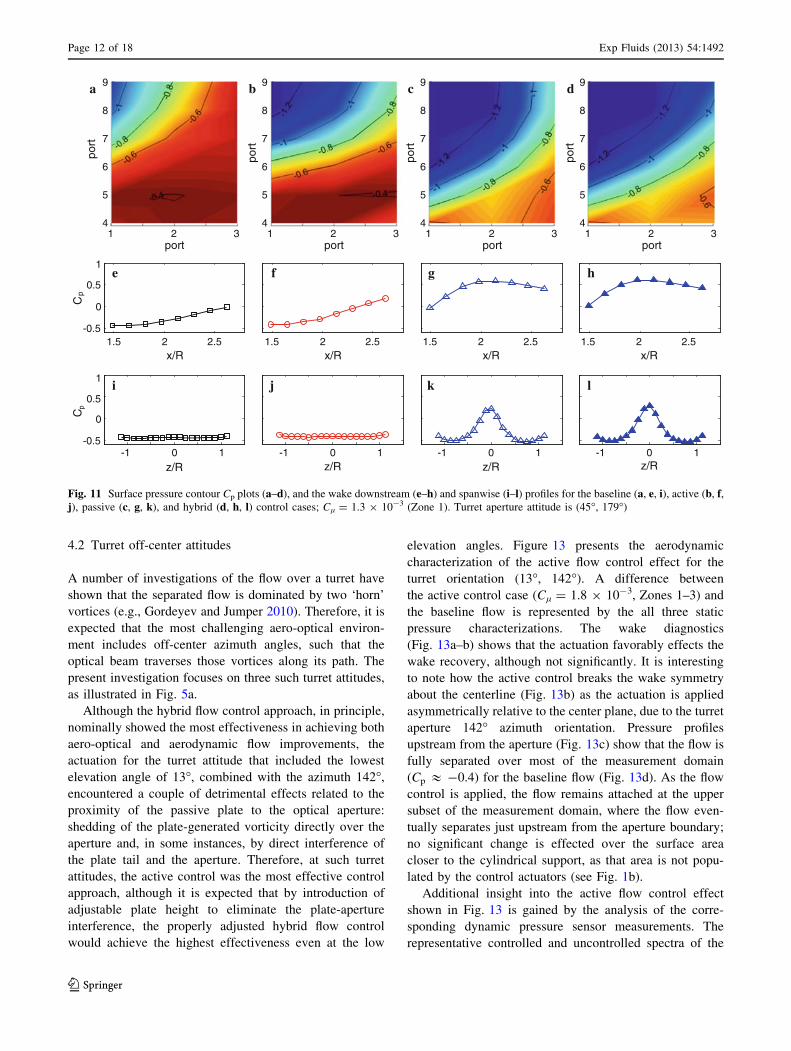
Further comparison among the active, passive, and
hybrid flow control aerodynamic effects for the turret ori-
entation (45�,179�) is shown in Fig. 11 in terms of the
static pressure characterizations. The ‘unwrapped’ surface
contour plots are shown in Fig. 11a–d, for the baseline,
active, passive, and hybrid control, respectively. It is seen
that the baseline flow separates first on the aperture (turret)
side and that the separation line progressively advances in
the downstream direction, and the flow stays attached
farthest at the apex. This separation line progression across
the turret surface is in accord with the previous studies
(Vukasinovic et al. 2010a, 2011). It is also shown that the
flow is already fully separated before approaching the outer
boundary of the optical aperture (Cp & -0.4). The corre-
sponding axial (Fig. 11e) and spanwise (Fig. 11i) pressure
distributions indicate that the wake is open in the whole
measurement domain, i.e., it does not reattach up to
x/R = 2.6. Once the active control is applied, surface flow
becomes accelerated, predominantly over the apex region
(Fig. 10b), which is indicated by the lowered Cp that
extends almost up to the optical aperture edge. Conse-
quently, this would indicate that the flow separation is
delayed. The pressure distributions in the axial and span-
wise directions (Fig. 11f, j) indicate a favorable, but not
significant effect of the active control on the global wake
topology. Contrary to this case, the passive control induces a
rather dramatic suppression of the wake extent (Fig. 11g, k),
where the wake reattachment in the central plane is forced
down to x/R & 1.9. The pressure surface contour plot
shows that the accelerated flow extends both in the span-
wise and streamwise directions over the turret and reat-
taches along the whole approach edge of the optical
aperture. An addition of the active control to the passive
control, in hybrid configuration, shows an incremental
improvement relative to the passive control in both the
further extension of the lowered surface pressure upstream
from the optical aperture (Fig. 11d), and in the wake
suppression (Fig. 11h, l).
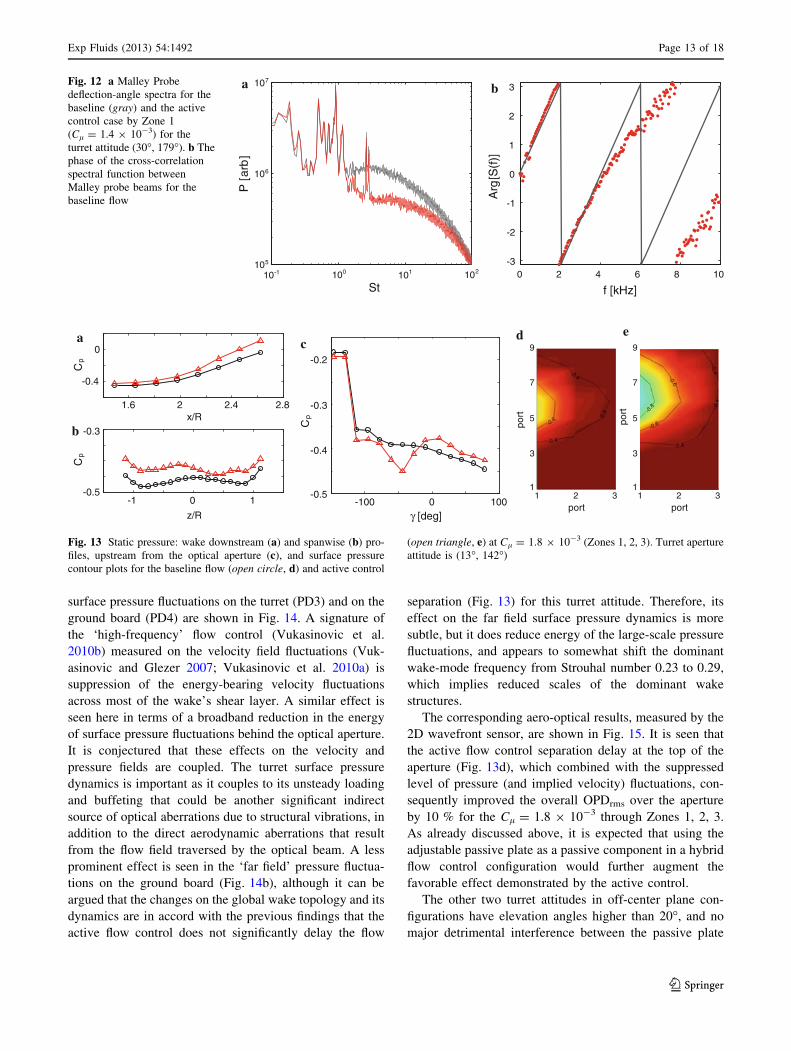
As already outlined in Sect. 2, only a single-point aero-
optical measurement using a Malley probe was feasible at
near-center plane, by making a special optical provision
in a tunnel wall for the aperture attitude (30�, 179�). It
was found that the active control resulted in the highest
suppression of aero-optical aberrations, and the deflection
power spectrum for the control effected by the jets closest
to the aperture at Cl = 1.4 9 10-3 is plotted in Fig. 12a,
along with the baseline power spectrum. The convection
speed was found to be constant over the aperture, indi-
cated by a constant-slope line in the phase of the cross-
correlation between the beams for frequencies below
4 kHz (Fig. 12b), so OPDrms values can be calculated
from deflection-angle time series. The controlled flow
exhibits a broadband reduction in optical aberrations
outside of the vibration-contaminated data (St [ 1.5). The
overall reduction of OPDrms relative to the baseline was
38 %.
a b-0.2
-0.4
-0.6
-0.8
-1
0
Cp
-0.2
-0.4
-0.6
-0.8
-1
0
Cp
-90 -60 -30 0 30 60 90
γ [deg]-90 -60 -30 0 30 60 90
γ [deg]
Fig. 10 Static pressure profiles
upstream from the optical
aperture (45�, 179�) for the
baseline flow (open square),
passive (filled square), and
fluidic control at
Cl 9 103 = 0.9 (open circle,
filled circle, Zone 1), 1 (opentriangle, filled triangle, Zone 1),
1.3 (open diamond, filleddiamond, Zone 1), and 1.5 (openinverted triangle, filled invertedtriangle, Zones 1, 2, 3), for the
active (a) and hybrid (b) control
schemes
Exp Fluids (2013) 54:1492 Page 11 of 18
123
4.2 Turret off-center attitudes
A number of investigations of the flow over a turret have
shown that the separated flow is dominated by two ‘horn’
vortices (e.g., Gordeyev and Jumper 2010). Therefore, it is
expected that the most challenging aero-optical environ-
ment includes off-center azimuth angles, such that the
optical beam traverses those vortices along its path. The
present investigation focuses on three such turret attitudes,
as illustrated in Fig. 5a.
Although the hybrid flow control approach, in principle,
nominally showed the most effectiveness in achieving both
aero-optical and aerodynamic flow improvements, the
actuation for the turret attitude that included the lowest
elevation angle of 13�, combined with the azimuth 142�,
encountered a couple of detrimental effects related to the
proximity of the passive plate to the optical aperture:
shedding of the plate-generated vorticity directly over the
aperture and, in some instances, by direct interference of
the plate tail and the aperture. Therefore, at such turret
attitudes, the active control was the most effective control
approach, although it is expected that by introduction of
adjustable plate height to eliminate the plate-aperture
interference, the properly adjusted hybrid flow control
would achieve the highest effectiveness even at the low
elevation angles. Figure 13 presents the aerodynamic
characterization of the active flow control effect for the
turret orientation (13�, 142�). A difference between
the active control case (Cl = 1.8 9 10-3, Zones 1–3) and
the baseline flow is represented by the all three static
pressure characterizations. The wake diagnostics
(Fig. 13a–b) shows that the actuation favorably effects the
wake recovery, although not significantly. It is interesting
to note how the active control breaks the wake symmetry
about the centerline (Fig. 13b) as the actuation is applied
asymmetrically relative to the center plane, due to the turret
aperture 142� azimuth orientation. Pressure profiles
upstream from the aperture (Fig. 13c) show that the flow is
fully separated over most of the measurement domain
(Cp & -0.4) for the baseline flow (Fig. 13d). As the flow
control is applied, the flow remains attached at the upper
subset of the measurement domain, where the flow even-
tually separates just upstream from the aperture boundary;
no significant change is effected over the surface area
closer to the cylindrical support, as that area is not popu-
lated by the control actuators (see Fig. 1b).
Additional insight into the active flow control effect
shown in Fig. 13 is gained by the analysis of the corre-
sponding dynamic pressure sensor measurements. The
representative controlled and uncontrolled spectra of the
p
a b c d
e f g h
i j k l
9
8
7
6
5
42 31
port
port
9
8
7
6
5
42 31
portpo
rt
9
8
7
6
5
42 31
port
port
9
8
7
6
5
42 31
port
port
1.5 2 2.5x/R
1.5 2 2.5x/R
1.5 2 2.5x/R
1.5 2 2.5x/R
1
0.5
-0.5
0Cp
z/R-1 0 1
z/R-1 0 1
z/R-1 0 1
z/R-1 0 1
1
0.5
-0.5
0C
Fig. 11 Surface pressure contour Cp plots (a–d), and the wake downstream (e–h) and spanwise (i–l) profiles for the baseline (a, e, i), active (b, f,j), passive (c, g, k), and hybrid (d, h, l) control cases; Cl = 1.3 9 10-3 (Zone 1). Turret aperture attitude is (45�, 179�)
Page 12 of 18 Exp Fluids (2013) 54:1492
123
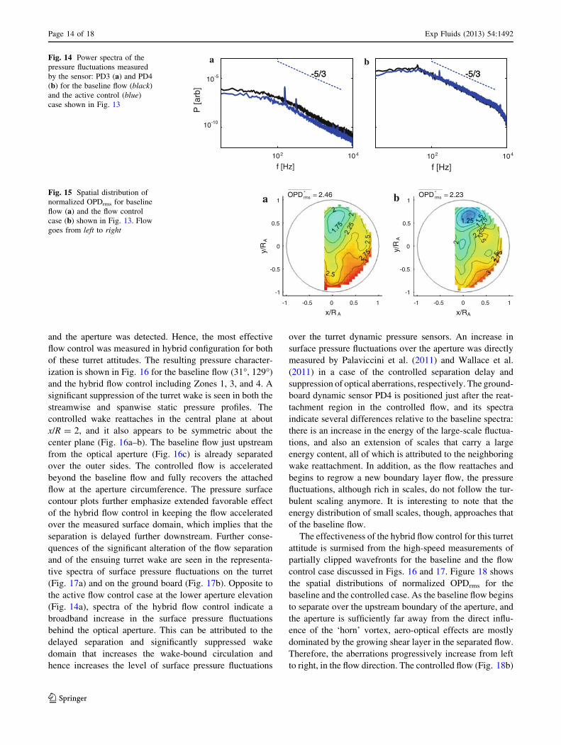
surface pressure fluctuations on the turret (PD3) and on the
ground board (PD4) are shown in Fig. 14. A signature of
the ‘high-frequency’ flow control (Vukasinovic et al.
2010b) measured on the velocity field fluctuations (Vuk-
asinovic and Glezer 2007; Vukasinovic et al. 2010a) is
suppression of the energy-bearing velocity fluctuations
across most of the wake’s shear layer. A similar effect is
seen here in terms of a broadband reduction in the energy
of surface pressure fluctuations behind the optical aperture.
It is conjectured that these effects on the velocity and
pressure fields are coupled. The turret surface pressure
dynamics is important as it couples to its unsteady loading
and buffeting that could be another significant indirect
source of optical aberrations due to structural vibrations, in
addition to the direct aerodynamic aberrations that result
from the flow field traversed by the optical beam. A less
prominent effect is seen in the ‘far field’ pressure fluctua-
tions on the ground board (Fig. 14b), although it can be
argued that the changes on the global wake topology and its
dynamics are in accord with the previous findings that the
active flow control does not significantly delay the flow
separation (Fig. 13) for this turret attitude. Therefore, its
effect on the far field surface pressure dynamics is more
subtle, but it does reduce energy of the large-scale pressure
fluctuations, and appears to somewhat shift the dominant
wake-mode frequency from Strouhal number 0.23 to 0.29,
which implies reduced scales of the dominant wake
structures.
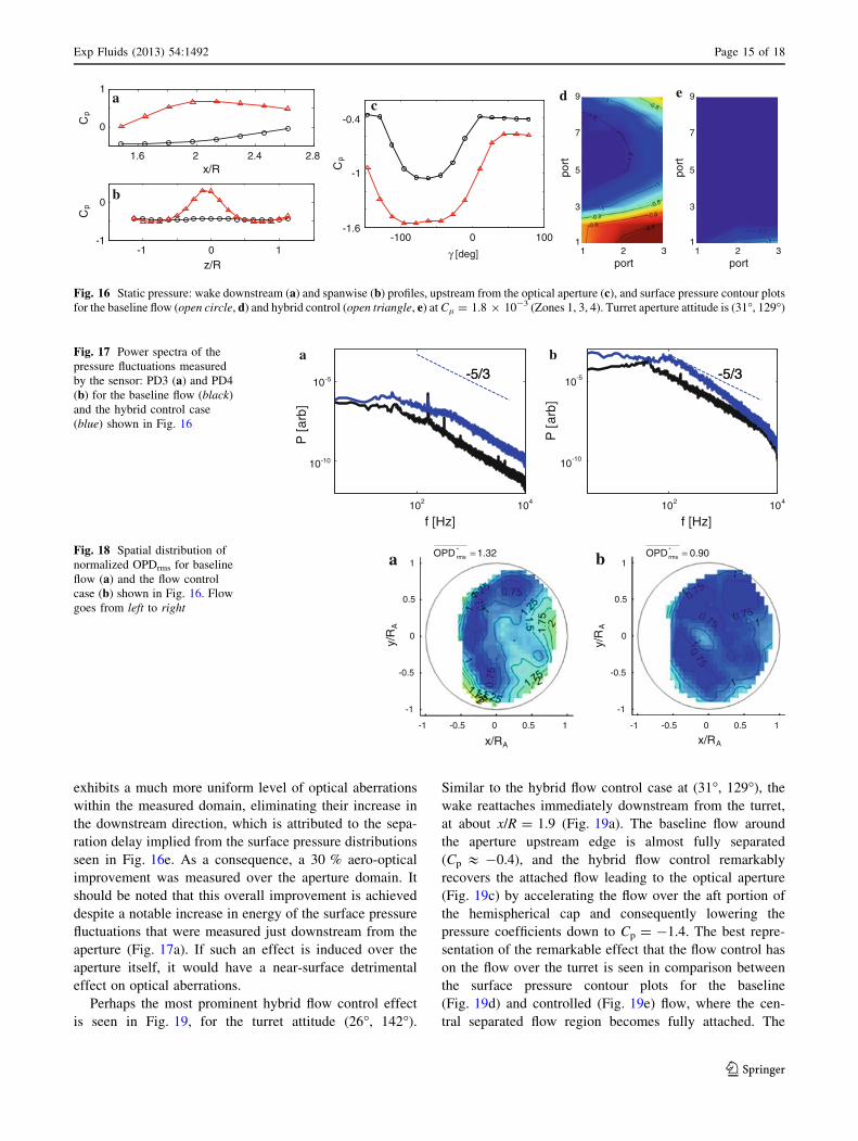
The corresponding aero-optical results, measured by the
2D wavefront sensor, are shown in Fig. 15. It is seen that
the active flow control separation delay at the top of the
aperture (Fig. 13d), which combined with the suppressed
level of pressure (and implied velocity) fluctuations, con-
sequently improved the overall OPDrms over the aperture
by 10 % for the Cl = 1.8 9 10-3 through Zones 1, 2, 3.
As already discussed above, it is expected that using the
adjustable passive plate as a passive component in a hybrid
flow control configuration would further augment the
favorable effect demonstrated by the active control.
The other two turret attitudes in off-center plane con-
figurations have elevation angles higher than 20�, and no
major detrimental interference between the passive plate
a c
b
z/R
-1 0 1
-0.4
0
Cp
-0.3
Cp
-0.5
1.6 2 2.4 2.8x/R
-100 1000γ [deg]
-0.3
Cp
-0.5
-0.4
-0.29
7
5
3
131
port2
port
d9
7
5
3
131
port2
port
e
Fig. 13 Static pressure: wake downstream (a) and spanwise (b) pro-
files, upstream from the optical aperture (c), and surface pressure
contour plots for the baseline flow (open circle, d) and active control
(open triangle, e) at Cl = 1.8 9 10-3 (Zones 1, 2, 3). Turret aperture
attitude is (13�, 142�)
100 10110-1 102
St
105
106
107
P [
arb
]
0 2 4 6 8 10
f [kHz]
Arg
[S(f
)]
0
1
2
3
-3
-2
-1
baFig. 12 a Malley Probe
deflection-angle spectra for the
baseline (gray) and the active
control case by Zone 1
(Cl = 1.4 9 10-3) for the
turret attitude (30�, 179�). b The
phase of the cross-correlation
spectral function between
Malley probe beams for the
baseline flow
Exp Fluids (2013) 54:1492 Page 13 of 18
123
and the aperture was detected. Hence, the most effective
flow control was measured in hybrid configuration for both
of these turret attitudes. The resulting pressure character-
ization is shown in Fig. 16 for the baseline flow (31�, 129�)
and the hybrid flow control including Zones 1, 3, and 4. A
significant suppression of the turret wake is seen in both the
streamwise and spanwise static pressure profiles. The
controlled wake reattaches in the central plane at about
x/R = 2, and it also appears to be symmetric about the
center plane (Fig. 16a–b). The baseline flow just upstream
from the optical aperture (Fig. 16c) is already separated
over the outer sides. The controlled flow is accelerated
beyond the baseline flow and fully recovers the attached
flow at the aperture circumference. The pressure surface
contour plots further emphasize extended favorable effect
of the hybrid flow control in keeping the flow accelerated
over the measured surface domain, which implies that the
separation is delayed further downstream. Further conse-
quences of the significant alteration of the flow separation
and of the ensuing turret wake are seen in the representa-
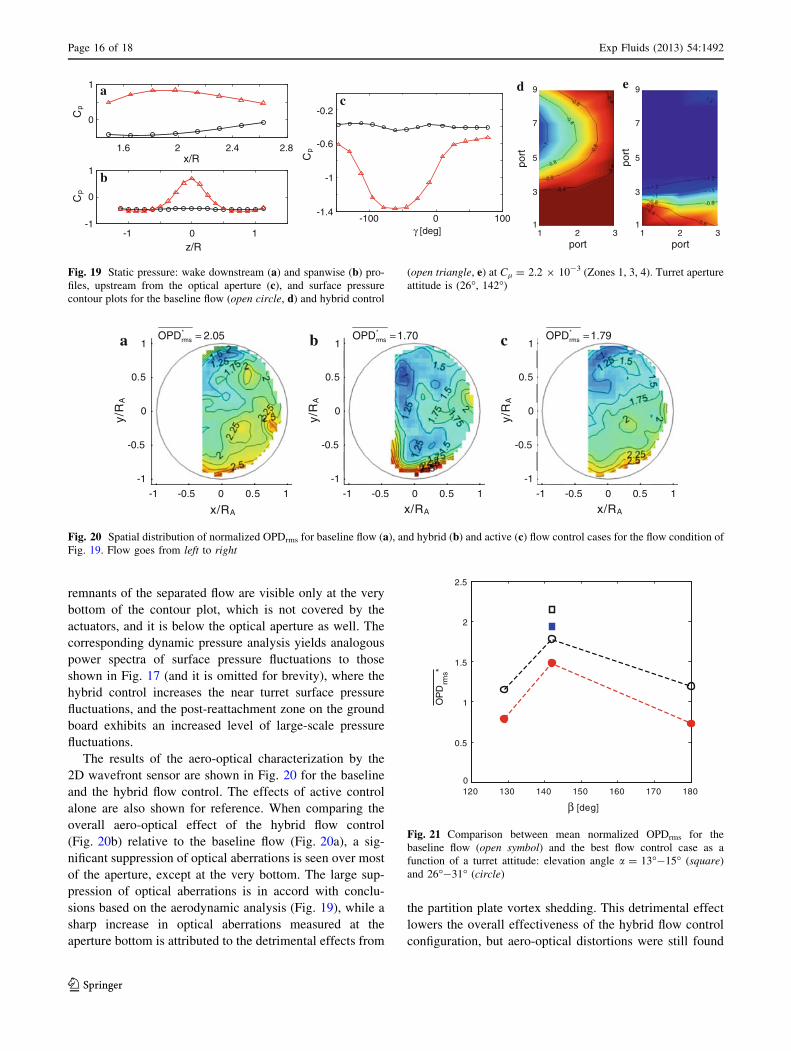
tive spectra of surface pressure fluctuations on the turret
(Fig. 17a) and on the ground board (Fig. 17b). Opposite to
the active flow control case at the lower aperture elevation
(Fig. 14a), spectra of the hybrid flow control indicate a
broadband increase in the surface pressure fluctuations
behind the optical aperture. This can be attributed to the
delayed separation and significantly suppressed wake
domain that increases the wake-bound circulation and
hence increases the level of surface pressure fluctuations
over the turret dynamic pressure sensors. An increase in
surface pressure fluctuations over the aperture was directly
measured by Palaviccini et al. (2011) and Wallace et al.
(2011) in a case of the controlled separation delay and
suppression of optical aberrations, respectively. The ground-
board dynamic sensor PD4 is positioned just after the reat-
tachment region in the controlled flow, and its spectra
indicate several differences relative to the baseline spectra:
there is an increase in the energy of the large-scale fluctua-
tions, and also an extension of scales that carry a large
energy content, all of which is attributed to the neighboring
wake reattachment. In addition, as the flow reattaches and
begins to regrow a new boundary layer flow, the pressure
fluctuations, although rich in scales, do not follow the tur-
bulent scaling anymore. It is interesting to note that the
energy distribution of small scales, though, approaches that
of the baseline flow.
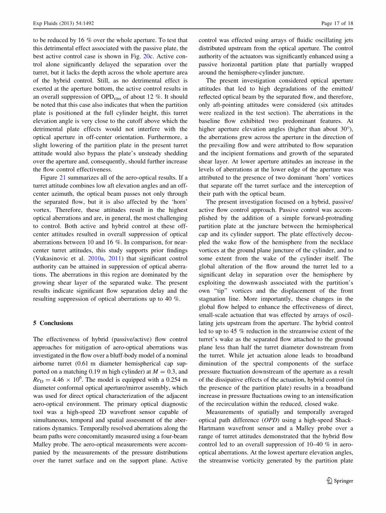
The effectiveness of the hybrid flow control for this turret
attitude is surmised from the high-speed measurements of
partially clipped wavefronts for the baseline and the flow
control case discussed in Figs. 16 and 17. Figure 18 shows
the spatial distributions of normalized OPDrms for the
baseline and the controlled case. As the baseline flow begins
to separate over the upstream boundary of the aperture, and
the aperture is sufficiently far away from the direct influ-
ence of the ‘horn’ vortex, aero-optical effects are mostly
dominated by the growing shear layer in the separated flow.
Therefore, the aberrations progressively increase from left
to right, in the flow direction. The controlled flow (Fig. 18b)
-5/3-5/3-5/3-5/3
a b
P [a
rb]
f [Hz]102 104
10-10
10-5
f [Hz]102 104
Fig. 14 Power spectra of the
pressure fluctuations measured
by the sensor: PD3 (a) and PD4
(b) for the baseline flow (black)
and the active control (blue)
case shown in Fig. 13
2.46OPD*rms = 2.23OPD*
rms =a b
-1 -0.5 0 0.5 1
x/R A
1
0
-1
0.5
-0.5y/
RA
-1 -0.5 0 0.5 1
x/RA
1
0
-1
0.5
-0.5
y/R
A
Fig. 15 Spatial distribution of
normalized OPDrms for baseline
flow (a) and the flow control
case (b) shown in Fig. 13. Flow
goes from left to right
Page 14 of 18 Exp Fluids (2013) 54:1492
123
exhibits a much more uniform level of optical aberrations
within the measured domain, eliminating their increase in
the downstream direction, which is attributed to the sepa-
ration delay implied from the surface pressure distributions
seen in Fig. 16e. As a consequence, a 30 % aero-optical
improvement was measured over the aperture domain. It
should be noted that this overall improvement is achieved
despite a notable increase in energy of the surface pressure
fluctuations that were measured just downstream from the
aperture (Fig. 17a). If such an effect is induced over the
aperture itself, it would have a near-surface detrimental
effect on optical aberrations.
Perhaps the most prominent hybrid flow control effect
is seen in Fig. 19, for the turret attitude (26�, 142�).
Similar to the hybrid flow control case at (31�, 129�), the
wake reattaches immediately downstream from the turret,
at about x/R = 1.9 (Fig. 19a). The baseline flow around
the aperture upstream edge is almost fully separated
(Cp & -0.4), and the hybrid flow control remarkably
recovers the attached flow leading to the optical aperture
(Fig. 19c) by accelerating the flow over the aft portion of
the hemispherical cap and consequently lowering the
pressure coefficients down to Cp = -1.4. The best repre-
sentation of the remarkable effect that the flow control has
on the flow over the turret is seen in comparison between
the surface pressure contour plots for the baseline
(Fig. 19d) and controlled (Fig. 19e) flow, where the cen-
tral separated flow region becomes fully attached. The
-5/3-5/3b
-5/3-5/3a
f [Hz]102 104
P [
arb]
10-10
10-5
f [Hz]102 104
P [
arb]
10-10
10-5
Fig. 17 Power spectra of the
pressure fluctuations measured
by the sensor: PD3 (a) and PD4
(b) for the baseline flow (black)
and the hybrid control case
(blue) shown in Fig. 16
1.32OPD *rms = 0.90OPD*
rms =a b
-1 -0.5 0 0.5 1
x/RA
1
0
-1
0.5
-0.5
y/R
A
-1 -0.5 0 0.5 1
x/RA
1
0
-1
0.5
-0.5
y/R
A
Fig. 18 Spatial distribution of
normalized OPDrms for baseline
flow (a) and the flow control
case (b) shown in Fig. 16. Flow
goes from left to right
a
b
c1
0
0
Cp
Cp
1.6 2 2.4 2.8x/R
z/R-1 0 1
-1 -100 100
γ [deg]
0
9
7
5
3
131
port2
port
9
7
5
3
131
port2
port
ed
-0.4
-1.6
-1
Cp
Fig. 16 Static pressure: wake downstream (a) and spanwise (b) profiles, upstream from the optical aperture (c), and surface pressure contour plots
for the baseline flow (open circle, d) and hybrid control (open triangle, e) at Cl = 1.8 9 10-3 (Zones 1, 3, 4). Turret aperture attitude is (31�, 129�)
Exp Fluids (2013) 54:1492 Page 15 of 18
123
remnants of the separated flow are visible only at the very
bottom of the contour plot, which is not covered by the
actuators, and it is below the optical aperture as well. The
corresponding dynamic pressure analysis yields analogous
power spectra of surface pressure fluctuations to those
shown in Fig. 17 (and it is omitted for brevity), where the
hybrid control increases the near turret surface pressure
fluctuations, and the post-reattachment zone on the ground
board exhibits an increased level of large-scale pressure
fluctuations.
The results of the aero-optical characterization by the
2D wavefront sensor are shown in Fig. 20 for the baseline
and the hybrid flow control. The effects of active control
alone are also shown for reference. When comparing the
overall aero-optical effect of the hybrid flow control
(Fig. 20b) relative to the baseline flow (Fig. 20a), a sig-
nificant suppression of optical aberrations is seen over most
of the aperture, except at the very bottom. The large sup-
pression of optical aberrations is in accord with conclu-
sions based on the aerodynamic analysis (Fig. 19), while a
sharp increase in optical aberrations measured at the
aperture bottom is attributed to the detrimental effects from
the partition plate vortex shedding. This detrimental effect
lowers the overall effectiveness of the hybrid flow control
configuration, but aero-optical distortions were still found
a
b
c
1
1
0
0
Cp
Cp
1.6 2 2.4 2.8x/R
z/R-1 0 1
-1
-0.2
-1
-0.6
-100 100γ [deg]
0
Cp
-1.4
9
7
5
3
131
port2
port
9
7
5
3
131
port2
port
ed
Fig. 19 Static pressure: wake downstream (a) and spanwise (b) pro-
files, upstream from the optical aperture (c), and surface pressure
contour plots for the baseline flow (open circle, d) and hybrid control
(open triangle, e) at Cl = 2.2 9 10-3 (Zones 1, 3, 4). Turret aperture
attitude is (26�, 142�)
2.05OPD*rms = 1.70OPD*
rms = 1.79OPD*rms =a b c
-1 -0.5 0 0.5 1
x/RA
1
0
-1
0.5
-0.5
y/R
A
-1 -0.5 0 0.5 1
x/RA
1
0
-1
0.5
-0.5
y/R
A
-1 -0.5 0 0.5 1
x/RA
1
0
-1
0.5
-0.5
y/R
A
Fig. 20 Spatial distribution of normalized OPDrms for baseline flow (a), and hybrid (b) and active (c) flow control cases for the flow condition of
Fig. 19. Flow goes from left to right
120 130 140 150 160 170 1800
0.5
1
1.5
2
2.5
[deg]
OP
Drm
s*
β
Fig. 21 Comparison between mean normalized OPDrms for the
baseline flow (open symbol) and the best flow control case as a
function of a turret attitude: elevation angle a = 13�-15� (square)
and 26�-31� (circle)
Page 16 of 18 Exp Fluids (2013) 54:1492
123
to be reduced by 16 % over the whole aperture. To test that
this detrimental effect associated with the passive plate, the
best active control case is shown in Fig. 20c. Active con-
trol alone significantly delayed the separation over the
turret, but it lacks the depth across the whole aperture area
of the hybrid control. Still, as no detrimental effect is
exerted at the aperture bottom, the active control results in
an overall suppression of OPDrms of about 12 %. It should
be noted that this case also indicates that when the partition
plate is positioned at the full cylinder height, this turret
elevation angle is very close to the cutoff above which the
detrimental plate effects would not interfere with the
optical aperture in off-center orientation. Furthermore, a
slight lowering of the partition plate in the present turret
attitude would also bypass the plate’s unsteady shedding
over the aperture and, consequently, should further increase
the flow control effectiveness.
Figure 21 summarizes all of the aero-optical results. If a
turret attitude combines low aft elevation angles and an off-
center azimuth, the optical beam passes not only through
the separated flow, but it is also affected by the ‘horn’
vortex. Therefore, these attitudes result in the highest
optical aberrations and are, in general, the most challenging
to control. Both active and hybrid control at these off-
center attitudes resulted in overall suppression of optical
aberrations between 10 and 16 %. In comparison, for near-
center turret attitudes, this study supports prior findings
(Vukasinovic et al. 2010a, 2011) that significant control
authority can be attained in suppression of optical aberra-
tions. The aberrations in this region are dominated by the
growing shear layer of the separated wake. The present
results indicate significant flow separation delay and the
resulting suppression of optical aberrations up to 40 %.
5 Conclusions
The effectiveness of hybrid (passive/active) flow control
approaches for mitigation of aero-optical aberrations was
investigated in the flow over a bluff-body model of a nominal
airborne turret (0.61 m diameter hemispherical cap sup-
ported on a matching 0.19 m high cylinder) at M = 0.3, and
ReD = 4.46 9 106. The model is equipped with a 0.254 m
diameter conformal optical aperture/mirror assembly, which
was used for direct optical characterization of the adjacent
aero-optical environment. The primary optical diagnostic
tool was a high-speed 2D wavefront sensor capable of
simultaneous, temporal and spatial assessment of the aber-
rations dynamics. Temporally resolved aberrations along the
beam paths were concomitantly measured using a four-beam
Malley probe. The aero-optical measurements were accom-
panied by the measurements of the pressure distributions
over the turret surface and on the support plane. Active
control was effected using arrays of fluidic oscillating jets
distributed upstream from the optical aperture. The control
authority of the actuators was significantly enhanced using a
passive horizontal partition plate that partially wrapped
around the hemisphere-cylinder juncture.
The present investigation considered optical aperture
attitudes that led to high degradations of the emitted/
reflected optical beam by the separated flow, and therefore,
only aft-pointing attitudes were considered (six attitudes
were realized in the test section). The aberrations in the
baseline flow exhibited two predominant features. At
higher aperture elevation angles (higher than about 30�),
the aberrations grew across the aperture in the direction of
the prevailing flow and were attributed to flow separation
and the incipient formations and growth of the separated
shear layer. At lower aperture attitudes an increase in the
levels of aberrations at the lower edge of the aperture was
attributed to the presence of two dominant ‘horn’ vortices
that separate off the turret surface and the interception of
their path with the optical beam.
The present investigation focused on a hybrid, passive/
active flow control approach. Passive control was accom-
plished by the addition of a simple forward-protruding
partition plate at the juncture between the hemispherical
cap and its cylinder support. The plate effectively decou-
pled the wake flow of the hemisphere from the necklace
vortices at the ground plane juncture of the cylinder, and to
some extent from the wake of the cylinder itself. The
global alteration of the flow around the turret led to a
significant delay in separation over the hemisphere by
exploiting the downwash associated with the partition’s
own ‘‘tip’’ vortices and the displacement of the front
stagnation line. More importantly, these changes in the
global flow helped to enhance the effectiveness of direct,
small-scale actuation that was effected by arrays of oscil-
lating jets upstream from the aperture. The hybrid control
led to up to 45 % reduction in the streamwise extent of the
turret’s wake as the separated flow attached to the ground
plane less than half the turret diameter downstream from
the turret. While jet actuation alone leads to broadband
diminution of the spectral components of the surface
pressure fluctuation downstream of the aperture as a result
of the dissipative effects of the actuation, hybrid control (in
the presence of the partition plate) results in a broadband
increase in pressure fluctuations owing to an intensification
of the recirculation within the reduced, closed wake.
Measurements of spatially and temporally averaged
optical path difference (OPD) using a high-speed Shack-
Hartmann wavefront sensor and a Malley probe over a
range of turret attitudes demonstrated that the hybrid flow
control led to an overall suppression of 10–40 % in aero-
optical aberrations. At the lowest aperture elevation angles,
the streamwise vorticity generated by the partition plate
Exp Fluids (2013) 54:1492 Page 17 of 18
123
was advected over a segment of the optical aperture, and
therefore, the most effective control was produced by the
jet actuation alone. However, the present investigations
indicate that further optimization of the plate position/
geometry would enable realization of the full benefits of
hybrid flow control even at low aperture elevation angles.
Hybrid flow control outperformed the passive- or active-
only configurations for all turret attitudes at elevation
angles higher than about 20�. The degree of aero-optical
improvements depended on the dominant flow-induced
aberration sources within the controlled domain. In the
regions where the aberrations were dominated by boundary
layer separation under a strong adverse pressure gradient,
the intense vorticity concentrations associated with the
evolution of a shear layer were the main source of the
optical aberrations. The formation and advection of aft
‘horn’ vortices resulted in strong, localized three-dimen-
sional separation and optical aberrations when the optical
aperture’s attitude was aligned with these vortices. This
local flow separation and vorticity dynamics was less
receptive to the present flow control approach that was
optimized for separation control. Therefore, the most sig-
nificant aero-optical performance improvement was
achieved at turret attitudes that do not align with the ‘horn’
vortices trajectory.
Acknowledgments This work has been supported by the Air Force
Research Laboratory, Air Vehicle Directorate, WPAFB, OH and the
Boeing Company. Support by the AFRL program manager Donnie
Saunders and SARL-tunnel personnel is greatly appreciated.
References
Andino MY, Wallace RD, Glauser MN, Camphouse RC, Schmit RF,
Myatt JH (2011) Boundary feedback flow control: proportional
control with potential application to aero-optics. AIAA J
49(1):32–40
Catrakis HJ, Apelian T, Goushcha O, Puga A, Hartwig D (2011)
Active control of flow separation on a hemisphere with plasma
forcing, AIAA Paper 2011–3991
Fitzgerald EJ, Jumper EJ (2004) The optical distortion mechanism in
a nearly incompressible free shear layer. J.Fluid Mech
512:153–189
Gilbert J, Otten LJ (eds) (1982) Aero-Optical Phenomena, Progress in
Astronautics and Aeronautics, vol 80. AIAA, New York
Gordeyev S, Jumper EJ (2010) Fluid dynamics and aero-optics of
turrets. Prog Aerosp Sci 46:388–400
Gordeyev S, Post ML, MacLaughlin T, Ceniceros J, Jumper EJ (2007)
Aero-optical environment around a conformal-window turret.
AIAA J 45(7):1514–1524
Gordeyev S, Cress JA, Smith A, Jumper EJ (2010) Improvement in
optical environment over turrets with flat window using passive
flow control, AIAA Paper 2010–4492
Gregory JW, Sullivan JP, Raman G, Raghu S (2007) Characterization
of the microfluidic oscillator. AIAA J 45:568–576
Jumper EJ, Fitzgerald EJ (2001) Recent advances in aero-optics. Prog
Aerosp Sci 37:299–339
Morgan P, Visbal M (2009) Numerical simulations investigating
control of flow over a turret, AIAA Paper 2009–2574
Palaviccini MR, George B, Cattafesta L (2011) Passive flow control
over a three-dimensional turret with a flat aperture, AIAA Paper
2011–3265
Patil SKR, Ng TT (2010) Compressible wake stabilization using
periodic porosity, AIAA Paper 2010–4834
Purohit SC, Shang JS, Hankey WL (1983) Effect of suction on the wake
structure of a three-dimensional turret, AIAA Paper 83–1738
Schonberger JR, Fuhs AE, Mandigo AM (1982) Flow control for an
airborne laser turret. J Aircraft 19(7):531–537
Tatarskii VI, Zavorotnyi VU (1985) Wave propagation in random
media with fluctuating turbulent parameters. J Opt Soc Am A
2(12):2069–2076
Vukasinovic B, Glezer A (2007) Control of a separating flow over a
turret, AIAA Paper 2007–4506
Vukasinovic B, Brzozowski D, Glezer A (2009) Fluidic control of
separation over a hemispherical turret. AIAA J 47(9):2212–2222
Vukasinovic B, Glezer A, Gordeyev S, Jumper E, Kibens V (2010a)
Fluidic control of a turret wake: aerodynamic and aero-optical
effects. AIAA J 48(8):1686–1699
Vukasinovic B, Glezer A, Rusak Z (2010b) Dissipative small-scale
actuation of a turbulent shear layer. J Fluid Mech 656:51–81
Vukasinovic B, Glezer A, Gordeyev S, Jumper E, Kibens V (2011)
Hybrid control of a turret wake. AIAA J 49(6):1240–1255
Wallace RD, Shea PR, Glauser MN, Vaithianathan T, Carlson HA
(2010) Feedback Flow Control for a Pitching Turret (Part II),
AIAA Paper 2010–2361
Wallace RD, Shea PR, Glauser MN, Vaithianathan T, Carlson HA,
Schmit R (2011) Suction flow control at high Reynolds number,
AIAA Paper 2011–3716
Wang M, Mani A, Gordeyev S (2012) Physics and computation of
aero-optics. Annu Rev Fluid Mech 44:299–321
Woszidlo R, Taubert L, Wygnanski I (2009) Manipulating the flow
over spherical protuberances in a turbulent boundary layer.
AIAA J 47(2):437–450
Page 18 of 18 Exp Fluids (2013) 54:1492
123