Embed Size (px)
Citation preview

FLOW AND ACOUSTIC RADIATION FROM REALISTIC TACTICAL JET C-D NOZZLES
David Munday*and Ephraim Gutmark†,
University of Cincinnati
Junhui Liu‡and K. Kailasanath§, Naval Research Laboratory
This paper describes a study of sound generated by supersonic jets such as those emanating from the exhausts of high-performance military aircraft. Four different nozzles are employed: one convergent nozzle and three convergent-divergent nozzles with design Mach numbers of 1.3, 1.5 and 1.65. All four nozzles have been built as laboratory-scale test articles and large-eddy simulations have been applied to jet flows from the C-D nozzle with a design Mach number of 1.5. They are all studied at their design Mach number and at an underexpanded condition. The convergent-divergent nozzles are also studied at an overexpanded condition. CFD and shadowgraph both show that these nozzles produce a shock at the nozzle throat which is present whether the nozzle is operated at design or off-design. Acoustic measurements also show that shock-associated noise is generated even at the design condition. Examination of the curve of OASPL as a function of fully-expanded Mach number has found no minimum at or near the design Mach number.
Nomenclature a speed of sound Ae Nozzle exit area A* Nozzle throat area CFD Computational Fluid Dynamics Dt Throat diameter De Exit diameter MD Design Mach number MJ Fully-expanded jet Mach number NPR Nozzle Pressure Ratio SPL Sound Pressure Level OASPL Over-All Sound Pressure Level ψ Inlet angle, measured from the upstream direction * Graduate Student; member AIAA. [email protected] † Professor; Fellow AIAA. [email protected] ‡ Mechanical Engineer; member AIAA. [email protected] § Head, Center for Reactive Flow and Dynamical Systems; Fellow AIAA. [email protected]

Introduction The over-all goal of this project is to use physical experiments and complementary numerical simulations to develop a physical understanding of the mechanisms of noise production and identify noise sources when the gas-turbine engine of a supersonic military aircraft is operating at design and off-design conditions. We will use this understanding to investigate methods of noise reduction that have been developed in the civil aviation realm and other new concepts and optimize them to minimize their impact on military aircraft engine performance. Noise reduction technologies in high-specific-thrust exhaust systems have received less attention than their counterparts in the subsonic commercial aircraft arena. While noise production mechanisms and methods of suppression have been extensively studied in subsonic jets, the level of knowledge in supersonic jets is much lower. This is particularly true when real engine operating conditions and geometries are considered because most work has been performed on idealized models at laboratory conditions. The extensive experience accumulated regarding the use of analytical and experimental tools in subsonic commercial engines can now be applied for advancing the knowledge of noise production and suppression in supersonic military engines. A number of solutions have been attempted in the past to reduce jet noise. Increasing the bypass ratio (BPR) yields lower overall jet velocities and consequently reduces jet noise levels. However, a large bypass ratio for supersonic applications is generally not an acceptable option due to low profile drag requirements. As a result, supersonic aircraft exhaust systems generally employ a single stream of very high temperature and high velocity flow even when operating at subsonic speeds. To reduce the effective velocity exiting the exhaust nozzle without increasing the bypass ratio of the engine or reducing effective thrust, the jet flow should mix faster and entrain more of the surrounding ambient flow. In the case of very high-speed jets historically, the ambient flow has been brought into the high velocity core stream with some type of ejector system, usually with a mixer. However, this technique is not always the most aerodynamically efficient and the performance, weight, and drag have made mixers impractical for many applications. Mixers also tend to generate high frequency noise as a by-product of the mixing process and the accompanying increase in smaller scale turbulence therein. Jet noise reduction, therefore, has so far been a careful compromise between low frequency noise reduction through increased mixing and the resulting high frequency noise generation. This was the impetus for attempts to develop experimental and analytical tools that will help in understanding the complexity associated with noise generated by military style aircraft. The noise generated by imperfectly-expanded supersonic jets can be divided into three dominant components: the screech tones, the broadband shock-associated noise, and the turbulent mixing noise. Generally, the methods used to identify the acoustic sources of imperfectly-expanded supersonic jets are based on near-field - far-field data correlations.

Figure 1 shows a typical far-field spectrum of an imperfectly-expanded supersonic jet measured upstream of the nozzle exit. The figure depicts the three main noise components. A sketch containing the main acoustic sources responsible for the noise generation in the imperfectly-expanded supersonic jets is presented in Figure 2. The broadband shock-associated noise is identified by a spectral peak whose frequency is a function of the direction of radiation. The shock-associated noise peak frequency increases in the direction of the jet flow. Broadband shock-associated noise is radiated strongly at all directions relative to the jet axis, and contributes to a much higher overall SPL due to a high peak combined with a broad half-width, and only decays slightly across the frequency spectrum [1, 2]. Current understanding of the shock-cell structure is limited to this type of qualitative observation of the associated noise components, which are very complex. Only recently have empirical estimates of value been attempted. It is believed that the broadband shock-associated noise is generated by the interaction of the instability waves in the shear layer of the jet with the shock cell structures. The majority of broadband shock-associated noise occurs in the vicinity of shocks near the end of the initial mixing layer [3]. The turbulent mixing noise is identified by a broad peak in the spectrum and is dominant in the downstream flow direction. For perfectly-expanded jets only the turbulent mixing noise component exists. Panda has studied one method for identifying the noise sources in high speed jets using correlation measurements is based on the ability to correlate the near field flow fluctuations (the cause) with the far-field acoustic signatures (the effect) [4]. This method has been applied for different operating conditions and different nozzle geometries for supersonic and subsonic jets. The generation mechanism of the screech tone in the helical oscillation mode has been investigated by Umeda and Ishii using the Schlieren technique [5]. In this experimental study the authors tried to identify the locations and the behavior of the sound sources of the screech tone. An amplification of the overall sound pressure level of an underexpanded heated supersonic jet due to the forward flight was observed in the forward quadrant (upstream) and a reduction in the mixing noise was found in the aft quadrant (downstream) [6]. The Strouhal number corresponding to the screech frequency was found to decrease with forward-flight Mach number, a result consistent with a formula for prediction of the screech frequency [7]. In these initial phases of this project, we are largely focused on an assessment of the ability of the numerical simulations to capture the essential details of the flow field, including the acoustics. To this end, flow and acoustic measurements are taken on a family of convergent and convergent-divergent nozzles which are approximate representations of the nozzles found on tactical military jets. Most studies of convergent-divergent nozzles employ nozzles with smoothly varying contours designed by the method of characteristics to produce shock-free flow at the design condition. These contours present a problem for the designer of a high-performance jet engine exhaust nozzle. Since the aircraft must operate over a range of

conditions and power levels, a variable-geometry nozzle is generally required. This allows the area ratio to be changed in flight to adapt to conditions and thrust requirements. While it is possible to design a variable geometry nozzle with smooth contours, such a nozzle would be complex and heavy. What is commonly done in high-performance jet aircraft exhausts is to employ a variable geometry nozzle with flat plates in the convergent section and flat plates in the divergent section with a relatively sharp corner at the throat. Such a nozzle trades a reduction in nozzle efficiency for a reduction in weight and complexity. The nozzles employed in this study are simplified static models of these actual variable geometry nozzles. Experimental Facility and Procedure The Gas Dynamics and Propulsion Laboratory at the University of Cincinnati (UC-GDPL) has a scale model of a separate-flow jet engine exhaust system. For the present experiment, the secondary flow has been disconnected and its high-mass-flow piping has been connected to the primary flow outlet. The secondary flow outlet has been covered by a shroud (see Figure 3). A set of nozzles have been designed and manufactured for the primary flow outlet to simulate the single-flow exhaust typical of the engine of a tactical jet. One convergent and three convergent-divergent nozzles were manufactured having design Mach numbers, MD, of 1.0, 1.3, 1.5 and 1.65. All four nozzles have the same throat diameter. The design of the MD=1.65 nozzle is shown in Figure 4. These nozzles differ from the commonly used smoothly contoured nozzles. The converging and diverging sections are conic in shape and the throat is a sharp corner. This is a more accurate representation of the interior shape of a variable-geometry tactical jet nozzle. One completed test article is shown in Figure 3. Instrumentation The model is mounted in the University of Cincinnati Acoustic Test Facility (UC-ATF) which is a 24’ x 25’ x 11’ test chamber which has been acoustically treated to be anechoic down to 500 Hz. Figure 5(a) shows the layout of the facility. Eight quarter-inch microphones are arrayed along the depicted arc at angles from 35° to 150° measured from the upstream direction. The microphones are placed at 135” or 51 throat diameters from the nozzle exit. The facility is described in detail in Callender et al. [8]. The microphone signals are filtered above 100 kHz and recorded at 200 kHz for 10 seconds. The flow variables are monitored at 4 Hz in order to establish and hold the desired operating condition of the model. Variables recorded include the ambient conditions in the chamber as well as the flow stagnation temperature and pressure. In order to map the near-field acoustics, eight microphones are mounted on a linear rake which is in turn mounted on a large three-axis traverse. The rake is stepped through a rectangular region just outside the main flow region. The resulting grid of pressure fluctuations can then be analyzed on an OASPL basis or for the particular spectral ranges

pertinent to the different mechanisms and can be mapped to look at source location and direction of propagation. Typical mapped regions are shown in Figure 5(b). The flow is visualized by the shadowgraph technique. An Oriel 66056 arc lamp is used for illumination. A pair of 12” parabolic first-surface mirrors with a 72” focal length are employed to collimate the light before the model and then to focus the beam after. The image is captured with a LaVision Imager Intense cross-correlation CCD camera with 1376 x 1040 pixel resolution and 12-bit intensity resolution. This gives a spatial resolution on the order of 0.01” or 0.004 throat diameters. A 28-300 zoom lens is mounted to the camera which allows optimization of the field of view. The aperture is left completely open and exposure is controlled by mounting a filter. Averaging 100 images eliminates the turbulence and gives a clear view of the shock and expansion waves. Point measurements of static pressure and Mach number are performed using a supersonic five-hole conical probe. The probe, a United Sensor model SDF-15-6-15-600, has a truncated cone with a half angle of 15°, a total pressure port is located at the tip of the truncated cone and four side ports are evenly spaced around the conic surface. Such a probe will create a probe shock in front of it, but the flow-field between this conic shock and the conic surface of the probe may be solved for, and the shock angle and upstream (freestream) Mach number determined. The freestream Mach number is a monotonic function of the pressure ratio between the tip of the probe and the sides. The shock in the immediate vicinity of the probe tip is normal and since we directly measure the total pressure behind this shock and we know the Mach number we can determine total and static pressures before the shock. One difficulty with this technique is to determine the location of measurement, both because the stand-off distance of the bow shock is not known a priori and because we had some probe flexure under aerodynamic loading. To eliminate this uncertainty we took shadowgraph pictures of the probe and probe shock as we measured and used the position of the bow shock as the measurement location. When the side port pressure values are averaged the Mach number result is insensitive to yaw angle changes up to 10° [9]. Numerical Approach The unsteady three-dimensional inviscid, compressible flow equations are solved with a finite element code FEFLO on unstructured tetrahedral grids [10]. This code is capable of accurately representing complicated geometries, such as the nozzle geometries used in this work. The Flux-Corrected Transport (FCT) algorithm is used for the spatial discretization and a second order Taylor-Galerkin scheme is used for the time integration. FCT is ideal for the shock containing flows because it is high-order, conservative, monotone and positivity-preserving [11]. No explicit subgrid scale model is used and the modeling of subgrid scales is implicitly provided by the embedded flux limiter. The present simulations are in the category of monotonically integrated large eddy simulation (MILES) approach [12].

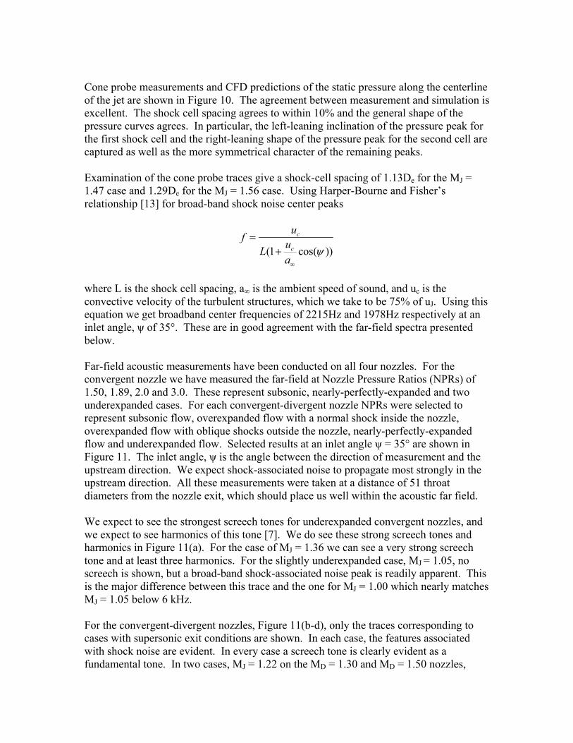
Characteristic boundary conditions are applied to both far field and outflow boundaries, and the total pressure is kept constant at the inlet of the nozzle. Fine grids are clustered around the nozzle and the wake region. This fine mesh domain covers roughly 3 nozzle diameters in the radial direction, 5 diameters upstream of the nozzle exit and 25 diameters downstream. Very coarse grids, however, are used in the far field regions to avoid wave reflections from the numerical boundaries. The grid used is shown in Figure 6. Both overexpanded and underexpanded jet flows from the CD nozzle with the design Mach number of 1.5 are simulated. More details of the numerical approach and validation will be presented at the 47th AIAA Aerospace Sciences Meeting, 2009. Results Flow-field determination by CFD is shown in Figure 7. Static pressure and Mach number distributions are shown from upstream of the throat to two exit diameters past the nozzle exit plane for three conditions corresponding to the pressure ratios for overexpanded, perfectly-expanded and underexpanded cases. All three cases are strikingly similar. For a contoured nozzle one would expect the shock train to initiate at the nozzle lip for the over- and underexpanded cases and no shocks or expansions at all for the case of perfect expansion. What we see instead is a shock structure which is strikingly similar for all three cases. There is a shock shed from the throat which interacts with the shock or expansion fan shed from the lip. This throat shock is present even when the exit pressure matches the ambient pressure and sets off a shock train in the case where a contoured nozzle would yield a shock-free flow. This behavior is confirmed by shadowgraph. Figure 8 shows shadowgraph images for a range of NPRs. The nozzle is opaque so we can not see the shock shedding at the throat, but the first reflection of this internal shock is clearly visible for all operating conditions. The upper corner of the nozzle is clearly visible in each image. The lower corner is less obvious, but it does appear slightly within the field of view. For all cases, the reflection of the internal shock is visible outside the nozzle. It makes a bright band just past the nozzle. For NPR = 2.50, the band is 0.04De past the nozzle exit. For the remaining cases it is 0.06De or 0.07De past the exit. The CFD predicts this reflection to occur much closer to the nozzle lip (~0.03De), but the shadowgraph images leave no doubt that the reflection is there. In addition to the still images presented here, a shadowgraph movie was taken of the nozzle as the set-point was slowly varied through a range from NPR = 2.0 up to NPR = 5.0, including the points around NPR = 3.70 where theory predicts perfect expansion. Careful observation of the movie reveals that there is no condition with an NPR greater than 2.50 in which the jet is shock free. Figure 9 shows the CFD pressure data represented as “simulated shadowgraph.” This representation does not integrate across the thickness of the jet, so it is not a direct comparison to the shadowgraph from the experiments, but it is suggestive and enlightening. Looking closely at the region near the nozzle lip we can see that if we were to extend the line defined by the internal shock until it encountered the outer edge of the jet it would in fact extend beyond the nozzle lip and create an external reflection.
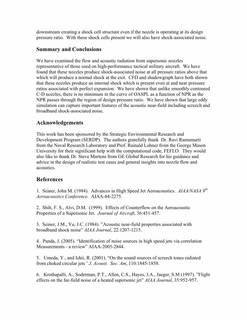
Cone probe measurements and CFD predictions of the static pressure along the centerline of the jet are shown in Figure 10. The agreement between measurement and simulation is excellent. The shock cell spacing agrees to within 10% and the general shape of the pressure curves agrees. In particular, the left-leaning inclination of the pressure peak for the first shock cell and the right-leaning shape of the pressure peak for the second cell are captured as well as the more symmetrical character of the remaining peaks. Examination of the cone probe traces give a shock-cell spacing of 1.13De for the MJ = 1.47 case and 1.29De for the MJ = 1.56 case. Using Harper-Bourne and Fisher’s relationship [13] for broad-band shock noise center peaks
(1 cos( ))
c
c
uf uLa
ψ∞
=+
where L is the shock cell spacing, a∞ is the ambient speed of sound, and uc is the convective velocity of the turbulent structures, which we take to be 75% of uJ. Using this equation we get broadband center frequencies of 2215Hz and 1978Hz respectively at an inlet angle, ψ of 35°. These are in good agreement with the far-field spectra presented below. Far-field acoustic measurements have been conducted on all four nozzles. For the convergent nozzle we have measured the far-field at Nozzle Pressure Ratios (NPRs) of 1.50, 1.89, 2.0 and 3.0. These represent subsonic, nearly-perfectly-expanded and two underexpanded cases. For each convergent-divergent nozzle NPRs were selected to represent subsonic flow, overexpanded flow with a normal shock inside the nozzle, overexpanded flow with oblique shocks outside the nozzle, nearly-perfectly-expanded flow and underexpanded flow. Selected results at an inlet angle ψ = 35° are shown in Figure 11. The inlet angle, ψ is the angle between the direction of measurement and the upstream direction. We expect shock-associated noise to propagate most strongly in the upstream direction. All these measurements were taken at a distance of 51 throat diameters from the nozzle exit, which should place us well within the acoustic far field. We expect to see the strongest screech tones for underexpanded convergent nozzles, and we expect to see harmonics of this tone [7]. We do see these strong screech tones and harmonics in Figure 11(a). For the case of MJ = 1.36 we can see a very strong screech tone and at least three harmonics. For the slightly underexpanded case, MJ = 1.05, no screech is shown, but a broad-band shock-associated noise peak is readily apparent. This is the major difference between this trace and the one for MJ = 1.00 which nearly matches MJ = 1.05 below 6 kHz. For the convergent-divergent nozzles, Figure 11(b-d), only the traces corresponding to cases with supersonic exit conditions are shown. In each case, the features associated with shock noise are evident. In every case a screech tone is clearly evident as a fundamental tone. In two cases, MJ = 1.22 on the MD = 1.30 and MD = 1.50 nozzles,

higher harmonics of screech are apparent as well. In all cases we can see a broadband shock-associated hump to the right of the fundamental screech tone. Figure 12 shows a range of inlet angles for the MD = 1.50 nozzle. Subfigure (a) shows an overexpanded condition with an NPR of 3.50 corresponding to MJ of 1.47. Subfigure (c) shows an underexpanded condition with an NPR of 4.0 corresponding to MJ of 1.56. In both of these conditions we can see a screech tone on the forward angles, becoming weaker as the directivity angle increases. This diminution of the intensity of the screech tone is faster in the underexpanded case. In both under- and overexpanded cases we see the frequency of the broadband shock-associated peak increases and the amplitude decreases as the directivity angle increases as we would expect. By ψ = 150° the broadband peak and the screech tone have disappeared completely and all we see is the mixing noise. Figure 12(b) shows a nozzle pressure ratio of 3.70 corresponding to MJ = 1.50. For a contoured nozzle this would correspond to perfect expansion and we would expect to see shock-free flow and acoustic spectra with the shock noise features absent. From Figure 12(b) we can see that this is clearly not the case. This case shows the same acoustic features as the over- and underexpanded cases for this nozzle. It is clear that the sharp throated, conic expansion nozzles we are examining in this paper do not achieve a shock free condition, and thus do not achieve perfect expansion. Seiner and Yu [3] have shown that for contoured nozzles there should be a minimum in the OASPL curve as the nozzle pressure ratio passes through the design condition (as MJ passes through MD or as Pe/Patm passes through unity). The mixing noise component from the jet should be a monotonically increasing function of MJ. Added to this mixing noise should be the shock-associated noise, which will disappear as the jet becomes shock free when MJ = MD. Seiner and Yu’s data have been re-plotted in Figure 13 as a function of Pe/Patm along with the curves for all four of the nozzles used in this study. For the MD = 1.30 nozzle, far-field data was taken with fine steps in Pe/Patm in order to be sure that a minimum will not go unobserved. It is clear that there is, in fact, no minimum in the curve at the design set-point. This is another indicator that there is no shock-free flow produced by this kind of nozzle at its design point. Near-field acoustic measurements were taken just outside the jet shear layer for the MD = 1.50 nozzle for NPR values corresponding both to overexpanded, MJ = 1.47, and underexpanded, MJ = 1.56 cases. Spectra from the point nearest the nozzle lip is shown in Figure 14(a). Like the far-field, this spectrum shows the screech peak at 1650Hz. SPL contours for this frequency are plotted in Figure 14(b). These show several repeated bands of high intensity from z/De = 4 to 7. Similar plots for the underexpanded case are shown in Figure 15. In this case the screech peak is at 1500 Hz and the same repeated bands appear from z/De = 3 to 7. Looking at the broad-band shock-associated noise, we see contours plotted in Figure 16. These 1/3-octave band plots are centered on 3150 Hz for subfigure (a), the overexpanded case and centered on 2500 Hz for the underexpanded case, subfigure (b). These bands

roughly correspond to the broadband shock-associated noise peak observed in the far-field at ψ = 90°. The overexpanded jet has a lobe of high SPL evident at z/De = 8.7 and the underexpanded jet has a slightly stronger lobe at z/De = 9.1. CFD for the region inside the flow-field will be presented at the 47th AIAA Aerospace Sciences Meeting. We have good agreement between CFD and experiment in the overlap region matching not only the shapes of the contours, but also the magnitudes of the fluctuations. We expect the two approaches to complement each other in helping us to understand the noise production in detail. Spectra of near-field pressure fluctuation are shown in Figure 17 for regions where the microphone measurement and the computed domain overlap. Subfigures (a-c) are determined from CFD. Subfigures (d-f) are measured at nearby locations. Similar trends are observed in both spectra. Screech, broadband shock-associated noise and turbulent mixing noise are observed in both the simulations and the experiment. Screech is evident in both spectra as is the lower peak at 900 Hz which does not radiate to the far-field. Discussion The stated aim of this project is to understand the radiation of sound produced by jets emanating from nozzles typical of those found on high-performance military aircraft both at design and off-design conditions. What we have found is that the character of the sound produced is generally similar for NPR values corresponding to overexpansion, perfect expansion and underexpansion. This would indicate that even when these nozzles are operated at the pressures they are designed for, they still produce shocks internally and thus also produce shock-associated noise. This situation differs significantly from the behavior of the contoured convergent-divergent nozzles most commonly studied and presented in the literature. In particular we find from CFD and from shadowgraph that we do not produce any shock-free jets from these nozzles at any pressure above that where a normal shock can form at the nozzle exit. Closely spaced far-field measurements of the far-field spectra show no minimum in the forward-directed acoustic radiation as Seiner and Yu have found for contoured nozzles. The acoustic features characteristic of shock-associated noise are present even at and near the nozzles design NPR. These differences arise from the geometry of the nozzles. They have a sharp throat and an expansion section which is conic. It is instructive to consider a bell nozzle of similar area ratio. Such nozzles have historically been employed on rocket exhausts when the nozzle length was to be kept to a minimum. These bell nozzles also have a relatively sharp throat, though not as sharp as ours. The initial flow path just downstream of the throat in these nozzles is angled outward more than our conic nozzles are. The flow then gradually turns back toward the axial direction. If we take the flowpath from a bell nozzle as the shortest shock-free path and consider substitution of our conic expansion geometry, we will see that we are turning the flow into itself relative to the bell-nozzle flowpath. This turning into itself generates shocks at the throat and these shocks reflect
downstream creating a shock cell structure even if the nozzle is operating at its design pressure ratio. With these shock cells present we will also have shock-associated noise. Summary and Conclusions We have examined the flow and acoustic radiation from supersonic nozzles representative of those used on high-performance tactical military aircraft. We have found that these nozzles produce shock-associated noise at all pressure ratios above that which will produce a normal shock at the exit. CFD and shadowgraph have both shown that these nozzles produce an internal shock which is present even at and near pressure ratios associated with perfect expansion. We have shown that unlike smoothly contoured C-D nozzles, there is no minimum in the curve of OASPL as a function of NPR as the NPR passes through the region of design pressure ratio. We have shown that large eddy simulation can capture important features of the acoustic near-field including screech and broadband shock-associated noise. Acknowledgements This work has been sponsored by the Strategic Environmental Research and Development Program (SERDP). The authors gratefully thank Dr. Ravi Ramamurti from the Naval Research Laboratory and Prof. Rainald Lohner from the George Mason University for their significant help with the computational code, FEFLO. They would also like to thank Dr. Steve Martens from GE Global Research for his guidance and advice in the design of realistic test cases and general insights into nozzle flow and acoustics. References 1. Seiner, John M. (1984). Advances in High Speed Jet Aeroacoustics. AIAA/NASA 9th Aeroacoustics Conference. AIAA-84-2275. 2. Shih, F. S., Alvi, D.M. (1999). Effects of Counterflow on the Aeroacoustic Properties of a Supersonic Jet. Journal of Aircraft, 36:451-457. 3. Seiner, J.M., Yu, J.C. (1984). ”Acoustic near-field properties associated with broadband shock noise” AIAA Journal, 22:1207-1215. 4. Panda, J. (2005). “Identification of noise sources in high speed jets via correlation Measurements - a review” AIAA-2005-2844. 5. Umeda, Y., and Ishii, R. (2001). “On the sound sources of screech tones radiated from choked circular jets” J. Acoust. Soc. Am, 110:1845-1858. 6. Krothapalli, A., Soderman, P.T., Allen, C.S., Hayes, J.A., Jaeger, S.M (1997). ”Flight effects on the far-field noise of a heated supersonic jet” AIAA Journal, 35:952-957.

7. Tam, C.K.W. (1991). “Jet noise generated by large-scale coherent motion” Aeroacoustics of Flight Vehicles: Theory and Practice, NASA RP 1258, Vol. 1. 8. Callender, B., Gutmark, E. and Dimicco, R. (2002). “The design and validation of a coaxial nozzle acoustic test facility,” AIAA-2002-369. 9. Cooper, M., and Webster, R. (1951). “The use of an uncalibrated cone for determination of flow angles and Mach numbers at supersonic speeds,” NACA-TN-2190. 10. Lohner, R. (1988), FEM-FCT: Combining unstructured grids with high resolution, Communications in Applied Numerical Methods, Vol 4, 717-729 11. Boris, J.P. and Book, D.L.(1973), Flux-corrected Transport I:SHASTA a fluid transport algorithm that works, Journal of Computational Physics, 11 38. 12. Grinstein, F.F. and Fureby, C. (2005), On Monotonically Integrated Large Eddy Simulation of Turbulent Flows Based on FCT Algorithms, Chapter 3 in Flux-Corrected Transport: Principles, Algorithms, and Applications , Eds., D. Kuzmin, R. Lohner, and S. Turek, Springer, pp. 79-104. 13. Harper-Bourne, M., Fisher, M., J., “The Noise from Shockwaves in Supersonic Jets,” Proceedings (No. 131) of the AGARD Conference on Noise Mechanisms, Brussels, Belgium, 1973

Figure 1 -- A typical far-field acoustic spectrum for an imperfectly expanded supersonic jet (forward quadrant; ψ = 35°, MD = 1.50, MJ = 1.47).
Mixing noise
Screech
Broadband shock associated noise
Figure 2 – A sketch containing the acoustic sources locations in an imperfectly expanded supersonic jet.

Figure 3 – Convergent-divergent nozzle installed. (a) complete test article. (b) close-up of nozzle.
(a) (b)
Figure 4 – Nozzles simulating the exhausts of tactical jets. (a) Cross sections of all four nozzles, (b) Exit details of the MD=1.65 nozzle.
(a) (b)
MD = 1.00
MD = 1.30
MD = 1.50
MD = 1.65

Figure 6 – Unstructured tetrahedral grid. (a) Complete domain. (b) Nozzle exit detail.
(a) (b)
Figure 5 – Plan view of UC-GDPL’s Aeroacoustic Test Facility. (a) far-field acoustic arrangement. (b) near-field acoustic arrangement.
(a) (b)

(a)
Figure 7 – CFD flow-field inside the nozzle and near the exit for MD = 1.50. (a) Static pressure, overexpanded pressure ratio, NPR = 3.50, MJ = 1.47. (b) Static pressure, perfectly expanded pressure ratio, NPR = 3.70, MJ = 1.56. (c) Static pressure, underexpanded pressure ratio, NPR = 4.00, MJ = 1.56. (d) Mach number, overexpanded pressure ratio, NPR = 3.50, MJ = 1.47. (e) Mach number, perfectly expanded pressure ratio, NPR = 3.70, MJ = 1.56. (f) Mach number, underexpanded pressure ratio, NPR = 4.00, MJ = 1.56.
(d)
(b) (c)
(e) (f)

Figure 8 – Convergent-divergent nozzle (MD=1.5) shadowgraph. One hundred images averaged to suppress turbulence and emphasize shock structures.
NPR = 2.50, MJ = 1.22
NPR = 3.00, MJ = 1.36
NPR = 3.50, MJ = 1.47
NPR = 4.00, MJ = 1.56
NPR = 4.50, MJ = 1.64
NPR = 5.00, MJ = 1.71
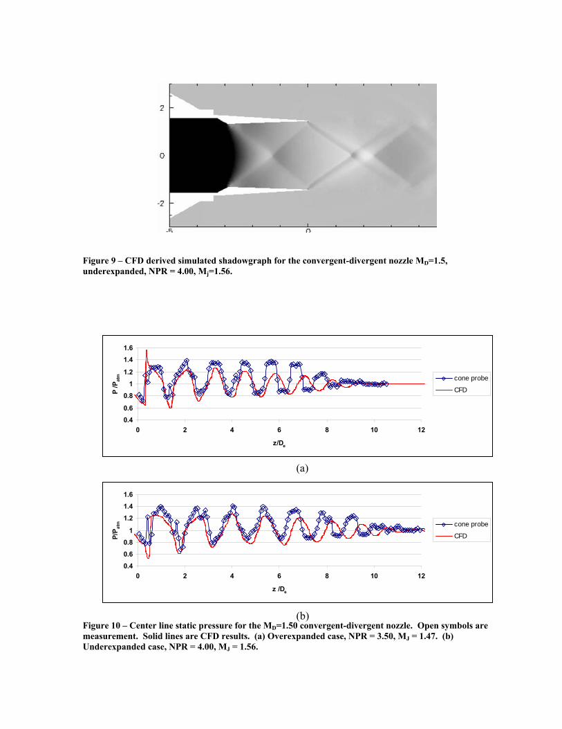
Figure 10 – Center line static pressure for the MD=1.50 convergent-divergent nozzle. Open symbols are measurement. Solid lines are CFD results. (a) Overexpanded case, NPR = 3.50, MJ = 1.47. (b) Underexpanded case, NPR = 4.00, MJ = 1.56.
(a)
(b)
0.40.6
0.81
1.2
1.41.6
0 2 4 6 8 10 12
z/De
P /P
atm cone probe
CFD
0.40.60.8
1
1.21.41.6
0 2 4 6 8 10 12
z /De
P/P at
m cone probe
CFD
Figure 9 – CFD derived simulated shadowgraph for the convergent-divergent nozzle MD=1.5, underexpanded, NPR = 4.00, Mj=1.56.

(a) (b)
Figure 11 – Far-field acoustic measurements at an inlet angle, ψ, of 35° and a distance of 51 throat diameters from the nozzle exit. (a) Convergent nozzle, MD = 1.00. (b) Convergent-divergent nozzle, MD = 1.30. (c) Convergent-divergent nozzle, MD = 1.50. (d) Convergent-divergent nozzle, MD = 1.65.
(c) (d)

Figure 12 – Far-field acoustic measurements for the convergent-divergent nozzle with Ae/A* = 1.181 (MD=1.50) . Each trace is for a different angle, ψ, measured from the upstream direction. All measurements were taken from a distance of 51 throat diameters. (a) Overexpanded pressure ratio, MJ = 1.47. (b) Perfect expansion pressure ratio, MJ = 1.50. (c) Underexpanded pressure ratio MJ = 1.56.
(a)
(b) (c)
Figure 13 – Variation in OASPL with Pe/Patm.
90
100
110
120
130
140
0.6 0.8 1 1.2 1.4 1.6
Pe/Patm
OA
SPL
at ψ
= 3
5° [d
B]
Md = MjSeiner & YuMd = 1.00Md = 1.30Md = 1.50Md = 1.65

Figure 15 – Near-field measurements for MD = 1.50, MJ = 1.56. (a) Spectrum at z/De = 0, r/De = 0.849 showing the screech peak at 1500 Hz. (b) Near-field narrow-band SPL contours in dB for 1500 Hz.
(a) (b)
Figure 14 – Near-field measurements for MD = 1.50, MJ = 1.47. (a) Spectrum at z/De = 0, r/De = 0.849 showing the screech peak at 1650 Hz. (b) Near-field narrow-band SPL contours in dB for 1650 Hz.
(a) (b)

Figure 16 – Near-field measurements for MD = 1.50. (a) Near-field contours for the 1/3rd-octave band centered at 3150 Hz for MJ = 1.47. (b) Near-field contours for the 1/3rd-octave band centered at 2500 Hz for MJ = 1.56.
(a) (b)
Figure 17 – Near-field SPL spectra in dB from CFD and measurement at approximately equal positions within the sound field. (a-c) CFD. (e-f) Microphone measurement.
(b) (a) (c)
(e) (d) (f)